catalogo generale condotti sbarre gb legrand ex215028 · illumination (up to 75%, according to uni...
TRANSCRIPT
26
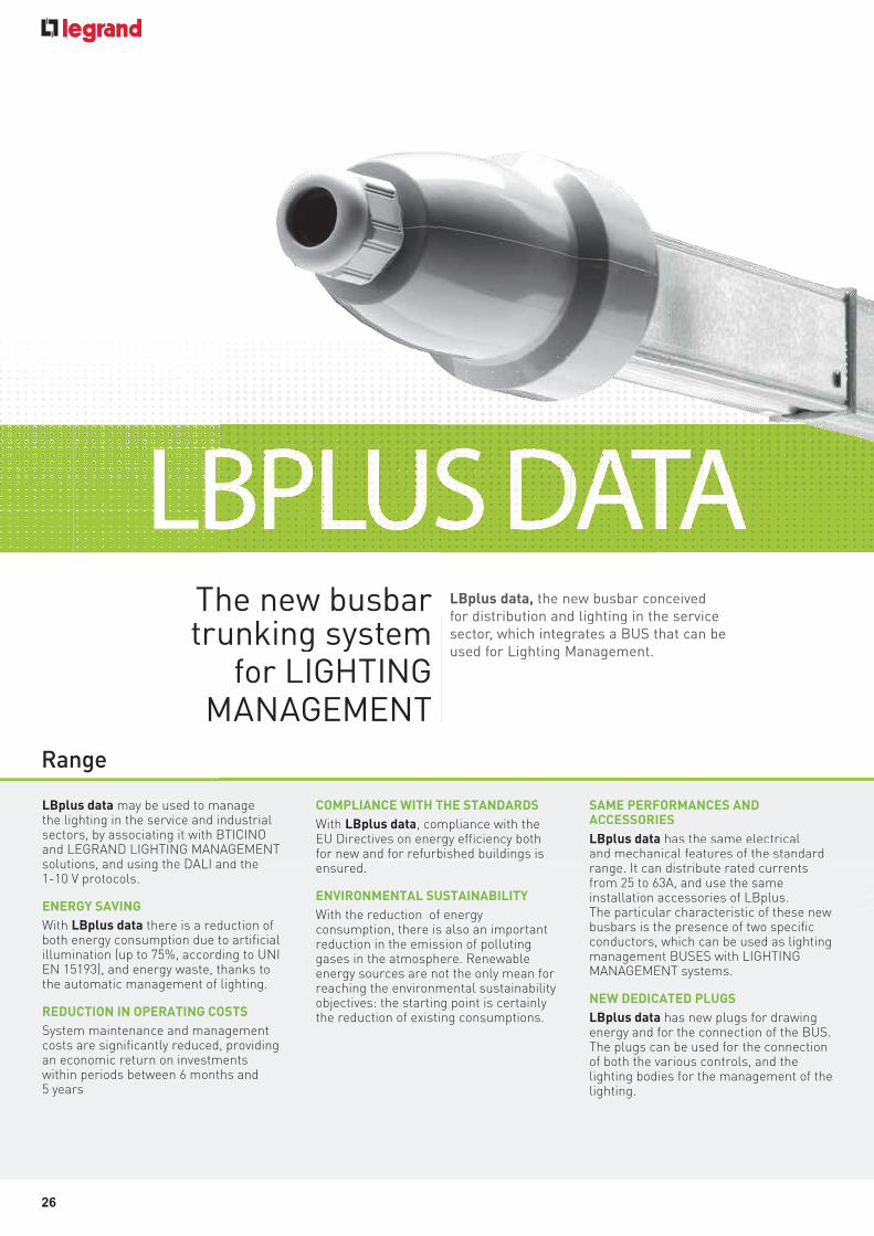
LBPLUS DATA
LBplus data may be used to manage the lighting in the service and industrial sectors, by associating it with BTICINO and LEGRAND LIGHTING MANAGEMENT solutions, and using the DALI and the 1-10 V protocols.
ENERGY SAVING
With LBplus data there is a reduction of both energy consumption due to artificial illumination (up to 75%, according to UNI EN 15193), and energy waste, thanks to the automatic management of lighting.
REDUCTION IN OPERATING COSTS
System maintenance and management costs are significantly reduced, providing an economic return on investments within periods between 6 months and 5 years
COMPLIANCE WITH THE STANDARDS
With LBplus data, compliance with the EU Directives on energy efficiency both for new and for refurbished buildings is ensured.
ENVIRONMENTAL SUSTAINABILITY
With the reduction of energy consumption, there is also an important reduction in the emission of polluting gases in the atmosphere. Renewable energy sources are not the only mean for reaching the environmental sustainability objectives: the starting point is certainly the reduction of existing consumptions.
SAME PERFORMANCES AND ACCESSORIES
LBplus data has the same electrical and mechanical features of the standard range. It can distribute rated currents from 25 to 63A, and use the same installation accessories of LBplus. The particular characteristic of these new busbars is the presence of two specific conductors, which can be used as lighting management BUSES with LIGHTING MANAGEMENT systems.
NEW DEDICATED PLUGS
LBplus data has new plugs for drawing energy and for the connection of the BUS. The plugs can be used for the connection of both the various controls, and the lighting bodies for the management of the lighting.
The new busbar trunking system
for LIGHTING MANAGEMENT
LBplus data, the new busbar conceived for distribution and lighting in the service
sector, which integrates a BUS that can be
used for Lighting Management.
Range
manage industrial BTICINO AGEMENT
d th
COMPLIANCE WITH THE STANDARDS
With LBplus data, compliance with the EU Directives on energy efficiency both for new and for refurbished buildings is
SAME PERFORMANCES AND ACCESSORIES
LBplus data has the same electrical and mechanical features of the standard
he new busbar unking system for LIGHTING
MANAGEMENT
LBplus data, the new busbar conceived for distribution and lighting in the service
sector, which integrates a BUS that can be
used for Lighting Management.
27
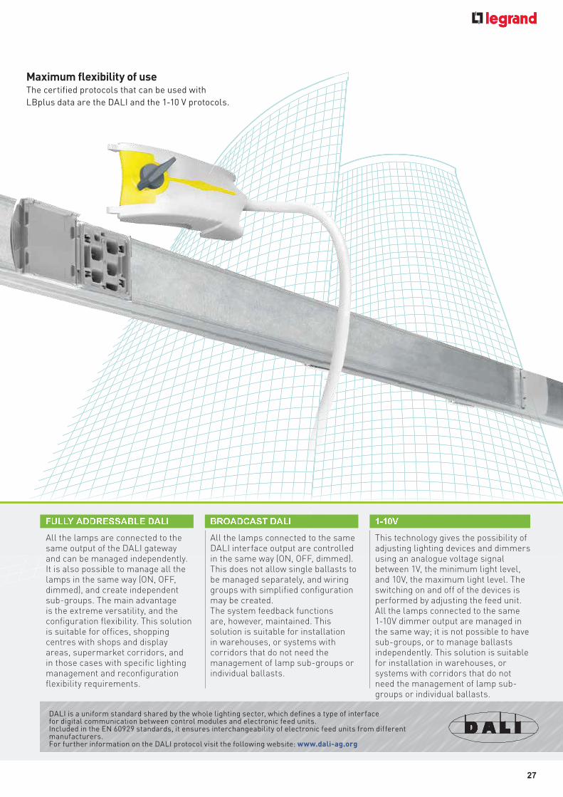
DALI is a uniform standard shared by the whole lighting sector, which defines a type of interface for digital communication between control modules and electronic feed units. Included in the EN 60929 standards, it ensures interchangeability of electronic feed units from different manufacturers. For further information on the DALI protocol visit the following website: www.dali-ag.org
All the lamps are connected to the same output of the DALI gateway and can be managed independently. It is also possible to manage all the lamps in the same way (ON, OFF, dimmed), and create independent sub-groups. The main advantage is the extreme versatility, and the configuration flexibility. This solution is suitable for offices, shopping centres with shops and display areas, supermarket corridors, and in those cases with specific lighting management and reconfiguration flexibility requirements.
� � � � � � � � � � � � � � � � � � All the lamps connected to the same DALI interface output are controlled in the same way (ON, OFF, dimmed). This does not allow single ballasts to be managed separately, and wiring groups with simplified configuration may be created. The system feedback functions are, however, maintained. This solution is suitable for installation in warehouses, or systems with corridors that do not need the management of lamp sub-groups or individual ballasts.
� � � � � � � � � � This technology gives the possibility of adjusting lighting devices and dimmers using an analogue voltage signal between 1V, the minimum light level, and 10V, the maximum light level. The switching on and off of the devices is performed by adjusting the feed unit. All the lamps connected to the same 1-10V dimmer output are managed in the same way; it is not possible to have sub-groups, or to manage ballasts independently. This solution is suitable for installation in warehouses, or systems with corridors that do not need the management of lamp sub-groups or individual ballasts.
� � � � �
Maximum flexibility of use The certified protocols that can be used with
LBplus data are the DALI and the 1-10 V protocols.
28
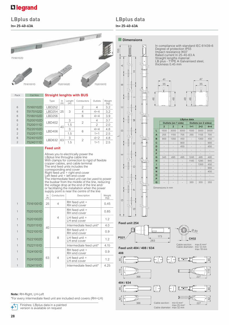
LBplus dataIn= 25-40-63A
LBplus dataIn= 25-40-63A
75160102D
75161001D
Pack Cat.Nos Straight lenghts with BUS
Type In(A)
Lenght(m)
Conductors Outlets Weight(kg)
6 75160102D LBD252
25 3
2 4 3.2
6 75170102D LBD254 4 4+4 3.2
6 75180102D LBD256 6 4+4 3.9
6 75200102DLBD402
40
32
4 3.7
2 75200111D 1.5 2 2.0
6 75220102DLBD406
36
4+4 4.8
2 75220111D 1.5 1+1 2.5
6 75240102DLBD632 63
32
4+2 4.8
2 75240111D 1.5 1+1 2.5
Feed unit
Allows you to electrically power the LBplus line througha cable lineWith clamps for connection to rigid of flexible copper cables, and cable terminalThe end feed units includes the corresponding end coverRight feed unit + right end coverLeft feed unit + left end coverThe intermediate feed unit can be used to power the busbar from the middle of the line, reducing the voltage drop at the end of the line and/or facilitating the installation when the power supply point is near the centre of the line
In(A)
Conductors Description Weight(kg)
1 75161001D 25 4RH feed unit + RH end cover
0.45
1 75201001D
40
4
RH feed unit + RH end cover
0.85
1 75201002DLH feed unit + LH end cover
1.2
1 75201151D Intermediate feed unit* 4.0
1 75221001D
8
RH feed unit + RH end cover
0.9
1 75221002DLH feed unit + LH end cover
1.2
1 75221151D Intermediate feed unit* 4.15
1 75241001D
63 4
RH feed unit + RH end cover
0.9
1 75241002DLH feed unit + LH end cover
1.2
1 75241151D Intermediate feed unit* 4.25
A
15
0
BC
DE
FG
IH
QP
ON
M
L
41
35
48
46
46
48
LBplus data
Outlets (on 1 side) Outlets (on 2 sides)
2 2 4 1+1 2+2 4+4
L 1500 3000 3000 1500 3000 3000
A 255 1155 705 255 1155 705
B 900 1350 450 - 1350 450
C - - 900 - - 900
D - - 450 - - 450
E - - - - - -
F - - - - - -
G 345 495 495 1245 495 495
H - - - 1145 1295 845
I - - - - 1350 450
M - - - - - 900
N - - - - - 450
O - - - - - -
P - - - - - -
Q - - - 355 355 355
Dimensions in mm
Cable section: max 6 mm2
Cable diameter: min 12 mm max 18 mm
Feed unit 254
Feed unit 404 / 408 / 634
Finishes: LBplus data in a painted version is available on request
Dimensions
PG21 173
Ø 80
283CH32
In compliance with standard IEC 61439-6Degree of protection IP55Impact resistance IK07Rated current In 25-40-63 AStraight lengths material:LB plus - TYPE A Galvanised steel, thickness 0.45 mm
Note: RH-Right, LH-Left
*For every intermediate feed unit are included end covers (RH+LH)
35
47
408
404 / 634
366
115
85
366
82
85
82
115
85
227
82
227
85
Cable section: min 6 mm2
max 25 mm2
Cable diameter: max 32 mm
75201002D 75201001D75201002D 75201001D
29
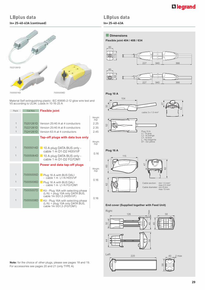
LBplus dataIn= 25-40-63A
LBplus dataIn= 25-40-63A (continued)
Note: for the choice of other plugs, please see pages 18 and 19.
For accessories see pages 20 and 21 (only TYPE A)
75005014D 75005008D
75221261D
Flexible joint 404 / 408 / 634
End cover (Supplied together with Feed Unit)
220 40 2 max
58
126 58
2 m
ax
40
32
44
58
40
Right
Left
Plug 10 A
Plug 16 A
Cable section: min 1.5 mm2
max 2.5 mm2
Cable diameter: min 8 mm max 13 mm
cable 3 x 1.5 mm2
Plug 10 AL1 - N grayL2 - N orangeL3 - N blueL - N2 magentaD1 - D2 yellow
Pack Cat.Nos Flexible joint
Weight(kg)
1 75201261D Version 25/40 A at 4 conductors 2.25
1 75221261D Version 25/40 A at 8 conductors 2.35
1 75241261D Version 63 A at 4 conductors 2.45
Tap-off plugs with data bus only
Weight(kg)
1 75005014D 10 A plug DATA BUS only - cable 1 m D1-D2 H05VVF
0.161 75005064D 10 A plug DATA BUS only -
cable 1 m D1-D2 FG7OM1
Power and data tap-off plugs Weight
(kg)
1 75005005D Plug 16 A with BUS DALI - cable 1 m L1-N H05VVF
0.161 75005006D Plug 16 A with BUS DALI
- cable 1 m L1-N FG7OM1
1 75005007D Kit - Plug 16A with selecting phase (L-N) + plug 10A only DATA BUS, cable 1m 5G1,5 (H05VVF)
0.161 75005008D Kit - Plug 16A with selecting phase
(L-N) + plug 10A only DATA BUS, cable 1m 5G1,5 (FG7OM1)
Material Self extinguishing plastic: IEC 60695-2-12 glow wire test and V0 according to UL94. Loads In 10-16-25 A
Dimensions
104
115
32
60 4
7
82
62
27
62
52
85
115
227 940 366
85
82
227 940 366
30
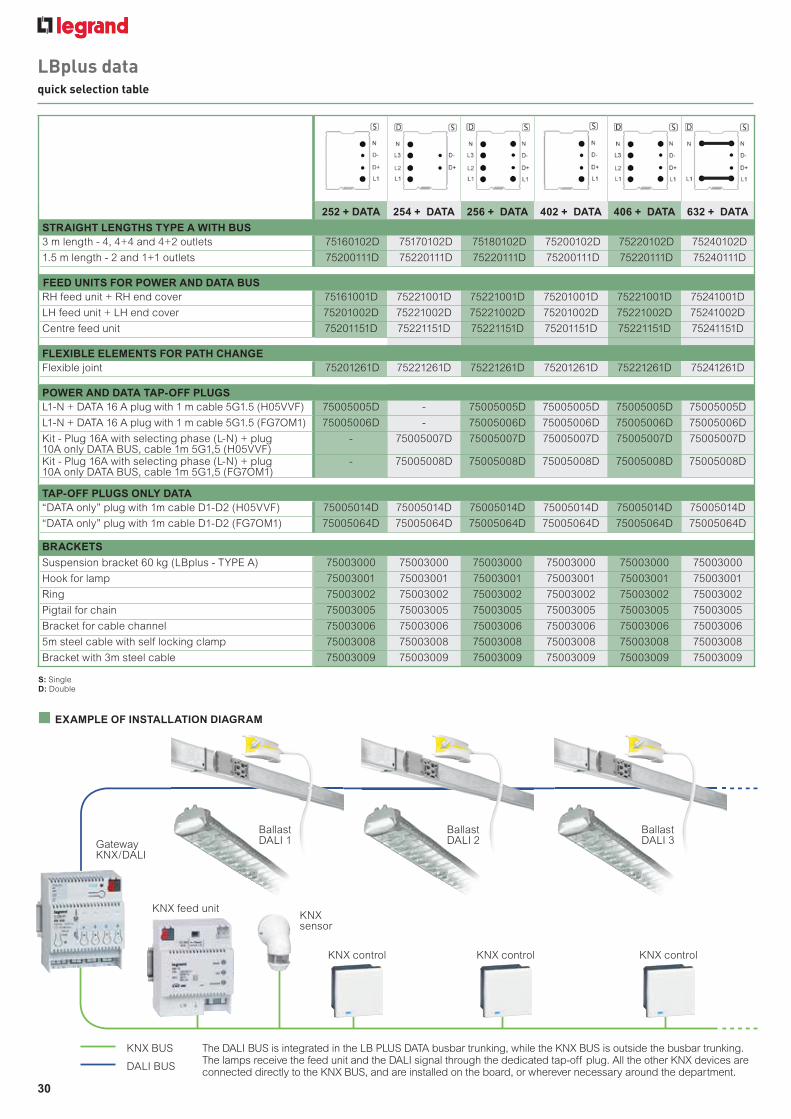
LBplus dataquick selection table
252 + DATA 254 + DATA 256 + DATA 402 + DATA 406 + DATA 632 + DATA
STRAIGHT LENGTHS TYPE A WITH BUS
3 m length - 4, 4+4 and 4+2 outlets 75160102D 75170102D 75180102D 75200102D 75220102D 75240102D
1.5 m length - 2 and 1+1 outlets 75200111D 75220111D 75220111D 75200111D 75220111D 75240111D
FEED UNITS FOR POWER AND DATA BUS
RH feed unit + RH end cover 75161001D 75221001D 75221001D 75201001D 75221001D 75241001D
LH feed unit + LH end cover 75201002D 75221002D 75221002D 75201002D 75221002D 75241002D
Centre feed unit 75201151D 75221151D 75221151D 75201151D 75221151D 75241151D
FLEXIBLE ELEMENTS FOR PATH CHANGE
Flexible joint 75201261D 75221261D 75221261D 75201261D 75221261D 75241261D
POWER AND DATA TAP-OFF PLUGS
L1-N + DATA 16 A plug with 1 m cable 5G1.5 (H05VVF) 75005005D - 75005005D 75005005D 75005005D 75005005D
L1-N + DATA 16 A plug with 1 m cable 5G1.5 (FG7OM1) 75005006D - 75005006D 75005006D 75005006D 75005006D
Kit - Plug 16A with selecting phase (L-N) + plug 10A only DATA BUS, cable 1m 5G1,5 (H05VVF)
- 75005007D 75005007D 75005007D 75005007D 75005007D
Kit - Plug 16A with selecting phase (L-N) + plug 10A only DATA BUS, cable 1m 5G1,5 (FG7OM1)
- 75005008D 75005008D 75005008D 75005008D 75005008D
TAP-OFF PLUGS ONLY DATA
“DATA only” plug with 1m cable D1-D2 (H05VVF) 75005014D 75005014D 75005014D 75005014D 75005014D 75005014D
“DATA only” plug with 1m cable D1-D2 (FG7OM1) 75005064D 75005064D 75005064D 75005064D 75005064D 75005064D
BRACKETS
Suspension bracket 60 kg (LBplus - TYPE A) 75003000 75003000 75003000 75003000 75003000 75003000
Hook for lamp 75003001 75003001 75003001 75003001 75003001 75003001
Ring 75003002 75003002 75003002 75003002 75003002 75003002
Pigtail for chain 75003005 75003005 75003005 75003005 75003005 75003005
Bracket for cable channel 75003006 75003006 75003006 75003006 75003006 75003006
5m steel cable with self locking clamp 75003008 75003008 75003008 75003008 75003008 75003008
Bracket with 3m steel cable 75003009 75003009 75003009 75003009 75003009 75003009
S: SingleD: Double
EXAMPLE OF INSTALLATION DIAGRAM
KNX feed unit
KNX BUS
DALI BUS
KNX control
KNX sensor
KNX control KNX control
The DALI BUS is integrated in the LB PLUS DATA busbar trunking, while the KNX BUS is outside the busbar trunking. The lamps receive the feed unit and the DALI signal through the dedicated tap-off plug. All the other KNX devices are connected directly to the KNX BUS, and are installed on the board, or wherever necessary around the department.
Gateway KNX/DALI
ALLATION DIAGRAM
Ballast DALI 1
Ballast DALI 2
Ballast DALI 3

31
LBplus datatechnical data
Room temperature [ °C ] 15 20 25 30 35 40 45 50 55 60
Kt factor 1.15 1.12 1.08 1.05 1.025 1 0.975 0.95 0.93 0.89
Distance betweensuspension brackets
Concentrated load Distributed load
1.5 m 40 kg 50 kg/m (75 kg)**
2 m 30 kg 30 kg/m (60 kg)**
3 m 20 kg 13 kg/m (39 kg)**
Protection from short circuit (In 100 A).Legrand busbar trunking systems with a rated current lower than or equal to 100 A (LBplus - MS 63 e 100) are properly protected through an MCB (Modular Circuit Breaker) with a rated current lower than or equal to that of the busbar. This protection is guaranteed up to the MCB breaking capacity
Product fully in compliance with the standard: IEC 61439-6, CEI EN 61439-6
Temperature rating schedule according to the room temperature
Multiplier coefficient of rated current for room temperature values different from 40° C
Mechanical loads permitted tableThe table shows the maximum weights (kg) that can be supported, both for concentrated, and distributed loads
LBplus data
** Distributed load total weight
LBPLUS DATA TYPE A
252 DATA 254 DATA 256 DATA 402 DATA 406 DATA 632 DATA
Number of live conductors 2+2 DATA 4+2 DATA 6+2 DATA 2+2 DATA 6+2 DATA 2+2 DATA
Overall dimension of the busbars LxH [mm] 35 x 46 35 x 46 35 x 46 35 x 46 35 x 46 35 x 46
Rated current In [A] 25 25 25 40 40 63
Operational voltage Ue [V] 400 400 400 400 400 400
Insulational voltage Ui [V] 500 500 500 500 500 500
Frequency f [Hz] 50/60 50/60 50/60 50/60 50/60 50/60
Rated short-time current (0.1 s) Icw [kArms] - 2,2 2,2 - 2,7 2,7
Peak current Ipk [kA] - 3,3 3,3 - 4,1 4,1
Single phase rated short-time current (0,1 s) Icw [kArms] 1,3 1,3 1,3 1,6 1,6 1,6
Singlephase Peak current Ipk [kA] 2,0 2,0 2,0 2,4 2,4 2,4
Thermal limit I²t [A²s x 106] 0,174 0,484 0,484 0,262 0,729 0,729
Phase resistance (20 °C) R20 [m /m] 4,761 4,761 4,761 3,190 3,190 1,595
Phase resistance at thermal conditions Rt [m /m] 5,656 5,656 5,656 3,802 3,802 1,901
Phase reactance (50 Hz) X [m /m] 0,229 0,229 0,229 0,236 0,236 0,118
Phase impedance Z [m /m] 4,767 4,767 4,767 3,199 3,199 1,599
Resistance of protective conductor (sheet) RPE' [m /m] 1,695 1,695 1,695 1,695 1,695 1,695
Reactance of the protective bar (50 Hz) XPE [m /m] 0,222 0,222 0,222 0,222 0,222 0,222
Resistance of the fault loop Ro [m /m] 6,456 6,456 6,456 4,885 4,885 3,290
Reactance of the fault loop Xo [m /m] 0,451 0,451 0,451 0,458 0,458 0,340
Impedance of the fault loop Zo [m /m] 6,472 6,472 6,472 4,906 4,906 3,308
Voltage drop with distribuited load referred to V3f (**)
V 10-3 cos = 0,7 [V/m/A] 4,123* 3,570 3,570 2,830* 2,451 1,225
V 10-3 cos = 0,75 [V/m/A] 4,393* 3,805 3,805 3,008* 2,605 1,302
V 10-3 cos = 0,8 [V/m/A] 4,662* 4,038 4,038 3,183* 2,757 1,378
V 10-3 cos = 0,85 [V/m/A] 4,928* 4,268 4,268 3,356* 2,906 1,453
V 10-3 cos = 0,90 [V/m/A] 5,190* 4,495 4,495 3,525* 3,052 1,526
V 10-3 cos = 0,95 [V/m/A] 5,445* 4,715 4,715 3,686* 3,192 1,596
V 10-3 cos = 1 [V/m/A] 5,656* 4,898 4,898 3,802* 3,293 1,646
Weight p [kg/m] 1,04 1,25 1,28 1,19 1,56 1,56
Fire load [kWh/m] 1,0 1,9 1,9 1,0 1,9 1,9
Degree of protection IP 55 55 55 55 55 55
Degree of impact resistance IK 07 07 07 07 07 07
Losses for the Joule effect at nominal current P [W/m] 10,6 10,6 10,6 18,2 18,2 22,6
Ambient temperature min./MAX. t [°C] -5/50 -5/50 -5/50 -5/50 -5/50 -5/50
(**) THREE-PHASE: V3f= 3/2 x (Rt cos + X sen ) V3f(In)=I x L x V3f: (knowing the current and length of the line) V3f(In)%=( V3f(In) / Ue) x 100 (%)To calculate the V1f (SINGLE-PHASE) on distributed load: V1f= 1/2 x (2Rt cos + 2X sen ) V1f(In)=I x L x V1f: (knowing the current and length of the line) V1f(In)%=( V1f(In) / Ue) x 100 (%) I = operating current (A)L = lenght (m)
(*) Single phase values with distribuited load