catalogue elmark electrical 2015
DESCRIPTION
ÂTRANSCRIPT

CIRCUIT BREAKERS
10 - 41
CIRCUIT BREAKERS
10 - 41
CIRCUIT BREAKERS
14 - 4914 - 24
Miniature circuit breakers (MCB)
25Auxiliary devices for circuit breakers
26 - 30High power safety devices and isolating switches
31Switch disconnectors ISS
32Isolating switches ISS2
33 Manual switching to reserve series EQ 2M
34Dual power change-over switch
CIRCUIT BREAKERS
10 - 4135 - 42
Moulded case circuit breakers
37Moulded case circuit breakers with lock
39Moulded case circuit breakers
40Moulded case circuit breaker with ELCB
42Moulded case circuit breaker DW1 series
43 - 49Auxiliary devices for мoulded case circuit breakers
INDIRECT PROTECTION DEVICES
52 - 6152 - 55
Residual current devices
56 - 58
Combined residual current devices
59 - 61
Surge arresters
CONTACTORS
64 - 7364 - 66
Low voltage contactors LT1-D/K
67
Low voltage contactors LT1-F
68
Low voltage contactors- LP-1D
69
Low voltage contactors CJ19-43
70
Low voltage reverse contactors
71 - 72
Auxiliary contact blocks
73
Module contactors
DEVICES FOR CONTROLAND PROTECTION OF ELECTRICAL MOTORS
76 - 8776 - 77
Thermal relays78 - 79
Thermomagnetic automatic breaker
80
Auxiliary devices for thermomagnetic automatic breaker
81 - 85
Starters86
Frequency inverters
87
Soft starter
CAPACITY COEFFICIENT COMPENSATION
90 - 9190
Complex compensating devices
91
Capacitor batteries for reactive energy compensation
91
Cosφ regulator
TIMERS, RELAYS AND DISPLAYING DEVICES
94 - 11194 - 98
Programmable timers
99 - 100
Digital counters101- 102
Industrial relays103 - 104
Current measurement transformers
105 - 106
Voltage transformers
107 - 111
Displaying measurement devices
ELEMENTS FOR AUTOMATION, MONITORING AND CONTROL
114 - 135114 - 119
Limit switches120
Proximity sensor121
Capacitive sensor122
Photoelectrical sensor
123
Power supplies124 - 127
Rotary switches128 - 132
Buttons and LED indicators
CIRCUIT BREAKERS
10 - 41133
Devices for telpher control
134 - 135
Warning lights and towers
INDUSTRIAL PLUGS AND SOCKETS
138 - 145138
Industrial plugs139
Industrial sockets
DISTRIBUTION BOXES
148 - 157148 - 150
Plastic distribution boxes
151 - 153
Metal distribution boards
151
Metal distribution boxes for flush and surface mounting
154 - 155
Plastic distribution boards
156 - 157
Plastic distribution boards and accessories
CABLE TERMINALS
160 - 165160 - 162
Connection tubes163 - 165
Isolated cable terminals
CABLE INSTALATION SYSTEM
168 - 183168
Plastic cable trunking
169 - 171
Plastic cable trunking accessories
172 - 179
Cable support systems
180 - 181
Distribution boxes182 - 183
Waterproof junction boxes
ACCESSORIES
186 - 197186 - 191
Consummative192
Heat shrinkage tubes
193 - 197
Terminal blocks
TOOLS
200 - 199200 - 205
Manual meters206 - 210
Crimping tools211
Mechanical cutting tools
212 - 213
Isolated VDE tools
ELECTRICAL SWITCHES AND SOCKETS
216 - 236216 - 221
Rhyme series222 - 225
Splendor series226 - 229
Life style series230 - 233
Basic series234 - 235
Waterproof for surface mounting
235 - 236
Plugs

CO
NTEN
TLED INDUSTRIAL LIGHTING
240 - 253240 - 243
High bay fixtures244 - 246
Road fixtures247 - 251
Floodlights252 - 253
Floodlights - Wall Washer
LED INTERIOR LIGHTING
256 - 295256 - 261
LED Panels262 - 267
LED fixtures268 - 269
Emergency lighting fixtures
270 - 273
LED Cabinet lights274 - 281
LED Accent lighting282 - 291
LED Downlight fixtures
292 - 295
LED Spot light fixtures
LED EXTERIOR LIGHTING
298 - 311298 - 301
Facade lighting302 - 303
Garden lighting304 - 305
Wall recessed fixtures
306 - 309
Ground recessed fixtures
310 - 311
Wall mounted fixtures
LED LAMPS AND COMPONENTS
314 - 343314 - 315
LED fixtures T5316 - 317
LED Tubes T8318 - 331
LED Lamps332 - 333
LED modules334 - 337
LED Strip lights338 - 340
Accessories for LED Strip
341 - 343
Power supplies and controls
INDUSTRIAL LIGHTING
346 - 363347 - 351
Road fixtures352 - 355
Floodlights356 - 363
High bay fixtures
INTERIOR LIGHTING
366 - 395366 - 371
Fluorescent lighting372 - 375
Waterproof fluorescent lighting
376 - 377
Fluorescent cabinet lighting
378 - 385
Spot light386 - 387
Cabinet spot lights388
Spot light for bathroom
389
Downlight for bathroom
390 - 395
Downlight fixtures for CFL
EXTERIOR LIGHTING
398 - 405398 - 401
Garden lighting402 - 403
Lanterns404
Facade lighting405
Wall mounted fixtures
LAMPS AND COMPONENTS
408 - 431408 - 417
Compact fluorescent lamps
418 - 419
Fluorescent tubes420 - 422
Discharge lamps423 - 425
Transformers and ballasts
426 - 427
Lamp holders428 - 431
Sensors

4
COM
PAN
Y IN
FORM
ATIO
N
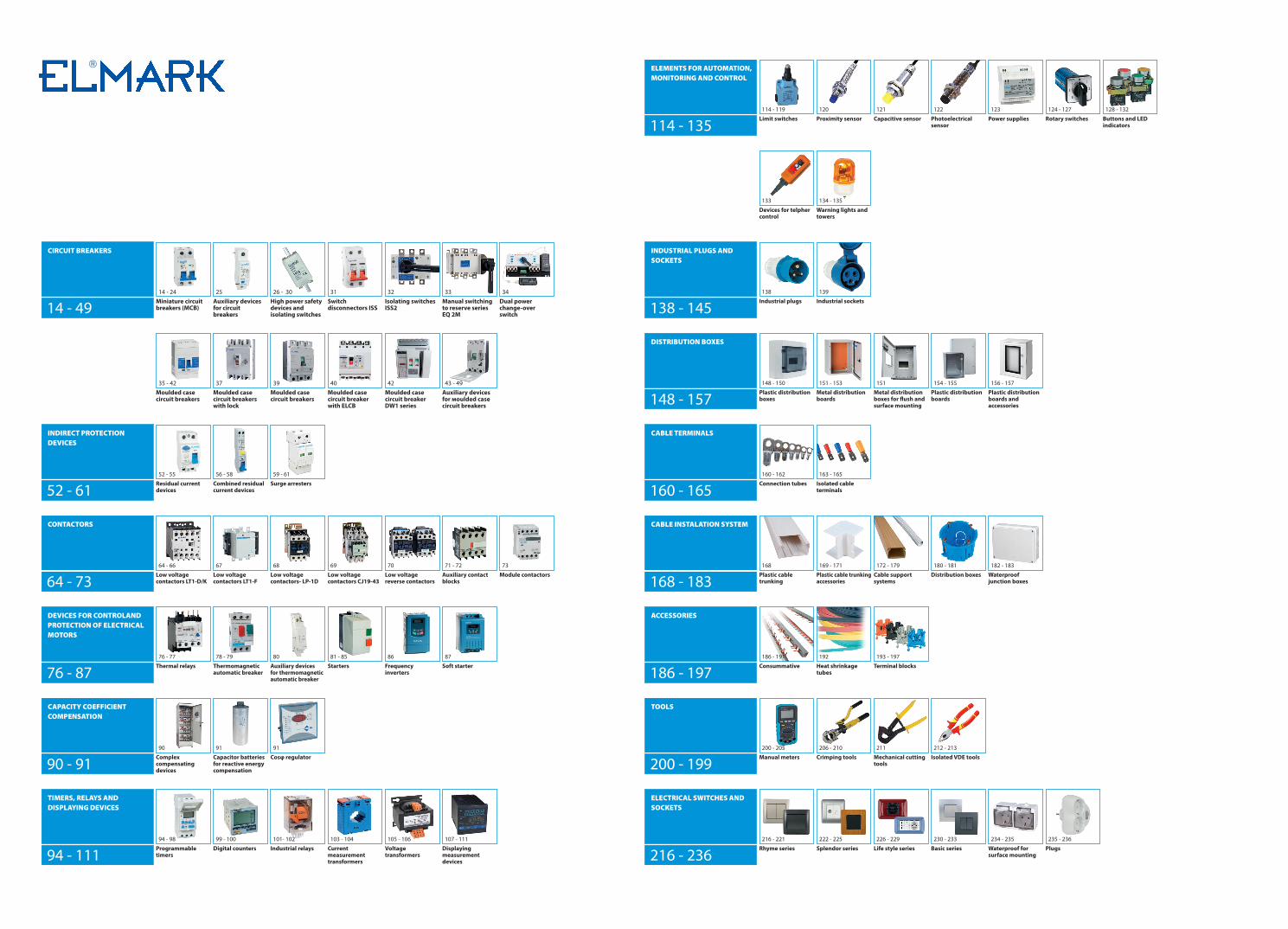
ELMARK is a leading European certified trademark of LOW VOLTAGE ELECTRICAL AND LIGHTING EQUIPMENT, complying with the applicable European standards, incl. the Directive 2006/95/EC (ex.73/23/EEC) Low Voltage Directives (LVD), INTERTEK, RoHS, EMC, ISO 9001:2008 and in reference with the requirements for CE marking.
The holder of the trademark ELMARK is the European company ELMARK HOLDING SE with HEADQUARTER in LONDON, UK.
It represents a group of 14 affiliate companies in 10countries: United Kingdom, Bulgaria, Romania, Hungary, Slovenia, Croatia, Serbia, Bosnia and Herzegovina, Greece, United Arab Emirates.
INTERNATIONAL TRADE OFFICE ELMARK TRADE LTD, Varna, Bulgaria Our professional team of International Trade Managers is dedicated to expand our ELMARK sales network and establish close relations with our clients around the globe and offer quick and competent assistance on any enquiries and questions.
EUROPEAN FACTORY AND WAREHOUSE ELMARK INDUSTRIES SC, Dobrich, Bulgaria The facilities manufacture and maintain significant stock availabilities and provides competitive and quick distribution throughout Europe.
MIDDLE EAST FACTORY AND WAREHOUSE ELMARK INDUSTRIES SC Branch, Dubai, UAE As located in Dubai Silicon Oasis, we are able to provide faster and cost effective solutions
to our clients in Middle East and Africa as well as keep close relationship with our partners to handle and satisfy all demands and requirements.
Our successful commercial policy is due to the high quality of the product range and the successful balance of supply and demand of electrical and lighting equipment. As a result, ELMARK HOLDING SE has been a reliable and reputable partner on the European and world market for already fifteen years, offering good quality products at competitive prices.
SOLUTIONS Over 7000 LOW VOLTAGE ELECTRICAL AND LIGHTING SOLUTIONS
QUALITY Up to 7 YEARS WARRANTY
LIABILITY 1 500 000 EUR ALLIANZ GERMANY
CERTIFICATES
EMC LVD
COMPANYINFORMATION
5
COM
PAN
Y IN
FORM
ATIO
N

6
QUALITY Certificate
QU
ALI
TYCe
rtifi
cate

7
QUALITY Certificate
QU
ALI
TYCe
rtifi
cate

8
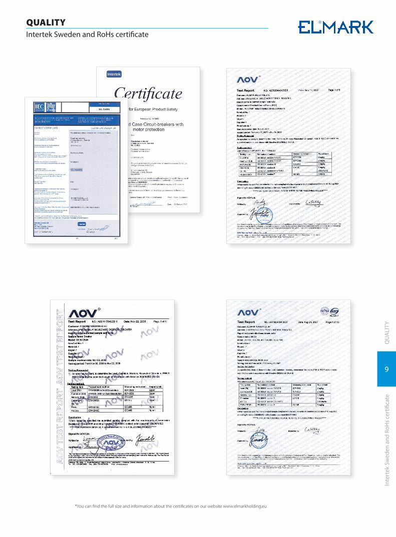
QUALITY Intertek Sweden and RoHs certificate
QU
ALI
TYIn
tert
ek S
wed
en a
nd R
oHs
cert
ifica
te
*You can find the full size and information about the certificates on our website www.elmarkholding.eu
9
QUALITY Intertek Sweden and RoHs certificate
QU
ALI
TYIn
tert
ek S
wed
en a
nd R
oHs
cert
ifica
te
*You can find the full size and information about the certificates on our website www.elmarkholding.eu
10
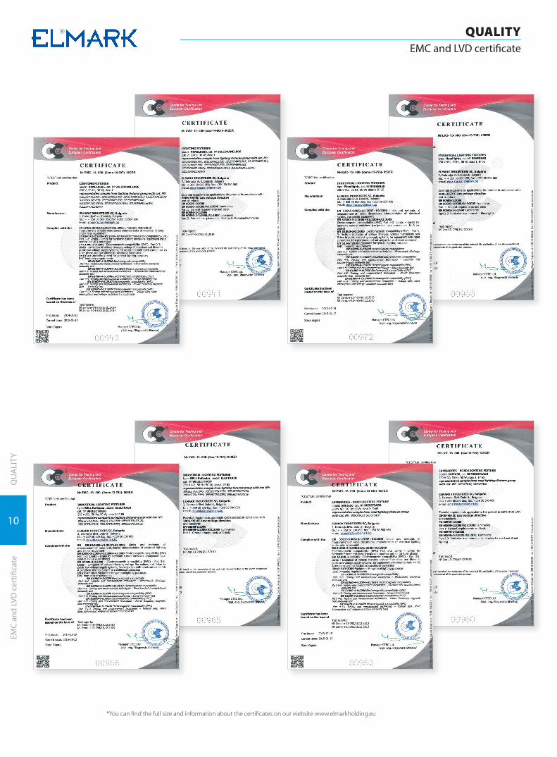
QUALITY EMC and LVD certificate
QU
ALI
TYEM
C an
d LV
D c
ertifi
cate
*You can find the full size and information about the certificates on our website www.elmarkholding.eu

11
QUALITY EMC and LVD certificate
QU
ALI
TYEM
C an
d LV
D c
ertifi
cate
*You can find the full size and information about the certificates on our website www.elmarkholding.eu
CIRCUIT BREAKERS
CIRCUIT BREAKERS

Miniature circuit breakers (MCB) | 14
Auxiliary devices for circuit breakers | 25
High power safety devices and isolating switches | 26
Switch disconnectors ISS | 31
Isolating switches ISS2 | 32
Manual switching to reserve series EQ 2M | 33
Dual power change-over switch | 34
Moulded case circuit breakers | 35
Moulded case circuit breakers with lock | 37
Moulded case circuit breakers | 39
Moulded case circuit breaker with ELCB | 40
Moulded case circuit breaker DW1 series | 42
Auxiliary devices for мoulded case circuit breakers | 43
14
CIRCUIT BREAKERSMiniature circuit breakers (MCB)
CIRC
UIT
BRE
AKE
RSM
inia
ture
circ
uit b
reak
ers
(MCB
)
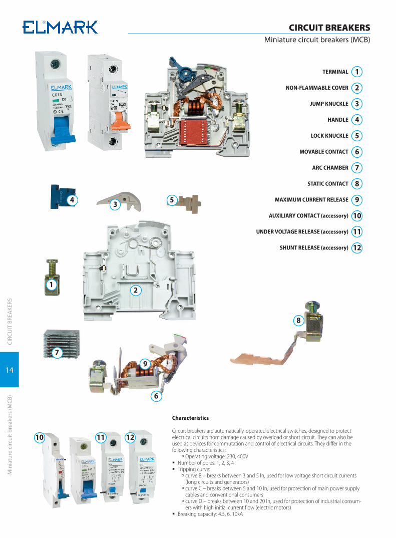
TERMINAL
NON-FLAMMABLE COVER
JUMP KNUCKLE
HANDLE
LOCK KNUCKLE
MOVABLE CONTACT
ARC CHAMBER
STATIC CONTACT
MAXIMUM CURRENT RELEASE
AUXILIARY CONTACT (accessory)
UNDER VOLTAGE RELEASE (accessory)
SHUNT RELEASE (accessory)
1
2
3
4
5
6
7
8
9
10
11
12
Characteristics
Circuit breakers are automatically-operated electrical switches, designed to protect electrical circuits from damage caused by overload or short circuit. They can also be used as devices for commutation and control of electrical circuits. They differ in the following characteristics:
à Operating voltage: 230, 400V � Number of poles: 1, 2, 3, 4 � Tripping curve:
à curve B – breaks between 3 and 5 In, used for low voltage short circuit currents (long circuits and generators)
à curve C – breaks between 5 and 10 In, used for protection of main power supply cables and conventional consumers
à curve D – breaks between 10 and 20 In, used for protection of industrial consum-ers with high initial current flow (electric motors)
� Breaking capacity: 4.5, 6, 10kA
10
7
11 12
9
8
6
54 3
21

15
CIRCUIT BREAKERSMiniature circuit breakers (MCB)
CIRC
UIT
BRE
AKE
RSM
inia
ture
circ
uit b
reak
ers
(MCB
)
Miniature circuit breakers (MCB) C40N*for industrial usage, 3 years warranty7 YEAR
WARRANTY
Functions: � protection of the electrical circuits from overload
or short circuits of the outer circuit � it can be used as a device for commutation and
control of electrical circuits � in combination with auxiliary devices it allows
remote control, commutation or indication of the protected circuit
� for mounting in residential and industrial buildings � for mounting at a distance from the transformer
post from 150 to 850 m � allows protection of consumers generating short
circuit currents up to 4500 A
Technical data: � Rated voltage: 230/400V; 50/60Hz � Breaking capacity (cycle O-CO) in accordance with
standard EN 60 898-1: 4500A � Rated breaking capacity Ics= 75% Icu � Isolating voltage:≥2000V � Electrical wear resistance (number of cycles): 4000 � Mechanical (number of cycles): 20000 � Class of current limiting:3 � IP code: IP>20 � Tripping:
à C – the maximum current release breaks be-tween 5 and 10 In; used to protect main power supply cables and conventional consumers
� Joining terminal: flat (tunnel) screw terminal with composition 1.5 coldly draw-plated plane Q235– A
� Plastic box – not keeping the burning material nylon PA66, UV rays wear resistance
� Box permitivity strength: >18MV/m � Abnormal heating wear resistance and fire of the
outer parts: 960°C / 3s � Maximum current release containing:
à copper coil - composition: pure copper T2 type à resistance: from 0.6 to 180m à welding effort: <150 000 N/mm à bimetal plate – composition: 5J158 to TB180 depending on the current
à thickness: 0.6mm (up to 40A) and 0.8mm (up to 63A)
à magnetic core – composition: coldly draw-plated metal wire (1Gr18Ni9)
à thickness: 1.15 to 2.24μm à drawing effort: from 200 to 400N/mm à contact head of the movable contact – compo-sition: silver graphite CAg(5)
à dimension 3x3x0.8 (up to 40A) and 4x4x0.8 (up to 63A)
à static contact – composition: pure copper T2Y2 à composition of the contact head: silver graph-ite CAg(5)
� Power supply (conducting) à power supply busbar 1P63, 2P63, 3P63 à rigid conductors up to 25 mm à flexible conductors up to 16 mm
� Tightening moment:1.33Nm
Mounting: � vertical � DIN-rail � for mounting in housing or industrial environment
without serious interference � ambient temperature: -5°C to + 65°C±2° C
Documents corresponding to the product:Standard EN60898-1EN60947-2
С4xNnumber of poles (1,2,3) breaking capacity in (kA) tripping curve Crated current in (A)tripping curve С
C x
Dimensions (mm)
C D1 D2 D3 H1
5 40 65 72 78
H2 W1 W2 W3 W4
45 18 36 54 72 1P 2P 3P
16
CIRCUIT BREAKERSMiniature circuit breakers (MCB)
CIRC
UIT
BRE
AKE
RSM
inia
ture
circ
uit b
reak
ers
(MCB
)
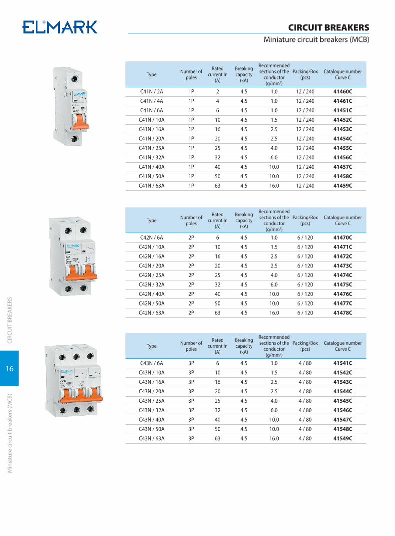
Type Number of poles
Rated current In
(A)
Breaking capacity
(kA)
Recommended sections of the
conductor (g/mm2)
Packing/Box (pcs)
Catalogue numberCurve C
C41N / 2A 1P 2 4.5 1.0 12 / 240 41460С
C41N / 4A 1P 4 4.5 1.0 12 / 240 41461С
C41N / 6A 1P 6 4.5 1.0 12 / 240 41451С
C41N / 10A 1P 10 4.5 1.5 12 / 240 41452С
C41N / 16A 1P 16 4.5 2.5 12 / 240 41453С
C41N / 20A 1P 20 4.5 2.5 12 / 240 41454С
C41N / 25A 1P 25 4.5 4.0 12 / 240 41455С
C41N / 32A 1P 32 4.5 6.0 12 / 240 41456С
C41N / 40A 1P 40 4.5 10.0 12 / 240 41457С
C41N / 50A 1P 50 4.5 10.0 12 / 240 41458С
C41N / 63A 1P 63 4.5 16.0 12 / 240 41459С
Type Number of poles
Rated current In
(A)
Breaking capacity
(kA)
Recommended sections of the
conductor (g/mm2)
Packing/Box (pcs)
Catalogue numberCurve C
C42N / 6A 2P 6 4.5 1.0 6 / 120 41470С
C42N / 10A 2P 10 4.5 1.5 6 / 120 41471С
C42N / 16A 2P 16 4.5 2.5 6 / 120 41472С
C42N / 20A 2P 20 4.5 2.5 6 / 120 41473С
C42N / 25A 2P 25 4.5 4.0 6 / 120 41474С
C42N / 32A 2P 32 4.5 6.0 6 / 120 41475С
C42N / 40A 2P 40 4.5 10.0 6 / 120 41476С
C42N / 50A 2P 50 4.5 10.0 6 / 120 41477С
C42N / 63A 2P 63 4.5 16.0 6 / 120 41478С
Type Number of poles
Rated current In
(A)
Breaking capacity
(kA)
Recommended sections of the
conductor (g/mm2)
Packing/Box (pcs)
Catalogue numberCurve C
C43N / 6A 3P 6 4.5 1.0 4 / 80 41541С
C43N / 10A 3P 10 4.5 1.5 4 / 80 41542С
C43N / 16A 3P 16 4.5 2.5 4 / 80 41543С
C43N / 20A 3P 20 4.5 2.5 4 / 80 41544С
C43N / 25A 3P 25 4.5 4.0 4 / 80 41545С
C43N / 32A 3P 32 4.5 6.0 4 / 80 41546С
C43N / 40A 3P 40 4.5 10.0 4 / 80 41547С
C43N / 50A 3P 50 4.5 10.0 4 / 80 41548С
C43N / 63A 3P 63 4.5 16.0 4 / 80 41549С
17
CIRCUIT BREAKERSMiniature circuit breakers (MCB)
CIRC
UIT
BRE
AKE
RSM
inia
ture
circ
uit b
reak
ers
(MCB
)
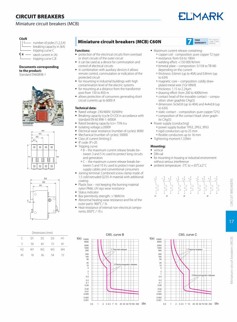
Miniature circuit breakers (MCB) C60N*for industrial usage, 3 years warranty7 YEAR
WARRANTY
Functions: � protection of the electrical circuits from overload
or short circuits of the outer circuit � it can be used as a device for commutation and
control of electrical circuits � in combination with auxiliary devices it allows
remote control, commutation or indication of the protected circuit
� for mounting in industrial buildings with high contamination level of the electric systems
� for mounting at a distance from the transformer post from 150 to 850 m
� allows protection of consumers generating short circuit currents up to 6000 A
Technical data: � Rated voltage: 230/400V; 50/60Hz � Breaking capacity (cycle O-CO) in accordance with
standard EN 60 898-1: 6000A � Rated breaking capacity Ics= 75% Icu � Isolating voltage:≥2000V � Electrical wear resistance (number of cycles): 8000 � Mechanical (number of cycles): 50000 � Class of current limiting:3 � IP code: IP>20 � Tripping curve:
à B – the maximum current release breaks be-tween 3 and 5 In; used to protect long circuits and generators
à C – the maximum current release breaks be-tween 5 and 10 In; used to protect main power supply cables and conventional consumers
� Joining terminal: Combined screw clamp made of 1.5 cold extruded Q235-A material with additional coating
� Plastic box – not keeping the burning material nylon PA66, UV rays wear resistance
� Status indicator � Box permitivity strength: >18MV/m � Abnormal heating wear resistance and fire of the
outer parts: 960°C / 3s � Heat resistance of internal non-electrical compo-
nents: 850°С / 10 s
� Maximum current release containing: à copper coil - composition: pure copper T2 type à resistance: from 0.6 to 180m à welding effort: <150 000 N/mm à bimetal plate – composition: 5J158 to TB180 depending on the current
à thickness: 0.6mm (up to 40A) and 0.8mm (up to 63A)
à magnetic core – composition: coldly draw-plated metal wire (1Gr18Ni9)
à thickness: 1.15 to 2.24μm à drawing effort: from 200 to 400N/mm à contact head of the movable contact – compo-sition: silver graphite CAg(5)
à dimension 3x3x0.8 (up to 40A) and 4x4x0.8 (up to 63A)
à static contact – composition: pure copper T2Y2 à composition of the contact head: silver graph-ite CAg(5)
� Power supply (conducting) à power supply busbar 1P63, 2P63, 3P63 à rigid conductors up to 25 mm à flexible conductors up to 16 mm
� Tightening moment:1.33Nm
Mounting: � vertical � DIN-rail � for mounting in housing or industrial environment
without serious interference � ambient temperature: -5°C to + 65°C±2° C
1P 2P 3P 4P
Documents corresponding to the product:Standard EN60898-1
С6xNnumber of poles (1,2,3,4) breaking capacity in (kA) tripping curve Crated current in (A)tripping curve С,B
C x
Dimensions (mm)
C D1 D2 D3 H1
5 50 65 72 81
H2 W1 W2 W3 W4
45 18 36 54 72
18
CIRCUIT BREAKERSMiniature circuit breakers (MCB)
CIRC
UIT
BRE
AKE
RSM
inia
ture
circ
uit b
reak
ers
(MCB
)
Type Number of poles
Rated current In (A)
Breaking capacity
(kA)
Recommendedsections of the
conductors (g/mm2)
Packing/Box (pcs)
Catalogue numberCurve C
Catalogue numberCurve B
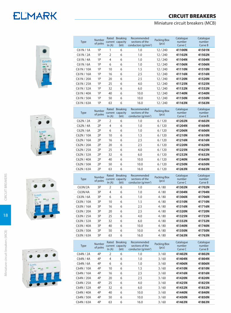
C61N / 1A 1P 1 6 1.0 12 / 240 41100N 41501NC61N / 2A 1P 2 6 1.0 12 / 240 41102N 41502NC61N / 4A 1P 4 6 1.0 12 / 240 41104N 41504NC61N / 6A 1P 6 6 1.0 12 / 240 41106N 41506N
C61N / 10A 1P 10 6 1.5 12 / 240 41110N 41510NC61N / 16A 1P 16 6 2.5 12 / 240 41116N 41516NC61N / 20A 1P 20 6 2.5 12 / 240 41120N 41520NC61N / 25A 1P 25 6 4.0 12 / 240 41125N 41525NC61N / 32A 1P 32 6 6.0 12 / 240 41132N 41532NC61N / 40A 1P 40 6 10.0 12 / 240 41140N 41540NC61N / 50A 1P 50 6 10.0 12 / 240 41150N 41550NC61N / 63A 1P 63 6 16.0 12 / 240 41163N 41563N
Type Number of poles
Rated current In (A)
Breaking capacity
(kA)
Recommendedsections of the
conductor (g/mm2)
Packing/Box (pcs)
Catalogue numberCurve C
Catalogue numberCurve B
C62N / 2А 2P 2 6 1.0 6 / 120 41202N 41602NC62N / 4A 2P 4 6 1.0 6 / 120 41204N 41604NC62N / 6A 2P 6 6 1.0 6 / 120 41206N 41606N
C62N / 10A 2P 10 6 1.5 6 / 120 41210N 41610NC62N / 16A 2P 16 6 2.5 6 / 120 41216N 41616NC62N / 20A 2P 20 6 2.5 6 / 120 41220N 41620NC62N / 25A 2P 25 6 4.0 6 / 120 41225N 41625NC62N / 32A 2P 32 6 6.0 6 / 120 41232N 41632NC62N / 40A 2P 40 6 10.0 6 / 120 41240N 41640NC62N / 50A 2P 50 6 10.0 6 / 120 41250N 41650NC62N / 63A 2P 63 6 16.0 6 / 120 41263N 41663N
Type Number of poles
Rated current In (A)
Breaking capacity
(kA)
Recommendedsections of the
conductor (g/mm2)
Packing/Box (pcs)
Catalogue numberCurve C
Catalogue numberCurve B
C63N/2A 3P 2 6 1.0 4 / 80 41302N 41702NC63N/4A 3P 4 6 1.0 4 / 80 41304N 41704NC63N / 6A 3P 6 6 1.0 4 / 80 41306N 41706N
C63N / 10A 3P 10 6 1.5 4 / 80 41310N 41710NC63N / 16A 3P 16 6 2.5 4 / 80 41316N 41716NC63N / 20A 3P 20 6 2.5 4 / 80 41320N 41720NC63N / 25A 3P 25 6 4.0 4 / 80 41325N 41725NC63N / 32A 3P 32 6 6.0 4 / 80 41332N 41732NC63N / 40A 3P 40 6 10.0 4 / 80 41340N 41740NC63N / 50A 3P 50 6 10.0 4 / 80 41350N 41750NC63N / 63A 3P 63 6 16.0 4 / 80 41363N 41763N
Type Number of poles
Rated current In (A)
Breaking capacity
(kA)
Recommendedsections of the
conductor (g/mm2)
Packing/Box (pcs)
Catalogue numberCurve C
Catalogue numberCurve B
C64N / 2A 4P 2 6 1.0 3 / 60 41402N 41802NC64N / 4A 4P 4 6 1.0 3 / 60 41404N 41804NC64N / 6A 4P 6 6 1.0 3 / 60 41406N 41806N
C64N / 10A 4P 10 6 1.5 3 / 60 41410N 41810NC64N / 16A 4P 16 6 2.5 3 / 60 41416N 41816NC64N / 20A 4P 20 6 2.5 3 / 60 41420N 41820NC64N / 25A 4P 25 6 4.0 3 / 60 41425N 41825NC64N / 32A 4P 32 6 6.0 3 / 60 41432N 41832NC64N / 40A 4P 40 6 10.0 3 / 60 41440N 41840NC64N / 50A 4P 50 6 10.0 3 / 60 41450N 41850NC64N / 63A 4P 63 6 16.0 3 / 60 41463N 41863N

19
CIRCUIT BREAKERSMiniature circuit breakers (MCB)
CIRC
UIT
BRE
AKE
RSM
inia
ture
circ
uit b
reak
ers
(MCB
)
Miniature circuit breakers (MCB) C100L*for industrial usage, 3 years warranty7 YEAR
WARRANTY
Functions: � protection of the electrical circuits from overload
or short circuits of the outer circuit � it can be used as a device for commutation and
control of electrical circuits � in combination with auxiliary devices it allows
remote control, commutation or indication of the protected circuit
Technical data: � Rated voltage: 230/400V; 50/60Hz � Breaking capacity (cycle O-CO) in accordance with
standard EN 60 898-1: 10000A � Rated breaking capacity Ics= 75% Icu � Isolating volatage:≥2000V, 1 min at impulse wave
1.2/50μs � Electrical wear resistance (number of cycles):≥4000
� Mechanical wear resistance (number of cycles): ≥20000
� Class of current limiting:3 � IP code: IP>20 � Tripping curve: C
Mounting: � vertical � DIN-rail � possibility for labeling
1P 2P 3P
Documents corresponding to the product:Standard EN60898-1EN60947-2
С10xLnumber of poles (1,2,3) breaking capacity in (kA) tripping curve Crated current in (A)tripping curve С
C x
Type Number of poles
Rated current In
(A)
Breaking capacity
(kA)
Recommendedsections of the
conductors (g/mm2)
Packing/Box (pcs)
Catalogue numberCurve C
C101L/6A 1P 6 10 1.0 12 / 240 41101C101L/10A 1P 10 10 1.5 12 / 240 41103C101L/16A 1P 16 10 2.5 12 / 240 41105C101L/20A 1P 20 10 2.5 12 / 240 41107C101L/25A 1P 25 10 4.0 12 / 240 41108C101L/32A 1P 32 10 6.0 12 / 240 41109C101L/40A 1P 40 10 10.0 12 / 240 41111C101L/50A 1P 50 10 10.0 12 / 240 41112C101L/63A 1P 63 10 16.0 12 / 240 41113
Type Number of poles
Rated current In
(A)
Breaking capacity
(kA)
Recommendedsections of the
conductors (g/mm2)
Packing/Box (pcs)
Catalogue numberCurve C
C102L/6A 2P 6 10 1.0 6/120 41201C102L/10A 2P 10 10 1.5 6/120 41203C102L/16A 2P 16 10 2.5 6/120 41205C102L/20A 2P 20 10 2.5 6/120 41207C102L/25A 2P 25 10 4.0 6/120 41208C102L/32A 2P 32 10 6.0 6/120 41209C102L/40A 2P 40 10 10.0 6/120 41211C102L/50A 2P 50 10 10.0 6/120 41212C102L/63A 2P 63 10 16.0 6/120 41213
Type Number of poles
Rated current In
(A)
Breaking capacity
(kA)
Recommendedsections of the
conductors (g/mm2)
Packing/Box (pcs)
Catalogue numberCurve C
C103L/6A 3P 6 10 1.0 4 / 80 41301C103L/10A 3P 10 10 1.5 4 / 80 41303C103L/16A 3P 16 10 2.5 4 / 80 41305C103L/20A 3P 20 10 2.5 4 / 80 41307C103L/25A 3P 25 10 4.0 4 / 80 41308C103L/32A 3P 32 10 6.0 4 / 80 41309C103L/40A 3P 40 10 10.0 4 / 80 41311C103L/50A 3P 50 10 10.0 4 / 80 41312C103L/63A 3P 63 10 16.0 4 / 80 41313

20
CIRCUIT BREAKERSMiniature circuit breakers (MCB)
CIRC
UIT
BRE
AKE
RSM
inia
ture
circ
uit b
reak
ers
(MCB
)
Miniature circuit breakers (MCB) C100M*for industrial usage, 3 years warranty7 YEAR
WARRANTY
Functions: � protection of the electrical circuits from overload
or short circuits of the outer circuit � it can be used as a device for commutation and
control of electrical circuits � in combination with auxiliary devices it allows
remote control, commutation or indication of the protected circuit
Technical data: � Rated voltage: 230/400V; 50/60Hz � Breaking capacity (cycle O-CO) in accordance with
standard EN 60 898-1: 10000A � Rated breaking capacity Ics= 75% Icu � Isolating volatage:≥2000V � Electrical wear resistance (number of cycles):≥4000 � Mechanical wear resistance (number of cy-
cles):≥20000 � Class of current limiting:3 � IP code: IP>20 � Tripping curve: C,D � Joining terminal: flat (tunnel) screw terminal with
composition 1.5 coldly draw-plated plane Q235 – A
� Plastic box – not keeping the burning material nylon PA66, UV rays wear resistance
� Box permitivity strength: >18MV/m � Abnormal heating wear resistance and fire of the
outer parts: 960°C / 3s � Maximum current release containing:
à copper coil - composition: pure copper T2 type à resistance: from 148 to 230m à welding effort: <400 N/ à bimetal plate – composition: TB180/0.5
à thickness: 0.8mm à magnetic core – composition: coldly draw-plated metal wire (1Gr18Ni9)
à thickness: 1.15 to 2.24μm à drawing effort: 20N/mm2
à contact head of the movable contact – compo-sition: silver graphite CAg(5)
à dimension 6x6x1 à static contact – composition: pure copper T2Y2 à composition of the contact head: silver graph-ite CAg(5)
� Power supply (conducting) à power supply busbar à rigid conductors up to 50 à flexible conductors up to 35
� Tightening moment:1.33Nm
Mounting: � vertical � DIN-rail � possibility for labeling � for mounting in industrial environment � ambient temperature: -5°C to + 65°C±2° C
1P 2P 3P 4P
Documents corresponding to the product:Standard EN60898-1EN 60947-2
С100M constructive seriesnumber of poles (1;2;3;4)
rated currenttripping curve С, D
D x
Dimensions (mm)
C D1 D2 D3 H1
5 50 65 74 45
H2 W1 W2 W3 W4
81 27 54 81 108

21
CIRCUIT BREAKERSMiniature circuit breakers (MCB)
CIRC
UIT
BRE
AKE
RSM
inia
ture
circ
uit b
reak
ers
(MCB
)
Type Number of poles
Rated current In (A)
Breaking capacity (kA) Packing/Box (pcs) Catalogue number
Curve CCatalogue number
Curve D
C100M 1P 80 10 9 / 180 41180 41180D
C100M 1P 100 10 9 / 180 41190 41190D
C100M 1P 125 10 9 / 180 41195 41195D
Type Number of poles
Rated current In (A)
Breaking capacity (kA) Packing/Box (pcs) Catalogue number
Curve CCatalogue number
Curve D
C100M 2P 80 10 6 / 120 41280 41281
C100M 2P 100 10 6 / 120 41290 41291
Type Number of poles
Rated current In (A)
Breaking capacity (kA) Packing/Box (pcs) Catalogue number
Curve CCatalogue number
Curve D
C100M 3P 80 10 4 / 60 41380 41381
C100M 3P 100 10 4 / 60 41390 41391
Type Number of poles
Rated current In (A)
Breaking capacity (kA) Packing/Box (pcs) Catalogue number
Curve CCatalogue number
Curve D
C100M 4P 80 10 3 / 60 41480 41481
C100M 4P 100 10 3 / 60 41490 41491
22
CIRCUIT BREAKERSMiniature circuit breakers (MCB)
CIRC
UIT
BRE
AKE
RSM
inia
ture
circ
uit b
reak
ers
(MCB
)
Documents corresponding to the product:Standard EN60898-1EN60898-2
C6xDCnumber of poles (1,2) breaking capacity in (kA) tripping curve Crated current in (A)tripping curve С
C x
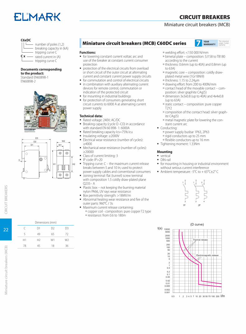
Miniature circuit breakers (MCB) C60DC series *for industrial usage, 3 years warranty7 YEAR
WARRANTY
Functions: � for lowering constant current voltaic arc and
use of the breaker at constant current consumer protection
� protection of the electrical circuits from overload or short circuit of the outer circuit at alternating current and constant current power supply circuits
� for commutation and control of electrical circuits � in combination with auxiliary alternating current
devices for remote control, commutation or indication of the protected circuit
� for mounting in industrial buildings � for protection of consumers generating short
circuit currents to 6000 A at alternating current power supply
Technical data: � Rated voltage: 240V; AC/DC � Breaking capacity (cycle O -CO) in accordance
with standard EN 60 898- 1: 6000A � Rated breaking capacity Ics=75% Icu � Insulating voltage: ≥2000V � Electrical wear resistance (number of cycles):
≥4000 � Mechanical wear resistance (number of cycles):
≥20000 � Class of current limiting: 3 � IP code: IP>20 � Tripping curve: C – the maximum current release
breaks between 5 and 10 In; used to protect power supply cables and conventional consumers
� Joining terminal: flat (tunnel) screw terminal with composition 1.5 coldly draw-plated plane Q235– A
� Plastic box – not keeping the burning material nylon PA66, UV rays wear resistance
� Box permitivity strength: >18MV/m � Abnormal heating wear resistance and fire of the
outer parts: 960°C / 3s � Maximum current release containing:
à copper coil - composition: pure copper T2 type à resistance: from 0.6 to 180m
à welding effort: <150 000 N/mm à bimetal plate – composition: 5J158 to TB180 according to the current
à thickness: 0.6mm (up to 40A) and 0.8mm (up to 63A)
à magnetic core – composition: coldly draw-plated metal wire (1Gr18Ni9)
à thickness: 1.15 to 2.24μm à drawing effort: from 200 to 400N/mm à contact head of the movable contact – com-position: silver graphite CAg(5)
à dimension 3x3x0.8 (up to 40A) and 4x4x0.8 (up to 63A)
à static contact – composition: pure copper T2Y2
à composition of the contact head: silver graph-ite CAg(5)
à metal magnetic plate for lowering the con-stant current arc
� Conducting: à power supply busbar 1P63, 2P63 à rigid conductors up to 25 mm à flexible conductors up to 16 mm
� Tightening moment: 1.33Nm
Mounting � vertical � DIN-rail � for mounting in housing or industrial environment
without serious current interference � Ambient temperature: -5°C to + 65°C±2° C
1P 2P
Dimensions (mm)
C D1 D2 D3
5 49 65 72
H1 H2 W1 W2
78 45 18 36

23
CIRCUIT BREAKERSMiniature circuit breakers (MCB)
CIRC
UIT
BRE
AKE
RSM
inia
ture
circ
uit b
reak
ers
(MCB
)
Type Number of poles
Rated current In
(A)
Breaking capacity
(kA)
Recommendedsections of the
conductor (g/mm2)
Packing/Box (pcs)
Catalogue numberCurve C
61DC / 1A 1P 1 6 1.0 12 / 240 41164
61DC / 2A 1P 2 6 1.0 12 / 240 41165
61DC / 4A 1P 4 6 1.0 12 / 240 41166
61DC / 6A 1P 6 6 1.0 12 / 240 41167
61DC / 10A 1P 10 6 1.5 12 / 240 41168
61DC / 16A 1P 16 6 2.5 12 / 240 41169
61DC / 20A 1P 20 6 2.5 12 / 240 41170
61DC / 25A 1P 25 6 4.0 12 / 240 41171
61DC / 32A 1P 32 6 6.0 12 / 240 41172
61DC / 40A 1P 40 6 10.0 12 / 240 41173
61DC / 50A 1P 50 6 10.0 12 / 240 41174
61DC / 63A 1P 63 6 16.0 12 / 240 41175
Type Number of poles
Rated current In
(A)
Breaking capacity
(kA)
Recommendedsections of the
conductor (g/mm2)
Packing/Box (pcs)
Catalogue numberCurve C
62DC / 2A 2P 2 6 1.0 6 / 120 41176
62DC / 4A 2P 4 6 1.0 6 / 120 41177
62DC / 6A 2P 6 6 1.0 6 / 120 41178
62DC / 10A 2P 10 6 1.5 6 / 120 41179
62DC / 16A 2P 16 6 2.5 6 / 120 41181
62DC / 20A 2P 20 6 2.5 6 / 120 41182
62DC / 25A 2P 25 6 4.0 6 / 120 41183
24
CIRCUIT BREAKERSMiniature circuit breakers (MCB)
CIRC
UIT
BRE
AKE
RSM
inia
ture
circ
uit b
reak
ers
(MCB
)
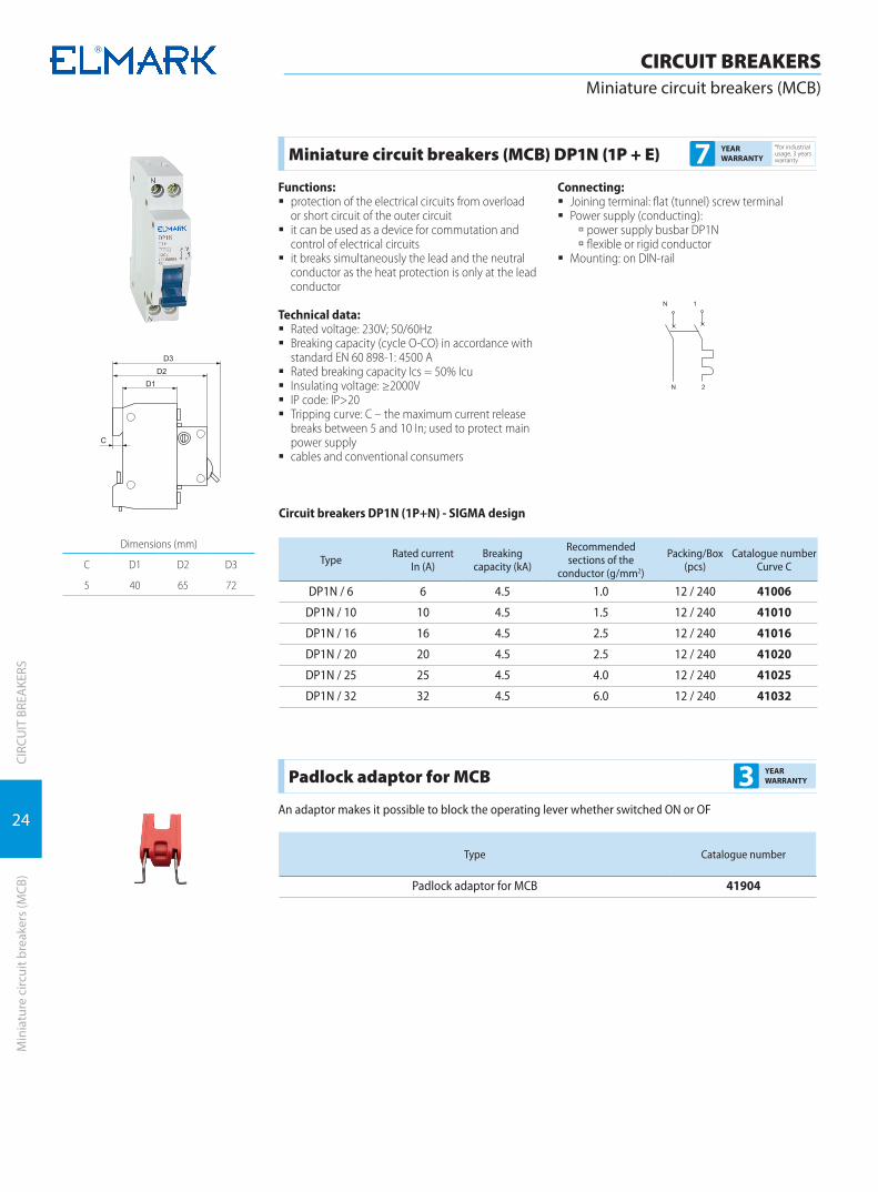
Miniature circuit breakers (MCB) DP1N (1P + E)*for industrial usage, 3 years warranty7 YEAR
WARRANTY
Functions: � protection of the electrical circuits from overload
or short circuit of the outer circuit � it can be used as a device for commutation and
control of electrical circuits � it breaks simultaneously the lead and the neutral
conductor as the heat protection is only at the lead conductor
Technical data: � Rated voltage: 230V; 50/60Hz � Breaking capacity (cycle O-CO) in accordance with
standard EN 60 898-1: 4500 A � Rated breaking capacity Ics = 50% Icu � Insulating voltage: ≥2000V � IP code: IP>20 � Tripping curve: C – the maximum current release
breaks between 5 and 10 In; used to protect main power supply
� cables and conventional consumers
Connecting: � Joining terminal: flat (tunnel) screw terminal � Power supply (conducting):
à power supply busbar DP1N à flexible or rigid conductor
� Mounting: on DIN-rail
Dimensions (mm)
C D1 D2 D3
5 40 65 72
Circuit breakers DP1N (1P+N) - SIGMA design
Type Rated current In (A)
Breaking capacity (kA)
Recommendedsections of the
conductor (g/mm2)
Packing/Box (pcs)
Catalogue numberCurve C
DP1N / 6 6 4.5 1.0 12 / 240 41006
DP1N / 10 10 4.5 1.5 12 / 240 41010
DP1N / 16 16 4.5 2.5 12 / 240 41016
DP1N / 20 20 4.5 2.5 12 / 240 41020
DP1N / 25 25 4.5 4.0 12 / 240 41025
DP1N / 32 32 4.5 6.0 12 / 240 41032
Padlock adaptor for MCB 3 YEAR WARRANTY
An adaptor makes it possible to block the operating lever whether switched ON or OF
Type Catalogue number
Padlock adaptor for MCB 41904

25
CIRC
UIT
BRE
AKE
RSAu
xilia
ry d
evic
es fo
r circ
uit b
reak
ers
CIRCUIT BREAKERSAuxiliary devices for circuit breakers
Type designation:МN - constructive seriesnumber of poles - 1Documents correspondingto the product:Standard EN60898-1
Type designation:МX - constructive seriesnumber of poles - 1Documents correspondingto the product:Standard EN60898-1
Type designation:OF - constructive seriesnumber of poles - 1Documents correspondingto the product:Standard EN60898-1
Combined voltage circuit-breaker МN2*for industrial usage, 3 years warranty7 YEAR
WARRANTY
Functions: � when the voltage is reduced below 170V operation
is initiated and the automatic switch is turned off � when the voltage is increased above 280V opera-
tion is initiated and the automatic switch is turned off
� allows manual turning on of the switch after pow-ering is restored
� indication of the position of the deviceTechnical characteristics:
� Rated voltage: 230V; 50/60Hz � Insulation voltage: ≥2000V
� IP code: IP>20Connection method:
� Double connector: flat (tunnel) screw connector � Feeding (conducting):
à flexible conductors up to 1.5mm2
� Tightening moment of the screw: 1.33NmMounting:
� vertical, by means of two pins attached to the rivets of the circuit-breaker, while the operating mechanism is connected to the switching off mechanism of the circuit breaker after the sealing lid is demounted
Type Rated voltage Type breaker Packing/Box (pcs) Catalogue number
ELMARK MN 2 60 230V С60 12 / 240 41909
Shunt release MX (independent release)*for industrial usage, 3 years warranty7 YEAR
WARRANTY
Functions: � remote circuit breaker switching off at voltage feed � allows manual switching on of the breaker at volt-
age recovery � indication of the device’s location
Technical data: � Rated voltage: 230V; 50/60Hz � Isolating voltage: ≥2000V � IP code: IP>20
Connecting: � Joining terminal: flat (tunnel) screw terminal � Power supply (conducting):
à flexible conductors up to 1.5mm2
� Tightening moment: 1.33Nm � The power supply of the release is accomplished at
the outlet of the breakerMounting:
� vertical, clamps with two pins to the breaker’s rivets and the executive mechanism is joined up to the switching mechanism of the breaker after dismounting the seal cover
Type Rated voltage Type breaker Packing/Box (pcs) Catalogue number
ELMARK MX 60 230V С60 12 / 240 41902
Auxiliary contact OF*for industrial usage, 3 years warranty7 YEAR
WARRANTY
Functions: � at circuit breaker switching off it sends a signal to
the control or signalization system � indication of the location of the auxiliary contact
and the breakerTechnical data:
� Rated voltage: 230V � Isolating voltage: ≥2000V � IP code: IP>20
Connecting: � Joining terminal: flat (tunnel) screw terminal � Power supply (conducting): - flexible conductors up
to 1.5mmMounting:
� vertical, clamps with two pins to breaker’s rivets, and the executive mechanism is joined up to the switching mechanism of the breaker after dismounting the seal cover
Type Rated voltage Type breaker Packing/Box (pcs) Catalogue number
ELMARK OF 60 230V С60 12 / 240 41901
ELMARK SD100 230V C60 12 / 240 41905

26
CIRC
UIT
BRE
AKE
RSH
igh
pow
er s
afet
y de
vice
s an
d is
olat
ing
switc
hes
CIRCUIT BREAKERSHigh power safety devices and isolating switches
Base typeOverall dimensions (mm)
А1 A2 A3 B1 B2 C1 C2 Ød
SIST00 25 100 120 - 30 25 60 7.5
SIST 0 25 150 170 - 30 37 72 7.5
SIST1 25 175 200 30 58 38 84 10.5
SIST2 25 200 225 30 60 38 100 10.5
SIST3 25 210 250 30 60 40 105 10.5
Documents corresponding to the product: Standard EN 60269-1
Bases for high power safety devices 3 YEAR WARRANTY
The series bases for high power safety device is manufactured of permitivity alloy with mounted contact jaws of electrolytic copper supplied with special springs for contact compression and easy fuse links taking out. All current leading parts are connected to inlet outlet terminals with bolts; the terminals also end with bolts, to which the power supply conductors are connected. The bases are offered in five type sizes corresponding to the five types of fuse links.
Base type Fuse link typeRated current
(А)Rated voltage
Un (V)Weight
(gr)Packing / Box (pcs)
Catalogue number
SIST00 NТ 00 up to 160 600 193 5 / 120 12001
SISP00 NT 00 up to 160 600 215 5 / 120 12001Р
Remark : Fuse bases SISP are made of porcelain
Base type Fuse link typeRated current
(А)Rated voltage
Un (V)Weight
(gr)Packing / Box (pcs)
Catalogue number
SIST0 NТ 0 up to 160 600 295 3 / 54 12010
SISP0 NT 0 up to 160 600 319 3 / 54 12010P
Remark : Fuse bases SISP are made of porcelain
Base type Fuse link typeRated current
(А)Rated voltage
Un (V)Weight
(gr)Packing / Box (pcs)
Catalogue number
SIST1 NТ 1 up to 250 600 550 3 / 36 12100
SISP1 NT 1 up to 250 600 550 3 / 36 12100P
Remark : Fuse bases SISP are made of porcelain
Base type Fuse link typeRated current
(А)Rated voltage
Un (V)Weight
(gr)Packing / Box (pcs)
Catalogue number
SIST2 NТ 2 up to 400 600 770 1 / 20 12200
SISP2 NT 2 up to 400 600 810 1 / 20 12200Р
Remark : Fuse bases SISP are made of porcelain
Base type Fuse link typeRated current
(А)Rated voltage
Un (V)Weight
(gr)Packing / Box (pcs)
Catalogue number
SIST3 NТ 3 up to 630 600 965 1 / 15 12300
SISP3 NT 3 up to 630 600 987 1 / 20 12300P
Remark : Fuse bases SISP are made of porcelain

27
CIRC
UIT
BRE
AKE
RSH
igh
pow
er s
afet
y de
vice
s an
d is
olat
ing
switc
hes
CIRCUIT BREAKERSHigh power safety devices and isolating switches
Documents corresponding to the product: Standard EN 60269-1EN 60269-2
Fuse links for high power safety device 3 YEAR WARRANTY
The series fuse links for high power safety devices is designed for short circuit protection. They are distinguished with high speed of operation and high reliability. The element is a ceramic (porcelain) body filled with fine quartz sand for voltaic arc lowering. In the ceramic body is mounted a fusible, specially profiled wafer connecting the current leading terminals. These terminals are manufactured of copper alloy with special nickel coating and have the form of knives to provide more contact surface. The fuse links correspond to “gL – gG” class which means that they are with common function and normal response time.NH Fuses
Two operating classes of NH Fuses are avail-able:
� Operating class gL/gG – general purpose, line protection, slow acting
Technical data: � Rated voltage: 500V � Rated short circuit current: 120 kAeff � IP code: IP 00 � Ambient temperature: -5 to +65°C � Altitude: up to 2000m
Base typeOverall dimensions (mm)
А B C D H
NT00 78 40 15 29 56.5
NT 0 125 68 15 29 56.5
NT1 135 68 21 48 62
NT 2 150 68 27 58 72
NT 3 150 68 33 67 84.5
NT00C 78 40 15 21 56,5
NT1C 135 68 21 29 62
NT2C 150 68 33 48 84,5
Type In (A) Un (V) Packing / Box (pcs) Catalogue number
NT00 16 500,600 3 / 120 10001NT00 25 500,600 3 / 120 10002NT00 32 500,600 3 / 120 10003NT00 40 500,600 3 / 120 10004NT00 50 500,600 3 / 120 10005NT00 63 500,600 3 / 120 10006NT00 80 500,600 3 / 120 10008NT00 100 500,600 3 / 120 10009NT00 125 500,600 3 / 120 10012NT00 160 500,600 3 / 120 10016
Type In (A) Un (V) Packing / Box (pcs) Catalogue number
NT0 16 500,600 3 / 90 10015NT0 25 500,600 3 / 90 10025NT0 32 500,600 3 / 90 10032NT0 40 500,600 3 / 90 10040NT0 50 500,600 3 / 90 10050NT0 63 500,600 3 / 90 10063NT0 80 500,600 3 / 90 10080NT0 100 500,600 3 / 90 10090NT0 125 500,600 3 / 90 10092NT0 160 500,600 3 / 90 10096
28
CIRC
UIT
BRE
AKE
RSH
igh
pow
er s
afet
y de
vice
s an
d is
olat
ing
switc
hes
CIRCUIT BREAKERSHigh power safety devices and isolating switches
Type In (A) Un (V) Packing / Box (pcs) Catalogue number
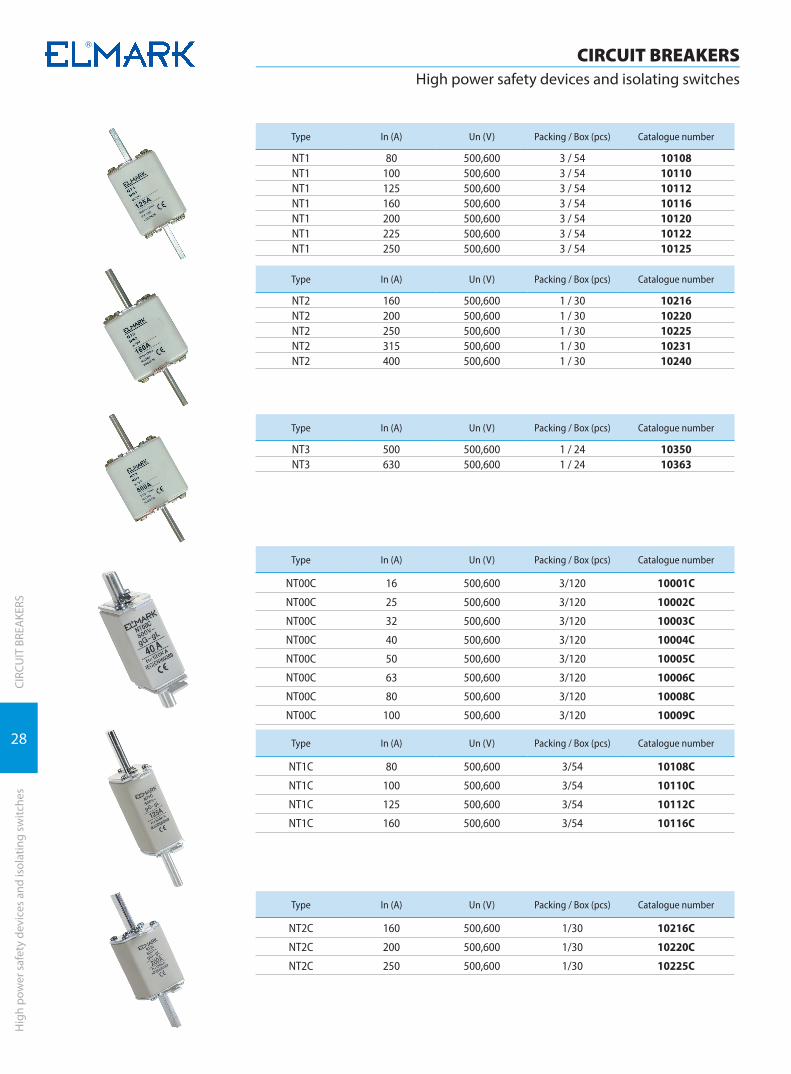
NT1 80 500,600 3 / 54 10108NT1 100 500,600 3 / 54 10110NT1 125 500,600 3 / 54 10112NT1 160 500,600 3 / 54 10116NT1 200 500,600 3 / 54 10120NT1 225 500,600 3 / 54 10122NT1 250 500,600 3 / 54 10125
Type In (A) Un (V) Packing / Box (pcs) Catalogue number
NT2 160 500,600 1 / 30 10216NT2 200 500,600 1 / 30 10220NT2 250 500,600 1 / 30 10225NT2 315 500,600 1 / 30 10231NT2 400 500,600 1 / 30 10240
Type In (A) Un (V) Packing / Box (pcs) Catalogue number
NT3 500 500,600 1 / 24 10350NT3 630 500,600 1 / 24 10363
Type In (A) Un (V) Packing / Box (pcs) Catalogue number
NT00C 16 500,600 3/120 10001C
NT00C 25 500,600 3/120 10002C
NT00C 32 500,600 3/120 10003C
NT00C 40 500,600 3/120 10004C
NT00C 50 500,600 3/120 10005C
NT00C 63 500,600 3/120 10006C
NT00C 80 500,600 3/120 10008C
NT00C 100 500,600 3/120 10009C
Type In (A) Un (V) Packing / Box (pcs) Catalogue number
NT1C 80 500,600 3/54 10108C
NT1C 100 500,600 3/54 10110C
NT1C 125 500,600 3/54 10112C
NT1C 160 500,600 3/54 10116C
Type In (A) Un (V) Packing / Box (pcs) Catalogue number
NT2C 160 500,600 1/30 10216C
NT2C 200 500,600 1/30 10220C
NT2C 250 500,600 1/30 10225C
29
CIRC
UIT
BRE
AKE
RSH
igh
pow
er s
afet
y de
vice
s an
d is
olat
ing
switc
hes
CIRCUIT BREAKERSHigh power safety devices and isolating switches
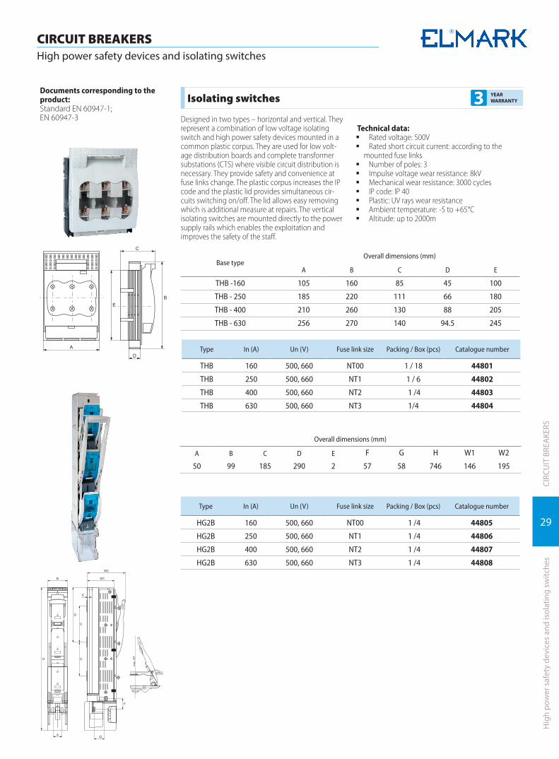
Base typeOverall dimensions (mm)
А B C D E
THB -160 105 160 85 45 100
THB - 250 185 220 111 66 180
THB - 400 210 260 130 88 205
THB - 630 256 270 140 94.5 245
Documents corresponding to the product: Standard EN 60947-1; EN 60947-3
Isolating switches 3 YEAR WARRANTY
Designed in two types – horizontal and vertical. They represent a combination of low voltage isolating switch and high power safety devices mounted in a common plastic corpus. They are used for low volt-age distribution boards and complete transformer substations (CTS) where visible circuit distribution is necessary. They provide safety and convenience at fuse links change. The plastic corpus increases the IP code and the plastic lid provides simultaneous cir-cuits switching on/off. The lid allows easy removing which is additional measure at repairs. The vertical isolating switches are mounted directly to the power supply rails which enables the exploitation and improves the safety of the staff.
Technical data: � Rated voltage: 500V � Rated short circuit current: according to the
mounted fuse links � Number of poles: 3 � Impulse voltage wear resistance: 8kV � Mechanical wear resistance: 3000 cycles � IP code: IP 40 � Plastic: UV rays wear resistance � Ambient temperature: -5 to +65°C � Altitude: up to 2000m
Type In (A) Un (V) Fuse link size Packing / Box (pcs) Catalogue number
THB 160 500, 660 NT00 1 / 18 44801
THB 250 500, 660 NT1 1 / 6 44802
THB 400 500, 660 NT2 1 /4 44803
THB 630 500, 660 NT3 1/4 44804
Type In (A) Un (V) Fuse link size Packing / Box (pcs) Catalogue number
HG2B 160 500, 660 NT00 1 /4 44805
HG2B 250 500, 660 NT1 1 /4 44806
HG2B 400 500, 660 NT2 1 /4 44807
HG2B 630 500, 660 NT3 1 /4 44808
G
Overall dimensions (mm)
А B C D E F G H W1 W2
50 99 185 290 2 57 58 746 146 195

30
CIRC
UIT
BRE
AKE
RSH
igh
pow
er s
afet
y de
vice
s an
d is
olat
ing
switc
hes
CIRCUIT BREAKERSHigh power safety devices and isolating switches
Documents corresponding to the product: Standard EN 60269-2; IEC269-2
Switch disconnectors 3 YEAR WARRANTY
The series of switch disconnectors are developed for short-circuit protection. They have a high speed of start and high reliability. They have a plastic body of non-flammable plastics adapted for mounting on a DIN rail, where a porcelain round plug, which is filled with fine quartz sand for extinguishing the electric arc. LED indicator is mounted on the front panel to show fuse link condition. In this ceramic body is mounted melting, specifically profiled plate, which connects the input power terminals. These terminals are produced from copper alloy with especially laid nickel layer and contact with the projecting bolts from the plastic body. There are offered two types of insertions according to the degree of quick opera-
tion: normally quickly operating ones – class “gG”. Suitable for DC system.Technical data:
� Rated voltage: 500V � Insulation voltage: >2500V � Rated current on short-circuit: 100 кА � Direct mounting to the load � Two insulated points to the load � IP code: IP 44 � Cross-section of the supply conductors:
up to 35mm2
� Environmental temperature: -5° to +65°С � Utization category: AC - 20B; DC - 20B � Altitude: up to 2000m
Overall dimensions
Base type Number of poles
Rated current
( А )
Type of the fuse
Base dimensions (mm) Packing / Box (pcs)
Catalogue numberA B W D E
1PRT18 - 32x 1P 32 xxG1038 37 82 18 60 78 12 / 240 10RT1831
1NRT18 - 32x 1P+N 32 xxG1038 37 82 36 60 78 12 / 240 10RT18311
2PRT18 - 32x 2P 32 xxG1038 37 82 36 60 78 12 / 240 10RT1832
3PRT18 - 32x 3P 32 xxG1038 37 82 54 60 78 12 / 240 10RT1833
3NRT18 - 32x 3P+N 32 xxG1038 37 82 72 60 78 12 / 240 10RT18331
1PRT18 - 63x 1P 63 xxG1451 37 105 27 80 110 6 / 108 10RT1861
1NRT18 - 63x 1P+N 63 xxG1451 37 105 54 80 110 6 / 108 10RT18611
2PRT18 - 63x 2P 63 xxG1451 37 105 54 80 110 6 / 108 10RT1862
3PRT18 - 63x 3P 63 xxG1451 37 105 81 80 110 6 / 108 10RT1863
3NRT18 - 63x 3P+N 63 xxG1451 37 105 108 80 110 6 / 108 10RT18631
Type of the fuseclass gG
Voltage( V )
Rated current ( А )
Size of the fuseA x ØB x C
Packing / Box (pcs) Catalogue number
01G1038 500 1 38xØ10.3x10mm 10 / 2000 10G10381
02G1038 500 2 38xØ10.3x10mm 10 / 2000 10G10382
04G1038 500 4 38xØ10.3x10mm 10 / 2000 10G10384
06G1038 500 6 38xØ10.3x10mm 10 / 2000 10G10386
10G1038 500 10 38xØ10.3x10mm 10 / 2000 10G103810
16G1038 500 16 38xØ10.3x10mm 10 / 2000 10G103816
20G1038 500 20 38xØ10.3x10mm 10 / 2000 10G103820
25G1038 500 25 38xØ10.3x10mm 10 / 2000 10G103825
32G1038 500 32 38xØ10.3x10mm 10 / 2000 10G103832
40G1451 500 40 51xØ14.3x12mm 10 / 1000 10G145140
50G1451 500 50 51xØ14.3x12mm 10 / 1000 10G145150
63G1451 500 63 51xØ14.3x12mm 10 / 1000 10G145163

31
CIRC
UIT
BRE
AKE
RS
CIRCUIT BREAKERSSwitch disconnectors ISS
Switc
h di
scon
nect
ors
ISS
Documents correspondingto the product:Standard EN 60947-3 and IEC947-3
Type Number of poles
Rated current In
(A)
Recommended sections of the
conductor (g/mm2)
Packing/Box (pcs)
Catalogue number
ISS 1P 40 10 12 / 240 41914
ISS 1P 63 16 12 / 240 41911
ISS 1P 80 25 12 / 240 41912
ISS 1P 100 35 12 / 240 41913
Type Number of poles
Rated current In
(A)
Recommended sections of the
conductor (g/mm2)
Packing/Box (pcs)
Catalogue number
ISS 2P 40 10 6 / 120 41924
ISS 2P 63 16 6 / 120 41921
ISS 2P 80 25 6 / 120 41922
ISS 2P 100 35 6 / 120 41923
Type Number of poles
Rated current In
(A)
Recommended sections of the
conductor (g/mm2)
Packing/Box (pcs)
Catalogue number
ISS 3P 20 2.5 4/80 41935
ISS 3P 32 6.0 4/80 41936
ISS 3P 40 10 4 / 80 41934
ISS 3P 63 16 4 / 80 41931
ISS 3P 80 25 4 / 80 41932
ISS 3P 100 35 4 / 80 41933
Type Number of poles
Rated current In
(A)
Recommended sections of the
conductor (g/mm2)
Packing/Box (pcs)
Catalogue number
ISS 4P 40 10 3 / 60 41944
ISS 4P 63 16 3 / 60 41941
ISS 4P 80 25 3 / 60 41942
ISS 4P 100 35 3 / 60 41943
Switch disconnectors ISS 20...100A series*for industrial usage, 3 years warranty5 YEAR
WARRANTY
Functions: � switching on/off heavy loaded electrical circuits � breaking of electrical circuits � can be used as a main breaker � it has no protective function
Technical data: � Rated voltage: 230/400V; 50/60Hz � Joining terminal: flat (tunnel) screw terminal � Connecting: power supply busbar, rigid or flexible conductors � Tightening moment: 1.33Nm � Isolating voltage: ≥500V � Electrical wear resistance (number of cycles): ≥10000 � Mechanical wear resistance (number of cycles): ≥20000 � IP code: IP>20 � Mounting: DIN-rail � Plastic material of UV rays � Ambient temperature: -20°C + 65°C
Dimensions (mm)
H1 H2 D1 D2 D3
81 45 50 65 76
W1 W2 W3 W3
17,5 35 52,5 70

32
CIRC
UIT
BRE
AKE
RSIs
olat
ing
switc
hes
ISS2
CIRCUIT BREAKERSIsolating switches ISS2
Documents correspondingto the product:Standard EN 60947-1EN 60947-3 and IEC 60947-6
Switch disconnectors ISS2 125...800A*for industrial usage, 3 years warranty5 YEAR
WARRANTY
The series three- and four-pole load switch discon-nectors ISS2 xxx are produced for mounting in main electrical boards for disconnection of the circuits, switching on of generators because of the fact they are not affected by the frequency variations. High mechanical strength and resistance to circulation. Simple and secure management. There is a possibility for the products to be produced with an window for visible disconnection.
Functions: � switching on and off of electrical circuits under load � disconnection of electrical circuits � used as main circuit-breaker � resistant to high voltages, to short circuits in the
protected circuit � it has no protective function
Technical features: � Rated voltage: not higher than 660V; 50/60Hz � Double connector: screw connection � Connection: solid or flexible conductors � Insulation voltage: ≥1000V � Resistance to impulse voltage: 8000V � Electrical endurance (number of cycles): ≥5 000 � Mechanical endurance (number of cycles): ≥10 000 � IP code: IP>20 � Mounting method: to a surface by means of bolts � Plastic resistant to UV raysPlastic resistant to UV rays � Ambient temperature: -20°÷65ºС
TypeDimensions (mm)
A B C D E J J1 K R S T Y
ISS2-125/3 140 135 125 27 73 120 120 65 20 25 3.5 25
ISS2-125/4 170 135 125 27 73 150 150 65 20 25 3.5 25
ISS2-160/3 140 135 125 27 73 120 120 65 20 25 3.5 25
ISS2-160/4 170 135 125 27 73 150 150 65 20 25 3.5 25
ISS2-250/3 180 170 138 35 86 160 160 90 25 30 3.5 25
ISS2-250/4 230 170 138 35 86 210 210 90 25 30 3.5 25
ISS2-400/3 230 240 165 50 110 210 210 140 32 40 5 37
ISS2-400/4 295 240 165 50 110 275 275 140 32 40 5 37
ISS2-630/3 230 260 165 50 110 210 210 140 40 50 6 37
ISS2-630/4 295 260 165 50 110 275 275 140 40 50 6 37
ISS2-800/3 378 312 240 50 140 353 353 175 60 56 8 48
ISS2-800/4 498 312 240 50 140 473 473 175 60 56 8 48
TypeRated
current In (A)
Maximum breaking
capacity Icu (A)
Tightening moment (Nm)
Packing/Box (pcs)
Catalogue number three-
pole
Catalogue number
four-pole
ISS2-125in 125 1250 6.5 1 / 12 41951 41961
ISS2-125out 125 1250 6.5 1 / 12 41952 41962
ISS2-160in 160 1250 6.5 1 / 12 41953 41963
ISS2-160out 160 1250 6.5 1 / 12 41954 41964
ISS2-250in 250 2000 10 1 / 6 41955 41965
ISS2-250out 250 2000 10 1 / 6 41956 41966
ISS2-400in 400 3200 14.5 1 / 2 41957 41967
ISS2-630in 630 4000 14.5 1 / 2 41958 41968
ISS2-800in 800 1000 27 1 / 2 41959 41969
Note: ISS2-xxx in – load circuit-breaker for mounting in the interior of a board ISS2 -xxx out – load circuit-breaker with an extended lever for mounting on the front panel of the board
33
CIRC
UIT
BRE
AKE
RS
CIRCUIT BREAKERSManual switching to reserve series EQ 2M
Man
ual s
witc
hing
to re
serv
e se
ries
EQ 2
M
Documents correspondingto the product:Standard EN 60947-1EN 60947-3 and IEC 60947-6
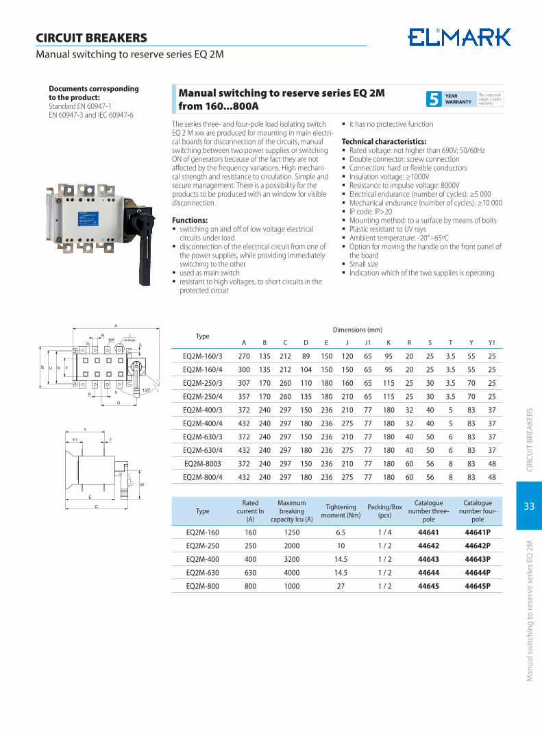
Manual switching to reserve series EQ 2M from 160...800A
*for industrial usage, 3 years warranty5 YEAR
WARRANTY
The series three- and four-pole load isolating switch EQ 2 M xxx are produced for mounting in main electri-cal boards for disconnection of the circuits, manual switching between two power supplies or switching ON of generators because of the fact they are not affected by the frequency variations. High mechani-cal strength and resistance to circulation. Simple and secure management. There is a possibility for the products to be produced with an window for visible disconnection.
Functions: � switching on and off of low voltage electrical
circuits under load � disconnection of the electrical circuit from one of
the power supplies, while providing immediately switching to the other
� used as main switch � resistant to high voltages, to short circuits in the
protected circuit
� it has no protective function
Technical characteristics: � Rated voltage: not higher than 690V; 50/60Hz � Double connector: screw connection � Connection: hard or flexible conductors � Insulation voltage: ≥1000V � Resistance to impulse voltage: 8000V � Electrical endurance (number of cycles): ≥5 000 � Mechanical endurance (number of cycles): ≥10 000 � IP code: IP>20 � Mounting method: to a surface by means of bolts � Plastic resistant to UV rays � Ambient temperature: -20°÷65ºС � Option for moving the handle on the front panel of
the board � Small size � Indication which of the two supplies is operating
TypeDimensions (mm)
A B C D E J J1 K R S T Y Y1
ЕQ2M-160/3 270 135 212 89 150 120 65 95 20 25 3.5 55 25
EQ2M-160/4 300 135 212 104 150 150 65 95 20 25 3.5 55 25
ЕQ2M-250/3 307 170 260 110 180 160 65 115 25 30 3.5 70 25
EQ2M-250/4 357 170 260 135 180 210 65 115 25 30 3.5 70 25
ЕQ2M-400/3 372 240 297 150 236 210 77 180 32 40 5 83 37
EQ2M-400/4 432 240 297 180 236 275 77 180 32 40 5 83 37
ЕQ2M-630/3 372 240 297 150 236 210 77 180 40 50 6 83 37
EQ2M-630/4 432 240 297 180 236 275 77 180 40 50 6 83 37
ЕQ2M-8003 372 240 297 150 236 210 77 180 60 56 8 83 48
EQ2M-800/4 432 240 297 180 236 275 77 180 60 56 8 83 48
TypeRated
current In (A)
Maximum breaking
capacity Icu (A)
Tightening moment (Nm)
Packing/Box (pcs)
Catalogue number three-
pole
Catalogue number four-
pole
ЕQ2M-160 160 1250 6.5 1 / 4 44641 44641P
ЕQ2M-250 250 2000 10 1 / 2 44642 44642P
ЕQ2M-400 400 3200 14.5 1 / 2 44643 44643P
ЕQ2M-630 630 4000 14.5 1 / 2 44644 44644P
ЕQ2M-800 800 1000 27 1 / 2 44645 44645P
34
CIRC
UIT
BRE
AKE
RSD
ual p
ower
cha
nge-
over
sw
itch
CIRCUIT BREAKERSDual power change-over switch
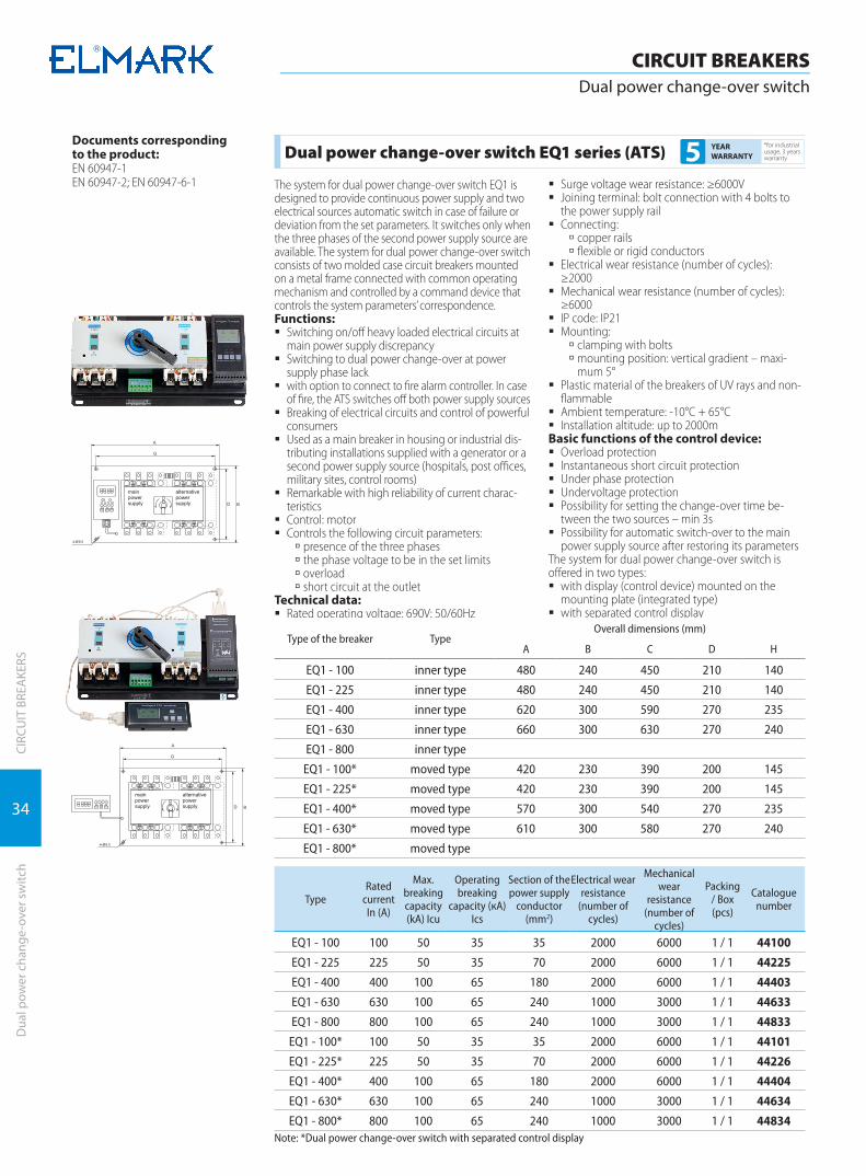
Dual power change-over switch EQ1 series (ATS) *for industrial usage, 3 years warranty5 YEAR
WARRANTY
The system for dual power change-over switch EQ1 is designed to provide continuous power supply and two electrical sources automatic switch in case of failure or deviation from the set parameters. It switches only when the three phases of the second power supply source are available. The system for dual power change-over switch consists of two molded case circuit breakers mounted on a metal frame connected with common operating mechanism and controlled by a command device that controls the system parameters’ correspondence.Functions:
� Switching on/off heavy loaded electrical circuits at main power supply discrepancy
� Switching to dual power change-over at power supply phase lack
� with option to connect to fire alarm controller. In case of fire, the ATS switches off both power supply sources
� Breaking of electrical circuits and control of powerful consumers
� Used as a main breaker in housing or industrial dis-tributing installations supplied with a generator or a second power supply source (hospitals, post offices, military sites, control rooms)
� Remarkable with high reliability of current charac-teristics
� Control: motor � Controls the following circuit parameters:
à presence of the three phases à the phase voltage to be in the set limits à overload à short circuit at the outlet
Technical data: � Rated operating voltage: 690V; 50/60Hz
� Surge voltage wear resistance: ≥6000V � Joining terminal: bolt connection with 4 bolts to
the power supply rail � Connecting:
à copper rails à flexible or rigid conductors
� Electrical wear resistance (number of cycles): ≥2000
� Mechanical wear resistance (number of cycles): ≥6000
� IP code: IP21 � Mounting:
à clamping with bolts à mounting position: vertical gradient – maxi-mum 5°
� Plastic material of the breakers of UV rays and non-flammable
� Ambient temperature: -10°C + 65°C � Installation altitude: up to 2000m
Basic functions of the control device: � Overload protection � Instantaneous short circuit protection � Under phase protection � Undervoltage protection � Possibility for setting the change-over time be-
tween the two sources – min 3s � Possibility for automatic switch-over to the main
power supply source after restoring its parametersThe system for dual power change-over switch is offered in two types:
� with display (control device) mounted on the mounting plate (integrated type)
� with separated control display
Documents correspondingto the product:EN 60947-1EN 60947-2; EN 60947-6-1
Type of the breaker TypeOverall dimensions (mm)
A B C D H
EQ1 - 100 inner type 480 240 450 210 140
EQ1 - 225 inner type 480 240 450 210 140
EQ1 - 400 inner type 620 300 590 270 235
EQ1 - 630 inner type 660 300 630 270 240
EQ1 - 800 inner type
EQ1 - 100* moved type 420 230 390 200 145
EQ1 - 225* moved type 420 230 390 200 145
EQ1 - 400* moved type 570 300 540 270 235
EQ1 - 630* moved type 610 300 580 270 240
EQ1 - 800* moved type
TypeRated
current In (A)
Max. breaking capacity (kA) Icu
Operating breaking
capacity (кА)Ics
Section of the power supply
conductor (mm2)
Electrical wear resistance
(number of cycles)
Mechanical wear
resistance (number of
cycles)
Packing / Box (pcs)
Catalogue number
EQ1 - 100 100 50 35 35 2000 6000 1 / 1 44100
EQ1 - 225 225 50 35 70 2000 6000 1 / 1 44225
EQ1 - 400 400 100 65 180 2000 6000 1 / 1 44403
EQ1 - 630 630 100 65 240 1000 3000 1 / 1 44633
EQ1 - 800 800 100 65 240 1000 3000 1 / 1 44833
EQ1 - 100* 100 50 35 35 2000 6000 1 / 1 44101
EQ1 - 225* 225 50 35 70 2000 6000 1 / 1 44226
EQ1 - 400* 400 100 65 180 2000 6000 1 / 1 44404
EQ1 - 630* 630 100 65 240 1000 3000 1 / 1 44634
EQ1 - 800* 800 100 65 240 1000 3000 1 / 1 44834Note: *Dual power change-over switch with separated control display
35
CIRC
UIT
BRE
AKE
RSM
ould
ed c
ase
circ
uit b
reak
ers
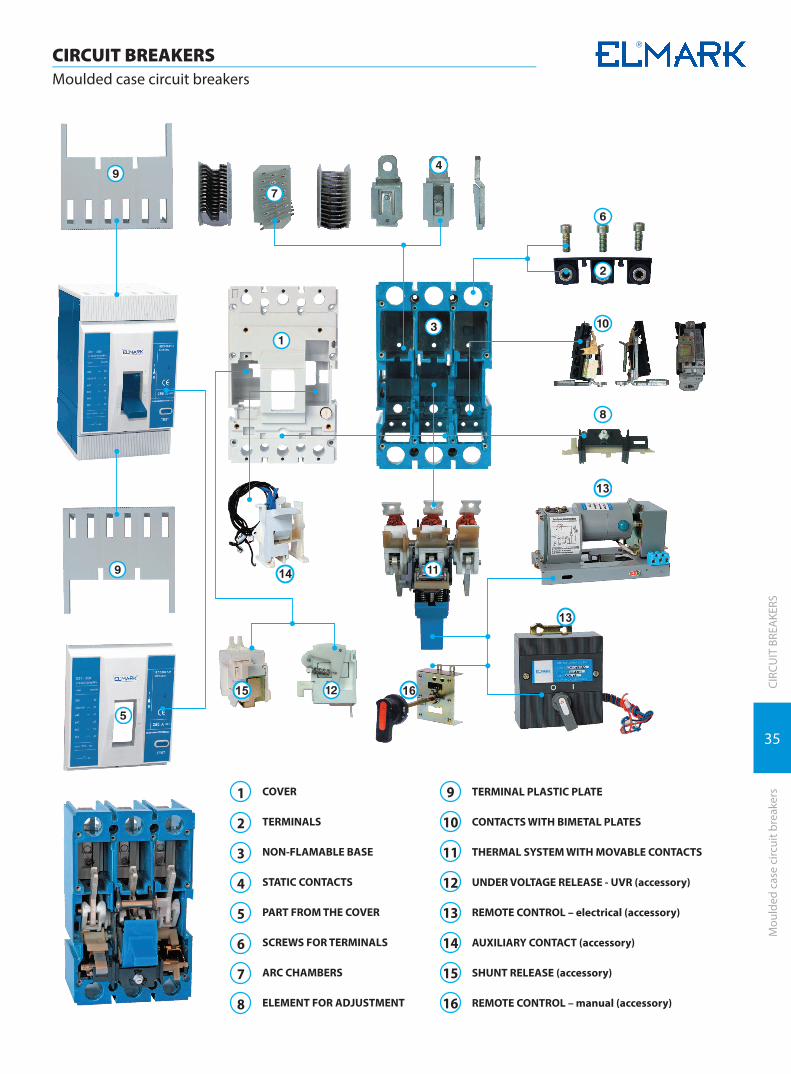
CIRCUIT BREAKERSMoulded case circuit breakers
COVER
TERMINALS
NON-FLAMABLE BASE
STATIC CONTACTS
PART FROM THE COVER
SCREWS FOR TERMINALS
ARC CHAMBERS
ELEMENT FOR ADJUSTMENT
1
2
3
4
5
6
7
8
TERMINAL PLASTIC PLATE
CONTACTS WITH BIMETAL PLATES
THERMAL SYSTEM WITH MOVABLE CONTACTS
UNDER VOLTAGE RELEASE - UVR (accessory)
REMOTE CONTROL – electrical (accessory)
AUXILIARY CONTACT (accessory)
SHUNT RELEASE (accessory)
REMOTE CONTROL – manual (accessory)
9
10
11
12
13
14
15
16
13
13
14
15 16

36
CIRC
UIT
BRE
AKE
RS
CIRCUIT BREAKERSMoulded case circuit breakers
Mou
lded
cas
e ci
rcui
t bre
aker
s
Documents correspondingto the product:Standard EN 60947-1EN 60947-2
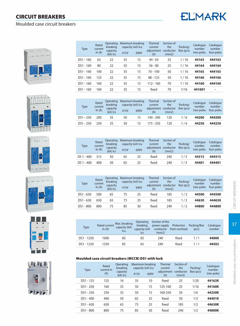
Moulded case circuit breakers (MCCB) DS1 series from 40...1250A
*for industrial usage, 3 years warranty7 YEAR
WARRANTY
Functions: � switching on/off heavy loaded electrical circuits � breaking of electrical circuits and control of power-
ful consumers � can be used as a main breaker in housing or indus-
trial distributing installations � endures high currents of short circuit in the pro-
tected circuit � remarkable with high reliability of current charac-
teristics � control: manual � possibility for auxiliary devices mounting for
automation
Technical data: � Rated operating voltage: 415/690V; 50/60Hz � Isolating voltage: 2000V � Surge voltage wear resistance: ≥8000V � Joining terminal: flat (tunnel) screw terminal for the
breakers up to 160A and a bolt connection for the breakers from 250A to 1600A
� Connecting: à rigid or flexible conductors à front conductors joining à possibility for mounting to lengthening terminal
� Plastic elements à not keeping the burning material nylon PA66 à box permitivity strength: >16MV/m
� Abnormal heating wear resistance and fire of the outer parts: 960°C
� Static contacts – alloy: pure copper T2Y2 à contact head: silver graphite CAg(5) à thickness: depends on the current
� Tightening moment: 1.33Nm � Electrical wear resistance (number of cy-
cles):≥10000 � Mechanical wear resistance (number of cy-
cles):≥20000 � IP code: IP>20 � Mounting:
à joining with bolts à mounting position: vertical
� Plastic material of UV rays and non-flammable � Test button � Ambient temperature: -20°÷65ºС
TypeOverall dimensions (mm) Installation dimensions (mm)
W H D H1 D1 A B W1 H2 Ø d Ø e
DS1-125/3P 76.2 120 70 90 25 100 50 4
DS1-160/3P 90 120 70 93 30 100 60 5
DS1-250/3P 105 170 104 238 143.5 35 139 70 210 6 8.5
DS1-400/3P 140 257 104 316 144 44 214 87.5 285 6 11
DS1-630/3P 210 275 104 310 172 70 230 140 280 6 11
DS1-800/3P 210 275 104 347 172 70 230 140 307 6 16
DS1-1600/3P 210 410 140 410 210 70 300 140 350 10 12
DS1-125/4P 110 120 70 90 25 100 50 4
DS1-160/4P 120 120 70 93 30 100 60 5
DS1-250/4P 140 170 104 238 143.5 35 139 70 210 6 8.5
DS1-400/4P 184 257 104 316 144 44 214 87.5 285 6 11
DS1-630/4P 280 275 104 310 172 70 230 140 280 6 11
DS1-800/4P 280 275 104 347 172 70 230 140 307 6 16
DS1-1600/4P 280 410 140 410 210 70 300 140 350 10 12
TypeRated
current In (A)
Operating breaking capacity (kA) Ics
Maximum breaking capacity (кА) Icu
Thermal current
adjustment (A)
Section of the
conductor(mm2)
Packing/Box (pcs)
Catalogue number
tree-poles
Catalogue number
four-poles415V 690V
DS1-125 40 16 35 10 fixed 16 1 / 20 44040 444040
DS1-125 50 16 35 10 fixed 16 1 / 20 44050 444050
DS1-125 63 16 35 10 fixed 25 1 / 20 44063 444063
DS1-125 80 16 35 10 fixed 25 1 / 20 44080 444080
DS1-125 100 16 35 10 fixed 35 1 / 20 44090 444090
DS1-125 125 16 35 10 fixed 50 1 / 20 44125 444125
37
CIRC
UIT
BRE
AKE
RSM
ould
ed c
ase
circ
uit b
reak
ers
CIRCUIT BREAKERSMoulded case circuit breakers
TypeRated
current In (A)
Operating breaking capacity (kA) Ics
Maximum breaking capacity (кА) Icu
Thermal current
adjustment (A)
Section of the
conductor(mm2)
Packing/Box (pcs)
Catalogue number
tree-poles
Catalogue number
four-poles415V 690V
DS1 - 160 63 22 35 15 44 - 63 25 1 / 16 44163 444163
DS1 - 160 80 22 35 15 56 - 80 25 1 / 16 44164 444164
DS1 - 160 100 22 35 15 70 - 100 50 1 / 16 44165 444165
DS1 - 160 125 22 35 15 88 - 125 50 1 / 16 44166 444166
DS1 - 160 160 22 35 15 112 - 160 70 1 / 16 44160 444160
DS1 - 160 160 22 35 15 fixed 70 1/16 441601 -
TypeRated
current In (A)
Operating breaking capacity (kA) Ics
Maximum breaking capacity (кА) Icu
Thermal current
adjustment (A)
Section of the
conductor(mm2)
Packing/Box (pcs)
Catalogue number
tree-poles
Catalogue number
four-poles415V 690V
DS1 - 250 200 35 50 15 140 - 200 120 1 / 6 44200 444200
DS1 - 250 250 35 50 15 175 - 250 120 1 / 6 44250 444250
TypeRated
current In (A)
Operating breaking capacity (kA) Ics
Maximum breaking capacity (кА) Icu
Thermal current
adjustment (A)
Section of the
conductor(mm2)
Packing/Box (pcs)
Catalogue number
tree-poles
Catalogue number
four-poles415V 690V
DS 1 - 400 315 50 65 25 fixed 240 1 / 3 44315 444315
DS 1 - 400 400 50 65 25 fixed 240 1 / 3 44401 444401
TypeRated
current In (A)
Operating breaking capacity (kA) Ics
Maximum breaking capacity (кА) Icu
Thermal current
adjustment (A)
Section of the
conductor(mm2)
Packing/Box (pcs)
Catalogue number
tree-poles
Catalogue number
four-poles415V 690V
DS1 - 630 500 65 75 25 fixed 185 1 / 2 44500 444500
DS1 - 630 630 65 75 25 fixed 185 1 / 2 44630 444630
DS1 - 800 800 75 85 30 fixed 240 1 / 2 44800 444800
Type Rated current In (A)
Max. breaking capacity (kA)
Icu
Operating breaking
capacity (кА)Ics
Section of the power supply
conductor (mm2)
Protection from overload
Packing/Box (pcs)
Catalogue number
DS1 - 1250 1000 85 65 240 fixed 1 / 1 44000
DS1 - 1250 1250 85 65 240 fixed 1 / 1 44502
Moulded case circuit breakers (MCCB) DS1 with lock
TypeRated
current In (A)
Operating breaking capacity (kA) Ics
Maximum breaking capacity (кА) Icu
Thermal current
adjustment (A)
Section of the
conductor(mm2)
Packing/Box (pcs)
Catalogue number
tree-poles415V 690V
DS1 - 125 125 16 35 10 fixed 25 1/20 44163K
DS1 - 250 160 35 50 15 125-160 25 1/16 44160K
DS1 - 250 250 35 50 15 160-250 50 1/6 44250K
DS1 - 400 400 50 65 25 fixed 50 1/3 44401K
DS1 - 630 630 65 75 25 fixed 185 1/2 44630K
DS1 - 800 800 75 85 30 fixed 240 1/2 44800K
38
CIRC
UIT
BRE
AKE
RS
CIRCUIT BREAKERSMoulded case circuit breakers
Mou
lded
cas
e ci
rcui
t bre
aker
s
Documents correspondingto the product:Standard EN 60947-1EN 60947-2
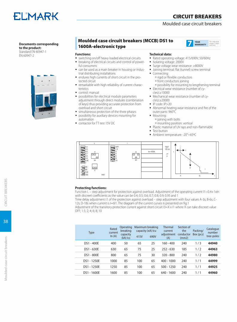
Protecting functions:Function L – step adjustment for protection against overload. Adjustment of the operating current I1=0.4+1xIn with discreet coefficients as the value can be 0.4; 0.5; 0.6; 0.7; 0.8; 0.9; 0.95 and 1Time delay adjustment t1 of the protection against overload – step adjustment with four values A-3s; B-6s; C-12s; D-18s when current is I=6I1. The diagram of the current curves is presented on fig.1Adjustment of the transitory protection current against short circuit I3=X x I1 where X can take discreet value OFF; 1.5; 2; 4; 6; 8; 10
TypeRated
current In (A)
Operating breaking capacity (kA) Ics
Maximum breaking capacity (кА) Icu
Thermal current
adjustment (A)
Section of the
conductor(mm2)
Packing/Box (pcs)
Catalogue number
tree-poles415V 690V
DS1 - 400Е 400 50 65 25 160 - 400 240 1 / 3 44940
DS1 - 630Е 630 65 75 25 252 - 630 185 1 / 2 44963
DS1 - 800Е 800 65 75 30 320 - 800 240 1 / 2 44980
DS1 - 1250Е 1000 85 100 65 400 - 1000 240 1 / 1 44999
DS1 - 1250Е 1250 85 100 65 500 - 1250 240 1 / 1 44925
DS1 - 1600Е 1600 85 100 65 640 - 1600 240 1 / 1 44960
Moulded case circuit breakers (MCCB) DS1 to 1600A-electronic type
*for industrial usage, 3 years warranty7 YEAR
WARRANTY
Functions: � switching on/off heavy loaded electrical circuits � breaking of electrical circuits and control of power-
ful consumers � can be used as a main breaker in housing or indus-
trial distributing installations � endures high currents of short circuit in the pro-
tected circuit � remarkable with high reliability of current charac-
teristics � control: manual � possibilities for electrical module parameters
adjustment through direct modules (combination of keys) thus providing accurate protection from overload and short circuit
� simultaneous protection of the three phases � possibility for auxiliary devices mounting for
automation � contactor for TT test 15V DC
Technical data: � Rated operating voltage: 415/690V; 50/60Hz � Isolating voltage: 2000V � Surge voltage wear resistance: ≥8000V � Joining terminal: flat (tunnel) screw terminal � Connecting:
à rigid or flexible conductors à front conductors joining à possibility for mounting to lengthening terminal
� Electrical wear resistance (number of cy-cles):≥10000
� Mechanical wear resistance (number of cy-cles):≥20000
� IP code: IP>20 � Abnormal heating wear resistance and fire of the
outer parts: 960°C � Mounting:
à joining with bolts à mounting position: vertical
� Plastic material of UV rays and non-flammable � Test button � Ambient temperature: -20°÷65ºС

39
CIRC
UIT
BRE
AKE
RSM
ould
ed c
ase
circ
uit b
reak
ers
CIRCUIT BREAKERSMoulded case circuit breakers
Documents correspondingto the product:Standard EN 60947-1EN 60947-2
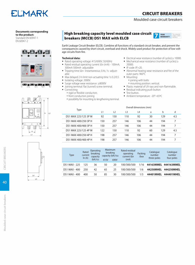
High breaking capacity level moulded case circuit breakers (MCCB) DS1 MAX from 63A... 800A
*for industrial usage, 3 years warranty7 YEAR
WARRANTY
Functions: � high breaking capacity level � switching on/off heavy loaded electrical circuits � breaking of electrical circuits and control of power-
ful consumers � can be used as a main breaker in housing or indus-
trial distributing installations � endures high currents of short circuit in the pro-
tected circuit � remarkable with high reliability of current charac-
teristics control: manual � possibility for auxiliary devices mounting for
automation
Technical data: � Rated operating voltage: 415/690V; 50/60Hz � Isolating voltage: 2000V � Surge voltage wear resistance: ≥8000V � Connecting:
à rigid or flexible conductors à front conductors joining à possibility for mounting to lengthening terminal
� Plastic elements à not keeping the burning material nylon PA66 à box permitivity strength: >16MV/m
� Abnormal heating wear resistance and fire of the outer parts: 960°C
� Static contacts – alloy: pure copper T2Y2 à аcontact head: silver graphite CAg(5) à аthickness: depends on the current
� Tightening moment: 1.33Nm � Electrical wear resistance (number of cycles):
≥10000 � Mechanical wear resistance (number of cycles):
≥20000 � IP code: IP>20 � Mounting:
à joining with bolts à mounting position: vertical
� Plastic material of UV rays and non-flammable � Test button � Ambient temperature: -20°/65°C.
TypeOverall dimensions (mm)
L1 L2 L3 L4 a b d
DS1 MAX 125/63 3P M 92 150 110 92 30 129 4.5 DS1 MAX 125/80 3PM 92 150 110 92 30 129 4.5
DS1 MAX 125/100 3P M 92 150 110 92 30 129 4.5 DS1 MAX 125/125 3P M 92 150 110 92 30 129 4.5 DS1 MAX 250/160 3P M 92 165 110 90 35 126 4.5 DS1 MAX 250/200 3P M 107 165 110 90 35 126 4.5 DS1 MAX 250/250 3P H 107 165 110 90 35 126 4.5 DS1 MAX 400/400 3P H 150 257 146 106 44 194 7 DS1 MAX 630/630 3P H 182 270 155 116 116 200 7 DS1 MAX 800/800 3P H 210 28 155 116 70 243 7 DS1 MAX 125/63 4P M 122 150 110 92 60 129 4.5 DS1 MAX 125/80 4PM 122 150 110 92 60 129 4.5 DS1 MAX 125/100 4P M 122 150 110 92 60 129 4.5 DS1 MAX 125/125 4P M 122 150 110 92 60 129 4.5 DS1 MAX 250/160 4P M 142 165 110 90 70 126 4.5 DS1 MAX 250/200 4P M 142 165 110 90 70 126 4.5 DS1 MAX 250/250 4P H 142 165 110 90 70 126 4.5 DS1 MAX 400/400 4P H 198 257 146 106 44 194 7 DS1 MAX 630/630 4P H 240 270 155 116 116 200 7 DS1 MAX 800/800 4P H 280 280 155 116 70 243 7
TypeRated
current ln (A)
Operating breaking capacity (kA) lcs
Maximum breaking capacity (kA) lcu
Thermal current
adjusment (A)
Packing/box
Catalogue number
three-poles
Catalogue number
four-poles415V 690V
DS1 MAX - 125 63 36 50 20 50,4-63 1/16 44163MM 444163MMDS1 MAX - 125 80 36 50 20 64-80 1/16 44164MM 444164MMDS1 MAX - 125 100 36 50 20 80-100 1/16 44165MM 444165MMDS1 MAX - 125 125 36 50 20 100-125 1/16 44166MM 444166MMDS1 MAX - 250 160 36 50 20 128-160 1/6 44160MM 444160MMDS1 MAX - 250 200 36 50 20 160-200 1/6 44200MM 444200MMDS1 MAX - 250 250 42 65 25 200-250 1/6 44250MH 444250MHDS1 MAX - 400 400 50 85 30 320-400 1/3 44401MH 444401MHDS1 MAX - 630 630 50 85 30 504-630 1/2 44630MH 444630MHDS1 MAX - 800 800 65 100 50 640-800 1/2 44800MH 444800MH
40
CIRC
UIT
BRE
AKE
RS
CIRCUIT BREAKERSMoulded case circuit breakers
Mou
lded
cas
e ci
rcui
t bre
aker
s
Documents correspondingto the product:Standard EN 60947-1EN 60947-2
TypeOverall dimensions (mm)
L1 L2 L3 L4 a b d
DS1 MAX 225/125 3P M 92 150 110 92 30 129 4.5
DS1 MAX 400/250 3P H 150 257 146 106 44 194 7
DS1 MAX 400/400 3P H 150 257 146 106 44 194 7
DS1 MAX 225/125 4P M 122 150 110 92 60 129 4.5
DS1 MAX 400/250 4P H 198 257 146 106 44 194 7
DS1 MAX 400/400 4P H 198 257 146 106 44 194 7
TypeRated
current ln (A)
Operating breaking capacity (kA) lcs
Maximum breaking
capacity (kA) lcu
Rated residual operating
current IΔn (mA)
Packing /box
Catalogue number
three-poles
Catalogue number
four-poles415V 690V
DS1 MAX - 225 125 36 50 20 100/300/500 1/16 44163MMEL 444163MMEL
DS1 MAX - 400 250 42 65 25 100/300/500 1/6 44250MHEL 444250MHEL
DS1 MAX - 400 400 50 85 30 100/300/500 1/3 44401MHEL 444401MHEL
High breaking capacity level moulded case circuit breakers (MCCB) DS1 MAX with ELCB
*for industrial usage, 3 years warranty7 YEAR
WARRANTY
Earth Leakage Circuit Breaker (ELCB). Combine all functions of a standard circuit breaker, and prevent the consequences caused by short circuit, overload and shock. Widely used product for protection of low volt-age circuits from fire.
Technical data: � Rated operating voltage: 415/690V; 50/60Hz � Rated residual operating current IΔn (mA) - 100mA;
300mA 500mA- adjustable � Tripping time IΔn- instantaneous; 0.4s; 1s -adjust-
able � Max delayed 2 ln limit non-actuating time 1s 0.2/0.5 � Isolating voltage: 2000V. � Surge voltage wear resistance: ≥8000V � Joining terminal: flat (tunnel) screw terminal. � Connecting:
à rigid or flexible conductors à front conductors joining à possibility for mounting to lengthening terminal.
� Electrical wear resistance (number of cycles):≥ 10000. � Mechanical wear resistance (number of cycles):≥
20000. � IP code: IP>20. � Abnormal heating wear resistance and fire of the
outer parts: 960°C � Mounting:
à joining with bolts à mounting position: vertical.
� Plastic material of UV rays and non-flammable. � Residual indicating push button � Test button. � Ambient temperature: -20°÷65ºС

41
CIRC
UIT
BRE
AKE
RSM
ould
ed c
ase
circ
uit b
reak
ers
CIRCUIT BREAKERSMoulded case circuit breakers
Tripping characteristic: Ir1(A) Over-load long time delay tripping current
Ir1 adjustment, according to the different rated current of MCCB.
t1(s) Long time delay tripping time t1 adjustment.
Ir2(XIr1) Short circuit short time delay tripping time Ir2 adjustment.
t2(s) Short time delay tripping time t2 adjustment.
Ir3(XIr1) Short circuit instantaneous tripping current Ir3 adjustment.
Ir0(XIr1) Pre-alarm tripping current Ir0 adjustment.
Documents correspondingto the product:Standard EN 60947-1EN 60947-2
TypeRated
current ln (A)
Operating breaking capacity (kA) lcs
Maximum breaking capacity (kA) lcu
Thermal current
adjusment (A)
Packing/box
Catalogue number
three-poles
Catalogue number
four-poles415V 690V
DS1 MAX - 400E 400 50 85 30 200-400 1/3 44940MH 444940MH
DS1 MAX - 630E 630 50 85 30 400-630 1/2 44963MH 444963MH
DS1 MAX - 800E 800 65 100 50 630-800 1/2 44980MH 444980MH
High breaking capacity level moulded case circuit breakers (MCCB) DS1 MAX to 800A-electronic type
*for industrial usage, 3 years warranty7 YEAR
WARRANTY
Functions: � high breaking capacity level � switching on/off heavy loaded electrical circuits � breaking of electrical circuits and control of power-
ful consumers � can be used as a main breaker in housing or indus-
trial distributing installations � endures high currents of short circuit in the pro-
tected circuit � remarkable with high reliability of current charac-
teristics � control: manual � possibilities for electrical module parameters
adjustment through direct modules (combination of keys) thus providing accurate protection from overload and short circuit
� simultaneous protection of the three phases � possibility for auxiliary devices mounting for
automation � contactor for TT test 15V DC
Technical data: � Rated operating voltage: 415/690V; 50/60Hz � Isolating voltage: 2000V � Surge voltage wear resistance: ≥8000V � Joining terminal: flat (tunnel) screw terminal � Connecting:
à rigid or flexible conductors à front conductors joining à possibility for mounting to lengthening terminal
� Electrical wear resistance (number of cycles):≥ 10000
� Mechanical wear resistance (number of cycles):≥ 20000
� IP code: IP>20 � Abnormal heating wear resistance and fire of the
outer parts: 960°C � Mounting:
à joining with bolts à mounting position: vertical
� Plastic material of UV rays and non-flammable � Test button � Ambient temperature: -20°÷65ºС
DS1 MAX - 400E
DS1 MAX - 630E
DS1 MAX - 800E
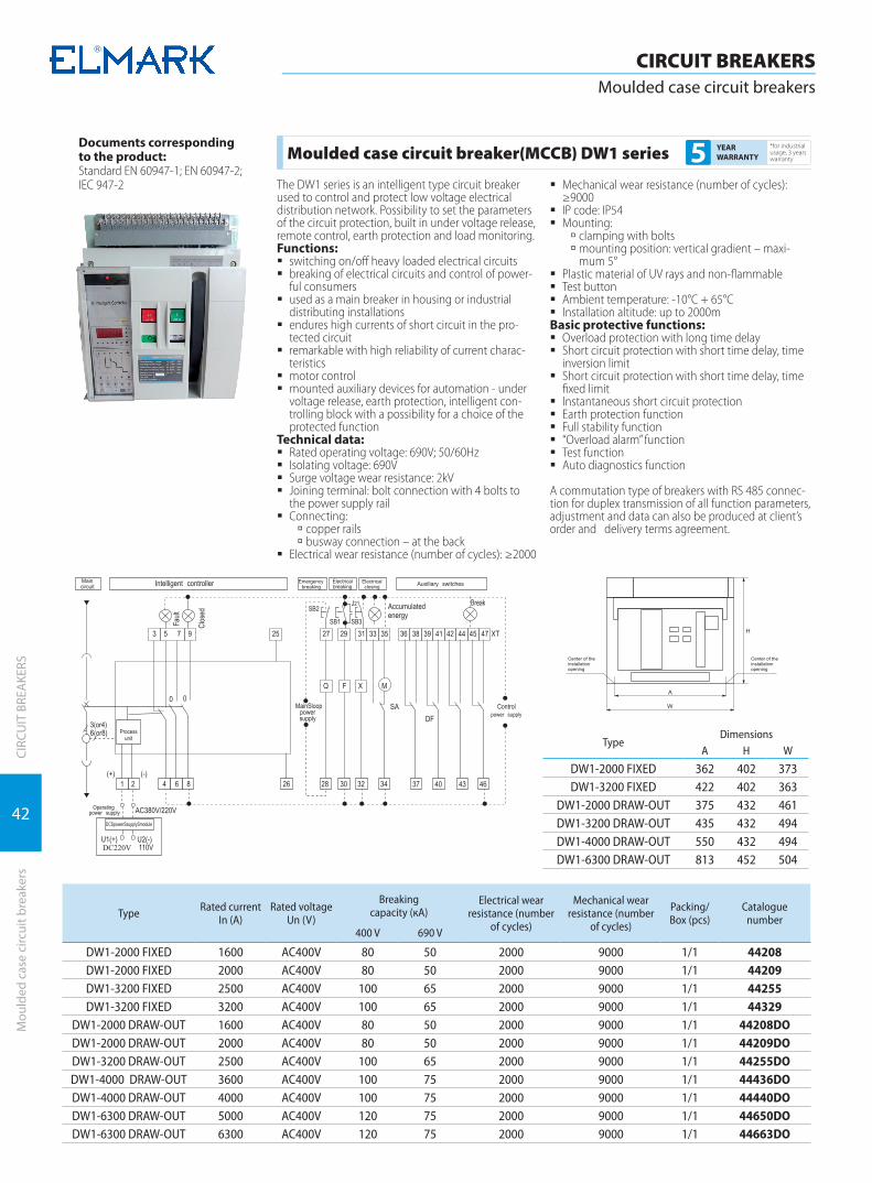
42
CIRC
UIT
BRE
AKE
RS
CIRCUIT BREAKERSMoulded case circuit breakers
Mou
lded
cas
e ci
rcui
t bre
aker
s
Documents correspondingto the product:Standard EN 60947-1; EN 60947-2; IEC 947-2
TypeDimensions
A H W
DW1-2000 FIXED 362 402 373DW1-3200 FIXED 422 402 363
DW1-2000 DRAW-OUT 375 432 461DW1-3200 DRAW-OUT 435 432 494DW1-4000 DRAW-OUT 550 432 494DW1-6300 DRAW-OUT 813 452 504
Type Rated current In (A)
Rated voltage Un (V)
Breakingcapacity (кА)
Electrical wear resistance (number
of cycles)
Mechanical wear resistance (number
of cycles)
Packing/Box (pcs)
Catalogue number
400 V 690 V
DW1-2000 FIXED 1600 AC400V 80 50 2000 9000 1/1 44208DW1-2000 FIXED 2000 AC400V 80 50 2000 9000 1/1 44209DW1-3200 FIXED 2500 AC400V 100 65 2000 9000 1/1 44255DW1-3200 FIXED 3200 AC400V 100 65 2000 9000 1/1 44329
DW1-2000 DRAW-OUT 1600 AC400V 80 50 2000 9000 1/1 44208DODW1-2000 DRAW-OUT 2000 AC400V 80 50 2000 9000 1/1 44209DODW1-3200 DRAW-OUT 2500 AC400V 100 65 2000 9000 1/1 44255DODW1-4000 DRAW-OUT 3600 AC400V 100 75 2000 9000 1/1 44436DODW1-4000 DRAW-OUT 4000 AC400V 100 75 2000 9000 1/1 44440DODW1-6300 DRAW-OUT 5000 AC400V 120 75 2000 9000 1/1 44650DODW1-6300 DRAW-OUT 6300 AC400V 120 75 2000 9000 1/1 44663DO
Moulded case circuit breaker(MCCB) DW1 series*for industrial usage, 3 years warranty5 YEAR
WARRANTY
The DW1 series is an intelligent type circuit breaker used to control and protect low voltage electrical distribution network. Possibility to set the parameters of the circuit protection, built in under voltage release, remote control, earth protection and load monitoring.Functions:
� switching on/off heavy loaded electrical circuits � breaking of electrical circuits and control of power-
ful consumers � used as a main breaker in housing or industrial
distributing installations � endures high currents of short circuit in the pro-
tected circuit � remarkable with high reliability of current charac-
teristics � motor control � mounted auxiliary devices for automation - under
voltage release, earth protection, intelligent con-trolling block with a possibility for a choice of the protected function
Technical data: � Rated operating voltage: 690V; 50/60Hz � Isolating voltage: 690V � Surge voltage wear resistance: 2kV � Joining terminal: bolt connection with 4 bolts to
the power supply rail � Connecting:
à copper rails à busway connection – at the back
� Electrical wear resistance (number of cycles): ≥2000
� Mechanical wear resistance (number of cycles): ≥9000
� IP code: IP54 � Mounting:
à clamping with bolts à mounting position: vertical gradient – maxi-mum 5°
� Plastic material of UV rays and non-flammable � Test button � Ambient temperature: -10°C + 65°C � Installation altitude: up to 2000m
Basic protective functions: � Overload protection with long time delay � Short circuit protection with short time delay, time
inversion limit � Short circuit protection with short time delay, time
fixed limit � Instantaneous short circuit protection � Earth protection function � Full stability function � “Overload alarm” function � Test function � Auto diagnostics function
A commutation type of breakers with RS 485 connec-tion for duplex transmission of all function parameters, adjustment and data can also be produced at client’s order and delivery terms agreement.
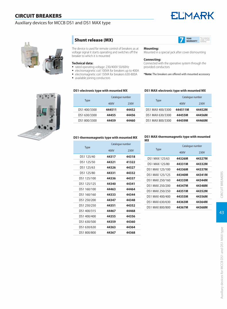
43
CIRC
UIT
BRE
AKE
RS
CIRCUIT BREAKERSAuxiliary devices for MCCB DS1 and DS1 MAX type
Auxi
liary
dev
ices
for M
CCB
DS1
and
DS1
MAX
type
Shunt release (MX)*for industrial usage, 3 years warranty7 YEAR
WARRANTY
The device is used for remote control of breakers as at voltage signal it starts operating and switches off the breaker to which it is mounted
Technical data: � rated operating voltage: 230/400V 50/60Hz � electromagnetic coil 100VA for breakers up to 400A � electromagnetic coil 150VA for breakers 630-800A � available joining conductors
Mounting:Mounted in a special jack after cover dismounting
Connecting:Connected with the operative system through the provided conductors
*Note: The breakers are offered with mounted accessory
DS1-electronic type with mounted MX
TypeCatalogue number
400V 230V
DS1 400/3300 444511 44452
DS1 630/3300 44455 44456
DS1 800/3300 44459 44460
DS1-thermomagnetic type with mounted MX
TypeCatalogue number
400V 230V
DS1 125/40 44317 44318
DS1 125/50 44321 41322
DS1 125/63 44326 44327
DS1 125/80 44331 44332
DS1 125/100 44336 44337
DS1 125/125 44340 44341
DS1 160/100 44463 44464
DS1 160/160 44333 44344
DS1 250/200 44347 44348
DS1 250/250 44351 44352
DS1 400/315 44467 44468
DS1 400/400 44355 44356
DS1 630/500 44359 44360
DS1 630/630 44363 44364
DS1 800/800 44367 44368
DS1 MAX-electronic type with mounted MX
TypeCatalogue number
400V 230V
DS1 MAX 400/3300 444511M 44452M
DS1 MAX 630/3300 44455M 44456M
DS1 MAX 800/3300 44459M 44460M
DS1 MAX-thermomagnetic type with mounted MX
TypeCatalogue number
400V 230V
DS1 MAX 125/63 44326M 44327M
DS1 MAX 125/80 44331M 44332M
DS1 MAX 125/100 44336M 44337M
DS1 MAX 125/125 44340M 44341M
DS1 MAX 250/160 44333M 44344M
DS1 MAX 250/200 44347M 44348M
DS1 MAX 250/250 44351M 44352M
DS1 MAX 400/400 44355M 44356M
DS1 MAX 630/630 44363M 44364M
DS1 MAX 800/800 44367M 44368M
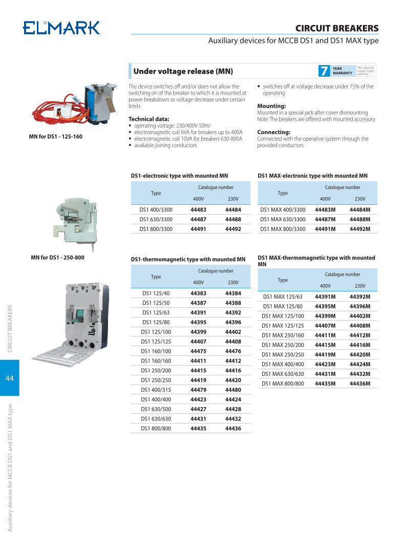
44
CIRC
UIT
BRE
AKE
RS
CIRCUIT BREAKERSAuxiliary devices for MCCB DS1 and DS1 MAX type
Auxi
liary
dev
ices
for M
CCB
DS1
and
DS1
MAX
type
MN for DS1 - 125-160
DS1-electronic type with mounted MN
TypeCatalogue number
400V 230V
DS1 400/3300 44483 44484
DS1 630/3300 44487 44488
DS1 800/3300 44491 44492
DS1-thermomagnetic type with mounted MN
TypeCatalogue number
400V 230V
DS1 125/40 44383 44384
DS1 125/50 44387 44388
DS1 125/63 44391 44392
DS1 125/80 44395 44396
DS1 125/100 44399 44402
DS1 125/125 44407 44408
DS1 160/100 44475 44476
DS1 160/160 44411 44412
DS1 250/200 44415 44416
DS1 250/250 44419 44420
DS1 400/315 44479 44480
DS1 400/400 44423 44424
DS1 630/500 44427 44428
DS1 630/630 44431 44432
DS1 800/800 44435 44436
DS1 MAX-electronic type with mounted MN
TypeCatalogue number
400V 230V
DS1 MAX 400/3300 44483M 44484M
DS1 MAX 630/3300 44487M 44488M
DS1 MAX 800/3300 44491M 44492M
DS1 MAX-thermomagnetic type with mounted MN
TypeCatalogue number
400V 230V
DS1 MAX 125/63 44391M 44392M
DS1 MAX 125/80 44395M 44396M
DS1 MAX 125/100 44399M 44402M
DS1 MAX 125/125 44407M 44408M
DS1 MAX 250/160 44411M 44412M
DS1 MAX 250/200 44415M 44416M
DS1 MAX 250/250 44419M 44420M
DS1 MAX 400/400 44423M 44424M
DS1 MAX 630/630 44431M 44432M
DS1 MAX 800/800 44435M 44436M
MN for DS1 - 250-800
Under voltage release (MN)*for industrial usage, 3 years warranty7 YEAR
WARRANTY
The device switches off and/or does not allow the switching on of the breaker to which it is mounted at power breakdown or voltage decrease under certain limits
Technical data: � operating voltage: 230/400V 50Hz � electromagnetic coil 6VA for breakers up to 400A � electromagnetic coil 10VA for breakers 630-800A � available joining conductors
� switches off at voltage decrease under 75% of the operating
Mounting:Mounted in a special jack after cover dismounting Note: The breakers are offered with mounted accessory
Connecting:Connected with the operative system through the provided conductors

45
CIRC
UIT
BRE
AKE
RS
CIRCUIT BREAKERSAuxiliary devices for MCCB DS1 and DS1 MAX type
Auxi
liary
dev
ices
for M
CCB
DS1
and
DS1
MAX
type
Documents correspondingto the product:Standard EN 60947-1EN 60947-2
DS1-thermomagnetic type with mounted OF
Type Catalogue number
DS1 125/40 44301
DS1 125/50 44302
DS1 125/63 44303
DS1 125/80 44304
DS1 125/100 44305
DS1 125/125 44306
DS1 160/160 44307
DS1 250/200 44308
DS1 250/250 44309
DS1 400/400 44310
DS1 630/500 44311
DS1 630/630 44312
DS1 800/800 44313
DS1 MAX-thermomagnetic type with mounted OF
Type Catalogue number
DS1 MAX 125/63 44303M
DS1 MAX 125/80 44304M
DS1 MAX 125/100 44305M
DS1 MAX 125/125 44306M
DS1 MAX 250/160 44307M
DS1 MAX 250/200 44308M
DS1 MAX 250/250 44309M
DS1 MAX 400/400 44310M
DS1 MAX 630/630 44312M
DS1 MAX 800/800 44313M
Auxiliary contact (OF)*for industrial usage, 3 years warranty7 YEAR
WARRANTY
According to the way of mounting the auxiliary devices can be divided into two groups:
� internal devices – accessories for whose mounting it is necessary to dismount the cover of the breakers and fix them in specially designed jacks
� external devices – they are mounted right on the top cover of the breaker
INTERNAL DEVICES
Auxiliary contact (OF)The device changes its condition conformably to the breaker’s condition; it has a NO and a NC contactor.
Technical data: � for breakers up to 160A operating current through
the auxiliary contact: 3A � for breakers from 250 to 800A operating current
through the auxiliary contact: 6A � available joining conductors � labeling of the cables
Mounting:Mounted in a special jack after cover dismountingNote: The breakers are offered with mounted accessoryConnecting:Connected with the operative system through the provided conductors

46
CIRC
UIT
BRE
AKE
RS
CIRCUIT BREAKERSAuxiliary devices for MCCB DS1 and DS1 MAX type
Auxi
liary
dev
ices
for M
CCB
DS1
and
DS1
MAX
type
DS1 -electronic type with mounted MX+OF
TypeCatalogue number
400V 230V
DS1 400/3300 44453 44454
DS1 630/3300 44457 44458
DS1 800/3300 44461 44462
DS1-thermomagnetic type with mounted MX+OF
TypeCatalogue number
400V 230V
DS1 125/40 44319 44320
DS1 125/50 44323 41324
DS1 125/63 44328 44330
DS1 125/80 44334 44335
DS1 125/100 44338 44339
DS1 125/125 44342 44343
DS1 160/100 44465 44466
DS1 160/160 44345 44346
DS1 250/200 44349 44350
DS1 250/250 44353 44354
DS1 400/315 44469 44470
DS1 400/400 44357 44358
DS1 630/500 44361 44362
DS1 630/630 44365 44366
DS1 800/800 44369 44370
DS1 MAX-thermomagnetic type with mounted MN+OF
TypeCatalogue number
400V 230V
DS1 MAX 125/63 44393M 44394M
DS1 MAX 125/80 44397M 44398M
DS1 MAX 125/100 44405M 44406M
DS1 MAX 125/125 44409M 44410M
DS1 MAX 250/160 44413M 44414M
DS1 MAX 250/200 44417M 44418M
DS1 MAX 250/250 44421M 44422M
DS1 MAX 400/400 44425M 44426M
DS1 MAX 630/630 44433M 44434M
DS1 MAX 800/800 44437M 44438M
DS1 MAX-electronic type with mounted MN+OF
TypeCatalogue number
400V 230V
DS1 MAX 400/3300 44485М 44486M
DS1 MAX 630/3300 44489M 44490M
DS1 MAX 800/3300 44493M 44494M
DS1 MAX-electronic type with mounted MX+OF
TypeCatalogue number
400V 230V
DS1 MAX 400/3300 44453M 44454M
DS1 MAX 630/3300 44457M 44458M
DS1 MAX 800/3300 44461M 44462M
DS1 MAX- thermomagnetic type with mounted MX+OF
TypeCatalogue number
400V 230V
DS1 MAX 125/63 44328M 44330M
DS1 MAX 125/80 44334M 44335M
DS1 MAX 125/100 44338M 44339M
DS1 MAX 125/125 44342M 44343M
DS1 MAX 250/160 44345M 44346M
DS1 MAX 250/200 44349M 44350M
DS1 MAX 250/250 44353M 44354M
DS1 MAX 400/400 44357M 44358M
DS1 MAX 630/630 44365M 44366M
DS1 MAX 800/800 44369M 44370M
DS1-thermomagnetic type with mounted MN+OF
TypeCatalogue number
400V 230V
DS1 125/40 44385 44386
DS1 125/50 44389 44390
DS1 125/63 44393 44394
DS1 125/80 44397 44398
DS1 125/100 44405 44406
DS1 125/125 44409 44410
DS1 160/100 44477 44478
DS1 160/160 44413 44414
DS1 250/200 44417 44418
DS1 250/250 44421 44422
DS1 400/315 44481 44482
DS1 400/400 44425 44426
DS1 630/500 44429 44430
DS1 630/630 44433 44434
DS1 800/800 44437 44438
DS1-electronic type with mounted MN+OF
TypeCatalogue number
400V 230V
DS1 400/3300 44485 44486
DS1 630/3300 44489 44490
DS1 800/3300 44493 44494
MCCB with auxiliary devices mounted (MX+OF) and (MN+OF)
*for industrial usage, 3 years warranty7 YEARS
GUARANTEE

47
CIRC
UIT
BRE
AKE
RS
CIRCUIT BREAKERSAuxiliary devices for MCCB DS1 and DS1 MAX type
Auxi
liary
dev
ices
for M
CCB
DS1
and
DS1
MAX
type
Terminal plates for MCCB - DS1 and DS1 MAX type*for industrial usage, 3 years warranty7 YEAR
WARRANTY
Straight copper electro-tinned extensions enabling cable connection outside the switch terminals and provid-ing excellent contact with the switch terminal base. Terminal extensions with different cross section are avail-able depending on the switch rated power.
Mounting:Extensions are directly bolt mounted to the switch terminal base.
Terminal plates for MCCB - DS1
Type Rated current (А) Catalogue number 3pcs/set
Catalogue number 4pcs/set
TP 125 125 31125 314125
TP 160 160 31160 314160
TP 250 250 31250 314250
TP 400 400 31400 314400
TP 630 630 31630 314630
TP 800 800 31850 314850
TP 1250 1250 311250 -
Terminal plates for MCCB - DS1 MAX
Type Rated current (А) Catalogue number 3pcs/set
Catalogue number 4pcs/set
TP 125 MAX 125 31125M -
TP 250 MAX 250 31250M -
TP 400 MAX 400 31400M 314400M
TP 630 MAX 630 31630M 314630M
TP 800 MAX 800 31850M 314850M

48
CIRC
UIT
BRE
AKE
RS
CIRCUIT BREAKERSAuxiliary devices for MCCB DS1 and DS1 MAX type
Auxi
liary
dev
ices
for M
CCB
DS1
and
DS1
MAX
type
Remote control (manual)*for industrial usage, 3 years warranty5 YEAR
WARRANTY
Description:The device switches off/on the breaker to which manual operative rotary mechanism is mounted
� two operating positions of the executive mecha-nism fixed at 90°C
Mounting:The base is mounted with bolts right on the cover (scheme 1 mounting), and the handle is mounted at the door of the distribution box, using an extension axis it is joined to the base
Remote control for MCCB, DS1
Type of the breakerDimensions (mm) Packing/
Box (pcs) Catalogue numberA B C Dmin Dmax
DS1 125A 25 50 50 65 115 1 44967DS1 160A 30 50 50 65 115 1 44968DS1 250A 35 70 70 80 130 1 44969DS1 400A 45 107 107 85 105 1 44970DS1 630A 70 119 119 110 110 1 44971DS1 800A 70 119 119 110 110 1 44972
Remote control for MCCB, DS1 MAX
Type of the breakerDimensions (mm) Packing/
Box (pcs) Catalogue numberA B C Dmin Dmax
DS1 MAX 63A 25 50 50 65 115 1 44966MDS1 MAX 125A 25 50 50 65 115 1 44967MDS1 MAX 250A 35 70 70 80 130 1 44969MDS1 MAX 400A 45 107 107 85 105 1 44970M
DS1 MAX 630/800A 70 119 119 110 110 1 44972M

49
CIRC
UIT
BRE
AKE
RS
CIRCUIT BREAKERSAuxiliary devices for MCCB DS1 and DS1 MAX type
Auxi
liary
dev
ices
for M
CCB
DS1
and
DS1
MAX
type
DS1 - 125-160
DS1 - 250-800
Remote control (electrical)*for industrial usage, 3 years warranty5 YEARS
GUARANTEE
Description:The device switches off/on the breaker to which manual operative rotary mechanism is mounted
� two operating positions of the executive mecha-nism fixed at 90°C
Mounting:The base is mounted with bolts right on the cover (scheme 1 mounting), and the handle is mounted at the door of the distribution box, using an extension axis it is joined to the base
Electrical remote control for MCCB DS1
Type of the breakerDimensions (mm) Packing/
Box (pcs)
Catalogue numberOperating voltage (V)
A A1 B B1 H 230V 400V
DS1 125 103.5 110 30 90 92 1 44912 44907DS1 160 103.5 110 35 90 92 1 44913 44908DS1 250 139 - 132 - 105 1 44914 44909DS1 400 226 - 132 - 132 1 44915 44910DS1 630 226 - 132 - 132 1 44916 44911DS1 800 226 - 132 - 132 1 44916 44911
Electrical remote control for MCCB DS1 MAX
Type of the breakerDimensions (mm) Packing/
Box (pcs)
Catalogue numberOperating voltage (V)
L1 B B H H1 230V 400V
DS1 MAX 63A 116 90 50 77 12,5 1 44917M 44906MDS1 MAX 125A 116 90 50 77 12,5 1 44912M 44907MDS1 MAX 250A 116 90 70 77 15 1 44914M 44909MDS1 MAX 400A 176 130 107 115 27 1 44915M 44910M
DS1 MAX 630/800A 176 130 119 115 31 1 44916M 44911MDS1 MAX - 63-250
INDIRECT
T
INDIRECT PROTECTION DEVICES
PROTECTION DEVICES
Residual current devices | 52
Combined residual current devices | 56
Surge arresters | 59
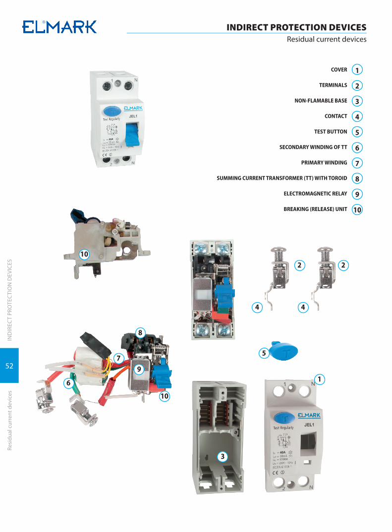
52
INDIRECT PROTECTION DEVICESResidual current devices
IND
IREC
T PR
OTE
CTI
ON
DEV
ICES
Resi
dual
cur
rent
dev
ices
COVER
TERMINALS
NON-FLAMABLE BASE
CONTACT
TEST BUTTON
SECONDARY WINDING OF TT
PRIMARY WINDING
SUMMING CURRENT TRANSFORMER (TT) WITH TOROID
ELECTROMAGNETIC RELAY
BREAKING (RELEASE) UNIT
1
2
3
4
5
6
7
8
9
10
10
10
79
8
6
5
4 4
3
2 2
1

53
INDIRECT PROTECTION DEVICESResidual current devices
IND
IREC
T PR
OTE
CTI
ON
DEV
ICES
Resi
dual
cur
rent
dev
ices
Type AC for AC current
Documents correspondingto the product:EN 61008-1EN 61008-2; EN 60947-1
Residual current devices JEL1*for industrial usage, 3 years warranty7 YEAR
WARRANTY
The residual current device works with no extra pow-er supply to the operating mechanism. It compares the magnitude of the currents through the neutral and phase conductors. The conductors are coiled on toroid and together with the secondary winding form a measurement transformer. The power conductors are coiled in such a way that the magnetic fields generated at electrical current flow through them are mutually neutralized. At failure in the insulation of some of the conductors or at presence of a person under voltage, the system is misbalanced and the magnetic fields can not be neutralized. This residual field generates in the secondary current winding, called current leakage. The device breaks when the value of this current exceeds the limit value of the residual current breaker.
Functions: � switching off heavy-loaded electrical circuits
at insulation damage of the conductors to the consumers
� switching off heavy-loaded electrical circuits at presence of a person under voltage
� used to protect not only particular consumers/circuits, but also the whole panel
� remarkable with high reliability of current charac-teristics
� control: manual switching on and automatic switching off at exit failure
Technical data: � Rated operating voltage: 230/400V; 50/60 Hz � Rated current: according to the table � Responsiveness: 30; 100; 300; 500mA � Time delay until break: <0.1s at I Δ n and <0.04s
at 2I Δ n � Surge voltage wear resistance: ≥2000V
� Short circuit current wear resistance: 4500А, 6000А � Joining terminal: flat (tunnel) screw terminal made
of 1.5 coldly draw-plated plane Q235A � Type of the plastic:
à material: self-extinguishing nylon PA66 à permitivity strength: >18MV/m
� Contact head: silver graphite CAg(5) � Static contact: pure copper T2Y2 type � Electrical wear resistance (number of cycles):≥5000 � Mechanical wear resistance (number of cy-
cles):≥10000 � IP code: IP>20 � Indication for operating (switched on) position � Plastic material of the breakers of UV rays and non-
flammable � Ambient temperature: -10°C + 65°C � Installation altitude: up to 2000m
Connecting: � power supply busbar (only for bipolar) � flexible or rigid conductors with corresponding
section
Mounting: � on DIN-rail � mounting position: vertical
The residual current device is mounted in the distribution box, and after the device the neutral conductor and the earthing conductor must not be connected together. In order to work accurately, the device must have three- or five-conductor grid with separate protective conductor (PE) (e.g. earthing system TN-S or TT with three or five conductors). The corpus of the consumer depending on the grid type must be connected either to the protective conduc-tor or be earthed. (Fig.1)
Fig. 1
Connecting scheme
Dimensions (mm)
W1 W2 H H1 H2 D1 D2
35 70 81 35 45 50 72
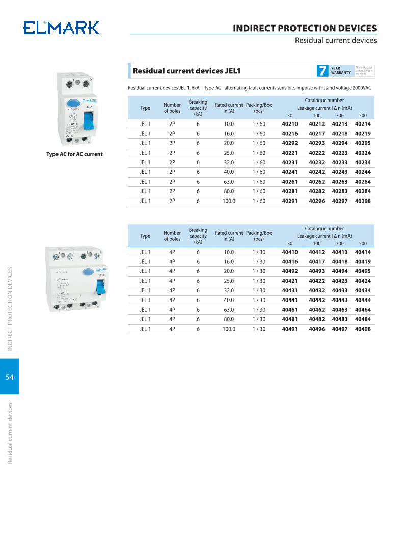
54
INDIRECT PROTECTION DEVICESResidual current devices
IND
IREC
T PR
OTE
CTI
ON
DEV
ICES
Resi
dual
cur
rent
dev
ices
Type AC for AC current
Residual current devices JEL1 *for industrial usage, 3 years warranty7 YEAR
WARRANTY
Residual current devices JЕL 1, 6kA - Type АС - alternating fault currents sensible. Impulse withstand voltage 2000VAC
Type Number of poles
Breaking capacity
(kA)
Rated currentIn (A)
Packing/Box (pcs)
Catalogue number
Leakage current I Δ n (mA)30 100 300 500
JEL 1 2P 6 10.0 1 / 60 40210 40212 40213 40214
JEL 1 2P 6 16.0 1 / 60 40216 40217 40218 40219
JEL 1 2P 6 20.0 1 / 60 40292 40293 40294 40295
JEL 1 2P 6 25.0 1 / 60 40221 40222 40223 40224
JEL 1 2P 6 32.0 1 / 60 40231 40232 40233 40234
JEL 1 2P 6 40.0 1 / 60 40241 40242 40243 40244
JEL 1 2P 6 63.0 1 / 60 40261 40262 40263 40264
JEL 1 2P 6 80.0 1 / 60 40281 40282 40283 40284
JEL 1 2P 6 100.0 1 / 60 40291 40296 40297 40298
Type Number of poles
Breaking capacity
(kA)
Rated currentIn (A)
Packing/Box (pcs)
Catalogue number
Leakage current I Δ n (mA)30 100 300 500
JEL 1 4P 6 10.0 1 / 30 40410 40412 40413 40414
JEL 1 4P 6 16.0 1 / 30 40416 40417 40418 40419
JEL 1 4P 6 20.0 1 / 30 40492 40493 40494 40495
JEL 1 4P 6 25.0 1 / 30 40421 40422 40423 40424
JEL 1 4P 6 32.0 1 / 30 40431 40432 40433 40434
JEL 1 4P 6 40.0 1 / 30 40441 40442 40443 40444
JEL 1 4P 6 63.0 1 / 30 40461 40462 40463 40464
JEL 1 4P 6 80.0 1 / 30 40481 40482 40483 40484
JEL 1 4P 6 100.0 1 / 30 40491 40496 40497 40498
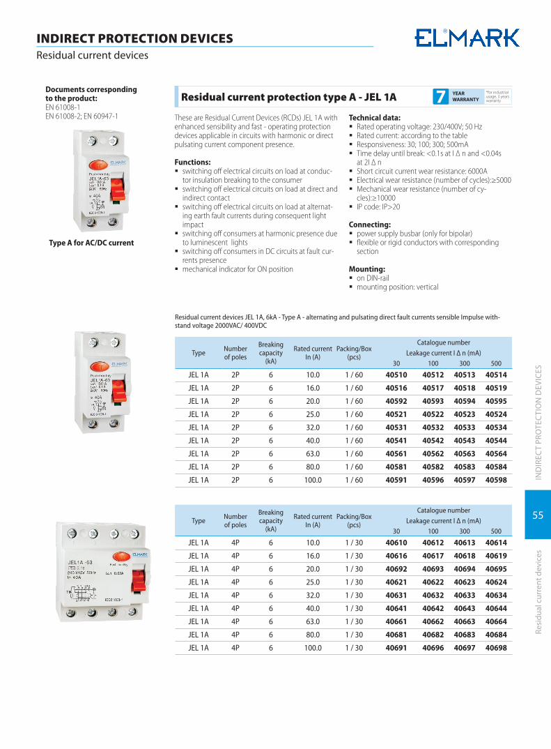
55
INDIRECT PROTECTION DEVICESResidual current devices
IND
IREC
T PR
OTE
CTI
ON
DEV
ICES
Resi
dual
cur
rent
dev
ices
Residual current protection type A - JEL 1A*for industrial usage, 3 years warranty7 YEAR
WARRANTY
These are Residual Current Devices (RCDs) JEL 1A with enhanced sensibility and fast - operating protection devices applicable in circuits with harmonic or direct pulsating current component presence.
Functions: � switching off electrical circuits on load at conduc-
tor insulation breaking to the consumer � switching off electrical circuits on load at direct and
indirect contact � switching off electrical circuits on load at alternat-
ing earth fault currents during consequent light impact
� switching off consumers at harmonic presence due to luminescent lights
� switching off consumers in DC circuits at fault cur-rents presence
� mechanical indicator for ON position
Technical data: � Rated operating voltage: 230/400V; 50 Hz � Rated current: according to the table � Responsiveness: 30; 100; 300; 500mA � Time delay until break: <0.1s at I Δ n and <0.04s
at 2I Δ n � Short circuit current wear resistance: 6000А � Electrical wear resistance (number of cycles):≥5000 � Mechanical wear resistance (number of cy-
cles):≥10000 � IP code: IP>20
Connecting: � power supply busbar (only for bipolar) � flexible or rigid conductors with corresponding
section
Mounting: � on DIN-rail � mounting position: vertical
Type A for AC/DC current
Documents correspondingto the product:EN 61008-1EN 61008-2; EN 60947-1
Residual current devices JЕL 1A, 6kA - Type А - alternating and pulsating direct fault currents sensible Impulse with-stand voltage 2000VAC/ 400VDC
Type Number of poles
Breaking capacity
(kA)
Rated currentIn (A)
Packing/Box (pcs)
Catalogue number
Leakage current I Δ n (mA)30 100 300 500
JEL 1A 2P 6 10.0 1 / 60 40510 40512 40513 40514
JEL 1A 2P 6 16.0 1 / 60 40516 40517 40518 40519
JEL 1A 2P 6 20.0 1 / 60 40592 40593 40594 40595
JEL 1A 2P 6 25.0 1 / 60 40521 40522 40523 40524
JEL 1A 2P 6 32.0 1 / 60 40531 40532 40533 40534
JEL 1A 2P 6 40.0 1 / 60 40541 40542 40543 40544
JEL 1A 2P 6 63.0 1 / 60 40561 40562 40563 40564
JEL 1A 2P 6 80.0 1 / 60 40581 40582 40583 40584
JEL 1A 2P 6 100.0 1 / 60 40591 40596 40597 40598
Type Number of poles
Breaking capacity
(kA)
Rated currentIn (A)
Packing/Box (pcs)
Catalogue number
Leakage current I Δ n (mA)30 100 300 500
JEL 1A 4P 6 10.0 1 / 30 40610 40612 40613 40614
JEL 1A 4P 6 16.0 1 / 30 40616 40617 40618 40619
JEL 1A 4P 6 20.0 1 / 30 40692 40693 40694 40695
JEL 1A 4P 6 25.0 1 / 30 40621 40622 40623 40624
JEL 1A 4P 6 32.0 1 / 30 40631 40632 40633 40634
JEL 1A 4P 6 40.0 1 / 30 40641 40642 40643 40644
JEL 1A 4P 6 63.0 1 / 30 40661 40662 40663 40664
JEL 1A 4P 6 80.0 1 / 30 40681 40682 40683 40684
JEL 1A 4P 6 100.0 1 / 30 40691 40696 40697 40698

56
IND
IREC
T PR
OTE
CTI
ON
DEV
ICES
INDIRECT PROTECTION DEVICESCombined residual current devices
Com
bine
d re
sidu
al c
urre
nt d
evic
es
Type AC for AC current
Combined circuit breakers with residual current devices(RCD)-JEL5
*for industrial usage, 3 years warranty7 YEAR
WARRANTY
Description of the operating system:It is a combination of automatic circuit breaker and residual current electromagnetic device. It combines the properties of the two elements. The circuit breaker reacts at short circuit or overload in the protected cir-cuit, and the electromagnetic residual current device - at failure in the conductors’ insulation. It compares the magnitude of the currents through the neutral and phase conductors. The conductors are coiled on toroid and together with the secondary winding form a measurement transformer. The power conductors are coiled in such a way that the magnetic fields generated at electrical current flow through them are mutually neutralized. At failure in the insulation of some of the conductors or at presence of a person under voltage, the system is misbalanced and the magnetic fields can not be neutralized. This residual magnetic field generates in the secondary current winding, called current leakage. When the value of this current exceeds the limit value of the residual current breaker the device breaks and the residual current device switches off from the power supply grid. The device operates without any extra power supply to the electromagnetic residual current and is not influenced by voltage varying or decreasing.
Functions: � switching off heavy-loaded electrical circuits at
short circuit or overload � switching off heavy-loaded electrical circuits
at insulation damage of the conductors to the consumers
� switching off heavy-loaded electrical circuits at presence of a person and animals under voltage
� used to protect not only particular consumers/circuits, but also the whole panel
� remarkable with high reliability of current charac-teristics
� control: manual switching on and automatic switching off at failure in the insulation after the breaker
Technical data: � Rated operating voltage: 230V 50 Hz � Circuit breaker rated current: according to the table � Residual current responsiveness: 30; 100; 300;
500mA � Time delay until break:
à of the residual current device: <0.1s at I Δ n and <0.04s at 2I Δ n
à of the circuit breaker: <0.1s � Circuit breaker tripping curve: C � Surge voltage wear resistance:≥2000V � Breaking capacity: 10000 � Joining terminal: flat (tunnel) screw terminal made
of 1.5 coldly draw-plated plane Q235A � Type of the plastic:
à material: self-extinguishing nylon PA66 à dielectrical strength: >18MV/m
� Contact head: silver graphite CAg(5) � Static contact: pure copper T2Y2 type � Electrical wear resistance (number of cycles):≥5000 � Mechanical wear resistance (number of cy-
cles):≥10000 � IP code: IP>20 � Indication for operating (switched on) position � Breakers plastic material of UV rays and non-
flammable � Ambient temperature: -10°C + 65°C � Installation altitude: up to 2000m
Connecting: � flexible or rigid conductors with corresponding
section
Mounting: � on DIN-rail � mounting position: vertical
The residual current device is mounted in the distribu-tion box, and after the device the neutral conductor and the earthing conductor must not be connected together. In order to work accurately, the device must have three- or five-conductor grid with separate op-erating neutral conductor (N) and separate protecting conductor (PE) (e.g. earthing system TN-S or TT with three or five conductors).
Dimensions (mm)
W1 H C1 C2 D1 D2
35 81 35 45 50 72
Documents correspondingto the product:EN 61 009-1; EN 61009-2;
Combined electromagnetic residual current device and circuit breaker 2P 6kA
Typedesignation
Number of poles
Breakingcapacity
(kA)
Rated current
(A)
Packing / Box (pcs)
Catalogue numberLeakage current I Δ n (mA)
30 100 300 500
JEL5 2 6 10 7 / 140 40010 40011 40013 40015
JEL5 2 6 16 7 / 140 40016 40017 40018 40019
JEL5 2 6 25 7 / 140 40025 40021 40023 40026
JEL5 2 6 32 7 / 140 40032 40031 40033 40035
JEL5 2 6 40 7 / 140 40040 40041 40043 40045
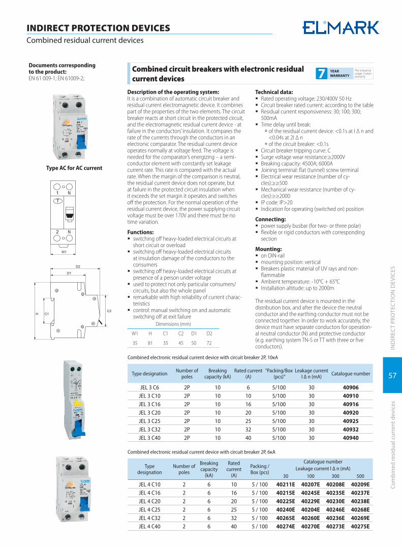
57
IND
IREC
T PR
OTE
CTI
ON
DEV
ICES
INDIRECT PROTECTION DEVICESCombined residual current devices
Com
bine
d re
sidu
al c
urre
nt d
evic
es
Dimensions (mm)
W1 H C1 C2 D1 D2
35 81 35 45 50 72
Combined circuit breakers with electronic residual current devices
*for industrial usage, 3 years warranty7 YEAR
WARRANTY
Description of the operating system:It is a combination of automatic circuit breaker and residual current electromagnetic device. It combines part of the properties of the two elements. The circuit breaker reacts at short circuit in the protected circuit, and the electromagnetic residual current device - at failure in the conductors’ insulation. It compares the rate of the currents through the conductors in an electronic comparator. The residual current device operates normally at voltage feed. The voltage is needed for the comparator’s energizing – a semi-conductor element with constantly set leakage current rate. This rate is compared with the actual rate. When the margin of the comparison is neutral, the residual current device does not operate, but at failure in the protected circuit insulation when it exceeds the set margin it operates and switches off the protection. For the normal operation of the residual current device, the power supplying circuit voltage must be over 170V and there must be no time variation.
Functions: � switching off heavy-loaded electrical circuits at
short circuit or overload � switching off heavy-loaded electrical circuits
at insulation damage of the conductors to the consumers
� switching off heavy-loaded electrical circuits at presence of a person under voltage
� used to protect not only particular consumers/circuits, but also the whole panel
� remarkable with high reliability of current charac-teristics
� control: manual switching on and automatic switching off at exit failure
Technical data: � Rated operating voltage: 230/400V 50 Hz � Circuit breaker rated current: according to the table � Residual current responsiveness: 30; 100; 300;
500mA � Time delay until break:
à of the residual current device: <0.1s at I Δ n and <0.04s at 2I Δ n
à of the circuit breaker: <0.1s � Circuit breaker tripping curve: C � Surge voltage wear resistance:≥2000V � Breaking capacity: 4500A; 6000А � Joining terminal: flat (tunnel) screw terminal � Electrical wear resistance (number of cy-
cles):≥≥500 � Mechanical wear resistance (number of cy-
cles):≥≥2000 � IP code: IP>20 � Indication for operating (switched on) position
Connecting: � power supply busbar (for two- or three polar) � flexible or rigid conductors with corresponding
section
Mounting: � on DIN-rail � mounting position: vertical � Breakers plastic material of UV rays and non-
flammable � Ambient temperature: -10°C + 65°C � Installation altitude: up to 2000m
The residual current device is mounted in the distribution box, and after the device the neutral conductor and the earthing conductor must not be connected together. In order to work accurately, the device must have separate conductors for operation-al neutral conductor (N) and protective conductor (e.g. earthing system TN-S or TT with three or five conductors).
Documents correspondingto the product:EN 61 009-1; EN 61009-2;
Type AC for AC current
Combined electronic residual current device with circuit breaker 2P, 10кА
Type designation Number of poles
Breaking capacity (kA)
Rated current (A)
"Packing/Box (pcs)"
Leakage current I Δ n (mA) Catalogue number
JEL 3 C6 2P 10 6 5/100 30 40906JEL 3 C10 2P 10 10 5/100 30 40910JEL 3 C16 2P 10 16 5/100 30 40916JEL 3 C20 2P 10 20 5/100 30 40920JEL 3 C25 2P 10 25 5/100 30 40925JEL 3 C32 2P 10 32 5/100 30 40932JEL 3 C40 2P 10 40 5/100 30 40940
Combined electronic residual current device with circuit breaker 2P, 6кА
Typedesignation
Number of poles
Breakingcapacity
(kA)
Rated current
(A)
Packing / Box (pcs)
Catalogue numberLeakage current I Δ n (mA)
30 100 300 500
JEL 4 C10 2 6 10 5 / 100 40211E 40207E 40208E 40209EJEL 4 C16 2 6 16 5 / 100 40215E 40245E 40235E 40237EJEL 4 C20 2 6 20 5 / 100 40225E 40229E 40230E 40238EJEL 4 C25 2 6 25 5 / 100 40240E 40204E 40246E 40268EJEL 4 C32 2 6 32 5 / 100 40265E 40260E 40236E 40269EJEL 4 C40 2 6 40 5 / 100 40274E 40270E 40273E 40275E
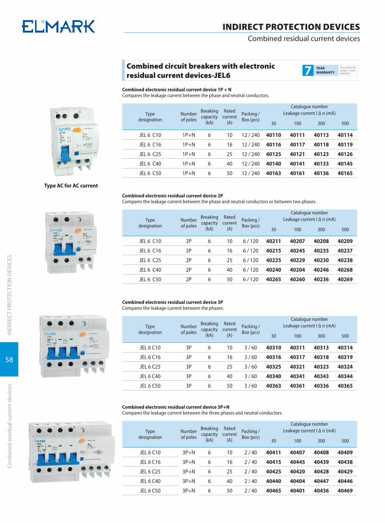
58
IND
IREC
T PR
OTE
CTI
ON
DEV
ICES
INDIRECT PROTECTION DEVICESCombined residual current devices
Com
bine
d re
sidu
al c
urre
nt d
evic
es
Combined circuit breakers with electronic residual current devices-JEL6
*for industrial usage, 3 years warranty7 YEAR
WARRANTY
Type AC for AC current
Combined electronic residual current device 1P + NCompares the leakage current between the phase and neutral conductors.
Typedesignation
Number of poles
Breakingcapacity
(kA)
Rated current
(A)
Packing / Box (pcs)
Catalogue numberLeakage current I Δ n (mA)
30 100 300 500
JEL 6 C10 1P+N 6 10 12 / 240 40110 40111 40113 40114
JEL 6 C16 1P+N 6 16 12 / 240 40116 40117 40118 40119
JEL 6 C25 1P+N 6 25 12 / 240 40125 40121 40123 40126
JEL 6 C40 1P+N 6 40 12 / 240 40140 40141 40133 40145
JEL 6 C50 1P+N 6 50 12 / 240 40163 40161 40136 40165
Combined electronic residual current device 2PCompares the leakage current between the phase and neutral conductors or between two phases.
Typedesignation
Number of poles
Breakingcapacity
(kA)
Rated current
(A)
Packing / Box (pcs)
Catalogue numberLeakage current I Δ n (mA)
30 100 300 500
JEL 6 C10 2P 6 10 6 / 120 40211 40207 40208 40209
JEL 6 C16 2P 6 16 6 / 120 40215 40245 40235 40237
JEL 6 C25 2P 6 25 6 / 120 40225 40229 40230 40238
JEL 6 C40 2P 6 40 6 / 120 40240 40204 40246 40268
JEL 6 C50 2P 6 50 6 / 120 40265 40260 40236 40269
Combined electronic residual current device 3PCompares the leakage current between the phases.
Typedesignation
Number of poles
Breakingcapacity
(kA)
Rated current
(A)
Packing / Box (pcs)
Catalogue numberLeakage current I Δ n (mA)
30 100 300 500
JEL 6 C10 3P 6 10 3 / 60 40310 40311 40313 40314
JEL 6 C16 3P 6 16 3 / 60 40316 40317 40318 40319
JEL 6 C25 3P 6 25 3 / 60 40325 40321 40323 40324
JEL 6 C40 3P 6 40 3 / 60 40340 40341 40343 40344
JEL 6 C50 3P 6 50 3 / 60 40363 40361 40336 40365
Combined electronic residual current device 3P+NCompares the leakage current between the three phases and neutral conductors.
Typedesignation
Number of poles
Breakingcapacity
(kA)
Rated current
(A)
Packing / Box (pcs)
Catalogue numberLeakage current I Δ n (mA)
30 100 300 500
JEL 6 C10 3P+N 6 10 2 / 40 40411 40407 40408 40409
JEL 6 C16 3P+N 6 16 2 / 40 40415 40445 40439 40438
JEL 6 C25 3P+N 6 25 2 / 40 40425 40420 40428 40429
JEL 6 C40 3P+N 6 40 2 / 40 40440 40404 40447 40446
JEL 6 C50 3P+N 6 50 2 / 40 40465 40401 40436 40469

59
IND
IREC
T PR
OTE
CTI
ON
DEV
ICES
Surg
e ar
rest
ers
INDIRECT PROTECTION DEVICESSurge arresters
Type AC for AC current
Documents corresponding to the product:Standard EN61 643-1
The breakers are in accordance with the directives of EC “Low voltage directives (LVD) no. 2006/95/EC and “Electromag-netic Compatibility Directives (EMC) no. 2004/108/EC.
Surge arresters SPD type*for industrial usage, 3 years warranty7 YEAR
WARRANTY
The surge arrester consists of a semi-conductor valve element that opens at certain conditions. At normal conditions of the system, the surge arrester has infinitely high resistance between the protected conductors and earthing circuit. At voltage increase due to atmospheric nature or system failure, the valve element opens and leads the excessive voltage to the grounded circuit.After reversion of the normal voltage the valve ele-ment closes. The arrester can endure high momentary overloading.
Functions: � protection of heavy-loaded electrical circuits from
overload � used to protect not only particular consumers/
circuits, but also the whole panel � remarkable with high reliability of current charac-
teristics � control: automatic switching off at exit failure and
recovery after eliminating the danger
Technical data: � Rated operating voltage Uc: - the operating voltage
of the surge arrester 275/440V; 50Hz � Surge voltage Up: the voltage created in surge ar-
rester terminals at rated discharge current running: according to the tables
� Rated discharge current In – the rated value of discharge current with a sinusoid 8/20μs, which can be repeatedly led to the ground: according to the tables
� Full discharge current Imax – the peak value of the discharge current with a sinusoid 8/20μs, which the surge arrester can bear once: according to the table
� Constant operating current: up to 800μA for 1P, 2P and 3P; up to 600μA for 1P + N, 3P + N
� Indication for damaged surge arrester � Offered in types: 1P; 1P + N; 3P; 3P + N
Connecting: � flexible or rigid conductors with corresponding
section
Mounting: � on DIN-rail � mounting position: vertical � mounting in the distribution box on the front or
right before the breaker according to the attached schemes
� Breakers plastic material of UV rays and non-flammable
� Ambient temperature: -10°C + 65°C � Installation altitude: up to 2000m
COLOUR CODE for all types 5кА - yellow; white – 10кА; green – 20 кА and red 40кА
The surge arrester selection is made according to the overload risk level or atmosphere activity, named B, C or D (from high to low risk level).
The company offers the following models of arresters:Model SPD – Bxxxx – for systems with exceptionally high risk level. Mounted mainly in the beginning of the installation or in the main panel.Model SPD – Cxxxx – for systems with high or average risk level. Mounted in the beginning of the installation or before the breaker.Model SPD – Dxxxx – for systems with low risk level. Suitable for secondary protection of consumers in combi-nation with SPD – Bxxxx/SPD – Cxxxx
Dimensions (mm)
C H1 H2 D1 D2
5 90 45 43,5 58
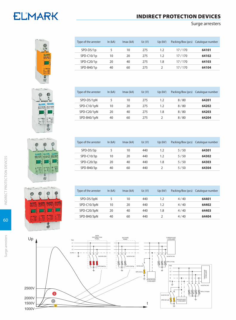
60
IND
IREC
T PR
OTE
CTI
ON
DEV
ICES
Surg
e ar
rest
ers
INDIRECT PROTECTION DEVICESSurge arresters
Type of the arrester In (kA) Imax (kA) Uc (V) Up (kV) Packing/Box (pcs) Catalogue number
SPD-D5/1p 5 10 275 1.2 17 / 170 64101
SPD-C10/1p 10 20 275 1.2 17 / 170 64102
SPD-C20/1p 20 40 275 1.8 17 / 170 64103
SPD-B40/1p 40 60 275 2 17 / 170 64104
Type of the arrester In (kA) Imax (kA) Uc (V) Up (kV) Packing/Box (pcs) Catalogue number
SPD-D5/1pN 5 10 275 1.2 8 / 80 64201
SPD-C10/1pN 10 20 275 1.2 8 / 80 64202
SPD-C20/1pN 20 40 275 1.8 8 / 80 64203
SPD-B40/1pN 40 60 275 2 8 / 80 64204
Type of the arrester In (kA) Imax (kA) Uc (V) Up (kV) Packing/Box (pcs) Catalogue number
SPD-D5/3p 5 10 440 1.2 5 / 50 64301
SPD-C10/3p 10 20 440 1.2 5 / 50 64302
SPD-C20/3p 20 40 440 1.8 5 / 50 64303
SPD-B40/3p 40 60 440 2 5 / 50 64304
Type of the arrester In (kA) Imax (kA) Uc (V) Up (kV) Packing/Box (pcs) Catalogue number
SPD-D5/3pN 5 10 440 1.2 4 / 40 64401
SPD-C10/3pN 10 20 440 1.2 4 / 40 64402
SPD-C20/3pN 20 40 440 1.8 4 / 40 64403
SPD-B40/3pN 40 60 440 2 4 / 40 64404

61
IND
IREC
T PR
OTE
CTI
ON
DEV
ICES
Surg
e ar
rest
ers
INDIRECT PROTECTION DEVICESSurge arresters
Combined surge arresters AC – DC*for industrial usage, 3 years warranty7 YEAR
WARRANTY
Specially designed surge arresters providing protection of solar and photo - voltaic systems; designed to protect system against overvoltages resulting from indirect light impact. They could be installed in earthed and non - earthed systems. They break photo - voltaic generator electric circuit when voltage reaches or over passes limit threshold value, providing photo - voltaic protection against destroying.
COLOUR CODE for all types 5кА - yellow; white – 10кА; green – 20 кА and red 30кА
Type AC for AC/DC current
Type of the arrester In (kA) Imax (kA) Uc (V) Up (kV) Packing/Box (pcs)
Catalogue number
SPD-DC-D5/1p 5 10 275 AC/440 DC ≤ 1.2 17 / 170 64105
SPD-DC-C10/1p 10 20 275 AC/440 DC ≤ 1.5 17 / 170 64106
SPD-DC-C20/1p 20 40 275 AC/440 DC ≤ 1.8 17 / 170 64107
SPD-DC-B40/1p 30 60 275 AC/440 DC ≤ 2.2 17 / 170 64108
Type of the arrester In (kA) Imax (kA) Uc (V) Up (kV) Packing/Box (pcs)
Catalogue number
SPD-DC-D5/1pN 5 10 275 AC/440 DC ≤ 1.2 8 / 80 64205
SPD-DC-C10/1pN 10 20 275 AC/440 DC ≤ 1.5 8 / 80 64206
SPD-DC-C20/1pN 20 40 275 AC/440 DC ≤ 1.8 8 / 80 64207
SPD-DC-B40/1pN 30 60 275 AC/440 DC ≤ 2.2 8 / 80 64208
Type of the arrester In (kA) Imax (kA) Uc (V) Up (kV) Packing/Box (pcs)
Catalogue number
SPD-DC-D5/3p 5 10 385 AC/500 DC ≤ 1.2 5 / 50 64305
SPD-DC-C10/3p 10 20 385 AC/500 DC ≤ 1.5 5 / 50 64306
SPD-DC-C20/3p 20 40 385 AC/500 DC ≤ 1.8 5 / 50 64307
SPD-DC-B40/3p 30 60 385 AC/500 DC ≤ 2.2 5 / 50 64308
Type of the arrester In (kA) Imax (kA) Uc (V) Up (kV) Packing/Box (pcs)
Catalogue number
SPD-DC-D5/3pN 5 10 385 AC/500 DC ≤ 1.2 4 / 40 64405
SPD-DC-C10/3pN 10 20 385 AC/500 DC ≤ 1.5 4 / 40 64406
SPD-DC-C20/3pN 20 40 385 AC/500 DC ≤ 1.8 4 / 40 64407
SPD-DC-B40/3pN 30 60 385 AC/500 DC ≤ 2.2 4 / 40 64408

CONTACTORSCONTACTORS
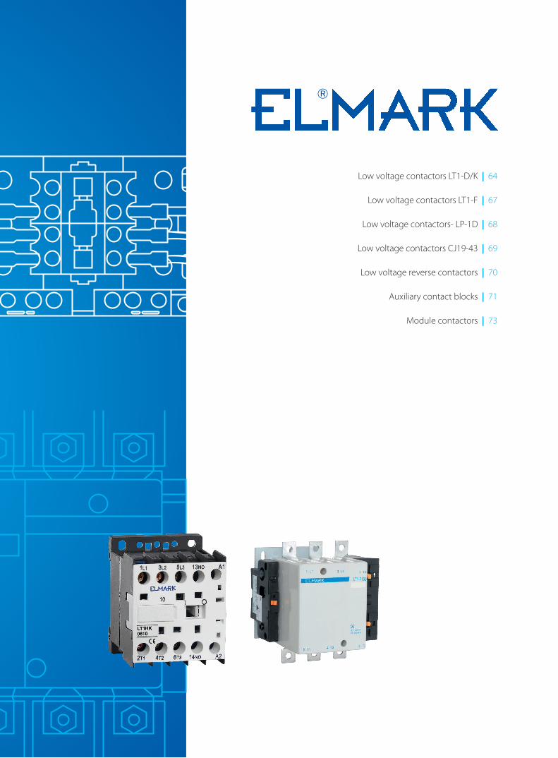
Low voltage contactors LT1-D/K | 64
Low voltage contactors LT1-F | 67
Low voltage contactors- LP-1D | 68
Low voltage contactors CJ19-43 | 69
Low voltage reverse contactors | 70
Auxiliary contact blocks | 71
Module contactors | 73
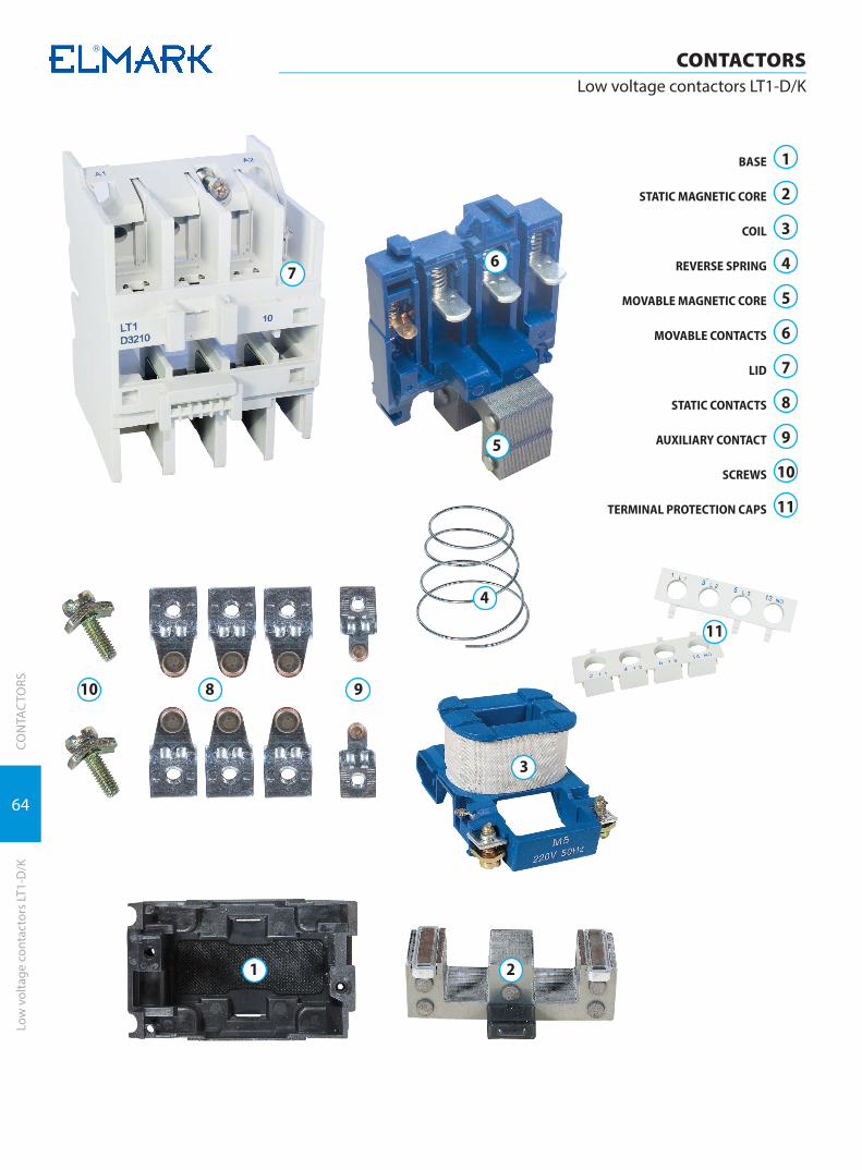
64
CONTACTORSLow voltage contactors LT1-D/K
CON
TAC
TORS
Low
vol
tage
con
tact
ors
LT1-
D/K
BASE
STATIC MAGNETIC CORE
COIL
REVERSE SPRING
MOVABLE MAGNETIC CORE
MOVABLE CONTACTS
LID
STATIC CONTACTS
AUXILIARY CONTACT
SCREWS
TERMINAL PROTECTION CAPS
1
2
3
4
5
6
7
8
9
10
11
10
7
11
98
6
5
4
3
21
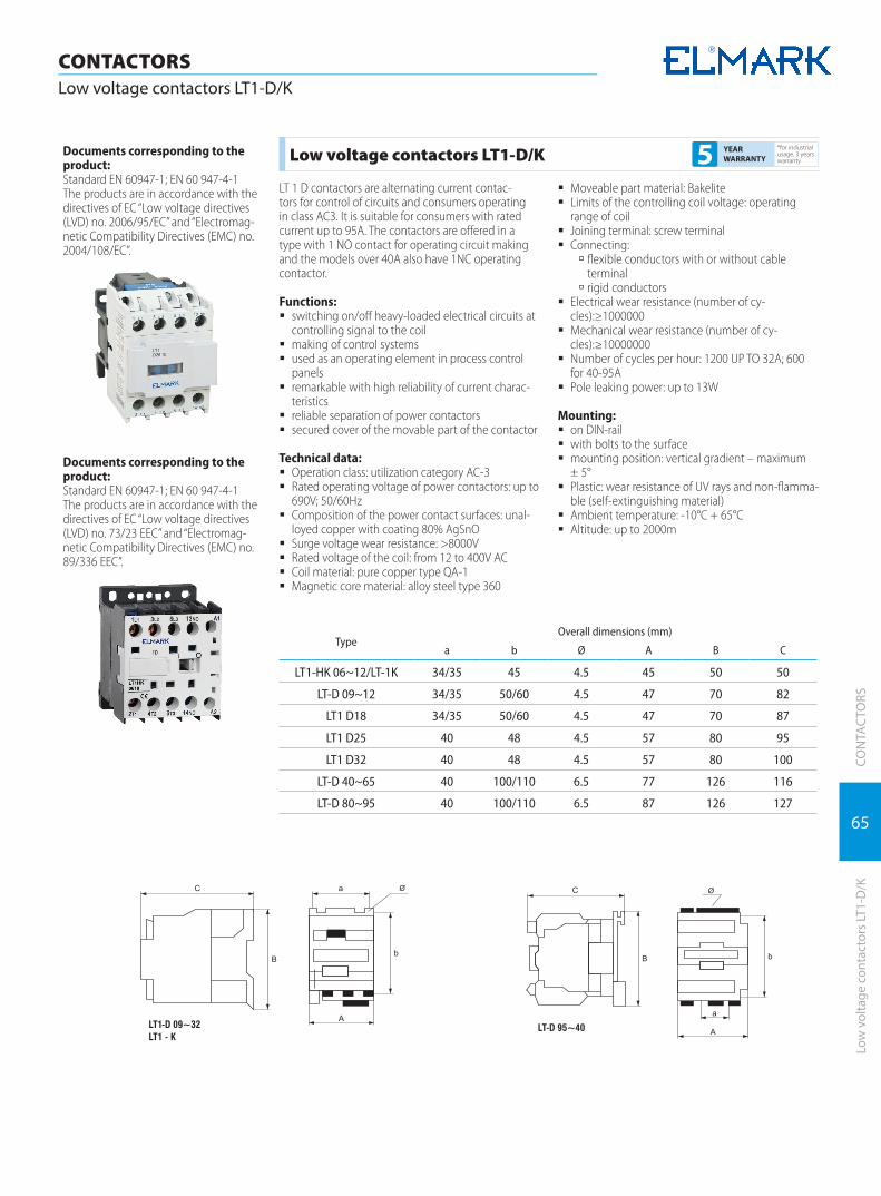
65
CONTACTORSLow voltage contactors LT1-D/K
CON
TAC
TORS
Low
vol
tage
con
tact
ors
LT1-
D/K
Documents corresponding to the product:Standard EN 60947-1; EN 60 947-4-1The products are in accordance with the directives of EC “Low voltage directives (LVD) no. 73/23 EEC” and “Electromag-netic Compatibility Directives (EMC) no. 89/336 EEC”.
Low voltage contactors LT1-D/K*for industrial usage, 3 years warranty5 YEAR
WARRANTY
LT 1 D contactors are alternating current contac-tors for control of circuits and consumers operating in class AC3. It is suitable for consumers with rated current up to 95A. The contactors are offered in a type with 1 NO contact for operating circuit making and the models over 40A also have 1NC operating contactor.
Functions: � switching on/off heavy-loaded electrical circuits at
controlling signal to the coil � making of control systems � used as an operating element in process control
panels � remarkable with high reliability of current charac-
teristics � reliable separation of power contactors � secured cover of the movable part of the contactor
Technical data: � Operation class: utilization category AC-3 � Rated operating voltage of power contactors: up to
690V; 50/60Hz � Composition of the power contact surfaces: unal-
loyed copper with coating 80% AgSnO � Surge voltage wear resistance: >8000V � Rated voltage of the coil: from 12 to 400V AC � Coil material: pure copper type QA-1 � Magnetic core material: alloy steel type 360
� Moveable part material: Bakelite � Limits of the controlling coil voltage: operating
range of coil � Joining terminal: screw terminal � Connecting:
à flexible conductors with or without cable terminal
à rigid conductors � Electrical wear resistance (number of cy-
cles):≥1000000 � Mechanical wear resistance (number of cy-
cles):≥10000000 � Number of cycles per hour: 1200 UP TO 32A; 600
for 40-95A � Pole leaking power: up to 13W
Mounting: � on DIN-rail � with bolts to the surface � mounting position: vertical gradient – maximum
± 5° � Plastic: wear resistance of UV rays and non-flamma-
ble (self-extinguishing material) � Ambient temperature: -10°C + 65°C � Altitude: up to 2000m
Documents corresponding to the product:Standard EN 60947-1; EN 60 947-4-1The products are in accordance with the directives of EC “Low voltage directives (LVD) no. 2006/95/EC” and “Electromag-netic Compatibility Directives (EMC) no. 2004/108/EC”.
TypeOverall dimensions (mm)
a b Ø A B C
LT1-HK 06~12/LT-1K 34/35 45 4.5 45 50 50
LT-D 09~12 34/35 50/60 4.5 47 70 82
LT1 D18 34/35 50/60 4.5 47 70 87
LT1 D25 40 48 4.5 57 80 95
LT1 D32 40 48 4.5 57 80 100
LT-D 40~65 40 100/110 6.5 77 126 116
LT-D 80~95 40 100/110 6.5 87 126 127
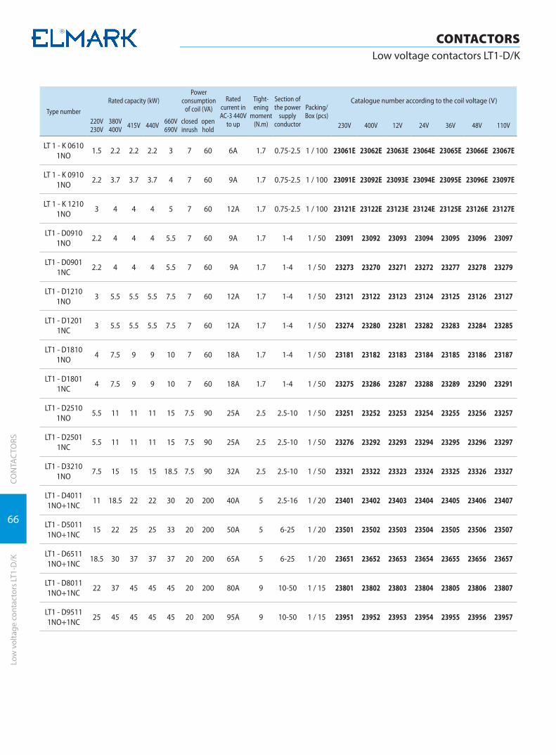
66
CONTACTORSLow voltage contactors LT1-D/K
CON
TAC
TORS
Low
vol
tage
con
tact
ors
LT1-
D/K
Type number
Rated capacity (kW)Power
consumption of coil (VA)
Rated current in AC-3 440V
to up
Tight-ening
moment (N.m)
Section of the power
supply conductor
Packing/Box (pcs)
Catalogue number according to the coil voltage (V)
220V230V
380V400V 415V 440V 660V
690Vclosed inrush
openhold 230V 400V 12V 24V 36V 48V 110V
LT 1 - K 0610 1NO
1.5 2.2 2.2 2.2 3 7 60 6A 1.7 0.75-2.5 1 / 100 23061E 23062E 23063E 23064E 23065E 23066E 23067E
LT 1 - K 0910 1NO
2.2 3.7 3.7 3.7 4 7 60 9A 1.7 0.75-2.5 1 / 100 23091E 23092E 23093E 23094E 23095E 23096E 23097E
LT 1 - K 1210 1NO
3 4 4 4 5 7 60 12A 1.7 0.75-2.5 1 / 100 23121E 23122E 23123E 23124E 23125E 23126E 23127E
LT1 - D0910 1NO
2.2 4 4 4 5.5 7 60 9A 1.7 1-4 1 / 50 23091 23092 23093 23094 23095 23096 23097
LT1 - D0901 1NC
2.2 4 4 4 5.5 7 60 9A 1.7 1-4 1 / 50 23273 23270 23271 23272 23277 23278 23279
LT1 - D1210 1NO
3 5.5 5.5 5.5 7.5 7 60 12A 1.7 1-4 1 / 50 23121 23122 23123 23124 23125 23126 23127
LT1 - D1201 1NC
3 5.5 5.5 5.5 7.5 7 60 12A 1.7 1-4 1 / 50 23274 23280 23281 23282 23283 23284 23285
LT1 - D1810 1NO
4 7.5 9 9 10 7 60 18A 1.7 1-4 1 / 50 23181 23182 23183 23184 23185 23186 23187
LT1 - D1801 1NC
4 7.5 9 9 10 7 60 18A 1.7 1-4 1 / 50 23275 23286 23287 23288 23289 23290 23291
LT1 - D2510 1NO
5.5 11 11 11 15 7.5 90 25A 2.5 2.5-10 1 / 50 23251 23252 23253 23254 23255 23256 23257
LT1 - D2501 1NC
5.5 11 11 11 15 7.5 90 25A 2.5 2.5-10 1 / 50 23276 23292 23293 23294 23295 23296 23297
LT1 - D3210 1NO
7.5 15 15 15 18.5 7.5 90 32A 2.5 2.5-10 1 / 50 23321 23322 23323 23324 23325 23326 23327
LT1 - D4011 1NO+1NC
11 18.5 22 22 30 20 200 40A 5 2.5-16 1 / 20 23401 23402 23403 23404 23405 23406 23407
LT1 - D5011 1NO+1NC
15 22 25 25 33 20 200 50A 5 6-25 1 / 20 23501 23502 23503 23504 23505 23506 23507
LT1 - D6511 1NO+1NC
18.5 30 37 37 37 20 200 65A 5 6-25 1 / 20 23651 23652 23653 23654 23655 23656 23657
LT1 - D8011 1NO+1NC
22 37 45 45 45 20 200 80A 9 10-50 1 / 15 23801 23802 23803 23804 23805 23806 23807
LT1 - D9511 1NO+1NC
25 45 45 45 45 20 200 95A 9 10-50 1 / 15 23951 23952 23953 23954 23955 23956 23957

67
CON
TAC
TORS
Low
vol
tage
con
tact
ors
LT1-
F
CONTACTORSLow voltage contactors LT1-F
Documents corresponding to the product:Standard EN 60947-1; EN 60 947-4-1The products are in accordance with the directives of EC “Low voltage directives (LVD) no. 2006/95/EC” and “Electromag-netic Compatibility Directives (EMC) no. 2004/108/EC”.
TypeOverall dimensions (mm)
A B C L M Q Q1 P
LT 1 F150 163.5 170 171 107 150 26 57.5 40
LT 1 F225 168.5 197 181 113.5 172 21 51.5 48
LT 1 F265 201.5 203 181 141 178 39 66.5 48
LT 1 F400 213 206 219 145 182 43 74 48
LT 1 F630 309 304 255 155 264 60 89 80
LT 1 F800 309 304 255 155 264 60 89 80
Low voltage contactors LT1-F*for industrial usage, 3 years warranty5 YEAR
WARRANTY
The contactors LT 1- F are alternating current contac-tors used to control circuits and consumers operating in normal working conditions with switching on /off the consumer and dirty working environment. They are suitable for consumers with electrical power consumption from 115A to 800A.
Functions: � frequently switching on/off heavy-loaded electrical
circuits at controlling signal to the coil � making of systems for consumers’ control � used as an operating element in process control
panels � remarkable with high reliability of current charac-
teristics � reliable separation of power contactors � secured cover of the movable part of the contactor
Technical data: � Operation class: utilization category AC-3 � Rated operating voltage of power contactors: up to
1000V; 50/60Hz � Composition of the power contact surfaces: unal-
loyed copper with coating 80% AgSnO � Surge voltage wear resistance: >8000V � Coil composition: pure coil copper QA-1 type � Magnetic core composition: steel alloy 360 � Movable part composition: bakelite
� Limits of the controlling coil voltage: operating range of coil
� Joining terminal: screw terminal � Connecting:
à flexible conductors with or without cable terminal
à rigid conductors à rail
� Electrical wear resistance (number of cy-cles):≥10000000
� Mechanical wear resistance (number of cy-cles):≥10000000
� Number of cycles (switching on) per hour: 200 � Pole leaking power: from 16 to 80W � Mounting:
à with bolts to the surface à mounting position: vertical gradient – maxi-mum± 10°C
� Plastic: wear resistance of UV rays and non-flamma-ble (self-extinguishing material)
� Ambient temperature: -10°C + 65°C � Altitude: up to 2000m
Type number
Motor rated capacity (kW)Power
consumption of coil (VA)
Rated current in AC-3 440V
to up
Tight-ening
moment (N.m)
Packing/Box (pcs)
Catalogue number according to the coil voltage (V)
220V230V
380V400V 415V 440V 500V 660V
690V 1000V closed open 230V 400V 12V 24V 36V 48V 110V
LT1 - F115 30 55 59 59 59 80 60 45 550 115 A 18 1 / 4 23111 23112 23113 23114 23115 23116 23117
LT1 - F150 40 75 80 80 90 100 65 45 550 150 A 25 1 / 4 23151 23152 23153 23154 23155 23156 23157
LT1 - F225 63 110 110 110 129 129 100 55 805 225 A 35 1 / 2 23861 23862 23863 23864 23865 23866 23867
LT1 - F265 75 132 140 140 160 160 147 10 700 265 A 35 1 / 2 23261 23262 23263 23264 23265 23266 23267
LT1 - F400 110 200 220 250 257 280 185 18 1000 400 A 50 1 / 1 23751 23752
LT1 - F630 200 335 375 400 400 450 450 25 1500 630 A 50 1 / 1 23771 23772
LT1 - F800 250 450 450 450 450 475 450 15 1300 800 A 50 1 / 1 23881 23882
Note: At mounting the containers from the series in control schemes a distance must be provided at the side of the contactor in case of eventual coil change.
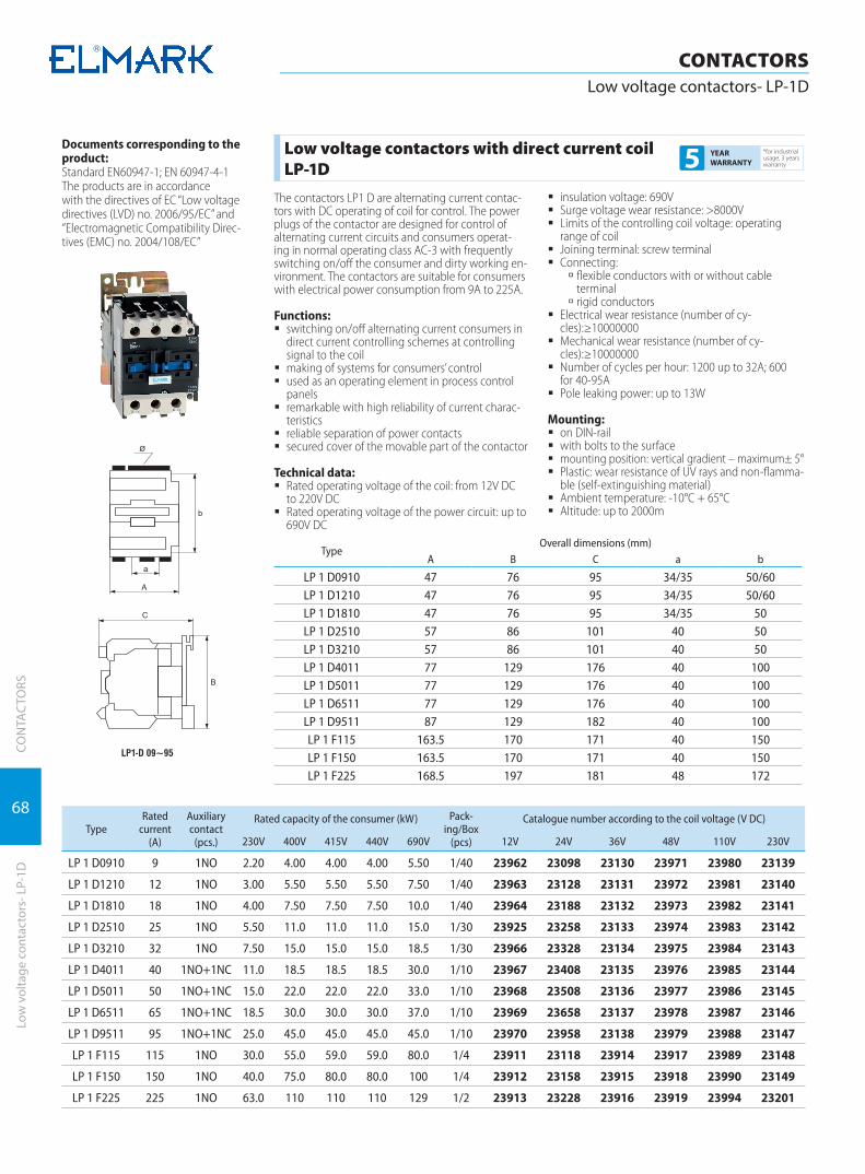
68
CON
TAC
TORS
CONTACTORSLow voltage contactors- LP-1D
Low
vol
tage
con
tact
ors-
LP-
1D
Documents corresponding to the product:Standard EN60947-1; EN 60947-4-1The products are in accordancewith the directives of EC “Low voltage directives (LVD) no. 2006/95/EC” and “Electromagnetic Compatibility Direc-tives (EMC) no. 2004/108/EC”
TypeOverall dimensions (mm)
A B C a b
LP 1 D0910 47 76 95 34/35 50/60LP 1 D1210 47 76 95 34/35 50/60LP 1 D1810 47 76 95 34/35 50LP 1 D2510 57 86 101 40 50LP 1 D3210 57 86 101 40 50LP 1 D4011 77 129 176 40 100LP 1 D5011 77 129 176 40 100LP 1 D6511 77 129 176 40 100LP 1 D9511 87 129 182 40 100LP 1 F115 163.5 170 171 40 150LP 1 F150 163.5 170 171 40 150LP 1 F225 168.5 197 181 48 172
Low voltage contactors with direct current coil LP-1D
*for industrial usage, 3 years warranty5 YEAR
WARRANTY
The contactors LP1 D are alternating current contac-tors with DC operating of coil for control. The power plugs of the contactor are designed for control of alternating current circuits and consumers operat-ing in normal operating class AC-3 with frequently switching on/off the consumer and dirty working en-vironment. The contactors are suitable for consumers with electrical power consumption from 9A to 225A.
Functions: � switching on/off alternating current consumers in
direct current controlling schemes at controlling signal to the coil
� making of systems for consumers’ control � used as an operating element in process control
panels � remarkable with high reliability of current charac-
teristics � reliable separation of power contacts � secured cover of the movable part of the contactor
Technical data: � Rated operating voltage of the coil: from 12V DC
to 220V DC � Rated operating voltage of the power circuit: up to
690V DC
� insulation voltage: 690V � Surge voltage wear resistance: >8000V � Limits of the controlling coil voltage: operating
range of coil � Joining terminal: screw terminal � Connecting:
à flexible conductors with or without cable terminal
à rigid conductors � Electrical wear resistance (number of cy-
cles):≥10000000 � Mechanical wear resistance (number of cy-
cles):≥10000000 � Number of cycles per hour: 1200 up to 32A; 600
for 40-95A � Pole leaking power: up to 13W
Mounting: � on DIN-rail � with bolts to the surface � mounting position: vertical gradient – maximum± 5° � Plastic: wear resistance of UV rays and non-flamma-
ble (self-extinguishing material) � Ambient temperature: -10°C + 65°C � Altitude: up to 2000m
TypeRated
current (А)
Auxiliarycontact
(pcs.)
Rated capacity of the consumer (kW) Pack-ing/Box
(pcs)
Catalogue number according to the coil voltage (V DC)
230V 400V 415V 440V 690V 12V 24V 36V 48V 110V 230V
LP 1 D0910 9 1NO 2.20 4.00 4.00 4.00 5.50 1/40 23962 23098 23130 23971 23980 23139
LP 1 D1210 12 1NO 3.00 5.50 5.50 5.50 7.50 1/40 23963 23128 23131 23972 23981 23140
LP 1 D1810 18 1NO 4.00 7.50 7.50 7.50 10.0 1/40 23964 23188 23132 23973 23982 23141
LP 1 D2510 25 1NO 5.50 11.0 11.0 11.0 15.0 1/30 23925 23258 23133 23974 23983 23142
LP 1 D3210 32 1NO 7.50 15.0 15.0 15.0 18.5 1/30 23966 23328 23134 23975 23984 23143
LP 1 D4011 40 1NO+1NC 11.0 18.5 18.5 18.5 30.0 1/10 23967 23408 23135 23976 23985 23144
LP 1 D5011 50 1NO+1NC 15.0 22.0 22.0 22.0 33.0 1/10 23968 23508 23136 23977 23986 23145
LP 1 D6511 65 1NO+1NC 18.5 30.0 30.0 30.0 37.0 1/10 23969 23658 23137 23978 23987 23146
LP 1 D9511 95 1NO+1NC 25.0 45.0 45.0 45.0 45.0 1/10 23970 23958 23138 23979 23988 23147
LP 1 F115 115 1NO 30.0 55.0 59.0 59.0 80.0 1/4 23911 23118 23914 23917 23989 23148
LP 1 F150 150 1NO 40.0 75.0 80.0 80.0 100 1/4 23912 23158 23915 23918 23990 23149
LP 1 F225 225 1NO 63.0 110 110 110 129 1/2 23913 23228 23916 23919 23994 23201
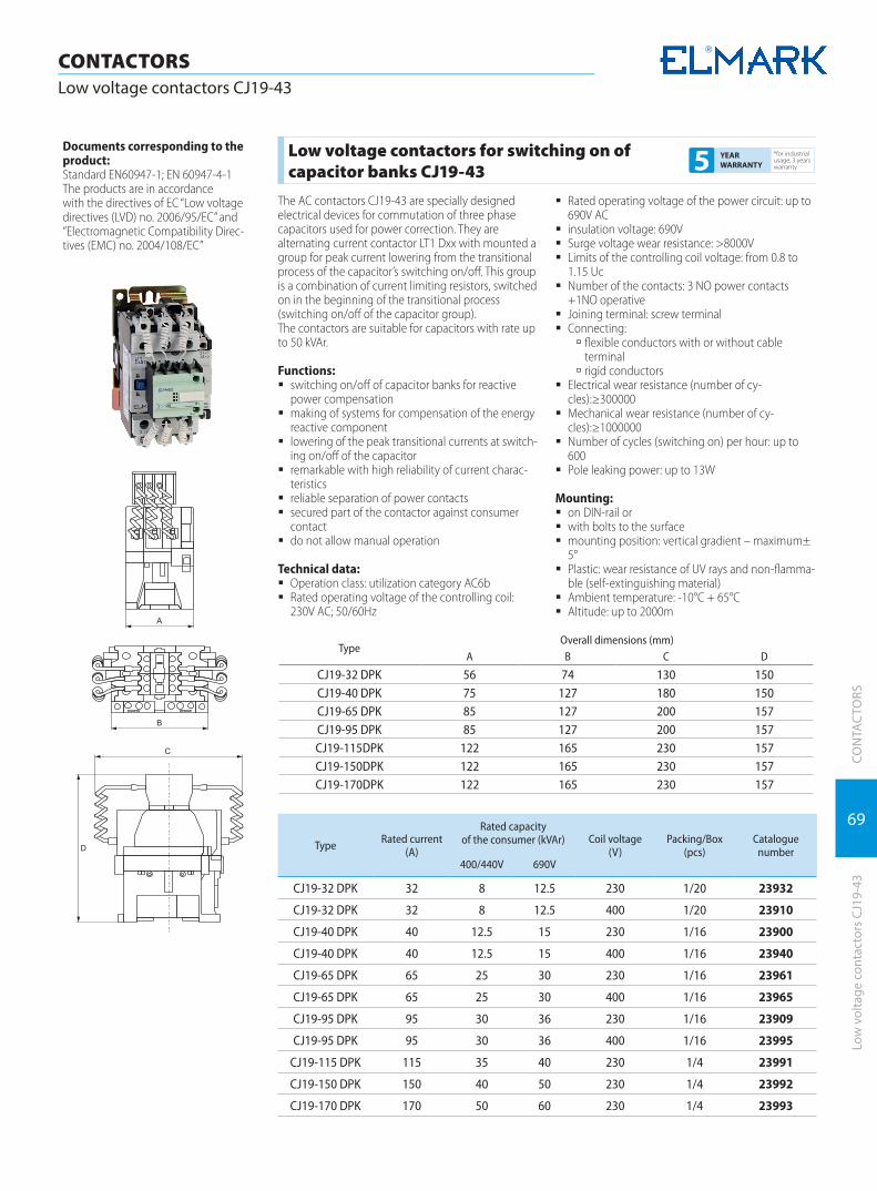
69
CON
TAC
TORS
Low
vol
tage
con
tact
ors
CJ19
-43
CONTACTORSLow voltage contactors CJ19-43
Documents corresponding to the product:Standard EN60947-1; EN 60947-4-1The products are in accordancewith the directives of EC “Low voltage directives (LVD) no. 2006/95/EC” and “Electromagnetic Compatibility Direc-tives (EMC) no. 2004/108/EC”
TypeOverall dimensions (mm)
A B C D
CJ19-32 DPK 56 74 130 150CJ19-40 DPK 75 127 180 150CJ19-65 DPK 85 127 200 157CJ19-95 DPK 85 127 200 157CJ19-115DPK 122 165 230 157CJ19-150DPK 122 165 230 157CJ19-170DPK 122 165 230 157
Low voltage contactors for switching on of capacitor banks CJ19-43
*for industrial usage, 3 years warranty5 YEAR
WARRANTY
The AC contactors CJ19-43 are specially designed electrical devices for commutation of three phase capacitors used for power correction. They are alternating current contactor LT1 Dxx with mounted a group for peak current lowering from the transitional process of the capacitor’s switching on/off. This group is a combination of current limiting resistors, switched on in the beginning of the transitional process (switching on/off of the capacitor group).The contactors are suitable for capacitors with rate up to 50 kVAr.
Functions: � switching on/off of capacitor banks for reactive
power compensation � making of systems for compensation of the energy
reactive component � lowering of the peak transitional currents at switch-
ing on/off of the capacitor � remarkable with high reliability of current charac-
teristics � reliable separation of power contacts � secured part of the contactor against consumer
contact � do not allow manual operation
Technical data: � Operation class: utilization category AC6b � Rated operating voltage of the controlling coil:
230V AC; 50/60Hz
� Rated operating voltage of the power circuit: up to 690V AC
� insulation voltage: 690V � Surge voltage wear resistance: >8000V � Limits of the controlling coil voltage: from 0.8 to
1.15 Uc � Number of the contacts: 3 NO power contacts
+1NO operative � Joining terminal: screw terminal � Connecting:
à flexible conductors with or without cable terminal
à rigid conductors � Electrical wear resistance (number of cy-
cles):≥300000 � Mechanical wear resistance (number of cy-
cles):≥1000000 � Number of cycles (switching on) per hour: up to
600 � Pole leaking power: up to 13W
Mounting: � on DIN-rail or � with bolts to the surface � mounting position: vertical gradient – maximum±
5° � Plastic: wear resistance of UV rays and non-flamma-
ble (self-extinguishing material) � Ambient temperature: -10°C + 65°C � Altitude: up to 2000m
Type Rated current (А)
Rated capacityof the consumer (kVAr) Coil voltage
(V)Packing/Box
(pcs)Catalogue
number400/440V 690V
CJ19-32 DPK 32 8 12.5 230 1/20 23932
CJ19-32 DPK 32 8 12.5 400 1/20 23910
CJ19-40 DPK 40 12.5 15 230 1/16 23900
CJ19-40 DPK 40 12.5 15 400 1/16 23940
CJ19-65 DPK 65 25 30 230 1/16 23961
CJ19-65 DPK 65 25 30 400 1/16 23965
CJ19-95 DPK 95 30 36 230 1/16 23909
CJ19-95 DPK 95 30 36 400 1/16 23995
CJ19-115 DPK 115 35 40 230 1/4 23991
CJ19-150 DPK 150 40 50 230 1/4 23992
CJ19-170 DPK 170 50 60 230 1/4 23993
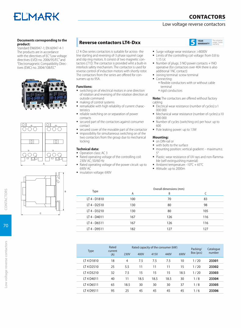
70
CON
TAC
TORS
CONTACTORSLow voltage reverse contactors
Low
vol
tage
reve
rse
cont
acto
rs
Documents corresponding to the product:Standard EN60947-1; EN 60947-4-1The products are in accordancewith the directives of EC “Low voltage directives (LVD) no. 2006/95/EC” and “Electromagnetic Compatibility Direc-tives (EMC) no. 2004/108/EC”
TypeOverall dimensions (mm)
A B C
LT 4 - D1810 100 70 83
LT 4 - D2510 130 80 98
LT 4 - D3210 130 80 105
LT 4 - D4011 167 126 116
LT 4 - D6511 167 126 116
LT 4 - D9511 182 127 127
Reverse contactors LT4-Dxx*for industrial usage, 3 years warranty5 YEAR
WARRANTY
LT 4-Dxx series contactors is suitable for across- the line starting and reversing of-3 phase squirrel cage and slip ring motors. It consist of two magnetic con-tactors LT1D. The contactor is provided whit a built-in interlock safety mechanism. The contactor is used for reverse control of induction motors with shortly rotor.The contactors from the series are offered for con-sumers up to 95A.
Functions: � switching on of electrical motors in one direction
of rotation and reversing of the rotation direction at outside command
� making of control systems � remarkable with high reliability of current charac-
teristics � reliable switching on or separation of power
contacts � secured part of the contactors against consumer
contact � secured cover of the movable part of the contactor � impossibility for simultaneous switching on of the
two contactors from the group due to mechanical locking
Technical data: � Operation class: AC 3 � Rated operating voltage of the controlling coil:
230V AC; 50/60 Hz � Rated operating voltage of the power circuit: up to
690V AC � insulation voltage: 690V
� Surge voltage wear resistance: >8000V � Limits of the controlling coil voltage: from 0.8 to
1.15 Uc � Number of plugs: 3 NO power contacts +1NO
operative (for contactors over 40A there is also additional 1NC contact)
� Joining terminal: screw terminal � Connecting:
à flexible conductors with or without cable terminal
à rigid conductors
Note: The contactors are offered without factory cabling
� Electrical wear resistance (number of cycles):≥1 000 000
� Mechanical wear resistance (number of cycles):≥10 000 000
� Number of cycles (switching on) per hour: up to 600
� Pole leaking power: up to 13W
Mounting: � on DIN-rail or � with bolts to the surface � mounting position: vertical gradient – maximum±
5° � Plastic: wear resistance of UV rays and non-flamma-
ble (self-extinguishing material) � Ambient temperature: -10°C + 65°C � Altitude: up to 2000m
TypeRated
current (А)
Rated capacity of the consumer (kW) Packing/Box (pcs)
Catalogue number230V 400V 415V 440V 690V
LT 4 D1810 18 4 7.5 7.5 7.5 10 1 / 20 23301
LT 4 D2510 25 5.5 11 11 11 15 1 / 20 23302
LT 4 D3210 32 7.5 15 15 15 18.5 1 / 20 23303
LT 4 D4011 40 11 18.5 18.5 18.5 30 1 / 8 23304
LT 4 D6511 65 18.5 30 30 30 37 1 / 8 23305
LT 4 D9511 95 25 45 45 45 45 1 / 6 23306
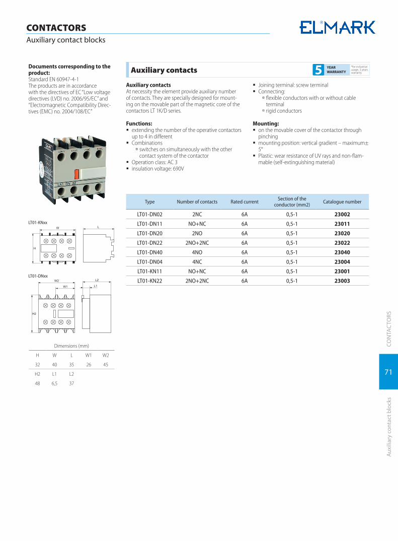
71
CON
TAC
TORS
Auxi
liary
con
tact
blo
cks
CONTACTORSAuxiliary contact blocks
Documents corresponding to the product:Standard EN 60947-4-1The products are in accordancewith the directives of EC “Low voltage directives (LVD) no. 2006/95/EC” and “Electromagnetic Compatibility Direc-tives (EMC) no. 2004/108/EC”
Auxiliary contacts*for industrial usage, 3 years warranty5 YEAR
WARRANTY
Auxiliary contactsAt necessity the element provide auxiliary number of contacts. They are specially designed for mount-ing on the movable part of the magnetic core of the contactors LT 1K/D series.
Functions: � extending the number of the operative contactors
up to 4 in different � Combinations
à switches on simultaneously with the other contact system of the contactor
� Operation class: AC 3 � insulation voltage: 690V
� Joining terminal: screw terminal � Connecting:
à flexible conductors with or without cable terminal
à rigid conductors
Mounting: � on the movable cover of the contactor through
pinching � mounting position: vertical gradient – maximum±
5° � Plastic: wear resistance of UV rays and non-flam-
mable (self-extinguishing material)
Type Number of contacts Rated current Section of the conductor (mm2) Catalogue number
LT01-DN02 2NC 6A 0,5-1 23002
LT01-DN11 NO+NC 6A 0,5-1 23011
LT01-DN20 2NO 6A 0,5-1 23020
LT01-DN22 2NO+2NC 6A 0,5-1 23022
LT01-DN40 4NO 6A 0,5-1 23040
LT01-DN04 4NC 6A 0,5-1 23004
LT01-KN11 NO+NC 6A 0,5-1 23001
LT01-KN22 2NO+2NC 6A 0,5-1 23003
Dimensions (mm)
H W L W1 W2
32 40 35 26 45
H2 L1 L2
48 6,5 37
LT01-KNxx
LT01-DNxx
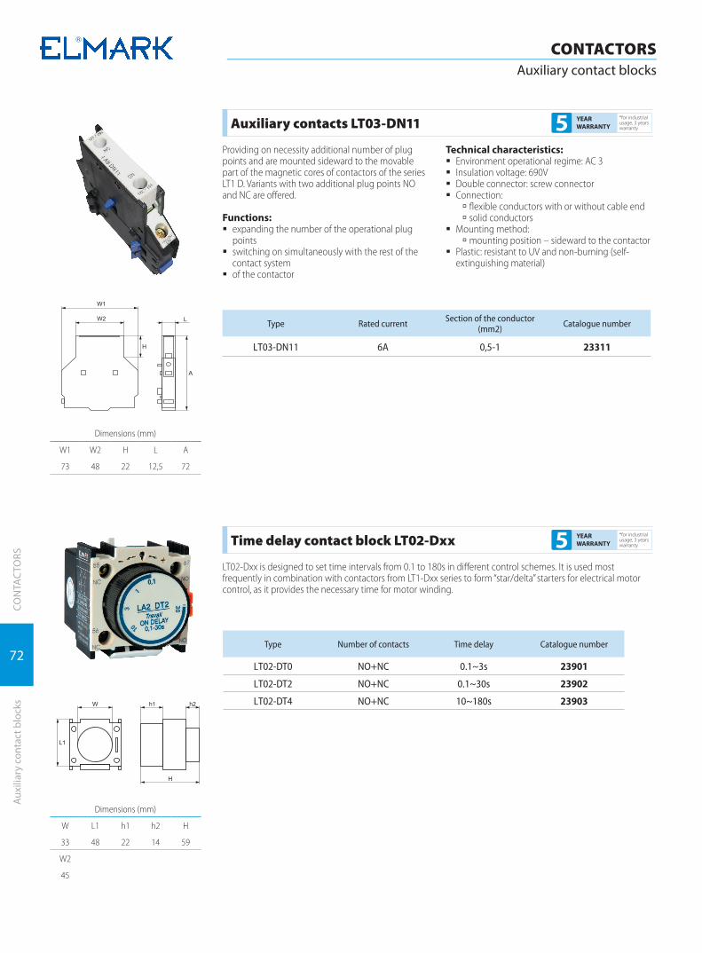
72
CON
TAC
TORS
CONTACTORSAuxiliary contact blocks
Auxi
liary
con
tact
blo
cks
Dimensions (mm)
W1 W2 H L A
73 48 22 12,5 72
Type Rated current Section of the conductor (mm2) Catalogue number
LТ03-DN11 6A 0,5-1 23311
Auxiliary contacts LT03-DN11*for industrial usage, 3 years warranty5 YEAR
WARRANTY
Providing on necessity additional number of plug points and are mounted sideward to the movable part of the magnetic cores of contactors of the series LT1 D. Variants with two additional plug points NO and NC are offered.
Functions: � expanding the number of the operational plug
points � switching on simultaneously with the rest of the
contact system � of the contactor
Technical characteristics: � Environment operational regime: АС 3 � Insulation voltage: 690V � Double connector: screw connector � Connection:
à flexible conductors with or without cable end à solid conductors
� Mounting method: à mounting position – sideward to the contactor
� Plastic: resistant to UV and non-burning (self-extinguishing material)
Dimensions (mm)
W L1 h1 h2 H
33 48 22 14 59
W2
45
Type Number of contacts Time delay Catalogue number
LТ02-DT0 NO+NC 0.1~3s 23901
LТ02-DT2 NO+NC 0.1~30s 23902
LТ02-DT4 NO+NC 10~180s 23903
Time delay contact block LT02-Dxx*for industrial usage, 3 years warranty5 YEAR
WARRANTY
LT02-Dxx is designed to set time intervals from 0.1 to 180s in different control schemes. It is used most frequently in combination with contactors from LT1-Dxx series to form “star/delta” starters for electrical motor control, as it provides the necessary time for motor winding.
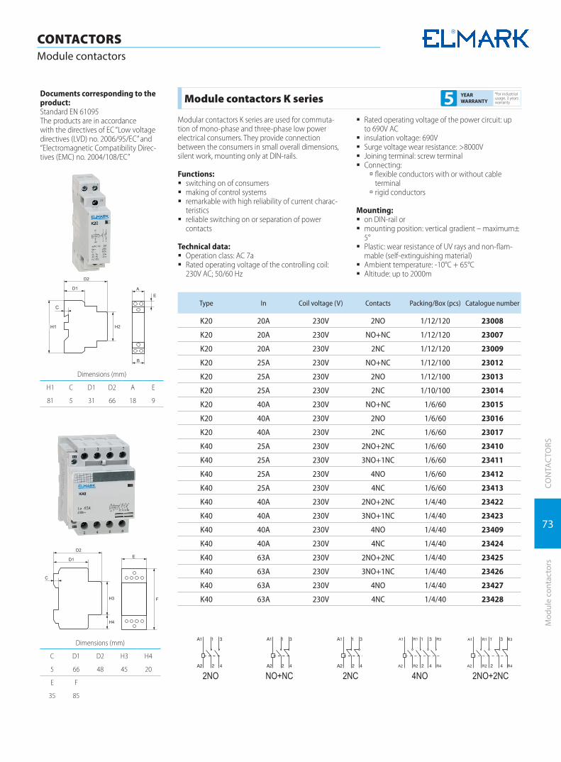
73
CON
TAC
TORS
Mod
ule
cont
acto
rs
CONTACTORSModule contactors
Documents corresponding to the product:Standard EN 61095The products are in accordancewith the directives of EC “Low voltage directives (LVD) no. 2006/95/EC” and “Electromagnetic Compatibility Direc-tives (EMC) no. 2004/108/EC”
Module contactors K series*for industrial usage, 3 years warranty5 YEAR
WARRANTY
Modular contactors K series are used for commuta-tion of mono-phase and three-phase low power electrical consumers. They provide connection between the consumers in small overall dimensions, silent work, mounting only at DIN-rails.
Functions: � switching on of consumers � making of control systems � remarkable with high reliability of current charac-
teristics � reliable switching on or separation of power
contacts
Technical data: � Operation class: AC 7a � Rated operating voltage of the controlling coil:
230V AC; 50/60 Hz
� Rated operating voltage of the power circuit: up to 690V AC
� insulation voltage: 690V � Surge voltage wear resistance: >8000V � Joining terminal: screw terminal � Connecting:
à flexible conductors with or without cable terminal
à rigid conductors
Mounting: � on DIN-rail or � mounting position: vertical gradient – maximum±
5° � Plastic: wear resistance of UV rays and non-flam-
mable (self-extinguishing material) � Ambient temperature: -10°C + 65°C � Altitude: up to 2000m
Type In Coil voltage (V) Contacts Packing/Box (pcs) Catalogue number
K20 20A 230V 2NO 1/12/120 23008
K20 20A 230V NO+NC 1/12/120 23007
K20 20A 230V 2NC 1/12/120 23009
K20 25A 230V NO+NC 1/12/100 23012
K20 25А 230V 2NO 1/12/100 23013
K20 25A 230V 2NC 1/10/100 23014
K20 40A 230V NO+NC 1/6/60 23015
K20 40A 230V 2NO 1/6/60 23016
K20 40A 230V 2NC 1/6/60 23017
K40 25A 230V 2NO+2NC 1/6/60 23410
K40 25A 230V 3NO+1NC 1/6/60 23411
K40 25A 230V 4NO 1/6/60 23412
K40 25A 230V 4NC 1/6/60 23413
K40 40A 230V 2NO+2NC 1/4/40 23422
K40 40A 230V 3NO+1NC 1/4/40 23423
K40 40A 230V 4NO 1/4/40 23409
K40 40A 230V 4NC 1/4/40 23424
K40 63A 230V 2NO+2NC 1/4/40 23425
K40 63A 230V 3NO+1NC 1/4/40 23426
K40 63A 230V 4NO 1/4/40 23427
K40 63A 230V 4NC 1/4/40 23428
Dimensions (mm)
C D1 D2 H3 H4
5 66 48 45 20
E F
35 85
Dimensions (mm)
H1 C D1 D2 A E
81 5 31 66 18 9
H1
C

DEVICESFOR CONTROLAND PROTECTION OF ELECTRICAL MOTORS
DEVICES FOR CONTROLAND PROTECTION OF ELECTRICAL MOTORS
Thermal relays | 76
Thermomagnetic automatic breaker | 78
Auxiliary devices for thermomagnetic automatic breaker | 80
Starters | 81
Frequency inverters | 86
Soft starter | 87
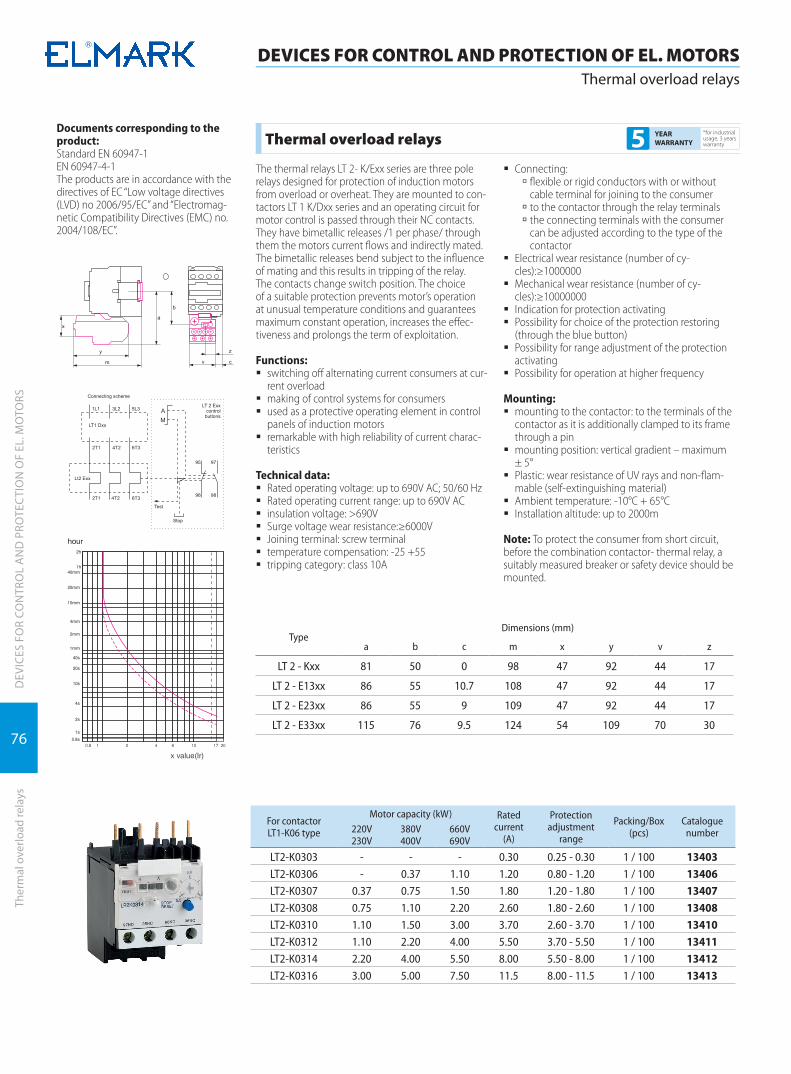
76
DEVICES FOR CONTROL AND PROTECTION OF EL. MOTORSThermal overload relays
DEV
ICES
FO
R CO
NTR
OL
AN
D P
ROTE
CTI
ON
OF
EL. M
OTO
RSTh
erm
al o
verlo
ad re
lays
Documents corresponding to the product:Standard EN 60947-1EN 60947-4-1The products are in accordance with the directives of EC “Low voltage directives (LVD) no 2006/95/EC” and “Electromag-netic Compatibility Directives (EMC) no. 2004/108/EC”.
TypeDimensions (mm)
a b c m x y v z
LT 2 - Kxx 81 50 0 98 47 92 44 17
LT 2 - E13xx 86 55 10.7 108 47 92 44 17
LT 2 - E23xx 86 55 9 109 47 92 44 17
LT 2 - E33xx 115 76 9.5 124 54 109 70 30
Thermal overload relays*for industrial usage, 3 years warranty5 YEAR
WARRANTY
The thermal relays LT 2- K/Exx series are three pole relays designed for protection of induction motors from overload or overheat. They are mounted to con-tactors LT 1 K/Dxx series and an operating circuit for motor control is passed through their NC contacts. They have bimetallic releases /1 per phase/ through them the motors current flows and indirectly mated. The bimetallic releases bend subject to the influence of mating and this results in tripping of the relay. The contacts change switch position. The choice of a suitable protection prevents motor’s operation at unusual temperature conditions and guarantees maximum constant operation, increases the effec-tiveness and prolongs the term of exploitation.
Functions: � switching off alternating current consumers at cur-
rent overload � making of control systems for consumers � used as a protective operating element in control
panels of induction motors � remarkable with high reliability of current charac-
teristics
Technical data: � Rated operating voltage: up to 690V AC; 50/60 Hz � Rated operating current range: up to 690V AC � insulation voltage: >690V � Surge voltage wear resistance:≥6000V � Joining terminal: screw terminal � temperature compensation: -25 +55 � tripping category: class 10A
� Connecting: à flexible or rigid conductors with or without cable terminal for joining to the consumer
à to the contactor through the relay terminals à the connecting terminals with the consumer can be adjusted according to the type of the contactor
� Electrical wear resistance (number of cy-cles):≥1000000
� Mechanical wear resistance (number of cy-cles):≥10000000
� Indication for protection activating � Possibility for choice of the protection restoring
(through the blue button) � Possibility for range adjustment of the protection
activating � Possibility for operation at higher frequency
Mounting: � mounting to the contactor: to the terminals of the
contactor as it is additionally clamped to its frame through a pin
� mounting position: vertical gradient – maximum ± 5°
� Plastic: wear resistance of UV rays and non-flam-mable (self-extinguishing material)
� Ambient temperature: -10°C + 65°C � Installation altitude: up to 2000m
Note: To protect the consumer from short circuit, before the combination contactor- thermal relay, a suitably measured breaker or safety device should be mounted.
For contactorLT1-K06 type
Motor capacity (kW) Rated current
(A)
Protectionadjustment
range
Packing/Box (pcs)
Cataloguenumber220V
230V380V400V
660V690V
LT2-K0303 - - - 0.30 0.25 - 0.30 1 / 100 13403LT2-K0306 - 0.37 1.10 1.20 0.80 - 1.20 1 / 100 13406LT2-K0307 0.37 0.75 1.50 1.80 1.20 - 1.80 1 / 100 13407LT2-K0308 0.75 1.10 2.20 2.60 1.80 - 2.60 1 / 100 13408LT2-K0310 1.10 1.50 3.00 3.70 2.60 - 3.70 1 / 100 13410LT2-K0312 1.10 2.20 4.00 5.50 3.70 - 5.50 1 / 100 13411LT2-K0314 2.20 4.00 5.50 8.00 5.50 - 8.00 1 / 100 13412LT2-K0316 3.00 5.00 7.50 11.5 8.00 - 11.5 1 / 100 13413

77
DEVICES FOR CONTROL AND PROTECTION OF EL. MOTORSThermal overload relays
DEV
ICES
FO
R CO
NTR
OL
AN
D P
ROTE
CTI
ON
OF
EL. M
OTO
RSTh
erm
al o
verlo
ad re
lays
For contactorLT1-D9 to
LT1-D25 type
Motor capacity (kW) Rated current
(A)
Protectionadjustment
range
Packing/Box (pcs)
Cataloguenumber220V
230V380V400V
660V690V
LT2-E1301 - - - 0.16 0.10 - 0.16 1 / 100 13001LT2-E1302 - - - 0.25 0.16 - 0.25 1 / 100 13002LT2-E1303 - - - 0.40 0.25 - 0.40 1 / 100 13003LT2-E1304 - - 0.37 0.63 0.40 - 0.63 1 / 100 13004LT2-E1305 - - 0.55 1.00 0.63 - 1.00 1 / 100 13005LT2-E1306 - 0.37 1.10 1.60 1.0 - 1.60 1 / 100 13006LT2-E1307 0.37 0.75 1.50 2.50 1.6 - 2.50 1 / 100 13007LT2-E1308 0.75 1.50 3.00 4.00 2.5 - 4.00 1 / 100 13008LT2-E1310 1.10 2.20 4.00 6.00 4.0 - 6.00 1 / 100 13010LT2-E1312 2.00 3.70 5.50 8.00 5.5 - 8.00 1 / 100 13012LT2-E1314 2.20 4.00 7.50 10.0 7.0 - 10.0 1 / 100 13014LT2-E1316 3.70 5.50 11.0 13.0 9.0 - 13.0 1 / 100 13016LT2-E1321 4.00 7.50 15.0 18.0 12.0 - 18.0 1 / 100 13021LT2-E1322 5.50 9.00 18.5 25.0 17.0 - 25.0 1 / 100 13022LT2-E1353 9.00 11.0 18.5 33.0 23.0 - 32.0 1 / 100 13053
For contactorLT1-D32 type
Motor capacity (kW) Rated current
(A)
Protectionadjustment
range
Packing/Box (pcs)
Cataloguenumber220V
230V380V400V
660V690V
LT2-E2353 11 11 18.5 32 23.0 - 32.0 1 / 100 13253LT2-E2355 15 15 22.0 36 28.0 - 36.0 1 / 100 13255
For contactorLT1-D40 to
LT1-D95 type
Motor capacity (kW) Rated current
(A)
Protectionadjustment
range
Packing/Box (pcs)
Cataloguenumber220V
230V380V400V
660V690V
LT2-E3355 18.5 18.5 30 40 30.0 - 40.0 1 / 50 13355LT2-E3357 22 22 30 50 37.0 - 50.0 1 / 50 13357LT2-E3359 30 30 37 65 48.0 - 65.0 1 / 50 13359LT2-E3363 45 45 55 80 63.0 - 80.0 1 / 50 13363LT2-E3365 55 55 75 93 80.0 - 93.0 1 / 50 13365
For contactor LT1-F115 to
LT1-F150
Motor capacity (kW) Rated current
(A)
Protectionadjustment
range
Packing/Box (pcs)
Cataloguenumber220V
230V380V400V
660V690V
LT2-F4367 40 75 100 150 90-150 1/30 13367
For contactor LT1-F225 to
LT1-F400
Motor capacity (kW) Rated current
(A)
Protectionadjustment
range
Packing/Box (pcs)
Cataloguenumber220V
230V380V400V
660V690V
LT2-F4368 63 110 129 220 132-220 1/30 13368 LT2-F4369 100 160 220 330 200-330 1/18 13369 LT2-F4370 147 250 335 500 300-500 1/18 13370
For contactor LT1-F630
Motor capacity (kW) Rated current
(A)
Protectionadjustment
range
Packing/Box (pcs)
Cataloguenumber220V
230V380V400V
660V690V
LT2-F4371 200 335 450 630 380-630 1/18 13371

78
DEV
ICES
FO
R CO
NTR
OL
AN
D P
ROTE
CTI
ON
OF
EL. M
OTO
RS
DEVICES FOR CONTROL AND PROTECTION OF EL. MOTORSThermomagnetic automatic breaker
Ther
mom
agne
tic a
utom
atic
bre
aker
Dimensions (mm)
H l1 l2 d D
89 16 50 10 9,2
w1 w2 h1 h2
44,5 18 22 45
Thermomagnetic automatic breaker TM2/TM3*for industrial usage, 3 years warranty5 YEAR
WARRANTY
The thermomagnetic automatic breakers TM 2-Exx series are devices designed for control and protection of induction motors from overload, overheat or short circuit. The overload motor protection is carried out by the built in the breaker thermal elements, and the short circuit protection is carried out by the magnetic elements. These magnetic elements allow the adjust-ment of the current leakage which is 13 times the maximum current of the thermal protection. The overload protection elements include automatic compensation for the ambient temperature changes. In combination with under voltage release the thermomagnetic breaker TM 2-Exx also provides protection of the motors from fall out of a phase from the power supply. The choice of a suitable protection prevents motor’s operation at unusual temperature conditions and guarantees maximum constant operation, increases the effectiveness and prolongs the term of exploitation.
Functions: � switching off alternating current consumers at cur-
rent overload � switching off the electrical circuit to the consumer
at inlet short circuit � protects the motor at lack/lowering of the phase
voltage (if there is under voltage release) � used as a protective operating element in control
panels of induction motors � remarkable with high reliability of current charac-
teristics � possibility for change/choice of the protection
current (according to the operating current of the motor)
� automatic compensation of the ambient tempera-ture
Technical data: � Rated operating voltage: up to 690V AC; 50/60 Hz � Rated operating current range: from 0.1 to 80A
according to the type in table 1 � insulation voltage: 690V � Surge voltage wear resistance:≥6000V � Joining terminal: screw terminal � Connecting:
à flexible or rigid conductors with or without cable terminal for joining to the consumer
à to the contactor through the relay terminals à the connecting terminals with the consumer can be adjusted according to the type of the contactor
� Electrical wear resistance (number of cy-cles):≥1000000
� Mechanical wear resistance (number of cy-cles):≥10000000
� Indication for protection activating � Switching on of the breaker manually with button
“I” and switching off with button “O” manually or automatically at failure or after activating of the protection
� Possibility for range adjustment of the protection activating
� Possibility for operation at higher frequency � Possibility for independent operation or as an ele-
ment of an automation system � tripping category: class 10A
Mounting: � mounting to DIN-rail � mounting position: vertical gradient – maximum±
5° � Plastic: wear resistance of UV rays and non-flam-
mable (self-extinguishing material) � Ambient temperature: -10°C + 65°C � Altitude: up to 2000m
Dimensions
Auxiliarycontact
UVR
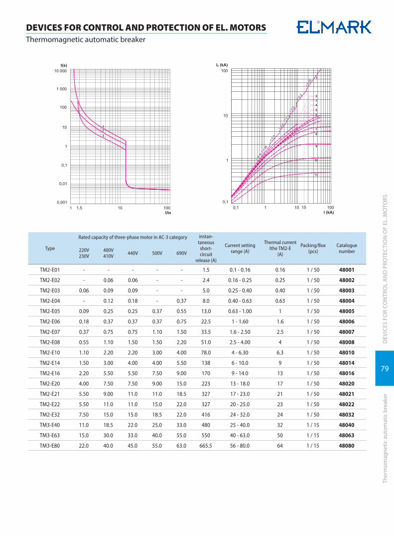
79
DEV
ICES
FO
R CO
NTR
OL
AN
D P
ROTE
CTI
ON
OF
EL. M
OTO
RSTh
erm
omag
netic
aut
omat
ic b
reak
er
DEVICES FOR CONTROL AND PROTECTION OF EL. MOTORSThermomagnetic automatic breaker
Type
Rated capacity of three-phase motor in AC-3 category instan-taneous
short-circuit
release (A)
Current setting range (A)
Thermal currentIthe TM2-E
(A)
Packing/Box (pcs)
Cataloguenumber220V
230V400V410V 440V 500V 690V
TM2-E01 - - - - - 1.5 0.1 - 0.16 0.16 1 / 50 48001
TM2-E02 - 0.06 0.06 - - 2.4 0.16 - 0.25 0.25 1 / 50 48002
TM2-E03 0.06 0.09 0.09 - - 5.0 0.25 - 0.40 0.40 1 / 50 48003
TM2-E04 - 0.12 0.18 - 0.37 8.0 0.40 - 0.63 0.63 1 / 50 48004
TM2-E05 0.09 0.25 0.25 0.37 0.55 13.0 0.63 - 1.00 1 1 / 50 48005
TM2-E06 0.18 0.37 0.37 0.37 0.75 22.5 1 - 1.60 1.6 1 / 50 48006
TM2-E07 0.37 0.75 0.75 1.10 1.50 33.5 1.6 - 2.50 2.5 1 / 50 48007
TM2-E08 0.55 1.10 1.50 1.50 2.20 51.0 2.5 - 4.00 4 1 / 50 48008
TM2-E10 1.10 2.20 2.20 3.00 4.00 78.0 4 - 6.30 6.3 1 / 50 48010
TM2-E14 1.50 3.00 4.00 4.00 5.50 138 6 - 10.0 9 1 / 50 48014
TM2-E16 2.20 5.50 5.50 7.50 9.00 170 9 - 14.0 13 1 / 50 48016
TM2-E20 4.00 7.50 7.50 9.00 15.0 223 13 - 18.0 17 1 / 50 48020
TM2-E21 5.50 9.00 11.0 11.0 18.5 327 17 - 23.0 21 1 / 50 48021
TM2-E22 5.50 11.0 11.0 15.0 22.0 327 20 - 25.0 23 1 / 50 48022
TM2-E32 7.50 15.0 15.0 18.5 22.0 416 24 - 32.0 24 1 / 50 48032
TM3-E40 11.0 18.5 22.0 25.0 33.0 480 25 - 40.0 32 1 / 15 48040
TM3-E63 15.0 30.0 33.0 40.0 55.0 550 40 - 63.0 50 1 / 15 48063
TM3-E80 22.0 40.0 45.0 55.0 63.0 665.5 56 - 80.0 64 1 / 15 48080

80
DEV
ICES
FO
R CO
NTR
OL
AN
D P
ROTE
CTI
ON
OF
EL. M
OTO
RS
DEVICES FOR CONTROL AND PROTECTION OF EL. MOTORSAuxiliary devices for thermomagnetic automatic breaker TM2/TM3
Auxi
liary
dev
ices
for T
M2/
TM3
Voltage release (VR) for TM 2*for industrial usage, 3 years warranty5 YEAR
WARRANTY
For increasing the effectiveness of the thermomagnetic breakers TM 2-Exx operation, they can be supplied with auxiliary devices, designed for widening the practice range and improving the technical characteristics of the breakers.
The release is designed to switch off the thermomagnetic breaker when the controlling voltage falls under breaking level 0.55 to 0.7 UN and does not allow switching on of the breaker unless the voltage is over 0.85 Un.Functions:
� switching off the breaker at power supply voltage fall under 0.55 – 0.7 Un � does not allow switching on of the breaker when the power supply voltage is under 0.85 Un � prevents unwarranted secondary start of the breaker at falling off and restoring of the power supply voltage � protects the motor at lack/lowering of the phase voltage � used as a protective operating element in control panels of induction motors � remarkable with high reliability of current characteristics
Mounting: � laterally to a breaker � At the side of the breaker through special openings
Type Voltage (V) Catalogue number
ТМ2 АU225 230 48099ТМ3 АU385 400 48098
Documents corresponding to the product:Standard EN 60947-1EN 60 947-2; EN 60947-4-1The products are in accordance with the directives of EC “Low voltage directives (LVD) no 2006/95/EC” and “Electromagnetic Compatibility Direc-tives (EMC) no. 2004/108/EC”.
Watertight box for TM 2-E*for industrial usage, 3 years warranty5 YEAR
WARRANTY
Specially designed plastic box with silicon screen for increasing the IP code from dust and moisture to IP 65. Designed for thermal-magnetic circuit breakers of up to 32A
� Mounting: à mounting position: vertical gradient – maximum± 5° à mounted to horizontal surfaces (walls) with bolts à the breaker TM2 Exx is fixed inside of it on rail
� Plastic: wear resistance of UV rays and non-flammable (self-extinguishing material)
Type Catalogue number
ТМ2 Е 8083
Documents corresponding to the product:Standard EN 60529
Auxiliary contact block TM2 AE11- front mounting*for industrial usage, 3 years warranty5 YEAR
WARRANTY
It is designed to switch on operational systems or signalization. Designed with one NO and one NC contact. It changes the position of its contacts according to the position of the breaker (switched on/off ) to which it is mounted.
� Mounting: à laterally to a breaker TM2-Exx
� Plastic: wear resistance of UV rays and non-flammable (self-extinguishing material)
� Ambient temperature: -10°C + 65°C � Altitude: up to 2000m
Type Catalogue number
ТМ2 АE11 48912
21 22
13 14
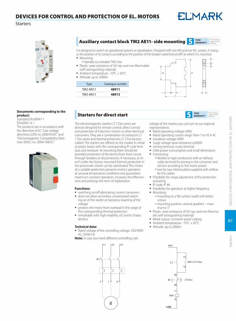
81
DEV
ICES
FO
R CO
NTR
OL
AN
D P
ROTE
CTI
ON
OF
EL. M
OTO
RSSt
arte
rs
DEVICES FOR CONTROL AND PROTECTION OF EL. MOTORSStarters
Auxiliary contact block TM2 AE11- side mounting*for industrial usage, 3 years warranty5 YEAR
WARRANTY
It is designed to switch on operational systems or signalization. Designed with one NO and one NC contact. It chang-es the position of its contacts according to the position of the breaker (switched on/off) to which it is mounted.
� Mounting: à laterally to a breaker TM2-Exx
� Plastic: wear resistance of UV rays and non-flammable (self-extinguishing material)
� Ambient temperature: -10°C + 65°C � Altitude: up to 2000m
Type Catalogue number
ТМ2 АN11 48911ТМ3 АN11 48913
Starters for direct start*for industrial usage, 3 years warranty5 YEAR
WARRANTY
The electromagnetic starters LT 5 Dxx series are devices designed for remote control, direct control and protection of induction motors or other electrical consumers. They are a combination of contactors LT 1 Dxx series and thermal protection LT 2 Exx factory cabled. The starters are offered on the market in metal or plastic boxes with the corresponding IP code from dust and moisture. At mounting there should be provided protection of the device from short circuit through breakers or disconnectors. If necessary, at cli-ent’s order the factory mounted thermal protection in the pneumatic starter can be substituted. The choice of a suitable protection prevents motor’s operation at unusual temperature conditions and guarantees maximum constant operation, increases the effective-ness and prolongs the term of exploitation.
Functions: � switching on/off alternating current consumers � does not allow secondary unwarranted switch-
ing on of the starter at transitory lowering of the voltage
� protects the motor from overload in the range of the corresponding thermal protection
� remarkable with high reliability of current charac-teristics
Technical data: � Rated voltage of the controlling voltage: 230/400V
AC; 50/60 HzNote: In case you need different controlling coils
voltage of the starters you can turn to our regional representatives.
� Rated operating voltage: 690V � Rated operating current range: from 7 to 93 A AC � insulation voltage: 690V � Surge voltage wear resistance:≥6000V � Joining terminal: screw terminal � Little power consumption and small dimensions � Connecting:
à flexible or rigid conductors with or without cable terminal for joining to the consumer and section according to the motor power
à two by two inlets/outlets supplied with orifices for the cables
� Possibility for range adjustment of the protection activating
� IP code: IP 44 � Possibility for operation at higher frequency � Mounting:
à mounting to a flat surface (wall) with bolts/screws
à mounting position: vertical gradient – maxi-mum± 5°
� Plastic: wear resistance of UV rays and non-flamma-ble (self-extinguishing material)
� Metal corpus: corrosion-proof coating � Ambient temperature: -10°C + 65°C � Altitude: up to 2000m
Documents corresponding to the product:Standard EN 60947-1EN 60947-4-1The products are in accordance with the directives of EC “Low voltage directives (LVD) no 2006/95/EC” and “Electromagnetic Compatibility Direc-tives (EMC) no. 2004/108/EC”.

82
DEV
ICES
FO
R CO
NTR
OL
AN
D P
ROTE
CTI
ON
OF
EL. M
OTO
RS
DEVICES FOR CONTROL AND PROTECTION OF EL. MOTORSStarters
Star
ters
Type
Rated capacity of motors 50/60Hz AC-3 category Rated
current (A)
Thermal relay adjust-ment range
Coil voltage
(V)
Packing/Box (pcs)
Cataloguenumber
220V230V
380V400V
415V440V
LT5 D093 2.2 4.0 4.0 9 7 .. 10A230 1 / 16 43091
400 1 / 16 43092
LT5 D123 3.0 5.5 5.5 12 9 .. 13A230 1 / 16 43121
4.0 1 / 16 43122
LT5 D185 4.0 7.5 9.0 18 12 .. 18A230 1 / 16 43181
400 1 / 16 43182
Note: Upon request the thermal relay will be replaced166
140
120
2 x PE13
2x
PE
13
2x
5.5
�
150
88
Type
Rated capacity of motors 50/60Hz AC-3 category Rated
current (A)
Thermal relay adjust-ment range
Coil voltage
(V)
Packing/Box (pcs)
Cataloguenumber
220V230V
380V400V
415V440V
LT5 D255 5.5 11 11 25 17 .. 25A230 1 / 16 43251
400 1 / 16 43252
LT5 D325 7.5 15 15 32 23 .. 32A230 1 / 16 43321
400 1 / 16 43322
Note: Upon request the thermal relay will be replaced
142
135
185
2 x PE16
165
101
16
2x
5.5
�P
E13
Type
Rated capacity of motors 50/60Hz AC-3 category Rated
current (A)
Thermal relay adjust-ment range
Coil voltage
(V)
Packing/Box (pcs)
Cataloguenumber
220V230V
380V400V
415V440V
LT5 D405 11.0 18.5 22 40 30 .. 40A230 1/6 43401
400 1/6 43402
LT5 D655 18.5 30.0 37 65 48 .. 65A230 1/6 43651
400 1/6 43652
LT5 D955 25.0 45.0 45 95 80 .. 93A230 1/6 43951
400 1/6 43952
Note: Upon request the thermal relay will be replaced
312
150
161
2 x PE29
195PE13
181
105
4x
7.7
�
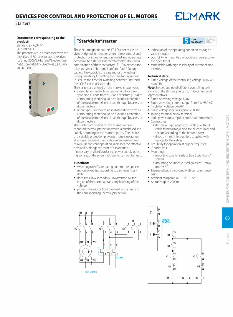
83
DEV
ICES
FO
R CO
NTR
OL
AN
D P
ROTE
CTI
ON
OF
EL. M
OTO
RSSt
arte
rs
DEVICES FOR CONTROL AND PROTECTION OF EL. MOTORSStarters
”Star/delta”starter*for industrial usage, 3 years warranty5 YEAR
WARRANTY
The electromagnetic starters LT 3 Dxx series are de-vices designed for remote control, direct control and protection of induction motors coiled and operating according to a starter scheme “star/delta”. They are a combination of three contactors LT 1 Dxx series, time relay and a set of buttons “start” and “stop” factory cabled. They provide the easy motor unwinding giving possibility for setting the time for unwinding in “star” as the time for switching between “star” and “delta” is fixed to 0.5 seconds.The starters are offered on the market in two types:
� closed type – metal boxes providing the corre-sponding IP code from dust and moisture (IP 54) as at mounting there should be provided protection of the device from short circuit through breakers or disconnectors
� open type – for mounting in distribution boxes as at mounting there should be provided protection of the device from short circuit through breakers or disconnectors
The starters are offered on the market without mounted thermal protection which is purchased sep-arately according to the motor capacity. The choice of a suitable protection prevents motor’s operation at unusual temperature conditions and guarantees maximum constant operation, increases the effective-ness and prolongs the term of exploitation.If necessary, at client’s order the power supply operat-ing voltage of the pneumatic starter can be changed.
Functions: � switching on/off alternating current three phase
motors operating according to a scheme “star - delta”
� does not allow secondary unwarranted switch-ing on of the starter at transitory lowering of the voltage
� protects the motor from overload in the range of the corresponding thermal protection
� indication of the operating condition through a valve indicator
� possibility for mounting of additional contacts (for the open type)
� remarkable with high reliability of current charac-teristics
Technical data: � Rated voltage of the controlling voltage: 400V AC;
50/60 HzNote: In case you need different controlling coils voltage of the starters you can turn to our regional representatives.
� Rated operating voltage: 690V � Rated operating current range: from 7 to 93A AC � insulation voltage: >690V � Surge voltage wear resistance:≥6000V � Joining terminal: screw terminal � Little power consumption and small dimensions � Connecting:
à flexible or rigid conductors with or without cable terminal for joining to the consumer and section according to the motor power
à three by three inlets/outlets supplied with orifices for the cables
� Possibility for operation at higher frequency � IP code: IP54 � Mounting:
à mounting to a flat surface (wall) with bolts/screws
à mounting position: vertical gradient – maxi-mum± 5°
� The metal body is covered with corrosion-proof paint
� Ambient temperature: -10°C + 65°C � Altitude: up to 2000m
Documents corresponding to the product:Standard EN 60947-1EN 60947-4-1The products are in accordance with the directives of EC “Low voltage directives (LVD) no 2006/95/EC” and “Electromag-netic Compatibility Directives (EMC) no. 2004/108/EC”.
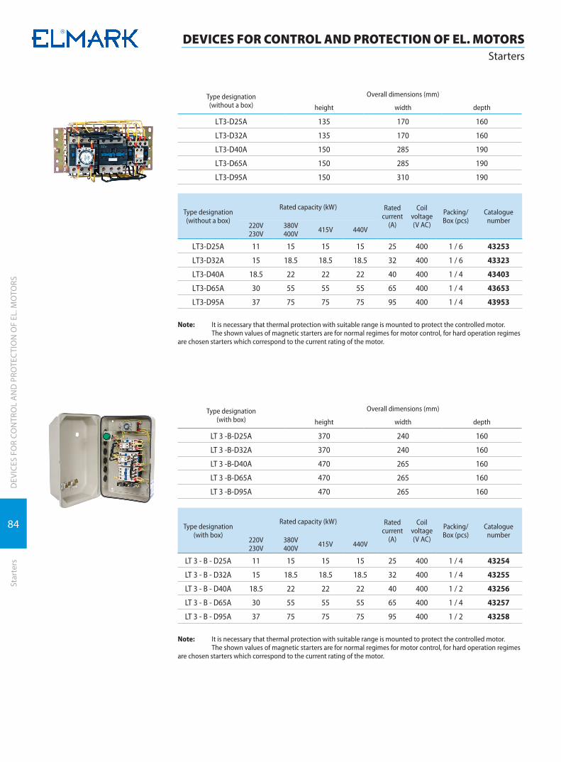
84
DEV
ICES
FO
R CO
NTR
OL
AN
D P
ROTE
CTI
ON
OF
EL. M
OTO
RS
DEVICES FOR CONTROL AND PROTECTION OF EL. MOTORSStarters
Star
ters
Type designation(without a box)
Overall dimensions (mm)
height width depth
LТ3-D25А 135 170 160
LТ3-D32А 135 170 160
LТ3-D40А 150 285 190
LТ3-D65А 150 285 190
LТ3-D95А 150 310 190
Type designation(without a box)
Rated capacity (kW) Rated current
(A)
Coil voltage (V AC)
Packing/Box (pcs)
Cataloguenumber
220V230V
380V400V 415V 440V
LТ3-D25А 11 15 15 15 25 400 1 / 6 43253
LТ3-D32А 15 18.5 18.5 18.5 32 400 1 / 6 43323
LТ3-D40А 18.5 22 22 22 40 400 1 / 4 43403
LТ3-D65А 30 55 55 55 65 400 1 / 4 43653
LТ3-D95А 37 75 75 75 95 400 1 / 4 43953
Note: It is necessary that thermal protection with suitable range is mounted to protect the controlled motor. The shown values of magnetic starters are for normal regimes for motor control, for hard operation regimes are chosen starters which correspond to the current rating of the motor.
Type designation(with box)
Overall dimensions (mm)
height width depth
LT 3 -B-D25A 370 240 160
LT 3 -B-D32A 370 240 160
LT 3 -B-D40A 470 265 160
LT 3 -B-D65A 470 265 160
LT 3 -B-D95A 470 265 160
Type designation(with box)
Rated capacity (kW) Rated current
(A)
Coil voltage (V AC)
Packing/Box (pcs)
Cataloguenumber
220V230V
380V400V 415V 440V
LT 3 - B - D25А 11 15 15 15 25 400 1 / 4 43254
LT 3 - B - D32А 15 18.5 18.5 18.5 32 400 1 / 4 43255
LT 3 - B - D40А 18.5 22 22 22 40 400 1 / 2 43256
LT 3 - B - D65А 30 55 55 55 65 400 1 / 4 43257
LT 3 - B - D95А 37 75 75 75 95 400 1 / 2 43258
Note: It is necessary that thermal protection with suitable range is mounted to protect the controlled motor. The shown values of magnetic starters are for normal regimes for motor control, for hard operation regimes are chosen starters which correspond to the current rating of the motor.

85
DEV
ICES
FO
R CO
NTR
OL
AN
D P
ROTE
CTI
ON
OF
EL. M
OTO
RSSt
arte
rs
DEVICES FOR CONTROL AND PROTECTION OF EL. MOTORSStarters
Reverse starter*for industrial usage, 3 years warranty5 YEAR
WARRANTY
The electromagnetic starters LT4 Dxx series are de-vices used for direct start, reverse start and protection of induction motors with short connected rotor. They are a combination of two contactors LT1 Dxx series supplied with two buttons “start” and one “stop” fac-tory cabled. They provide the unwinding of the motor in one of the directions with possibility for pushing the button “stop” and giving command from the other “start” for changing the motor winding direction. The two contactors are mechanically blocked and do not allow simultaneous start in both winding directions. The starters are offered – closed type in metal boxes providing the corresponding IP code from dust and moisture (IP54) as at mounting there should be provided protection of the device from short circuit through breakers or disconnectors. The starters are of-fered with mounted thermal protection which can be substituted according to the motor power. The choice of a suitable protection prevents motor’s operation at unusual temperature conditions and guarantees maximum constant operation, increases the effective-ness and prolongs the term of exploitation.If necessary, at order the power supply operating volt-age of the pneumatic starter can be changed.
Functions: � switching on alternating current three phase mo-
tors in one winding direction, switching off and change of the winding direction at giving a signal
� does not allow secondary unwarranted switch-ing on of the starter at transitory lowering of the voltage
� protects the motor from overload in the range of the corresponding thermal protection
� remarkable with high reliability of current charac-teristics
Technical data: � Rated voltage of the controlling voltage: 400V AC;
50/60 HzNote: In case you need different controlling coils voltage of the starters you can turn to our regional representatives.
� Rated operating voltage: 690V � Rated operating current range: from 7 to 93 A AC � insulation voltage: 690V � Surge voltage wear resistance:≥6000V � Joining terminal: screw terminal � Little power consumption and small dimensions � Connecting:
à flexible or rigid conductors with or without cable terminal for joining to the consumer and section according to the motor power
à three by three inlets/outlets supplied with orifices for the cables
� Possibility for operation at higher frequency � IP code: IP 44 � Mounting:
à mounting to a flat surface (wall) with bolts/screws
à mounting position: vertical gradient – maxi-mum± 5°
� The metal body is covered with corrosion-proof paint
� Ambient temperature: -10°C + 65°C � Altitude: up to 2000m
Documents corresponding to the product:Standard EN 60947-1EN 60947-4-1The products are in accordance with the directives of EC “Low voltage directives (LVD) no 2006/95/EC” and “Electromag-netic Compatibility Directives (EMC) no. 2004/108/EC”.
scheme “Reverse”
Type designation(with a box)
Rated capacity (kW) Overall dimensions (mm) Rated current
(A)
Coil voltage (V AC)
Packing/Box (pcs)
Cataloguenumber220V
230V380V400V 415V 440V height width depth
LT 4 - B - D25А 11.0 15.0 15.0 15.0 240 240 160 25 400 1 / 8 43001
LT 4 - B - D32А 15.0 18.5 18.5 18.5 240 240 160 32 400 1 / 4 43002
LT 4 - B - D40А 18.5 22.0 22.0 22.0 270 265 160 40 400 1 / 2 43003
LT 4 - B - D65А 30.0 55.0 55.0 55.0 270 265 160 65 400 1 / 4 43004
LT 4 - B - D95А 37.0 75.0 75.0 75.0 270 265 160 95 400 1 / 4 43005
LT 4 - B - D25А 11.0 15.0 15.0 15.0 240 240 160 25 230 1 / 4 43006
LT 4 - B - D32А 15.0 18.5 18.5 18.5 240 240 160 32 230 1 / 4 43007
LT 4 - B - D40А 18.5 22.0 22.0 22.0 270 265 160 40 230 1 / 4 43008
LT 4 - B - D65А 30.0 55.0 55.0 55.0 270 265 160 65 230 1 / 4 43009
LT 4 - B - D95А 37.0 75.0 75.0 75.0 270 265 160 95 230 1 / 4 43010

86
DEV
ICES
FO
R CO
NTR
OL
AN
D P
ROTE
CTI
ON
OF
EL. M
OTO
RS
DEVICES FOR CONTROL AND PROTECTION OF EL. MOTORSFrequency inverters
Freq
uenc
y in
vert
ers
Type of signELМ1000- G -0150 T3 С
lid type code: C=metal clips; B=plastic lidpower supply code: T3=three-phase; S2= single phasemotor powerinverter type: G=constant momentuminverter model
TypeOverall dimensions (mm)
H W A B D d
ELМ1000-G0007S2B 150 105 139 94 120 Ø4ELМ1000-G0015S2B 170 125 160 114 140 Ø5ELM1000-G0022S2B 170 125 160 114 140 Ø5ELМ1000-G0007T3B 170 125 160 114 140 Ø5ELМ1000-G0015T3B 170 125 160 114 140 Ø5ELМ1000-G0022T3B 170 125 160 114 140 Ø5ELМ1000-G0037T3B 250 162 233 145 150 Ø6ELМ1000-G0040T3B 250 162 233 145 150 Ø6ELМ1000-G0055T3B 300 200 282 182 160 Ø6ELМ1000-G0075T3B 300 200 282 182 160 Ø6ELМ1000-G0110T3C 340 225 322 160 220 Ø6ELМ1000-G0150T3C 380 230 362 186 225 Ø6
Documents corresponding to the product:Standard EN60898-1EN 60947-2The products are in accordance with the directives of EC “Low voltage directives (LVD) no 2006/95/EC” and “Electromag-netic Compatibility Directives (EMC) no. 2004/108/EC”.
ELM 1000 frequency inverters 3 YEAR WARRANTY
Frequency inverters are designed to control three-phase induction motors with short-circuited rotor. They provide for the implementation of some control laws, thus becoming an indispensable part of the control systems for conveyors and packaging machines, pumps, air conditioning systems, etc. The ELM 1000 inverter provides the so-called no-sensor control, V/f control and impulse control while the out-put load can reach up to 150% within 60 seconds. It features easy definition of curves and easy parameters setting of inverter through the use of control panel buttons. The inverter can auto calibrate according to the motor power, i.e. if the inverter is connected to a motor with power different from that set by the inverter manufacturer, it automatically adjusts its pro-grammable parameters to suit the motor parameters.
Functions: � rotation speed increase – automatic and manual � sliding compensation: from 0 to 20% � no-sensor control of the motor � adjustment of the V/F control curve – linear or
quadratic � energy saving through automatic optimization of
the V/F curve � PID control law implementation option � omission of resonance frequencies � JOG function � ‘counter’ function � automatic restart option in case of power supply
failure � fifteen speed degrees control option � control choice from the control panel; external or
COM terminal � frequency control from the control panel, external
potentiometer by current or by voltage � auto-calibration in accordance with the switched
motor � incoming signals on clockwise or counter-clock-
wise rotation, multi-step control, restart, etc. � outgoing discrete control signal 24V � outgoing analogue control signal 0 – 10V � DC brake in static mode � dynamic breaking with external breaking resistor –
used in inert electric motor load � output voltage adjustment option � activation of output safety functions option � electronic motor protection
Technical features: � Rated working voltage: 230/400V АС; 50 Hz � Permissible working voltage deviation: ±10% � Unbalance of phases: < 3% � Frequency fluctuation: < 5% � Output frequency: 0 – 400 Hz � Output voltage: from 0 to Ubx max � Overload capacity:
à constant: up to 110% à momentary: up to 150%
� Precision of output frequency adjustment: 0.1% � Type of connection:
à the connection of the inverter to the power supply should always be done through a circuit breaker of the MCB or MCCB type
à connection of consumer to power terminals: through conductors suitable for the power
à connection of control circuits: flexible conduc-tor up to 1.5 mm2
Note: It is not recommendable to mount contac-tors or other commutation devices between the frequency inverter and the motor, except as described in the product passport.
� Mounting: à mounting to a flat surface by means of bolts à mounting position – vertical gradient maxi-mum ± 5°
Note: When more than one inverter is mounted in a board, it is recommendable to mount them side by side and when this is not possible, the appropriate cooling conditions should be provided.
� Plastic: UV-rays resistant and fire resistant (self-extinguishing material)
� Ambient temperature: -10° to 65° C � Altitude : up to 2000 m � Function enhancement option: through the inclu-
sion of additional modules

87
DEV
ICES
FO
R CO
NTR
OL
AN
D P
ROTE
CTI
ON
OF
EL. M
OTO
RSSo
ft s
tart
er
DEVICES FOR CONTROL AND PROTECTION OF EL. MOTORSSoft starter
Type Input voltage (V)
Maximum output power
(kW)
Maximum current
output (А)
Packing/Box (pcs)
Cataloguenumber
ELМ1000-G0007S2B 230 0.75 4.5 1 / 4 423107MELМ1000-G0015S2B 230 1.5 7 1 / 4 423115MELM1000-G0022S2B 230 2.2 9 1 / 4 423122MELМ1000-G0007T3B 400 0.75 2 1 / 4 423307MELМ1000-G0015T3B 400 1.5 4 1 / 4 423315MELМ1000-G0022T3B 400 2.2 6.5 1 / 4 423322MELМ1000-G0037T3B 400 3.7 8 1 / 1 423337MELМ1000-G0040T3B 400 4.0 9 1 / 1 423340MELМ1000-G0055T3B 400 5.5 12 1 / 1 423355MELМ1000-G0075T3B 400 7.5 17 1 / 1 423375MELМ1000-G0110T3C 400 11 23 1 / 1 423391MELМ1000-G0150T3C 400 15 32 1 / 1 423392M
Documents corresponding to the product:Standard EN60947-4-2EN 60947-1The products are in accordance with the directives of EC “Low voltage directives (LVD) no 2006/95/EC” and “Electromag-netic Compatibility Directives (EMC) no. 2004/108/EC”.
Soft starter ELM 2500 3 YEAR WARRANTY
Soft starters are designed to control the start of three-phase induction motors with short-circuited rotor. A number of motor control issues are avoided through them, and namely: prolonged start moments, auto-ignition of motor, there is no need of stardelta switch-ing, auto-transformer switching, resistant switching, etc. The ELM 2500 soft starter pertains to the AC53b type of starters as per the standard requirements and it provides rotation of motor and once the opera-tion mode is set, a shunt contactor of the LT 1 D/F series is switched to control motor operation as the soft starter is not designed to control motors in a set mode. Under a stop command in accordance with the selected control scheme, the soft starter can or can not be included in shutting the motor down.
Functions: � System functions
à over-voltage protection – motor will switch off when power supply exceeds the preset limits
à overload protection – protects the motor from overloading
à phase loss protection à temperature overload protection
� Control functions
à output faults à motor faults diagnostics à keyboard or outward control à delayed start option à faults memory
Technical features: � Rated working voltage: 230/400V АС; 50 Hz � Permissible working voltage deviation: ±10% � Unbalance of phases: < 3% � Frequency fluctuation: < 5% � Obligatory bypass contactor installation � Mounting :
à mounting to a flat surface through bolts à mounting position – vertical gradient maxi-mum ± 5°
Note: When more than one soft starter is mounted in a board, it is recommendable to mount them side by side and when this is not possible, the appropriate cooling conditions should be provided.
� Plastic: UV-rays resistant and fire resistant (self-extinguishing material)
� Altitude : up to 2000 m
TypeOverall dimensions (mm)
A B C E F d
EL M25015 250 153 162 219 140 Ø6
EL M25022 250 153 162 219 140 Ø6
EL M25037 250 153 162 219 140 Ø6
EL M25045 250 153 162 219 140 Ø6
EL M25055 250 153 162 219 140 Ø6
EL M25075 510 260 194 389 232 Ø8
Type Power of mo-tor (kW)
Rated current (A)
Type of bypass
contactor
Section of power supply
conductors
Packing/Box (pcs)
Cataloguenumber
EL M25015 15 30 LT 1-D 50 10 1 / 1 42225015EL M25022 22 45 LT 1-D 50 10 1 / 1 42225022EL M25037 37 76 LT 1-D 80 16 1 / 1 42225037EL M25045 45 90 LT 1-D 95 25 1 / 1 42225045EL M25055 55 110 LT 1-F 115 25 1 / 1 42225055EL M25075 75 150 LT 1-F 150 35 1 / 1 42225075

CAPACITYCOEFFICIENT COMPENSATION
CAPACITY COEFFICIENT COMPENSATION
COEFFICIENT COMPENSATION
Complex compensating devices | 90
Capacitor batteries for reactive energy compensation | 91
Cosφ regulator | 91

90
CAPACITY COEFFICIENT COMPENSATION Complex compensating devices
CA
PACI
TY C
OEF
FICI
ENT
COM
PEN
SATI
ON
Co
mpl
ex c
ompe
nsat
ing
devi
ces
Complex compensating devices 3 YEAR WARRANTY
The use of electrical energy in industry is invariably connected with its transformation. The development of semiconductor elements and the broader coming of semi-conductor transformers, frequency control, welding machines and electrical arc furnaces in industrial projects have a negative impact over the electrical power quality in the electro distributing systems. Induction machines need reactive energy to create electromagnetic field. The reactive compo-nent of current is taken from the electro distributing systems but it leads to additional losses in the power supply system and makes shorter the exploitation term of electrical devices. This leads to curving of the sinusoid form of current and voltage and interfer-ences with harmonic character. Compensating the reactive power means to fill up the system in such a way that the needed reactive power to be created from the compensating device instead of being taken from the electro transportation system. This leads to killing the voltage fall and cable losses and increasing the outlet power of the power transporters and cutting down the bills for overconsumption of reactive energy paid by consumers to the electric-ity supply company. In practice compensating the reactive energy and high harmonics through LC filters combined in compensating installations has the broadest spreading.
There are several types of compensation ac-cording to their location:
� individual compensation – when to every single motor or consumer is mounted a compensating system. It is applied to powerful motors and trans-formers with fixed capacity.
� installation compensation – when the consumers from the whole section (workshop) are grouped and compensation is accomplished for the whole section.
� overall compensation – accomplished at full com-pensation in the inlet of the installation.
According to the type of the compensating devices compensation can be:
� passive – when the system supplies constant reac-tive power. In this case the system does not react to changes in the size and nature of the harmonic components and also to the per cent increase of the reactive energy in time.
� active – broader spread. The system controls the form of the consumed current and generates dif-ferent capacity depending on the load changes.
When designing the electro distributing system of industrial projects the following tasks are taken into consideration:
� defining the factor of non-sinusoid of the consum-ers and the voltage harmonic components
� defining the additional loading of the capacitor batteries from the harmonic components and calculating the filtering elements if needed
The calculation of the compensating device capacity is done by reading the reactive energy of the system and the working time of the system. Compensating devices represent a device of one or several metal boxes with common rail system, automatic regulator for cosφ control RPSF-xx series, different number of capacitor batteries (according to the capacity of the device) with different capacity HY 111 series, contac-tors for capacitor batteries control CJ 19-43 series, protective elements, etc.
The broadest spreading of compensation has ac-quired the compensation of harmonics and reactive energy with capacitors for high voltage. Capacitors HY 111 series are voltage remeasured and are able to en-dure overload from harmonic components up to 7% from the basic harmonics. They are used in systems with high harmonics foul up to 25%.
The high harmonics composition is defined after measuring the influence rate of each separate har-monics compared to the first one. In Bulgaria mostly spread are 5, 7, 9, 11 and 13 harmonics. The capacitors are remeasured for voltage 415V and are normally mounted right in the compensation systems.
When the high harmonics are over 25% the system is taken to be foul and in this case except using capaci-tors, filters for leveling the harmonics are to be used as well. These filters are calculated on the basis of the corresponding voltage harmonics and differ for the different harmonics. They are calculated using com-plex mathematical programme which reads the foul rate, the significance per cent of the voltage harmonic component, etc.
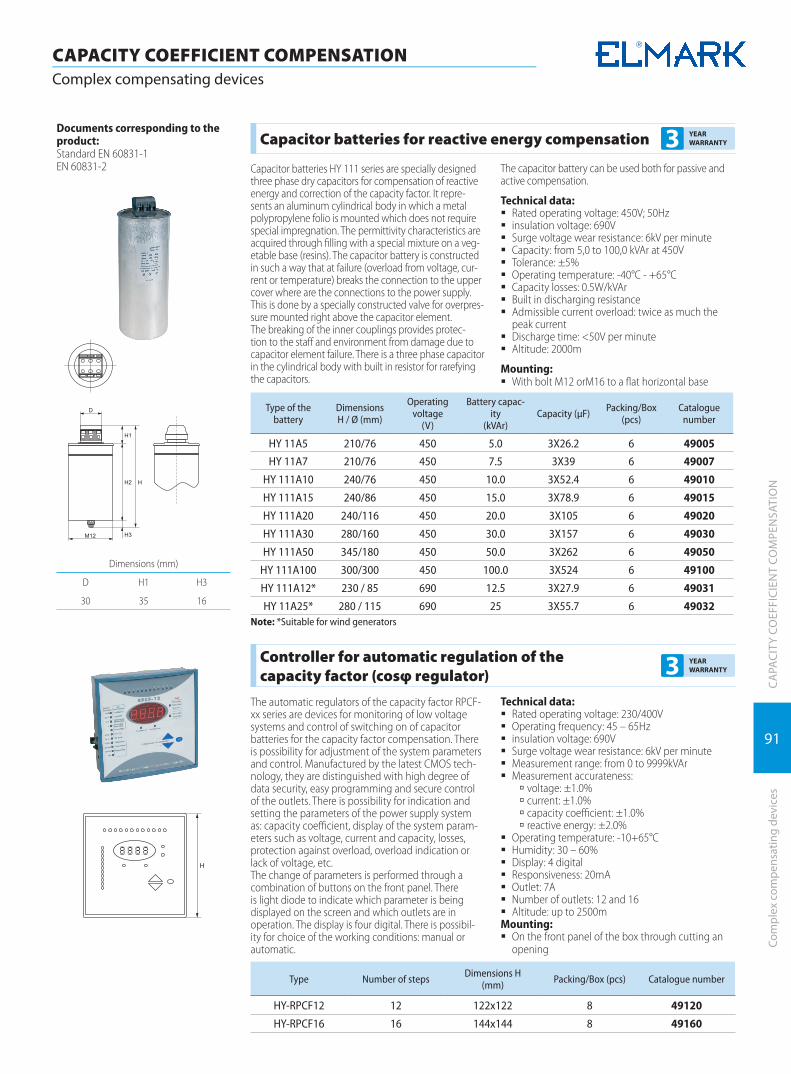
91
CAPACITY COEFFICIENT COMPENSATION Complex compensating devices
CA
PACI
TY C
OEF
FICI
ENT
COM
PEN
SATI
ON
Co
mpl
ex c
ompe
nsat
ing
devi
ces
Dimensions (mm)
D H1 H3
30 35 16
Documents corresponding to the product:Standard EN 60831-1EN 60831-2
Capacitor batteries for reactive energy compensation 3 YEAR WARRANTY
Capacitor batteries HY 111 series are specially designed three phase dry capacitors for compensation of reactive energy and correction of the capacity factor. It repre-sents an aluminum cylindrical body in which a metal polypropylene folio is mounted which does not require special impregnation. The permittivity characteristics are acquired through filling with a special mixture on a veg-etable base (resins). The capacitor battery is constructed in such a way that at failure (overload from voltage, cur-rent or temperature) breaks the connection to the upper cover where are the connections to the power supply. This is done by a specially constructed valve for overpres-sure mounted right above the capacitor element. The breaking of the inner couplings provides protec-tion to the staff and environment from damage due to capacitor element failure. There is a three phase capacitor in the cylindrical body with built in resistor for rarefying the capacitors.
The capacitor battery can be used both for passive and active compensation.
Technical data: � Rated operating voltage: 450V; 50Hz � insulation voltage: 690V � Surge voltage wear resistance: 6kV per minute � Capacity: from 5,0 to 100,0 kVAr at 450V � Tolerance: ±5% � Operating temperature: -40°C - +65°C � Capacity losses: 0.5W/kVAr � Built in discharging resistance � Admissible current overload: twice as much the
peak current � Discharge time: <50V per minute � Altitude: 2000m
Mounting: � With bolt M12 orM16 to a flat horizontal base
Type of the battery
Dimensions H / Ø (mm)
Operating voltage
(V)
Battery capac-ity
(kVAr)Capacity (µF) Packing/Box
(pcs)Catalogue
number
HY 11A5 210/76 450 5.0 3X26.2 6 49005
HY 11A7 210/76 450 7.5 3X39 6 49007
HY 111A10 240/76 450 10.0 3X52.4 6 49010
HY 111A15 240/86 450 15.0 3X78.9 6 49015
HY 111A20 240/116 450 20.0 3X10⁵ 6 49020
HY 111A30 280/160 450 30.0 3X157 6 49030
HY 111A50 345/180 450 50.0 3X262 6 49050
HY 111A100 300/300 450 100.0 3X524 6 49100
HY 111A12* 230 / 85 690 12.5 3X27.9 6 49031
HY 11A25* 280 / 115 690 25 3X55.7 6 49032Note: *Suitable for wind generators
Controller for automatic regulation of the capacity factor (cosφ regulator) 3 YEAR
WARRANTY
The automatic regulators of the capacity factor RPCF-xx series are devices for monitoring of low voltage systems and control of switching on of capacitor batteries for the capacity factor compensation. There is possibility for adjustment of the system parameters and control. Manufactured by the latest CMOS tech-nology, they are distinguished with high degree of data security, easy programming and secure control of the outlets. There is possibility for indication and setting the parameters of the power supply system as: capacity coefficient, display of the system param-eters such as voltage, current and capacity, losses, protection against overload, overload indication or lack of voltage, etc.The change of parameters is performed through a combination of buttons on the front panel. There is light diode to indicate which parameter is being displayed on the screen and which outlets are in operation. The display is four digital. There is possibil-ity for choice of the working conditions: manual or automatic.
Technical data: � Rated operating voltage: 230/400V � Operating frequency: 45 – 65Hz � insulation voltage: 690V � Surge voltage wear resistance: 6kV per minute � Measurement range: from 0 to 9999kVAr � Measurement accurateness:
à voltage: ±1.0% à current: ±1.0% à capacity coefficient: ±1.0% à reactive energy: ±2.0%
� Operating temperature: -10+65°C � Humidity: 30 – 60% � Display: 4 digital � Responsiveness: 20mA � Outlet: 7A � Number of outlets: 12 and 16 � Altitude: up to 2500m
Mounting: � Оn the front panel of the box through cutting an
opening
Type Number of steps Dimensions H (mm) Packing/Box (pcs) Catalogue number
HY-RPCF12 12 122x122 8 49120
HY-RPCF16 16 144x144 8 49160
TIMERS, RELAYSAND DISPLAYING DEVICES
TIMERS, RELAYS AND DISPLAYING DEVICES
Programmable timers | 94
Digital counters | 99
Industrial relays | 101
Current measurement transformers | 103
Voltage transformers | 105
Displaying measurement devices | 107
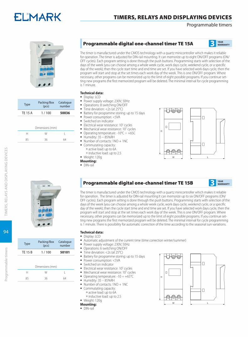
94
TIM
ERS,
REL
AYS
AN
D D
ISPL
AYIN
G D
EVIC
ES
TIMERS, RELAYS AND DISPLAYING DEVICESProgrammable timers
Prog
ram
mab
le ti
mer
s
Dimensions (mm)
H W L
85 36 64
Programmable digital one-channel timer TE 15A 3 YEAR WARRANTY
The timer is manufactured under the CMOS technology with a quartz minicontroller which makes it reliable for operation. The timer is adjusted for DIN-rail mounting. It can memorize up to eight ON/OFF programs (ON/OFF cycles). Each program setting is done through the push buttons. Programming starts with selection of the days of the week (you can choose among a whole week cycle, work days cycle, weekend cycle, or a specific day of the week); then the cycle start time and end time are set. If you have selected work days cycle, then the program will start and stop at the set times each work day of the week. This is one ON/OFF program. Where necessary, other programs can be memorized up to the limit of eight possible programs. If you continue set-ting new programs the first memorized program will be deleted. The minimal interval for cycle programming is 1 minute.
Technical data: � Display: LCD � Power supply voltage: 230V; 50Hz � Operations: 8 switching ON/OFF � Time deviation: <2s (at 25°C) � Battery for programme storing: up to 15 days � Power consumption: <5VA � Switched on indicator � Electrical wear resistance: 105 cycles � Mechanical wear resistance: 107 cycles � Operating temperature: -10°C ÷ +65C � Humidity: 35 – 85%RH � Number of contacts: 1NO + 1NC � Commutating capacity:
à active load: up to 6A à inductive load: up to 2.5
� Weight: 120gMounting:
� DIN-rail
Type Packing/Box (pcs)
Cataloguenumber
ТЕ 15 А 1 / 100 50036
Dimensions (mm)
H W L
85 36 64
Programmable digital one-channel timer TE 15B 3 YEAR WARRANTY
The timer is manufactured under the CMOS technology with a quartz minicontroller which makes it reliable for operation. The timer is adjusted for DIN-rail mounting.It can memorize up to six ON/OFF programs (ON/OFF cycles). Each program setting is done through the push buttons. Programming starts with selection of the days of the week (you can choose among a whole week cycle, work days cycle, weekend cycle, or a specific day of the week); then the cycle start time and end time are set. If you have selected work days cycle, then the program will start and stop at the set times each work day of the week. This is one ON/OFF program. Where necessary, other programs can be memorized up to the limit of eight possible programs. If you continue set-ting new programs the first memorized program will be deleted. The minimal interval for cycle programming is 1 minute. There is possibility for automatic correction of the time according to the seasonal sun variations.
Technical data: � Display: LCD � Automatic adjustment of the current time (time correction winter/summer) � Power supply voltage: 230V; 50Hz � Operations: 6 switching ON/OFF � Time deviation: <2s (at 25°C) � Battery for programme storing: up to 15 days � Power consumption: <5VA � Switched on indicator � Electrical wear resistance: 105 cycles � Mechanical wear resistance: 107 cycles � Operating temperature: -10 ÷ +65°C � Humidity: 35 – 85%RH � Number of contacts: 1NO + 1NC � Commutating capacity:
à active load: up to 6A à inductive load: up to 2.5
� Weight: 120gMounting:
� DIN-rail
Type Packing/Box (pcs)
Cataloguenumber
ТЕ 15 B 1 / 100 50101
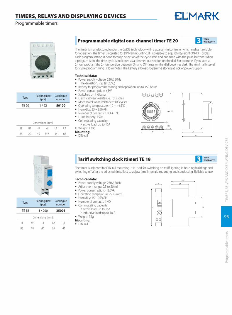
95
TIM
ERS,
REL
AYS
AN
D D
ISPL
AYIN
G D
EVIC
ESPr
ogra
mm
able
tim
ers
TIMERS, RELAYS AND DISPLAYING DEVICESProgrammable timers
Dimensions (mm)
H H1 H2 W L1 L2
85 20 45 54.5 34 66
Programmable digital one-channel timer TE 20 3 YEAR WARRANTY
The timer is manufactured under the CMOS technology with a quartz minicontroller which makes it reliable for operation. The timer is adjusted for DIN-rail mounting. It is possible to adjust forty-eight ON/OFF cycles. Each program setting is done through selection of the cycle start and end time with the push buttons. When a program is on, the time cycle is indicated as a dimmed out section on the dial. For example, if you start a 2-hour program the 2-hour portion between On and Off times on the dial becomes dark. The minimal interval for cycle programming is 15 minutes. The battery allows programme storing at lack of power supply.
Technical data: � Power supply voltage: 230V; 50Hz � Time deviation: <2s (at 25°C) � Battery for programme storing and operation: up to 150 hours � Power consumption: <5VA � Switched on indicator � Electrical wear resistance: 105 cycles � Mechanical wear resistance: 107 cycles � Operating temperature: -10 ÷ +65°C � Humidity: 35 – 85%RH � Number of contacts: 1NO + 1NC � Li-Ion battery: 150h � Commutating capacity:
à active load: up to 16A � Weight: 120g
Mounting: � DIN-rail
Type Packing/Box (pcs)
Cataloguenumber
TE 20 1 / 92 50100
Dimensions (mm)
H W L1 L2 D
82 18 40 65 45
Tariff switching clock (timer) TE 18 3 YEAR WARRANTY
The timer is adjusted for DIN-rail mounting. It is used for switching on tariff lighting in housing buildings and switching off after the adjusted time. Easy to adjust time intervals, mounting and conducting. Reliable to use.
Technical data: � Power supply voltage: 230V; 50Hz � Adjustment range: 0.5 to 20 min � Power consumption: <2.5VA � Operating temperature: -5 ÷ +65°C � Humidity: 45 – 95%RH � Number of contacts: 1NO � Commutating capacity:
à active load: up to 16A à inductive load: up to 10 A
� Weight: 75gMounting:
� DIN-rail
Type Packing/Box (pcs)
Cataloguenumber
TE 18 1 / 200 35005
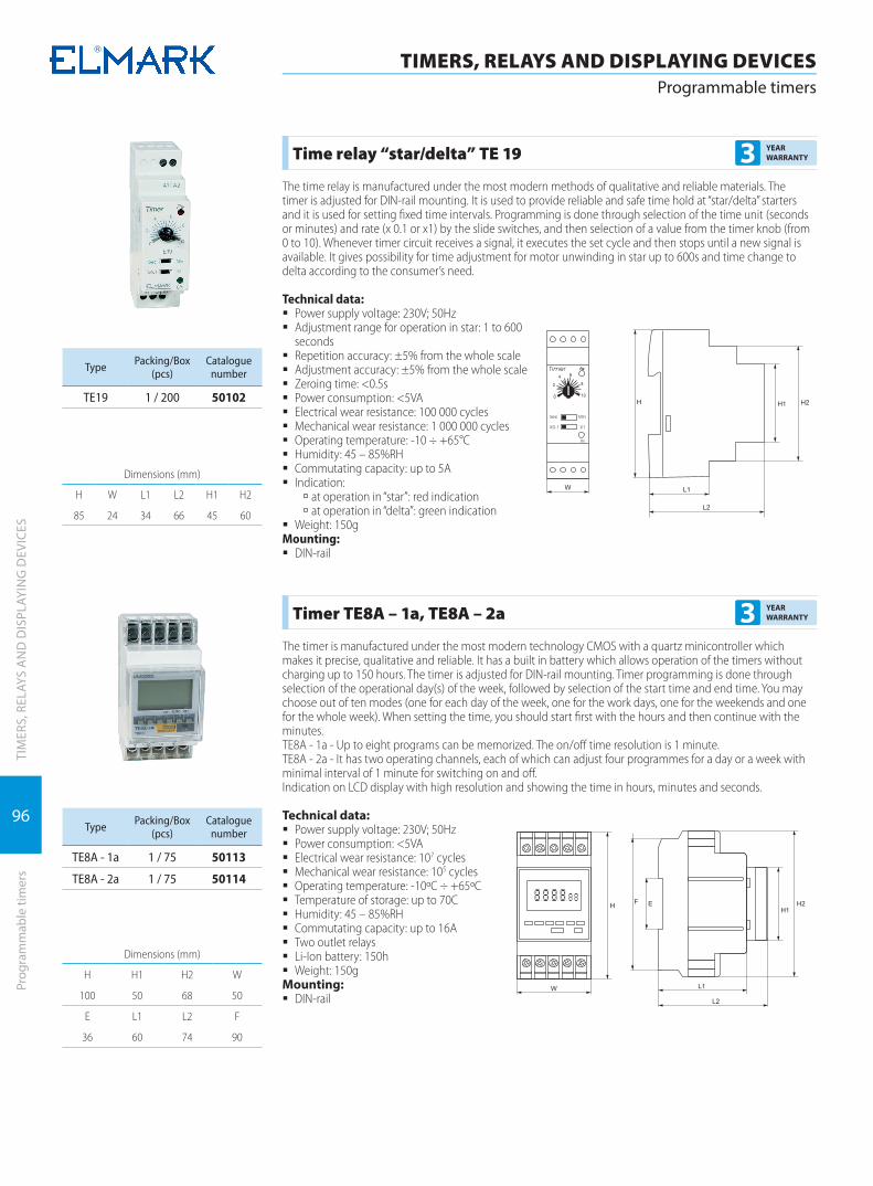
96
TIM
ERS,
REL
AYS
AN
D D
ISPL
AYIN
G D
EVIC
ES
TIMERS, RELAYS AND DISPLAYING DEVICESProgrammable timers
Prog
ram
mab
le ti
mer
s
Dimensions (mm)
H W L1 L2 H1 H2
85 24 34 66 45 60
Time relay “star/delta” TE 19 3 YEAR WARRANTY
The time relay is manufactured under the most modern methods of qualitative and reliable materials. The timer is adjusted for DIN-rail mounting. It is used to provide reliable and safe time hold at “star/delta” starters and it is used for setting fixed time intervals. Programming is done through selection of the time unit (seconds or minutes) and rate (x 0.1 or x1) by the slide switches, and then selection of a value from the timer knob (from 0 to 10). Whenever timer circuit receives a signal, it executes the set cycle and then stops until a new signal is available. It gives possibility for time adjustment for motor unwinding in star up to 600s and time change to delta according to the consumer’s need.
Technical data: � Power supply voltage: 230V; 50Hz � Adjustment range for operation in star: 1 to 600
seconds � Repetition accuracy: ±5% from the whole scale � Adjustment accuracy: ±5% from the whole scale � Zeroing time: <0.5s � Power consumption: <5VA � Electrical wear resistance: 100 000 cycles � Mechanical wear resistance: 1 000 000 cycles � Operating temperature: -10 ÷ +65°C � Humidity: 45 – 85%RH � Commutating capacity: up to 5A � Indication:
à at operation in “star”: red indication à at operation in “delta”: green indication
� Weight: 150gMounting:
� DIN-rail
Type Packing/Box (pcs)
Cataloguenumber
TE19 1 / 200 50102
Dimensions (mm)
H H1 H2 W
100 50 68 50
E L1 L2 F
36 60 74 90
Timer TE8A – 1a, TE8A – 2a 3 YEAR WARRANTY
The timer is manufactured under the most modern technology CMOS with a quartz minicontroller which makes it precise, qualitative and reliable. It has a built in battery which allows operation of the timers without charging up to 150 hours. The timer is adjusted for DIN-rail mounting. Timer programming is done through selection of the operational day(s) of the week, followed by selection of the start time and end time. You may choose out of ten modes (one for each day of the week, one for the work days, one for the weekends and one for the whole week). When setting the time, you should start first with the hours and then continue with the minutes.ТЕ8A - 1a - Up to eight programs can be memorized. The on/off time resolution is 1 minute.ТЕ8A - 2a - It has two operating channels, each of which can adjust four programmes for a day or a week with minimal interval of 1 minute for switching on and off.Indication on LCD display with high resolution and showing the time in hours, minutes and seconds.
Technical data: � Power supply voltage: 230V; 50Hz � Power consumption: <5VA � Electrical wear resistance: 107 cycles � Mechanical wear resistance: 105 cycles � Operating temperature: -10ºC ÷ +65ºC � Temperature of storage: up to 70C � Humidity: 45 – 85%RH � Commutating capacity: up to 16A � Two outlet relays � Li-Ion battery: 150h � Weight: 150g
Mounting: � DIN-rail
Type Packing/Box (pcs)
Cataloguenumber
ТЕ8А - 1а 1 / 75 50113
ТЕ8А - 2а 1 / 75 50114

97
TIM
ERS,
REL
AYS
AN
D D
ISPL
AYIN
G D
EVIC
ESPr
ogra
mm
able
tim
ers
TIMERS, RELAYS AND DISPLAYING DEVICESProgrammable timers
Dimensions (mm)
H W C D L1 L2
85 24 36 45 34 66
Impulse relay 3 YEAR WARRANTY
Impulse relays allow circuit remote control. They can be operated manually, remotely, from several control points, or by impulses. Impulse relays are most frequently used for the control of lighting circuits in various public places with multiple control points.
Technical data: � Control voltage: 230V � Rated current of the power circuit: 16А � Electrical endurance: 200000 cycles � Maximum switching frequency: 5 operations/minute � Impulse duration: 50ms
Connection: � tunnel terminals
Type Packing/Box (pcs)
Cataloguenumber
EPN510 8 / 160 50300
Dimensions (mm)
D W L
8.5 45 80
Timer TE6B 3 YEAR WARRANTY
The timer is manufactured under the most modern technology CMOS with a quartz minicontroller which makes it precise, qualitative and reliable. The timer is modulated to be mounted on the front panel of boards. The direction of operation is adjusted – direct or reverse. There is possibility to adjust the time range from 0.01 second to 99 hours 59 minutes, possibility for correction of the set values during operation. Indication on LCD display with high resolution and showing the time in hours, minutes and seconds.
Technical data: � Power supply voltage: 230V; 50Hz � Possibility for choice of operating range:
à from 0.01 second to 99.99 seconds à from 1 second to 99.59 minutes à from 1 minute to 99.59 hours
� Error: <0.01% ±0.05s � Minimal duration of the input pulse: 20ms � Power consumption: <5VA � Electrical wear resistance: 107 cycles � Mechanical wear resistance: 105 cycles � Operating temperature: -10 ÷ +65°C � Temperature of storage: up to 70°C � Humidity: 45 – 85%RH � Commutating capacity at active load: 3A � Weight: 300g
Mounting: � on the front panel of the board
Type Packing/Box (pcs)
Cataloguenumber
TE6B 1 / 100 50104
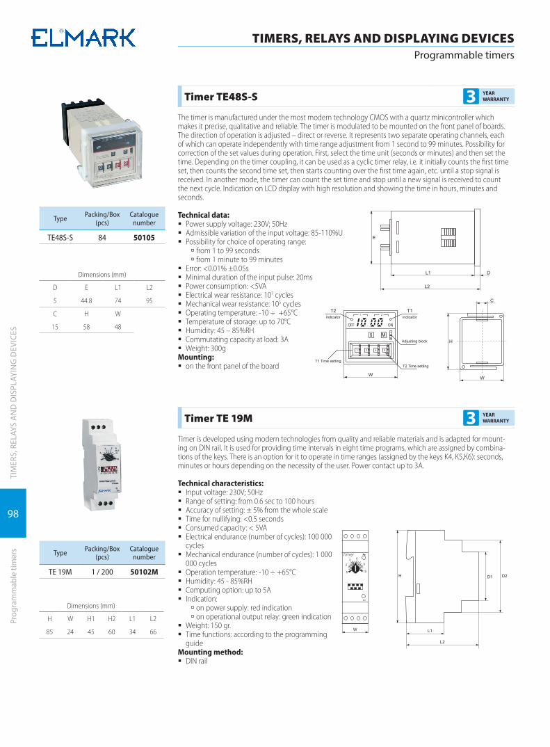
98
TIM
ERS,
REL
AYS
AN
D D
ISPL
AYIN
G D
EVIC
ES
TIMERS, RELAYS AND DISPLAYING DEVICESProgrammable timers
Prog
ram
mab
le ti
mer
s
Dimensions (mm)
D E L1 L2
5 44.8 74 95
C H W
15 58 48
Timer TE48S-S 3 YEAR WARRANTY
The timer is manufactured under the most modern technology CMOS with a quartz minicontroller which makes it precise, qualitative and reliable. The timer is modulated to be mounted on the front panel of boards. The direction of operation is adjusted – direct or reverse. It represents two separate operating channels, each of which can operate independently with time range adjustment from 1 second to 99 minutes. Possibility for correction of the set values during operation. First, select the time unit (seconds or minutes) and then set the time. Depending on the timer coupling, it can be used as a cyclic timer relay, i.e. it initially counts the first time set, then counts the second time set, then starts counting over the first time again, etc. until a stop signal is received. In another mode, the timer can count the set time and stop until a new signal is received to count the next cycle. Indication on LCD display with high resolution and showing the time in hours, minutes and seconds.
Technical data: � Power supply voltage: 230V; 50Hz � Admissible variation of the input voltage: 85-110%U � Possibility for choice of operating range:
à from 1 to 99 seconds à from 1 minute to 99 minutes
� Error: <0.01% ±0.05s � Minimal duration of the input pulse: 20ms � Power consumption: <5VA � Electrical wear resistance: 107 cycles � Mechanical wear resistance: 105 cycles � Operating temperature: -10 ÷ +65°C � Temperature of storage: up to 70°C � Humidity: 45 – 85%RH � Commutating capacity at load: 3A � Weight: 300g
Mounting: � on the front panel of the board
Type Packing/Box (pcs)
Cataloguenumber
TE48S-S 84 50105
Dimensions (mm)
H W H1 H2 L1 L2
85 24 45 60 34 66
Timer ТЕ 19M 3 YEAR WARRANTY
Timer is developed using modern technologies from quality and reliable materials and is adapted for mount-ing on DIN rail. It is used for providing time intervals in eight time programs, which are assigned by combina-tions of the keys. There is an option for it to operate in time ranges (assigned by the keys K4, K5,K6): seconds, minutes or hours depending on the necessity of the user. Power contact up to 3A.
Technical characteristics: � Input voltage: 230V; 50Hz � Range of setting: from 0.6 sec to 100 hours � Accuracy of setting: ± 5% from the whole scale � Time for nullifying: <0.5 seconds � Consumed capacity: < 5VA � Electrical endurance (number of cycles): 100 000
cycles � Mechanical endurance (number of cycles): 1 000
000 cycles � Operation temperature: -10 ÷ +65°С � Humidity: 45 - 85%RH � Computing option: up to 5А � Indication:
à on power supply: red indication à on operational output relay: green indication
� Weight: 150 gr. � Time functions: according to the programming
guideMounting method:
� DIN rail
Type Packing/Box (pcs)
Cataloguenumber
ТЕ 19M 1 / 200 50102M
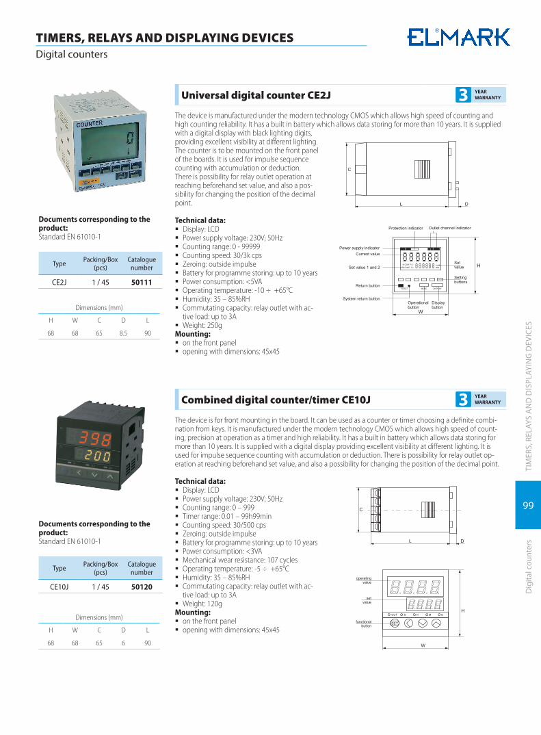
99
TIM
ERS,
REL
AYS
AN
D D
ISPL
AYIN
G D
EVIC
ESD
igita
l cou
nter
s
TIMERS, RELAYS AND DISPLAYING DEVICESDigital counters
Dimensions (mm)
H W C D L
68 68 65 8.5 90
Universal digital counter CE2J 3 YEAR WARRANTY
The device is manufactured under the modern technology CMOS which allows high speed of counting and high counting reliability. It has a built in battery which allows data storing for more than 10 years. It is supplied with a digital display with black lighting digits, providing excellent visibility at different lighting. The counter is to be mounted on the front panel of the boards. It is used for impulse sequence counting with accumulation or deduction. There is possibility for relay outlet operation at reaching beforehand set value, and also a pos-sibility for changing the position of the decimal point.
Technical data: � Display: LCD � Power supply voltage: 230V; 50Hz � Counting range: 0 - 99999 � Counting speed: 30/3k cps � Zeroing: outside impulse � Battery for programme storing: up to 10 years � Power consumption: <5VA � Operating temperature: -10 ÷ +65°C � Humidity: 35 – 85%RH � Commutating capacity: relay outlet with ac-
tive load: up to 3A � Weight: 250g
Mounting: � on the front panel � opening with dimensions: 45x45
Documents corresponding to the product:Standard EN 61010-1
Type Packing/Box (pcs)
Cataloguenumber
CE2J 1 / 45 50111
Dimensions (mm)
H W C D L
68 68 65 6 90
Combined digital counter/timer CE10J 3 YEAR WARRANTY
The device is for front mounting in the board. It can be used as a counter or timer choosing a definite combi-nation from keys. It is manufactured under the modern technology CMOS which allows high speed of count-ing, precision at operation as a timer and high reliability. It has a built in battery which allows data storing for more than 10 years. It is supplied with a digital display providing excellent visibility at different lighting. It is used for impulse sequence counting with accumulation or deduction. There is possibility for relay outlet op-eration at reaching beforehand set value, and also a possibility for changing the position of the decimal point.
Technical data: � Display: LCD � Power supply voltage: 230V; 50Hz � Counting range: 0 – 999 � Timer range: 0.01 – 99h99min � Counting speed: 30/500 cps � Zeroing: outside impulse � Battery for programme storing: up to 10 years � Power consumption: <3VA � Mechanical wear resistance: 107 cycles � Operating temperature: -5 ÷ +65°C � Humidity: 35 – 85%RH � Commutating capacity: relay outlet with ac-
tive load: up to 3A � Weight: 120g
Mounting: � on the front panel � opening with dimensions: 45x45
Documents corresponding to the product:Standard EN 61010-1
Type Packing/Box (pcs)
Cataloguenumber
CE10J 1 / 45 50120

100
TIM
ERS,
REL
AYS
AN
D D
ISPL
AYIN
G D
EVIC
ES
TIMERS, RELAYS AND DISPLAYING DEVICESDigital counters
Dig
ital c
ount
ers
Total digital counter CE15J 3 YEAR WARRANTY
The device is to be mounted on DIN-rail. It is used as an impulse counter with no outside power supply. For that purpose there is a Li battery built in the device which provides data storing and operation of the device for 5 years. It has eight digital lighting display providing excellent visibility at different lighting. It is used for impulse sequence counting with accumulation.
Technical data: � Display: LCD � Power supply voltage: built in battery � Inlet signal: 100-230V AC/DC � Counting accuracy: <0.002% � Data storing battery: up to 5 years � Operating temperature: -5 ÷ +65°C � Humidity: 35 – 85%RH � Weight: 120g
Mounting: � DIN-rail
Dimensions (mm)
H W D L
86 36 45 64
Documents corresponding tothe product: EN 61010-1
Type Packing/Box (pcs)
Cataloguenumber
CE15J 1 / 100 50112
Total digital counter CE15L 3 YEAR WARRANTY
The device is to be mounted on DIN-rail. It is used as a time impulse counter with no outside power supply. For that purpose there is a Li battery built in the device which provides data storing and operation of the device for 5 years. It has eight digital lighting display providing excellent visibility at different lighting. It is used for time impulse sequence counting with accumulation. It displays the operated time.
Technical data: � Display: LCD � Power supply voltage: built in battery � Inlet signal: 100-230V AC/DC � Counting accuracy: <0.002% � Battery for data storing: up to 5 years � Operating temperature: -5 ÷ +65°C � Humidity: 35 – 85%RH � Weight: 120g
Mounting: � DIN-rail
Dimensions (mm)
H W D L
86 36 45 64
Documents corresponding tothe product: EN 61010-1
Type Packing/Box (pcs)
Cataloguenumber
CE15L 1 / 100 50115
Dimensions (mm)
H W D1 D2 L1 L2
85 24 45 60 34 66
Phase sequence indicator EK - RSTB 3 YEAR WARRANTY
The device is to be mounted on DIN-rail. It is used for control and indication of the presence, sequence and quality of the phases. The device indicates the following fault:
� lack of one or several phases; � change in the sequence of the phases; � lowering of the power supplying voltage: under 10%; � increasing of the power supplying voltage: over 10%; � phase asymmetry of the power supplying voltage: ±10%
In the presence of one of the conditions above a relay starts operating in the device which breaks the control-ling circuit.The time between fault indication and outlet relay switching on can be adjusted in order to prevent unwilling stops at very short breaks. When the voltage is back to normal limits, the device receives energy (indication lights) according to the hysteresic values. At phase sequence fault the device operates immediately.
Technical data: � Power supply voltage: 400V; 50Hz � Possibility for operation range adjustment: 0.1 – 10
seconds � Possibility for working range adjustment: from 300 to
480 V � Electrical wear resistance: 1 000 000 cycles � Mechanical wear resistance: 10 000 000 cycles � Indication:
à green LED – indication for a change in the condition à red LED - failure
� Operating temperature: -5 ÷ +65°C � Humidity: 35 – 85%RH � Weight: 120g
Mounting: � DIN-rail
Documents corresponding tothe product: EN 61010-1
Type Packing/Box (pcs)
Cataloguenumber
EK - RSTB 1 / 200 50103

101
TIM
ERS,
REL
AYS
AN
D D
ISPL
AYIN
G D
EVIC
ESIn
dust
rial r
elay
s
TIMERS, RELAYS AND DISPLAYING DEVICESIndustrial relays
Industrial Relays and Bases 3 YEAR WARRANTY
Devices intended for construction of automation and signalling boards. They are mainly used for command transfer towards the executive mechanisms. Currents of comparatively heavy values enabling the direct control of industrial executive mechanisms are commuted in comparatively small sizes. The contact surfaces are made from silver-coated electrolytic copper. The entire contact system is closed within a lid of colourless fire-proof plastic with a test-button installed to it. The base provides a safe electric connection of the conductors of the electric installation and the relays and is used to install the relay to the DIN busbar.
Technical Characteristics: � Supply voltage: from 12 to 230V АС, 50 Нz and from 12 to 110V DC � Acceptable deviation of the supply voltage: 85 -110% Un � Rated current of the sockets: 10А АС � Electrical endurance: 1 000 000 cycles � Isolation resistance: 500 mΩ /min (500V) � Impulse tension resistance: 2000V, 50Нz � Dielectric strength: 1000V АС/1 min � Turn-out time: 25ms � Working temperature: -5 ÷ + 65°С � Humidity: 35 - 85% RH
Method of installation: � on a DIN rail by means of a socket
Documents corresponding tothe product: EN 60947-5-1;EN 61810
Relay type Voltage of the coil (V) Socket type Resistance of the
coil ( Ω )Number of
contactsPacking/Box
(pcs)Catalogue
number
ELM - 14FC 12 VDC ELM-RT624-B 260 NO+NC 100 / 1000 57141ELM - 14FC 24 VDC ELM-RT624-B 1080 NO+NC 100 / 1000 57142ELM - 14FC 48 VDC ELM-RT624-B 4260 NO+NC 100 / 1000 57143
Relay type Voltage of the coil (V) Socket type Resistance of the
coil ( Ω )Number of
contactsPacking/Box
(pcs)Catalogue
number
ELM - 60.2 12 VDC ELM - 90.22 96 2NO+2NC 20 / 300 57601ELM - 60.2 24 VDC ELM - 90.22 384 2NO+2NC 20 / 300 57602ELM - 60.2 48 VDC ELM - 90.22 1540 2NO+2NC 20 / 300 57603ELM - 60.2 230 VAC ELM - 90.22 7400 2NO+2NC 20 / 300 57605ELM-60.2 24VAC ELM-90.22 2NO+2NC 20 / 300 57606ELM - 60.13 12 VDC ELM - 90.23 96 3NO+3NC 20 / 300 57611ELM - 60.13 24 VDC ELM - 90.23 384 3NO+3NC 20 / 300 57612ELM - 60.13 48 VDC ELM - 90.23 1540 3NO+3NC 20 / 300 57613ELM - 60.13 110 VAC ELM - 90.23 1700 3NO+3NC 20 / 300 57614ELM - 60.13 230 VAC ELM - 90.23 7400 3NO+3NC 20 / 300 57615ELM-60.13 24VAC ELM90.23 3NO-3NC 20/300 57616
Relay type Voltage of the coil (V) Socket type Resistance of the
coil ( Ω )Number of
contactsPacking/Box
(pcs)Catalogue
number
ELM - 55.02 12 VDC ELM - RT702-B 42 2NO+2NC 50 / 500 57521ELM - 55.02 24 VDC ELM - RT702-B 168 2NO+2NC 50 / 500 57522ELM - 55.02 48 VDC ELM - RT702-B 675 2NO+2NC 50 / 500 57523ELM - 55.02 230 VAC ELM - RT702-B 14000 2NO+2NC 50 / 500 57525ELM55.02 24VAC ELM - RT702-B 2NO+2NC 50/500 57526ELM - 55.04 12 VDC ELM-RT704-B 42 4NO+4NC 50 / 500 57541ELM - 55.04 24 VDC ELM-RT704-B 168 4NO+4NC 50 / 500 57542ELM - 55.04 48 VDC ELM-RT704-B 675 4NO+4NC 50 / 500 57543ELM - 55.04 110 VAC ELM-RT704-B 3500 4NO+4NC 50 / 500 57544ELM - 55.04 230 VAC ELM-RT704-B 14000 4NO+4NC 50 / 500 57545ELM-55.04 24VAC ELM-RT704-B 4NO+4NC 50/500 57546
Socket type Dimensions (mm) Number of terminals (pcs.) Packing/Box (pcs) Catalogue number
ELM - RT624-B 76 x 15 5 20 / 600 57901ELM - RT702-B 76 x 27 11 10 / 240 57902ELM - RT704-B 76 x 27 14 10 / 240 57912ELM - 90.22 68 x 38 8 10 / 400 57904ELM - 90.23 68 x 38 11 10 / 400 57905

102
TIM
ERS,
REL
AYS
AN
D D
ISPL
AYIN
G D
EVIC
ES
TIMERS, RELAYS AND DISPLAYING DEVICESIndustrial relays
Indu
stria
l rel
ays
Industrial Solid State Relays (SSR) 3 YEAR WARRANTY
Industrial SSR are intended for mounting in power and control cabinets as an output switch devices with reliable ON/OFF performance. The SSR are based on the CMOS technology. The non-contact electronic switch is optically separated from the input signal by a photoelectric coupler. This allows use of switch currents of up to 50A despite of the devices small overall size. Another important feature of the relay is that output load can be regulated depending on the input signal value. The relay is mainly used to transmit control signals to actuating mechanisms since it can work at compara-tively high currents making it possible to directly control actuators. SSR have transparent plastic covers to additionally improve their safety level. The SSR use is connected with considerable heat emissions, so measures must be taken to dispense the excessive thermal energy in the atmosphere. This is achieved through application of specially deigned radiators. The correct definition of radiator parameters is of critical importance. It is made by calculating the heat genera-tion capacity with the formula: Heat generation = active load current x 3.0 W/A. The heat removal surface is estimated with the help of the following graphic:
Technical Specifications: � Load/output voltage: 30/400V 50 Hz or the solid state voltage
regulators � Rated output current: from 10А to 60А � Insulating voltage: 1000 MΩ /min (500V) � Impulse voltage stability: 2000V, 50Hz � Dielectric Strength: < 2500VAC / 1 min � Leakage current: <2mA � Turn-on time: <10ms � Operating temperature: -5°С + 65°С � Relative Humidity: 35 - 85%RH
Documents corresponding tothe product: EN 60947-5-1;EN 61810
Type Relay Type Control Volt-age (V)
Output Volt-age (V)
Number ofphases
Output Cur-rent ( А )
Packing/Box (pcs)
Cataloguenumber
ZG3NC - 2 - 10B SSR 3-32VDC 230VАC 1 10 10 / 100 57710ZG3NC - 2 - 20B SSR 3-32VDC 230VАC 1 20 10 / 100 57720ZG3NC - 2 - 25B SSR 3-32VDC 230VАC 1 25 10 / 100 57725ZG3NC - 2 - 40B SSR 3-32VDC 230VАC 1 40 10 / 100 57740ZG3NC - 2 - 60B SSR 3-32VDC 230VАC 1 60 10 / 100 57760ZG3NC - 3 -10B SSR 3-32VDC 400VАC 2 10 10 / 100 57713ZG3NC - 3 - 20B SSR 3-32VDC 400VАC 2 20 10 / 100 57723ZG3NC - 3 - 25B SSR 3-32VDC 400VАC 2 25 10 / 100 57735ZG3NC - 3 - 40B SSR 3-32VDC 400VАC 2 40 10 / 100 57743ZG3NC - 3 - 60B SSR 3-32VDC 400VАC 2 60 10 / 100 57763
Type Relay Type Control Voltage (V)
Output Volt-age (V)
Number ofphases
Output Cur-rent ( А )
Packing/Box (pcs)
Cataloguenumber
ZG1NC - 2 - 10D SS voltage regulator 1-10VDC 0-230VАC 1 10 10 / 100 57810ZG1NC - 2 - 20D SS voltage regulator 1-10VDC 0-230VАC 1 20 10 / 100 57820ZG1NC - 2 - 25D SS voltage regulator 1-10VDC 0-230VАC 1 25 10 / 100 57825ZG1NC - 2 - 40D SS voltage regulator 1-10VDC 0-230VАC 1 40 10 / 100 57840ZG1NC - 3 -10D SS voltage regulator 1-10VDC 0-400VАC 2 10 10 / 100 57813ZG1NC - 3 - 20D SS voltage regulator 1-10VDC 0-400VАC 2 20 10 / 100 57823ZG1NC - 3 - 25D SS voltage regulator 1-10VDC 0-400VАC 2 25 10 / 100 57835ZG1NC - 3 - 40D SS voltage regulator 1-10VDC 0-400VАC 2 40 10 / 100 57843
Type Relay Type Control Volt-age (V)
Output Volt-age (V)
Number ofphases
Output Cur-rent ( А )
Packing/Box (pcs)
Cataloguenumber
ZG33 - 3 - 10В SSR 3-32VDC 400VАC 3 10 1 / 30 57831ZG33 - 3 - 20В SSR 3-32VDC 400VАC 3 20 1 / 30 57832ZG33 - 3 - 25В SSR 3-32VDC 400VАC 3 25 1 / 30 57833ZG 33 - 3 - 40В SSR 3-32VDC 400VАC 3 40 1 / 30 57834
Note: The relay output must be supplied with a varistor to ensure its over-voltage protection, whenever RRS is used to control inductive loads.
Type of Radiator Overall Dimensions (L/W/H) Approximate Load (A) Packing/Box (pcs) Catalogue
number
QW-A 50 60 x 50 x 50 15 1 / 50 57906QW-B 72 72x100x50 20 1 / 50 57907
QW-B 100 100x100x50 25 1 / 50 57908QW-C 115 115x100x50 40 1 / 50 57909QW-E 50 150x88x35 75 1 / 40 57910

103
TIM
ERS,
REL
AYS
AN
D D
ISPL
AYIN
G D
EVIC
ESCu
rren
t mea
sure
men
t tra
nsfo
rmer
s
TIMERS, RELAYS AND DISPLAYING DEVICESCurrent measurement transformers
Current measurement transformers MES - xx/xx type 3 YEAR WARRANTY
The measurement transformers find application at current measuring, current regulation, systems for current characteristics watching, systems for reactive energy compensation, signaling, etc. They are with x/5 gear ratio as X is the inlet range of the transformer.
Technical data: � Maximum operating voltage: 720V; 50Hz � Admissible deviation of the operating current: 1.2 x In � Inlet current: 50 – 1200A � Outlet current: 5A � Impulse voltage wear resistance: 4000V; 50Hz (1min) � Operating temperature: -5 ÷ +65°C � Humidity: 35 – 85%RH � Precision class: 0.5
Mounting: � Current transformers can be DIN rail mounted; � vertically or horizontally to the power supplying rails according to the opening of the transformer � Current transformers can be mounted on flat surfaces by use of fixing clamps.
Documents corresponding tothe product: Standard EN 61010-1;EN 60044-1; EN 60044-6
TypeOverall dimensions (mm)
A B C D E F G
MES - 75/30 88 52 52 41 77 31 31
MES - 75/40 88 52 52 41 77 41 41
MES - 86/60 117 57 57 184 77 61 61
Type Range Precision class Capacity VA Weight kg Packing/Box (pcs)
Cataloguenumber
MES - 75/30 50/5 0.5 1.5 0.60 1 / 40 45050А
MES - 75/30 75/5 0.5 1.5 0.60 1 / 40 45075А
MES - 75/30 100/5 0.5 1.5 0.60 1 / 40 45103А
MES - 75/30 150/5 0.5 2.5 0.60 1 / 40 45153А
Type Range Precision class Capacity VA Weight kg Packing/Box (pcs)
Cataloguenumber
MES - 75/40 200/5 0.5 5 0.60 1 / 40 45204А
MES - 75/40 250/5 0.5 5 0.60 1 / 40 45254А
MES - 75/40 300/5 0.5 10 0.60 1 / 40 45304А
MES - 75/40 400/5 0.5 10 0.60 1 / 40 45404А
MES - 75/40 500/5 0.5 10 0.60 1 / 40 45504А
MES - 75/40 600/5 0.5 15 0.60 1 / 40 45604А
Type Range Precision class Capacity VA Weight kg Packing/Box (pcs)
Cataloguenumber
MES - 86/60 400/5 0.5 15 0.60 1 / 40 45406А
MES - 86/60 500/5 0.5 15 0.60 1 / 40 45506А
MES - 86/60 600/5 0.5 15 0.60 1 / 40 45606А
MES - 86/60 800/5 0.5 15 0.60 1 / 40 45806А
MES - 86/60 1000/5 0.5 15 0.60 1 / 32 45906А
MES - 86/60 1200/5 0.5 15 0.60 1 / 32 45916А

104
TIM
ERS,
REL
AYS
AN
D D
ISPL
AYIN
G D
EVIC
ES
TIMERS, RELAYS AND DISPLAYING DEVICESCurrent measurement transformers
Curr
ent m
easu
rem
ent t
rans
form
ers
Current transformers, type СР 3 YEAR WARRANTY
Current measuring transformers of duct type. Specially designed to be installed in measuring circuits without removing cables in current measuring circuit. CP Transformers save installation time and decrease installation costs
Technical Specification: � small size table: � secondary coil rated current 5А � rated voltage 720V � frequency 50Hz � rated load: up to 30VA � safety coefficient: fs≤5 � accuracy class :0.5; 1 � secondary coil connection: cable shoe terminal
Documents corresponding tothe product: Standard EN 60044-1
TypeOverall dimensions (mm)
A B C D E F G
СР 23 20 30 51 89 111 34 47
СР 58 50 80 78 114 145 32 32
СР 88 80 80 108 144 145 32 32
Type Range Precision class Capacity VA Weight kg Packing/Box (pcs)
Cataloguenumber
СР 23 200/5 1 1.5 0,74 1 / 45 452320
СР 23 250/5 1 1,5 0,74 1 / 45 452325
СР 23 300/5 0,5 1,5 0,74 1 / 45 452330
Type Range Precision class Capacity VA Weight kg Packing/Box (pcs)
Cataloguenumber
СР 58 250/5 0,5 1,5 0,87 1 / 36 455825
СР 58 300/5 0,5 1,5 0,87 1 / 36 455830
СР 58 400/5 0,5 1,5 0,87 1 / 36 455840
СР 58 500/5 0,5 2,5 0,87 1 / 36 455850
СР 58 600/5 0,5 2,5 0,87 1 / 36 455860
Type Range Precision class Capacity VA Weight kg Packing/Box (pcs)
Cataloguenumber
СР 88 400/5 0,5 1,5 1 1 / 20 458840
СР 88 500/5 0,5 1,5 1 1 / 20 458850
СР 88 600/5 0,5 1,5 1 1 / 20 458860
СР 88 750/5 0,5 2,5 1 1 / 20 458875
СР 88 800/5 0,5 2,5 1 1 / 20 458880
СР 88 1000/5 0,5 5 1 1 / 20 458890

105
TIM
ERS,
REL
AYS
AN
D D
ISPL
AYIN
G D
EVIC
ESVo
ltage
tran
sfor
mer
s
TIMERS, RELAYS AND DISPLAYING DEVICESVoltage transformers
EVT5 - control voltage transformer 3 YEAR WARRANTY
Functions:Reduction of main voltage within standard range
� Galvanic separation of the power supply circuit from the operation circuitTechnical features:
� Input voltage: 400 or 230 V � Frequency : 50/60Hz � Short circuit resistance: unstable � Temperature class: В (130ºC) � Construction: open (for installation in other products) � Magnetic circuit: cold rolled electric furnace steel � Coils: pure electrotechnical copper � IP code: IP20
Connection: � flexible or hard conductors of relevant section to terminals
Mounting: � Mounting in distribution boards or products � fastening: by means of screws/bolts to the surface � position: vertical � ambient temperature: -20 ÷ +65ºС
Documents corresponding to the product:Standard EN 60051-1
TypeInitial
voltage(V)
Secondaryvoltage
(V)
PowerVA
Dimensions Packing / Box (pcs.)
Catalogue numberC D E F G d
EVT5 - 100VA 230 48-36 100 84 90 63 65 95 4 16 45248EVT5 - 100VA 400 48-36 100 84 90 63 65 95 4 16 45448EVT5 - 100VA 230 24-12 100 84 90 63 65 95 4 16 45243EVT5 - 100VA 400 24-12 100 84 90 63 65 95 4 16 45443EVT5 - 250VA 230 48-24-12 250 130 100 120 53 130 20 16 45242EVT5 - 250VA 230 48-36 250 130 100 120 53 130 20 16 45242NEVT5 - 250VA 400 48-24-12 250 130 100 120 53 130 20 12 45442EVT5 - 250VA 400 48-36 250 130 100 120 53 130 20 12 45442NEVT5 - 250VA 230 24-12 250 130 100 120 53 130 20 12 45244EVT5 - 250VA 400 24-12 250 130 100 120 53 130 20 12 45444EVT5 - 500VA 230 48-24-12 500 150 113 133 53 140 20 4 45245EVT5 - 500VA 230 48-36 500 150 113 133 53 140 20 4 45245NEVT5 - 500VA 400 48-24-12 500 150 113 133 53 140 20 4 45445EVT5 - 500VA 400 48-36 500 150 113 133 53 140 20 4 45445N EVT5 - 500VA 230 24-12 500 150 125 133 53 140 20 4 45246 EVT5 - 500VA 400 24-12 500 150 125 133 53 140 20 4 45446 EVT5 - 500VA 230 110-48-24 500 150 125 133 53 140 20 4 45215 EVT5 - 500VA 400 110-48-24 500 150 125 133 53 140 20 6 45415EVT5 -1000VA 230 48-24-12 1000 170 125 150 65 155 20 2 45241EVT5 -1000VA 230 48-36 1000 170 125 150 65 155 20 2 45241NEVT5 - 1000VA 400 48-24-12 1000 170 125 150 65 155 20 2 45441EVT5 - 1000VA 400 48-36 1000 170 125 150 65 155 20 2 45441NEVT5 - 1000VA 230 24-12 1000 170 125 150 65 155 20 2 45247EVT5 - 1000VA 400 24-12 1000 170 125 150 65 155 20 2 45447EVT5 - 1600VA 230 48-24-12 1600 190 125 150 65 170 20 2 452416EVT5 - 1600VA 230 48-36 1600 190 125 150 65 170 20 2 452416NEVT5 - 1600VA 400 48-24-12 1600 190 125 150 65 170 20 2 454416EVT5 - 1600VA 400 48-36 1600 190 125 150 65 170 20 2 454416NEVT5 - 1600VA 230 24-12 1600 190 125 150 65 170 20 2 452417EVT5 - 1600VA 400 24-12 1600 190 125 150 65 170 20 2 454417

106
TIM
ERS,
REL
AYS
AN
D D
ISPL
AYIN
G D
EVIC
ES
TIMERS, RELAYS AND DISPLAYING DEVICESBell and bell transformer
Bell
and
bell
tran
sfor
mer
Bell 5 YEAR WARRANTY
Used for sound signalization in housing and industrial buildings. � Sound level: 70 dB
Consumption: � 3.6VA for power supply 8 -12V � 5VA for power supply 230V
Mounting on DIN-rail
Type Un (V) Packing / Box (pcs) Catalogue number
Bell 8-12 1 / 17 170 5012
Bell 230 1 / 17 170 5220
Bell transformer 5 YEAR WARRANTY
Modified for power supply of bells and other signal devices with alternating voltage 8V, 12V, 24V and capacity up to 3.8A.
� The voltage of the primary winding voltage is 230V � Mounting on DIN-rail
Type Packing / Box (pcs) Catalogue number
Bell transformer 1 / 80 5001

107
TIMERS, RELAYS AND DISPLAYING DEVICESDisplaying measurement devices
TIM
ERS,
REL
AYS
AN
D D
ISPL
AYIN
G D
EVIC
ESD
ispl
ayin
g m
easu
rem
ent d
evic
es
Digital Temperature Controller Type CD - 701 3 YEAR WARRANTY
The device is intended for industrial control and monitoring of temperature. It allows monitoring and adjust-ment of temperatures of up to 1999°С depending on the used sensor – thermocouple or thermoresistor. The device allowsprogramming of the used type of sensor (К (CA) ; J ( IC) PT 100, etc.) and the controller working range. It also allows selection of the control algorithm, error adjustment, indication hysteresis curve adjust-ment and alarm settings. The controller is intended for mounting on control panels. It is user friendly and can be set through the push buttons on the device front panel. The program can be password protected. When operational, the display shows the set temperature and the current temperature.
Technical Specifications: � Rated voltage: 230V, 50 Hz � Permissible voltage deviation: 85 - 110% Un � Input signal: from thermocouple, thermoresistor or unified signal (4-20mA; 0-10VDC) � Output: Relay � Emergency Output: Relay � Electrical life: 1 000 000 cycles. � Indication:
à Green LED – indicates the measured (current) temperature à Red LED – indicates the set temperature
� Insulation resistance: 20 MΩ /min (500V) � Impulse voltage stability: 2000V, 50Hz � Operating temperature: -5°С ÷ +65°С � Relative Humidity: 35 - 85%RH
Mounting: � on the front panel
Documents corresponding tothe product: Standard EN 61010-1
Type Packing/Box (pcs)
Cataloguenumber
CD - 701 1 50124
Thermocouple and thermo resistance 3 YEAR WARRANTY
The thermo-measuring elements are designed for measuring the temperature in the point of contact between the surface (warmed or cooled) and the thermo-element. They are a comparatively cheap and the most wide-spread method for temperature measurement. The thermocouples are produced by accumulating two conductors from a special measuring alloy in one common head. Each of these elements has a specific electromotive voltage at a specific temperature. The temperature measuring is based on the difference in the electromotive powers between the hot and the cool end of the thermocouple, while this difference in the form of voltage of several milivolts is supplied at the input of the thermoregulator, which displays the measured temperature. Each thermocouple is produced and calibrated for measuring of specific temperature ranges depending on the alloys of which it is made. When thermocouples measuring great distances from the thermoregulators are used (more than 15 points), it is obligatory to use compensatory cable corresponding to the type of the thermocouple. The thermo-resistant elements action is based on the capacity of specific alloys, very often Pt100 to change their resistance when the temperature is changed. For each temperature value is specified a value of resistance. This value is supplied at the input of the thermoregulator, which displays the measured temperature.Each thermoregulator operates with a specific type of thermo-element.
Type of thermo-element
Symbol Temperature range Type of catching Sizes of the
headSize of the
free endPacking/Box (pcs)
Cataloguenumber
K WRNT - 01 0 ÷ 400°C nut 30 x 35 1m 1 / 300 50K40G
K WRNT - 31 0 ÷ 400°C Bayonet 30 x 35 0.5m 1 / 200 50K40B
K WRNT - 13 0 ÷400°C explosion-proof Ø6 2m 1 / 200 50K40EX
J WRKT - 01 0 ÷400°C nut 30 x 35 1m 1 / 300 50J40G
J WRKT - 13 0 ÷400°C explosion-proof Ø6 2m 1 / 300 50J40EX
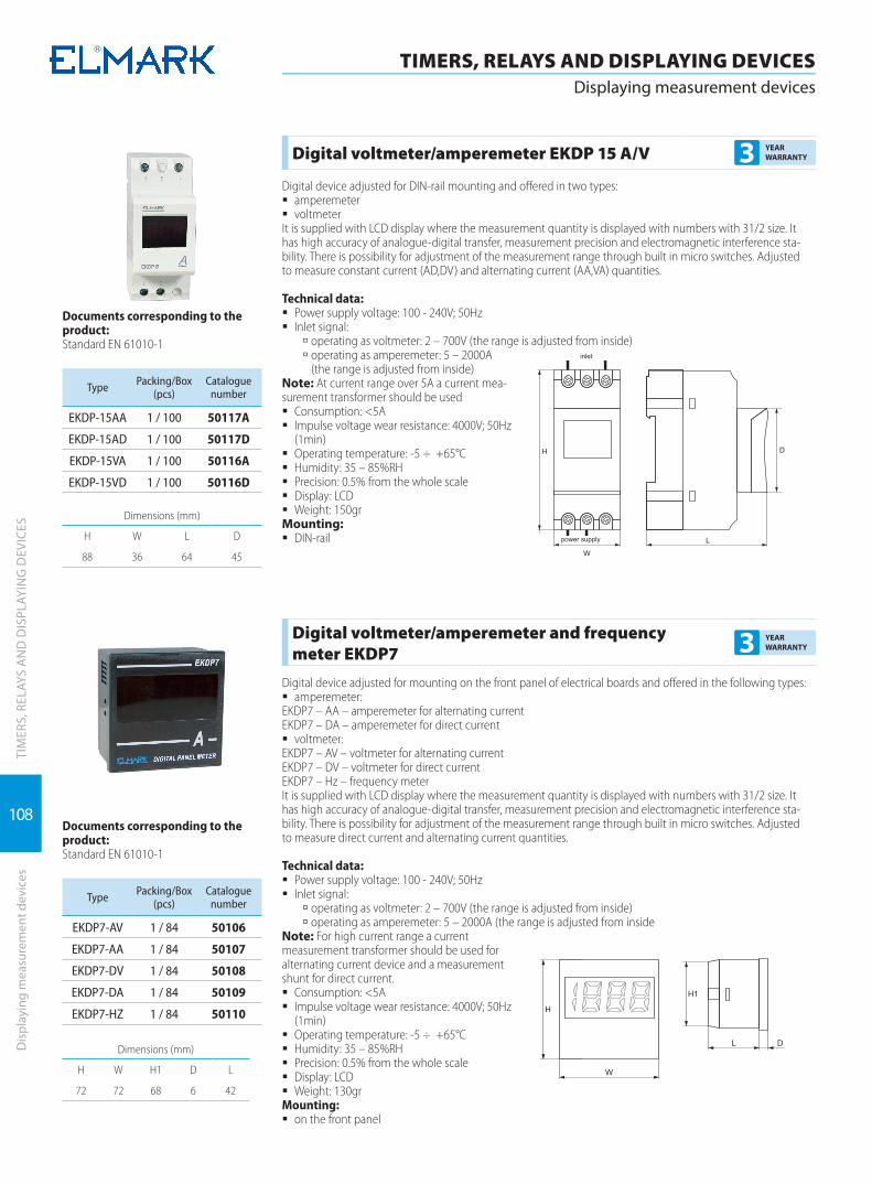
108
TIMERS, RELAYS AND DISPLAYING DEVICESDisplaying measurement devices
TIM
ERS,
REL
AYS
AN
D D
ISPL
AYIN
G D
EVIC
ESD
ispl
ayin
g m
easu
rem
ent d
evic
es
Digital voltmeter/amperemeter EKDP 15 A/V 3 YEAR WARRANTY
Digital device adjusted for DIN-rail mounting and offered in two types: � amperemeter � voltmeter
It is supplied with LCD display where the measurement quantity is displayed with numbers with 31/2 size. It has high accuracy of analogue-digital transfer, measurement precision and electromagnetic interference sta-bility. There is possibility for adjustment of the measurement range through built in micro switches. Adjusted to measure constant current (AD,DV) and alternating current (AA,VA) quantities.
Technical data: � Power supply voltage: 100 - 240V; 50Hz � Inlet signal:
à operating as voltmeter: 2 – 700V (the range is adjusted from inside) à operating as amperemeter: 5 – 2000A (the range is adjusted from inside)
Note: At current range over 5A a current mea-surement transformer should be used
� Consumption: <5A � Impulse voltage wear resistance: 4000V; 50Hz
(1min) � Operating temperature: -5 ÷ +65°C � Humidity: 35 – 85%RH � Precision: 0.5% from the whole scale � Display: LCD � Weight: 150gr
Mounting: � DIN-rail
Documents corresponding to the product:Standard EN 61010-1
Type Packing/Box (pcs)
Cataloguenumber
EKDP-15AA 1 / 100 50117A
EKDP-15AD 1 / 100 50117D
EKDP-15VA 1 / 100 50116A
EKDP-15VD 1 / 100 50116D
Dimensions (mm)
H W L D
88 36 64 45
Digital voltmeter/amperemeter and frequency meter EKDP7 3 YEAR
WARRANTY
Digital device adjusted for mounting on the front panel of electrical boards and offered in the following types: � amperemeter:
EKDP7 – AA – amperemeter for alternating currentEKDP7 – DA – amperemeter for direct current
� voltmeter:EKDP7 – AV – voltmeter for alternating currentEKDP7 – DV – voltmeter for direct currentEKDP7 – Hz – frequency meterIt is supplied with LCD display where the measurement quantity is displayed with numbers with 31/2 size. It has high accuracy of analogue-digital transfer, measurement precision and electromagnetic interference sta-bility. There is possibility for adjustment of the measurement range through built in micro switches. Adjusted to measure direct current and alternating current quantities.
Technical data: � Power supply voltage: 100 - 240V; 50Hz � Inlet signal:
à operating as voltmeter: 2 – 700V (the range is adjusted from inside) à operating as amperemeter: 5 – 2000A (the range is adjusted from inside
Note: For high current range a current measurement transformer should be used for alternating current device and a measurement shunt for direct current.
� Consumption: <5A � Impulse voltage wear resistance: 4000V; 50Hz
(1min) � Operating temperature: -5 ÷ +65°C � Humidity: 35 – 85%RH � Precision: 0.5% from the whole scale � Display: LCD � Weight: 130gr
Mounting: � on the front panel
Documents corresponding to the product:Standard EN 61010-1
Type Packing/Box (pcs)
Cataloguenumber
EKDP7-AV 1 / 84 50106
EKDP7-AA 1 / 84 50107
EKDP7-DV 1 / 84 50108
EKDP7-DA 1 / 84 50109
EKDP7-HZ 1 / 84 50110
Dimensions (mm)
H W H1 D L
72 72 68 6 42

109
TIMERS, RELAYS AND DISPLAYING DEVICESDisplaying measurement devices
TIM
ERS,
REL
AYS
AN
D D
ISPL
AYIN
G D
EVIC
ESD
ispl
ayin
g m
easu
rem
ent d
evic
es
Analogue (pointer) panel meters SD72 type for build-in 3 YEAR
WARRANTY
Analogue devices adjusted for mounting on the front panel of electrical boards. Designed for frequency mea-surement, capacity, alternating or direct voltage and current of the power supply grid, with overall dimensions 72x72mm. They are manufactured on the basis of bridge measurement schemes. There is possibility for display change for the higher scopes of measuring.
Documents corresponding to the product:Standard EN 60051-1
TypeType of the
measurment system
Precision class Range Note Packing/Box
(pcs)Catalogue
number
amperemeter АС MEMSI 1.5 0-40А - 1 / 100 50118
amperemeter АС MEMSI 1.5 0-100Аcurrent transfer
100/51 / 100 654010
amperemeter АС MEMSI 1.5 0-200Аcurrent transfer
200/51 / 100 654020
amperemeter АС MEMSI 1.5 0-400Аcurrent transfer
400/51 / 50 654040
amperemeter АС MEMSI 1.5 0-600Аcurrent transfer
600/51 / 50 654060
amperemeter АС MEMSI 1.5 0-1000Аcurrent transfer
1000/51 / 50 654100
amperemeter АС MEMSI 1.5 0-1500Аcurrent transfer
1500/51 / 50 654150
voltmeter АС* MEMSI 1.5 0-500V - 1 / 50 50125
frequency meter**
МЕ 0.5 45-65Hz - 1 / 50 50126
cosφ meter MEMSI 1.5 3P 400V - 1 / 50 50127
amperemeter DC MEMC 1.5 0-5A - 1 / 50 50128
amperemeter DC MEMC 1.5 0-50Aouter resistor
60mV1 / 50 50129
voltmeter DC MEMC 1.5 0-50V - 1 / 50 50130
voltmeter DC MEMC 1.5 0-100V - 1 / 20 50131
wattmeter MEMSI 1.50-3000W 1P240V
- 1 / 25 50132
wattmeter MEMSI 1.50-3000W 3P
3 line- 1 / 25 50133
wattmeter MEMSI 1.50-3000W 3P
4 line- 1 / 25 50134
Note: MEMSI - magnetic-electrical movable steel instrument; MEMC – magnetic-electrical movable coil* Possibility for supplying with voltage transformer X/100V for range expanding** Possibility for voltage 110V, 230V , 400V

110
TIMERS, RELAYS AND DISPLAYING DEVICESDisplaying measurement devices
TIM
ERS,
REL
AYS
AN
D D
ISPL
AYIN
G D
EVIC
ESD
ispl
ayin
g m
easu
rem
ent d
evic
es
DIN Rail Mounted kWh Meters 3 YEAR WARRANTY
Electronic single and three phase kWh meters intended for DIN rail mounting and active energy measure-ment. Meters are suitable for home and commercial applications. They perform direct measurement of the real consumption of electric power and the results are shown on the LCD display. The system doesn’t need any additional adjustment or calibration.The range includes single and multi-tariff models.
Technical Specifications: � Direct power consumption measurement: up to 20 (80) А; 50/60Hz � Automatic temperature compensation � LED phase voltage outage indicator. � Indication for wrong cable connection � Indication for wrong measurement � Accuracy class: 1 � Number of tariffs: see the table below � Meter constant: See the table below
Documents corresponding to the product: Standard IEC 62052-11; IEC 62053-21; IEC 62056-21
Type Measuring range
Number of Tariffs
Meter constant
(imp/kWh)
Voltage( V )
Overall dimensions (mm)height / width /
depth
Packing/Box (pcs)
Cataloguenumber
DDS - 1Y - 45 5 (45) 1 1000 230 63 / 18 / 118 1 / 120 50214
Type Measuring range
Number of Tariffs
Meter constant
(imp/kWh)
Voltage( V )
Overall dimensions (mm)height / width /
depth
Packing/Box (pcs)
Cataloguenumber
DD4F-S01-1Y-60 5(60) 4 1600 230 116.5 / 76 / 65 1 / 48 50220
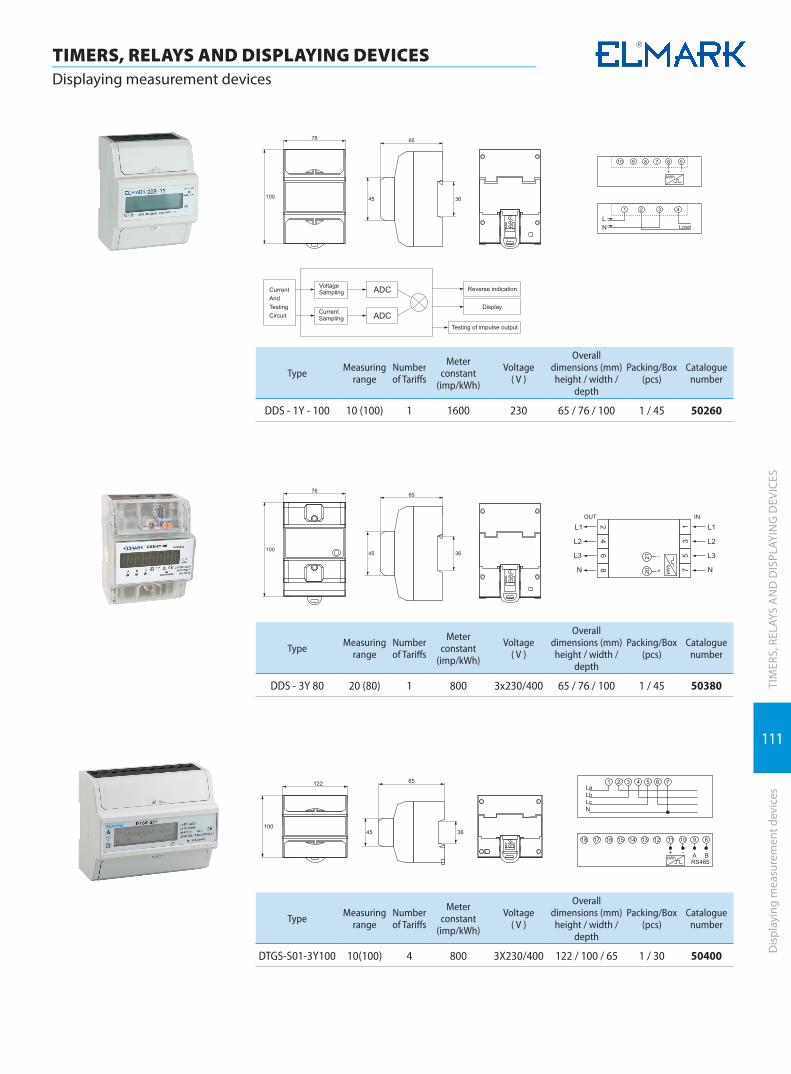
111
TIMERS, RELAYS AND DISPLAYING DEVICESDisplaying measurement devices
TIM
ERS,
REL
AYS
AN
D D
ISPL
AYIN
G D
EVIC
ESD
ispl
ayin
g m
easu
rem
ent d
evic
es
Type Measuring range
Number of Tariffs
Meter constant
(imp/kWh)
Voltage( V )
Overall dimensions (mm)height / width /
depth
Packing/Box (pcs)
Cataloguenumber
DDS - 1Y - 100 10 (100) 1 1600 230 65 / 76 / 100 1 / 45 50260
Type Measuring range
Number of Tariffs
Meter constant
(imp/kWh)
Voltage( V )
Overall dimensions (mm)height / width /
depth
Packing/Box (pcs)
Cataloguenumber
DDS - 3Y 80 20 (80) 1 800 3x230/400 65 / 76 / 100 1 / 45 50380
Type Measuring range
Number of Tariffs
Meter constant
(imp/kWh)
Voltage( V )
Overall dimensions (mm)height / width /
depth
Packing/Box (pcs)
Cataloguenumber
DTGS-S01-3Y100 10(100) 4 800 3X230/400 122 / 100 / 65 1 / 30 50400

ELEMENTSELEMENTS FOR AUTOMATION, MONITORING AND CONTROL

Limit switches | 114
Proximity sensor | 120
Capacitive sensor | 121
Photoelectrical sensor | 122
Power supplies | 123
Rotary switches | 124
Buttons and LED indicators | 128
Devices for telpher control | 133
Warning lights and towers | 134

114
ELEMENTS FOR AUTOMATION, MONITORING AND CONTROLLimit switches
ELEM
ENTS
FO
R A
UTO
MAT
ION
, MO
NIT
ORI
NG
AN
D C
ON
TRO
LLi
mit
switc
hes
TypeType of the
head
Power of starting
(g)
Power of release
(g)
Switch-ing
position
General move-ment
Rated current
Packing/Box (pcs)
Cataloguenumber
CSA - 001metal
cylinder800 400 2.0mm 5.8mm
10А-active4А-inductive
10 / 90 46А001
CSA - 003cylinder
with metal roll
800 400 2.0mm 5.8mm10А-active
4А-inductive10 / 90 46А003
CSA - 012horizontal lever with metal roll
800 400 2.0mm 5.8mm10А-active
4А-inductive10 / 90 46А012
CSA - 031adjustable lever with metal roll
400 100 22.5° 95°10А-active
4А-inductive10 / 80 46А031
CSA - 021lever with metal roll
400 100 22.5° 95°10А-active
4А-inductive10 / 80 46А021
CSA - 081 spring lever 150 50 22.5° 50mm10А-active
4А-inductive10 / 80 46А081
All-purpose limit switch – series CSA-xxx 3 YEAR WARRANTY
The all-purpose limit switches are devices used in automatic systems as a control element. They are used for setting of gearing limits. They are mounted on transport lines, conveyors and other linear progressive motion machines. They feature a vibration-resistant metal shell.
Product conformity documentation: � Standard: EN 60947-1; EN 60947-5-1 � Dielectric strength: 1000V AC � Insulating resistance: 100mΩ � Electrical endurance (number of cycles): 500 000
with active load � Mechanical endirance (number of cycles): 1 000 000 � Gearing speed: 5mm/s to 0.5 m/s
� Rated voltage: 230V � Rated current: up to 10A � IP code: IP66 � Cable input: cable glandPG11 � Section of power supply conductor: up to 2mm2
� Fastening strength of terminals: 6-8kgf/cm
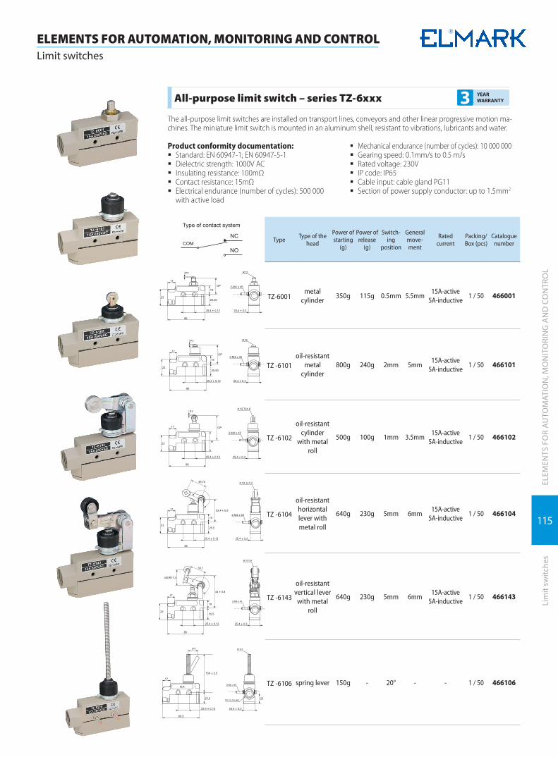
115
ELEMENTS FOR AUTOMATION, MONITORING AND CONTROLLimit switches
ELEM
ENTS
FO
R A
UTO
MAT
ION
, MO
NIT
ORI
NG
AN
D C
ON
TRO
LLi
mit
switc
hes
TypeType of the
head
Power of starting
(g)
Power of release
(g)
Switch-ing
position
General move-ment
Rated current
Packing/Box (pcs)
Cataloguenumber
TZ-6001metal
cylinder350g 115g 0.5mm 5.5mm
15А-active 5A-inductive
1 / 50 466001
TZ -6101oil-resistant
metal cylinder
800g 240g 2mm 5mm15А-active
5A-inductive1 / 50 466101
TZ -6102
oil-resistant cylinder
with metal roll
500g 100g 1mm 3.5mm15А-active
5A-inductive1 / 50 466102
TZ -6104
oil-resistant horizontal lever with metal roll
640g 230g 5mm 6mm15А-active
5A-inductive1 / 50 466104
TZ -6143
oil-resistant vertical lever with metal
roll
640g 230g 5mm 6mm15А-active
5A-inductive1 / 50 466143
TZ -6106 spring lever 150g - 20° - - 1 / 50 466106
All-purpose limit switch – series TZ-6xxx 3 YEAR WARRANTY
The all-purpose limit switches are installed on transport lines, conveyors and other linear progressive motion ma-chines. The miniature limit switch is mounted in an aluminum shell, resistant to vibrations, lubricants and water.
Product conformity documentation: � Standard: EN 60947-1; EN 60947-5-1 � Dielectric strength: 1000V AC � Insulating resistance: 100mΩ � Contact resistance: 15mΩ � Electrical endurance (number of cycles): 500 000
with active load
� Mechanical endurance (number of cycles): 10 000 000 � Gearing speed: 0.1mm/s to 0.5 m/s � Rated voltage: 230V � IP code: IP65 � Cable input: cable gland PG11 � Section of power supply conductor: up to 1.5mm2

116
ELEMENTS FOR AUTOMATION, MONITORING AND CONTROLLimit switches
ELEM
ENTS
FO
R A
UTO
MAT
ION
, MO
NIT
ORI
NG
AN
D C
ON
TRO
LLi
mit
switc
hes
TypeType of the
head
Power of starting
(g)
Power of release
(g)
Switch-ing
position
General move-ment
Rated current
Packing/Box (pcs)
Cataloguenumber
CM -1307Metal
cylinder350g 114g 0.4mm 5.5mm
15А-active 5A-inductive
1 / 480 468105
CM -1309Cylinder and
transverse metal roll
350g 114g 0.4mm 5.5mm15А-active
5A-inductive1 / 480 468106
СМ -1308Cylinder
longitudinal metal roll
350g 114g 0.4mm 5.5mm15А-active
5A-inductive1 / 480 468109
СМ -1305Metal
cylinder350g 114g 0.4mm 1.6mm
15А-active 5A-inductive
1 / 480 468110
CM -1703Extended metal roll
160g 22g 7.1mm 1.02mm15А-active
5A-inductive1 / 480 468113
CM -1705 Spring lever 10g 3g 20mm 5.6mm15А-active
5A-inductive1 / 480 468117
Universal Limit Switch – Series CM-1xxx 3 YEAR WARRANTY
Limit switches of the CM series are used mainly as replacement of the limit switches of the TZ series or for setting the movement limits of some types of equipment. The switches are supplied with screw cable terminals. They can work at resistance loads as high as 15A, and are of single circuit type. Limit switches have high accuracy and can operate at wide variety of speeds.
Items are compliant with the following stan-dards:EN 60947-1; EN 60947-5-1
� Dielectric Strength: 1000V AC � Insulation Resistance: 100mΩ min. (at 500VDC) � Contact Resistance: 5mΩ � Electrical Life (No. of cycles): 500 000 with non-
inductive load
� Mechanical Life (No. of cycles): 5 000 000 � Operating frequency: 20 electrical operations/
minute � Operating speed: 0.1mm/s to 1.0m/s � Rated voltage: 230V � IP code: IP65 � Fastening strength of terminals: 6-8kgf/cm

117
ELEMENTS FOR AUTOMATION, MONITORING AND CONTROLLimit switches
ELEM
ENTS
FO
R A
UTO
MAT
ION
, MO
NIT
ORI
NG
AN
D C
ON
TRO
LLi
mit
switc
hes
TypeType of the
head
Power of starting
(g)
Power of release
(g)
Switch-ing
position
General move-ment
Rated current
Packing/Box (pcs)
Cataloguenumber
TZ -8104lever with metal roll
750g 100g 20° 50°5А-active
3А-inductive10 / 100 468104
TZ -8108adjustable lever with metal roll
750g 100g 20° 50°5А-active
3А-inductive10 / 100 468108
TZ -8112cylinder
with metal roll
900g 150g 1.5mm 4.0mm5А-active
3А-inductive10 / 100 468112
TZ -8111metal
cylinder900g 150g 1.5mm 4.0mm
5А-active 3А-inductive
10 / 100 468111
TZ -8107 metal rod 750g 100g 20° 50°5А-active
3А-inductive10 / 100 468107
TZ -8167 spring lever 150g - 30mm -5А-active
3А-inductive10 / 100 468167
All-purpose limit switch – series TZ-8xxx 3 YEAR WARRANTY
The all-purpose limit switches are devices used for setting gearing limits. They are mounted on transport lines, con-veyors and other linear progressive motion machines. They have small dimensions and a vibration-resistant metal shell with plastic lid, resistant to oil and water.
Product conformity documentation: � Standard: EN 60947-1; EN 60947-5-1 � Dielectric strength: 1000V AC � Insulating resistance: 100MΩ � Contact Resistance: 25mΩ � Electrical endurance (number of cycles): 500 000
with active load
� Mechanical endurance (number of cycles): 5 000 000 � Gearing speed: 5mm/s to 0.5 m/s � Rated voltage: 230V � IP code: IP40 � Cable input: cable gland PG11 � Section of power supply conductor: up to 2mm � Fastening strength of terminals: 6-8kgf/cm
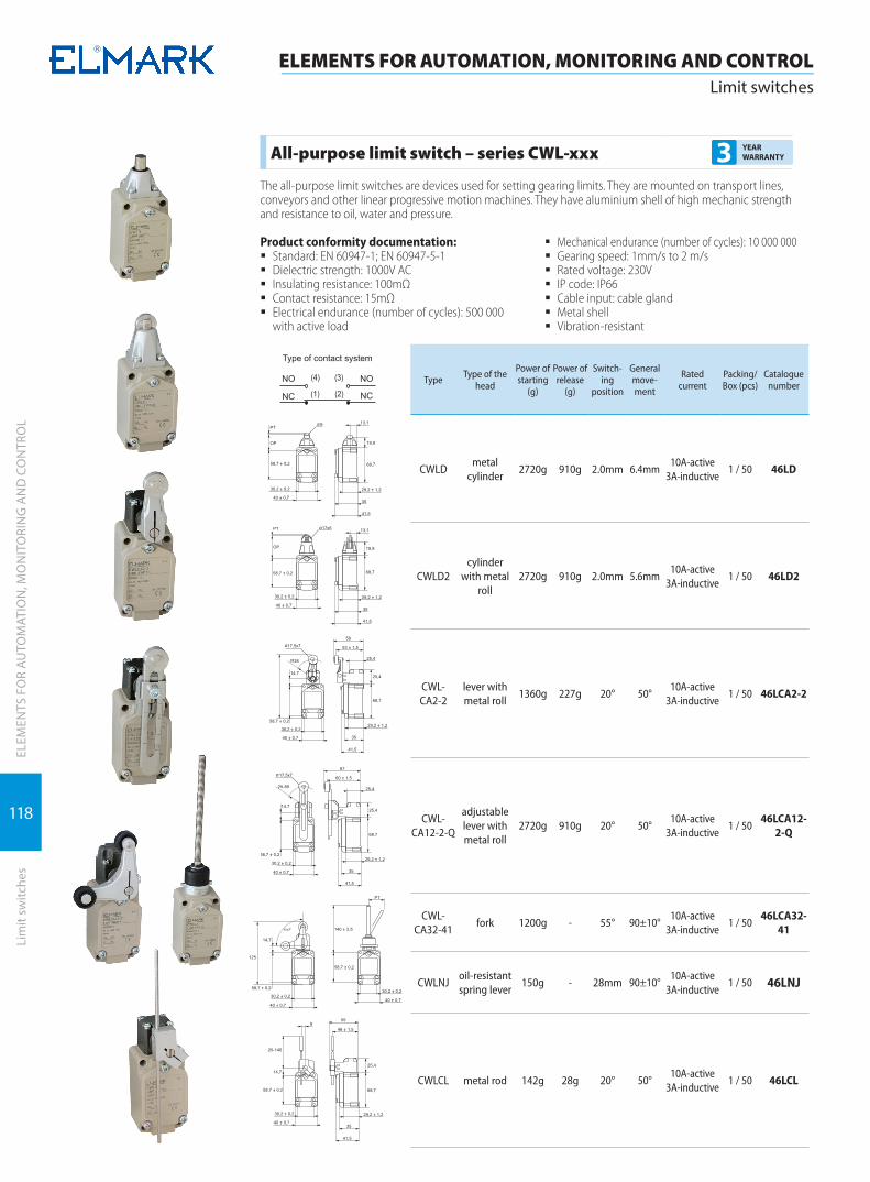
118
ELEMENTS FOR AUTOMATION, MONITORING AND CONTROLLimit switches
ELEM
ENTS
FO
R A
UTO
MAT
ION
, MO
NIT
ORI
NG
AN
D C
ON
TRO
LLi
mit
switc
hes
TypeType of the
head
Power of starting
(g)
Power of release
(g)
Switch-ing
position
General move-ment
Rated current
Packing/Box (pcs)
Cataloguenumber
CWLDmetal
cylinder2720g 910g 2.0mm 6.4mm
10А-active 3А-inductive
1 / 50 46LD
CWLD2cylinder
with metal roll
2720g 910g 2.0mm 5.6mm10А-active
3А-inductive1 / 50 46LD2
CWL-CA2-2
lever with metal roll
1360g 227g 20° 50°10А-active
3А-inductive1 / 50 46LCA2-2
CWL-CA12-2-Q
adjustable lever with metal roll
2720g 910g 20° 50°10А-active
3А-inductive1 / 50
46LCA12-2-Q
CWL-CA32-41
fork 1200g - 55° 90±10°10А-active
3А-inductive1 / 50
46LCA32-41
CWLNJoil-resistant spring lever
150g - 28mm 90±10°10А-active
3А-inductive1 / 50 46LNJ
CWLCL metal rod 142g 28g 20° 50°10А-active
3А-inductive1 / 50 46LCL
All-purpose limit switch – series CWL-xxx 3 YEAR WARRANTY
The all-purpose limit switches are devices used for setting gearing limits. They are mounted on transport lines, conveyors and other linear progressive motion machines. They have aluminium shell of high mechanic strength and resistance to oil, water and pressure.
Product conformity documentation: � Standard: EN 60947-1; EN 60947-5-1 � Dielectric strength: 1000V AC � Insulating resistance: 100mΩ � Contact resistance: 15mΩ � Electrical endurance (number of cycles): 500 000
with active load
� Mechanical endurance (number of cycles): 10 000 000 � Gearing speed: 1mm/s to 2 m/s � Rated voltage: 230V � IP code: IP66 � Cable input: cable gland � Metal shell � Vibration-resistant
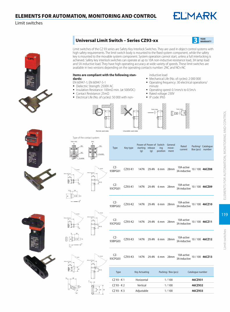
119
ELEMENTS FOR AUTOMATION, MONITORING AND CONTROLLimit switches
ELEM
ENTS
FO
R A
UTO
MAT
ION
, MO
NIT
ORI
NG
AN
D C
ON
TRO
LLi
mit
switc
hes
Type of the contact system
Type Key typePower of starting
(g)
Power of release
(g)
Switch-ing
position
General move-ment
Rated current
Packing/Box (pcs)
Cataloguenumber
CZ-93BPG01
CZ93-K1 147N 29.4N 6 mm 28mm10А-active
3А-inductive10 / 100 46CZ08
CZ-93CPG01
CZ93-K1 147N 29.4N 6 mm 28mm10А-active
3А-inductive10 / 100 46CZ09
CZ-93BPG02
CZ93-K2 147N 29.4N 6 mm 28mm10А-active
3А-inductive10 / 100 46CZ10
CZ-93CPG02
CZ93-K2 147N 29.4N 6 mm 28mm10А-active
3А-inductive10 / 100 46CZ11
CZ-93BPG03
CZ93-K3 147N 29.4N 6 mm 28mm10А-active
3А-inductive10 / 100 46CZ12
CZ-93CPG03
CZ93-K3 147N 29.4N 6 mm 28mm10А-active
3А-inductive10 / 100 46CZ13
Type Key Actuating Packing / Box (pcs) Catalogue number
CZ 93 - K 1 Horizontal 1 / 100 46CZ931
CZ 93 - K 2 Vertical 1 / 100 46CZ932
CZ 93 - K 3 Adjustable 1 / 100 46CZ933
Universal Limit Switch – Series CZ93-xx 3 YEAR WARRANTY
Limit switches of the CZ 93 series are Safety Key Interlock Switches. They are used in object control systems with high safety requirements. The limit switch body is mounted to the fixed system component, while the safety key is mounted to the movable system component. System operation cannot start, unless a full interlocking is achieved. Safety key interlock switches can operate at up to 10A non-inductive resistance load, 3A lamp load and 5A inductive load. They have high operating accuracy at wide variety of speeds. These limit switches are available in two versions depending on the operating contacts number: 2NC and NO+NC
Items are compliant with the following stan-dards:EN 60947-1; EN 60947-5-1
� Dielectric Strength: 2500V AC � Insulation Resistance: 100mΩ min. (at 500VDC) � Contact Resistance: 25mΩ � Electrical Life (No. of cycles): 50 000 with non-
inductive load � Mechanical Life (No. of cycles): 2 000 000 � Operating frequency: 30 electrical operations/
minute � Operating speed: 0.1mm/s to 0.5m/s � Rated voltage: 230V � IP code: IP65
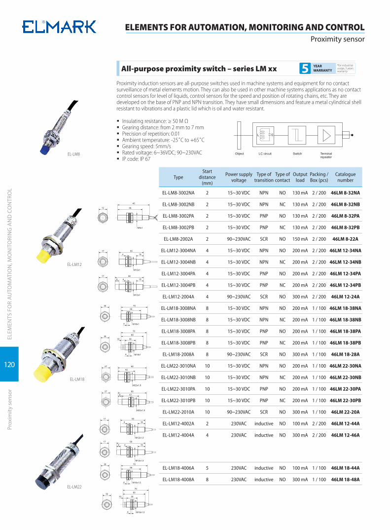
120
ELEM
ENTS
FO
R A
UTO
MAT
ION
, MO
NIT
ORI
NG
AN
D C
ON
TRO
L
ELEMENTS FOR AUTOMATION, MONITORING AND CONTROLProximity sensor
Prox
imity
sen
sor
TypeStart
distance (mm)
Power supply voltage
Type of transition
Type of contact
Output load
Packing / Box (pcs)
Catalogue number
EL-LM8-3002NA 2 15~30 VDC NPN NO 130 mA 2 / 200 46LM 8-32NA
EL-LM8-3002NB 2 15~30 VDC NPN NC 130 mA 2 / 200 46LM 8-32NB
EL-LM8-3002PA 2 15~30 VDC PNP NO 130 mA 2 / 200 46LM 8-32PA
EL-LM8-3002PB 2 15~30 VDC PNP NC 130 mA 2 / 200 46LM 8-32PB
EL-LM8-2002A 2 90~230VAC SCR NO 150 mA 2 / 200 46LM 8-22A
EL-LM12-3004NA 4 15~30 VDC NPN NO 200 mA 2 / 200 46LM 12-34NA
EL-LM12-3004NB 4 15~30 VDC NPN NC 200 mA 2 / 200 46LM 12-34NB
EL-LM12-3004PA 4 15~30 VDC PNP NO 200 mA 2 / 200 46LM 12-34PA
EL-LM12-3004PB 4 15~30 VDC PNP NC 200 mA 2 / 200 46LM 12-34PB
EL-LM12-2004A 4 90~230VAC SCR NO 300 mA 2 / 200 46LM 12-24A
EL-LM18-3008NA 8 15~30 VDC NPN NO 200 mA 1 / 100 46LM 18-38NA
EL-LM18-3008NB 8 15~30 VDC NPN NC 200 mA 1 / 100 46LM 18-38NB
EL-LM18-3008PA 8 15~30 VDC PNP NO 200 mA 1 / 100 46LM 18-38PA
EL-LM18-3008PB 8 15~30 VDC PNP NC 200 mA 1 / 100 46LM 18-38PB
EL-LM18-2008A 8 90~230VAC SCR NO 300 mA 1 / 100 46LM 18-28A
EL-LM22-3010NA 10 15~30 VDC NPN NO 200 mA 1 / 100 46LM 22-30NA
EL-LM22-3010NB 10 15~30 VDC NPN NC 200 mA 1 / 100 46LM 22-30NB
EL-LM22-3010PA 10 15~30 VDC PNP NO 200 mA 1 / 100 46LM 22-30PA
EL-LM22-3010PB 10 15~30 VDC PNP NC 200 mA 1 / 100 46LM 22-30PB
EL-LM22-2010A 10 90~230VAC SCR NO 300 mA 1 / 100 46LM 22-20A
EL-LM12-4002A 2 230VAC inductive NO 100 mA 2 / 200 46LM 12-44A
EL-LM12-4004A 4 230VAC inductive NO 300 mA 2 / 200 46LM 12-46A
EL-LM18-4006A 5 230VAC inductive NO 100 mA 1 / 100 46LM 18-44A
EL-LM18-4008A 8 230VAC inductive NO 300 mA 1 / 100 46LM 18-48A
All-purpose proximity switch – series LM xx*for industrial usage, 3 years warranty5 YEAR
WARRANTY
Proximity induction sensors are all-purpose switches used in machine systems and equipment for no contact surveillance of metal elements motion. They can also be used in other machine systems applications as no contact control sensors for level of liquids, control sensors for the speed and position of rotating chains, etc. They are developed on the base of PNP and NPN transition. They have small dimensions and feature a metal cylindrical shell resistant to vibrations and a plastic lid which is oil and water resistant.
� Insulating resistance: ≥ 50 M Ω � Gearing distance: from 2 mm to 7 mm � Precision of repetition: 0.01 � Ambient temperature: -25˚С to +65˚С � Gearing speed: 5mm/s � Rated voltage: 6~36VDC; 90~230VAC � IP code: IP 67
EL-LM8
EL-LM12
EL-LM18
EL-LM22

121
ELEM
ENTS
FO
R A
UTO
MAT
ION
, MO
NIT
ORI
NG
AN
D C
ON
TRO
LCa
paci
tive
sens
or
ELEMENTS FOR AUTOMATION, MONITORING AND CONTROLCapacitive sensor
EL-CM12
EL-CM18
EL-CM24
EL-SM12
EL-XM18
TypeStart
distance (mm)
Power sup-ply voltage
Type of transition
Type of contact
Output load
Packing / Box (pcs)
Catalogue number
EL-CM12-3004NA 0~4 15~30 VDC NPN NO 200 mA 1 / 100 46CM 12-32NA
EL-CM12-3004NB 0~4 15~30 VDC NPN NC 200 mA 1 / 100 46CM 12-32NB
EL-CM12-3004PA 0~4 15~30 VDC PNP NO 200 mA 1 / 100 46CM 12-32PA
EL-CM12-3004PB 0~4 15~30 VDC PNP NC 200 mA 1 / 100 46CM 12-32PB
EL-CM18-3008NA 0~8 15~30 VDC NPN NO 200 mA 1 / 100 46CM 18-38NA
EL-CM18-3008NB 0~8 15~30 VDC NPN NC 200 mA 1 / 100 46CM 18-38NB
EL-CM18-3008PA 0~8 15~30 VDC PNP NO 200 mA 1 / 100 46CM 18-38PA
EL-CM18-3008PB 0~8 15~30 VDC PNP NC 200 mA 1 / 100 46CM 18-38PB
EL-CM18-2008A 0~8 90~230VAC SCR NO 300 mA 1 / 100 46CM 18-28A
EL-CM24-3012NA 8 15~30 VDC NPN NO 200 mA 1 / 100 46CM 24-12NA
EL-CM24-3012NB 8 15~30 VDC NPN NC 200 mA 1 / 100 46CM 24-12NB
EL-CM24-3012PA 8 15~30 VDC PNP NO 200 mA 1 / 100 46CM 24-12PA
EL-CM24-3012PB 8 15~30 VDC PNP NC 200 mA 1 / 100 46CM 24-12PB
EL-CM24-2012A 8 90~230VAC SCR NO 300 mA 1 / 100 46CM 24-12A
EL-SM12-3110NA 10 15~30 VDC NPN NO 200 mA 2 / 200 46SM 12-31NA
EL-SM12-3110NB 10 15~30 VDC NPN NC 200 mA 2 / 200 46SM 12-31NB
EL-SM18-3110PA 10 15~30 VDC PNP NO 200 mA 1 / 100 46SM 18-31PA
EL-SM18-3110PB 10 15~30 VDC PNP NC 200 mA 1 / 100 46SM 18-31PB
EL-XM18-305PMI 5 15~30 VDC inductive NO 100 mA 1 / 100 46XM 18-35A
EL-XM18-305PMU 5 15~30 VDC inductive NC 100 mA 1 / 100 46XM 18-35B
Note: Sensor of Hall
EL-XM24-308PMI 8 15~30 VDC inductive NO 300 mA 1 / 100 46XM 24-38A
EL-XM24-308PMU 8 15~30 VDC inductive NC 300 mA 1 / 100 46XM 24-38B
Note: MI - current type; MU - voltage type
Capacitive sensors – series CM xx*for industrial usage, 3 years warranty5 YEAR
WARRANTY
Capacitive sensors are used in machine systems and equipment for no-contact motion surveillance. They consist of two coaxial electrodes, a condenser and RC generator. This type of sensors reacts to both metal and non-metal objects, as the gearing distance for non-metal objects depends on their dielectric constants. They allow gearing distance adjustment for non-magnetic conductive materials. They are developed on the base of PNP and NPN transition. They have small dimensions and feature a metal cylindrical shell resistant to vibrations and a plastic lid which is oil and water resistant.
� Insulating resistance: ≥ 50 M Ω � Gearing distance: from 2 mm to 15 mm � Precision of repetition: 0.01 � Ambient temperature: -25˚С to +65˚С � Gearing speed: 5mm/s � Rated voltage: 6~36VDC; 90~230VAC � IP code: IP 54
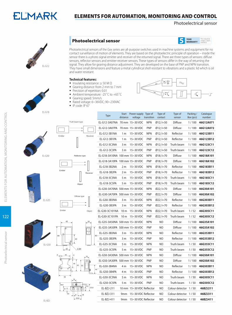
122
ELEM
ENTS
FO
R A
UTO
MAT
ION
, MO
NIT
ORI
NG
AN
D C
ON
TRO
L
ELEMENTS FOR AUTOMATION, MONITORING AND CONTROLPhotoelectrical sensor
Phot
oele
ctric
al s
enso
r
EL-G12
EL-G18
EL-G30
EL-G35
EL-G50
EL-BZJ
TypeStart
distancePower supply
voltageType of
transitionType of contact
Type ofsensor
Packing / Box (pcs)
Catalogue number
EL-G12-3A07NA 70 mm 15~30 VDC NPN Ø12; l=50 Diffuse 1 / 100 46G12A071
EL-G12-3A07PA 70 mm 15~30 VDC PNP Ø12; l=50 Diffuse 1 / 100 46G12A072
EL-G12-3B1NA 1 m 15~30 VDC NPN Ø12; l=50 Reflector 1 / 100 46G123B11
EL-G12-3B1PA 1 m 15~30 VDC PNP Ø12; l=50 Reflector 1 / 100 46G123B12
EL-G12-3C3NA 3 m 15~30 VDC NPN Ø12; l=50 Truth beam 1 / 100 46G123C11
EL-G12-3C3PA 3 m 15~30 VDC PNP Ø12; l=50 Truth beam 1 / 100 46G123C12
EL-G18-3A10NA 100 mm 15~30 VDC NPN Ø18; l=70 Diffuse 1 / 100 46G18A101
EL-G18-3A10PA 100 mm 15~30 VDC PNP Ø18; l=70 Diffuse 1 / 100 46G18A102
EL-G18-3B2NA 2 m 15~30 VDC NPN Ø18; l=70 Reflector 1 / 100 46G183B11
EL-G18-3B2PA 2 m 15~30 VDC PNP Ø18; l=70 Reflector 1 / 100 46G183B12
EL-G18-3C5NA 5 m 15~30 VDC NPN Ø18; l=70 Truth beam 1 / 100 46G185C11
EL-G18-3C5PA 5 m 15~30 VDC PNP Ø18; l=70 Truth beam 1 / 100 46G185C12
EL-G30-3A70NA 500 mm 15~30 VDC NPN Ø22; l=70 Diffuse 1 / 100 46G30A101
EL-G30-3A70PA 500 mm 15~30 VDC PNP Ø22; l=70 Diffuse 1 / 100 46G30A102
EL-G30-3B3NA 3 m 15~30 VDC NPN Ø22; l=70 Reflector 1 / 100 46G303B11
EL-G30-3B3PA 3 m 15~30 VDC PNP Ø22; l=70 Reflector 1 / 100 46G303B12
EL-G30-3C101NA 10 m 15~30 VDC NPN Ø22; l=70 Truth beam 1 / 52 46G305C11
EL-G30-3C101PA 10 m 15~30 VDC PNP Ø22; l=70 Truth beam 1 / 52 46G305C12
EL-G35-3A50NA 500 mm 15~30 VDC NPN NO Diffuse 1 / 100 46G35A101
EL-G35-3A50PA 500 mm 15~30 VDC PNP NO Diffuse 1 / 100 46G35A102
EL-G35-3B3NA 3 m 15~30 VDC NPN NO Reflector 1 / 100 46G353B11
EL-G35-3B3PA 3 m 15~30 VDC PNP NO Reflector 1 / 100 46G353B12
EL-G35-3C5NA 5 m 15~30 VDC NPN NO Truth beam 1 / 50 46G355C11
EL-G35-3C5PA 5 m 15~30 VDC PNP NO Truth beam 1 / 50 46G355C12
EL-G50-3A30NA 500 mm 15~30 VDC NPN NO Diffuse 1 / 100 46G50A101
EL-G50-3A30PA 500 mm 15~30 VDC PNP NO Diffuse 1 / 100 46G50A102
EL-G50-3B4NA 4 m 15~30 VDC NPN NO Reflector 1 / 100 46G503B11
EL-G50-3B4PA 4 m 15~30 VDC PNP NO Reflector 1 / 100 46G503B12
EL-G50-3C5NA 5 m 15~30 VDC NPN NO Truth beam 1 / 50 46G505C11
EL-G50-3C5PA 5 m 15~30 VDC PNP NO Truth beam 1 / 50 46G505C12
EL-BZJ-211 10 mm 15~30 VDC Reflector NO Colour detector 1 / 50 46BZJ211
EL-BZJ-311 9mm 15~30 VDC Reflector NO Colour detector 1 / 50 46BZJ311
EL-BZJ-411 9mm 15~30 VDC Reflector NO Colour detector 1 / 50 46BZJ411
Photoelectrical sensor*for industrial usage, 3 years warranty5 YEAR
WARRANTY
Photoelectrical sensors of the Gxx series are all-purpose switches used in machine systems and equipment for no contact surveillance of motion of elements. They are based on the photoelectric principle of operation – inside the sensor there is a photo signal emitter and receiver of the returned signal. There are three types of sensors: diffuse sensors, reflector sensors and emitter-receiver sensors. These types of sensors differ in the way of returning the signal. They allow for gearing distance adjustment. They are developed on the base of PNP and NPN transition. They have small dimensions and feature a metal cylindrical shell resistant to vibrations and a plastic lid which is oil and water resistant.
Technical features: � Insulating resistance: ≥ 50 M Ω � Gearing distance: from 2 mm to 7 mm � Precision of repetition: 0.01 � Ambient temperature: -25˚С to +65˚С � Gearing speed: 5mm/s � Rated voltage: 6~36VDC; 90~230VAC � IP code: IP 67
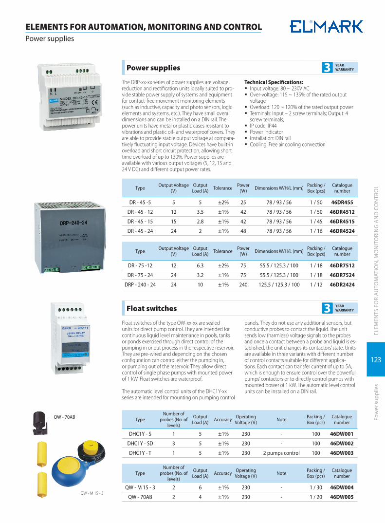
123
ELEM
ENTS
FO
R A
UTO
MAT
ION
, MO
NIT
ORI
NG
AN
D C
ON
TRO
LPo
wer
sup
plie
s
ELEMENTS FOR AUTOMATION, MONITORING AND CONTROLPower supplies
Power supplies 3 YEAR WARRANTY
The DRP-xx-xx series of power supplies are voltage reduction and rectification units ideally suited to pro-vide stable power supply of systems and equipment for contact-free movement monitoring elements (such as inductive, capacity and photo sensors, logic elements and systems, etc.). They have small overall dimensions and can be installed on a DIN rail. The power units have metal or plastic cases resistant to vibrations and plastic oil- and waterproof covers. They are able to provide stable output voltage at compara-tively fluctuating input voltage. Devices have built-in overload and short circuit protection, allowing short time overload of up to 130%. Power supplies are available with various output voltages (5, 12, 15 and 24 V DC) and different output power rates.
Technical Specifications: � Input voltage: 80 ~ 230V AC � Over-voltage: 115 ~ 135% of the rated output
voltage � Overload: 120 ~ 120% of the rated output power � Terminals: Input – 2 screw terminals; Output: 4
screw terminals; � IP code: IP44 � Power indicator � Installation: DIN rail � Cooling: Free air cooling convection
Type Output Voltage (V)
Output Load (A) Tolerance Power
(W) Dimensions W/H/L (mm) Packing / Box (pcs)
Catalogue number
DR - 45 -5 5 5 ±2% 25 78 / 93 / 56 1 / 50 46DR455
DR - 45 - 12 12 3.5 ±1% 42 78 / 93 / 56 1 / 50 46DR4512
DR - 45 - 15 15 2.8 ±1% 42 78 / 93 / 56 1 / 45 46DR4515
DR - 45 - 24 24 2 ±1% 48 78 / 93 / 56 1 / 16 46DR4524
Type Output Voltage (V)
Output Load (A) Tolerance Power
(W) Dimensions W/H/L (mm) Packing / Box (pcs)
Catalogue number
DR - 75 -12 12 6.3 ±2% 75 55.5 / 125.3 / 100 1 / 18 46DR7512
DR - 75 - 24 24 3.2 ±1% 75 55.5 / 125.3 / 100 1 / 18 46DR7524
DRP - 240 - 24 24 10 ±1% 240 125.5 / 125.3 / 100 1 / 12 46DR2424
Float switches 3 YEAR WARRANTY
Float switches of the type QW-xx-xx are sealed units for direct pump control. They are intended for continuous liquid level maintenance in pools, tanks or ponds exercised through direct control of the pumping in or out process in the respective reservoir. They are pre-wired and depending on the chosen configuration can control either the pumping in, or pumping out of the reservoir. They allow direct control of single phase pumps with mounted power of 1 kW. Float switches are waterproof.
The automatic level control units of the DHC1Y-xx series are intended for mounting on pumping control
panels. They do not use any additional sensors, but conductive probes to contact the liquid. The unit sends low (harmless) voltage signals to the probes and once a contact between a probe and liquid is es-tablished, the unit changes its contactors’ state. Units are available in three variants with different number of control contacts suitable for different applica-tions. Each contact can transfer current of up to 5A, which is enough to ensure control over the powerful pumps’ contactors or to directly control pumps with mounted power of 1 kW. The automatic level control units can be installed on a DIN rail.
QW - M 15 - 3
QW - 70AB TypeNumber of
probes (No. of levels)
Output Load (A) Accuracy Operating
Voltage (V) Note Packing / Box (pcs)
Catalogue number
DHC1Y - S 1 5 ±1% 230 - 100 46DW001
DHC1Y - SD 3 5 ±1% 230 - 100 46DW002
DHC1Y - T 1 5 ±1% 230 2 pumps control 100 46DW003
TypeNumber of
probes (No. of levels)
Output Load (A) Accuracy Operating
Voltage (V) Note Packing / Box (pcs)
Catalogue number
QW - M 15 - 3 2 6 ±1% 230 - 1 / 30 46DW004
QW - 70AB 2 4 ±1% 230 - 1 / 20 46DW005

124
ELEM
ENTS
FO
R A
UTO
MAT
ION
, MO
NIT
ORI
NG
AN
D C
ON
TRO
L
ELEMENTS FOR AUTOMATION, MONITORING AND CONTROLRotary switches
Rota
ry s
witc
hes
Rotary switches LW26 series*for industrial usage, 3 years warranty5 YEAR
WARRANTY
The rotary switches LW26 series are produced for switching on/off electrical circuits with commutated current from 20 to 160A. They are designed on the bases of the rotor-eccentric switching on which is realized through turning of the handle to 60 or 90 degrees. The normal operation is used for com-mutation of two, three or four conductor systems. There are special rotary switches that switch on under given connection schemes and are used to control motors, electric welding machines and other consumers.
Documentation corresponding to the product:Standard: EN 60947-1; EN 60947-3-1
Technical data: � Power supply voltage: 230/400V; 50Hz � Insulation voltage: 690V � Impulse voltage wear resistance: 6000V � Mechanical wear resistance: 3x10⁵ commutation
cycles � Operating temperature: -10 ÷ +65°C � Humidity: 35 – 85% RH � Commuting capacity: up to 160A according to
the tables � Plastic: UV rays wear resistance � IP code:
à IP42 for the ordinary breakers mounted in a panel
à IP65 for the breakers offered in a box � Cable connection: screw joining � Tightening moment of the bolt: 1.33N � Maximum section of the power supply conduc-
tors: according to the dimensions table � Weight: according to the number of the contacts
Mounting: � directly to the control panel � thickness of the surface to which it is mounted:
max 5mm
Dimensions Front panelJoining
conductor (mm2)
Overall dimensions (mm) Mounting dimensions (mm)
А B C L a b d1 d2
LW26-20 M1 panel 1x2.5 48 48 43 22 + 9.6n 36 36 Ø8.5 Ø4.5
M1 panel with inscription field
48 60 43 22 + 9.6n 36 36 Ø8.5 Ø4.5
LW26-25 M1 panel 1x4.0 48 48 45.2 23+12.8n 36 36 Ø8.5 Ø4.5
LW26-32 M2 panel 1x6.0 64 64 58 29.2 + 12.8n 48 48 Ø10 Ø4.5
LW26-63 M2 panel 1x16 64 64 66 29.2 + 21.5n 48 48 Ø10 Ø4.5
LW26-125 M3 panel 1x35 88 88 84 35 + 26.5n 68 68 Ø13 Ø6
LW26-160 M3 panel 1x50 88 88 88 35 + 32.5n 68 68 Ø13 Ø6
* n - number of modules
Type Scheme In (A) Levels Packing / Box (pcs) Catalogue number
LW26 - 10Q
Q10 three-poles switching on;
motor starting and stopping;voltage turning on/off to the
consumers
10 2 1 / 100 492101
LW26 - 16Q 16 2 1 / 100 492161LW26 - 20Q 20 2 1 / 100 492201LW26 - 25Q 25 2 1 / 100 492251LW26 - 32Q 32 2 1 / 72 492321LW26 - 63Q 63 2 1 / 64 492631
LW26 - 125Q 125 2 1 / 24 492951LW26 - 160Q 160 2 1 / 27 492961
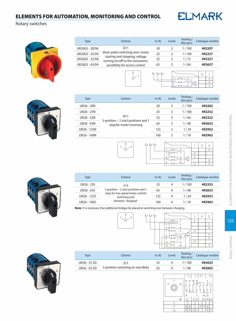
125
ELEM
ENTS
FO
R A
UTO
MAT
ION
, MO
NIT
ORI
NG
AN
D C
ON
TRO
LRo
tary
sw
itche
s
ELEMENTS FOR AUTOMATION, MONITORING AND CONTROLRotary switches
Type Scheme In (A) Levels Packing / Box (pcs) Catalogue number
LW26GS - 20/04 Q11 three-poles switching over; motor
starting and stopping; voltage turning on/off to the consumers;
possibility for access control
20 2 1 / 100 492207
LW26GS - 25/04 25 2 1 / 100 492257LW26GS - 32/04 32 2 1 / 72 492327
LW26GS - 63/04 63 2 1 / 64 492637
Type Scheme In (A) Levels Packing / Box (pcs) Catalogue number
LW26 - 20N
N113-position – 2 start positions and 1
stop;for motor reversing
20 3 1 / 100 492202
LW26 - 25N 25 3 1 / 100 492252
LW26 - 32N 32 3 1 / 64 492322
LW26 - 63N 63 3 1 / 48 492632
LW26 - 125N 125 3 1 / 24 492952
LW26 - 160N 160 3 1 / 18 492962
Type Scheme In (A) Levels Packing / Box (pcs) Catalogue number
LW26 - 25S S19 3-position – 2 start positions and 1 stop; for two speed motor control;
switching over between charging*
25 4 1 / 100 492253
LW26 - 63S 63 4 1 / 48 492633
LW26 - 125S 125 4 1 / 24 492953
LW26 - 160S 160 4 1 / 18 492963
Note: It is necessary that additional bridges be placed at switching over between charging
Type Scheme In (A) Levels Packing / Box (pcs) Catalogue number
LW26 - 25 SD S213-position switching on star/delta
25 4 1 / 100 492025
LW26 - 63 SD 63 4 1 / 48 492063
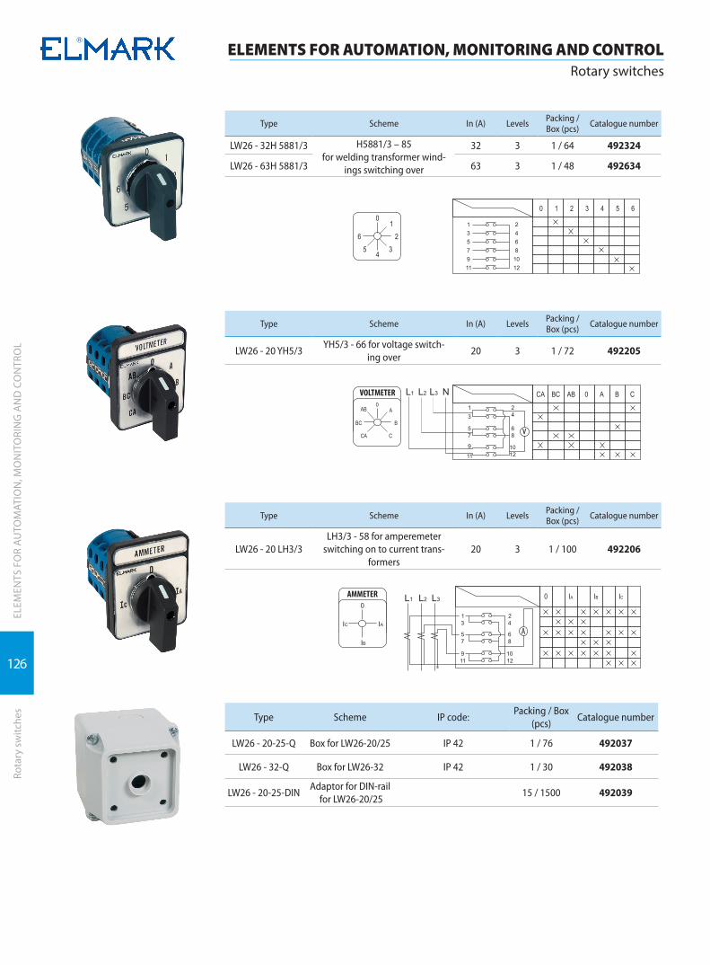
126
ELEM
ENTS
FO
R A
UTO
MAT
ION
, MO
NIT
ORI
NG
AN
D C
ON
TRO
L
ELEMENTS FOR AUTOMATION, MONITORING AND CONTROLRotary switches
Rota
ry s
witc
hes
Type Scheme In (A) Levels Packing / Box (pcs) Catalogue number
LW26 - 32H 5881/3 H5881/3 – 85 for welding transformer wind-
ings switching over
32 3 1 / 64 492324
LW26 - 63H 5881/3 63 3 1 / 48 492634
Type Scheme In (A) Levels Packing / Box (pcs) Catalogue number
LW26 - 20 YH5/3YH5/3 - 66 for voltage switch-
ing over20 3 1 / 72 492205
Type Scheme In (A) Levels Packing / Box (pcs) Catalogue number
LW26 - 20 LH3/3LH3/3 - 58 for amperemeter
switching on to current trans-formers
20 3 1 / 100 492206
Type Scheme IP code:Packing / Box
(pcs)Catalogue number
LW26 - 20-25-Q Box for LW26-20/25 IP 42 1 / 76 492037
LW26 - 32-Q Box for LW26-32 IP 42 1 / 30 492038
LW26 - 20-25-DINAdaptor for DIN-rail
for LW26-20/2515 / 1500 492039

127
ELEM
ENTS
FO
R A
UTO
MAT
ION
, MO
NIT
ORI
NG
AN
D C
ON
TRO
LRo
tary
sw
itche
s
ELEMENTS FOR AUTOMATION, MONITORING AND CONTROLRotary switches
Type Scheme In (A) Levels Packing / Box (pcs)
Catalogue number
LW26 4.I7168/7 4.I7168/7 20 7 1 / 100 492028
Type Scheme In (A) Levels Packing / Box (pcs)
Catalogue number
LW26 4.H6518/5
4.H6518/5 25 5 1 / 100 492029
Type Scheme In (A) Levels Packing / Box (pcs)
Catalogue number
LW30-20 LW30-20 20 3 1 / 32 492030
LW30-32 LW30-32 32 3 1 / 32 492031
LW30-40 LW30-40 40 3 1 / 32 492033
LW30-63 LW30-63 63 3 1 / 32 492034
* Possibility for access control
Type Scheme IP code: In (A) Levels Packing / Box (pcs)
Catalogue number
LW30-32 LW30-32 IP54 32 3 1 / 30 492032
* Possibility for access control

128
ELEM
ENTS
FO
R A
UTO
MAT
ION
, MO
NIT
ORI
NG
AN
D C
ON
TRO
L
ELEMENTS FOR AUTOMATION, MONITORING AND CONTROLButtons and LED indicators
Butt
ons
and
LED
indi
cato
rs
Buttons and LED indicators*for industrial usage, 3 years warranty5 YEAR
WARRANTY
These are devices used in control and indication systems, command boards and panels in industrial automation systems. They are manufactured to commutate controlling circuits and to control the switching on or off executive mechanisms such as relays, contactors, etc. The signal lamps and indica-tors find broad application in all industrial fields. The devices endure short time current overload up to 10A, and normally they can commutate thermal cur-rent up to 6A in their contact system. The connection to the contact terminals is through screw terminals to which operational conductors with section up to 2.5mm2 can be joined.
Documentation corresponding to the product: � Standard: EN 60947-1; EN 60947-5-1
Technical data: � Insulation voltage: 660V; 50/60Hz
� Impulse voltage wear resistance: 6000V; � Rated current: 6A (230V AC); 0.3A (230V DC) � Short circuit protection: safety device 10A gG
outside in the circuit � Mechanical wear resistance: 1x10⁶ commutation
cycles � Power of mechanical compression:
à at closing: 20N à at opening: 8N
� Operating temperature: -20 - +65°C � Humidity: 35 – 85%RH � Tightening moment of the joining conductors:
0.15Nm � Section of the conductor: 1x0.5; 1x0.75; 1x1; 1x1.5;
1x2.5mm2
Mounting: � to a flat metal or plastic surface with thickness:
max 4mm � opening with size: Ø 22.5mm
Type Description Type of contacts
Rated cur-rent (А) at
400VColour Packing / Box
(pcs)Catalogue
number
EL 2- BA 21
Button round with spring reverse
NO 6 black 20 / 300 401021
EL 2- BA 31 NO 6 green 20 / 300 401031
EL 2- BA 51 NO 6 yellow 20 / 300 401051
EL 2- BA 61 NO 6 blue 20 / 300 401061
EL 2- BA 42 NC 6 red 20 / 300 401042
Type Description Type of contacts
Rated cur-rent (А) at
400VColour Note Packing /
Box (pcs)Catalogue
number
EL 2- BР 31 Button round with spring
reverse
NO 6 greenIP=65 Provided from
silicon lid20 / 300 401032
EL 2- BР 42 NC 6 red IP=65 Provided from
silicon lid20 / 300 401043
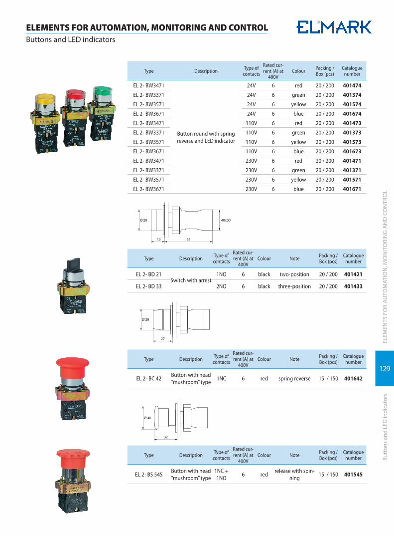
129
ELEM
ENTS
FO
R A
UTO
MAT
ION
, MO
NIT
ORI
NG
AN
D C
ON
TRO
LBu
tton
s an
d LE
D in
dica
tors
ELEMENTS FOR AUTOMATION, MONITORING AND CONTROLButtons and LED indicators
Type Description Type of contacts
Rated cur-rent (А) at
400VColour Packing /
Box (pcs)Catalogue
number
EL 2- BW3471
Button round with spring reverse and LED indicator
24V 6 red 20 / 200 401474
EL 2- BW3371 24V 6 green 20 / 200 401374
EL 2- BW3571 24V 6 yellow 20 / 200 401574
EL 2- BW3671 24V 6 blue 20 / 200 401674
EL 2- BW3471 110V 6 red 20 / 200 401473
EL 2- BW3371 110V 6 green 20 / 200 401373
EL 2- BW3571 110V 6 yellow 20 / 200 401573
EL 2- BW3671 110V 6 blue 20 / 200 401673
EL 2- BW3471 230V 6 red 20 / 200 401471
EL 2- BW3371 230V 6 green 20 / 200 401371
EL 2- BW3571 230V 6 yellow 20 / 200 401571
EL 2- BW3671 230V 6 blue 20 / 200 401671
Type Description Type of contacts
Rated cur-rent (А) at
400VColour Note Packing /
Box (pcs)Catalogue
number
EL 2- BD 21Switch with arrest
1NO 6 black two-position 20 / 200 401421
EL 2- BD 33 2NО 6 black three-position 20 / 200 401433
Type Description Type of contacts
Rated cur-rent (А) at
400VColour Note Packing /
Box (pcs)Catalogue
number
EL 2- BС 42Button with head “mushroom” type
1NС 6 red spring reverse 15 / 150 401642
Type Description Type of contacts
Rated cur-rent (А) at
400VColour Note Packing /
Box (pcs)Catalogue
number
EL 2- BS 545Button with head “mushroom” type
1NС + 1NO
6 redrelease with spin-
ning15 / 150 401545

130
ELEM
ENTS
FO
R A
UTO
MAT
ION
, MO
NIT
ORI
NG
AN
D C
ON
TRO
L
ELEMENTS FOR AUTOMATION, MONITORING AND CONTROLButtons and LED indicators
Butt
ons
and
LED
indi
cato
rs
Type Description Type of contacts
Rated current (А)
at 400V
Voltage (V) Note Packing /
Box (pcs)Catalogue
number
EL 2- BW8475Button double
1NO+1NС 6 24 ACGreen and red button
+ LED indicator20 / 200 401844
EL 2-BW8475Button double
1NO+1NC 6 230 ACGreen and red
button+LED indicator20/200 401845
Type Description Type of contacts
Rated cur-rent (А) at
400VNote Packing /
Box (pcs)Catalogue
number
EL 2- BG 21Change-over switch
with switch1NO 6
two-position with switch
20 / 200 401121
Type Description Rated current (А) at 400V Colour Packing / Box (pcs)
Catalogue number
AD56-22-W-230
LED indicators
230V AC white 10 / 500 401123
AD56-22-W-110 110V AC white 10 / 500 401111
AD56-22-W-24 24V AC/DC white 10 / 500 401124
AD56-22-А-110 110V AC amber 10 / 500 401211
AD56-22-А-24 24V AC/DC amber 10 / 500 401224
AD56-22-А-230 230V AC amber 10 / 500 401223
AD56-22-РG-230 230V AC green 10 / 500 401323
AD56-22-РG-110 110V AC green 10 / 500 401311
AD56-22-РG-24 24V AC/DC green 10 / 500 401324
AD56-22-B-230 230V AC blue 10 / 500 401523
AD56-22-B-110 110V AC blue 10 / 500 401511
AD56-22-B-24 24V AC/DC blue 10 / 500 401524
AD56-22-Y-230 230V AC yellow 10 / 500 401723
AD56-22-Y-110 110V AC yellow 10 / 500 401711
AD56-22-Y-24 24V AC/DC yellow 10 / 500 401724
AD56-22-R-230 230V AC red 10 / 500 401423
AD56-22-R-110 110V AC red 10 / 500 401411
AD56-22-R-24 24V AC/DC red 10 / 500 401424
Type Description Type of contacts Colour Packing / Box (pcs) Catalogue number
EL02 - BЕ101 1 1 NO green 100 / 1000 401001
EL02 - BЕ102 2 1 NC red 100 / 1000 401002

131
ELEM
ENTS
FO
R A
UTO
MAT
ION
, MO
NIT
ORI
NG
AN
D C
ON
TRO
LBu
tton
s an
d LE
D in
dica
tors
ELEMENTS FOR AUTOMATION, MONITORING AND CONTROLButtons and LED indicators
Buttons and switches with box 3 YEAR WARRANTY
Type Description IP code: Overall dimensions
(mm)Type
of the contact
Colour Packing / Box (pcs)
Catalogue number
L H W
EL1-B134 switching on 0-1 IP44 68 68 50 1 NO black 1 / 100 401134
Type Description IP code: Overall dimensions
(mm)Type
of the contact
Colour Packing / Box (pcs)
Catalogue number
L H W
EL1-B1021 button with spring return
IP44 68 68 50 1 NO green 1 / 100 401102
EL1-BP1021 button with spring return
IP65 68 68 50 1 NO green 1 / 100 401132
Type Description IP code: Overall dimensions
(mm)Type
of the contact
Colour Packing / Box (pcs)
Catalogue number
L H W
EL1-B2132 buttons with spring return
IP44 104 68 501 NC 1 NO
1 - red 1 - green
1 / 100 401213
EL1-BP2132 buttons with spring return
IP65 104 68 501 NC 1 NO
1 - red 1 - green
1 / 100 401233
Type Description IP code: Overall dimensions
(mm)Type
of the contact
Colour Packing / Box (pcs)
Catalogue number
L H W
EL1-B3393 buttons with spring return
IP44 134 68 501 NO 1 NC 1 NO
1 - green 1 - red
1 - green1 / 50 401339
EL1-BP3393 buttons with spring return
IP65 134 68 501 NO 1 NC 1 NO
1 - green 1 - red
1 - green1 / 50 401349
Type Description IP code: Overall dimensions
(mm)Type
of the contact
Colour Packing / Box (pcs)
Catalogue number
L H W
EL1-B174
Emergency but-ton with head “mushroom”
type Ø40.Release through turning
IP44 68 68 50 1 NC red 1 / 100 401174

132
ELEM
ENTS
FO
R A
UTO
MAT
ION
, MO
NIT
ORI
NG
AN
D C
ON
TRO
L
ELEMENTS FOR AUTOMATION, MONITORING AND CONTROLButtons and LED indicators
Butt
ons
and
LED
indi
cato
rs
Buttons and LED indicators*for industrial usage, 3 years warranty5 YEAR
WARRANTY
These are devices used in control and indication sys-tems adjusted for mounting in command boards and panels directly on DIN-rail. They are manufactured to commutate controlling circuits and to control the switching on or off executive mechanisms such as relays, contactors, etc. The signal lamps and indica-tors find broad application in all industrial fields. The devices endure short time current overload up to 20A, and normally they can commutate current up to 10A with their contact system. The connection to the contact terminals is through screw terminals to which operational conductors with section up to 2.5mm2 can be joined. There are also designed but-tons combined with lamps.
Technical data: � Insulation voltage: 660V; 50/60Hz � Impulse voltage wear resistance: 6000V; � Rated current: up to 10A (230V AC)
� Short circuit protection: safety device 10A gG outside in the circuit
� Rated consumed current (for indicators and but-tons combined with indicators): <20mA
� wear resistance (indicators): >2000h � Mechanical wear resistance (buttons): 1x10⁶ com-
mutation cycles � Power of mechanical compression:
à at closing: 20N à at opening: 8N
� Operating temperature: -20 - +65°C � Humidity: 35 – 85%RH � Tightening moment of the joining conductors:
0.15Nm � Section of the conductor: 1x0.5; 1x0.75; 1x1; 1x1.5;
1x2.5mm2
� Plastic: UV rays wear resistance Mounting:
� to a DIN-rail � Altitude: up to 2000m
Documents corresponding to the product:Standard EN 60947-1EN 60 947-5-1 t
Type DescriptionRated cur-
rent (A) at 400V
Type of the contact Colour Packing / Box (pcs) Catalogue number
ELB - BL - DIN button <10 2NO+ 1 NC black 12 / 240 401505
ELB - BL - DIN button <10 1NO+ 2 NC black 12 / 240 401506
ELB - G - DIN button <10 2NO+ 1 NC green 12 / 240 401507
ELB - G -DIN button <10 1NO+ 2 NC green 12 / 240 401508
ELB - Y - DIN button <10 2NO+ 1 NC yellow 12 / 240 401509
ELB - Y - DIN button <10 1NO+ 2 NC yellow 12 / 240 401510
ELB - R - DIN button <10 2NO+ 1 NC red 12 / 240 401512
ELB - R - DIN button <10 1NO+ 2 NC red 12 / 240 401513
Type Description Voltage (V) Rated current (A) at 400V Colour Packing / Box
(pcs) Catalogue number
ELD - G - DIN lamp 230V <20 green 12 / 240 401500
ELD - R - DIN lamp 230V <20 red 12 / 240 401501
ELD - Y - DIN lamp 230V <20 yellow 12 / 240 401502
ELD - B - DIN lamp 230V <20 blue 12 / 240 401503
ELD -W - DIN lamp 230V <20 white 12 / 240 401504
Type Description Voltage (V)
Rated cur-rent
(A) at 400V
Type of the contact Colour Packing / Box
(pcs)Catalogue
number
ELBD - G - DIN button + lamp 230V <20 2NO+ 1 NC green 12 / 240 401514
ELBD -G - DIN button + lamp 230V <20 1NO+ 2 NC green 12 / 240 401515
ELBD - R - DIN button + lamp 230V <20 2NO+ 1 NC red 12 / 240 401516
ELBD - R - DIN button + lamp 230V <20 1NO+ 2 NC red 12 / 240 401517
ELBD - Y - DIN button + lamp 230V <20 2NO+ 1 NC yellow 12 / 240 401518
ELBD - Y - DIN button + lamp 230V <20 1NO+ 2 NC yellow 12 / 240 401519
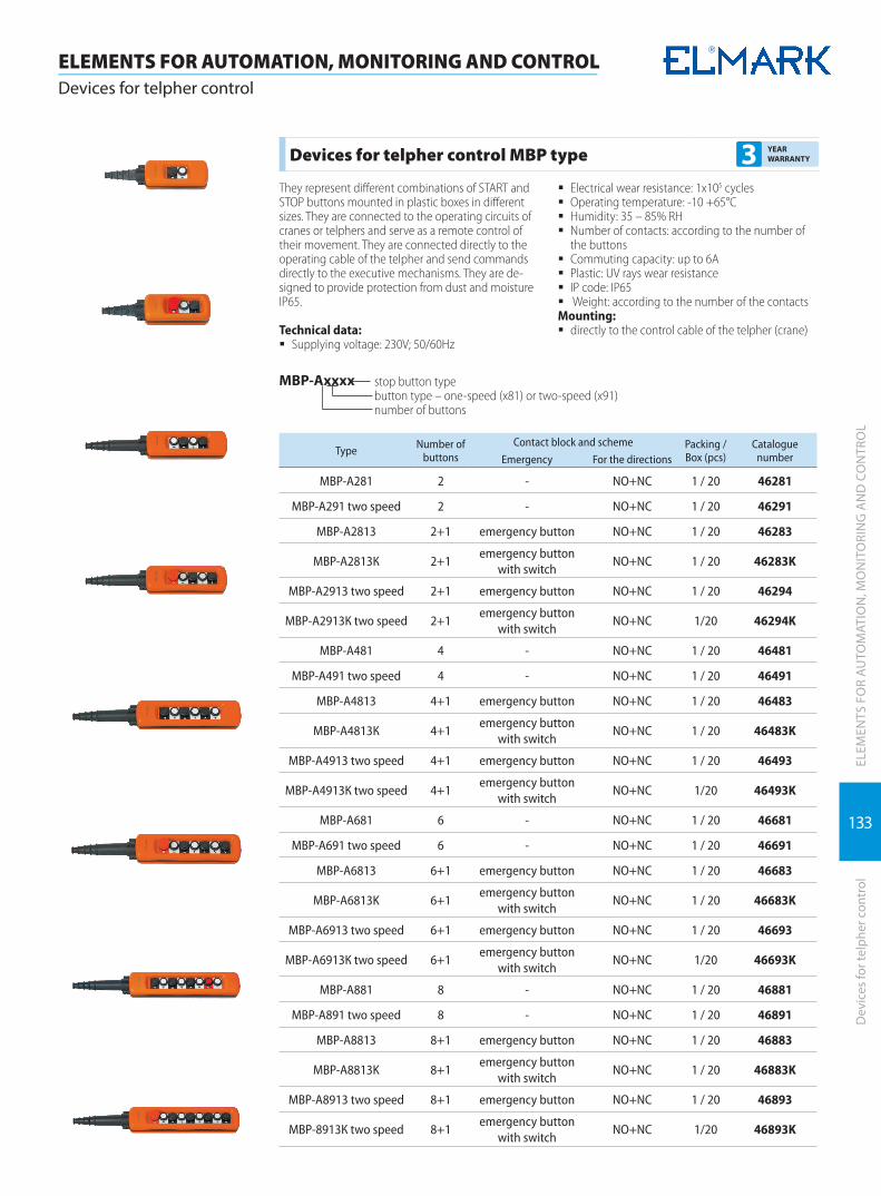
133
ELEM
ENTS
FO
R A
UTO
MAT
ION
, MO
NIT
ORI
NG
AN
D C
ON
TRO
LD
evic
es fo
r tel
pher
con
trol
ELEMENTS FOR AUTOMATION, MONITORING AND CONTROLDevices for telpher control
Devices for telpher control MBP type 3 YEAR WARRANTY
They represent different combinations of START and STOP buttons mounted in plastic boxes in different sizes. They are connected to the operating circuits of cranes or telphers and serve as a remote control of their movement. They are connected directly to the operating cable of the telpher and send commands directly to the executive mechanisms. They are de-signed to provide protection from dust and moisture IP65.
Technical data: � Supplying voltage: 230V; 50/60Hz
� Electrical wear resistance: 1x10⁵ cycles � Operating temperature: -10 +65°C � Humidity: 35 – 85% RH � Number of contacts: according to the number of
the buttons � Commuting capacity: up to 6A � Plastic: UV rays wear resistance � IP code: IP65 � Weight: according to the number of the contacts
Mounting: � directly to the control cable of the telpher (crane)
МВР-Ахххх stop button typebutton type – one-speed (x81) or two-speed (x91)number of buttons
Type Number of buttons
Contact block and scheme Packing / Box (pcs)
Catalogue numberEmergency For the directions
MBP-A281 2 - NO+NC 1 / 20 46281
MBP-A291 two speed 2 - NO+NC 1 / 20 46291
MBP-A2813 2+1 emergency button NO+NC 1 / 20 46283
MBP-A2813К 2+1emergency button
with switchNO+NC 1 / 20 46283K
MBP-A2913 two speed 2+1 emergency button NO+NC 1 / 20 46294
МВР-А2913К two speed 2+1emergency button
with switchNO+NC 1/20 46294K
MBP-A481 4 - NO+NC 1 / 20 46481
MBP-A491 two speed 4 - NO+NC 1 / 20 46491
MBP-A4813 4+1 emergency button NO+NC 1 / 20 46483
MBP-A4813К 4+1emergency button
with switchNO+NC 1 / 20 46483K
MBP-A4913 two speed 4+1 emergency button NO+NC 1 / 20 46493
МВР-А4913К two speed 4+1emergency button
with switchNO+NC 1/20 46493K
MBP-A681 6 - NO+NC 1 / 20 46681
MBP-A691 two speed 6 - NO+NC 1 / 20 46691
MBP-A6813 6+1 emergency button NO+NC 1 / 20 46683
MBP-A6813K 6+1emergency button
with switchNO+NC 1 / 20 46683K
MBP-A6913 two speed 6+1 emergency button NO+NC 1 / 20 46693
МВР-А6913К two speed 6+1emergency button
with switchNO+NC 1/20 46693K
MBP-A881 8 - NO+NC 1 / 20 46881
MBP-A891 two speed 8 - NO+NC 1 / 20 46891
MBP-A8813 8+1 emergency button NO+NC 1 / 20 46883
MBP-A8813K 8+1emergency button
with switchNO+NC 1 / 20 46883K
MBP-A8913 two speed 8+1 emergency button NO+NC 1 / 20 46893
МВР-8913К two speed 8+1emergency button
with switchNO+NC 1/20 46893K
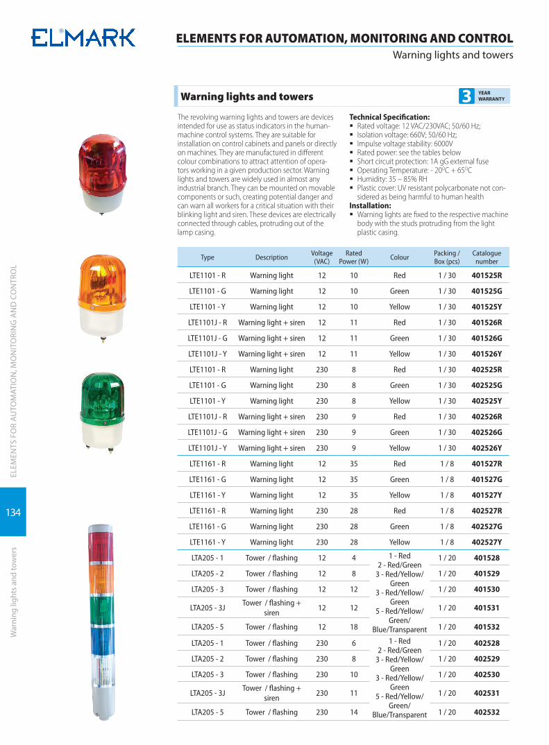
134
ELEM
ENTS
FO
R A
UTO
MAT
ION
, MO
NIT
ORI
NG
AN
D C
ON
TRO
L
ELEMENTS FOR AUTOMATION, MONITORING AND CONTROLWarning lights and towers
War
ning
ligh
ts a
nd to
wer
s
Warning lights and towers 3 YEAR WARRANTY
The revolving warning lights and towers are devices intended for use as status indicators in the human-machine control systems. They are suitable for installation on control cabinets and panels or directly on machines. They are manufactured in different colour combinations to attract attention of opera-tors working in a given production sector. Warning lights and towers are widely used in almost any industrial branch. They can be mounted on movable components or such, creating potential danger and can warn all workers for a critical situation with their blinking light and siren. These devices are electrically connected through cables, protruding out of the lamp casing.
Technical Specification: � Rated voltage: 12 VAC/230VAC; 50/60 Hz; � Isolation voltage: 660V; 50/60 Hz; � Impulse voltage stability: 6000V � Rated power: see the tables below � Short circuit protection: 1A gG external fuse � Operating Temperature: - 20OC + 65OC � Humidity: 35 – 85% RH � Plastic cover: UV resistant polycarbonate not con-
sidered as being harmful to human healthInstallation:
� Warning lights are fixed to the respective machine body with the studs protruding from the light plastic casing.
Type Description Voltage (VAC)
Rated Power (W) Colour Packing /
Box (pcs)Catalogue
number
LTE1101 - R Warning light 12 10 Red 1 / 30 401525R
LTE1101 - G Warning light 12 10 Green 1 / 30 401525G
LTE1101 - Y Warning light 12 10 Yellow 1 / 30 401525Y
LTE1101J - R Warning light + siren 12 11 Red 1 / 30 401526R
LTE1101J - G Warning light + siren 12 11 Green 1 / 30 401526G
LTE1101J - Y Warning light + siren 12 11 Yellow 1 / 30 401526Y
LTE1101 - R Warning light 230 8 Red 1 / 30 402525R
LTE1101 - G Warning light 230 8 Green 1 / 30 402525G
LTE1101 - Y Warning light 230 8 Yellow 1 / 30 402525Y
LTE1101J - R Warning light + siren 230 9 Red 1 / 30 402526R
LTE1101J - G Warning light + siren 230 9 Green 1 / 30 402526G
LTE1101J - Y Warning light + siren 230 9 Yellow 1 / 30 402526Y
LTE1161 - R Warning light 12 35 Red 1 / 8 401527R
LTE1161 - G Warning light 12 35 Green 1 / 8 401527G
LTE1161 - Y Warning light 12 35 Yellow 1 / 8 401527Y
LTE1161 - R Warning light 230 28 Red 1 / 8 402527R
LTE1161 - G Warning light 230 28 Green 1 / 8 402527G
LTE1161 - Y Warning light 230 28 Yellow 1 / 8 402527Y
LTA205 - 1 Tower / flashing 12 4 1 - Red2 - Red/Green
3 - Red/Yellow/Green
3 - Red/Yellow/Green
5 - Red/Yellow/Green/
Blue/Transparent
1 / 20 401528
LTA205 - 2 Tower / flashing 12 8 1 / 20 401529
LTA205 - 3 Tower / flashing 12 12 1 / 20 401530
LTA205 - 3JTower / flashing +
siren12 12 1 / 20 401531
LTA205 - 5 Tower / flashing 12 18 1 / 20 401532
LTA205 - 1 Tower / flashing 230 6 1 - Red2 - Red/Green
3 - Red/Yellow/Green
3 - Red/Yellow/Green
5 - Red/Yellow/Green/
Blue/Transparent
1 / 20 402528
LTA205 - 2 Tower / flashing 230 8 1 / 20 402529
LTA205 - 3 Tower / flashing 230 10 1 / 20 402530
LTA205 - 3JTower / flashing +
siren230 11 1 / 20 402531
LTA205 - 5 Tower / flashing 230 14 1 / 20 402532

135
ELEM
ENTS
FO
R A
UTO
MAT
ION
, MO
NIT
ORI
NG
AN
D C
ON
TRO
LW
arni
ng li
ghts
and
tow
ers
ELEMENTS FOR AUTOMATION, MONITORING AND CONTROLWarning lights and towers
Type Description Voltage (V)
Rated Power
(W)Sound level (dB) Packing /
Box (pcs)Catalogue
number
MS-290A metal siren 230 60 100 1 / 24 401533
MS-290B plastic siren 230 60 100 1 / 10 401541
Type Description Voltage (V)
Rated Power
(W)Sound level (dB) Packing /
Box (pcs)Catalogue
number
MS-390 siren 230 160 120 1 / 50 401534
Type Description Voltage (V)
Rated Power
(W)Sound level (dB) Packing /
Box (pcs)Catalogue
number
CB-4 alarm bell 12 - 85 1 / 50 401535
CB-4 alarm bell 24 - 85 1 / 50 401536
CB-4 alarm bell 110 - 85 1 / 50 401537
CB-4 alarm bell 230 - 85 1 / 50 401538
Type Description Voltage (V)
Rated Power
(W)Sound level (dB) Packing /
Box (pcs)Catalogue
number
FA-01 fire alarm 230 - - 1 / 50 401540

INDUSTRIALPLUGS AND SOCKETS
INDUSTRIAL PLUGS AND SOCKETS
Industrial plugs | 138
Industrial sockets | 139

138
INDUSTRIAL PLUG AND SOCKETSIndustrial plugs
IND
UST
RIA
L PL
UG
AN
D S
OCK
ETS
Indu
stria
l plu
gs
Industrial plugs and sockets HT/HTN type 5 YEAR WARRANTY
Made of special high quality plastic with alloys against aging at sun light exposing and for increasing the me-chanical strength. They are designed in accordance with standard EN 60309 and provide reliable connection and high protection level against electrical current. They provide IP protection not less than IP 44/67. They are designed for surface or flush mounting, movable or fixed type.
Technical data: � Rated voltage: 500V � Rated short circuit current: according to the mounted protection in the boards � Impulse voltage wear resistance: 8kV � Mechanical wear resistance: 3000 cycles � IP code: IP 44/67 � Plastic: UV rays wear resistance � Ambient temperature: -5 to +65°C � Altitude: up to 2000m � Plugs and sockets: 6h
Documents corresponding to the product: Standard EN 60309-1; EN 60309-2
Model In (A) Poles Un (V) Dimensions (mm)A /B /C IP code: Packing/Box Catalogue
number
HT-013 16 1P+N+E 230 121 / 84 / 53 44 2 / 10 / 100 37013
HT-023 32 1P+N+E 230 138 / 92 / 63 44 2 / 10 / 60 37023
Model In (A) Poles Un (V) Dimensions (mm)A /B /C IP code: Packing/Box Catalogue
number
HT-014 16 3P+E 400 121 / 84 / 51 44 2 / 10 / 100 37014
HT-024 32 3P+E 400 138 / 92 / 63 44 2 / 10 / 60 37024
HT-034 63 3P+E 400 230 / 109 / 36 44 2 / 10 37034
HT-044 125 3P+E 400 295 / 124 / 50 44 2 / 10 37044
Model In (A) Poles Un (V) Dimensions (mm)A /B /C IP code: Packing/Box Catalogue
number
HT-015 16 3P+N+E 400 129 / 92 / 62 44 2 / 10 / 60 37015
HT-025 32 3P+N+E 400 149 / 97 / 70 44 2 / 10 / 60 37025
HT-035 63 3P+N+E 400 230 / 109 / 36 44 2 / 10 37035
HT-045 125 3P+N+E 400 295 / 124 / 50 44 2 / 10 37045
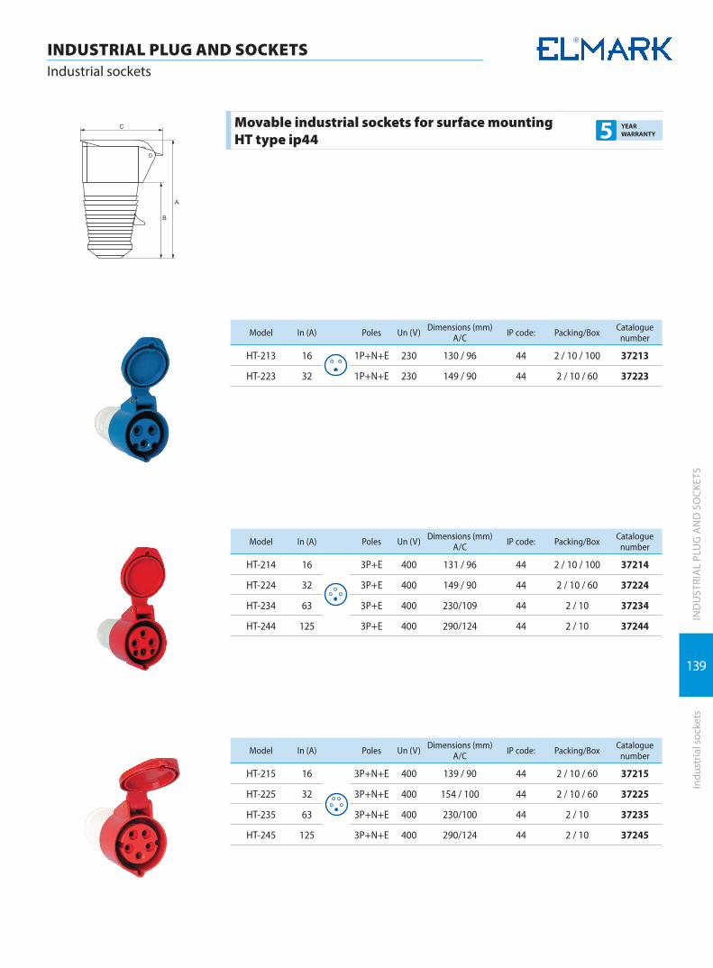
139
IND
UST
RIA
L PL
UG
AN
D S
OCK
ETS
Indu
stria
l soc
kets
INDUSTRIAL PLUG AND SOCKETSIndustrial sockets
Movable industrial sockets for surface mounting HT type ip44 5 YEAR
WARRANTY
Model In (A) Poles Un (V) Dimensions (mm)A/C IP code: Packing/Box Catalogue
number
HT-213 16 1P+N+E 230 130 / 96 44 2 / 10 / 100 37213
HT-223 32 1P+N+E 230 149 / 90 44 2 / 10 / 60 37223
Model In (A) Poles Un (V) Dimensions (mm)A/C IP code: Packing/Box Catalogue
number
HT-214 16 3P+E 400 131 / 96 44 2 / 10 / 100 37214
HT-224 32 3P+E 400 149 / 90 44 2 / 10 / 60 37224
HT-234 63 3P+E 400 230/109 44 2 / 10 37234
HT-244 125 3P+E 400 290/124 44 2 / 10 37244
Model In (A) Poles Un (V) Dimensions (mm)A/C IP code: Packing/Box Catalogue
number
HT-215 16 3P+N+E 400 139 / 90 44 2 / 10 / 60 37215
HT-225 32 3P+N+E 400 154 / 100 44 2 / 10 / 60 37225
HT-235 63 3P+N+E 400 230/100 44 2 / 10 37235
HT-245 125 3P+N+E 400 290/124 44 2 / 10 37245

140
INDUSTRIAL PLUG AND SOCKETSIndustrial plugs
IND
UST
RIA
L PL
UG
AN
D S
OCK
ETS
Indu
stria
l plu
gs
Fixed industrial plugs HT type ip44 5 YEAR WARRANTY
Model In (A) Poles Un (V) Dimensions (mm)A/C IP code: Packing/Box Catalogue
number
HT-513 16 1P+N+E 230 121/79 44 2 / 10 / 60 37513
HT-523 32 1P+N+E 230 131/83 44 2 / 10 / 60 37523
Model In (A) Poles Un (V) Dimensions (mm)A/C IP code: Packing/Box Catalogue
number
HT 514 16 3P+E 400 121/76 44 2 / 10 / 60 37514
HT 524 32 3P+E 400 131/83 44 2 / 10 / 60 37524
Model In (A) Poles Un (V) Dimensions (mm)A/C IP code: Packing/Box Catalogue
number
HT 515 16 3P+N+E 400 123/79 44 2 / 10 / 60 37515
HT 525 32 3P+N+E 400 132/84 44 2 / 10 / 60 37525

141
IND
UST
RIA
L PL
UG
AN
D S
OCK
ETS
Indu
stria
l soc
kets
INDUSTRIAL PLUG AND SOCKETSIndustrial sockets
Fixed industrial sockets HT type ip44 5 YEAR WARRANTY
Model In (A) Poles Un (V) Dimensions (mm)A/C IP code: Packing/Box Catalogue
number
HT-113 16 1P+N+E 230 126 / 86 44 2 / 10 / 60 37113
HT-123 32 1P+N+E 230 141 / 97 44 2 / 10 / 60 37123
Model In (A) Poles Un (V) Dimensions (mm)A/C IP code: Packing/Box Catalogue
number
HT-114 16 3P+E 400 132 / 91 44 2 / 10 / 60 37114
HT-124 32 3P+E 400 141 / 96 44 2 / 10 / 60 37124
HT-134 63 3P+E 400 193 / 122 44 2 / 10 37134
HT-144 125 3P+E 400 220 / 140 44 2 / 10 37144
Model In (A) Poles Un (V) Dimensions (mm)A/C IP code: Packing/Box Catalogue
number
HT-115 16 3P+N+E 400 129 / 96 44 2 / 10 / 60 37115
HT-125 32 3P+N+E 400 141 / 98 44 2 / 10 / 60 37125
HT-135 63 3P+N+E 400 193 / 122 44 2 / 10 37135
HT-145 125 3P+N+E 400 220 / 140 44 2 / 10 37145
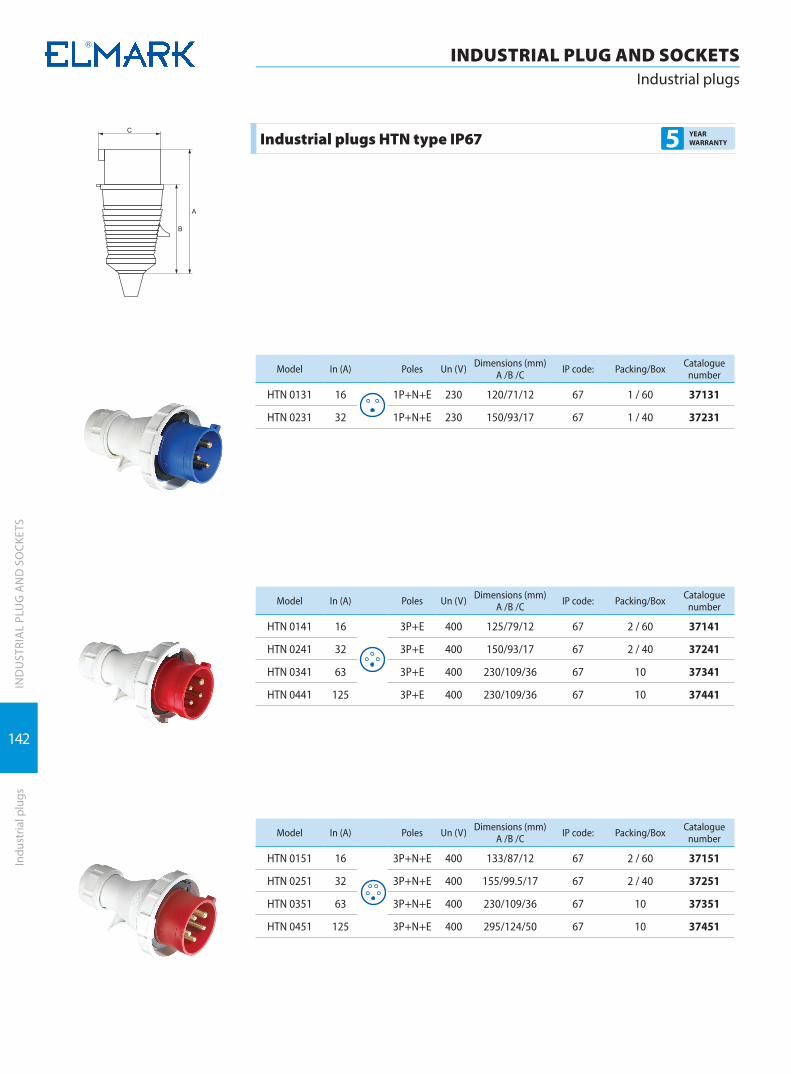
142
INDUSTRIAL PLUG AND SOCKETSIndustrial plugs
IND
UST
RIA
L PL
UG
AN
D S
OCK
ETS
Indu
stria
l plu
gs
Industrial plugs HTN type IP67 5 YEAR WARRANTY
Model In (A) Poles Un (V) Dimensions (mm)A /B /C IP code: Packing/Box Catalogue
number
HTN 0131 16 1P+N+E 230 120/71/12 67 1 / 60 37131
HTN 0231 32 1P+N+E 230 150/93/17 67 1 / 40 37231
Model In (A) Poles Un (V) Dimensions (mm)A /B /C IP code: Packing/Box Catalogue
number
HTN 0141 16 3P+E 400 125/79/12 67 2 / 60 37141
HTN 0241 32 3P+E 400 150/93/17 67 2 / 40 37241
HTN 0341 63 3P+E 400 230/109/36 67 10 37341
HTN 0441 125 3P+E 400 230/109/36 67 10 37441
Model In (A) Poles Un (V) Dimensions (mm)A /B /C IP code: Packing/Box Catalogue
number
HTN 0151 16 3P+N+E 400 133/87/12 67 2 / 60 37151
HTN 0251 32 3P+N+E 400 155/99.5/17 67 2 / 40 37251
HTN 0351 63 3P+N+E 400 230/109/36 67 10 37351
HTN 0451 125 3P+N+E 400 295/124/50 67 10 37451

143
IND
UST
RIA
L PL
UG
AN
D S
OCK
ETS
Indu
stria
l soc
kets
INDUSTRIAL PLUG AND SOCKETSIndustrial sockets
Movable Industrial socket HNT type ip67 5 YEAR WARRANTY
Model In (A) Poles Un (V) Dimensions (mm)A/C IP code: Packing/Box Catalogue
number
HTN 2131 16 1P+N+E 230 131/90 67 2 / 60 37831
HTN 2231 32 1P+N+E 230 149/90 67 2 / 40 37931
Model In (A) Poles Un (V) Dimensions (mm)A/C IP code: Packing/Box Catalogue
number
HTN 2141 16 3P+E 400 131/76 67 2 / 60 37841
HTN 2241 32 3P+E 400 149/90 67 2 / 40 37941
HTN 2341 63 3P+E 400 271/115 67 10 37942
HTN 2441 125 3P+E 400 295/137 67 6 37943
Model In (A) Poles Un (V) Dimensions (mm)A/C IP code: Packing/Box Catalogue
number
HTN 2151 16 3P+N+E 400 139/90 67 2 / 60 37851
HTN 2251 32 3P+N+E 400 154/100 67 2 / 40 37951
HTN 2351 63 3P+N+E 400 240/112 67 10 37952
HTN 2451 125 3P+N+E 400 300/126 67 6 37953
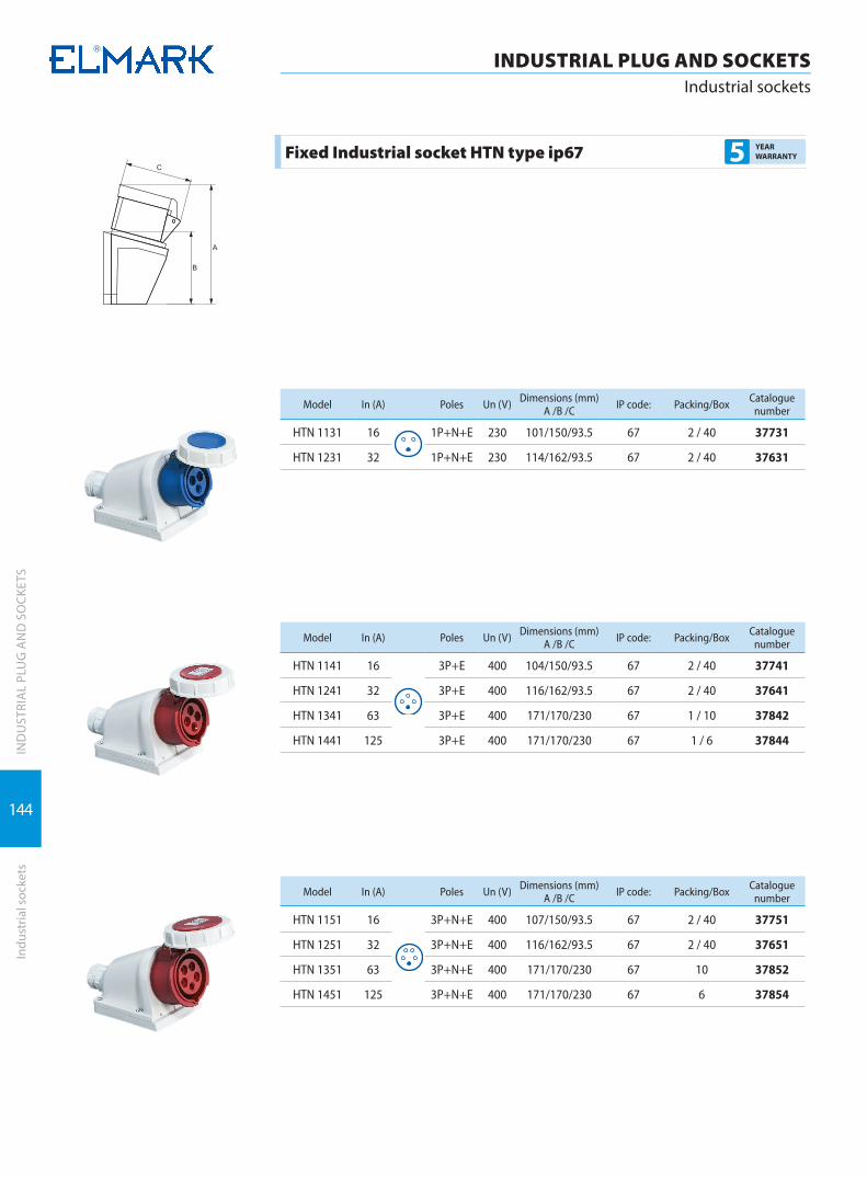
144
IND
UST
RIA
L PL
UG
AN
D S
OCK
ETS
INDUSTRIAL PLUG AND SOCKETSIndustrial sockets
Indu
stria
l soc
kets
Fixed Industrial socket HTN type ip67 5 YEAR WARRANTY
Model In (A) Poles Un (V) Dimensions (mm)A /B /C IP code: Packing/Box Catalogue
number
HTN 1131 16 1P+N+E 230 101/150/93.5 67 2 / 40 37731
HTN 1231 32 1P+N+E 230 114/162/93.5 67 2 / 40 37631
Model In (A) Poles Un (V) Dimensions (mm)A /B /C IP code: Packing/Box Catalogue
number
HTN 1141 16 3P+E 400 104/150/93.5 67 2 / 40 37741
HTN 1241 32 3P+E 400 116/162/93.5 67 2 / 40 37641
HTN 1341 63 3P+E 400 171/170/230 67 1 / 10 37842
HTN 1441 125 3P+E 400 171/170/230 67 1 / 6 37844
Model In (A) Poles Un (V) Dimensions (mm)A /B /C IP code: Packing/Box Catalogue
number
HTN 1151 16 3P+N+E 400 107/150/93.5 67 2 / 40 37751
HTN 1251 32 3P+N+E 400 116/162/93.5 67 2 / 40 37651
HTN 1351 63 3P+N+E 400 171/170/230 67 10 37852
HTN 1451 125 3P+N+E 400 171/170/230 67 6 37854
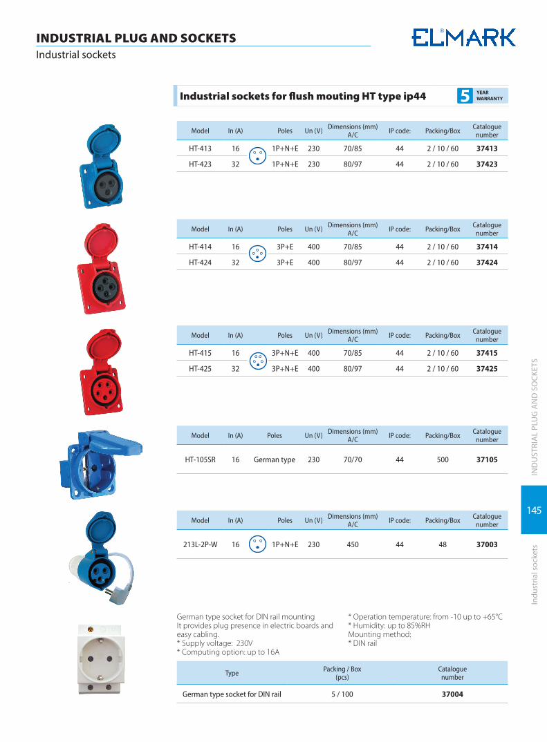
145
IND
UST
RIA
L PL
UG
AN
D S
OCK
ETS
Indu
stria
l soc
kets
INDUSTRIAL PLUG AND SOCKETSIndustrial sockets
Industrial sockets for flush mouting HT type ip44 5 YEAR WARRANTY
Model In (A) Poles Un (V) Dimensions (mm)A/C IP code: Packing/Box Catalogue
number
HT-413 16 1P+N+E 230 70/85 44 2 / 10 / 60 37413
HT-423 32 1P+N+E 230 80/97 44 2 / 10 / 60 37423
Model In (A) Poles Un (V) Dimensions (mm)A/C IP code: Packing/Box Catalogue
number
HT-414 16 3P+E 400 70/85 44 2 / 10 / 60 37414
HT-424 32 3P+E 400 80/97 44 2 / 10 / 60 37424
Model In (A) Poles Un (V) Dimensions (mm)A/C IP code: Packing/Box Catalogue
number
HT-415 16 3P+N+E 400 70/85 44 2 / 10 / 60 37415
HT-425 32 3P+N+E 400 80/97 44 2 / 10 / 60 37425
Model In (A) Poles Un (V) Dimensions (mm)A/C IP code: Packing/Box Catalogue
number
HT-105SR 16 German type 230 70/70 44 500 37105
Model In (A) Poles Un (V) Dimensions (mm)A/C IP code: Packing/Box Catalogue
number
213L-2P-W 16 1P+N+E 230 450 44 48 37003
German type socket for DIN rail mounting It provides plug presence in electric boards and easy cabling. * Supply voltage: 230V* Computing option: up to 16А
* Operation temperature: from -10 up to +65°С* Humidity: up to 85%RHMounting method:* DIN rail
Type Packing / Box(pcs)
Catalogue number
German type socket for DIN rail 5 / 100 37004
DISTRIBUTION BOXES
DISTRIBUTIONBOXES
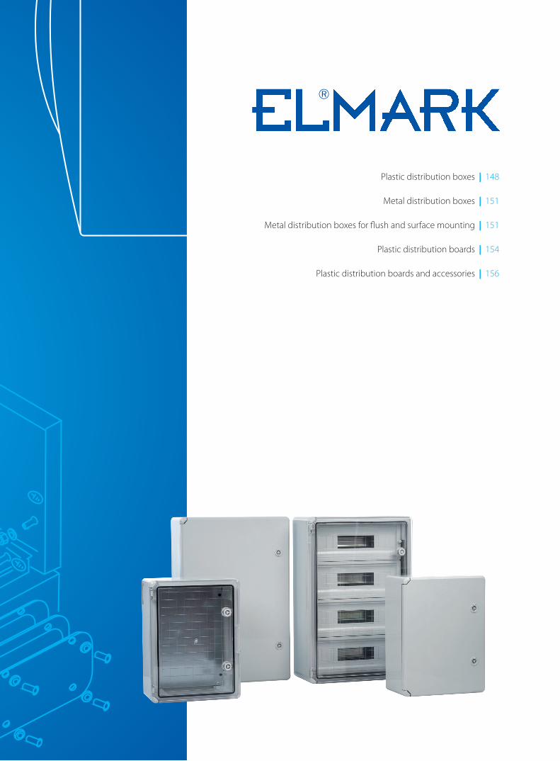
Plastic distribution boxes | 148
Metal distribution boxes | 151
Metal distribution boxes for flush and surface mounting | 151
Plastic distribution boards | 154
Plastic distribution boards and accessories | 156

148
DISTRIBUTION BOXESPlastic distribution boards
DIS
TRIB
UTI
ON
BO
XES
Plas
tic d
istr
ibut
ion
boar
ds
Plastic distribution boxes for surface and flush mounting IP40 3 YEAR
WARRANTY
The distribution boxes are designed for mounting in newly built buildings or buildings in reconstruction. They are a module box with mounted protective devices of the given flats electrical current circuit circles. They are supplied with transparent door for each row opening upwards to 90°. They are made of white self-extin-guishing plastic, resistant to heat and high temperature with IP code: IP 40. The mounted device in the box is protected from direct contact to the current leading parts. They are offered with DIN-rail for device mounting and terminal strips for the neutral and earthing conductor joining. Mounted directly on the walls with screws.
Technical data: � Maximum insulation voltage: 690V; 50Hz � fire resistance rate: UL 94 � IP code: IP 40 � Class of current limiting: 2
Documents corresponding to the product: Standard EN 62 208; EN 60439-1; EN 60 439-3
Boxes for surface mounting
Number of rowsModule capacity
(number of devices)
Dimensions (mm)Packing / Box Catalogue number
L H W
1 4 110 205 75 1 / 20 60040
1 6 150 205 75 1 / 20 60060
1 8 190 205 75 1 / 20 60080
Boxes for flush mounting
Number of rowsModule capacity
(number of devices)
Dimensions (mm)Packing / Box Catalogue number
L H W
1 4 110 205 75 1 / 20 60041
1 6 150 205 75 1 / 20 60061
1 8 190 205 75 1 / 20 60081

149
DISTRIBUTION BOXESPlastic distribution boards
DIS
TRIB
UTI
ON
BO
XES
Plas
tic d
istr
ibut
ion
boar
ds
Plastic distribution boxes for surface and flush mounting IP40 3 YEAR
WARRANTY
The distribution boxes are designed for mounting in newly built buildings or buildings in reconstruction. They are a module box with mounted protective devices of the given flats electrical current circuit circles. They are supplied with transparent door for each row opening upwards to 90°. They are made of white self-extin-guishing plastic, resistant to heat and high temperature with IP code: IP 40. The mounted device in the box is protected from direct contact to the current leading parts. They are offered with DIN-rail for device mounting and terminal strips for the neutral and earthing conductor joining. Mounted directly on the walls with screws.
Technical data: � Door colour: Transparent blue � Mounting type: Surface;Flush � Modules (№): 12; 18; 24; 28; 36 � IP code: IP30 � Row: Single row for 12 and 18 modules � Double rows for 24; 28 and 36 modules � Material: ABS for body and PC for door � Fire resistance: 650°C/30s � Ambient temperature(°C): -5 +65°C, max. 95% humidity � Colour: White RAL 9003 � Storage temperature(°C): -40 +75°C
Documents corresponding to the product: Standard EN 62 208; EN 60439-1; EN 60 439-3
Boxes for surface mounting
Number of rows Module capacity(number of devices)
Dimensions (mm)Packing / Box Catalogue
numberL H W
1 12 300 204 102 1/10 60122
1 18 410 204 102 1/10 60182
2 24 300 294 109 1/5 60242
2 28 310 354 109 1/5 60282
2 36 410 294 109 1/5 60362
Boxes for flush mounting
Number of rows Module capacity(number of devices)
Dimensions (mm)Packing / Box Catalogue
numberL H W
1 12 317 220 102 1/10 60123
1 18 426 220 102 1/10 60183
2 24 317 310 109 1/5 60243
2 28 294 338 109 1/5 60283
2 36 426 310 109 1/5 60363

150
DISTRIBUTION BOXESPlastic distribution boards
DIS
TRIB
UTI
ON
BO
XES
Moisture-proof distribution boxes for surface mounting - IP 55; IP65 3 YEAR
WARRANTY
The distribution boxes are designed for mounting in newly built buildings or buildings in reconstruction. They are a module box with mounted protective devices of the given flats electrical installation current circles. They are supplied with transparent door for each row opening upwards to 90°. They are made of white non-self-ex-tinguishing plastic, resistant to heat and high temperature. The special design of the lids and gaskets provides IP code: IP55; IP65. The mounted device in the box is protected from indirect contact to the current leading parts. They are offered with DIN-rail for device mounting and terminal strips for the neutral and earthing conductor joining. For direct wall moutining with screws.
Technical data: � Maximum insulation voltage: 690V; 50Hz � Flame retardance: UL94 V-O � IP code: IP55; IP65 � Door colour: Transparent � Mounting type: Surface
Documents corresponding to the product: Standard EN 62 208; EN 60439-1; EN 60 439-3
Moisture-proof distribution boxes for surface mounting - IP 55
Type Number of rows
Module capacity(number of
devices)IP
Dimensions (mm)Packing /
BoxCatalogue
numberL H W
WP4 1 4 55 127 214 93 1 / 20 60100
WP6 1 6 55 162 214 93 1 / 20 60101
WP8 1 8 55 216 214 93 1 / 20 60102
WP12 1 12 55 270 214 93 1 / 12 60103
WP18 1 18 55 378 233 93 1 / 8 60104
WP24 2 24 55 340 288 93 1 / 8 60105
Moisture-proof distribution boxes for surface mounting - IP 65
Type Number of rows
Module capacity(number of
devices)IP
Dimensions (mm)Packing /
BoxCatalogue
numberL H W
WPDB 04 1 4 65 140 210 100 1/30 60004
WPDB 08 1 8 65 215 210 100 1/20 60008
WPDB 12 1 12 65 300 260 140 1/10 60012
WPDB 18 1 18 65 410 285 140 1/5 60018
WPDB 24 2 24 65 415 300 140 1/5 60024

151
DIS
TRIB
UTI
ON
BO
XES
Met
al d
istr
ibut
ion
boar
ds
DISTRIBUTION BOXESMetal distribution boards
Metal distribution boxes for flush and surface mounting 3 YEAR WARRANTY
Technical data: � Maximum insulation voltage: 690V; 50Hz � Flame retardance: V-0 � IP code: IP40 � Colour: Gray � Mounting type: Surface and flush
Type Number of poles
Module capacity (number of
devices)
Dimensions (mm)Packing /
BoxCatalogue
numberH L W
MDB 1/4 1 4 251 190 90 1/10 600104
MDB 1/8 1 8 251 262 90 1/10 600108
MDB 1/12 1 12 251 334 90 1/10 600112
MDB 1/16 1 16 251 406 90 1/10 600116
Type Number of poles
Module capacity (number of
devices)
Dimensions (mm)Packing /
BoxCatalogue
numberH L W
MDB 3/4 3 4 454 406 114 1/2 600304
MDB 3/6 3 6 508 406 114 1/2 600306
MDB 3/8 3 8 562 406 114 1/2 600308
MDB 3/10 3 10 616 406 114 1/2 600310
MDB 3/12 3 12 670 406 114 1/2 600312
Stainless steel metal boards 3 YEAR WARRANTY
Supplied with a special lock, metal plate for fixing of electrical devices, lid for the input-output conductors, grounded dowel pin, gaskets, etc. Option to change the opening direction. Made of single stainless steel sheet. The mouting plate is treated with anti-corrosion and decorative powder coating. They are used in case of special requirements regarding the exposure of corrosion.
Technical data: � Rated voltage: up to 1000V � Maximum current: up to 800A � Material: stainless steel � IP code: IP 65
Mounting: � vertically on flat surface
Documents corresponding to the product: Standard EN 62 208; EN 60439-1; EN 60 439-3
TypeThickness of metal
sheet(mm)
Metal box dimensions (mm)Packing / Box
Catalogue number
L (height) W (width) H (depth)
SXF 25/25/15 1.0 250 250 150 1 54025
SXF 30/25/15 1.0 300 250 150 1 54030
SXF 40/30/20 1.0 400 300 200 1 54040
SXF 50/40/20 1.2 500 400 200 1 54050
SXF 60/40/20 1.2 600 400 200 1 54060
SXF 70/50/20 1.2 700 500 200 1 54070
SXF 80/60/25 1.5 800 600 250 1 54080
SXF 100/80/30 1.5 1000 800 300 1 54100
SXF 120/80/30 1.5 1200 800 300 1 54120
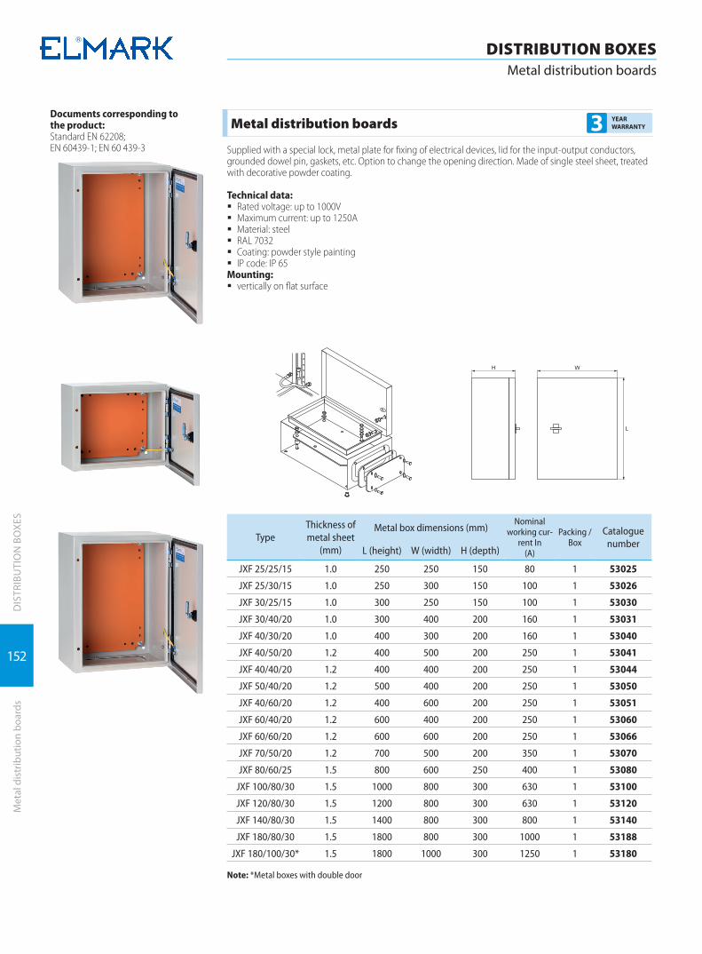
152
DIS
TRIB
UTI
ON
BO
XES
Met
al d
istr
ibut
ion
boar
ds
DISTRIBUTION BOXESMetal distribution boards
Metal distribution boards 3 YEAR WARRANTY
Supplied with a special lock, metal plate for fixing of electrical devices, lid for the input-output conductors, grounded dowel pin, gaskets, etc. Option to change the opening direction. Made of single steel sheet, treated with decorative powder coating.
Technical data: � Rated voltage: up to 1000V � Maximum current: up to 1250A � Material: steel � RAL 7032 � Coating: powder style painting � IP code: IP 65
Mounting: � vertically on flat surface
Documents corresponding to the product: Standard EN 62208; EN 60439-1; EN 60 439-3
TypeThickness of metal sheet
(mm)
Metal box dimensions (mm)Nominal
working cur-rent In
(A)
Packing / Box
Catalogue number
L (height) W (width) H (depth)
JXF 25/25/15 1.0 250 250 150 80 1 53025
JXF 25/30/15 1.0 250 300 150 100 1 53026
JXF 30/25/15 1.0 300 250 150 100 1 53030
JXF 30/40/20 1.0 300 400 200 160 1 53031
JXF 40/30/20 1.0 400 300 200 160 1 53040
JXF 40/50/20 1.2 400 500 200 250 1 53041
JXF 40/40/20 1.2 400 400 200 250 1 53044
JXF 50/40/20 1.2 500 400 200 250 1 53050
JXF 40/60/20 1.2 400 600 200 250 1 53051
JXF 60/40/20 1.2 600 400 200 250 1 53060
JXF 60/60/20 1.2 600 600 200 250 1 53066
JXF 70/50/20 1.2 700 500 200 350 1 53070
JXF 80/60/25 1.5 800 600 250 400 1 53080
JXF 100/80/30 1.5 1000 800 300 630 1 53100
JXF 120/80/30 1.5 1200 800 300 630 1 53120
JXF 140/80/30 1.5 1400 800 300 800 1 53140
JXF 180/80/30 1.5 1800 800 300 1000 1 53188
JXF 180/100/30* 1.5 1800 1000 300 1250 1 53180
Note: *Metal boxes with double door
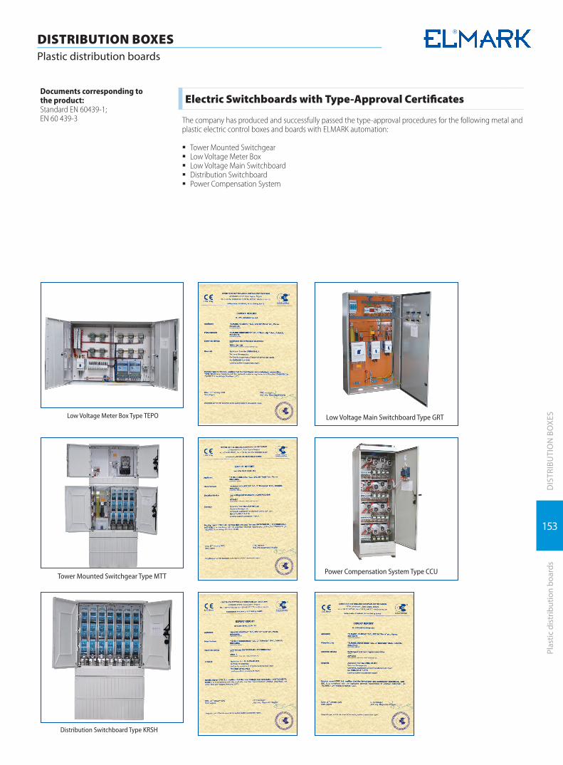
153
DISTRIBUTION BOXESPlastic distribution boards
DIS
TRIB
UTI
ON
BO
XES
Plas
tic d
istr
ibut
ion
boar
ds
Electric Switchboards with Type-Approval Certificates
The company has produced and successfully passed the type-approval procedures for the following metal and plastic electric control boxes and boards with ELMARK automation:
� Tower Mounted Switchgear � Low Voltage Meter Box � Low Voltage Main Switchboard � Distribution Switchboard � Power Compensation System
Documents corresponding to the product: Standard EN 60439-1;EN 60 439-3
Low Voltage Meter Box Type TEPO Low Voltage Main Switchboard Type GRT
Tower Mounted Switchgear Type MTT
Distribution Switchboard Type KRSH
Power Compensation System Type CCU
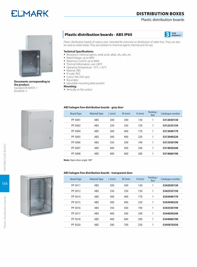
154
DISTRIBUTION BOXESPlastic distribution boards
DIS
TRIB
UTI
ON
BO
XES
Plas
tic d
istr
ibut
ion
boar
ds
Plastic distribution boards - ABS IP65 3 YEAR WARRANTY
Plastic distribution boards of various sizes. Intended for extension or distribution of cable lines. They can also be used as meter boxes. They are resistant to chemical agents, thermal and UV rays.
Technical Specifications: � Resistance: chemical agents, weak acids, alkali, oils, salts, etc. � Rated Voltage: up to 690V � Maximum Current: up to 800A � Thermal Deformation: over 240°C � Operating Temperature: -35°C + 65°C � Material: ABS � IP code: IP65 � Colour: RAL7035 grey � Recyclable � adjustable mounting plate position
Mounting: � Vertically on flat surface
Documents corresponding to the product: Standard EN 60439 -1 EN 60439 -5
ABS halogen free distribution boards - gray door
Board Type Material Type L (mm) W (mm) H (mm) Packing / Box Catalogue number
PP 3001 ABS 200 300 130 1 5312030130
PP 3002 ABS 250 350 150 1 5312535150
PP 3004 ABS 300 400 170 1 5313040170
PP 3005 ABS 300 400 220 1 5313040220
PP 3006 ABS 350 500 190 1 5313550190
PP 3007 ABS 400 500 240 1 5314050240
PP 3008 ABS 400 600 200 1 5314060190
Note: Open door angle 180°
ABS halogen free distribution boards - transparent door
Board Type Material Type L (mm) W (mm) H (mm) Packing / Box Catalogue number
PP 3011 ABS 200 300 130 1 5342030130
PP 3012 ABS 250 350 150 1 5342535150
PP 3014 ABS 300 400 170 1 5343040170
PP 3015 ABS 300 400 220 1 5343040220
PP 3016 ABS 350 500 190 1 5343550190
PP 3017 ABS 400 500 240 1 5344050240
PP 3018 ABS 400 600 200 1 5344060190
PP 3020 ABS 500 700 250 1 5345070250

155
DISTRIBUTION BOXESPlastic distribution boards
DIS
TRIB
UTI
ON
BO
XES
Plas
tic d
istr
ibut
ion
boar
ds
ABS halogen free distribution module boards - transparent door
Board Type Material Type L (mm) W (mm) H (mm) Packing / Box Catalogue number
PP 3112-18modules ABS 250 330 130 1 5322535150
PP 3114-24modules ABS 300 350 150 1 5323040170
PP 3116-45modules ABS 350 500 190 1 5323550190
PP 3118-60modules ABS 400 600 200 1 5324060190
Note: Transperent door
Surface mounting polyester boards EC - IP65 3 YEAR WARRANTY
Technical Specifications: � Colour: grey RAL 7035. � IP65 protection degree. � Material: made of halogen free reinforced fiberglass polyester, self-extinguishing V0 degree according to
UL94. � Double insulation, shock resistance: IK10, 20j, according to EN 62262. � Application temperature: minimum –25°, maximum +65°. � Resistance to abnormal heat (GWT)- board with blank door up to 960°C - board with transparent window
up to 650°C. � Application voltage 1000V, suitable for photovoltaic plants. � Right or left reversible door with stainless steel pins – it can be opened more than 180°. � Plain and smooth headboards for easy opening and conduit inlet. � Removable frame ready to install slotted trunkings in the back. � Back plates made up of metal or insulating material can be fixed directly to the board back, also if the frame
is used, or can be adjusted to different heights through the kit EC625REG. � Possibility to mount 48-75mm high switches or 102mm high switches starting from the board with dimen-
sions 435x505x215. � One-Screw-System: only one type of screws is used for the different accessories in order to permit a simple
and easy assembly. � Left or right reversible counter door with stainless steel pins, ergonomic handle, triangle lock, adjustable at
two different heights with reference grid for the fixing of the devices. � Fixing of the single/double blank or windowed panels through a ¼ turn screws.
Halogen free polyester boards EC- blank door
Type Material L (mm) W (mm) H (mm) Packing /Box Catalogue number
PBBD 5001 Polyester 270 305 170 1 5332730170
PBBD 5002 Polyester 325 430 185 1 5333243185
PBBD 5003 Polyester 435 505 215 1 5334350215
PBBD 5004 Polyester 435 655 215 1 5334365215
PBBD 5005 Polyester 545 655 265 1 5335465265
PBBD 5006 Polyester 620 810 320 1 5336281320
*Detailed installation instructions and information about the functions and applications of all additional acces-sories for polyester boxes, you can find on: www.elmarkholding.eu

156
DISTRIBUTION BOXESPlastic distribution boards and accessories
DIS
TRIB
UTI
ON
BO
XES
Plas
tic d
istr
ibut
ion
boar
ds a
nd a
cces
sorie
s
Halogen free polyester boards EC - transparent door
Type Material L (mm) W (mm) H (mm) Packing /Box Catalogue number
PBTD 5001 Polyester 270 305 170 1 5362730170
PBTD 5002 Polyester 325 430 185 1 5363243185
PBTD 5003 Polyester 435 505 215 1 5364350215
PBTD 5004 Polyester 435 655 215 1 5364365215
PBTD 5005 Polyester 545 655 265 1 5365465265
PBTD 5006 Polyester 620 810 320 1 5366281320
Polyester hinger counterdoor EC
Type Material Used for type boards Packing /Box Catalogue number
CD 5002 Polyester PBTD/PBBD 5002 1 53502CD
CD 5003 Polyester PBTD/PBBD 5003 1 53503CD
CD 5004 Polyester PBTD/PBBD 5004 1 53504CD
CD 5005 Polyester PBTD/PBBD 5005 1 53505CD
CD 5006 Polyester PBTD/PBBD 5006 1 53505CD
Metal back plate EC
Type Dimensions Used for type boards Packing /Box Catalogue number
MP 5001 207x239 PBTD/PBBD 5001 1 53501MP
MP 5002 264x364 PBTD/PBBD 5002 1 53502MP
MP 5003 372x439 PBTD/PBBD 5003 1 53503MP
MP 5004 372x589 PBTD/PBBD 5004 1 53504MP
MP 5005 482x589 PBTD/PBBD 5005 1 53505MP
MP 5006 556x739 PBTD/PBBD 5006 1 53506MP
Insulanting plastic back plate EC
Type Dimensions Used for type boards Packing /Box Catalogue number
IBP 5001 207x239 PBTD/PBBD 5001 1 53501IBP
IBP5002 264x364 PBTD/PBBD 5002 1 53502IBP
IBP5003 372x439 PBTD/PBBD 5003 1 53503IBP
IBP 5004 372x589 PBTD/PBBD 5004 1 53504IBP
IBP 5005 482x589 PBTD/PBBD 5005 1 53505IBP
IBP 5006 556x739 PBTD/PBBD 5006 1 53506IBP
*Detailed installation instructions and information about the functions and applications of all additional acces-sories for polyester boxes, you can find on: www.elmarkholding.eu

157
DISTRIBUTION BOXESAccessories for plastic distribution boards
DIS
TRIB
UTI
ON
BO
XES
Acce
ssor
ies
for p
last
ic d
istr
ibut
ion
boar
ds
Pair of uprights for rail DIN and panels EC
Type Used for type boards Packing /Box Catalogue number
DP 5002 PBTD/PBBD 5002 1 pair 53502DP
DP 5003 PBTD/PBBD 5003 1 pair 53503DP
DP 5004 PBTD/PBBD 5004/5005 1 pair 53504DP
DP 5006 PBTD/PBBD 5006 1 pair 53506DP
DIN rail with support EC
Type Module capacity Used for type boards Packing /Box Catalogue number
DS 5002 12 PBTD/PBBD 5002 1 53502DS
DS 5003 18 PBTD/PBBD 5003/5004 1 53503DS
DS 5004 24 PBTD/PBBD 5005 1 53504DS
DS 5005 28 PBTD/PBBD 5006 1 53505DS
Cover module with window EC
Type Module capacity Used for type boards Packing /Box Catalogue number
CMW 5002 12 PBTD/PBBD 5002 1 53502CMW
CMW 5003 18 PBTD/PBBD 5003/5004 1 53503CMW
CMW 5004 24 PBTD/PBBD 5005 1 53504CMW
CMW 5005 28 PBTD/PBBD 5006 1 53505CMW
Blank cover module EC
TypeHeigth of
single/double cover (mm)
Used for type boards Packing /Box
Catalogue number
single cover
Catalogue number
double cover
Blank cover module
125/250 PBTD/PBBD 5002 1 53502S 53502D
150/300 PBTD/PBBD 5003/5004 1 53503S 53503D
150/300 PBTD/PBBD 5005 1 53505S 53505D
150/300 PBTD/PBBD 5006 1 53506S 53506D
Deep adjusment back plate kit EC
Type Used for type boards Need kits Packing /Box Catalogue number
Deep adjusment back plate kit
PBTD/PBBD 5002/5003 2kit 1 kit (2 pcs) 53507
PBTD/PBBD 5004/5005 3kit 1 kit (2 pcs) 57508
PBTD/PBBD 5006 4kit 1 kit (2 pcs) 53509
Spare brass and brackets for fixing- galvanized EC
Type Used for type boards Packing /Box Catalogue number
Galvanized brackets All type 1 kit (4 pcs) 53510
Spare brass insert kit All type 1 kit (10 pcs) 53512
Safety lock EC
Type Used for type boards Packing /Box Catalogue number
Safety lock All type 1 53511
Note: Lock supplied with two unified keys. The keys are inified and open all the locks
CABLE TERMINALS
CABLETERMINALS

Connection tubes | 160
Isolated cable terminals | 163

160
CA
BLE
TERM
INA
LS
CABLE TERMINALSCable terminals without isolation
Cabl
e te
rmin
als
with
out i
sola
tion
Connection tubes - GTY type 3 YEAR WARRANTY
Copper pipes with galvanic tin coating, used for joining of copper rigid or multicore conductors with different sections. The assembling is made by mechanical pressing with crimping tool.
Technical data: � Material: copper alloy � Coating: tin � Application: general
Standard: EN 61 238-1
Type LengthL (mm)
Outer diameterD (mm)
Inner diameter d (mm)
Cable (mm2)
Packing / Box (pcs) Catalogue number
GTY-4 20 5 3 4 1000 / 16000 59213
GTY-6 25 5.3 3.7 6 500 / 1500 / 12000 59201
GTY-10 30 6.3 4.5 10 500 / 1500 / 12000 59202
GTY-16 35 7.5 5.7 16 100 / 200 / 4800 59203
GTY-25 40 9 7.2 25 100 / 500 / 2000 59204
GTY-35 45 10.8 8.5 35 100 / 200 / 1600 59205
GTY-50 50 12.5 9.8 50 20 / 200 / 1600 59206
GTY-70 55 14.5 11.5 70 10 / 100 / 800 59207
GTY-95 60 17 13.7 95 10 / 80 / 640 59208
GTY-120 65 19 15 120 10 / 60 / 480 59209
GTY-150 70 21 16.7 150 10 / 50 / 400 59210
GTY-185 75 23 18.5 185 10 / 40 / 320 59211
GTY-240 80 26 21 240 10 / 30 / 240 59212
Bimetallic connection tube - GTL type 3 YEAR WARRANTY
Pipes made of two metals – copper and aluminum without galvanic coating. They are designed for joining copper and aluminum conductors – rigid or multicore conductors with different section. The connection is accomplished through crimping pliers, through mechanical pressing of the butt terminals and the conductor. They are used for protection against electrochemical corrosion got at two metals contact with different chemi-cal properties and conductivity at electrical current feed. They are manufactured under modern technology and have high quality and long exploitation period.
Technical data: � Material: copper aluminum alloy � Coating: none � Application: general for joining of two types of conductors
Standard: EN 61 238-1 Butt terminal type d1 D1 d2 D2 l1 l2 L Packing / Box (pcs) Catalogue
number
GTL - 16 5 9 6 10 30 30 75 20 / 200 / 1200 59214
GTL - 25 6 10 7 12 30 33 82 20 / 400 / 1500 59215
GTL - 35 7 11 8.5 14 30 40 90 20 / 300 / 1000 59216
GTL - 50 8.5 13 9.8 16 32 42 95 20 / 800 59217
GTL - 70 9.5 15 11.5 18 38 50 105 10 / 600 59218
GTL - 95 11.5 17 13.5 21 40 50 110 10 / 500 59219
GTL - 120 13.5 19 15 23 42 55 112 10 / 400 59220
GTL - 150 15 21 17 25 44 55 118 10 / 350 59221
GTL - 185 17 23 18.5 27 46 60 125 10 / 300 59222
GTL - 240 19 26 21 30 54 60 130 10 / 200 59223
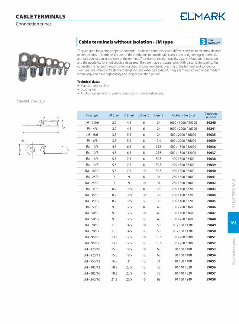
161
CABLE TERMINALSConnection tubes
CA
BLE
TERM
INA
LSCo
nnec
tion
tube
s
Cable terminals without isolation - JM type 3 YEAR WARRANTY
They are used for joining copper conductors - multicore conductors with different section to electrical devices or connections to combine all cores of the conductor, to provide safe connection at tightening in terminals and safe connection at the base of the terminal. Thus the connection stability against vibrations is increased and the possibility for short circuit is decreased. They are made of copper alloy with galvanic tin coating. The connection is realized through crimping pliers, through mechanic pressing of the terminal and conductor. Two types are offered with standard length SC and extended base JM. They are manufactured under modern technology and have high quality and long exploitation period.
Technical data: � Material: copper alloy � Coating: tin � Application: general for joining conductors to electrical devices.
Standard: EN 61 238-1
Shoe type d1 (mm) D (mm) d2 (mm) L (mm) Packing / Box (pcs) Catalogue number
JM - 2.5/6 2.2 4.5 6 24 1000 / 3000 / 24000 59240
JM - 4/6 3.0 4.8 6 24 1000 / 2000 / 16000 59241
JM - 6/6 3.8 5.5 6 24 500 / 2000 / 16000 59035
JM - 6/8 3.8 5.5 8 2 4 500 / 2000 / 16000 59059
JМ - 10/6 4.8 6.8 6 25.5 500 / 1500 / 12000 59036
JM - 10/8 4.8 6.8 8 25.5 500 / 1500 / 12000 59037
JM - 16/6 5.5 7.5 6 30.5 400 / 800 / 6400 59038
JM - 16/8 5.5 7.5 8 30.5 400 / 800 / 6400 59039
JM - 16/10 5.5 7.5 10 30.5 400 / 800 / 6400 59040
JM - 25/8 7 9 8 34 250 / 500 / 4000 59041
JM - 25/10 7 9 10 34 250 / 500 / 4000 59042
JM - 35/8 8.2 10.5 8 38 200 / 400 / 3200 59043
JM - 35/10 8.2 10.5 10 38 200 / 400 / 3200 59044
JM - 35/12 8.2 10.5 12 38 200 / 400 / 3200 59045
JM - 50/8 9.8 12.5 8 45 100 / 200 / 1600 59046
JM - 50/10 9.8 12.5 10 45 100 / 100 / 1600 59047
JM - 50/12 9.8 12.5 12 45 100 / 200 / 1600 59048
JM - 70/10 11.5 14.5 10 50 80 / 100 / 1280 59049
JM - 70/12 11.5 14.5 12 50 80 / 100 / 1280 59050
JM - 95/10 13.8 17.5 10 55.5 50 / 200 / 800 59051
JM - 95/12 13.8 17.5 12 55.5 50 / 200 / 800 59052
JM - 120/10 15.5 19.5 10 63 30 / 60 / 480 59053
JM - 120/12 15.5 19.5 12 63 30 / 60 / 480 59054
JM - 150/12 16.5 21 12 71 10 / 50 / 400 59055
JM - 185/12 18.8 23.5 12 78 10 / 40 / 320 59056
JM - 185/16 18.8 23.5 16 78 10 / 40 / 320 59057
JM - 240/16 21.3 26.5 16 92 10 / 30 / 240 59058

162
CA
BLE
TERM
INA
LS
CABLE TERMINALSCable terminals without isolation
Cabl
e te
rmin
als
with
out i
sola
tion
Bimetalic non-isolated cable terminals for crimping DTL 3 YEAR
WARRANTY
They are used for joining aluminum conductors - multicore conductors with different section to electrical devices or connections to combine all cores of the conductor, to provide safe connection at tightening in terminals and safe connection at the base of the terminal. Thus the connection stability against vibrations is increased and the possibility for short circuit is decreased. They are made of copper and aluminum alloys as in the aluminum billet is made under special technology the copper terminal formed like an ear. The connec-tion is realized through crimping pliers, through mechanic pressing of the terminal and conductor. They are manufactured under modern technology and have high quality and long exploitation period.
Technical data: � Material: copper aluminum � Application: general for joining conductors to electrical devices.
Standard: EN 61 238-1
Shoe type d1(mm)
D(mm)
d2(mm)
L(mm)
l(mm)
B(mm) Packing / Box (pcs) Catalogue
number
DTL - 1 - 16 6 11 8 70 30 16 20 / 200 / 1440 59224
DTL - 1 - 25 7 12 8 75 34 18 20 / 180 / 1080 59225
DTL - 1 - 35 8.5 14 10 85 38 20.5 20 / 100 / 600 59226
DTL - 1 - 50 9.8 16 10 90 40 23 20 / 70 / 420 59227
DTL - 1 - 70 11.5 18 12 102 48 26 10 / 60 / 360 59228
DTL - 1 - 95 13.5 21 12 112 50 28 10 / 40 / 180 59229
DTL - 1 - 120 15 23 14 120 53 30 10 / 30 / 120 59230
DTL - 1 - 150 16.5 25 14 126 56 34 5 / 25 / 120 59231
DTL - 1 - 185 18.5 27 16 133 58 37 5 / 20 / 120 59232
DTL - 1 - 240 21 30 16 140 60 40 4 / 12 / 72 59233
Copper cable wire fork terminal connector 3 YEAR WARRANTY
Type Length (mm) Colour Conductor
(mm2) Packing (pcs.) Packing / Box (pcs.) Catalogue number
SVS1.25-4 21.2 Red 0.5-1.5 100 10 / 240 59080
SVS1.25-5 21.2 Red 0.5-1.5 100 15 / 180 59081
SVS1.25-6 21.2 Red 0.5-1.5 100 15 / 180 59082
SVS 2-4 21.0 Blue 1.5-2.5 100 15 / 180 59083
SVS 2-5 22.5 Blue 1.5-2.5 100 15 / 180 59084
SVS 2-6 27,6 Blue 1.5-2.5 100 10 / 120 59085
SVS 5,5-4 24.5 Yellow 4-6 100 5 / 60 59086
SVS 5,5-5 27,9 Yellow 4-6 100 5 / 60 59087
SVS 5,5-6 27,9 Yellow 4-6 100 5 / 60 59088
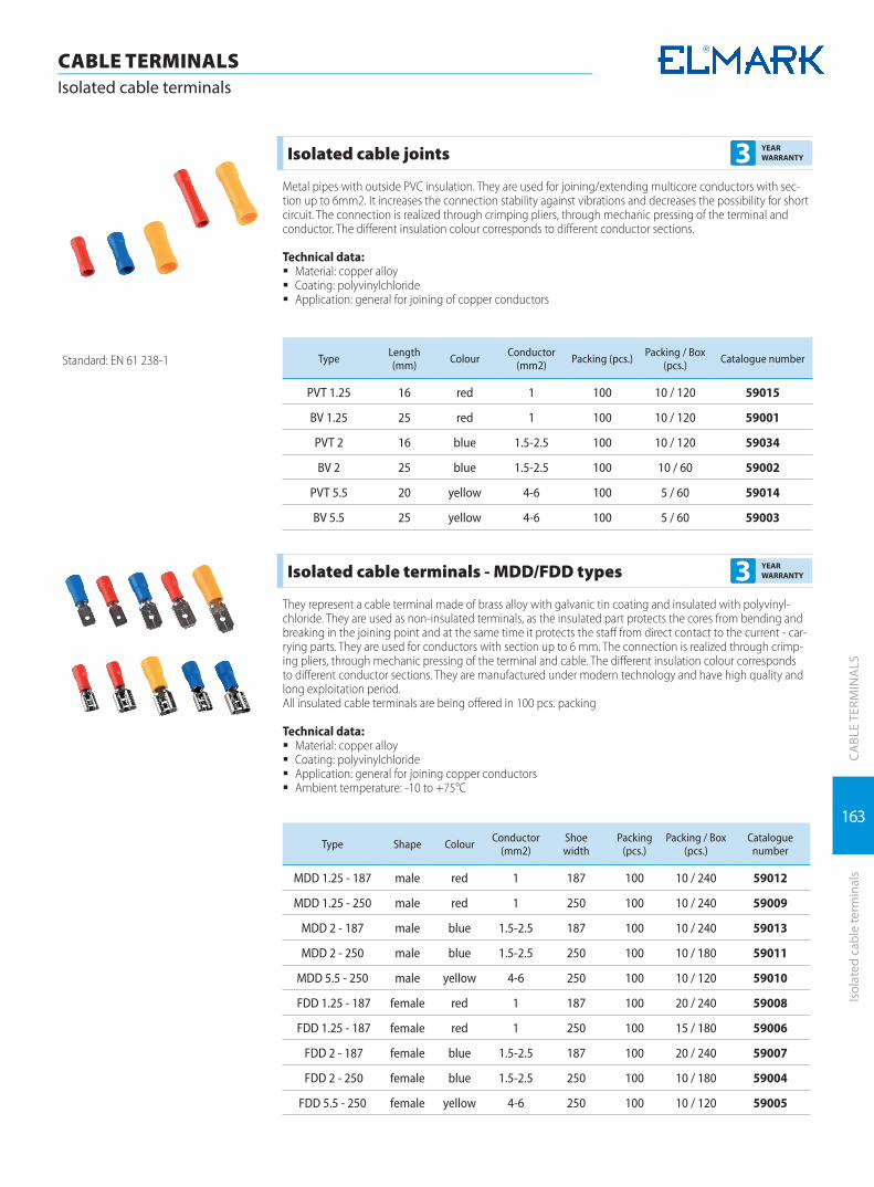
163
CA
BLE
TERM
INA
LSIs
olat
ed c
able
term
inal
s
CABLE TERMINALSIsolated cable terminals
Isolated cable joints 3 YEAR WARRANTY
Metal pipes with outside PVC insulation. They are used for joining/extending multicore conductors with sec-tion up to 6mm2. It increases the connection stability against vibrations and decreases the possibility for short circuit. The connection is realized through crimping pliers, through mechanic pressing of the terminal and conductor. The different insulation colour corresponds to different conductor sections.
Technical data: � Material: copper alloy � Coating: polyvinylchloride � Application: general for joining of copper conductors
Standard: EN 61 238-1 Type Length (mm) Colour Conductor
(mm2) Packing (pcs.) Packing / Box (pcs.) Catalogue number
PVT 1.25 16 red 1 100 10 / 120 59015
BV 1.25 25 red 1 100 10 / 120 59001
PVT 2 16 blue 1.5-2.5 100 10 / 120 59034
BV 2 25 blue 1.5-2.5 100 10 / 60 59002
PVT 5.5 20 yellow 4-6 100 5 / 60 59014
BV 5.5 25 yellow 4-6 100 5 / 60 59003
Isolated cable terminals - MDD/FDD types 3 YEAR WARRANTY
They represent a cable terminal made of brass alloy with galvanic tin coating and insulated with polyvinyl-chloride. They are used as non-insulated terminals, as the insulated part protects the cores from bending and breaking in the joining point and at the same time it protects the staff from direct contact to the current - car-rying parts. They are used for conductors with section up to 6 mm. The connection is realized through crimp-ing pliers, through mechanic pressing of the terminal and cable. The different insulation colour corresponds to different conductor sections. They are manufactured under modern technology and have high quality and long exploitation period.All insulated cable terminals are being offered in 100 pcs. packing
Technical data: � Material: copper alloy � Coating: polyvinylchloride � Application: general for joining copper conductors � Ambient temperature: -10 to +75°C
Type Shape Colour Conductor (mm2)
Shoewidth
Packing (pcs.)
Packing / Box (pcs.)
Catalogue number
MDD 1.25 - 187 male red 1 187 100 10 / 240 59012
MDD 1.25 - 250 male red 1 250 100 10 / 240 59009
MDD 2 - 187 male blue 1.5-2.5 187 100 10 / 240 59013
MDD 2 - 250 male blue 1.5-2.5 250 100 10 / 180 59011
MDD 5.5 - 250 male yellow 4-6 250 100 10 / 120 59010
FDD 1.25 - 187 female red 1 187 100 20 / 240 59008
FDD 1.25 - 187 female red 1 250 100 15 / 180 59006
FDD 2 - 187 female blue 1.5-2.5 187 100 20 / 240 59007
FDD 2 - 250 female blue 1.5-2.5 250 100 10 / 180 59004
FDD 5.5 - 250 female yellow 4-6 250 100 10 / 120 59005

164
CA
BLE
TERM
INA
LS
CABLE TERMINALSIsolated cable terminals
Isol
ated
cab
le te
rmin
als
Isolated cable terminals - E type 3 YEAR WARRANTY
Type Colour Terminal length (mm)
Conductor (mm2)
Packing (pcs.)
Packing / Box (pcs.) Catalogue number
Е0508 white 8 0.5 100 50 / 600 59023
Е7508 blue 8 0.75 100 50 / 600 59024
Е1008 red 8 1.0 100 50 / 600 59025
Е1510 black 10 1.5 100 30 / 360 59026
Е2512 grey 12 2.5 100 30 / 300 59027
Е4012 orange 12 4.0 100 20 / 240 59028
Е6018 green 18 6.0 100 5 / 120 59029
Е10-18 dark green 18 10 100 8 / 96 59030
Е16-18 milky yellow 18 16 100 6 / 60 59031
Е25-16 black 16 25 100 5 / 36 59032
Е35-25 grey-yellow 25 35 100 2 / 24 59033
Isolated cable terminals - PTV type 3 YEAR WARRANTY
Type Shape Colour Conductor (mm2)
Shoewidth
Packing (pcs.)
Packing / Box (pcs.)
Catalogue number
PTV 1.25 - 10 male red 0.25-1.5 1.9 100 20 / 240 59101
PTV 1.25 - 12 male red 0.25-1.5 1.9 100 20 / 240 59102
PTV 2 - 10 male blue 1.5-2.5 1.9 100 20 / 240 59103
PTV 2 - 12 male blue 1.5-2.5 1.9 100 15 / 180 59104
PTV 5.5 - 13 male yellow 4-6 2.9 100 8 / 96 59105
Isolated cable terminals - RVL type 3 YEAR WARRANTY
Type Size of the opening (mm) Colour Conductor
(mm2) Packing (pcs.) Packing / Box (pcs.) Catalogue number
RVL 1.25-4 4 red 1 100 20 / 240 59021
RVL 1.25-5 5 red 1 100 15 / 180 59022
RVL 2-4 4 blue 1.5-2.5 100 15 / 180 59018
RVL 2-5 5 blue 1.5-2.5 100 10 / 120 59019
RVL 5.5-4 4 yellow 4-6 100 8 / 96 59020
RV 5.5-5 5 yellow 4-6 100 8 / 96 59016
RV 5.5-6 6 yellow 4-6 100 8 / 96 59017
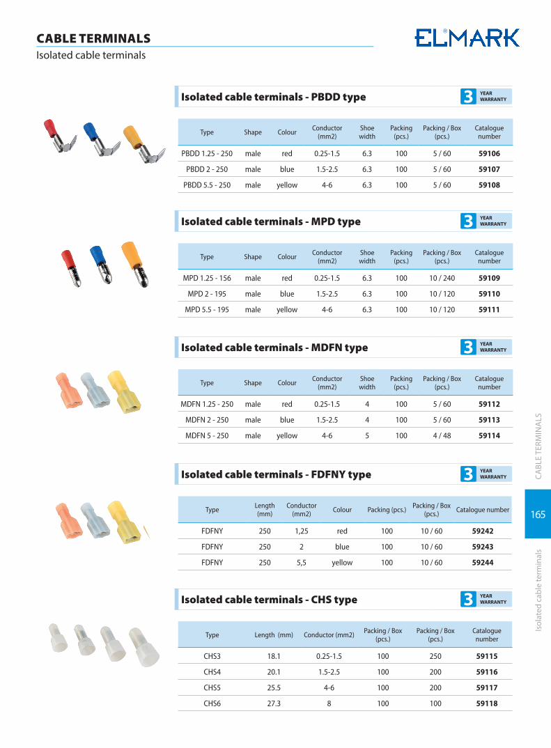
165
CA
BLE
TERM
INA
LSIs
olat
ed c
able
term
inal
s
CABLE TERMINALSIsolated cable terminals
Isolated cable terminals - PBDD type 3 YEAR WARRANTY
Type Shape Colour Conductor (mm2)
Shoewidth
Packing (pcs.)
Packing / Box (pcs.)
Catalogue number
PBDD 1.25 - 250 male red 0.25-1.5 6.3 100 5 / 60 59106
PBDD 2 - 250 male blue 1.5-2.5 6.3 100 5 / 60 59107
PBDD 5.5 - 250 male yellow 4-6 6.3 100 5 / 60 59108
Isolated cable terminals - MPD type 3 YEAR WARRANTY
Type Shape Colour Conductor (mm2)
Shoewidth
Packing (pcs.)
Packing / Box (pcs.)
Catalogue number
MPD 1.25 - 156 male red 0.25-1.5 6.3 100 10 / 240 59109
MPD 2 - 195 male blue 1.5-2.5 6.3 100 10 / 120 59110
MPD 5.5 - 195 male yellow 4-6 6.3 100 10 / 120 59111
Isolated cable terminals - MDFN type 3 YEAR WARRANTY
Type Shape Colour Conductor (mm2)
Shoewidth
Packing (pcs.)
Packing / Box (pcs.)
Catalogue number
MDFN 1.25 - 250 male red 0.25-1.5 4 100 5 / 60 59112
MDFN 2 - 250 male blue 1.5-2.5 4 100 5 / 60 59113
MDFN 5 - 250 male yellow 4-6 5 100 4 / 48 59114
Isolated cable terminals - FDFNY type 3 YEAR WARRANTY
Type Length (mm)
Conductor (mm2) Colour Packing (pcs.) Packing / Box
(pcs.) Catalogue number
FDFNY 250 1,25 red 100 10 / 60 59242
FDFNY 250 2 blue 100 10 / 60 59243
FDFNY 250 5,5 yellow 100 10 / 60 59244
Isolated cable terminals - CHS type 3 YEAR WARRANTY
Type Length (mm) Conductor (mm2) Packing / Box (pcs.)
Packing / Box (pcs.)
Catalogue number
CHS3 18.1 0.25-1.5 100 250 59115
CHS4 20.1 1.5-2.5 100 200 59116
CHS5 25.5 4-6 100 200 59117
CHS6 27.3 8 100 100 59118

CABLE INSTALATION SYSTEMCABLE
INSTALATION
Plastic cable trunking | 168
Plastic cable trunking accessories | 169
Cable support systems | 172
Distribution boxes | 180
Waterproof junction boxes | 182

168
CA
BLE
INST
ALL
ATIO
N S
YSTE
MS
Plas
tic c
able
trun
king
CABLE INSTALLATION SYSTEMS Plastic cable trunking
Plastic cable trunking CT2 3 YEAR WARRANTY
Cable trunkings are practical solution of organizing power and communication cables in office and residential buildings. They increase the reliability in operation of the electrical systems and allow quick adaptation if nec-essary to rearrange the interior. Fast and simple installation. In combination with a wide range of accessories, building irregularities are quickly overcome. Non- flammable material, easy to cut and paint.
Type Size(mm) Length Colour Packing (pcs)
Catalogue number
PLASTIC CABLE TRUNKING CT2 12x12 2m white 100 5621212
PLASTIC CABLE TRUNKING CT2 15X10 2m white 100 5621510
PLASTIC CABLE TRUNKING CT2 16X16 2m white 100 5621616
PLASTIC CABLE TRUNKING CT2 25X16 2m white 80 5622516
PLASTIC CABLE TRUNKING CT2 25X25 2m white 50 5622525
PLASTIC CABLE TRUNKING CT2 40X16 2m white 50 5624016
PLASTIC CABLE TRUNKING CT2 40X25 2m white 50 5624025
PLASTIC CABLE TRUNKING CT2 40X40 2m white 40 5624040
PLASTIC CABLE TRUNKING CT2 60X40 2m white 30 5626040
PLASTIC CABLE TRUNKING CT2 60X60 2m white 32 5626060
PLASTIC CABLE TRUNKING CT2 80X40 2m white 18 5628040
PLASTIC CABLE TRUNKING CT2 80X60 2m white 24 5628060
PLASTIC CABLE TRUNKING CT2 100X40 2m white 16 56210040
PLASTIC CABLE TRUNKING CT2 100X60 2m white 16 56210060
Switches and sockets frames for cable trunking 3 YEAR WARRANTY
Cable trunking frames are decorative solution for installation of switches and sockets on places where their normal mounting is not possible. The assembly set includes subframe and main white frame. Universal sizes, suitable for mounting of switches and sockets from different manufacturers. Single, double and triple frames are offered.
Type Used for cable trunking Colour Packing (pcs)
Catalogue number
SINGLE FRAME 100X40/100X60 White 20 562100441
DOUBLE FRAME 100X40/100X60 White 14 562100442
TRIPLE FRAME 100X40/100X60 White 5 562100443
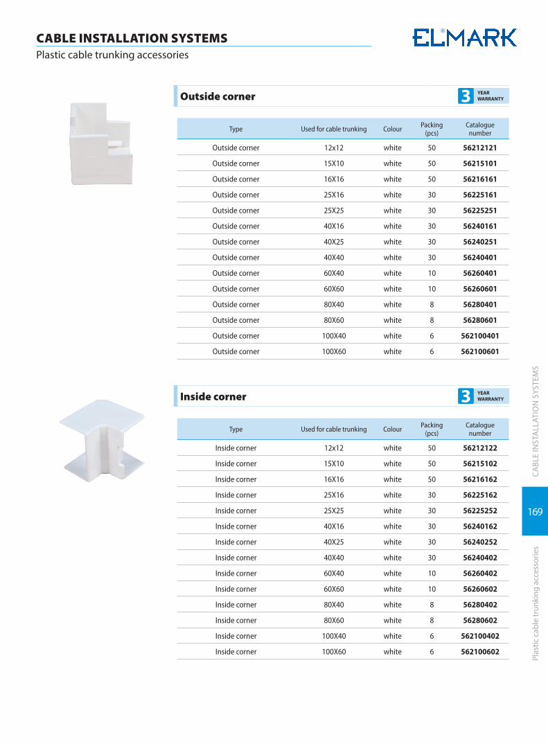
169
CABLE INSTALLATION SYSTEMS Plastic cable trunking accessories
CA
BLE
INST
ALL
ATIO
N S
YSTE
MS
Plas
tic c
able
trun
king
acc
esso
ries
Outside corner 3 YEAR WARRANTY
Type Used for cable trunking Colour Packing (pcs)
Catalogue number
Outside corner 12x12 white 50 56212121
Outside corner 15X10 white 50 56215101
Outside corner 16X16 white 50 56216161
Outside corner 25X16 white 30 56225161
Outside corner 25X25 white 30 56225251
Outside corner 40X16 white 30 56240161
Outside corner 40X25 white 30 56240251
Outside corner 40X40 white 30 56240401
Outside corner 60X40 white 10 56260401
Outside corner 60X60 white 10 56260601
Outside corner 80X40 white 8 56280401
Outside corner 80X60 white 8 56280601
Outside corner 100X40 white 6 562100401
Outside corner 100X60 white 6 562100601
Inside corner 3 YEAR WARRANTY
Type Used for cable trunking Colour Packing (pcs)
Catalogue number
Inside corner 12x12 white 50 56212122
Inside corner 15X10 white 50 56215102
Inside corner 16X16 white 50 56216162
Inside corner 25X16 white 30 56225162
Inside corner 25X25 white 30 56225252
Inside corner 40X16 white 30 56240162
Inside corner 40X25 white 30 56240252
Inside corner 40X40 white 30 56240402
Inside corner 60X40 white 10 56260402
Inside corner 60X60 white 10 56260602
Inside corner 80X40 white 8 56280402
Inside corner 80X60 white 8 56280602
Inside corner 100X40 white 6 562100402
Inside corner 100X60 white 6 562100602

170
CABLE INSTALLATION SYSTEMS Plastic cable trunking accessories
CA
BLE
INST
ALL
ATIO
N S
YSTE
MS
Plas
tic c
able
trun
king
acc
esso
ries
T- corner 3 YEAR WARRANTY
Type Used for cable trunking Colour Packing (pcs)
Catalogue number
T- corner 12x12 white 50 56212123
T- corner 15X10 white 50 56215103
T- corner 16X16 white 50 56216163
T- corner 25X16 white 20 56225163
T- corner 25X25 white 20 56225253
T- corner 40X16 white 30 56240163
T- corner 40X25 white 30 56240253
T- corner 40X40 white 30 56240403
T- corner 60X40 white 16 56260403
T- corner 60X60 white 16 56260603
T- corner 80X40 white 8 56280403
T- corner 80X60 white 8 56280603
T- corner 100X40 white 8 562100403
T- corner 100X60 white 8 562100603
L- corner 3 YEAR WARRANTY
Type Used for cable trunking Colour Packing (pcs)
Catalogue number
L- corner 12x12 white 50 56212124
L- corner 15X10 white 50 56215104
L- corner 16X16 white 50 56216164
L- corner 25X16 white 30 56225164
L- corner 25X25 white 30 56225254
L- corner 40X16 white 30 56240164
L- corner 40X25 white 30 56240254
L- corner 40X40 white 30 56240404
L- corner 60X40 white 16 56260404
L- corner 60X60 white 16 56260604
L- corner 80X40 white 12 56280404
L- corner 80X60 white 12 56280604
L- corner 100X40 white 8 562100404
L- corner 100X60 white 8 562100604
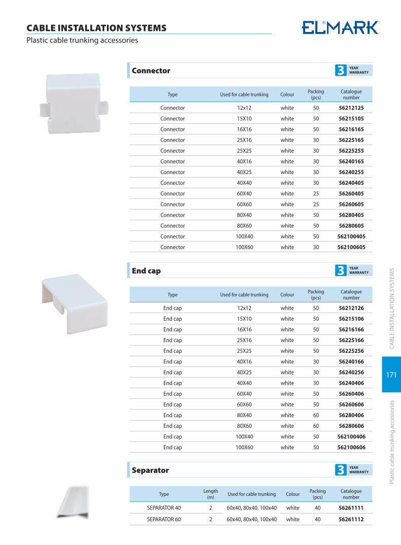
171
CABLE INSTALLATION SYSTEMS Plastic cable trunking accessories
CA
BLE
INST
ALL
ATIO
N S
YSTE
MS
Plas
tic c
able
trun
king
acc
esso
ries
Connector 3 YEAR WARRANTY
Type Used for cable trunking Colour Packing (pcs)
Catalogue number
Connector 12x12 white 50 56212125
Connector 15X10 white 50 56215105
Connector 16X16 white 50 56216165
Connector 25X16 white 30 56225165
Connector 25X25 white 30 56225255
Connector 40X16 white 30 56240165
Connector 40X25 white 30 56240255
Connector 40X40 white 30 56240405
Connector 60X40 white 25 56260405
Connector 60X60 white 25 56260605
Connector 80X40 white 50 56280405
Connector 80X60 white 50 56280605
Connector 100X40 white 50 562100405
Connector 100X60 white 30 562100605
End cap 3 YEAR WARRANTY
Type Used for cable trunking Colour Packing (pcs)
Catalogue number
End cap 12x12 white 50 56212126
End cap 15X10 white 50 56215106
End cap 16X16 white 50 56216166
End cap 25X16 white 50 56225166
End cap 25X25 white 50 56225256
End cap 40X16 white 30 56240166
End cap 40X25 white 30 56240256
End cap 40X40 white 30 56240406
End cap 60X40 white 50 56260406
End cap 60X60 white 50 56260606
End cap 80X40 white 60 56280406
End cap 80X60 white 60 56280606
End cap 100X40 white 50 562100406
End cap 100X60 white 50 562100606
Separator 3 YEAR WARRANTY
Type Length (m) Used for cable trunking Colour Packing
(pcs)Catalogue
number
SEPARATOR 40 2 60x40, 80x40, 100x40 white 40 56261111
SEPARATOR 60 2 60x40, 80x40, 100x40 white 40 56261112

172
CA
BLE
INST
ALL
ATIO
N S
YSTE
MS
Plas
tic c
able
trun
king
CABLE INSTALLATION SYSTEMS Plastic cable trunking
Plastic cable trunking self-adhesive 3 YEAR WARRANTY
Type Size(mm) Length Colour Packing m/pcs
Catalogue number
Plastic cable trunking self-adhesive
12x12 2m White 250/125 5621212A
15x10 2m White 250/125 5621510A
16х16 2m White 250/125 5621616A
25x16 2m White 100/50 5622516A
25х25 2m white 100/50 5622525A
40x16 2m white 50/25 5624016A
40x25 2m White 80/40 5624025A
40x40 2m White 80/40 5624040A
Plastic cable trunking - Dark Walnut 3 YEAR WARRANTY
Type Size(mm) Length Colour Packing m/pcs
Catalogue number
Plastic cable trunking dark walnut
12x12 2m Dark walnut 250/125 5621212DW
15x10 2m Dark walnut 250/125 5621510DW
16x16 2m Dark walnut 250/125 5621616DW
25x16 2m Dark walnut 150/75 5622516DW
25x25 2m Dark walnut 100/50 5622525DW
40x25 2m Dark walnut 80/40 5624025DW
Plastic cable trunking - Light Beech 3 YEAR WARRANTY
Type Size(mm) Length Colour Packing m/pcs
Catalogue number
Plastic cable trunking light beech
12x12 2m Light Beech 250/125 5621212LB
15x10 2m Light Beech 250/125 5621510LB
16x16 2m Light Beech 250/125 5621616LB
25x16 2m Light Beech 150/75 5622516LB
25x25 2m Light Beech 100/50 5622525LB
40x25 2m Light Beech 80/40 5624025LB
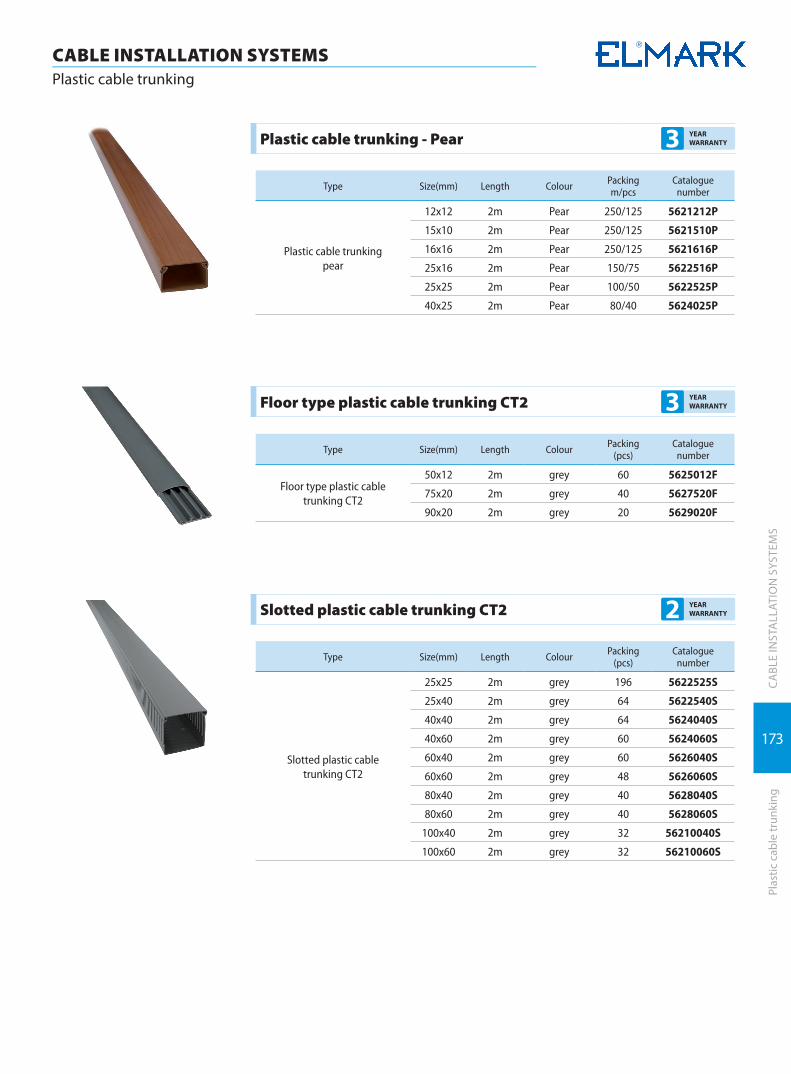
173
CA
BLE
INST
ALL
ATIO
N S
YSTE
MS
Plas
tic c
able
trun
king
CABLE INSTALLATION SYSTEMS Plastic cable trunking
Plastic cable trunking - Pear 3 YEAR WARRANTY
Type Size(mm) Length Colour Packing m/pcs
Catalogue number
Plastic cable trunking pear
12x12 2m Pear 250/125 5621212P
15x10 2m Pear 250/125 5621510P
16x16 2m Pear 250/125 5621616P
25x16 2m Pear 150/75 5622516P
25x25 2m Pear 100/50 5622525P
40x25 2m Pear 80/40 5624025P
Floor type plastic cable trunking CT2 3 YEAR WARRANTY
Type Size(mm) Length Colour Packing (pcs)
Catalogue number
Floor type plastic cable trunking CT2
50x12 2m grey 60 5625012F
75x20 2m grey 40 5627520F
90x20 2m grey 20 5629020F
Slotted plastic cable trunking CT2 2 YEAR WARRANTY
Type Size(mm) Length Colour Packing (pcs)
Catalogue number
Slotted plastic cable trunking CT2
25x25 2m grey 196 5622525S
25x40 2m grey 64 5622540S
40x40 2m grey 64 5624040S
40x60 2m grey 60 5624060S
60x40 2m grey 60 5626040S
60x60 2m grey 48 5626060S
80x40 2m grey 40 5628040S
80x60 2m grey 40 5628060S
100x40 2m grey 32 56210040S
100x60 2m grey 32 56210060S

174
CA
BLE
INST
ALL
ATIO
N S
YSTE
MS
Cabl
e su
ppor
t sys
tem
s
CABLE INSTALLATION SYSTEMS Cable support systems
Self-extinguishing pliable conduits with draw tape EC 3 YEAR WARRANTY
Technical data:Material- technopolymer on PVC base, Self extinguishing V0 degree to UL94 Compresion resistance- 320N Standard- EN 61386-1; EN61386-22 RAL- 7035
Type Inner Diameter Ф (mm)
Outer Diameter Ф (mm) Packing (m) Catalogue number
Self-extinguishing pliable conduits with draw tape
10,7 16 100 500N16
14,1 20 100 500N20
18,2 25 50 500N25
24,3 32 25 500N32
32,3 40 25 500N40
Spiral flexible PVC conduits- UV rays resistant EC 3 YEAR WARRANTY
Technical data:Material (spiral+cover)- shock resistance technopolymer on PVC baseSelf extinguishing V0 degree to UL94Compresion resistance- 320NInstalation temperature: -15/+70Operating temperature: -5/+65Type: UV rays resistance
Type Inner Diameter Ф (mm)
Outer Diameter Ф (mm) Packing (m) Catalogue number
UV flexible pvc conduit
12 16,2 30 500UV12
16 20,2 30 500UV16
20 24,2 30 500UV20
25 29,6 30 500UV25
32 37,2 30 500UV32
Nylon cable draw tape EC 2 YEAR WARRANTY
Type Diameter Ф (mm) Lenght (m) Colour Packing (pcs) Catalogue
number
Nylon cable draw tape3 3 Transparent 1/340 500305
3 5 Transparent 1/120 500315
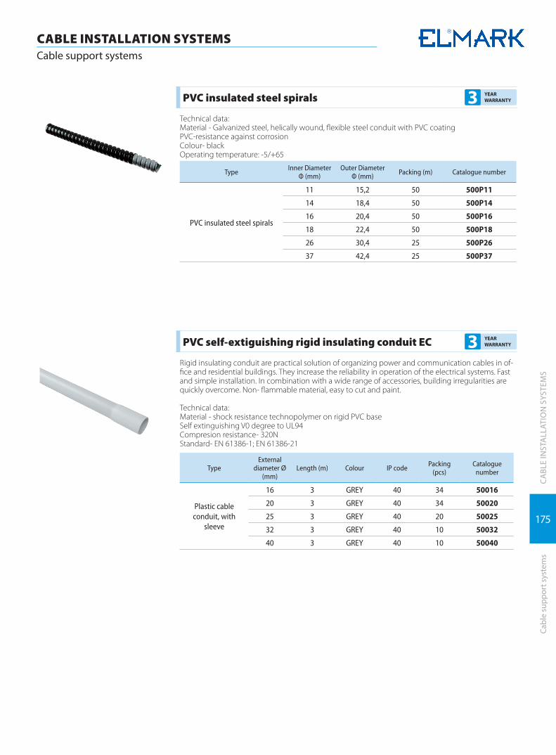
175
CA
BLE
INST
ALL
ATIO
N S
YSTE
MS
Cabl
e su
ppor
t sys
tem
s
CABLE INSTALLATION SYSTEMS Cable support systems
PVC insulated steel spirals 3 YEAR WARRANTY
Technical data:Material - Galvanized steel, helically wound, flexible steel conduit with PVC coatingPVC-resistance against corrosionColour- blackOperating temperature: -5/+65
Type Inner Diameter Ф (mm)
Outer Diameter Ф (mm) Packing (m) Catalogue number
PVC insulated steel spirals
11 15,2 50 500P11
14 18,4 50 500P14
16 20,4 50 500P16
18 22,4 50 500P18
26 30,4 25 500P26
37 42,4 25 500P37
PVC self-extiguishing rigid insulating conduit EC 3 YEAR WARRANTY
Rigid insulating conduit are practical solution of organizing power and communication cables in of-fice and residential buildings. They increase the reliability in operation of the electrical systems. Fast and simple installation. In combination with a wide range of accessories, building irregularities are quickly overcome. Non- flammable material, easy to cut and paint.
Technical data:Material - shock resistance technopolymer on rigid PVC baseSelf extinguishing V0 degree to UL94Compresion resistance- 320NStandard- EN 61386-1; EN 61386-21
Type External
diameter Ø (mm)
Length (m) Colour IP code Packing (pcs)
Catalogue number
Plastic cable conduit, with
sleeve
16 3 GREY 40 34 50016
20 3 GREY 40 34 50020
25 3 GREY 40 20 50025
32 3 GREY 40 10 50032
40 3 GREY 40 10 50040

176
CA
BLE
INST
ALL
ATIO
N S
YSTE
MS
Cabl
e su
ppor
t sys
tem
s
CABLE INSTALLATION SYSTEMS Cable support systems
Accessories for PVC self-extiguishing rigid insulating conduits and flexible spiral conduits, IP 65 EC 3 YEAR
WARRANTY
Technical data: Material- shock resistant technopolymer on PVC baseSelf-extinguishing V0 degree to UL94Glow wire test: up to 960°CO-ring to compensate the conduit tolerancesStandard- EN 61386-1; EN61386-21RAL- 7035
Type Used for cable conduit ф (mm) IP code Colour Packing/Box
(pcs)Catalogue
number
PVC bend flexible
16 65 GREY 50/200 500FB16
20 65 GREY 50/200 500FB20
25 65 GREY 35/140 500FB25
32 65 GREY 20/80 500FB32
Type Used for cable conduit ф (mm) IP code Colour Packing/Box
(pcs)Catalogue
number
PVC bend 90°
16 65 GREY 100/1000 500BB16
20 65 GREY 50/600 500BB20
25 65 GREY 25/300 500BB25
32 65 GREY 100 500BB32
40 65 GREY 100 500BB40
Type Used for cable conduit ф (mm) IP code Colour Packing/Box
(pcs)Catalogue
number
Conduit-conduit PVC joint
16 65 GREY 10/350 500CM16
20 65 GREY 10/350 500CM20
25 65 GREY 10/200 500CM25
32 65 GREY 10/100 500CM32
40 65 GREY 5/80 500CM40
Type Used for cable conduit ф (mm) IP code Colour Packing/Box
(pcs)Catalogue
number
Conduit-box PVC joint
16 65 GREY 10/350 500CB16
20 65 GREY 10/350 500CB20
25 65 GREY 10/200 500CB25
32 65 GREY 10/100 500CB32
40 65 GREY 5/80 500CB40
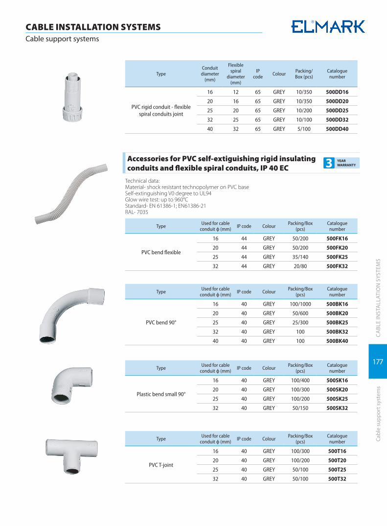
177
CA
BLE
INST
ALL
ATIO
N S
YSTE
MS
Cabl
e su
ppor
t sys
tem
s
CABLE INSTALLATION SYSTEMS Cable support systems
Type Conduit
diameter (mm)
Flexible spiral
diameter (mm)
IP code Colour Packing/
Box (pcs)Catalogue
number
PVC rigid conduit - flexible spiral conduits joint
16 12 65 GREY 10/350 500DD16
20 16 65 GREY 10/350 500DD20
25 20 65 GREY 10/200 500DD25
32 25 65 GREY 10/100 500DD32
40 32 65 GREY 5/100 500DD40
Accessories for PVC self-extiguishing rigid insulating conduits and flexible spiral conduits, IP 40 EC 3 YEAR
WARRANTY
Technical data:Material- shock resistant technopolymer on PVC baseSelf-extinguishing V0 degree to UL94Glow wire test: up to 960°CStandard- EN 61386-1; EN61386-21RAL- 7035
Type Used for cable conduit ф (mm) IP code Colour Packing/Box
(pcs)Catalogue
number
PVC bend flexible
16 44 GREY 50/200 500FK16
20 44 GREY 50/200 500FK20
25 44 GREY 35/140 500FK25
32 44 GREY 20/80 500FK32
Type Used for cable conduit ф (mm) IP code Colour Packing/Box
(pcs)Catalogue
number
PVC bend 90°
16 40 GREY 100/1000 500BK16
20 40 GREY 50/600 500BK20
25 40 GREY 25/300 500BK25
32 40 GREY 100 500BK32
40 40 GREY 100 500BK40
Type Used for cable conduit ф (mm) IP code Colour Packing/Box
(pcs)Catalogue
number
Plastic bend small 90°
16 40 GREY 100/400 500SK16
20 40 GREY 100/300 500SK20
25 40 GREY 100/200 500SK25
32 40 GREY 50/150 500SK32
Type Used for cable conduit ф (mm) IP code Colour Packing/Box
(pcs)Catalogue
number
PVC T-joint
16 40 GREY 100/300 500T16
20 40 GREY 100/200 500T20
25 40 GREY 50/100 500T25
32 40 GREY 50/100 500T32

178
CA
BLE
INST
ALL
ATIO
N S
YSTE
MS
Cabl
e su
ppor
t sys
tem
s
CABLE INSTALLATION SYSTEMS Cable support systems
Type Used for cable conduit ф (mm) IP code Colour Packing/Box
(pcs)Catalogue
number
PVC coupling
16 40 GREY 100/1200 500C16
20 40 GREY 100/800 500C20
25 40 GREY 50/500 500C25
32 40 GREY 25/250 500C32
40 40 GREY 25/150 500C40
Type Used for cable conduit ф (mm) Colour Packing/Box
(pcs)Catalogue
number
PVC conduit clips
16 GREY 100/1500 500CC16
20 GREY 100/1000 500CC20
25 GREY 100/1000 500CC25
32 GREY 100/800 500CC32
40 GREY 50/400 500CC40
Type Used for cable conduit ф (mm) Colour Packing/Box
(pcs)Catalogue
number
PVC conduit clips with plug and steel screw
16 GREY 100/1000 500CS16
20 GREY 100/1000 500CS20
25 GREY 100/800 500CS25
32 GREY 50/400 500CS32
Type Used for cable conduit ф (mm) Colour Packing/Box
(pcs)Catalogue
number
PVC collar conduit clips
16 GREY 100/1000 500CО16
20 GREY 100/1000 500CО20
25 GREY 100/800 500CО25
32 GREY 50/500 500CО32
Type Length (mm) Colour Packing Catalogue number
PVC modular fixing guide for clips 200 GREY 400 500BC
Cable trays and accessories 2 YEAR WARRANTY
The universal cable support systems are used for construction of cable link in closed production premises for direct mounting on even vertical surfaces. They are perforated metal grates and accesso-ries with standard lengths and sizes. They allow quick construction of cable systems with many angles and derivations.
Type Size (mm) Tickness Length (mm)
Catalogue number
CT1 UT CABLE TRAY 40x50 0,8 2500 56050825U
CT1 UT CABLE TRAY 40x100 0,8 2500 56100825U
CT1 UT CABLE TRAY 40x150 0,8 2500 56150825U
CT1 UT CABLE TRAY 40x200 0,8 2500 56200825U
CT1 UT CABLE TRAY 40x300 0,8 2500 56300825U
CT1 UT CABLE TRAY 40x400 0,8 2500 56400825U

179
CA
BLE
INST
ALL
ATIO
N S
YSTE
MS
Cabl
e su
ppor
t sys
tem
s
CABLE INSTALLATION SYSTEMS Cable support systems
Type Size (mm) Tickness Length (mm)
Catalogue number
CT1 UT CABLE TRAY 60x100 0,8 2500 56100826U
CT1 UT CABLE TRAY 60x200 0,8 2500 56200826U
CT1 UT CABLE TRAY 60x300 0,8 2500 56300826U
mountaing scheme
Type Size (mm) Tickness Length (mm)
Catalogue number
CT1 CABLE TRAY COVER 10x50 0,8 2500 56050825C
CT1 CABLE TRAY COVER 10x100 0,8 2500 56100825C
CT1 CABLE TRAY COVER 10x150 0,8 2500 56150825C
CT1 CABLE TRAY COVER 10x200 0,8 2500 56200825C
CT1 CABLE TRAY COVER 10x300 0,8 2500 56300825C
mountaing scheme
Type Size (mm) Length (mm) Catalogue number
CT1 COUPLER FOR TRAYS WITH THE SAME SIZE 40 250 56250C
mountaing scheme
Type Tickness Length (mm)
Catalogue number
CT1 U-HANGING SUPPORT 1,5 100 56100HSW
CT1 U-HANGING SUPPORT 1,5 150 56150HSW
CT1 U-HANGING SUPPORT 1,5 200 56200HSW
CT1 U-HANGING SUPPORT 1,5 300 56300HSW
CT1 U-HANGING SUPPORT 1,5 400 56400HSW
mountaing scheme
Type Tickness Length (mm)
Catalogue number
CT1 HOLDER 1,5 100 56100HOL
CT1 HOLDER 1,5 150 56150HOL
CT1 HOLDER 1,5 200 56200HOL
CT1 HOLDER 1,5 300 56300HOL
mountaing scheme
Type Metric bolt diameters
Length (mm)
Catalogue number
CT1 THREADED HANGING ROD 8 2000 56082
CT1 THREADED HANGING ROD 10 2000 56102

180
CA
BLE
INST
ALL
ATIO
N S
YSTE
MS
Dis
trib
utio
n bo
xes
CABLE INSTALLATION SYSTEMS Distribution boxes
Universal console box for plasterboard 2 YEAR WARRANTY
Type d (mm) Packing (pcs) Catalogue number
console box for plasterboard- Ф65 65 240 19273
Universal console box-flush mounting 2 YEAR WARRANTY
Type d (mm) Packing (pcs) Catalogue number
console box- Ф65 65 300 1927302
Console box multi 2 YEAR WARRANTY
Type d (mm) Packing (pcs) Catalogue number
Console box multi- Ф65 65 250 1927301
Distribution boxes-square type 2 YEAR WARRANTY
Type Size
Packing (pcs) Catalogue numberL W H
Distribution Box 80/80/50 80 80 50 100 1927402
Distribution Box 100/100/50 100 100 50 100 1927401

181
CA
BLE
INST
ALL
ATIO
N S
YSTE
MS
Dis
trib
utio
n bo
xes
CABLE INSTALLATION SYSTEMS Distribution boxes
Distribution boxes for plasterboard-square type 2 YEAR WARRANTY
Type Size
Packing (pcs) Catalogue numberL W H
Distribution Box 80/80/45 80 80 45 100 1927405
Distribution Box 100/100/45 100 100 45 100 1927404
Distribution boxes for plasterboard-round type 2 YEAR WARRANTY
Type d (mm) Packing (pcs) Catalogue number
Distribution Box Ф65 65 240 1927403
Distribution Box Ф70 70 200 1927407
Distribution Box Ф80 80 100 1927409
Distribution boxes - round type 2 YEAR WARRANTY
Type d (mm) Packing (pcs) Catalogue number
Distribution Box Ф70 70 300 1927406
Distribution Box Ф80 80 200 1927408

182
CA
BLE
INST
ALL
ATIO
N S
YSTE
MS
CABLE INSTALLATION SYSTEMS Waterproof junction boxes
Wat
erpr
oof j
unct
ion
boxe
s
Waterproof junction boxes IP44 2 YEAR WARRANTY
Plastic junction boxes with different shapes and dimensions. Designed for cable lines extension or tapping at cable installations laying. Made of ABS material with openings for input - output conduc-tors, with rubber gasket to provide the corresponding IP code. Resistant to chemical, thermal and UV rays. Direct wall mounting with screws.Documentation corresponding to the product:Standard: EN 60670-1
Technical data:* Rated voltage: up to 1000V* Material: ABS* IP code: IP 44
Box typeBox dimensions (mm) Gasket dimen-
sions (mm) IP code Packing / Box Catalogue number
D L W H d C
WB50/50 50 - - 50 22.5 17 44 320 8070
WB80/50 80 - - 50 22.5 17 44 240 8071
WB85/85/50 - 85 85 50 22.5 18.5 44 200 8072

183
CA
BLE
INST
ALL
ATIO
N S
YSTE
MS
CABLE INSTALLATION SYSTEMS Waterproof junction boxes
Wat
erpr
oof j
unct
ion
boxe
s
Waterproof junction boxes IP65 2 YEAR WARRANTY
Box typeBox dimensions (mm)
Hole/pcs IP code Packing / Box
Catalogue number
L W H d
WBG 100/100/70 100 100 70 27 7 65 100 8001
WBG 150/110/70 150 110 70 27 10 65 60 8002
WBG 150/150/70 150 150 70 27 7 65 60 8003
WBG 200/100/70 200 100 70 27 8 65 50 8004
WBG 200/155/80 200 155 80 35 10 65 30 8005
WBG 200/200/80 200 200 80 35 12 65 30 8006
WBG 255/200/80 255 200 80 35 12 65 30 8007
WBG 300/250/120 300 250 120 35 12 65 20 8008
WBG 400/350/120 400 350 120 35 16 65 5 8009
Waterproof junction boxes IP66 with transparent cover 2 YEAR WARRANTY
Box typeBox dimensions (mm)
IP code Packing / Box Catalogue number
L W H
WBT 65/95/55 65 95 55 66 200 8010
WBT 100/100/50 100 100 50 66 150 8011
WBT 80/110/70 80 110 70 66 100 8012
WBT 80/130/85 80 130 85 66 100 8013
WBT 80/180/70 80 180 70 66 86 8014
WBT 80/250/85 80 250 85 66 60 8015
WBT 125/125/75 125 125 75 66 48 8016
WBT 125/175/100 125 175 100 66 40 8017
WBT 150/200/100 150 200 100 66 24 8018
WBT 150/250/130 150 250 130 66 18 8019
WBT 200/200/130 200 200 130 66 27 8020
WBT 280/190/130 280 190 130 66 18 8021

ACCESSORIES
ACCESSORIES

Consummative | 186
Heat shrinkage tubes | 192
Terminal blocks | 193

186
ACCESSORIESConsummative
ACC
ESSO
RIES
Cons
umm
ativ
e
Supply busbar 3 YEAR WARRANTY
Functions: � enables the supply of a group of conductors � provides simultaneous supply � conducting section – electrotechnical copper � insulation of the conducting section
Technical data: � Rated operating voltage: 230/400V � Isolating voltage: 500V � Abnormal heating wear resistance and fire of the outer parts: 960°С/3sec. � Rated current (phase): 63/100A
Connecting: � to the joining terminal of the breaker
Type(copper busbar)
Length (m)
Poles(number)
In with one point
of power supply
In with two points
of power supply
Packing / Box(pcs)
Catalogue number
1P 63 1 54 63А 90А 20 / 100 14163
1P 100 1 54 100A 120A 20 / 100 14190
2P 63 1 28 63A 90A 10 / 50 14263
3P 63 1 18 63А 90А 6 / 30 14363
3P 100 1 18 100A 120A 5 / 50 14390
DP 1N 1 56 63A 90A 10 / 50 14463
C100 1P 1 - 125A 150A 20 / 100 14190T
C100 2P 1 - 125A 150A 10 / 50 14290T
C100 3P 1 - 125A 159A 5 / 20 14390T
U 1P 63 1 54 63A 90A 20 / 100 14163U
U 2P 63 1 28 63A 90A 10 / 50 14263U
U 3P 63 1 18 63A 90A 6 / 30 14363U
U 4P 63 1 13 63A 90A 5 / 20 14463U
Zero rails 3 YEAR WARRANTY
They represent a brass rail with rectangular section with factory made openings for the conductors and bolts for clamping of the conductor. They are offered in types with insulated and non-insulated rail. They are used in the electrical distribution boxes for zeroing and earthing.
Technical data: � Material: brass for the current leading elements � Insulation material: plastic � Colour: gray/blue � Application: general � Ambient temperature: -40 to +65°C
Railtype
Length L (mm)
HeightH (mm)
WidthW (mm) Ø D (mm) Bolt Number of
terminalsPacking / Box
(pcs)Catalogue
number
BRASS 1000 7.8 6 5 M4 54 100 14002
ZEROinsulated
250 - - 5 M4 16 200 14012

187
ACCESSORIESConsummative
ACC
ESSO
RIES
Cons
umm
ativ
e
SP 031
SP 029
Zero terminals 3 YEAR WARRANTY
Rail type L (mm) H (mm) W (mm) M Packing / Box (pcs) Catalogue number
SP 029-4 82.9.4 21.5 12 5x10 10 / 500 14204
SP 029-6 100.9 21.5 12 5x10 10 / 800 14206
SP 029-8 118.9 21.5 12 5x10 20 / 300 14208
SP 029-10 136.9 21.5 12 5x10 20 / 300 14210
SP 029-12 182.4 21.5 12 5x10 20 / 250 14212
SP 031-4 59.5 31.5 12.4 5x10 5 / 400 14304
SP 031-6 76.5 31.5 12.4 5x10 5 / 400 14306
SP 031-8 93 31.5 12.4 5x10 5 / 400 14308
SP 031-10 111 31.5 12.4 5x10 5 / 400 14310
SP 031-12 128 31.5 12.4 5x10 5 / 300 14312
Mounting (DIN) rail 3 YEAR WARRANTY
Functions: � serves for mounting breakers, residual current devices, contactors and other elements � provides a firm fixation of the elements
Technical data: � brass alloy with galvanic cover � factory drilled mounting openings � length up to 1m
Connecting: � with bolts or other fixing elements to the mounting surface
Length (m)
Packing / Box(pcs)
Catalogue number
1m 20 / 100 14001
Insulating mounting terminal - TB25 3 YEAR WARRANTY
Functions: � provides a firm joining of rigid or flexible conductors up to 35mm2 to power supply busbar � provides a firm joining of the power supply conductor to the breaker � provides enough contact surface of the conductor
Technical data: � Brass alloy with galvanic cover � Fabric isolated with plastic cover � Appropriate for joining to copper or aluminum cables � Rated voltage: 230V � Rated current: up to 63A � Isolating voltage: ≥500V � IP code: IP>20 � Section of power supply conductor: up to 35mm2
Connecting: � to the joining terminal of the breaker
Type Section of the conduc-tor (mm2)
Rated currentIn (A)
Packing / Box (pcs)
Catalogue number
TB 25 2.5 to 35 63 20 / 2000 31025

188
ACCESSORIESConsummative
ACC
ESSO
RIES
Cons
umm
ativ
e
Cable glands PG type 3 YEAR WARRANTY
Plastic pipes supplied with the corresponding gaskets and nuts. Designed to provide necessary IP code on the points where conductors pass through the walls of the electric distribution boxes. All cable gland elements are made of high quality plastic (PE) and rubber.
Technical data: � Material: polyethylene (PE) � Colour: gray � Application: general � Ambient temperature: -40 to +65°C � IP code: IP 55
Standard: EN 60 423; 48580-81
Type Overlappingfield T (mm) B (mm) d (mm) D (mm) L1 (mm) L2 (mm) Packing / Box
(pcs)Catalogue
number
PG-7 3.5-6.8 16.3 18 12 6.6 10 22 100 / 4000 500070
PG-9 5-8 18.9 21.7 15.5 8.5 10 25 100 / 4000 500090
PG-11 6-10 21.7 23.5 18.5 10.4 8.5 29 100 / 3000 500110
PG-13.5 7-12 23.6 26.5 20 13 10 29 100 / 2000 500135
PG-16 8-14 26.5 29.3 21.5 14 9 29 100 / 2000 500160
PG-19 9-17 29 32 23 17 12 29 100 / 2000 500190
PG-21 10-18 32.3 35.6 28 19 12 35 100 / 1000 500210
PG-25 15-22 32.6 32.6 29.8 24 13 31 100 / 1000 500250
PG-29 16-24 41.1 45.4 36 26 12.5 40 50 / 500 500290
PG-36 18-28 52 58 46 31.5 12.5 45 50 / 350 500360
PG-42 26-36 57.4 61.9 51 37.6 17.5 47 20 / 200 500420
PG-48 32-39 65.2 70.7 58 43 21 50 20 / 200 500480
Support insulator for low voltage 3 YEAR WARRANTY
Support insulators are used in control and distribution cabinets mounting when bars isolation is required. Provides reliable insulation of live parts.
Technical Specification: � Rated voltage: 1000V � Insulating voltage: 5000 V � Ambient temperature : -40 to +65°C
TypeImpulse voltage
kVStrength Fasting
strength BoltDimmensions (mm)
Packing (pcs.)
Catalogue number H W a ø
SM 25 6 500 6 6 25 30 13 23 10 / 600 31725
SM 30 8 550 8 8 30 32 10 27 10 / 500 31730
SM 35 10 600 10 8 35 32 10 28 10 / 400 31735
SM 40 12 650 12 8 40 40 10 33 10 / 240 31740
SM 51 15 1000 20 8 51 50 12 28 10 / 240 31751
SM 76 25 1500 40 10 76 45 16 34 10 / 120 31776
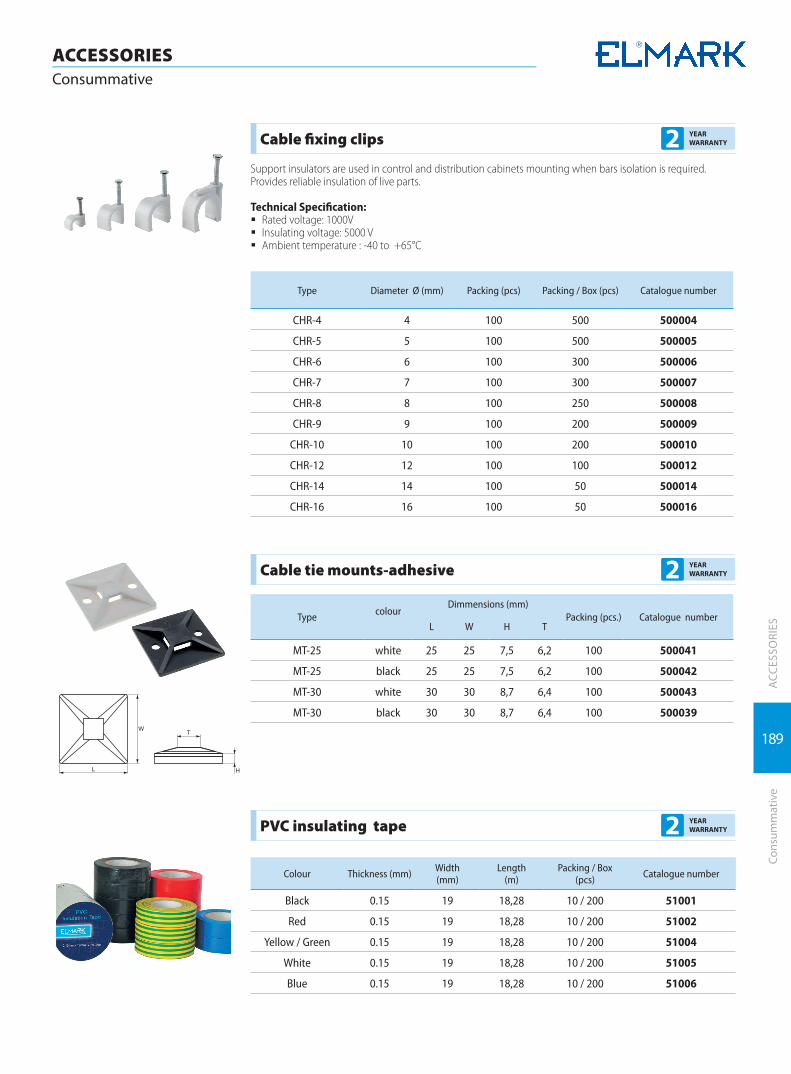
189
ACCESSORIESConsummative
ACC
ESSO
RIES
Cons
umm
ativ
e
Cable fixing clips 2 YEAR WARRANTY
Support insulators are used in control and distribution cabinets mounting when bars isolation is required. Provides reliable insulation of live parts.
Technical Specification: � Rated voltage: 1000V � Insulating voltage: 5000 V � Ambient temperature : -40 to +65°C
Type Diameter Ø (mm) Packing (pcs) Packing / Box (pcs) Catalogue number
CHR-4 4 100 500 500004
CHR-5 5 100 500 500005
CHR-6 6 100 300 500006
CHR-7 7 100 300 500007
CHR-8 8 100 250 500008
CHR-9 9 100 200 500009
CHR-10 10 100 200 500010
CHR-12 12 100 100 500012
CHR-14 14 100 50 500014
CHR-16 16 100 50 500016
Type colourDimmensions (mm)
Packing (pcs.) Catalogue number L W H T
МТ-25 white 25 25 7,5 6,2 100 500041
МТ-25 black 25 25 7,5 6,2 100 500042
МТ-30 white 30 30 8,7 6,4 100 500043
МТ-30 black 30 30 8,7 6,4 100 500039
Cable tie mounts-adhesive 2 YEAR WARRANTY
PVC insulating tape 2 YEAR WARRANTY
Colour Thickness (mm) Width (mm)
Length(m)
Packing / Box(pcs) Catalogue number
Black 0.15 19 18,28 10 / 200 51001
Red 0.15 19 18,28 10 / 200 51002
Yellow / Green 0.15 19 18,28 10 / 200 51004
White 0.15 19 18,28 10 / 200 51005
Blue 0.15 19 18,28 10 / 200 51006
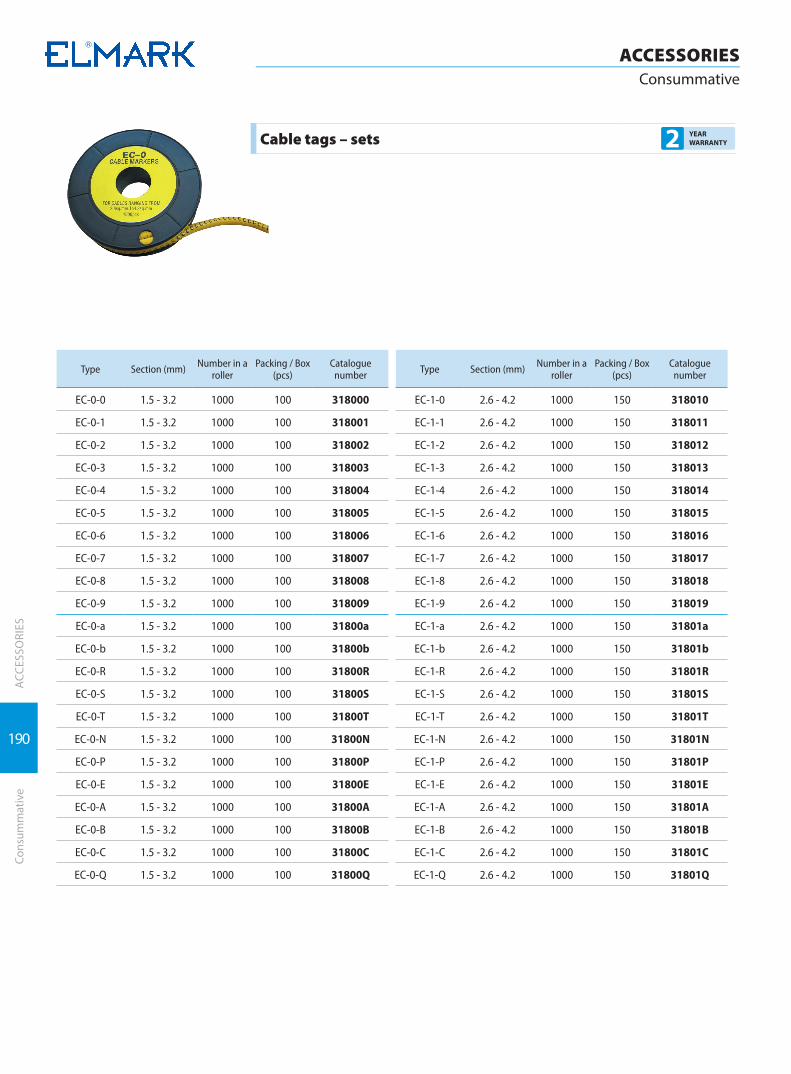
190
ACCESSORIESConsummative
ACC
ESSO
RIES
Cons
umm
ativ
e
Cable tags – sets 2 YEAR WARRANTY
Type Section (mm) Number in a roller
Packing / Box (pcs)
Catalogue number
EC-0-0 1.5 - 3.2 1000 100 318000
EC-0-1 1.5 - 3.2 1000 100 318001
EC-0-2 1.5 - 3.2 1000 100 318002
EC-0-3 1.5 - 3.2 1000 100 318003
EC-0-4 1.5 - 3.2 1000 100 318004
EC-0-5 1.5 - 3.2 1000 100 318005
EC-0-6 1.5 - 3.2 1000 100 318006
EC-0-7 1.5 - 3.2 1000 100 318007
EC-0-8 1.5 - 3.2 1000 100 318008
EC-0-9 1.5 - 3.2 1000 100 318009
EC-0-a 1.5 - 3.2 1000 100 31800a
EC-0-b 1.5 - 3.2 1000 100 31800b
EC-0-R 1.5 - 3.2 1000 100 31800R
EC-0-S 1.5 - 3.2 1000 100 31800S
EC-0-T 1.5 - 3.2 1000 100 31800T
EC-0-N 1.5 - 3.2 1000 100 31800N
EC-0-P 1.5 - 3.2 1000 100 31800P
EC-0-Е 1.5 - 3.2 1000 100 31800E
EC-0-А 1.5 - 3.2 1000 100 31800A
EC-0-B 1.5 - 3.2 1000 100 31800B
EC-0-C 1.5 - 3.2 1000 100 31800C
EC-0-Q 1.5 - 3.2 1000 100 31800Q
Type Section (mm) Number in a roller
Packing / Box (pcs)
Catalogue number
EC-1-0 2.6 - 4.2 1000 150 318010
EC-1-1 2.6 - 4.2 1000 150 318011
EC-1-2 2.6 - 4.2 1000 150 318012
EC-1-3 2.6 - 4.2 1000 150 318013
EC-1-4 2.6 - 4.2 1000 150 318014
EC-1-5 2.6 - 4.2 1000 150 318015
EC-1-6 2.6 - 4.2 1000 150 318016
EC-1-7 2.6 - 4.2 1000 150 318017
EC-1-8 2.6 - 4.2 1000 150 318018
EC-1-9 2.6 - 4.2 1000 150 318019
EC-1-a 2.6 - 4.2 1000 150 31801a
EC-1-b 2.6 - 4.2 1000 150 31801b
EC-1-R 2.6 - 4.2 1000 150 31801R
EC-1-S 2.6 - 4.2 1000 150 31801S
EC-1-T 2.6 - 4.2 1000 150 31801T
EC-1-N 2.6 - 4.2 1000 150 31801N
EC-1-P 2.6 - 4.2 1000 150 31801P
EC-1-Е 2.6 - 4.2 1000 150 31801E
EC-1-А 2.6 - 4.2 1000 150 31801A
EC-1-B 2.6 - 4.2 1000 150 31801B
EC-1-C 2.6 - 4.2 1000 150 31801C
EC-1-Q 2.6 - 4.2 1000 150 31801Q
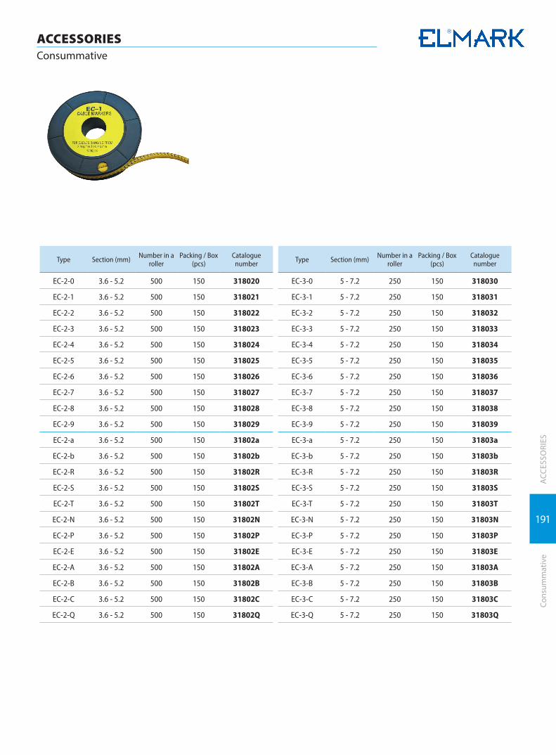
191
ACCESSORIESConsummative
ACC
ESSO
RIES
Cons
umm
ativ
e
Type Section (mm) Number in a roller
Packing / Box (pcs)
Catalogue number
EC-2-0 3.6 - 5.2 500 150 318020
EC-2-1 3.6 - 5.2 500 150 318021
EC-2-2 3.6 - 5.2 500 150 318022
EC-2-3 3.6 - 5.2 500 150 318023
EC-2-4 3.6 - 5.2 500 150 318024
EC-2-5 3.6 - 5.2 500 150 318025
EC-2-6 3.6 - 5.2 500 150 318026
EC-2-7 3.6 - 5.2 500 150 318027
EC-2-8 3.6 - 5.2 500 150 318028
EC-2-9 3.6 - 5.2 500 150 318029
EC-2-a 3.6 - 5.2 500 150 31802a
EC-2-b 3.6 - 5.2 500 150 31802b
EC-2-R 3.6 - 5.2 500 150 31802R
EC-2-S 3.6 - 5.2 500 150 31802S
EC-2-T 3.6 - 5.2 500 150 31802T
EC-2-N 3.6 - 5.2 500 150 31802N
EC-2-P 3.6 - 5.2 500 150 31802P
EC-2-Е 3.6 - 5.2 500 150 31802E
EC-2-А 3.6 - 5.2 500 150 31802A
EC-2-B 3.6 - 5.2 500 150 31802B
EC-2-C 3.6 - 5.2 500 150 31802C
EC-2-Q 3.6 - 5.2 500 150 31802Q
Type Section (mm) Number in a roller
Packing / Box (pcs)
Catalogue number
EC-3-0 5 - 7.2 250 150 318030
EC-3-1 5 - 7.2 250 150 318031
EC-3-2 5 - 7.2 250 150 318032
EC-3-3 5 - 7.2 250 150 318033
EC-3-4 5 - 7.2 250 150 318034
EC-3-5 5 - 7.2 250 150 318035
EC-3-6 5 - 7.2 250 150 318036
EC-3-7 5 - 7.2 250 150 318037
EC-3-8 5 - 7.2 250 150 318038
EC-3-9 5 - 7.2 250 150 318039
EC-3-a 5 - 7.2 250 150 31803a
EC-3-b 5 - 7.2 250 150 31803b
EC-3-R 5 - 7.2 250 150 31803R
EC-3-S 5 - 7.2 250 150 31803S
EC-3-T 5 - 7.2 250 150 31803T
EC-3-N 5 - 7.2 250 150 31803N
EC-3-P 5 - 7.2 250 150 31803P
EC-3-Е 5 - 7.2 250 150 31803E
EC-3-А 5 - 7.2 250 150 31803A
EC-3-B 5 - 7.2 250 150 31803B
EC-3-C 5 - 7.2 250 150 31803C
EC-3-Q 5 - 7.2 250 150 31803Q

192
ACC
ESSO
RIES
ACCESSORIESHeat shrinkage tubes
Hea
t shr
inka
ge tu
bes
Standard: EN 60 684
Heat shrinkage tubes ZDG type 2 YEAR WARRANTY
Thin-wall heat shrinkage tubes are used for insulation of cable connection, at conductors repair to protect the cable head from corrosion, for protection of the cable insulation from water and moisture, for restoring the cable insulation integrity, etc. It is a plastic thin wall pipe which at temperature higher than 120°C shrinks its initial diameter to a certain degree. The material has high temperature and UV rays wear resistance. The material represents the so called permanently netted plastic. This material is obtained as the plastic billet is processed with the help of high energy electron rays so that inner molecular bonds between adjacent molecules are formed. After that the pipe is heated to the boiling point, the pipe inflates, so do the inner molecular bonds. Then the pipe is sharply refrigerated and the molecules stay in the condition of inflated bonds for indefinite long time. Heating the pipe repeatedly (after being mounted to
the given cable) the crystals melt again but due to the net structure, they resume the initial pipe diameter and take the form of the cable, pressing it and not allowing the moisture to get under the pipe. Technical data:
� Material: triple cross - linked polyolefin � Colours: blue, black, red, yellow, yellow-green, green,
white � Shrinkage ratio: min 2 : 1 � Ambient temperature: -40 to + 100°C � Shrinkage temperature: min 120°C � Condition of the material during fire exposure: slight
burning � The material does not emit hazardous substances � Insulation resistance: 1х 10 12 Ω/cm � Application: general � Insulating voltage 1000 V
Type D1 (mm) D2 (mm) S (mm) Packing / Box (m) Catalogue number *
ZDG 1 0.5 0.04 200 / 4000 301001x
ZDG 1.5 0.75 0.04 200 / 4000 301115x
ZDG 2 1.0 0.05 200 / 4000 301002x
ZDG 3 1.5 0.05 200 / 2000 301003x
ZDG 4 2.0 0.08 100 / 1700 301004x
ZDG 5 2.5 0.08 100 / 1200 301005x
ZDG 6 3.0 0.08 100 / 1000 301006x
ZDG 7 3.5 0.08 100 / 1000 301007x
ZDG 8 4.0 0.08 100 / 1500 301008x
ZDG 9 4.5 0.08 100 / 1500 301009x
ZDG 10 5.0 0.08 100 / 1500 301010x
ZDG 11 5.5 0.08 100 / 1500 301011x
ZDG 12 6.0 0.08 100 / 1200 301012x
ZDG 13 6.5 0.08 100 / 1200 301013x
ZDG 14 7.0 0.08 100 / 1200 301014x
ZDG 15 7.5 0.08 100 / 1200 301015x
ZDG 16 8.0 0.08 100 / 1200 301016x
ZDG 18 9.0 0.08 50 / 600 301018x
ZDG 20 10 0.08 50 / 500 301020x
ZDG 22 11 0.08 50 / 500 301022x
ZDG 25 12.5 0.08 25 / 600 301025x
ZDG 28 14 0.08 25 / 300 301028x
ZDG 30 15 0.08 25 / 300 301030x
ZDG 35 17.5 0.08 25 / 300 301035x
ZDG 40 20 0.08 25 / 250 301040x
ZDG 50 25 0.08 25 / 200 301050x
ZDG 60 30 0.08 25 / 300 301060x
ZDG 70 35 0.08 25 / 250 301070x
ZDG 80 40 0.08 25 / 100 301080x
ZDG 90 45 0.08 25 / 150 301090x
ZDG 100 50 0.08 25 / 100 301100x
ZDG 120 60 0.08 25 / 200 301120x
ZDG 150 75 0.08 25 / 100 301150x
Note: * At orders after the catalogue number of the corresponding diameter a letter showing the colour must be added: B – blue; R – red; K - black; G - green; Y – yellow;
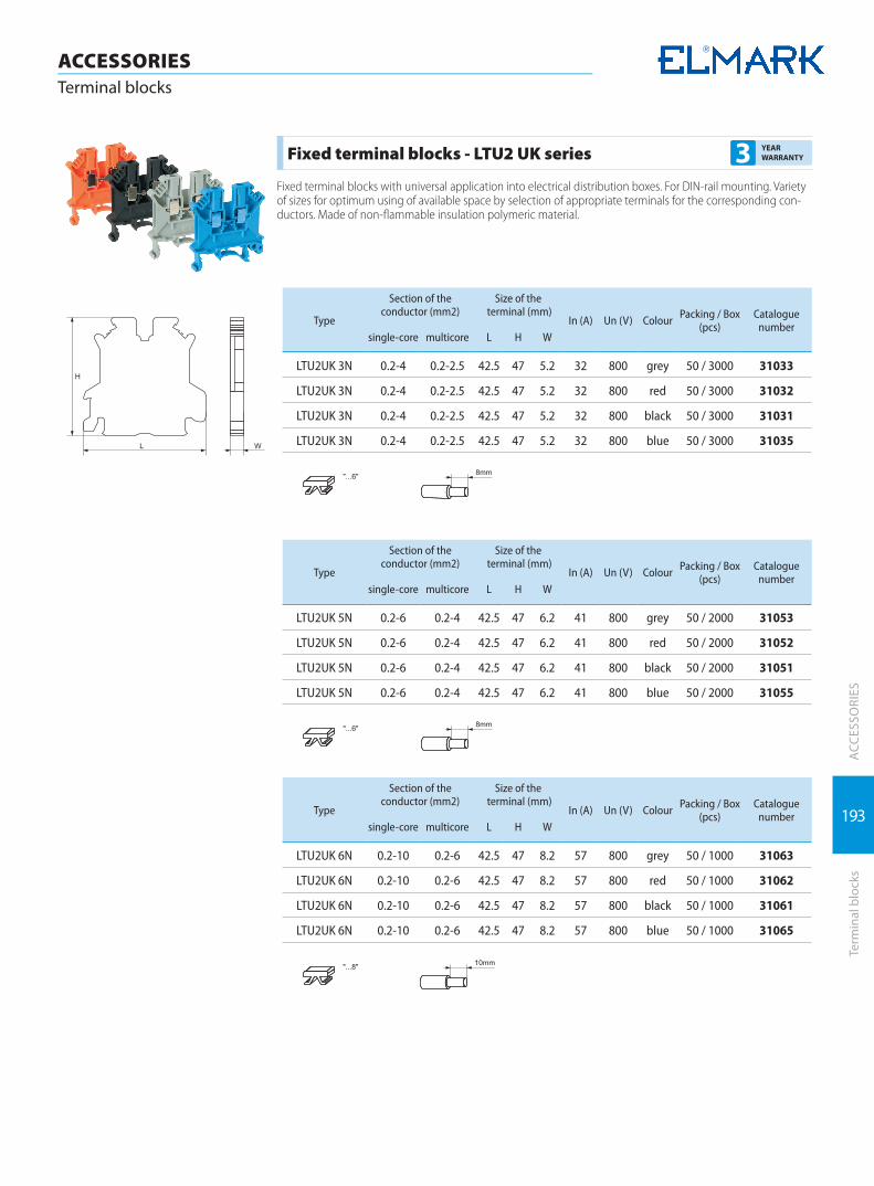
193
ACC
ESSO
RIES
Term
inal
blo
cks
ACCESSORIESTerminal blocks
Fixed terminal blocks - LTU2 UK series 3 YEAR WARRANTY
Fixed terminal blocks with universal application into electrical distribution boxes. For DIN-rail mounting. Variety of sizes for optimum using of available space by selection of appropriate terminals for the corresponding con-ductors. Made of non-flammable insulation polymeric material.
Type
Section of the conductor (mm2)
Size of the terminal (mm)
In (А) Un (V) Colour Packing / Box (pcs)
Catalogue number
single-core multicore L H W
LTU2UK 3N 0.2-4 0.2-2.5 42.5 47 5.2 32 800 grey 50 / 3000 31033
LTU2UK 3N 0.2-4 0.2-2.5 42.5 47 5.2 32 800 red 50 / 3000 31032
LTU2UK 3N 0.2-4 0.2-2.5 42.5 47 5.2 32 800 black 50 / 3000 31031
LTU2UK 3N 0.2-4 0.2-2.5 42.5 47 5.2 32 800 blue 50 / 3000 31035
Type
Section of the conductor (mm2)
Size of the terminal (mm)
In (А) Un (V) Colour Packing / Box (pcs)
Catalogue number
single-core multicore L H W
LTU2UK 5N 0.2-6 0.2-4 42.5 47 6.2 41 800 grey 50 / 2000 31053
LTU2UK 5N 0.2-6 0.2-4 42.5 47 6.2 41 800 red 50 / 2000 31052
LTU2UK 5N 0.2-6 0.2-4 42.5 47 6.2 41 800 black 50 / 2000 31051
LTU2UK 5N 0.2-6 0.2-4 42.5 47 6.2 41 800 blue 50 / 2000 31055
Type
Section of the conductor (mm2)
Size of the terminal (mm)
In (А) Un (V) Colour Packing / Box (pcs)
Catalogue number
single-core multicore L H W
LTU2UK 6N 0.2-10 0.2-6 42.5 47 8.2 57 800 grey 50 / 1000 31063
LTU2UK 6N 0.2-10 0.2-6 42.5 47 8.2 57 800 red 50 / 1000 31062
LTU2UK 6N 0.2-10 0.2-6 42.5 47 8.2 57 800 black 50 / 1000 31061
LTU2UK 6N 0.2-10 0.2-6 42.5 47 8.2 57 800 blue 50 / 1000 31065

194
ACC
ESSO
RIES
ACCESSORIESTerminal blocks
Term
inal
blo
cks
Type
Section of the conductor (mm2)
Size of the terminal (mm)
In (А) Un (V) Colour Packing / Box (pcs)
Catalogue number
single-core multicore L H W
LTU2UK 10N 0.5-16 0.5-10 42.5 47 10.2 76 800 grey 50 / 1000 31103
LTU2UK 10N 0.5-16 0.5-10 42.5 47 10.2 76 800 red 50 / 1000 31102
LTU2UK 10N 0.5-16 0.5-10 42.5 47 10.2 76 800 black 50 / 1000 31101
LTU2UK 10N 0.5-16 0.5-10 42.5 47 10.2 76 800 blue 50 / 1000 31105
Type
Section of the conductor (mm2)
Size of the terminal (mm)
In (А) Un (V) Colour Packing / Box (pcs)
Catalogue number
single-core multicore L H W
LTU2UIK 16 2.5-25 4-16 42.5 47 12.2 101 800 grey 50 / 1000 31163
LTU2UIK 35 10-35 10-35 55 62 15.2 125 800 grey 20 / 400 31353
Fixed terminal blocks - JD series 3 YEAR WARRANTY
Two-sided insulated fixed terminal blocks designed to connect groundes conductors. Made of non-flammable insulation polymeric material.
Type
Section of the conductor (mm2)
Size of the terminal (mm)
In (А) Un (V) Colour Packing / Box (pcs)
Catalogue number
single-core multicore L H W
5JD 0.2-4 0.2-4 42.5 47 6.2 34 800 yellow-green 50 / 1000 31054
6JD 0.2-10 0.2-6 42.5 47 8.2 37 800 yellow-green 50 / 1000 31064
10JD 0.5-10 0.5-6 42.5 47 8.2 61 800 yellow-green 50 / 1000 31104
16JD 2.5-25 2.5-16 42.5 47 12.2 108 800 yellow-green 50 / 600 31164
35JD 2.5-35 2.5-35 42.5 47 15 135 800 yellow-green 20 / 400 31354
Marking tags - ZB type 2 YEAR WARRANTY
Accessories for marking and separation of different electrical circuits, different voltages and fixing of elements for DIN-rail mounting.
Type Pieces in a strip Colour Size (mm) Packing / Box (pcs) Catalogue number
ZB6 20 white 6 100 / 1200 31906
ZB8 10 white 8 100 / 1200 31908

195
ACC
ESSO
RIES
Term
inal
blo
cks
ACCESSORIESTerminal blocks
End cover 3 YEAR WARRANTY
Type Colour Thickness (mm) Packing / Box (pcs) Catalogue number
EC grey 8 200 / 6000 31901
Universal end fixed pieces E/UK type 3 YEAR WARRANTY
Type Colour Thickness (mm) Packing / Box (pcs) Catalogue number
E/UK grey 5 200 / 2400 31902
Expanding block (connectors) for DIN rail 3 YEAR WARRANTY
They are used for cable power supplies branches from one main conductor to several smaller conductors. Designed for DIN - rail mounting. Presented in different colours according to their usage (blue - null conductor, grey - phase conductor, yellow - green - earthing conductor). Easy to mount, reliable way of connection.
Type
Main Terminal Secondary Terminal
Colour Packing / Box (pcs)
Catalogue numberCurrent
(A)Section (mm2)
Number of terminals
Section (mm2)
FVK35 125 35 4 10 blue 3193541
FVK35 125 35 4 10 grey 3193542
FVK35 125 35 4 10 yellow-green 3193543
FVK50/4 150 50 4 16 blue 3195041
FVK50/4 150 50 4 16 grey 3195042
FVK50/4 150 50 4 16 yellow-green 3195043
FVK 50/6 150 50 6 10 blue 3195061
FVK 50/6 150 50 6 10 grey 3195062
FVK 50/6 150 50 6 10 yellow-green 3195063
FVK 70/6 192 70 6 2x25+4x10 blue 3197061
FVK 70/6 192 70 6 2x25+4x10 grey 3197062
FVK 70/6 192 70 6 2x25+4x10 yellow-green 3197063
FVK70/8 192 70 8 10 blue 3197081
FVK70/8 192 70 8 10 grey 3197082
FVK70/8 192 70 8 10 yellow-green 3197083
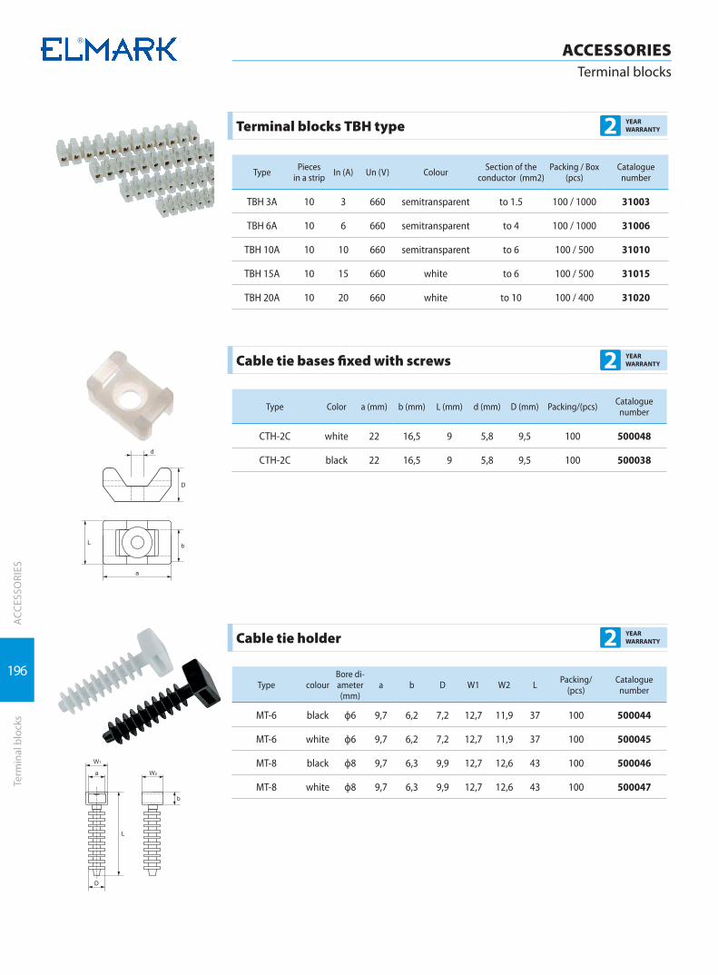
196
ACC
ESSO
RIES
ACCESSORIESTerminal blocks
Term
inal
blo
cks
Terminal blocks TBH type 2 YEAR WARRANTY
Type Pieces in a strip In (А) Un (V) Colour Section of the
conductor (mm2)Packing / Box
(pcs)Catalogue
number
TBH 3A 10 3 660 semitransparent tо 1.5 100 / 1000 31003
TBH 6A 10 6 660 semitransparent tо 4 100 / 1000 31006
TBH 10A 10 10 660 semitransparent tо 6 100 / 500 31010
TBH 15A 10 15 660 white tо 6 100 / 500 31015
TBH 20A 10 20 660 white tо 10 100 / 400 31020
Cable tie bases fixed with screws 2 YEAR WARRANTY
Type Color a (mm) b (mm) L (mm) d (mm) D (mm) Packing/(pcs) Cataloguenumber
CTH-2C white 22 16,5 9 5,8 9,5 100 500048
CTH-2C black 22 16,5 9 5,8 9,5 100 500038
Cable tie holder 2 YEAR WARRANTY
Type colourBore di-ameter (mm)
a b D W1 W2 L Packing/ (pcs)
Cataloguenumber
МТ-6 black ф6 9,7 6,2 7,2 12,7 11,9 37 100 500044
МТ-6 white ф6 9,7 6,2 7,2 12,7 11,9 37 100 500045
МТ-8 black ф8 9,7 6,3 9,9 12,7 12,6 43 100 500046
МТ-8 white ф8 9,7 6,3 9,9 12,7 12,6 43 100 500047
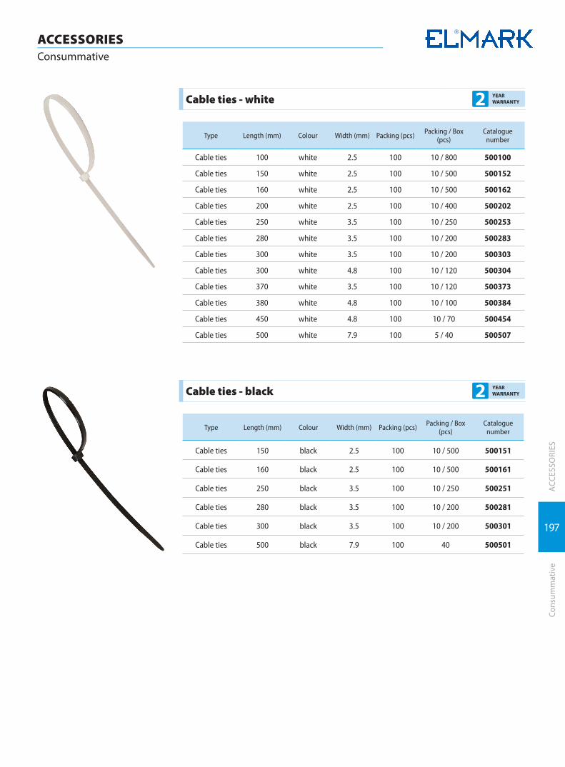
197
ACCESSORIESConsummative
ACC
ESSO
RIES
Cons
umm
ativ
e
Cable ties - white 2 YEAR WARRANTY
Type Length (mm) Colour Width (mm) Packing (pcs) Packing / Box (pcs)
Catalogue number
Cable ties 100 white 2.5 100 10 / 800 500100
Cable ties 150 white 2.5 100 10 / 500 500152
Cable ties 160 white 2.5 100 10 / 500 500162
Cable ties 200 white 2.5 100 10 / 400 500202
Cable ties 250 white 3.5 100 10 / 250 500253
Cable ties 280 white 3.5 100 10 / 200 500283
Cable ties 300 white 3.5 100 10 / 200 500303
Cable ties 300 white 4.8 100 10 / 120 500304
Cable ties 370 white 3.5 100 10 / 120 500373
Cable ties 380 white 4.8 100 10 / 100 500384
Cable ties 450 white 4.8 100 10 / 70 500454
Cable ties 500 white 7.9 100 5 / 40 500507
Cable ties - black 2 YEAR WARRANTY
Type Length (mm) Colour Width (mm) Packing (pcs) Packing / Box (pcs)
Catalogue number
Cable ties 150 black 2.5 100 10 / 500 500151
Cable ties 160 black 2.5 100 10 / 500 500161
Cable ties 250 black 3.5 100 10 / 250 500251
Cable ties 280 black 3.5 100 10 / 200 500281
Cable ties 300 black 3.5 100 10 / 200 500301
Cable ties 500 black 7.9 100 40 500501
TOOLS
TOOLS

Manual meters | 200
Crimping tools | 206
Mechanical cutting tools | 211
Isolated VDE tools | 212

200
TOOLSManual meters
TOO
LSM
anua
l met
ers
Digital multimeter ЕМ5510 3 YEAR WARRANTY
This is a digital device for measuring of humidity, illumination, temperature and all electric values. It features automatic range adjustment, manual value selection. It has an LCD display showing the measured value in digits with the size of 3 ¾ . It is of high accuracy of analogue-digital conversion, precision in measuring and resistance to electro-magnetic interferences. It has an automatic switch off.
Technical features: � DC voltage: 0.4 / 4 / 40 / 400 / 600 V � AC voltage : 4 / 40 / 400 / 600V � DC current: 400μ / 4000μ / 40m / 400m / 10A � AC current: 400μ / 4000μ / 40m / 400m / 10A � Resistance: 400 / 4K / 40K / 400K / 4M / 40MΩ � Capacitors: 4η / 40η / 400η / 4μ / 40μ / 100μF � Frequency: 10 / 100 / 1k / 10k / 100k / 200kHz � Loading cycles: from 0.1% to 99.9% � Temperature: -20° up to 1000°С � Humidity: 30% to 95% � Illumination: 4000 Lux / 40000 Lux � Noise level: 35 to 100dB � Circuit control: yes � Diodes control: yes � Weight: 310 g (including battery) � Battery: 1x9V � Dimensions: 83 х 162 х 47mm
Type Packing (pcs)/ carton
Catalogue number
ЕМ5510 24 5195510
Digital multimeter ЕМ420C 3 YEAR WARRANTY
This is a digital device for measuring of humidity, illumination, temperature and all electric values. It features automatic range adjustment, manual value selection. It has an LCD display showing the measured value in 4 digits with the size of 16 mm. It is of high accuracy of analogue-digital conversion, precision in measuring and resistance to electro-magnetic interferences. It has an automatic switch off.
Technical features: � DC voltage: 200m/ 2 / 20 / 200 / 600 V � AC voltage : 2 / 20 / 200 / 600V � DC current: 200μ / 2000μ / 20m / 200m / 2 / 10A � AC current: 00μ / 2000μ / 20m / 200m / 2 / 10A � Resistance: 200 / 2K / 20K / 200K / 2M / 20MΩ � Temperature: -20° up to 1000°С � Battery test: 1.5 / 3 / 9 / 12 V � Circuit control: yes � Diodes control: yes � Weight: 200 g (including battery) � battery: 3x1.5 V � dimensions: 75 х 158 х 35mmType Packing (pcs)
/ cartonCatalogue
number
ЕМ420C 44 519420

201
TOOLSManual meters
TOO
LSM
anua
l met
ers
Digital multimeter ЕМ3055 3 YEAR WARRANTY
This is a digital device for measuring of all electric values. It features manual range adjustment. It has an LCD display showing the measured value in 4 digits with the size of 3 ½ . It is of high accuracy of analogue-digital conversion, precision in measuring and resistance to electro-magnetic interferences.
Technical features: � DC voltage: 200m/ 2 / 20 / 200 / 1000 V � AC voltage: 2 / 20 / 200 / 750V � DC current: 2m / 20m / 200m / 10A � AC current: 200m / 10A � Resistance: 200 / 2K / 20K / 200K / 2M / 20M / 200MΩ � Capacity: 2000p / 20η / 200η / 20μF � Temperature: 0° up to 1000°С � Battery test: 1.5 / 3 / 9 / 12 V � Transistor test: Vce≈3V , Ib≈10μF � Circuit control: yes � Diodes control: yes � Weight: 495 g (including battery) � battery: 1x9V � dimensions: 97 х 200 х 48mm
Type Packing (pcs)/ carton
Catalogue number
EM3055 20 5193055
Digital multimeter ЕМ3058 3 YEAR WARRANTY
This is a digital device for measuring of temperature and all electric values. It features manual range adjust-ment, manual value selection. It has an LCD display showing the measured value in digits with the size of 3 ¾ . It is of high accuracy of analogue-digital conversion, precision in measuring and resistance to electro-magnet-ic interferences. It has an automatic switch off.
Technical features: � DC voltage: 200m/ 2 / 20 / 200 / 1000 V � AC voltage: 200 m / 2 / 20 / 200 / 750V � DC current: 20μ / 200 μ / 2m / 200m / 10A � AC current: 20μ / 200μ / 2m / 200m / 2 / 10A � Resistance: 200 / 2K / 20K / 200K / 2M / 20M / 200MΩ � Capacitors: 2η / 20η / 200η / 2μ / 20μF � Frequency: 20kHz to 2000kHz � Loading cycles: 0.1% to 99.9% � Temperature: 0° up to 1000°С � Logical level: High > 2.0 V; Low < 0.8 V � Circuit control: yes � Diodes control: yes � Weight: 495 g (including battery) � battery: 1x9V � dimensions: 97 х 200 х 47 mm
Type Packing (pcs)/ carton
Catalogue number
EM3058 20 5193058

202
TOOLSManual meters
TOO
LSM
anua
l met
ers
Digital multimeter ЕМ31 3 YEAR WARRANTY
This is a digital device for measuring of electric values. It features automatic range adjustment, manual value selection. It has an LCD display showing the measured value in 4 digits with the size of 16 mm. It is of high accuracy of analogue-digital conversion, precision in measuring and resistance to electro-magnetic interfer-ences. It has an automatic switch off and low battery indication.
Technical features: � DC voltage: 240m/ 2400m / 24 / 240 / 600 V � AC voltage: 240m/ 2400m / 24 / 240 / 600 V � DC current: 240μ / 2400μ / 24m / 240m / 10A � AC current: 240μ / 2400μ / 24m / 240m / 10A � Resistance: 240 / 2400 / 24K / 240K / 2400K / 24MΩ � Capacity: 25η to 252μF � Frequency: 50 / 500 / 5000 / 50k / 0.5 MHz � Circuit control: yes � Diodes control: yes � Weight: 137 g (including battery) � battery: 2x1.5 V � dimensions: 70 х 126 х 28mmType Packing (pcs)
/ cartonCatalogue
number
EM31 56 519031
Digital multimeter / pen ЕМ3215 3 YEAR WARRANTY
This is a digital device for measuring of electric values in the form of a pen. It features automatic range adjust-ment, manual value selection. It has an LCD display, data retain function, automatic reset, polarity selection, range overload indication. It is of high accuracy of analogue-digital conversion, precision in measuring and resistance to electro-magnetic interferences. It has an automatic switch off and low battery indication and a torch.
Technical features: � DC voltage: 200m/ 2 / 20 / 200 / 600 V � AC voltage: 2 / 20 / 200 / 600V � DC current: 20m to 200mA � AC current: 20m to 200mA � Resistance: 200 / 2K / 20K / 200K / 2M / 20MΩ � Logical level: High > 2.3V; Low < 0.8 V � Circuit control: yes � Diodes control: yes � Weight: 182 g (including battery) � battery: 1x9V � dimensions: 57 х 230 х 30mmType Packing (pcs)
/ cartonCatalogue
number
EM3215 42 5193215

203
TOOLSManual meters
TOO
LSM
anua
l met
ers
Digital clamp meter EM202 3 YEAR WARRANTY
This is a digital clamp meter for measuring of electric values. It features manual range adjustment, manual value selection. It has an LCD display showing the measured value in digits with the size of 3½ mm. It is of high accuracy of analogue-digital conversion, precision in measuring and resistance to electro-magnetic interferences. It has an automatic switch off.
Technical features: � DC voltage: 1000 V � AC voltage: 750V � AC current: 20 / 200 / 1000A � Resistance: 200 kΩ � Temperature: -40° up to 1400°С � Circuit control: yes � Diodes control: yes � Weight: 400 g (including battery) � battery: 1x9V � dimensions: 99 х 250 х 43mm
Type Packing (pcs)/ carton
Catalogue number
EM202 18 519202
Digital clamp meter EM204 3 YEAR WARRANTY
This is a digital clamp meter for measuring of electric values. It features automatic range adjustment, manual value selection. It has an LCD display, low battery indication, overload protection. It is of high accuracy of analogue-digital conversion, precision in measuring and resistance to electro-magnetic interferences. It has an automatic switch off.
Technical features: � DC voltage: 1000 V � AC voltage: 750V � DC current: 200 / 1000A � AC current: 200 / 1000A � Resistance: 200 kΩ � Frequency: 2 kHz � Circuit control: yes � Weight: 400 g (including battery) � battery: 1x9V � dimensions: 99 х 258 х 43mm
Type Packing (pcs)/ carton
Catalogue number
EM204 18 519204
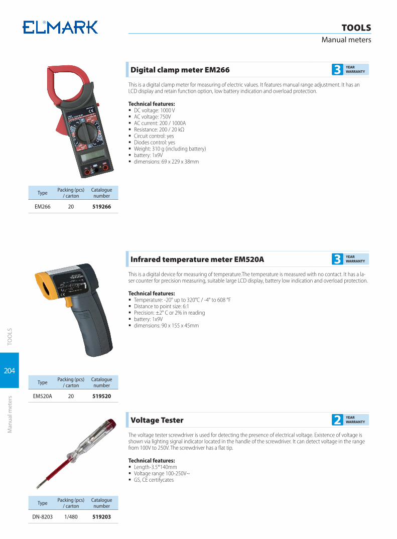
204
TOOLSManual meters
TOO
LSM
anua
l met
ers
Digital clamp meter EM266 3 YEAR WARRANTY
This is a digital clamp meter for measuring of electric values. It features manual range adjustment. It has an LCD display and retain function option, low battery indication and overload protection.
Technical features: � DC voltage: 1000 V � AC voltage: 750V � AC current: 200 / 1000A � Resistance: 200 / 20 kΩ � Circuit control: yes � Diodes control: yes � Weight: 310 g (including battery) � battery: 1x9V � dimensions: 69 х 229 х 38mm
Type Packing (pcs)/ carton
Catalogue number
EM266 20 519266
Infrared temperature meter EM520A 3 YEAR WARRANTY
This is a digital device for measuring of temperature.The temperature is measured with no contact. It has a la-ser counter for precision measuring, suitable large LCD display, battery low indication and overload protection.
Technical features: � Temperature: -20° up to 320°С / -4° to 608 °F � Distance to point size: 6:1 � Precision: ±2° C or 2% in reading � battery: 1x9V � dimensions: 90 х 155 х 45mm
Type Packing (pcs)/ carton
Catalogue number
EM520A 20 519520
Voltage Tester 2 YEAR WARRANTY
The voltage tester screwdriver is used for detecting the presence of electrical voltage. Existence of voltage is shown via lighting signal indicator located in the handle of the screwdriver. It can detect voltage in the range from 100V to 250V. The screwdriver has a flat tip.
Technical features: � Length-3.5*140mm � Voltage range 100-250V~ � GS, CE certifycates
Type Packing (pcs)/ carton
Catalogue number
DN-8203 1/480 519203

205
TOOLSManual meters
TOO
LSM
anua
l met
ers
Phase meter Gk7 3 YEAR WARRANTY
A device indicating phase availability in the system. No contact phase indicator featuring sound and light indication of phase availability.
Technical features: � Voltage range: from 50 to 1000V � Frequency range: from 50 Hz to 500 Hz � dimensions: length – 62mm
Type Packing (pcs)/ carton
Catalogue number
GK7 60 519GK7
Digital detector 4 in 1 series TS530 3 YEAR WARRANTY
This is a device for detecting metals, voltage and live conductors, wooden struts, or piping sections. The device has a 2-meter measuring tape. It features light and sound indication. When an object is located, the display light blinks and marks with increasing position. Once the exact position is located, a light point is marked on the wall through a button.
Technical features: � 2-meter measuring tape � Pen: marking the located detail � Piping section: metal pipe up to 25mm � Wooden struts: 30x30mm � Live conductors detection: 50mm for 90 ~ 250V; 50/60Hz � Weight: 213 g (including battery) � battery: 1x9 V � dimensions: 73 x 180 x 32mmType Packing (pcs)
/ cartonCatalogue
number
TS530 30 519530
Industrial repair kit ETK06A 3 YEAR WARRANTY
A finely packaged repair kit containing four elements in a metal briefcase, sealed with special plastic foam and struts for each instrument.
The kit includes: � Digital multimeter EM420 � Digital clamp-on ammeter EM465 � Phase meter GK7 � Infrared temperature meter EM520A
Type Packing (pcs)/ carton
Catalogue number
ETK06A 6 51906A

206
TOO
LS
TOOLSCrimping tools
Crim
ping
tool
s
Hydraulic crimping pliers HT - 300 type 2 YEAR WARRANTY
Functions: � Crimping of aluminum or copper conductors with cable terminals or bush in the corresponding size
Technical data: � Crimping head turning at 360° which facilitates the crimping of static conductors � Device for automatic following of the effort at crimping completion � Form of the crimping element: hexahedral � Size of the crimping element: 16, 25, 35, 50, 70, 95, 120, 150, 185, 240, 300 mm2 � Section of the crimping conductors:
à - AI conductors - from 16 to 300 mm2 à - Cu conductors – from 16 to 240 mm2
� Element pressing power: 60kN � Width of the element: 17mm � Weight of the instrument: 3.3 kg � Length: 460mm � Used hydraulic oil: #15 (hydraulic oil with viscosity 15) � Metal box for the instrument � A set of congestion hoops for the hydraulic cylinder
Type Packing (pcs)/ carton Catalogue number
HT - 300 2 59300
Hydraulic crimping pliers KYQ-300B type 2 YEAR WARRANTY
Functions: � Crimping of aluminum or copper conductors with cable terminals or bush in the corresponding size
Technical data: � Device for automatic following of the effort at crimping completion � Form of the crimping element: hexahedral � Size of the crimping element: 16, 25, 35, 50, 70, 95, 120, 150, 185, 240, 300 mm2
� Section of the crimping conductors: à - AI conductors - from 16 to 300 mm2
à - Cu conductors – from 16 to 240 mm2
� Element pressing power: 100kN � Width of the element: 22mm � Weight of the instrument: 6.8 kg � Length: 500mm � Used hydraulic oil: #23 (hydraulic oil with viscosity 23) � Metal box for the instrument � A set of congestion hoops for the hydraulic cylinder
Type Packing (pcs)/ carton Catalogue number
KYQ-300B 2 59302

207
TOO
LSCr
impi
ng to
ols
TOOLSCrimping tools
Hydraulic crimping pliers YQK-300 type 2 YEAR WARRANTY
Functions: � Crimping of aluminum or copper conductors with cable terminals or bush in the corresponding size
Technical data: � Form of the crimping element: hexahedral � Size of the crimping element: 10, 16, 25, 35, 50, 70, 95, 120, 150, 185, 240, 300 mm2 � Section of the crimping conductors:
à - AI conductors - from 10 to 300 mm2 à - Cu conductors – from 10 to 240 mm2
� Element pressing power: 100kN � Width of the element: 22mm � Weight of the instrument: 6.3 kg � Length: 500mm � Used hydraulic oil: #15 (hydraulic oil with viscosity 15) � Metal box for the instrument � A set of congestion hoops for the hydraulic cylinder
Type Packing (pcs)/ carton Catalogue number
YQK-300 4 59301
Hydraulic crimping pliers YQK – 50 type 2 YEAR WARRANTY
Functions:Crimping of aluminum or copper conductors with cable terminals or bush in the corresponding sizeTechnical data:
� Form of the crimping element: hexahedral � Size of the crimping element: 4, 6, 10, 16, 25, 35, 50 mm2 � Section of the crimping conductors:
à - AI conductors - from 4 to 50mm2 à - Cu conductors – from 4 to 50 mm2
� Element pressing power: 8T � Width of the element: 10mm � Weight of the instrument: 2.8 kg � Length: 310mm � Used hydraulic oil: #15 (hydraulic oil with viscosity 15) � Metal box for the instrument � A set of congestion hoops for the hydraulic cylinder
Type Packing (pcs)/ carton Catalogue number
YQK – 50 5 59303

208
TOO
LS
TOOLSCrimping tools
Crim
ping
tool
s
Hydraulic punching pliers WK - 8 type 2 YEAR WARRANTY
Functions: � Cutting through openings in sheet metal with gauge up to 3mm without rotary motion
Technical data: � Piercing head turning at 360° � Form of the cutting element: round � Size of the cutting element: Ø 22, 27.5, 34.3, 40, 49, 60.8mm � Piercing capacity:
à - sheet metal 3mm – openings up to Ø 30mm à - sheet metal 2mm – openings up to Ø 60mm
� Element pressing power: 80kN � Thickness of the element: 25mm � Weight of the instrument: 3.5 kg � Used hydraulic oil: #15 (hydraulic oil with viscosity 15) � Metal box for the instrument � A set of congestion hoops for the hydraulic cylinder � Additional set of cutting elements for cable glands – Ø16, 20, 26.2, 32.5, 39, 51, 63 and a square for display
devices 46.5x46.5, 68x68 (ordered additionally); Catalogue number 54002
Type Packing (pcs)/ carton Catalogue number
WK - 8 2 54000
Additional set 2 54002
Hydraulic punching press SYK – 15 type 2 YEAR WARRANTY
Functions: � Cutting through openings in sheet metal with gauge up to 3mm without rotary motion
Technical data: � Protracting piercing head supplied with a hose for the hydraulic oil that gives possibility for piercing open-
ings everywhere on the metal surface � Form of the cutting element:
à - round à - square
� Size of the cutting element: à - square: 32x32mm à - round openings: Ø 22, 27.5, 34.3, 40, 49, 60.8mm
� Piercing capacity: à - sheet metal 3mm – openings up to Ø 60.8mm à - sheet metal 2mm – openings up to Ø 115.5mm à - square opening up to 110x110mm
� Element pressing power: 15T � Thickness of the element: 25mm � Weight of the instrument: 11.5 kg � Used hydraulic oil: #15 (hydraulic oil with viscosity 15) � Metal box for the instrument � A set of congestion hoops for the hydraulic cylinder � Additional set of cutting elements for cable glands – Ø16, 20, 26.2, 32.5, 39, 51, 63 and a square for display
devices 46.5x46.5, 68x68 (ordered additionally); Catalogue number 54002
Type Packing (pcs)/ carton Catalogue number
SYK – 15 2 54001
Additional set 2 54002
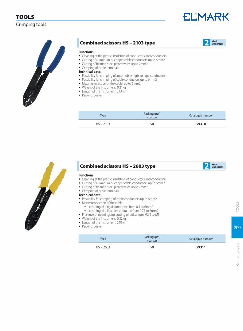
209
TOO
LSCr
impi
ng to
ols
TOOLSCrimping tools
Combined scissors HS – 2103 type 2 YEAR WARRANTY
Functions: � Cleaning of the plastic insulation of conductors and conductors � Cutting of aluminum or copper cable conductors up to 6mm2 � Cutting of bearing steel plated wires up to 2mm2 � Crimping of cable terminals
Technical data: � Possibility for crimping of automobile high voltage conductors � Possibility for crimping of cable conductors up to 6mm2 � Maximum section of the cable: up to 6mm2 � Weight of the instrument: 0.21kg � Length of the instrument: 213mm � Packing: blister
Type Packing (pcs)/ carton Catalogue number
HS – 2103 50 59310
Combined scissors HS – 2603 type 2 YEAR WARRANTY
Functions: � Cleaning of the plastic insulation of conductors and conductors � Cutting of aluminum or copper cable conductors up to 6mm2 � Cutting of bearing steel plated wires up to 2mm2 � Crimping of cable terminals
Technical data: � Possibility for crimping of cable conductors up to 6mm2 � Maximum section of the cable:
à - cleaning of a rigid conductor: from 0.5 to 6mm2 à - cleaning of a flexible conductor: from 0.75 to 6mm2
� Presence of openings for cutting of bolts: from M2.5 to M5 � Weight of the instrument: 0.32kg � Length of the instrument: 240mm � Packing: blister
Type Packing (pcs)/ carton Catalogue number
HS – 2603 50 59311
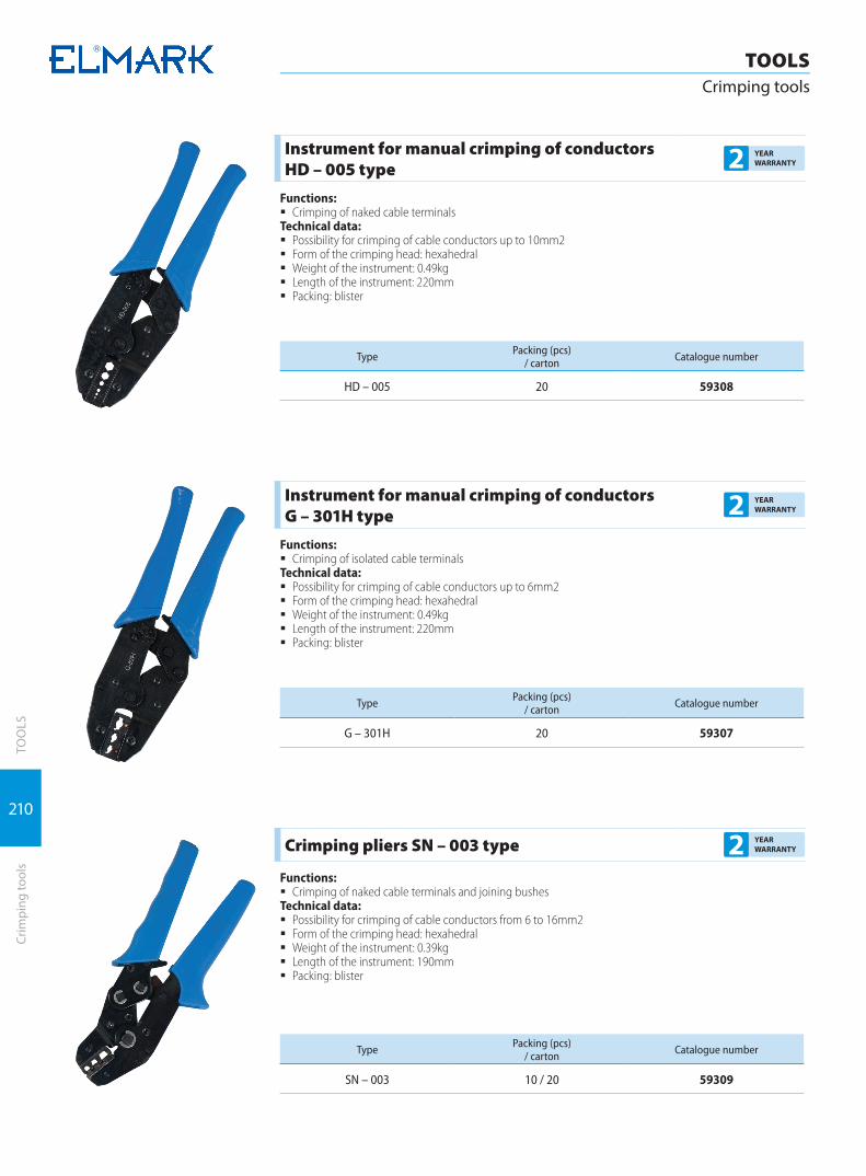
210
TOO
LS
TOOLSCrimping tools
Crim
ping
tool
s
Instrument for manual crimping of conductors HD – 005 type 2 YEAR
WARRANTY
Functions: � Crimping of naked cable terminals
Technical data: � Possibility for crimping of cable conductors up to 10mm2 � Form of the crimping head: hexahedral � Weight of the instrument: 0.49kg � Length of the instrument: 220mm � Packing: blister
Type Packing (pcs)/ carton Catalogue number
HD – 005 20 59308
Instrument for manual crimping of conductors G – 301H type 2 YEAR
WARRANTY
Functions: � Crimping of isolated cable terminals
Technical data: � Possibility for crimping of cable conductors up to 6mm2 � Form of the crimping head: hexahedral � Weight of the instrument: 0.49kg � Length of the instrument: 220mm � Packing: blister
Type Packing (pcs)/ carton Catalogue number
G – 301H 20 59307
Crimping pliers SN – 003 type 2 YEAR WARRANTY
Functions: � Crimping of naked cable terminals and joining bushes
Technical data: � Possibility for crimping of cable conductors from 6 to 16mm2 � Form of the crimping head: hexahedral � Weight of the instrument: 0.39kg � Length of the instrument: 190mm � Packing: blister
Type Packing (pcs)/ carton Catalogue number
SN – 003 10 / 20 59309

211
TOO
LSM
echa
nica
l cut
ting
tool
s
TOOLSMechanical cutting tools
Mechanical cable cutting pliers CC – 325 type 2 YEAR WARRANTY
Functions: � Cutting of aluminum or copper cable conductors � Cutting of conductors with metal bearing core
Technical data: � Maximum section of the cable:
à - for aluminum conductors up to 150mm2 à - for copper conductors up to 150mm2
� Cutting power: 15T � Presence of cutting mechanism type ratchet � Presence of brake of the cutting mechanism � Weight of the instrument: 0.58kg � Length of the instrument: 260mm � Packing: blister
Type Packing (pcs)/ carton Catalogue number
CC – 325 5 / 10 59305
Mechanical cable cutting pliers CC – 400 type 2 YEAR WARRANTY
Functions: � Cutting of aluminum or copper cable conductors � Cutting of conductors with metal bearing core
Technical data: � Maximum section of the cable:
à - for aluminum conductors up to 400mm2 à - for copper conductors up to 350mm2
� Cutting power: 15T � Presence of cutting mechanism type ratchet � Presence of brake of the cutting mechanism � Weight of the instrument: 1.25kg � Length of the instrument: 360mm � Packing: blister
Type Packing (pcs)/ carton Catalogue number
CC – 400 5 59304
Mechanical cable cutting pliers HS – 250 type 2 YEAR WARRANTY
Functions: � Cutting of aluminum or copper cable conductors � Cutting of conductors with metal bearing core
Technical data: � Maximum section of the cable:
à - for aluminum conductors up to 240mm2 à - for copper conductors up to 185mm2
� Weight of the instrument: 1.43kg � Length of the instrument: 540mm � Packing: blister
Type Packing (pcs)/ carton Catalogue number
HS – 250 10 59306
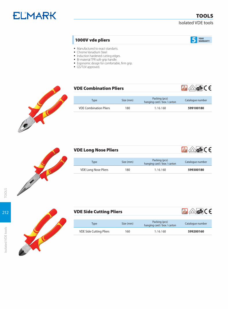
212
TOO
LS
TOOLSIsolated VDE tools
Isol
ated
VD
E to
ols
1000V vde pliers 5 YEAR WARRANTY
� Manufactured to exact standarts. � Chrome Vanadium Steel � Induction hardened cutting edges. � Bi-material TPR soft-grip handle. � Ergonomic design for comfortable, firm grip. � GS/TUV approved.
VDE Combination Pliers
Type Size (mm) Packing (pcs) hanging card / box / carton Catalogue number
VDE Combination Pliers 180 1 / 6 / 60 599100180
VDE Long Nose Pliers
Type Size (mm) Packing (pcs) hanging card / box / carton Catalogue number
VDE Long Nose Pliers 180 1 / 6 / 60 599300180
VDE Side Cutting Pliers
Type Size (mm) Packing (pcs) hanging card / box / carton Catalogue number
VDE Side Cutting Pliers 160 1 / 6 / 60 599200160

213
TOO
LSIs
olat
ed V
DE
tool
s
TOOLSIsolated VDE tools
VDE Cable Cutting Pliers
Type Size (mm) Packing (pcs) hanging card / box / carton Catalogue number
VDE Cable Cutting Pliers 160 1 / 6 / 60 599600180
1000V vde screwdriver 5 YEAR WARRANTY
� Designer for great performance with thumb pressure points. � Extra torque and comfort. � Chrome vanadium steel. � Magnetic tip. � Ergonomic comfort-grip handle
VDE Screwdriver, Slotted
Type Size (mm) L (mm) Packing (pcs) hanging card / box / carton Catalogue number
VDE Screwdriver, Slotted 3 100 1 / 12 / 240 599030100
VDE Screwdriver, Slotted 4 100 1 / 12 / 240 599040100
VDE Screwdriver
Type Size (mm) L (mm) Packing (pcs) hanging card / box / carton Catalogue number
VDE Screwdriver PH0 60 1 / 12 / 240 599000060
VDE Screwdriver PH1 80 1 / 12 / 240 599001080
VDE Screwdriver PH2 100 1 / 12 / 120 599020100
ELECTRICAL SWITCHES AND SOCKETS
ELECTRICAL

Rhyme series | 216
Splendor series | 222
Life style series | 226
Basic series | 230
Hakan series | 234
Waterproof for surface mounting | 235
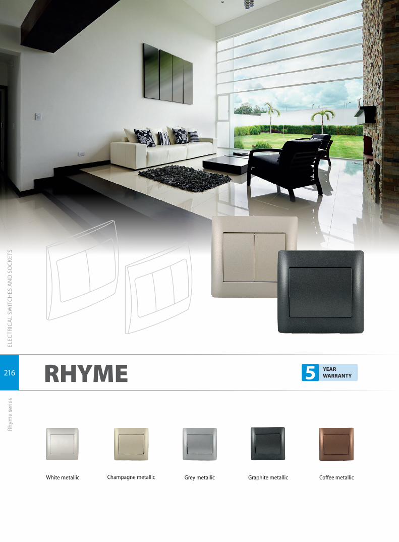
216
ELECTRICAL SWITCHES AND SOCKETSRhyme series
ELEC
TRIC
AL
SWIT
CHES
AN
D S
OCK
ETS
Rhym
e se
ries
White metallic Champagne metallic Grey metallic Graphite metallic Coffee metallic
RHYME 5 YEAR WARRANTY

217
ELECTRICAL SWITCHES AND SOCKETSRhyme series
ELEC
TRIC
AL
SWIT
CHES
AN
D S
OCK
ETS
Rhym
e se
ries
Type Colour Rated cur-rent In (A)
Packing (pcs) Catalogue number
1 button 1 way switch
White metallic
10 10/100
11011
Champagne metallic 11012
Grey metallic 11014
Graphite metallic 11015
Coffee metallic 11016
1 button 2 way switch
White metallic
10 10/100
11021
Champagne metallic 11022
Grey metallic 11024
Graphite metallic 11025
Coffee metallic 11026
1 button cross switch
White metallic
10 10/100
11341
Champagne metallic 11342
Grey metallic 11344
Graphite metallic 11345
Coffee metallic 11346
Type Colour Rated cur-rent In (A)
Packing (pcs) Catalogue number
2 buttons 1 way switch
White metallic
10 10/100
11041
Champagne metallic 11042
Grey metallic 11044
Graphite metallic 11045
Coffee metallic 11046
2 buttons 2 way switch
White metallic
10 10/100
11051
Champagne metallic 11052
Grey metallic 11054
Graphite metallic 11055
Coffee metallic 11056
Type Colour Rated cur-rent In (A)
Packing (pcs) Catalogue number
3 buttons 1 way switch
White metallic
10 10/100
11721
Champagne metallic 11722
Grey metallic 11724
Graphite metallic 11725
Coffee metallic 11726
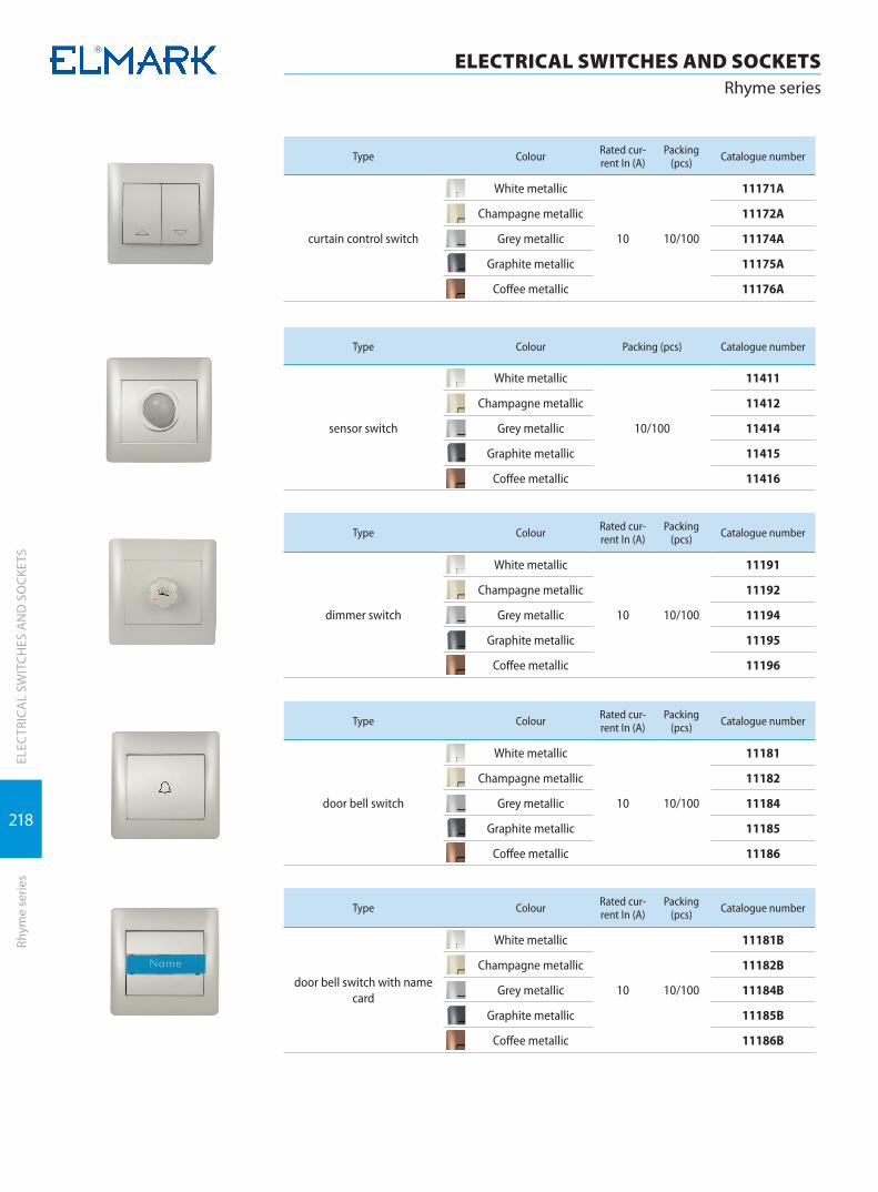
218
ELECTRICAL SWITCHES AND SOCKETSRhyme series
ELEC
TRIC
AL
SWIT
CHES
AN
D S
OCK
ETS
Rhym
e se
ries
Type Colour Rated cur-rent In (A)
Packing (pcs) Catalogue number
curtain control switch
White metallic
10 10/100
11171A
Champagne metallic 11172A
Grey metallic 11174A
Graphite metallic 11175A
Coffee metallic 11176A
Type Colour Packing (pcs) Catalogue number
sensor switch
White metallic
10/100
11411
Champagne metallic 11412
Grey metallic 11414
Graphite metallic 11415
Coffee metallic 11416
Type Colour Rated cur-rent In (A)
Packing (pcs) Catalogue number
dimmer switch
White metallic
10 10/100
11191
Champagne metallic 11192
Grey metallic 11194
Graphite metallic 11195
Coffee metallic 11196
Type Colour Rated cur-rent In (A)
Packing (pcs) Catalogue number
door bell switch
White metallic
10 10/100
11181
Champagne metallic 11182
Grey metallic 11184
Graphite metallic 11185
Coffee metallic 11186
Type Colour Rated cur-rent In (A)
Packing (pcs) Catalogue number
door bell switch with name card
White metallic
10 10/100
11181B
Champagne metallic 11182B
Grey metallic 11184B
Graphite metallic 11185B
Coffee metallic 11186B
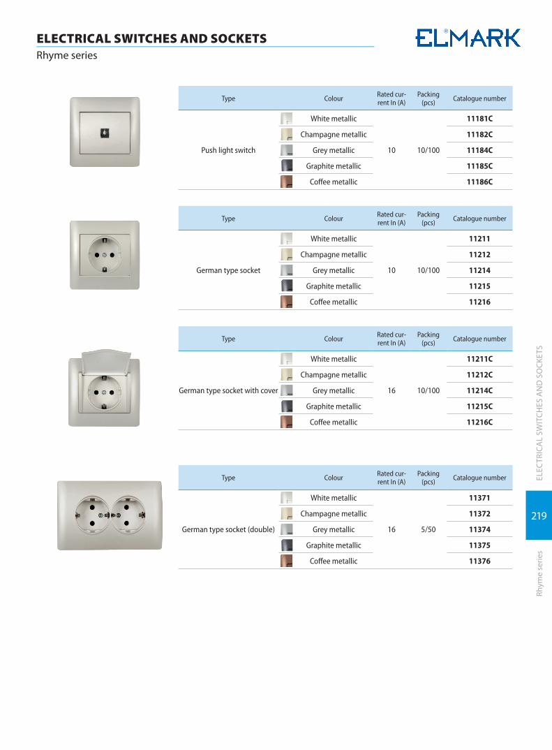
219
ELECTRICAL SWITCHES AND SOCKETSRhyme series
ELEC
TRIC
AL
SWIT
CHES
AN
D S
OCK
ETS
Rhym
e se
ries
Type Colour Rated cur-rent In (A)
Packing (pcs) Catalogue number
Push light switch
White metallic
10 10/100
11181C
Champagne metallic 11182C
Grey metallic 11184C
Graphite metallic 11185C
Coffee metallic 11186C
Type Colour Rated cur-rent In (A)
Packing (pcs) Catalogue number
German type socket
White metallic
10 10/100
11211
Champagne metallic 11212
Grey metallic 11214
Graphite metallic 11215
Coffee metallic 11216
Type Colour Rated cur-rent In (A)
Packing (pcs) Catalogue number
German type socket with cover
White metallic
16 10/100
11211C
Champagne metallic 11212C
Grey metallic 11214C
Graphite metallic 11215C
Coffee metallic 11216C
Type Colour Rated cur-rent In (A)
Packing (pcs) Catalogue number
German type socket (double)
White metallic
16 5/50
11371
Champagne metallic 11372
Grey metallic 11374
Graphite metallic 11375
Coffee metallic 11376
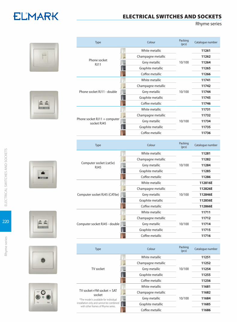
220
ELECTRICAL SWITCHES AND SOCKETSRhyme series
ELEC
TRIC
AL
SWIT
CHES
AN
D S
OCK
ETS
Rhym
e se
ries
Type Colour Packing (pcs) Catalogue number
Phone socketRJ11
White metallic
10/100
11261
Champagne metallic 11262
Grey metallic 11264
Graphite metallic 11265
Coffee metallic 11266
Phone socket RJ11 - double
White metallic
10/100
11741
Champagne metallic 11742
Grey metallic 11744
Graphite metallic 11745
Coffee metallic 11746
Phone socket RJ11 + computer socket RJ45
White metallic
10/100
11731
Champagne metallic 11732
Grey metallic 11734
Graphite metallic 11735
Coffee metallic 11736
Type Colour Packing (pcs) Catalogue number
Computer socket (cat5e)RJ45
White metallic
10/100
11281
Champagne metallic 11282
Grey metallic 11284
Graphite metallic 11285
Coffee metallic 11286
Computer socket RJ45 (CAT6e)
White metallic
10/100
112816E
Champagne metallic 112826E
Grey metallic 112846E
Graphite metallic 112856E
Coffee metallic 112866E
Computer socket RJ45 - double
White metallic
10/100
11711
Champagne metallic 11712
Grey metallic 11714
Graphite metallic 11715
Coffee metallic 11716
Type Colour Packing (pcs) Catalogue number
TV socket
White metallic
10/100
11251
Champagne metallic 11252
Grey metallic 11254
Graphite metallic 11255
Coffee metallic 11256
TV socket+FM socket + SAT socket
*The model is available for individual installation only and cannot be combined
with other frames of Rhyme series.
White metallic
10/100
11681
Champagne metallic 11682
Grey metallic 11684
Graphite metallic 11685
Coffee metallic 11686
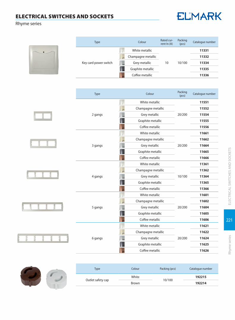
221
ELECTRICAL SWITCHES AND SOCKETSRhyme series
ELEC
TRIC
AL
SWIT
CHES
AN
D S
OCK
ETS
Rhym
e se
ries
Type Colour Rated cur-rent In (A)
Packing (pcs) Catalogue number
Key card power switch
White metallic
10 10/100
11331
Champagne metallic 11332
Grey metallic 11334
Graphite metallic 11335
Coffee metallic 11336
Type Colour Packing (pcs) Catalogue number
2 gangs
White metallic
20/200
11551
Champagne metallic 11552
Grey metallic 11554
Graphite metallic 11555
Coffee metallic 11556
3 gangs
White metallic
20/200
11661
Champagne metallic 11662
Grey metallic 11664
Graphite metallic 11665
Coffee metallic 11666
4 gangs
White metallic
10/100
11361
Champagne metallic 11362
Grey metallic 11364
Graphite metallic 11365
Coffee metallic 11366
5 gangs
White metallic
20/200
11601
Champagne metallic 11602
Grey metallic 11604
Graphite metallic 11605
Coffee metallic 11606
6 gangs
White metallic
20/200
11621
Champagne metallic 11622
Grey metallic 11624
Graphite metallic 11625
Coffee metallic 11626
Type Colour Packing (pcs) Catalogue number
Outlet safety capWhite
10/100192215
Brown 192214
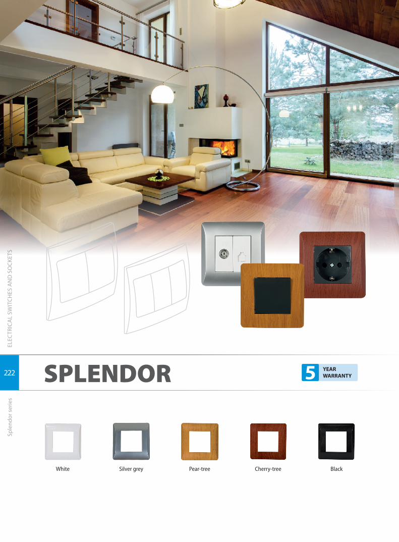
222
ELEC
TRIC
AL
SWIT
CHES
AN
D S
OCK
ETS
ELECTRICAL SWITCHES AND SOCKETSSplendor series
Sple
ndor
ser
ies
SPLENDOR
White Silver grey Pear-tree Cherry-tree Black
5 YEAR WARRANTY

223
ELEC
TRIC
AL
SWIT
CHES
AN
D S
OCK
ETS
Sple
ndor
ser
ies
ELECTRICAL SWITCHES AND SOCKETSSplendor series
Type Colour Packing (pcs) Catalogue number
1 gang White 30/300 06301
1 gang Silver grey 30/300 06302
1 gang Pear-tree 30/300 06305
1 gang Cherry-tree 30/300 06306
1 gang Black 30/300 06303
Type Colour Packing (pcs) Catalogue number
2 gangs White 20/200 06311
2 gangs Silver grey 20/200 06312
2 gangs Pear-tree 20/200 06315
2 gangs Cherry-tree 20/200 06316
2 gangs Black 20/200 06313
Type Colour Packing (pcs) Catalogue number
3 gangs White 15/150 06321
3 gangs Silver grey 15/150 06322
3 gangs Pear-tree 15/150 06325
3 gangs Cherry-tree 15/150 06326
3 gangs Black 15/150 06323
Type Colour Packing (pcs) Catalogue number
single with cover
White
20/200
0629
Silver grey 06292
Pear-tree 06295
Cherry-tree 06296
Black 1629

224
ELEC
TRIC
AL
SWIT
CHES
AN
D S
OCK
ETS
ELECTRICAL SWITCHES AND SOCKETSSplendor series
Sple
ndor
ser
ies
Type Colour Rated current In (A) Packing (pcs) Catalogue number
1 button 1 way switchwhite 10 10/100 0601
dark grey 10 10/100 1601
1 button 2 way switchwhite 10 10/100 0602
dark grey 10 10/100 1602
1 button cross switchwhite 10 10/100 0603
dark grey 10 10/100 1603
Type Colour Rated current In (A) Packing (pcs) Catalogue number
2 buttons 1 way switchwhite 10 10/100 0610
dark grey 10 10/100 1610
2 buttons 1 way switch with light
white 10 10/100 0612
dark grey 10 10/100 1612
2 buttons 2 way switchwhite 10 10/100 0611
dark grey 10 10/100 1611
Type Colour Rated current In (A) Packing (pcs) Catalogue number
German type socketwhite 16 10/100 0616
dark grey 16 10/100 1616
Type Colour Rated current In (A) Packing (pcs) Catalogue number
1 button 1 way switch with light
white 10 10/100 0606
dark grey 10 10/100 1606
1 button 2 way switch with light
white 10 10/100 0607
dark grey 10 10/100 1607
Type Colour Rated current In (A) Packing (pcs) Catalogue number
Push light switchwhite 10 10/100 0605
dark grey 10 10/100 1605
Door bell switch with light
white 10 10/100 0609
dark grey 10 10/100 1609
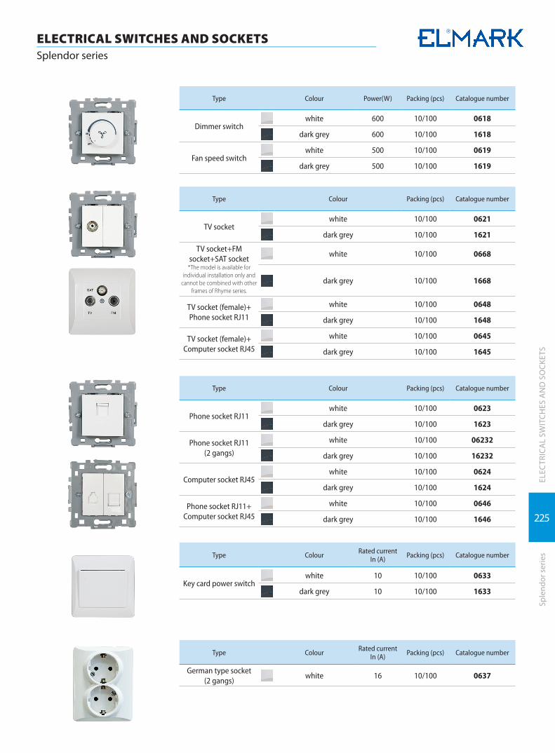
225
ELEC
TRIC
AL
SWIT
CHES
AN
D S
OCK
ETS
Sple
ndor
ser
ies
ELECTRICAL SWITCHES AND SOCKETSSplendor series
Type Colour Power(W) Packing (pcs) Catalogue number
Dimmer switchwhite 600 10/100 0618
dark grey 600 10/100 1618
Fan speed switchwhite 500 10/100 0619
dark grey 500 10/100 1619
Type Colour Packing (pcs) Catalogue number
ТV socketwhite 10/100 0621
dark grey 10/100 1621
TV socket+FM socket+SAT socket
*The model is available for individual installation only and
cannot be combined with other frames of Rhyme series.
white 10/100 0668
dark grey 10/100 1668
TV socket (female)+ Phone socket RJ11
white 10/100 0648
dark grey 10/100 1648
TV socket (female)+ Computer socket RJ45
white 10/100 0645
dark grey 10/100 1645
Type Colour Packing (pcs) Catalogue number
Phone socket RJ11white 10/100 0623
dark grey 10/100 1623
Phone socket RJ11(2 gangs)
white 10/100 06232
dark grey 10/100 16232
Computer socket RJ45white 10/100 0624
dark grey 10/100 1624
Phone socket RJ11+ Computer socket RJ45
white 10/100 0646
dark grey 10/100 1646
Type Colour Rated current In (A) Packing (pcs) Catalogue number
Key card power switchwhite 10 10/100 0633
dark grey 10 10/100 1633
Type Colour Rated current In (A) Packing (pcs) Catalogue number
German type socket(2 gangs)
white 16 10/100 0637
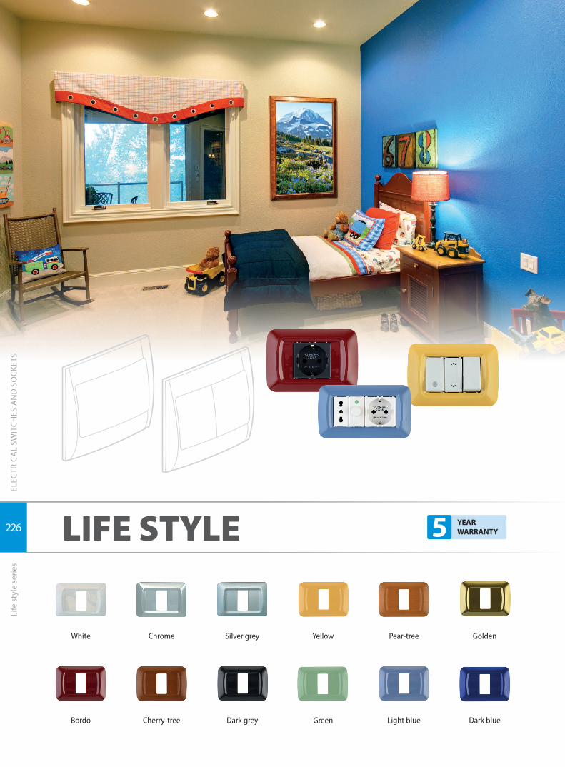
226
ELEC
TRIC
AL
SWIT
CHES
AN
D S
OCK
ETS
ELECTRICAL SWITCHES AND SOCKETSLife style series
Life
sty
le s
erie
s
LIFE STYLE
White Chrome Silver grey Yellow Pear-tree Golden
Bordo Cherry-tree Dark grey Green Light blue Dark blue
5 YEAR WARRANTY
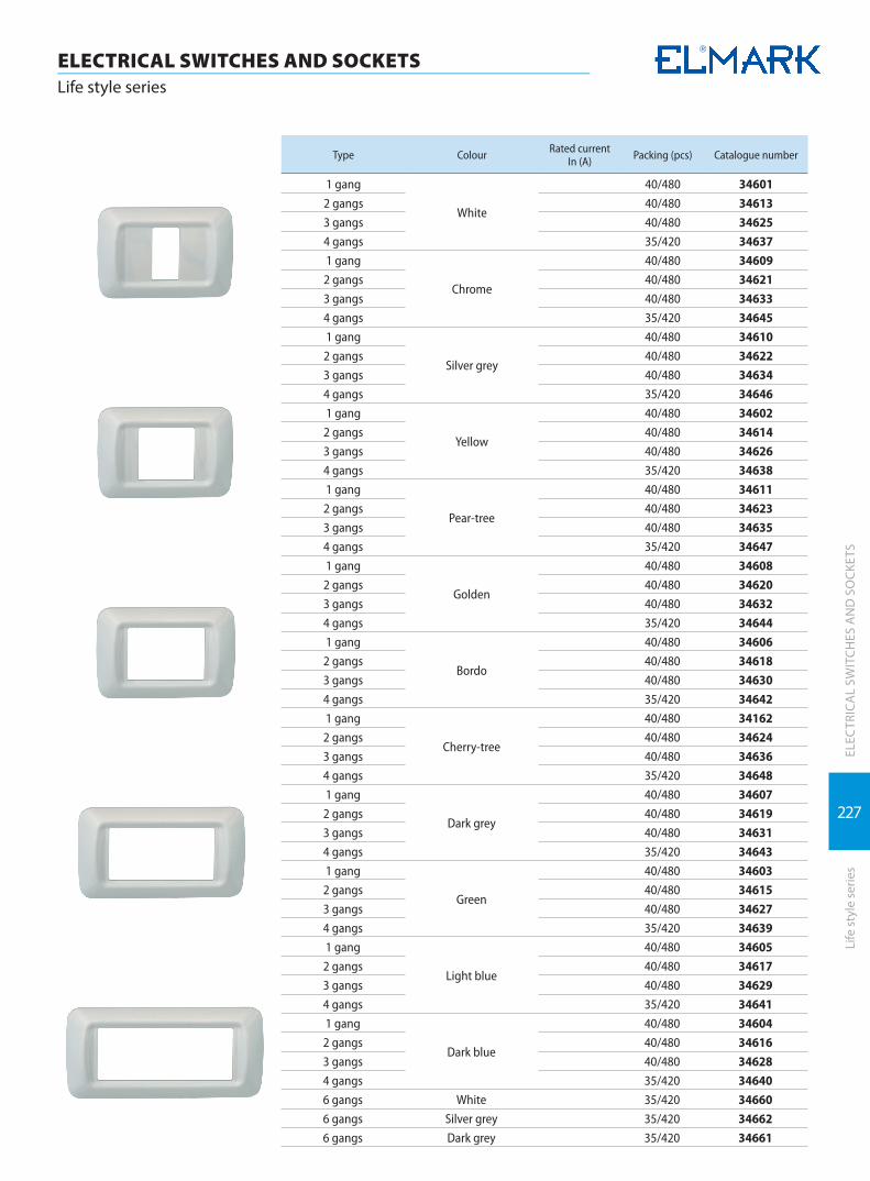
227
ELEC
TRIC
AL
SWIT
CHES
AN
D S
OCK
ETS
Life
sty
le s
erie
s
ELECTRICAL SWITCHES AND SOCKETSLife style series
Type Colour Rated current In (A) Packing (pcs) Catalogue number
1 gang
White
40/480 34601
2 gangs 40/480 34613
3 gangs 40/480 34625
4 gangs 35/420 34637
1 gang
Chrome
40/480 34609
2 gangs 40/480 34621
3 gangs 40/480 34633
4 gangs 35/420 34645
1 gang
Silver grey
40/480 34610
2 gangs 40/480 34622
3 gangs 40/480 34634
4 gangs 35/420 34646
1 gang
Yellow
40/480 34602
2 gangs 40/480 34614
3 gangs 40/480 34626
4 gangs 35/420 34638
1 gang
Pear-tree
40/480 34611
2 gangs 40/480 34623
3 gangs 40/480 34635
4 gangs 35/420 34647
1 gang
Golden
40/480 34608
2 gangs 40/480 34620
3 gangs 40/480 34632
4 gangs 35/420 34644
1 gang
Bordo
40/480 34606
2 gangs 40/480 34618
3 gangs 40/480 34630
4 gangs 35/420 34642
1 gang
Cherry-tree
40/480 34162
2 gangs 40/480 34624
3 gangs 40/480 34636
4 gangs 35/420 34648
1 gang
Dark grey
40/480 34607
2 gangs 40/480 34619
3 gangs 40/480 34631
4 gangs 35/420 34643
1 gang
Green
40/480 34603
2 gangs 40/480 34615
3 gangs 40/480 34627
4 gangs 35/420 34639
1 gang
Light blue
40/480 34605
2 gangs 40/480 34617
3 gangs 40/480 34629
4 gangs 35/420 34641
1 gang
Dark blue
40/480 34604
2 gangs 40/480 34616
3 gangs 40/480 34628
4 gangs 35/420 34640
6 gangs White 35/420 34660
6 gangs Silver grey 35/420 34662
6 gangs Dark grey 35/420 34661
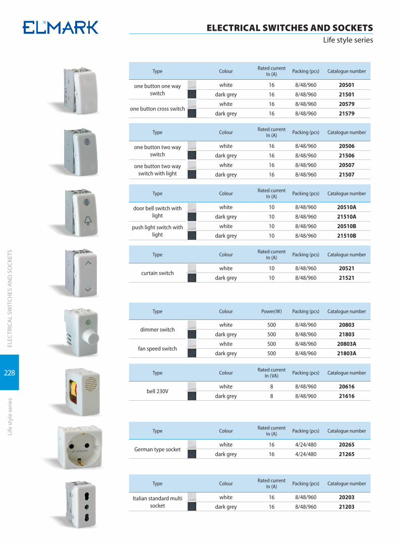
228
ELEC
TRIC
AL
SWIT
CHES
AN
D S
OCK
ETS
ELECTRICAL SWITCHES AND SOCKETSLife style series
Life
sty
le s
erie
s
Type Colour Rated current In (A) Packing (pcs) Catalogue number
one button one way switch
white 16 8/48/960 20501
dark grey 16 8/48/960 21501
one button cross switchwhite 16 8/48/960 20579
dark grey 16 8/48/960 21579
Type Colour Rated current In (A) Packing (pcs) Catalogue number
one button two way switch
white 16 8/48/960 20506
dark grey 16 8/48/960 21506
one button two way switch with light
white 16 8/48/960 20507
dark grey 16 8/48/960 21507
Type Colour Rated current In (A) Packing (pcs) Catalogue number
door bell switch with light
white 10 8/48/960 20510A
dark grey 10 8/48/960 21510A
push light switch with light
white 10 8/48/960 20510B
dark grey 10 8/48/960 21510B
Type Colour Rated current In (A) Packing (pcs) Catalogue number
curtain switchwhite 10 8/48/960 20521
dark grey 10 8/48/960 21521
Type Colour Power(W) Packing (pcs) Catalogue number
dimmer switchwhite 500 8/48/960 20803
dark grey 500 8/48/960 21803
fan speed switchwhite 500 8/48/960 20803A
dark grey 500 8/48/960 21803A
Type Colour Rated current In (VA) Packing (pcs) Catalogue number
bell 230Vwhite 8 8/48/960 20616
dark grey 8 8/48/960 21616
Type Colour Rated current In (A) Packing (pcs) Catalogue number
German type socketwhite 16 4/24/480 20265
dark grey 16 4/24/480 21265
Type Colour Rated current In (A) Packing (pcs) Catalogue number
Italian standard multi socket
white 16 8/48/960 20203
dark grey 16 8/48/960 21203

229
ELEC
TRIC
AL
SWIT
CHES
AN
D S
OCK
ETS
Life
sty
le s
erie
s
ELECTRICAL SWITCHES AND SOCKETSLife style series
Type Colour Packing (pcs) Catalogue number
TV socketwhite 8/48/960 20228
dark grey 8/48/960 21228
Satellite socketwhite 8/48/960 30301
dark grey 8/48/960 31301
Type Colour Packing (pcs) Catalogue number
phone socket RJ 11white 8/48/960 20251
dark grey 8/48/960 21251
computer socket RJ 45white 8/48/960 20266
dark grey 8/48/960 21266
Type Colour Packing (pcs) Catalogue number
decorative coverwhite 8/48/960 20056
dark grey 8/48/960 21056
Type Packing (pcs) Catalogue number
Surface mounting box - for LIFE STYLE series
double 5 / 250 2702
triple 5 / 200 2703
Type IP code Packing (pcs) Catalogue number
Watertight box - for LIFE STYLE series
triple 44 1 / 100 22451А
quadruple 44 1 / 100 22461А
Type Packing (pcs) Catalogue number
Frame - for LIFE STYLE series
double frame 10 / 400 24262
triple frame 10 / 400 24201
quadruple frame 10 / 400 24202
sixfold frame 10 / 200 24206LF* Single switch or socket use triple frame
Type Packing (pcs) Catalogue number
Console box for brick and con-crete - for LIFE STYLE series
triple 10 / 300 24203
quadruple 10 / 200 71304
sixfold 10 / 200 68206* Single, double and triple switch or socket use triple console
Type Packing (pcs) Catalogue number
Console box for plasterboardtriple 160 24205
quadruple 150 24206* Single, double and triple switch or socket use triple console

230
ELEC
TRIC
AL
SWIT
CHES
AN
D S
OCK
ETS
ELECTRICAL SWITCHES AND SOCKETSBasic series
Basi
c se
ries
BASIC
White Cream Silver grey Pear tree
5 YEAR WARRANTY

231
ELEC
TRIC
AL
SWIT
CHES
AN
D S
OCK
ETS
Basi
c se
ries
ELECTRICAL SWITCHES AND SOCKETSBasic series
Type Colour Rated current In (A) Packing (pcs) Catalogue number
1 button 1 way switch
White 10 10/100 38000
Cream 10 10/100 38001
Silver grey 10 10/100 38002
Pear tree 10 10/100 38005
1 button 2 way switch
White 10 10/100 38010
Cream 10 10/100 38011
Silver grey 10 10/100 38012
Pear tree 10 10/100 38015
Type Colour Rated current In (A) Packing (pcs) Catalogue number
1 button 1 way switch with light
White 10 10/100 38700
Cream 10 10/100 38701
Silver grey 10 10/100 38702
Pear tree 10 10/100 38705
Type Colour Rated current In (A) Packing (pcs) Catalogue number
Cross switch
White 10 10/100 38070
Cream 10 10/100 38071
Silver grey 10 10/100 38072
Pear tree 10 10/100 38075
Type Colour Rated current In (A) Packing (pcs) Catalogue number
2 buttons 1 way switch
White 10 10/100 38050
Cream 10 10/100 38051
Silver grey 10 10/100 38052
Pear tree 10 10/100 38055
Type Colour Power(W) Packing (pcs) Catalogue number
Dimmer switch
White 400 10/100 38800
Cream 400 10/100 38801
Silver grey 400 10/100 38802
Pear tree 400 10/100 38805

232
ELEC
TRIC
AL
SWIT
CHES
AN
D S
OCK
ETS
ELECTRICAL SWITCHES AND SOCKETSBasic series
Basi
c se
ries
Type Colour Rated current In (A) Packing (pcs) Catalogue number
Push light switch
White 10 10/100 38100
Cream 10 10/100 38101
Silver grey 10 10/100 38102
Pear tree 10 10/100 38105
Type Colour Rated current In (A) Packing (pcs) Catalogue number
Door bell switch
White 10 10/100 38120
Cream 10 10/100 38121
Silver grey 10 10/100 38122
Pear tree 10 10/100 38125
Type Colour Rated current In (A) Packing (pcs) Catalogue number
German type socket
White 16 10/100 38200
Cream 16 10/100 38201
Silver grey 16 10/100 38202
Pear tree 16 10/100 38205
Type Colour Rated current In (A) Packing (pcs) Catalogue number
German type socket with cover
White 16 10/100 38250
Cream 16 10/100 38251
Silver grey 16 10/100 38252
Pear tree 16 10/100 38255
Type Colour Packing (pcs) Catalogue number
Phone socket
White 10/100 38350
Cream 10/100 38351
Silver grey 10/100 38352
Pear tree 10/100 38355
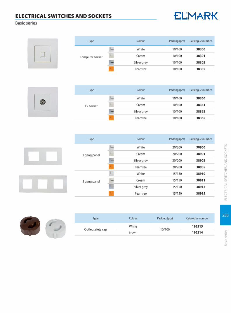
233
ELEC
TRIC
AL
SWIT
CHES
AN
D S
OCK
ETS
Basi
c se
ries
ELECTRICAL SWITCHES AND SOCKETSBasic series
Type Colour Packing (pcs) Catalogue number
Computer socket
White 10/100 38300
Cream 10/100 38301
Silver grey 10/100 38302
Pear tree 10/100 38305
Type Colour Packing (pcs) Catalogue number
TV socket
White 10/100 38360
Cream 10/100 38361
Silver grey 10/100 38362
Pear tree 10/100 38365
Type Colour Packing (pcs) Catalogue number
2 gang panel
White 20/200 38900
Cream 20/200 38901
Silver grey 20/200 38902
Pear tree 20/200 38905
3 gang panel
White 15/150 38910
Cream 15/150 38911
Silver grey 15/150 38912
Pear tree 15/150 38915
Type Colour Packing (pcs) Catalogue number
Outlet safety capWhite
10/100192215
Brown 192214
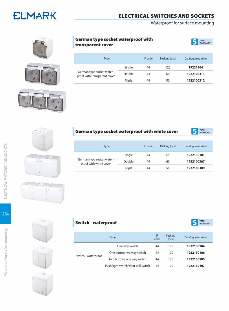
234
ELEC
TRIC
AL
SWIT
CHES
AN
D S
OCK
ETS
ELECTRICAL SWITCHES AND SOCKETSWaterproof for surface mounting
Wat
erpr
oof f
or s
urfa
ce m
ount
ing
German type socket waterproof with transparent cover 5 YEAR
WARRANTY
Type IP code Packing (pcs) Catalogue number
German type socket water-proof with transparent cover
Single 44 120 19221304
Double 44 60 1922100311
Triple 44 50 1922100312
German type socket waterproof with white cover 5 YEAR WARRANTY
Type IP code Packing (pcs) Catalogue number
German type socket water-proof with white cover
Single 44 120 1922130101
Double 44 60 1922100307
Triple 44 50 1922100309
Switch - waterproof 5 YEAR WARRANTY
Type IP code
Packing (pcs) Catalogue number
Switch - waterproof
One way switch 44 120 1922130104
One button two way switch 44 120 1922130106
Two buttons one way switch 44 120 1922130105
Push light switch/door bell switch 44 120 1922130107
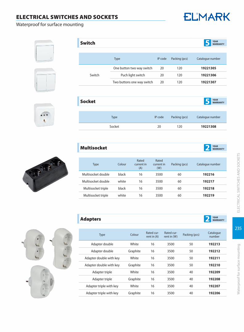
235
ELEC
TRIC
AL
SWIT
CHES
AN
D S
OCK
ETS
Wat
erpr
oof f
or s
urfa
ce m
ount
ing
ELECTRICAL SWITCHES AND SOCKETSWaterproof for surface mounting
Switch 5 YEAR WARRANTY
Type IP code Packing (pcs) Catalogue number
Switch
One button two way switch 20 120 19221305
Puch light switch 20 120 19221306
Two buttons one way switch 20 120 19221307
Socket 5 YEAR WARRANTY
Type IP code Packing (pcs) Catalogue number
Socket 20 120 19221308
Multisocket 2 YEAR WARRANTY
Type ColourRated
current in (A)
Rated current in
(W)Packing (pcs) Catalogue number
Multisocket double black 16 3500 60 192216
Multisocket double white 16 3500 60 192217
Multisocket triple black 16 3500 60 192218
Multisocket triple white 16 3500 60 192219
Adapters 2 YEAR WARRANTY
Type Colour Rated cur-rent in (A)
Rated cur-rent in (W) Packing (pcs) Catalogue
number
Adapter double White 16 3500 50 192213
Adapter double Graphite 16 3500 50 192212
Adapter double with key White 16 3500 50 192211
Adapter double with key Graphite 16 3500 50 192210
Adapter triple White 16 3500 40 192209
Adapter triple Graphite 16 3500 40 192208
Adapter triple with key White 16 3500 40 192207
Adapter triple with key Graphite 16 3500 40 192206

236
ELEC
TRIC
AL
SWIT
CHES
AN
D S
OCK
ETS
ELECTRICAL SWITCHES AND SOCKETSPlugs
Plug
s
Rubber- coated socket 2 YEAR WARRANTY
Type Colour IP code Packing (pcs) Catalogue number
Rubber- coated socket black 44 25 / 100 192220
Rubber-coated plug 2 YEAR WARRANTY
Type Colour IP code Packing (pcs) Catalogue number
Rubber- coated plug black 44 25 / 100 192221
Plug with PVC muff 2 YEAR WARRANTY
Type Rated current In (A) Colour Material Packing (pcs) Catalogue number
Plug 16 black / white with pvc muff 300 192113
Plug bakelite 2 YEAR WARRANTY
Type Rated current In (A) Colour Material Packing (pcs) Catalogue number
Plug 16 white bakelite 80 19211102
Plug 16 black bakelite 80 19211101