catalogue hy11-2500/uk chapter 3: contents proportional dc ...cairohydraulic.com/products/1- parker...
TRANSCRIPT

3-1
Catalogue HY11-2500/UK
3
Chapter 3:Proportional DC ValvesContents
D1FT Standard performance • 3- 3
D*1FW • • • 3- 9
D*1FT • • • •
WL*06* Standard performance, • optional 3-19
high repeatability
WL*10* Standard performance, • optional 3-27
high repeatability
D*1FS High performance • • • • • 3-33
D1FX • • • 3-41
D1FH Servo performance • • • 3-47
D*1FH • • • • • • 3-53
Accessories 3-63
Mounting patterns 3-64
Series Description Direct Pilot Spool Integrated Pageoperated operated feedback electronics
Size NG 06 10 10 16 25 32Size ISO/CETOP 3 5 5 7 8 10
If you are interested in fast delivery, please fol-low this hint in our ordering codes when choos-ing your individual product:

3-2
Catalogue HY11-2500/UK
3
Notes

3-3
D1FT.PM6.5 RH
Direct Operated Proportional DC ValveSeries D1FT
Catalogue HY11-2500/UK
3
Characteristics
The D1FT directional control valve of the nominal sizeNG6 (CETOP 3) is a proportional valve providing vari-able flow rates.This valve is used with integrated control electronics. Typi-cal applications are: soft switching via adjustable rampsfor the reduction of hydraulic and mechanical shocks,electrically adjustable flow rates / speeds for automatingmachine functions.
Technical features• Integrated control electronics with ramp adjustment
• Low leakage
• Progressive flow characteristics for sensitive adjust-ment of flow rate
• Spring centred spool
• Manual override

3-4
D1FT.PM6.5 RH
Direct Operated Proportional DC ValveSeries D1FT
Catalogue HY11-2500/UK
3
Ordering Code
D F T
DCvalve
DC valve(with integr.electronics)
Nominalsize
NG06 /CETOP 3
Spooltype
0
Designseries
Style SealNBR
(different sealcompound by
request)
Electronicdesign
Valveaccessories
0
Electronicaccessories
Code
F
G
Voltage
Voltage input 0...±10Vwith reference output
+10V / -10V
Current input 0...±20mA
Flowcontrol
StyleCode
C
E
K
Code
E01CE01FE01H
Spool type
Please order plug/s separately.See chapter 3 accessories.
Flow [l/min]at ∆p 5bar
per metering edge
7.51520
N1
E02CE02FE02H
15 / 7.5
7.51520
B31F
15 / 7.5B32F
QB = QA /2
QB = QA /2

3-5
D1FT.PM6.5 RH
Direct Operated Proportional DC ValveSeries D1FT
Catalogue HY11-2500/UK
3
General
Design Direct operated proportional DC valve with integrated power amplifier
Actuation Proportional solenoid
Mounting position Optional
Environmental temperature [°C] -20 ... +60
Hydraulics
Pressure medium Hydraulic oil as per DIN 51 524 ... 535, other fluids by request
Viscosity, recommended [mm²/s] 30 ... 80max. admiss. [mm²/s] 20 ... 380
Oil temperature [°C] 0 ... 60
Filtration Permissible contamination class to achieve with filterof pressure medium as per NAS 1638 β x = 75
Main stage class 9 X = 15
Mounting pattern DIN 24340 / ISO 4401 / CETOP RP121 / NFPA
Operating pressure [bar] Port P, A, B, max. 350 bar, Port T max. 50 bar
Nominal size DIN NG06
CETOP 03
Type C F H
Weight [kg] 2.5 2.5 2.5
Nominal flow at ∆p=5barper metering edge [l/min] 7.5 15 20
Static / Dynamic
Hysteresis [%] < 8
Sensitivity [%] < 2
Response time t [ms] 100
Integrated electronics (D*FT)
Supply voltage [V] 14.5 ... 30
Power consumption [VA] 22
Current consumption max. [A] 2.8
Input signalPolarity D against E positive corresponds P-A, B-T, negative corresponds P-B, A-TVoltage [V] ±10Impedance [kOhm] 100
Current [mA] ±20Impedance [Ohm] 500
Reference output(10mA max.) [V] +10 (Pin C) / -10 (Pin F)
Ramp time [s] 0...3
Plug connector 6 + PE DIN 43563
Technical Data

3-6
D1FT.PM6.5 RH
Direct Operated Proportional DC ValveSeries D1FT
Catalogue HY11-2500/UK
3
Electronics
Block diagram
Arrangement of the potentiometers

3-7
D1FT.PM6.5 RH
Direct Operated Proportional DC ValveSeries D1FT
Catalogue HY11-2500/UK
3
Characteristic Curves
Flow characteristics
Spool Code E*
at ∆p 5bar per metering edge
Operating limits100% command signal
Spool Code B*

3-8
D1FT.PM6.5 RH
Direct Operated Proportional DC ValveSeries D1FT
Catalogue HY11-2500/UK
3
Dimensions
NBR
BK375 4x M5x30 8.1 Nm SK-D1FT-N30DIN 912 12.9
Surface finish

3-9
D_1FW-D_1FT.PM6.5 RH
Pilot Operated Proportional DC ValveSeries D*1FW / D*1FT
Catalogue HY11-2500/UK
3
Characteristics
The D*1FW / D*1FT pilot-operated proportional DCvalves are available in NG10 (CETOP5), NG16(CETOP7) and NG25 (CETOP8).
These valves (D*1FW) are controlled electrically with theexternal power amplifiers PWD00A-400 or used as valveswith integrated electronics (D*1FT).
Typical applications include reproducible control of ac-tuator speed in rapid / slow speed profiling, and smoothacceleration and deceleration performance.
Technical features• Low leakage
• Progressive flow characteristics for sensitive adjust-ment of flow rate
• Fail safe centre position
• Optional: centre position monitoring
• D*1FT version with integrated power amplifier withramp adjustment
D31FW
D31FW

3-10
D_1FW-D_1FT.PM6.5 RH
Pilot Operated Proportional DC ValveSeries D*1FW / D*1FT
Catalogue HY11-2500/UK
3
D31 D41 D91
75 - -
- 200 -
- - 400
Ordering Code
Code Inlet Drain
1 internal external
2 external external
4 internal internal
5 external internal
D F
DCvalve
Spooltype
Flow
Code
L
X
Solenoid
6 VDC
16 VDC
1
Nominalsize
W
Valveaccessories
SolenoidPilotconnection
C
Nominal size
NG10 / CETOP 5
NG16 / CETOP 7
NG25 / CETOP 8
Code
3
4
91)
Designseries
Flowcontrol
SealNBR
(differentseal
compoundby request)
N W
Please order plug/s separately.See chapter 3 accessories.
Flow [l/min]at ∆p = 5bar per metering edgeCode
C
F
H
Code
Standard
Monitor switch(plug included)
0
8
Valve accessories
Code
E01
E02
B31
B32
Spool type
QB = QA /2
QB = QA /2
1) with enlarged connections Ø32mm

3-11
D_1FW-D_1FT.PM6.5 RH
Pilot Operated Proportional DC ValveSeries D*1FW / D*1FT
Catalogue HY11-2500/UK
3
Ordering Code
Code Inlet Drain
1 internal external
2 external external
4 internal internal
5 external internal
D F
DCvalve
Spooltype
Flow
1
Nominalsize
T
Valveaccessories
Code
Voltage input0...±10V, with
reference output+10V/-10V
Current input0...±20mA
F
G
Electronicvariation
Pilotconnection
C
Designseries
Electronicaccessories
0
Electronicvariation
Flowcontrol
Integratedelectronics
SealNBR
(different sealcompound by
request)
Please order plug/s separately.See chapter 3 accessories.
N
D31 D41 D91
75 - -
- 200 -
- - 400
Nominal size
NG10 / CETOP 5
NG16 / CETOP 7
NG25 / CETOP 8
Code
3
4
91)
Flow [l/min]at ∆p = 5bar per metering edgeCode
C
F
H
Code
Standard
Monitor switch(plug included)
0
8
Valve accessories
Code
E01
E02
B31
B32
Spool type
QB = QA /2
QB = QA /2
1) with enlarged connections Ø32mm

3-12
D_1FW-D_1FT.PM6.5 RH
Pilot Operated Proportional DC ValveSeries D*1FW / D*1FT
Catalogue HY11-2500/UK
3
Technical Data
General
Design Pilot-operated DC Valve with integrated power amplifier
Actuation Proportional solenoid
Mounting position optional
Environmental temp. [°C] -20...60
Hydraulics
Pressure medium Hydraulic oil as per DIN 51 524 ... 535, other fluids by request
Viscosiy, recommended [mm²/s] 30 ... 80max. admiss. [mm²/s] 20 ... 380
Pressure fluid temperature [°C] 0 ... 60
Filtration Permissible contamination class of to achieve with filterpressure medium as per NAS 1638 ... β x = 75
Pilot stage Class 7 X = 5Main stage Class 9 X = 15
Mounting pattern DIN 24340 / ISO 4401 / CETOP RP121 / NFPA
Operating pressure [bar] Port P, T, A, B, X max. 350 bar, port Y max. 10 bar
Nominal size DIN NG10 NG16 NG25
CETOP 05 07 08
Weight [kg] 7.1 10.8 19
Nominal flow at ∆p=5 barper metering edge [l/min] 75 200 400
Drain (140bar) [l/min] 0.1 0.2 0.6
Pilot stage
Pilot pressure [bar] 20 - 350 (optimal dynamics at 50)
Pilot volume req. (constant) [l/min] < 1.2
Static / Dynamic
Hysteresis [%] < 5
Repeatability [%] < 1
Response time [ms] 60 75 100
Solenoid
Type Code L
Protection class, DIN 40050 IP 54
Nominal resistance [Ohm] 2.2
Nominal current (100%ED) [A] 2.5
Voltage [V] 6
Electrical connection EN 175301-803
Integrated electronics (D*1FT)
Supply voltage [V] 14.5 ... 30
Power consumption [VA] 22
Input signal
Polarity * D against E positive corresponds to P-B, A-T, negative corresponds to P-A, B-TVoltage [V] ±10Impedance [kOhm] 100Current [mA] ±20Impedance [Ohm] 500
Reference output(10mA max.) [V] +10 / -10
Ramp time [s] 0...3
Plug 6 + PE DIN 43563
* inverse polarity by request

3-13
D_1FW-D_1FT.PM6.5 RH
Pilot Operated Proportional DC ValveSeries D*1FW / D*1FT
Catalogue HY11-2500/UK
3
Electronics
Block diagram
Arrangement of the potentiometers

3-14
D_1FW-D_1FT.PM6.5 RH
Pilot Operated Proportional DC ValveSeries D*1FW / D*1FT
Catalogue HY11-2500/UK
3
Flow characteristicsat ∆p = 5bar per metering edge
Characteristic Curves
D*1FWSpool code E* Spool code B*
D*1FTSpool code E* Spool code B*

3-15
D_1FW-D_1FT.PM6.5 RH
Pilot Operated Proportional DC ValveSeries D*1FW / D*1FT
Catalogue HY11-2500/UK
3
Dimensions
Pilot connection
D31F*
D41F*
D91F*

3-16
D_1FW-D_1FT.PM6.5 RH
Pilot Operated Proportional DC ValveSeries D*1FW / D*1FT
Catalogue HY11-2500/UK
3
D41FW
D31FW
NBR
BK385 4x M6x40 13.6 Nm SK-D31FW-N20DIN 912 12.9
Surface finish
NBR
2x M6x55 13.6 NmBK320 4x M10x60 65 Nm SK-D41FW-N20
DIN 912 12.9
Surface finish
Dimensions

3-17
D_1FW-D_1FT.PM6.5 RH
Pilot Operated Proportional DC ValveSeries D*1FW / D*1FT
Catalogue HY11-2500/UK
3
Dimensions
D31FT
D91FW
NBR
BK385 4x M6x40 13.6 Nm SK-D31FT-N30DIN 912 12.9
Surface finish
NBR
BK360 6 x M12x95 115 Nm SK-D91FW-N20DIN 912 12.9
Surface finish

3-18
D_1FW-D_1FT.PM6.5 RH
Pilot Operated Proportional DC ValveSeries D*1FW / D*1FT
Catalogue HY11-2500/UK
3
D91FT
NBR
BK360 6 x M12x95 115 Nm SK-D91FT-N20DIN 912 12.9
Surface finish
D41FT
NBR
2x M6x55 13.6 NmBK320 4x M10x60 65 Nm SK-D41FT-N30
DIN 912 12.9
Surface finish
Dimensions

3-19
WL_ 06.PM6.5 RH
Direct Operated Proportional DC ValveSeries WL*06*
Catalogue HY11-2500/UK
3
Characteristics
The WLL directional control valve series of the nominalsize NG6 (CETOP3) provides variable flow rates.
These valves are available with/without spool positionfeedback and electrically controlled by the external dig-ital amplifier modules VRD350/355 or PWD00A-400.
Typical applications are:Exact and repeatible adjustment of flow rates, applica-tions with rapid / slow speed profiles and the positioningof hydraulic drives.
Technical features• Spool / sleeve design
• High reproducibility from valve to valve
• Low hysteresis
• Progressive flow characteristics for sensitive adjust-ment of flow rate
• Manual override
• Spool position feedback, optional

3-20
WL_ 06.PM6.5 RH
Direct Operated Proportional DC ValveSeries WL*06*
Catalogue HY11-2500/UK
3
Ordering Code
W F
DCvalve
Spooltype
Designseries
Code
G09
Voltage
9 VDC
Solenoidvoltage(different
voltage byrequest)
Seriesletter
L
Style
Spoolpositionfeedback
CodeSpool position
feedback
without feedback
with feedback(plug included)
K
R
Code Style
L43
F42
3 G09
Please order plug/s separately.See chapter 3 accessories.
Code
G06P003G06P006G06P012G06P020
Spool type
Flow [l/min]at ∆p 5bar
per meteringedge
36
1220
K06P020 20
G06A006G06A012G06A020
6 / 312 / 6
20 / 10
K06A020 20 / 10
QB = QA /2
QB = QA /2

3-21
WL_ 06.PM6.5 RH
Direct Operated Proportional DC ValveSeries WL*06*
Catalogue HY11-2500/UK
3
Technical Data
General
Design Direct operated proportional DC valve
Actuation Proportional solenoid
Mounting position Optional
Environmental temperature [°C] -20 ... +60
Hydraulics
Pressure fluid Hydraulic oil as per DIN 51 524 ... 535, other fluids by request
Viscosity, recommended [mm²/s] 30 ... 80max. admiss. [mm²/s] 20 ... 380
Pressure fluid temperature [°C] 0 ... +60
Filtration Permitted contamination class of to achieve with filterpressure medium as per NAS 1638 β x = 75class 7 - 9 X = 10
Mounting pattern DIN 24340 / ISO 4401 / CETOP RP121 / NFPA
Operating pressure [bar] Port P, A, B, max. 315 bar, Port T max. 210 bar
Nominal size DIN NG06
CETOP 03
Weight [kg] 2.2 (2.5 with LVDT)
Nominal flow at ∆p=5 barper metering edge [l/min] 3, 6, 12 and 20
Drain [l/min] see curves
Static / Dynamic Code "K" without spool position feedback Code "R" with spool position feedback
Hysteresis [%] ≤ 4 ≤ 0.3
Threshold [%] 0.5 0.2
Sensitivity [%] ≤ 0.3 ≤ 0.1
Response time t at 100% [ms] ≤ 30 ≤ 20
Solenoid
Type G09
Protection class DIN 40050 IP 65
Power consumption [VA] 17
Nominal resistance [Ohm] 2.2
Nominal current (100%ED) [A] 2.7
Voltage [V] 9
Electrical connection, solenoid EN 175301-803
Elec. connection, pos. indicator M12 / 4pin
EMV conformity, pos. indicator EN 50081-2
EN 50082-1
NoteStandard seal compound is NBR.
WiringSolenoid coil Feedback
1 = coil connection2 = coil connectionPE = ground potential
1 = output, actual spool position2 = supply (+24V)3 = GND (0V)4 = not used

3-22
WL_ 06.PM6.5 RH
Direct Operated Proportional DC ValveSeries WL*06*
Catalogue HY11-2500/UK
3
Flow characteristicsat ∆p = 5bar per metering edge
Dynamic response (WLL43G06* with power amplifier VRD350)measured at: ±25% amplitude, offset 50%
Spool code G06P* / K06P*
Spool code G06A* / K06A*
Characteristic Curves

3-23
WL_ 06.PM6.5 RH
Direct Operated Proportional DC ValveSeries WL*06*
Catalogue HY11-2500/UK
3
Characteristic Curves
Operation limits Q = f (∆∆∆∆∆p)
WL*P006*K
WL*P020*K
WL*P012*K
WL*P003*K

3-24
WL_ 06.PM6.5 RH
Direct Operated Proportional DC ValveSeries WL*06*
Catalogue HY11-2500/UK
3
Characteristic Curves
Step response
Code "K" without spool position feedback
Code "R" with spool position feedback

3-25
WL_ 06.PM6.5 RH
Direct Operated Proportional DC ValveSeries WL*06*
Catalogue HY11-2500/UK
3
Dimensions
WLF42*
WLL43*
NBR
BK375 4x M5x30 8.1 Nm SK-WLL06FDIN 912 12.9
Surface finish

3-26
WL_ 06.PM6.5 RH
Direct Operated Proportional DC ValveSeries WL*06*
Catalogue HY11-2500/UK
3
Notes

3-27
WL_10.PM6.5 RH
Direct Operated Proportional DC ValveSeries WL*10*
Catalogue HY11-2500/UK
3
Characteristics
The WLL directional control valve series of the nominalsize NG10 (CETOP 5) provides variable flow rates.
These valves are available with/without spool positionfeedback and electrically controlled by the external dig-ital amplifier modules VRD350/355 or PWD00A-400.
Typical applications are:Exact and repeatible adjustment of flow rates, applica-tions with rapid / slow speed profile and the positioningof hydraulic drives.
Technical features• Spool / sleeve design
• High reproducibility from valve to valve
• Low hysteresis
• Progressive flow characteristics for sensitive adjust-ment of flow rate
• Manual override
• Spool position feedback, optional

3-28
WL_10.PM6.5 RH
Direct Operated Proportional DC ValveSeries WL*10*
Catalogue HY11-2500/UK
3
Ordering Code
W
DCvalve
Spooltype
L
Design Designseries
E
SealNBR
(differentseal
compoundby request)
Please order plug/s separately.See accessories.
Code Style
L43
F42
Code
G10P040G10P060
Spool type
Flow [l/min]at ∆p 5bar
per meteringedge
4060
K10P060 60
G10A060 60 / 30
K10A060 60 / 30
QB = QA /2
QB = QA /2
CodeSpool position
feedback
without feedback
with feedback(plug included)
K
R

3-29
WL_10.PM6.5 RH
Direct Operated Proportional DC ValveSeries WL*10*
Catalogue HY11-2500/UK
3
Technical Data
General
Design Direct operated proportional DC valve
Actuation Proportional solenoid
Mounting position Optional
Environmental temp. [°C] -20 ... +60
Hydraulics
Pressure medium Hydraulic oil as per DIN 51 524 ... 535, other fluids by request
Viscosity, recommended [mm²/s] 30 ... 80max. admiss. [mm²/s] 20 ... 380
Oil temperature [°C] 0 ... 60
Filtration Permitted contamination class of to achieve with filterpressure medium as per NAS 1638 β x = 75class 7 - 9 X = 10
Mounting pattern DIN 24340 / ISO 4401 / CETOP RP121 / NFPA
Operating pressure [bar] Port P, A, B, max. 315 bar, Port T max. 210 bar
Nominal size DIN NG10
CETOP 05
Weight [kg] 6.5
Nominal flow at ∆p=5 barper metering edge [l/min] 40 and 60
Static / Dynamic Code K" without spool position feedback Code "R" with spool position feedback
Hysteresis [%] ≤ 6 ≤ 0.3
Threshold [%] 0.8 0.3
Sensitivity [%] ≤ 0.4 ≤ 0.2
Response time t for 100% [ms] ≤ 40 ≤ 33
Solenoid
Type G09
Protection class DIN 40050 IP 65
Power consumption [VA] 31.5
Nominal resistance [Ohm] 1.8
Nominal current (100%ED) [A] 3.4
Voltage [V] 9
Electrical connection solenoid EN 175301-803
WiringSolenoid coil
1 = coil connection2 = coil connectionPE = ground potential

3-30
WL_10.PM6.5 RH
Direct Operated Proportional DC ValveSeries WL*10*
Catalogue HY11-2500/UK
3
Characteristic Curves
Dynamic response (WLL43G10* with power amplifier VRD350)measured at: ±25% amplitude, offset 50%
Flow characteristicsat ∆p = 5bar per metering edge
Spool code G06P* / K06P*
Spool code G06A* / K06A*

3-31
WL_10.PM6.5 RH
Direct Operated Proportional DC ValveSeries WL*10*
Catalogue HY11-2500/UK
3
Characteristic Curves
Operation limits Q = f (∆∆∆∆∆p)
WL*P060*
Step response
Code "K" without spool position feedback
WL*P040*
Code "R" with spool position feedback

3-32
WL_10.PM6.5 RH
Direct Operated Proportional DC ValveSeries WL*10*
Catalogue HY11-2500/UK
3
Dimensions
WLF42*
WLL43*
NBR
BK385 4x M6x40 13.6 Nm SK-WLL10FEDIN 912 12.9
Surface finish

3-33
D_1FS.PM6.5 RH
Pilot Operated Proportional DC ValveSeries D*1FS
Catalogue HY11-2500/UK
3
Characteristics
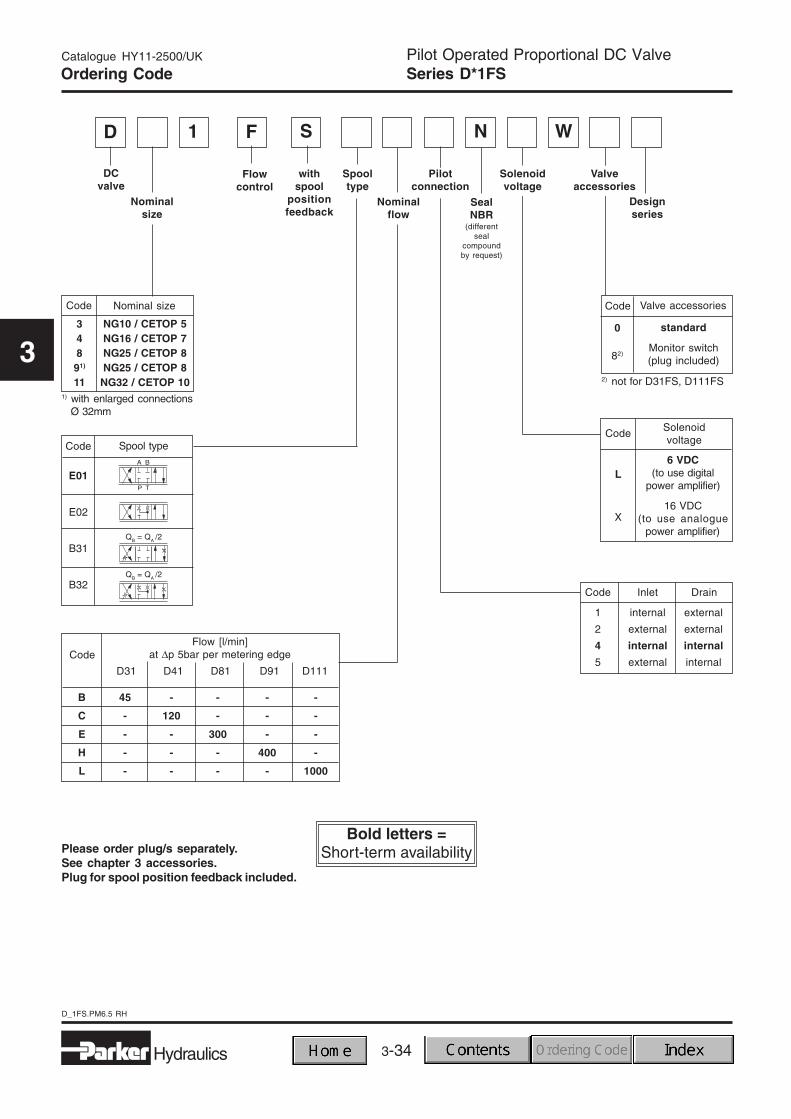
The D*1FS pilot operated proportional valves series ofthe nominal sizes NG10 to NG32 (CETOP 5 to 10) pro-vides flow rate control.
These valves are electrically controlled with EW* seriesanalogue power amplifiers or with VRD350/355 digitalpower amplifiers. The spool position is controlled by anelectronic feedback device.
Typical applications are:Exact and reproducible adjustment of flow rates, move-ment of the drive in rapid / slow speed profile and the softacceleration and deceleration to improve the drive char-acteristics.
Technical features• Low leakage
• Sensitive flow rate adjustment
• Spool position feedback
• Fail safe centre position
• Optional: center position monitoring
• Expanded functions with digital amplifier VRD350
3-34
D_1FS.PM6.5 RH
Pilot Operated Proportional DC ValveSeries D*1FS
Catalogue HY11-2500/UK
3
Code Inlet Drain
1 internal external
2 external external
4 internal internal
5 external internal
Ordering Code
D F
DCvalve
Spooltype
Nominalflow
Code
L
X
Solenoidvoltage
6 VDC(to use digital
power amplifier)
16 VDC(to use analogue
power amplifier)
Code
standard
Monitor switch(plug included)
0
82)
Valve accessoriesNominal size
NG10 / CETOP 5NG16 / CETOP 7NG25 / CETOP 8NG25 / CETOP 8
NG32 / CETOP 10
1
Nominalsize
Code
34891)
111) with enlarged connections
Ø 32mm
S
Valveaccessories
Solenoidvoltage
Pilotconnection
Designseries
Flowcontrol
withspool
positionfeedback
2) not for D31FS, D111FS
WN
SealNBR
(differentseal
compoundby request)
Code
E01
E02
B31
B32
Spool type
Please order plug/s separately.See chapter 3 accessories.Plug for spool position feedback included.
QB = QA /2
QB = QA /2
45 - - - -
- 120 - - -
- - 300 - -
- - - 400 -
- - - - 1000
Flow [l/min]at ∆p 5bar per metering edge
D31 D41 D81 D91 D111
Code
B
C
E
H
L

3-35
D_1FS.PM6.5 RH
Pilot Operated Proportional DC ValveSeries D*1FS
Catalogue HY11-2500/UK
3
Technical Data
General
Design Pilot-operated DC Valve with position feedback
Actuation Proportional solenoid
Mounting position Optional
Environmental temperature [°C] -20...+60
Hydraulics
Pressure medium Hydraulic oil as per DIN 51 524 ... 535, other fluids by request
Viscosity, recommended [mm²/s] 30 ... 80max. admiss. [mm²/s] 20 ... 380
Oil temperature [°C] 0 ... 60
Filtration Permissible contamination class of to achieve with filterpressure medium as per NAS 1638 ... β x = 75
Pilot stage Class 7 X = 5Main stage Class 9 X = 15
Mounting pattern DIN 24340 / ISO 4401 / CETOP RP121 / NFPA
Operating pressure [bar] Port P, T, A, B, X max. 350 bar, Port Y max. 10 bar
Nominal size DIN NG10 NG16 NG25 NG32
CETOP 05 07 08 10
Weight [kg] 7.1 10.8 19 62
Nominal flow at ∆p=5 barper metering edge [l/min] 45 120 300/400 1000
Drain (140bar) [l/min] 0.1 0.2 0.6 1.0
Pilot stage
Pilot pressure [bar] 20 - 350 (optimal dynamics at 50)
Pilot volume req. (const.) [l/min] < 1.2
Static / Dynamic
Hysteresis [%] < 0.5
Sensitivity [%] < 0.2
Response time [ms] 35 60 80 200
Solenoid
Type Code "X" Code "L"
Protection class DIN 40050 IP 54 IP54
Nominal resistance [Ohm] 9.8 2.2
Nominal current (100%ED) [A] 1.3 2.54
Voltage [V] 16 6
Elec. connection, solenoid EN 175301-803
Elec. connection, pos. indicator M12 / 5pin
EMV conformity, pos. indicator EN 50081-2
EN 50082-1
Wiring
Solenoid coil Spool position signal
1 = coil connection2 = coil connectionPE = ground potential
1 = output, actual spool position2 = supply (+24V)3 = GND (0V)4 = not used5 = ground

3-36
D_1FS.PM6.5 RH
Pilot Operated Proportional DC ValveSeries D*1FS
Catalogue HY11-2500/UK
3
Characteristic Curves
Flow characteristicsat ∆p = 5bar per metering edge
Spool code E*
Spool code B*

3-37
D_1FS.PM6.5 RH
Pilot Operated Proportional DC ValveSeries D*1FS
Catalogue HY11-2500/UK
3
Pilot connection
D31FS
D41FS
D111FS
D81/91FS
Pilot Flow

3-38
D_1FS.PM6.5 RH
Pilot Operated Proportional DC ValveSeries D*1FS
Catalogue HY11-2500/UK
3
Dimensions
D31FS
D41FS
NBR
BK385 4x M6x40 13.6 Nm SK-D31FS-N30DIN 912 12.9
Surface finish
NBR
2x M6x55 13.6 NmBK320 4x M10x60 65 Nm SK-D41FS-N30
DIN 912 12.9
Surface finish

3-39
D_1FS.PM6.5 RH
Pilot Operated Proportional DC ValveSeries D*1FS
Catalogue HY11-2500/UK
3
NBR
BK360 6x M12x95 115 Nm SK-D81FS-N20DIN 912 12.9 SK-D91FS-N20
Surface finish
D111FS
D81/91FS
Dimensions
NBR
BK386 6x M20x90 553 Nm SK-D111FS-N20DIN 912 12.9
Surface finish

3-40
D_1FS.PM6.5 RH
Pilot Operated Proportional DC ValveSeries D*1FS
Catalogue HY11-2500/UK
3
Notes

Catalogue HY11-2500/UK
3-41
D1FX.PM6.5 RH
Direct Operated Proportional DC ValveSeries D1FX
3
Characteristics
The D*FX directional control valve series of the nominalsize NG6 (CETOP3) provides variable flow rates.
Typical applications are:Exact and reproducible adjustment of flow rates, move-ment of the drive in rapid / slow speed profile and the softacceleration and deceleration to improve the drive char-acteristics.
Technical features
• Integrated control electronics
• Spool position feedback
• Progressive flow characteristics for sensitive adjust-ment of flow rate
• Spring centred spool
• Manual override

Catalogue HY11-2500/UK
3-42
D1FX.PM6.5 RH
Direct Operated Proportional DC ValveSeries D1FX
3
Ordering Code
D F X
DCvalve
DCvalve
(with integr.electronics)
Nominalsize
NG06 /CETOP 3
Spooltype
0
Designseries
Design Voltage /currentinput
switchableValve
accessories
0
Electronicaccessories
Supplyvoltage
24V
Flowcontrol
JB
SealNBR
(differentseal
compoundby request)
N1
Code
E01CE01FE01H
Spool typeFlow [l/min]at ∆p 5bar
per metering edge
7.51520
E02CE02FE02H
15 / 7.5
7.51520
B31F
15 / 7.5B32F
Please order plug/s separately.See chapter 3 accessories.
QB = QA /2
QB = QA /2
DesignCode
C
K

Catalogue HY11-2500/UK
3-43
D1FX.PM6.5 RH
Direct Operated Proportional DC ValveSeries D1FX
3
General
Design Direct operated proportional DC valve with integrated power amplifier
Actuation Proportional solenoid
Mounting position Optional
Environmental temp. [°C] -20 ... +60
Hydraulics
Pressure medium Hydraulic oil as per DIN 51 524 ... 535, other fluids by request
Viscosity, recommended [mm²/s] 30 ... 80max. admiss. [mm²/s] 20 ... 380
Oil temperature [°C] 0 ... 60
Filtration Permitted contamination class of to achieve with filterpressure medium as per NAS 1638 β x = 75class 9 X = 15
Mounting pattern DIN 24340 / ISO 4401 / CETOP RP121 / NFPA
Operating pressure [bar] Port P, A, B, max. 315 bar, Port T max. 35 bar
Nominal size DIN NG06
CETOP 03
Type C F H
Weight [kg] 3.4 3.4 3.4
Nominal flow at ∆p=5barper metering edge [l/min] 7.5 15 20
Static / Dynamic
Hysteresis [%] < 1.5
Repeatability [%] < 0.5
Response time t [ms] 60
Integrated electronics
Supply voltage [V] 21 ... 30
Power consumption [VA] 30
Current consumption max. [A] 3
Input signalPolarity D against E positive corresponds to P-A, B-T, negative corresponds to P-B, A-TVoltage [V] ±10Impedance [kOhm] 100
Current [mA] ±20Impedance [Ohm] 500
Diagnostic output pin F [V] ±10Plug connector 6 + PE DIN 43563
Technical Data
Wiring

Catalogue HY11-2500/UK
3-44
D1FX.PM6.5 RH
Direct Operated Proportional DC ValveSeries D1FX
3
Characteristic Curves
Flow characteristics D1FX
at ∆p = 5bar per metering edge
Spool Code E*
Spool Code B*

Catalogue HY11-2500/UK
3-45
D1FX.PM6.5 RH
Direct Operated Proportional DC ValveSeries D1FX
3
Characteristic Curves
Operation limits D1FX100% command signal
Dynamic response D1FX

Catalogue HY11-2500/UK
3-46
D1FX.PM6.5 RH
Direct Operated Proportional DC ValveSeries D1FX
3
Dimensions
NBR
BK375 4x M5x30 8.1 Nm SK-D1FX-N30DIN 912 12.9
Surface finish
3-47
D1FH.PM6.5 RH
Direct Operated Proportional DC ValveSeries D1FH
Catalogue HY11-2500/UK
3
Characteristics
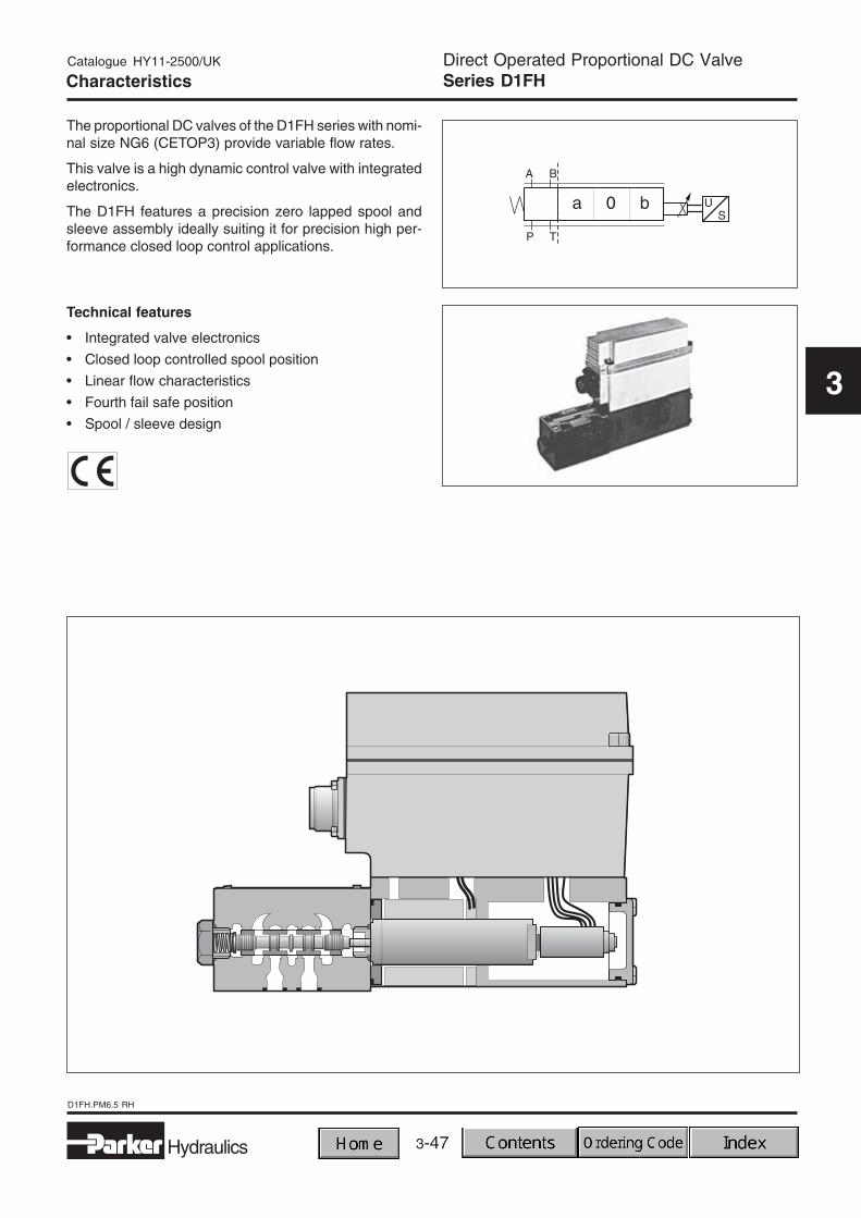
The proportional DC valves of the D1FH series with nomi-nal size NG6 (CETOP3) provide variable flow rates.
This valve is a high dynamic control valve with integratedelectronics.
The D1FH features a precision zero lapped spool andsleeve assembly ideally suiting it for precision high per-formance closed loop control applications.
Technical features
• Integrated valve electronics
• Closed loop controlled spool position
• Linear flow characteristics
• Fourth fail safe position
• Spool / sleeve design

3-48
D1FH.PM6.5 RH
Direct Operated Proportional DC ValveSeries D1FH
Catalogue HY11-2500/UK
3
Ordering Code
D F
DCvalve
Spooltype
Nominalsize
NG06 /CETOP 3
Supplyvoltage24VDC
B
Controlvalve
C
4/4directional
controlvalve
J 00
Voltage /current inputswitchable
Designseries
Flowcontrol
N
SealNBR
(differentseal
compoundby request)
1 H
Code
E50BE50DE50HE50M
Spool typeFlow [l/min]
at ∆p = 35barper metering edge
5102040
E80BE80DE80HE80M
5102040
Please order plug/s separately.See chapter 3 accessories.

3-49
D1FH.PM6.5 RH
Direct Operated Proportional DC ValveSeries D1FH
Catalogue HY11-2500/UK
3
Technical Data
General
Design Direct operated proportional DC valve with integrated power amplifier
Actuation Proportional solenoid
Mounting position optional
Environmental temp. [°C] -20 ... +60
Hydraulics
Pressure medium Hydraulic oil as per DIN 51 524 ... 535, other fluids by request
Viscosity, recommended [mm²/s] 30 ... 80max. admiss. [mm²/s] 20 ... 380
Oil temperature [°C] 0 ... 60
Filtration Permitted contamination class of to achieve with filterpressure medium as per NAS 1638 β x = 75class 7 X = 10
Mounting pattern DIN 24340 / ISO 4401 / CETOP RP121 / NFPA
Operating pressure [bar] Port P, A, B, max. 315; Port T min. 1,4, max. 35
Nominal size DIN NG06
CETOP 03
Weight [kg] 3.7
Nominal flow at ∆p=35barper metering edge [l/min] 5, 10, 20, 40
Drain, max. [l/min] 1.0
Static / Dynamic
Hysteresis [%] < 0.5
Reversible span [%] < 0.1
Sensitivity [%] < 0.1
Response time [ms] 16
Integrated electronics
Supply voltage [V] 21 ... 30
Power consumption [VA] 30
Current requirement [A] 2
Current consumption max. [A] 4
Input signal
Polarity D against E positive corresponds to P-A, B-T, negative corresponds to P-B, A-TVoltage [V] ±10Impedance [kOhm] 100
Current [mA] ±20Impedance [Ohm] 500
Diagnostic output PIN F [V] ±10
Protection class IP65, NEMA 4
Plug 6 + PE DIN 43563
Wiring

3-50
D1FH.PM6.5 RH
Direct Operated Proportional DC ValveSeries D1FH
Catalogue HY11-2500/UK
3
Dynamic response
Characteristic Curves
Operation limits100% Nominal current
Flow characteristicsat ∆p = 35bar per metering edge

3-51
D1FH.PM6.5 RH
Direct Operated Proportional DC ValveSeries D1FH
Catalogue HY11-2500/UK
3
Dimensions
NBR
BK375 4x M5x30 8.1 Nm SK-D1FH-N12DIN 912 12.9
Surface finish

3-52
D1FH.PM6.5 RH
Direct Operated Proportional DC ValveSeries D1FH
Catalogue HY11-2500/UK
3
Notes

3-53
D_1FH.PM6.5 RH
Pilot Operated Proportional DC ValveSeries D*1FH
Catalogue HY11-2500/UK
3
Characteristics
The pilot-operated proportional DC valves series of theD*1FH series are high performance valves with electronicspool position feedback. Valves are available in sizesNG10 to NG32 (CETOP5 to CETOP8).
Typical applications are:High precision and reproducible adjustment of flow rates,applications in rapid / creep speed with spool positionmonitoring for presses and dynamic position and p/Qclosed loop systems.
Technical features• Low leakage
• Very low hysteresis
• Zero lap and overlap spool design available
• Mechanical zero point adjustment for zero lap spools
• High dynamics
• Spool position feedback
• Optional: centre position monitoring

3-54
D_1FH.PM6.5 RH
Pilot Operated Proportional DC ValveSeries D*1FH
Catalogue HY11-2500/UK
3
Code Inlet Drain
1 internal external
2 external external
4 internal internal
5 external internal
Ordering Code
D F
DCvalve
Spooltype
Flow
Code
standard
Monitor switch(plug included)
0
83)
Valve accessoriesNominal size
NG10 / CETOP 5NG16 / CETOP 7NG25 / CETOP 8NG25 / CETOP 8
NG32 / CETOP 10
1
Nominalsize
Code
34891)
11
H
Valveaccessories
Pilot oilconnection
Code
Voltage input0...±10Vstandard
Current input0...±20mA
Current input4...20mA
B
E
S
Electronicvariation
Electronicvariation
3) not for spool E52, B61
0
Designseries
Flowcontrol
Highresponse
SealNBR
(differentseal
compoundby request)
N
Code
E01
E02
B31
B32
B11
B12
Spool type
overlap
zerolap 2)
E52
B61
QB = QA /2
QB = QA /2
QB = QA /2
2) not for D111FH
1) with enlarged connectionsØ 32mm
Flow [l/min]at ∆p 5bar per metering edge
D31 D41 D81/91 D111
Code
A
B
C
E
F
H
L
55 - - -
- 105 - -
80 140 - -
- 190 250 -
- 240 310 -
- - 400 500
- - - 1000
Please order plug/s separately.See chapter 3 accessories.

3-55
D_1FH.PM6.5 RH
Pilot Operated Proportional DC ValveSeries D*1FH
Catalogue HY11-2500/UK
3
Technical Data
General
Design Pilot-operated proportional DC valve with integrated power amplifier
Actuation Proportional solenoid
Mounting position optional
Environmental temp. [°C] -20...+60
Hydraulics
Pressure medium Hydraulic oil as per DIN 51 524 ... 535, other fluids by request
Viscosity, recommended [mm²/s] 30 ... 80max. admiss. [mm²/s] 20 ... 380
Oil temperature [°C] 0 ... 60
Filtration Permissible contamination class of to achieve with filterpressure medium as per NAS 1638 β x = 75
Pilot stage Class 7 X = 5Main stage Class 9 X = 15
Mounting pattern DIN 24340 / ISO 4401 / CETOP RP121 / NFPAOperating pressure [bar] Port P, T, A, B, X max. 350 bar, Port Y max. 10 bar
Nominal size DIN NG10 NG16 NG25 NG32
CETOP 05 07 08 10
Weight [kg] 8.1 11.6 20.7 62
Nominal flow at ∆p=5barper metering edge [l/min] 80 240 400 1000
Max. flow [/min] 170 420 900 2000
Drain1) (140bar) [l/min] 0.1 0.2 0.6 1.0
Pilot stage
Pilot pressure [bar] 20 - 350 (optimal dynamics at 70)
Pilot volume req. (const.) [l/min] < 1.2
Pilot volume requirementfor min. step response [l/min] 2.0 4.1 9.0 18.0
Static / Dynamic
Hysteresis [%] < 0.1
Threshold [%] < 0.1
Sensitivity [%] < 0.05
Response time [ms] 25 45 65 150
Integrated electronics (D*1FH)
Supply voltage [V] 18 ... 30
Power consumption [VA] 30
Current consumption max. [A] 2
Starting current (0.5ms) [A] 7
Input signalVoltage [V] ±10 (0...+10V → P–B) 2)
Impedance [kOhm] 100
Current [mA] ±20 (0...+20mA → P–B) 2)
Impedance [Ohm] 500
Current [mA] 4...20 (12...4mA → P–B)Impedance [Ohm] 500
Diagnostic output Pin F [V] ±10
Protection class IP54
Temperature drift [%/°C] 0.005
Plug connector 6 + PE DIN 43563
1) overlap spool2) inverse polarity by request

3-56
D_1FH.PM6.5 RH
Pilot Operated Proportional DC ValveSeries D*1FH
Catalogue HY11-2500/UK
3
Display is green Normal operation
Display offSupply voltage is outside the
permissible range of 18 ... 30V
Display is red Control error
Electronics
Enable inputThe power stage is activated via pin C (enable input).
Supply voltage monitoringIf the minimal supply voltage drops below, it is internallymonitored and displayed via the status LED.
Wiring
Arrangement of the potentiometers
Control monitoringA control error is indicated if there is an error in the con-trol circuit of the valve.
Control system flow chart, valve electronics
Spindle trimmerfor zero pointcompensation
LED
Diagnosticsfor spoolstroke

3-57
D_1FH.PM6.5 RH
Pilot Operated Proportional DC ValveSeries D*1FH
Catalogue HY11-2500/UK
3
Characteristic Curves
Characteristic flow linesat ∆p = 5bar per metering edge
Spool type E01, E02 Spool type E52
Spool type B31, B32 Spool type B61

3-58
D_1FH.PM6.5 RH
Pilot Operated Proportional DC ValveSeries D*1FH
Catalogue HY11-2500/UK
3
Characteristic Curves
Step response
D31FH
D81/91FH
D41FH
D111FH

3-59
D_1FH.PM6.5 RH
Pilot Operated Proportional DC ValveSeries D*1FH
Catalogue HY11-2500/UK
3
Dynamic response
D111FH
Characteristic Curves
D41FH
D31FH
D81/91FH

3-60
D_1FH.PM6.5 RH
Pilot Operated Proportional DC ValveSeries D*1FH
Catalogue HY11-2500/UK
3
Pilot Flow
Pilot connection
D31FH
D41FH
D111FH
D81/91FH

3-61
D_1FH.PM6.5 RH
Pilot Operated Proportional DC ValveSeries D*1FH
Catalogue HY11-2500/UK
3
Dimensions
D31FH
D41FH
NBR
BK385 4x M6x40 13.6 Nm SK-D31FH-N35DIN 912 12.9
Surface finish
NBR
2x M6x55 13.6 NmBK320 4x M10x60 65 Nm SK-D41FH-N35
DIN 912 12.9
Surface finish

3-62
D_1FH.PM6.5 RH
Pilot Operated Proportional DC ValveSeries D*1FH
Catalogue HY11-2500/UK
3
Dimensions
D81/91FH
D111FH
NBR
BK360 6x M12x95 115 Nm SK-D91FW-N10DIN 912 12.9
Surface finish
NBR
BK386 6x M20x90 553 Nm SK-D111FW-N10DIN 912 12.9
Surface finish

3-63
Accessories 3.PM6.5 RH
Catalogue HY11-2500/UK
3
Solenoid connector D*FW, D*FS, WL*, RL*
Proportional DC ValvesAccessories
Description Variation Order No.
EN 175301-803 2+PE PG 9 black B 5001710
EN 175301-803 2+PE PG 9 grey A 5001711
EN 175301-803 2+PE PG 11 black B 5001716
EN 175301-803 2+PE PG 11 grey A 5001717
Feedback connector D*FS, WL*06*R*
Description Order No.
M12 / 5pin 5004109
Monitor switch connector D*1FW / D*1FT / D*1FS / D*1FH
Central connector D*FT / D*FH / D*FX
Description Order No.
DIN 43563 6+PE 5004072
Plugs
Description Order No.
M12 / 5pin 5004109
3-64
Accessories 3.PM6.5 RH
Catalogue HY11-2500/UK
3
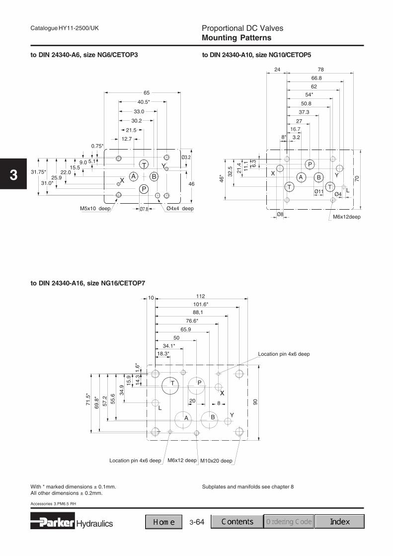
to DIN 24340-A6, size NG6/CETOP3
to DIN 24340-A16, size NG16/CETOP7
With * marked dimensions ± 0.1mm.All other dimensions ± 0.2mm.
to DIN 24340-A10, size NG10/CETOP5
Subplates and manifolds see chapter 8
Proportional DC ValvesMounting Patterns

3-65
Accessories 3.PM6.5 RH
Catalogue HY11-2500/UK
3
to DIN 24340-A25, size NG25/CETOP8
With * marked dimensions ± 0.1mm.All other dimensions ± 0.2mm.
to DIN 24340-A32, size NG32/CETOP10
Proportional DC ValvesMounting Patterns
Subplates and manifolds see chapter 8

3-66
Accessories 3.PM6.5 RH
Catalogue HY11-2500/UK
3
Notes