catalycatalytic distillationtic distillation - · pdf fileintegration of unit operations in...
TRANSCRIPT
Modern Methods in Heterogeneous Catalysis ResearchFritz Haber Institute, Berlin, 14 November 2003
Kai Sundmacher1,2
1 Max-Planck-Institute for Dynamics of Complex Technical Systems Sandtorstraße 1, 39106 Magdeburg, Germany
2 Otto-von-Guericke-University Magdeburg, Process Systems Engineering Universitätsplatz 2, 39106 Magdeburg, Germany
Catalytic DistillationCatalytic Distillation

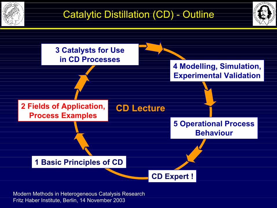
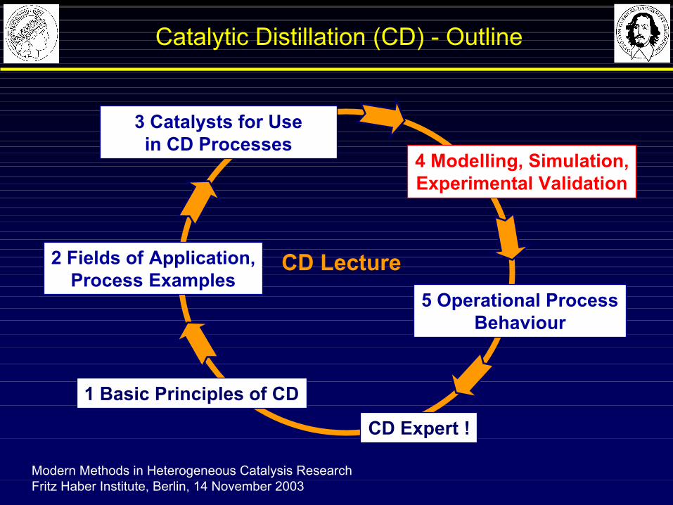
Catalytic Distillation (CD) - Outline
Modern Methods in Heterogeneous Catalysis ResearchFritz Haber Institute, Berlin, 14 November 2003
4 Modelling, Simulation,Experimental Validation
CD Expert !
3 Catalysts for Usein CD Processes
2 Fields of Application,Process Examples
5 Operational ProcessBehaviour
1 Basic Principles of CD
CD Lecture
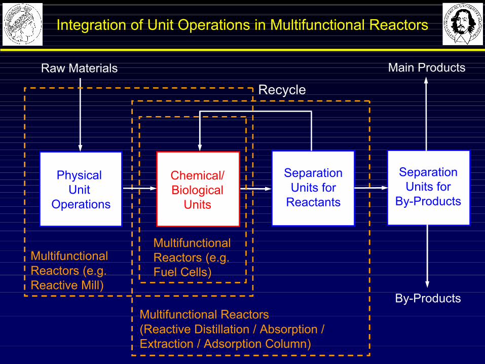
Integration of Unit Operations in Multifunctional Reactors
Physical Unit
Operations
Chemical/Biological
Units
Raw Materials
SeparationUnits for
Reactants
By-Products
SeparationUnits for
By-Products
Main Products
MultifunctionalReactors (e.g. Reactive Mill)
Multifunctional Reactors(Reactive Distillation / Absorption / Extraction / Adsorption Column)
MultifunctionalReactors (e.g. Fuel Cells)
Recycle

Possible Benefits from Multifunctional Reactor Concepts
Synergetic interactions of chemical and physical unit operations may lead to:
á increase of productivity from process intensification
á increase of selectivity of reactions and/or separations
á reduction of by-products and waste materials
á more efficient (in situ) use of energy
á inherent safety
á improved environmental compatibility (e.g. by avoidance of hazardous solvents etc.).
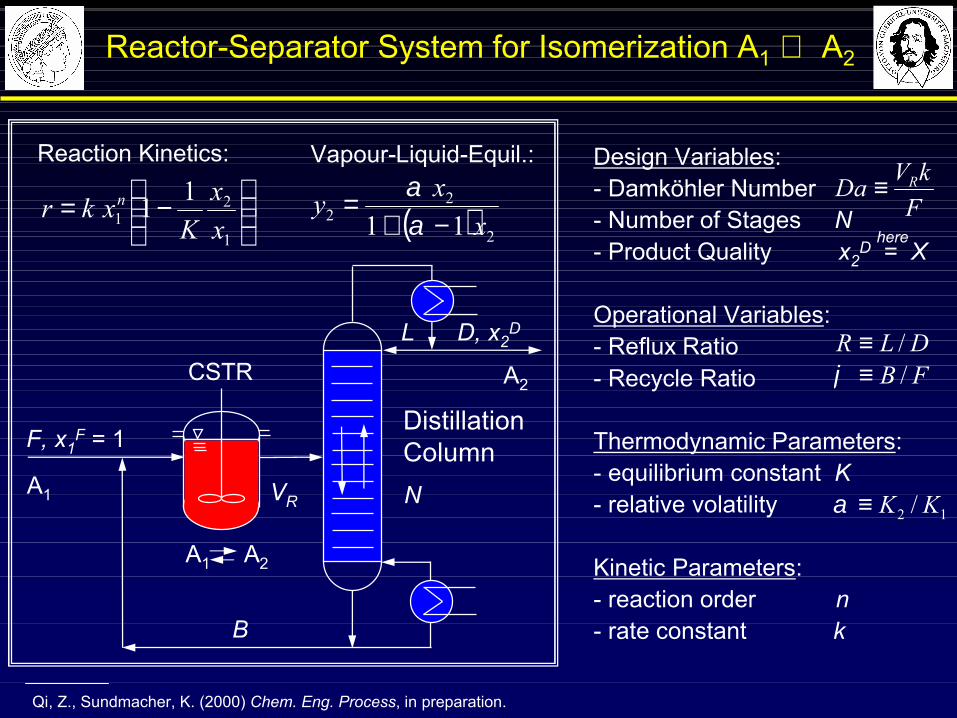
Design Variables:- Damköhler Number - Number of Stages N- Product Quality x2
D = X
Operational Variables:- Reflux Ratio - Recycle Ratio
Thermodynamic Parameters:- equilibrium constant K- relative volatility
Kinetic Parameters: - reaction order n- rate constant k
FkVDa R≡
12 / KK≡α
FB /≡ϕDLR /≡
−=
1
21
11 xx
Kxkr n
Reactor-Separator System for Isomerization A1 ⇔ A2
CSTR
B
DistillationColumnF, x1
F = 1
D, x2DL
VRVR N
( ) 2
22 11
x
xy−+
=αα
Reaction Kinetics: Vapour-Liquid-Equil.:
A1 A2
A2
A1
here
Qi, Z., Sundmacher, K. (2000) Chem. Eng. Process, in preparation.
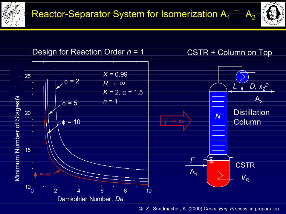
0 2 4 6 8 1010
15
20
25 X = 0.99R K = 2, α = 1.5n = 1
ϕ = 10
ϕ =
ϕ = 5
ϕ = 2
Min
imum
Num
ber o
f Sta
ges,
N =
Nm
in
Damköhler Number, Da
Design for Reaction Order n = 1
ϕ = ∞
CSTR + Column on Top
∞
→ ∞
DistillationColumn
D, x2DL
VR
N
A2
CSTRFA1
Reactor-Separator System for Isomerization A1 ⇔ A2
Qi, Z., Sundmacher, K. (2000) Chem. Eng. Process, in preparation
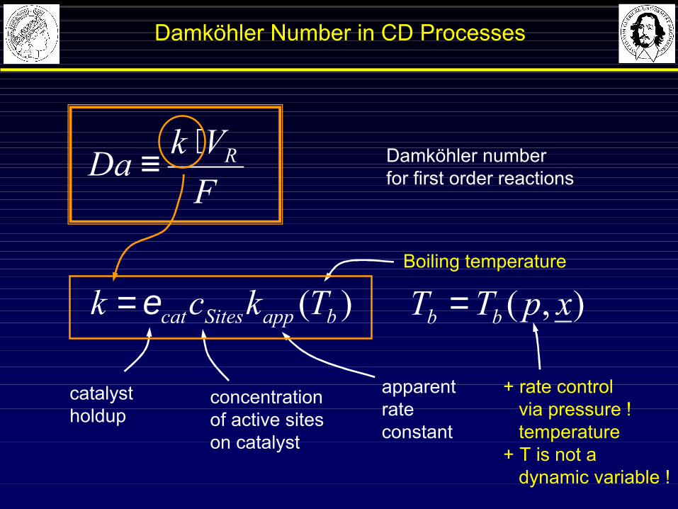
Damköhler Number in CD Processes
FVkDa R⋅
≡
)( bappSitescat Tkck ε=
Damköhler numberfor first order reactions
catalystholdup
concentrationof active siteson catalyst
apparentrateconstant
Boiling temperature
),( xpTT bb =
+ rate controlvia pressure !temperature
+ T is not a dynamic variable !

0,001 0,01 0,1 1 10 1000,0
0,2
0,4
0,6
0,8
1,0
50
510
12
20
N =100
α = 1.5 K = 2, n = 1R = 10
Con
vers
ion,
X
Da / N
Reactive Distillation Column Influence of Reaction / Separation
DL
N
F
R = L / D Xeq = 66.6 %
(CSTR)
NTSMcA
NFkV
NDa sitescatcR ε
∝=
TotalReboiler
Reaction / Separation:
420 0.2)20( === xNDaopt
X = 92.5 %
Reactive Distillation Column for Isomerization A1 ⇔ A2
Qi, Z., Sundmacher, K. (2000) Chem. Eng. Process, in preparation.
ReactiveAzeotrope
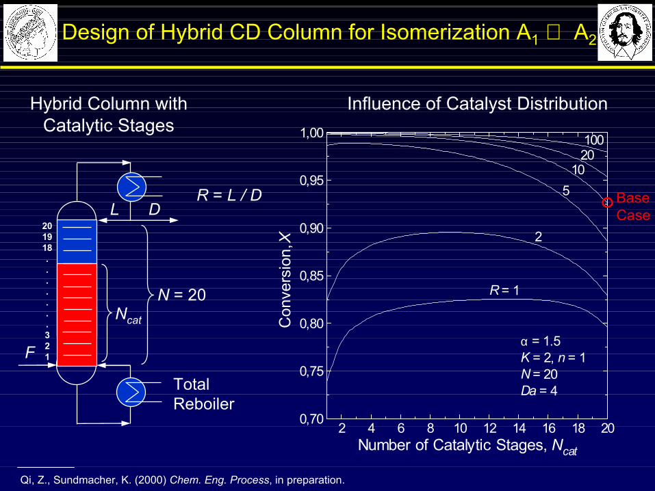
2 4 6 8 10 12 14 16 18 200,70
0,75
0,80
0,85
0,90
0,95
1,00
1020
5
100
R = 1
2
α = 1.5 K = 2, n = 1N = 20Da = 4
Con
vers
ion,
X
Number of Catalytic Stages, Ncat
Influence of Catalyst DistributionHybrid Column with Catalytic Stages
DL
N = 20
F
R = L / D
TotalReboiler
Ncat
201918.......321
BaseCase
Design of Hybrid CD Column for Isomerization A1 ⇔ A2
Qi, Z., Sundmacher, K. (2000) Chem. Eng. Process, in preparation.

Reactive Batch Distillation: MeOH + IA ⇔ TAME
Thiel, C.; Sundmacher, K.; Hoffmann, U. (1997) Chem. Eng. Sci. 52, 993-1005.
Heating policy:V / V0 = H / H0
Liquid phase:Holdup HComposition xi
MeOHL + IAL TAMEL
MeOHV IAV TAMEV
Qreb
Vapour phase:Vapour Flow VComposition yi
FCR
LCRH+
Catalyst: Acidic Ion Exchange Resin (Vcat, cH+)
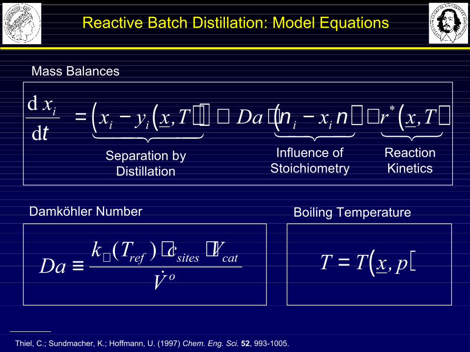
( )( ) ( ) ( )d d
x x y x T Da x r x Tii i i iτ
ν ν= − + ⋅ − ⋅, ,*
1 244 344 1 24 34 123Separation by
DistillationReactionKinetics
Influence ofStoichiometry
Dak T c V
Vref sites cat
o≡⋅ ⋅+ ( )&
Damköhler Number Boiling Temperature
( )T T x p= ,
Thiel, C.; Sundmacher, K.; Hoffmann, U. (1997) Chem. Eng. Sci. 52, 993-1005.
Reactive Batch Distillation: Model Equations
Mass Balances
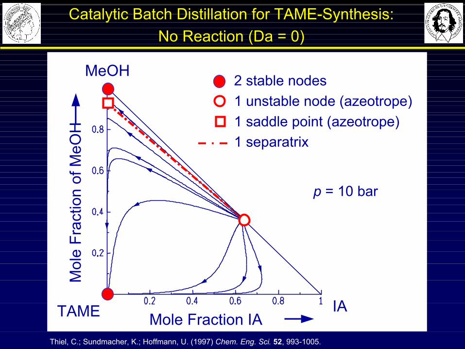
p = 10 bar
2 stable nodes1 unstable node (azeotrope)1 saddle point (azeotrope)1 separatrix
Mol
e Fr
actio
nof
MeO
H
Mole Fraction IATAME IA
MeOH
Thiel, C.; Sundmacher, K.; Hoffmann, U. (1997) Chem. Eng. Sci. 52, 993-1005.
Catalytic Batch Distillation for TAME-Synthesis: No Reaction (Da = 0)
Thiel, C.; Sundmacher, K.; Hoffmann, U. (1997) Chem. Eng. Sci. 52, 993-1005.
p = 10 bar
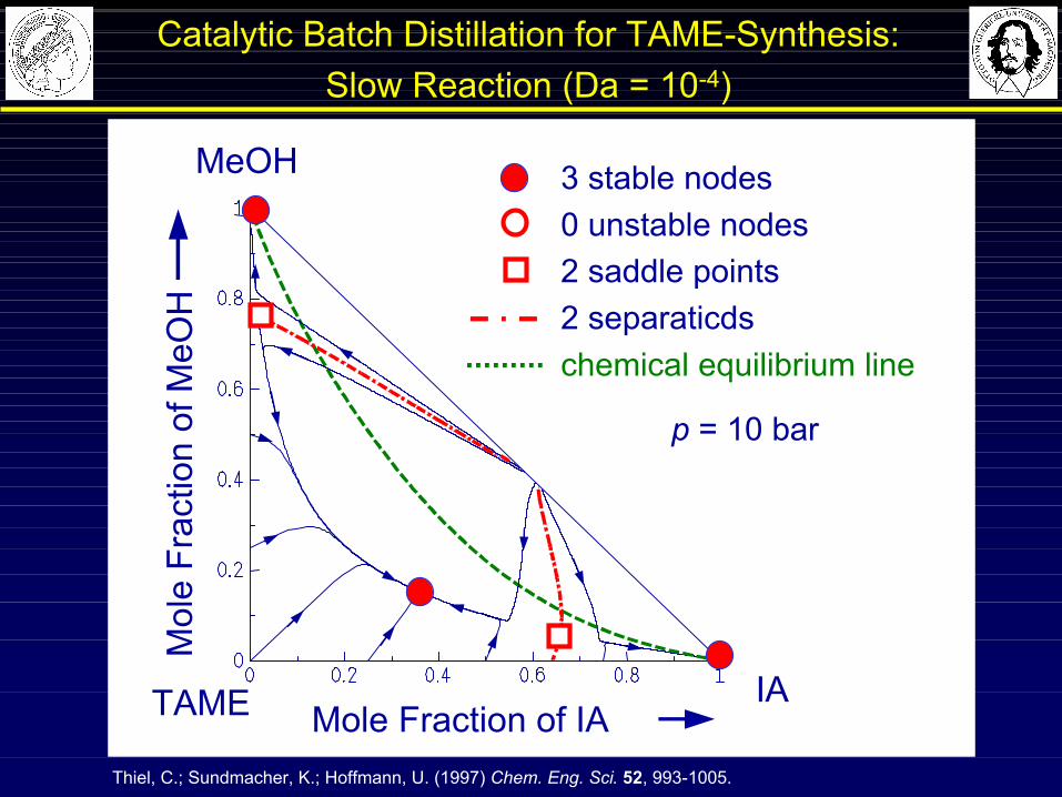
3 stable nodes0 unstable nodes2 saddle points2 separaticdschemical equilibrium line
Mol
enbr
uch
Met
hano
l
Molenbruch IsoamylenTAME IA
MeOH
Catalytic Batch Distillation for TAME-Synthesis: Slow Reaction (Da = 10-4)
Mol
eFr
actio
nof
MeO
H
Mole Fraction of IA
Thiel, C.; Sundmacher, K.; Hoffmann, U. (1997) Chem. Eng. Sci. 52, 993-1005.
Mole Fraction of IA TAME IA
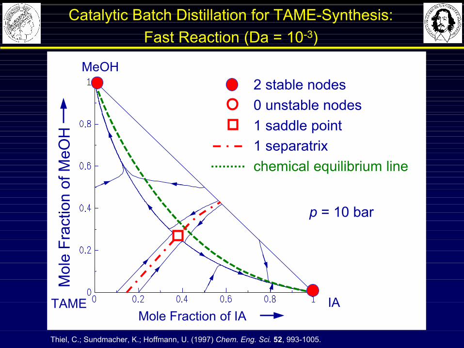
MeOH2 stable nodes0 unstable nodes1 saddle point1 separatrixchemical equilibrium line
p = 10 bar
Catalytic Batch Distillation for TAME-Synthesis: Fast Reaction (Da = 10-3)
Mol
eFr
actio
nof
MeO
H

Mol
enbr
uch
Met
hano
l
Molenbruch IsoamylenTAME IA
MeOH2 stabile nodes0 unstable nodes1 saddle point1 separatixchemical equilibrium line
p = 10 bar
Thiel, C.; Sundmacher, K.; Hoffmann, U. (1997) Chem. Eng. Sci. 52, 993-1005.
Catalytic Batch Distillation for TAME-Synthesis: Reaction in Equilibrium (Da > 1)
Mol
eFr
actio
nof
MeO
H
Mole Fraction of IA
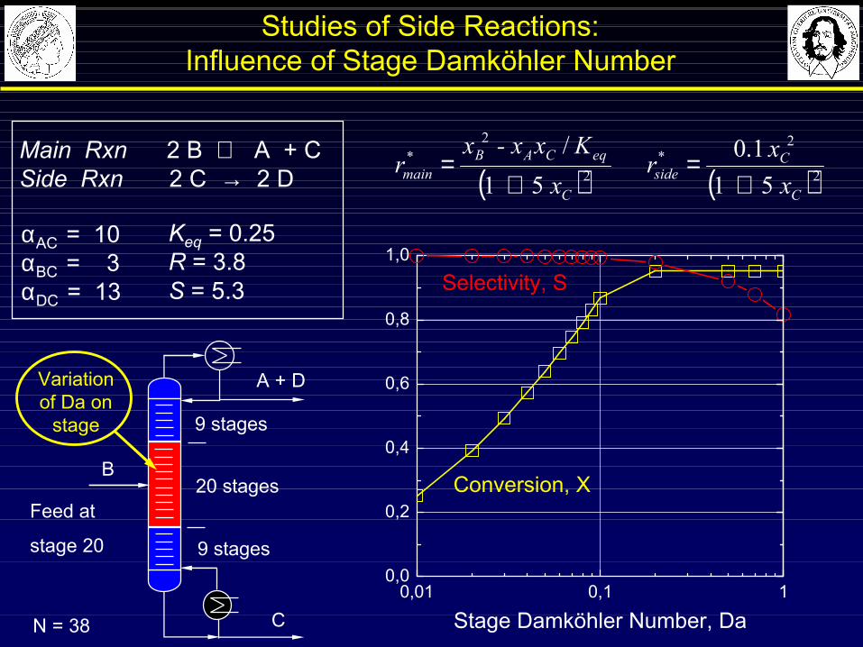
Main Rxn 2 B ⇔ A + CSide Rxn 2 C → 2 D
αAC = 10αBC = 3αDC = 13
20 stages
9 stages
9 stages
Feed at
stage 20
Variationof Da on
stage
Keq = 0.25R = 3.8S = 5.3
Studies of Side Reactions: Influence of Stage Damköhler Number
( ) ( )2
2*
2
2*
51 1.0
51/
C
C
sideC
eqCA B
main x x r
x Kx - xx
r+
=+
=
A + D
C
B
0,01 0,1 10,0
0,2
0,4
0,6
0,8
1,0
Selectivity, S
Conversion, X
Stage Damköhler Number, Da
N = 38
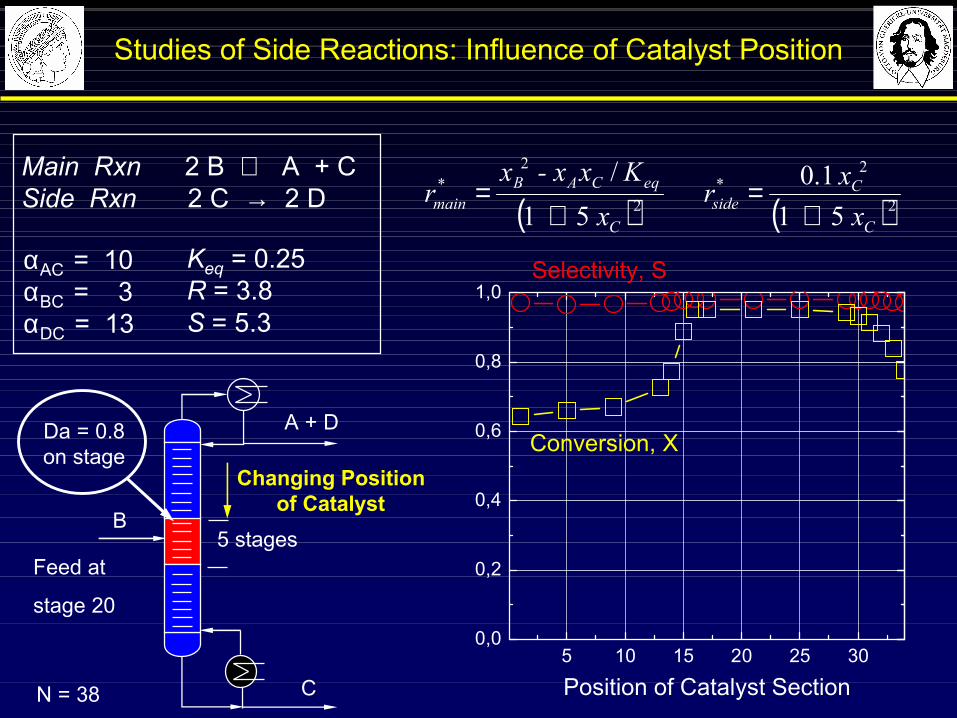
5 stagesFeed at
stage 20
Da = 0.8 on stage
A + D
C
B
Studies of Side Reactions: Influence of Catalyst Position
Changing Positionof Catalyst
5 10 15 20 25 300,0
0,2
0,4
0,6
0,8
1,0Selectivity, S
Conversion, X
Position of Catalyst Section
N = 38
Main Rxn 2 B ⇔ A + CSide Rxn 2 C → 2 D
αAC = 10αBC = 3αDC = 13
Keq = 0.25R = 3.8S = 5.3
( ) ( )2
2*
2
2*
51 1.0
51/
C
C
sideC
eqCA B
main x x r
x Kx - xx
r+
=+
=
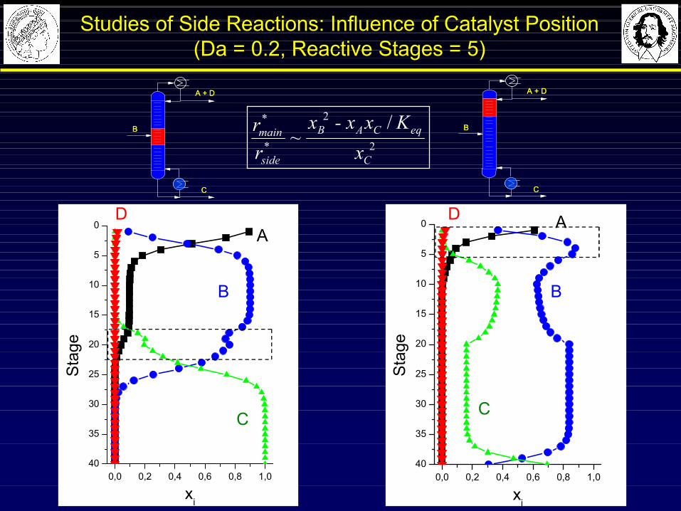
Studies of Side Reactions: Influence of Catalyst Position(Da = 0.2, Reactive Stages = 5)
A + D
C
B
A + D
C
B
40
35
30
25
20
15
10
5
0
0,0 0,2 0,4 0,6 0,8 1,0
xi
Sta
ge
DA
B
C
40
35
30
25
20
15
10
5
0
0,0 0,2 0,4 0,6 0,8 1,0
xi
Sta
ge
D A
B
C
A + D
C
B
A + D
C
B
2
2
*
* /~
C
eqCA B
side
main
xKx - xx
rr
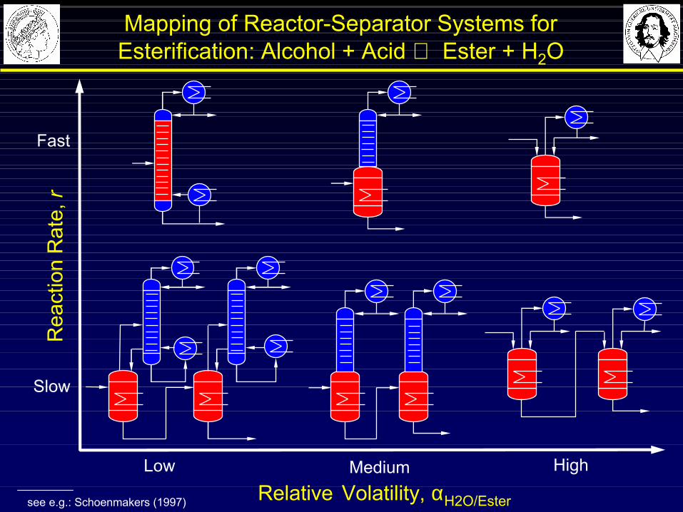
Relative Volatility, αH2O/Ester
Low HighMedium
Fast
Slow
Rea
ctio
nR
ate,
r
see e.g.: Schoenmakers (1997)
Mapping of Reactor-Separator Systems for Esterification: Alcohol + Acid ⇔ Ester + H2O
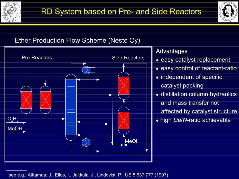
RD System based on Pre- and Side Reactors
see e.g.: Aittamaa, J., Eilos, I., Jakkula, J., Lindqvist, P., US 5 637 777 (1997)
Advantagesl easy catalyst replacementl easy control of reactant-ratiol independent of specific
catalyst packingl distillation column hydraulics
and mass transfer notaffected by catalyst structure
l high Da/N-ratio achievableMeOH
CxHy
MeOH
Side-ReactorsPre-Reactors
Ether Production Flow Scheme (Neste Oy)
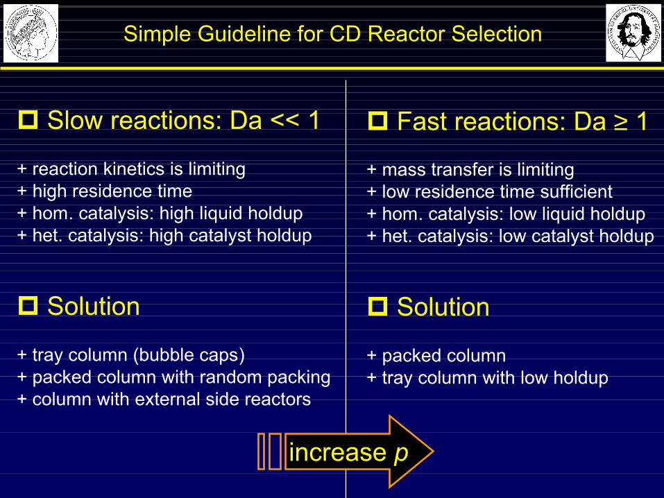
Simple Guideline for CD Reactor Selection
p Slow reactions: Da << 1
+ reaction kinetics is limiting+ high residence time+ hom. catalysis: high liquid holdup+ het. catalysis: high catalyst holdup
p Solution
+ tray column (bubble caps)+ packed column with random packing+ column with external side reactors
p Fast reactions: Da ≥ 1
+ mass transfer is limiting+ low residence time sufficient+ hom. catalysis: low liquid holdup+ het. catalysis: low catalyst holdup
p Solution
+ packed column+ tray column with low holdup
increase p
Catalytic Distillation (CD) - Outline
4 Modelling, Simulation,Experimental Validation
CD Expert !
3 Catalysts for Usein CD Processes
2 Fields of Application,Process Examples
5 Operational ProcessBehaviour
1 Basic Principles of CD
Modern Methods in Heterogeneous Catalysis ResearchFritz Haber Institute, Berlin, 14 November 2003
CD Lecture
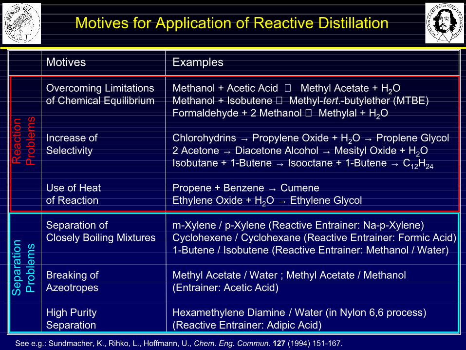
Motives for Application of Reactive Distillation
Motives Examples
Overcoming Limitations Methanol + Acetic Acid ⇔ Methyl Acetate + H2Oof Chemical Equilibrium Methanol + Isobutene ⇔ Methyl-tert.-butylether (MTBE)
Formaldehyde + 2 Methanol ⇔ Methylal + H2O
Increase of Chlorohydrins → Propylene Oxide + H2O → Proplene GlycolSelectivity 2 Acetone → Diacetone Alcohol → Mesityl Oxide + H2O
Isobutane + 1-Butene → Isooctane + 1-Butene → C12H24
Use of Heat Propene + Benzene → Cumeneof Reaction Ethylene Oxide + H2O → Ethylene Glycol
Separation of m-Xylene / p-Xylene (Reactive Entrainer: Na-p-Xylene)Closely Boiling Mixtures Cyclohexene / Cyclohexane (Reactive Entrainer: Formic Acid)
1-Butene / Isobutene (Reactive Entrainer: Methanol / Water)
Breaking of Methyl Acetate / Water ; Methyl Acetate / MethanolAzeotropes (Entrainer: Acetic Acid)
High Purity Hexamethylene Diamine / Water (in Nylon 6,6 process)Separation (Reactive Entrainer: Adipic Acid)
Rea
ctio
nP
robl
ems
Sep
arat
ion
Pro
blem
s
See e.g.: Sundmacher, K., Rihko, L., Hoffmann, U., Chem. Eng. Commun. 127 (1994) 151-167.
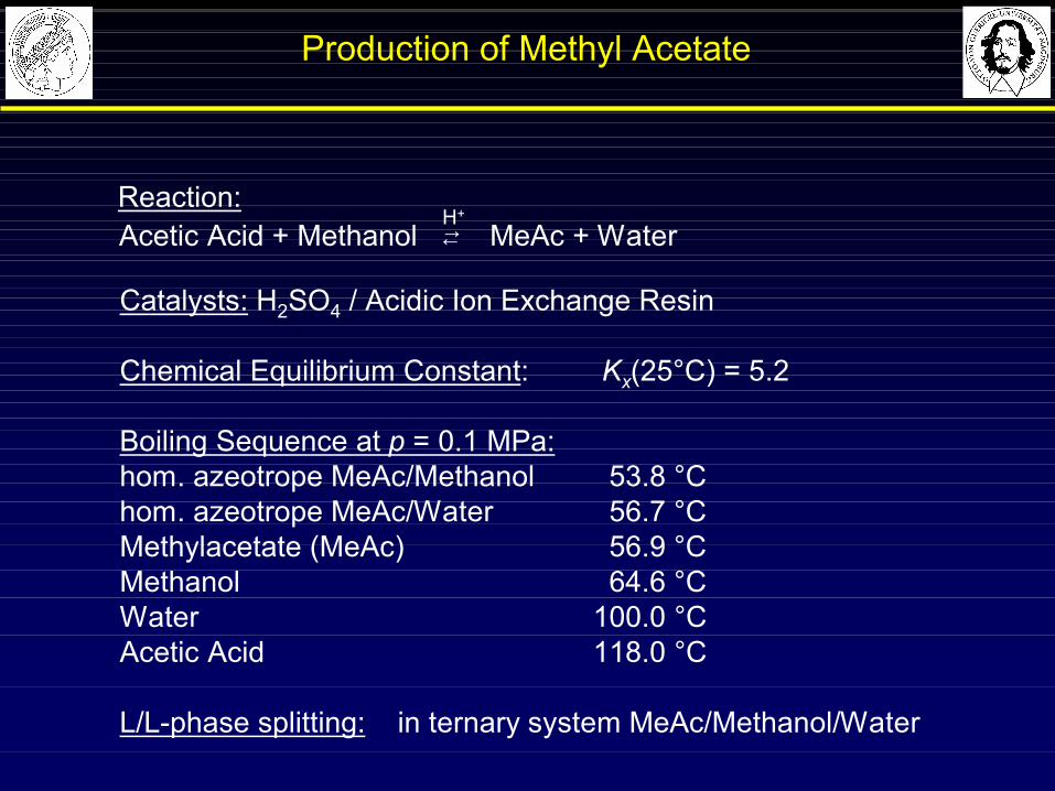
Production of Methyl Acetate
H+
Acetic Acid + Methanol MeAc + Water←→Reaction:
Catalysts: H2SO4 / Acidic Ion Exchange Resin
Chemical Equilibrium Constant: Kx(25°C) = 5.2
Boiling Sequence at p = 0.1 MPa:hom. azeotrope MeAc/Methanol 53.8 °Chom. azeotrope MeAc/Water 56.7 °CMethylacetate (MeAc) 56.9 °CMethanol 64.6 °C Water 100.0 °CAcetic Acid 118.0 °C
L/L-phase splitting: in ternary system MeAc/Methanol/Water

Acetic AcidMethanol
H2SO4 (Cat.)
Rea
ctor
MethylAcetate
High Boilers
Water +H2SO4
Ext
ract
ive
Dis
tilla
tion
Ext
ract
ion
Dis
tilla
tion
Aze
otro
pic
Dis
tilla
tion
Dis
tilla
tion
Dis
tilla
tion
Dis
tilla
tion
Dis
tilla
tion
PhaseSep.
WaterEthyleneGlycol
Acetic Acid
Methanol
Ethyl-acetate Water
Dis
tilla
tion
Production of Methyl Acetate (Conventional Process)
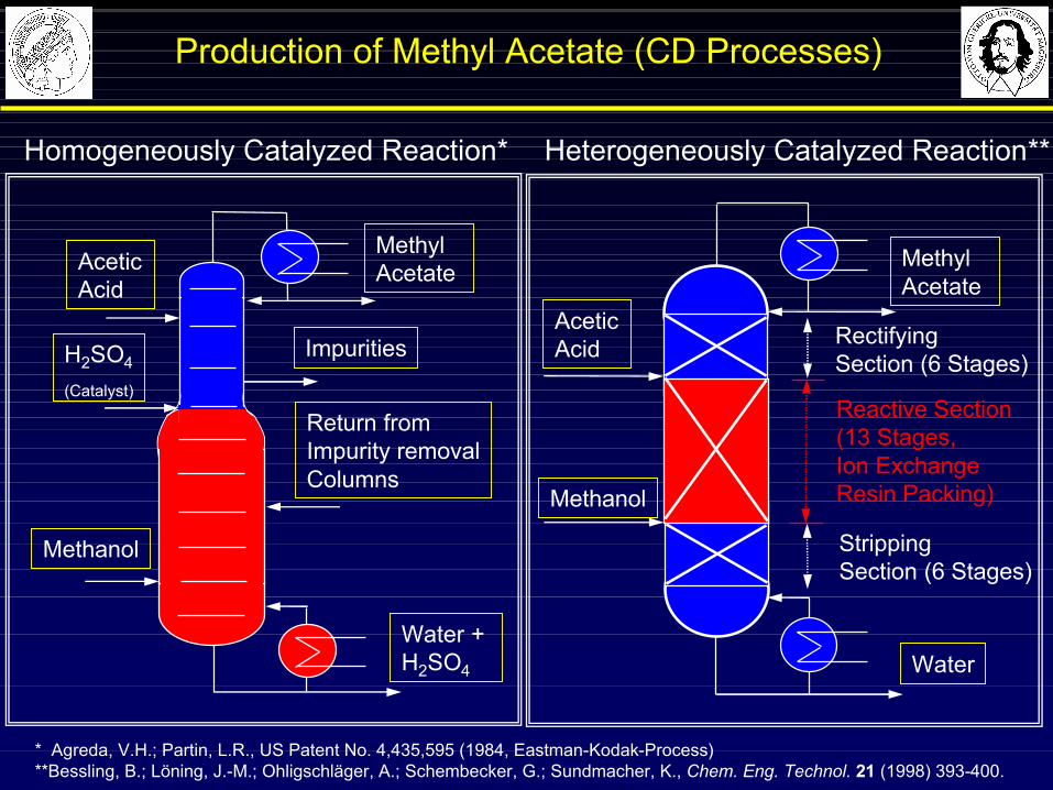
Homogeneously Catalyzed Reaction* Heterogeneously Catalyzed Reaction**
* Agreda, V.H.; Partin, L.R., US Patent No. 4,435,595 (1984, Eastman-Kodak-Process)**Bessling, B.; Löning, J.-M.; Ohligschläger, A.; Schembecker, G.; Sundmacher, K., Chem. Eng. Technol. 21 (1998) 393-400.
Methyl Acetate
Acetic Acid
Water
Methanol
Reactive Section (13 Stages,Ion Exchange Resin Packing)
RectifyingSection (6 Stages)
Stripping Section (6 Stages)
Methanol
Acetic Acid
Methyl Acetate
Water + H2SO4
H2SO4
(Catalyst)
Impurities
Return from Impurity removalColumns
Production of Methyl Acetate (CD Processes)
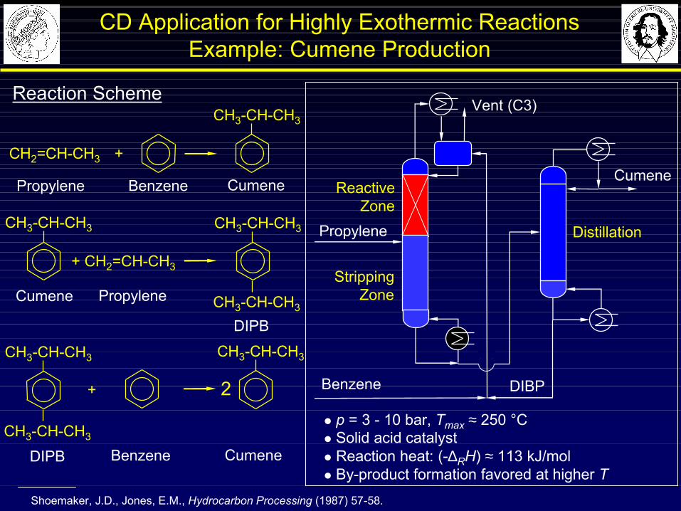
CD Application for Highly Exothermic ReactionsExample: Cumene Production
Shoemaker, J.D., Jones, E.M., Hydrocarbon Processing (1987) 57-58.
Reaction Scheme
l p = 3 - 10 bar, Tmax ≈ 250 °Cl Solid acid catalystl Reaction heat: (-∆RH) ≈ 113 kJ/moll By-product formation favored at higher T
Benzene
Cumene
Propylene
ReactiveZone
StrippingZone
Distillation
Vent (C3)
DIBP
CH3-CH-CH3
CH2=CH-CH3 +
Propylene Benzene
CH3-CH-CH3
+ CH2=CH-CH3
Cumene Propylene
DIPB
CH3-CH-CH3
CH3-CH-CH3
BenzeneDIPB
+
Cumene
2
CH3-CH-CH3
CH3-CH-CH3
CH3-CH-CH3
Cumene
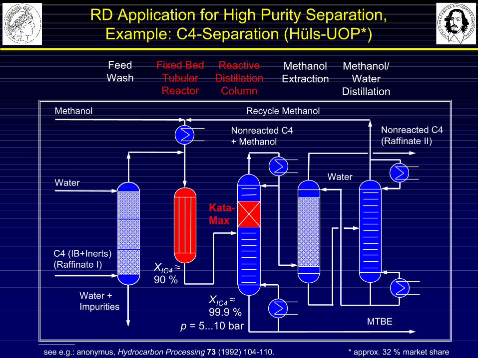
FeedWash
MethanolExtraction
Methanol/Water
Distillation
Fixed BedTubularReactor
ReactiveDistillationColumn
see e.g.: anonymus, Hydrocarbon Processing 73 (1992) 104-110. * approx. 32 % market share
C4 (IB+Inerts)(Raffinate I)
Water
Methanol
Water +Impurities
Recycle Methanol
Nonreacted C4(Raffinate II)
Nonreacted C4 + Methanol
Water
MTBE
XIC4 ≈90 %
XIC4 ≈99.9 %
p = 5...10 bar
Kata-Max
RD Application for High Purity Separation,Example: C4-Separation (Hüls-UOP*)

Catalytic Distillation (CD) - Outline
4 Modelling, Simulation,Experimental Validation
CD Expert !
3 Catalysts for Usein CD Processes
2 Fields of Application,Process Examples
5 Operational ProcessBehaviour
1 Basic Principles of CD
Modern Methods in Heterogeneous Catalysis ResearchFritz Haber Institute, Berlin, 14 November 2003
CD Lecture

Catalytic Packings: Aspects of Selection
CatalyticPacking
Reaction Rate(Catalyst Holdup: εcat)
Mass TransferEfficiency
(Number of TheoreticalStages: NTSM)
Hydraulic Capacity(Void Fraction: 1 - εcat)
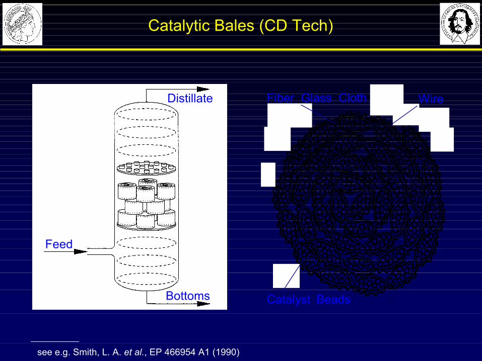
Catalytic Bales (CD Tech)
see e.g. Smith, L. A. et al., EP 466954 A1 (1990)
Catalyst Beads
Fiber Glass Cloth Wire
Feed
Bottoms
Distillate
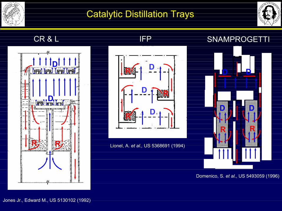
Catalytic Distillation Trays
D
RR
DD
D
Domenico, S. et al., US 5493059 (1996)
SNAMPROGETTI
Lionel, A. et al., US 5368691 (1994)
IFP
RD
R
R
D
D
Jones Jr., Edward M., US 5130102 (1992)
CR & L
R R
D
D
R R
D
D
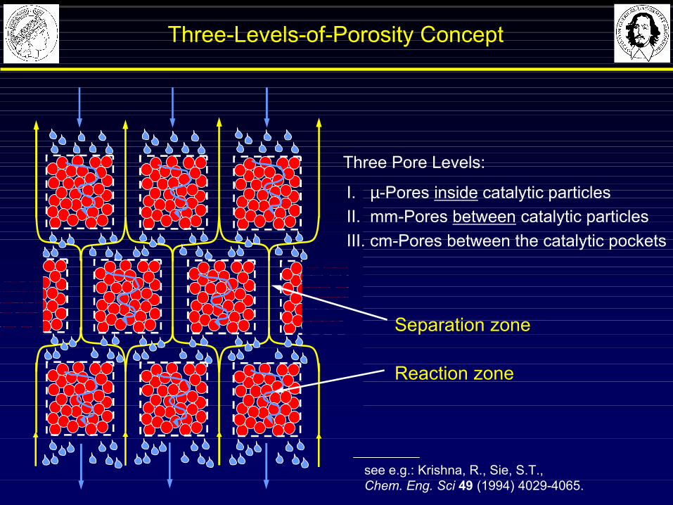
Three-Levels-of-Porosity Concept
see e.g.: Krishna, R., Sie, S.T., Chem. Eng. Sci 49 (1994) 4029-4065.
I. µ-Pores inside catalytic particlesII. mm-Pores between catalytic particlesIII. cm-Pores between the catalytic pockets
Three Pore Levels:
Separation zone
Reaction zone
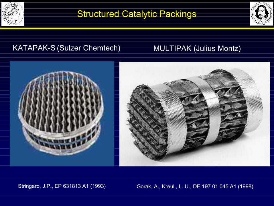
Structured Catalytic Packings
KATAPAK-S (Sulzer Chemtech)
Stringaro, J.P., EP 631813 A1 (1993)
MULTIPAK (Julius Montz)
Gorak, A., Kreul., L. U., DE 197 01 045 A1 (1998)

Hydrodynamic Behaviour of StructuredCatalytic Packing
§ Gas flow through open channels (1)
§ Liquid flow through open channels and catalyst bags (2)
§ Liquid holdup in open channels increases resistance for gas flow
§ Load point determines max. liquid flow through catalyst bags
Adopted from: Hoffmann, A., Gorak, A. (2000)Treffen der GVC-Fachausschüsse in Wernigerode.
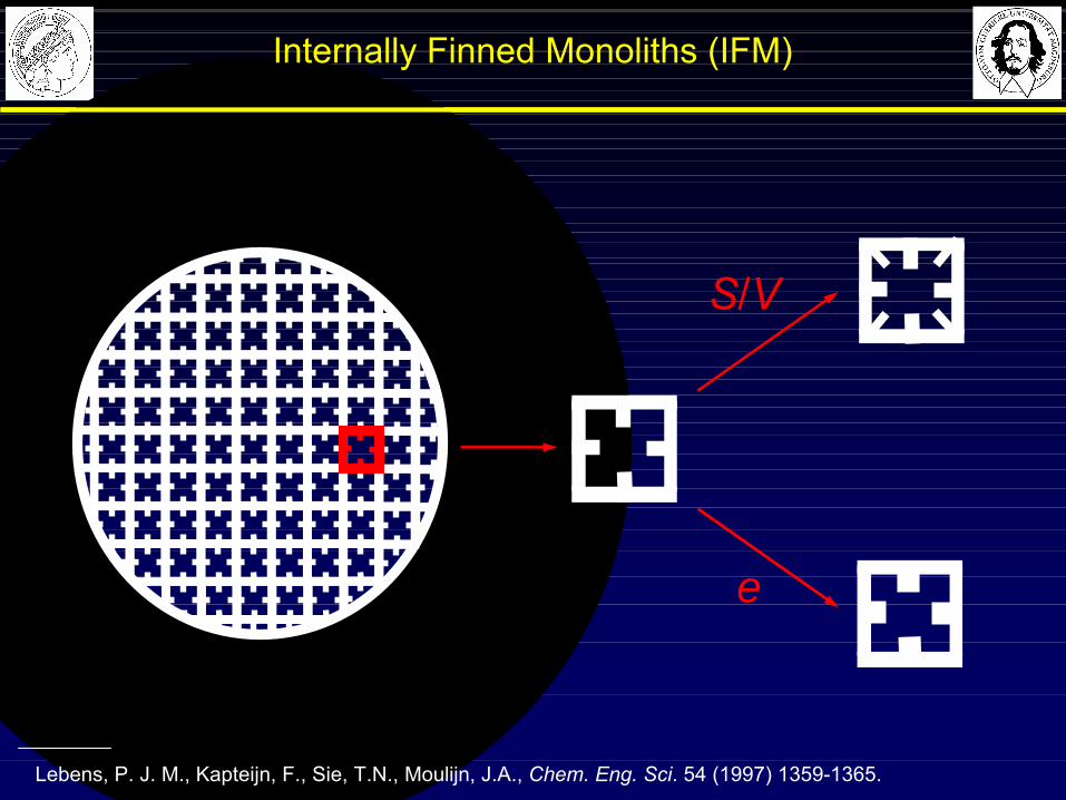
Internally Finned Monoliths (IFM)
Lebens, P. J. M., Kapteijn, F., Sie, T.N., Moulijn, J.A., Chem. Eng. Sci. 54 (1997) 1359-1365.
ε
S/V

MacroporousSupport
(Pores: 3 µm)
Catalytic Distillation Process for Fuel Ether Production (TU Clausthal)
Catalytically ActiveRings (8x8 mm)
Feed
Gel Particles (1-2 µm) with R-SO3
-H+ as Acidic Functional Groups, cL = 1,0 eq(H+)/l
Supported IonExchange Resin
InertPacking
see e.g.: Hoffmann, U. et al., DP 4234779.3 (1992); Sundmacher, K. and Hoffmann, U. (1996) Chem. Eng. Sci. 51, 2359-2368.
CatalyticPacking
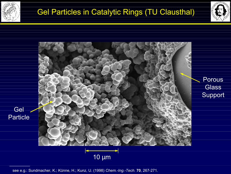
Gel Particles in Catalytic Rings (TU Clausthal)
see e.g.: Sundmacher, K.; Künne, H.; Kunz, U. (1998) Chem.-Ing.-Tech. 70, 267-271.
10 µm
PorousGlass
Support
GelParticle
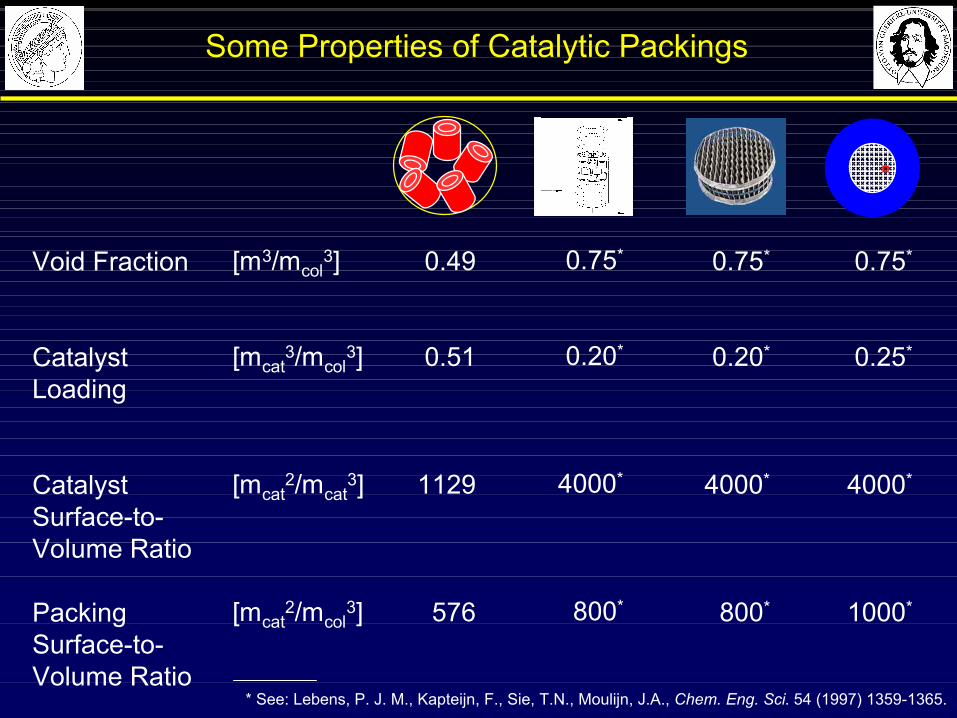
Some Properties of Catalytic Packings
0.49
0.51
1129
576
Void Fraction
Catalyst Loading
Catalyst Surface-to-Volume Ratio
PackingSurface-to-Volume Ratio
0.75*
0.20*
4000*
800*
0.75*
0.20*
4000*
800*
0.75*
0.25*
4000*
1000*
[m3/mcol3]
[mcat3/mcol
3]
[mcat2/mcat
3]
[mcat2/mcol
3]
* See: Lebens, P. J. M., Kapteijn, F., Sie, T.N., Moulijn, J.A., Chem. Eng. Sci. 54 (1997) 1359-1365.
Catalytic Distillation (CD) - Outline
4 Modelling, Simulation,Experimental Validation
CD Expert !
3 Catalysts for Usein CD Processes
2 Fields of Application,Process Examples
5 Operational ProcessBehaviour
1 Basic Principles of CD
Modern Methods in Heterogeneous Catalysis ResearchFritz Haber Institute, Berlin, 14 November 2003
CD Lecture
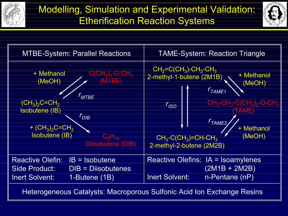
Modelling, Simulation and Experimental Validation:Etherification Reaction Systems
Heterogeneous Catalysts: Macroporous Sulfonic Acid Ion Exchange Resins
Reactive Olefins: IA = Isoamylenes (2M1B + 2M2B)
Inert Solvent: n-Pentane (nP)
Reactive Olefin: IB = IsobuteneSide Product: DIB = DiisobutenesInert Solvent: 1-Butene (1B)
TAME-System: Reaction Triangle
CH2=C(CH3)-CH2-CH32-methyl-1-butene (2M1B)
CH3-C(CH3)=CH-CH32-methyl-2-butene (2M2B)
CH3-CH2-C(CH3)2-O-CH3(TAME)
+ Methanol(MeOH)
+ Methanol(MeOH)
rISO
rTAME1
rTAME2
MTBE-System: Parallel Reactions
C(CH3)3-O-CH3(MTBE)
rMTBE
C8H16Diisobutene (DIB)
rDIB
+ (CH3)2C=CH2Isobutene (IB)
+ Methanol(MeOH)
(CH3)2C=CH2Isobutene (IB)
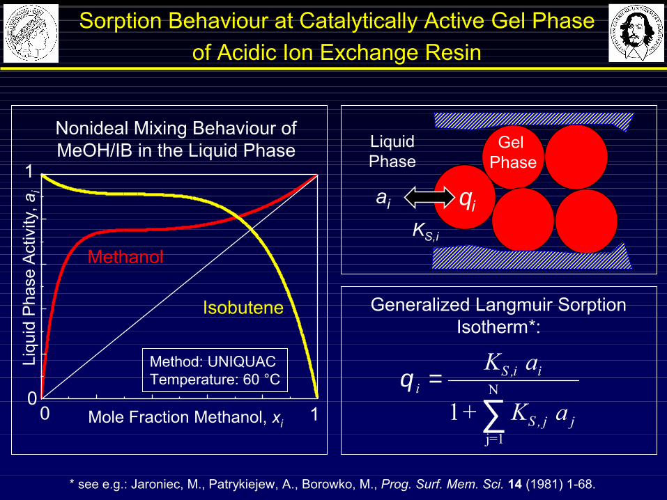
Sorption Behaviour at Catalytically Active Gel Phase of Acidic Ion Exchange Resin
* see e.g.: Jaroniec, M., Patrykiejew, A., Borowko, M., Prog. Surf. Mem. Sci. 14 (1981) 1-68.
Liqu
id P
hase
Act
ivity
, ai
Method: UNIQUACTemperature: 60 °C
Mole Fraction Methanol, xi
010
1
Methanol
Isobutene
Nonideal Mixing Behaviour ofMeOH/IB in the Liquid Phase
Generalized Langmuir SorptionIsotherm*:
θ iS i i
S j j
K a
K a=
∑,
,
1+ j=1
N
LiquidPhase
θiai
KS,i
Gel Phase
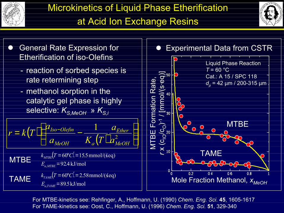
Microkinetics of Liquid Phase Etherificationat Acid Ion Exchange Resins
For MTBE-kinetics see: Rehfinger, A., Hoffmann, U. (1990) Chem. Eng. Sci. 45, 1605-1617For TAME-kinetics see: Oost, C., Hoffmann, U. (1996) Chem. Eng. Sci. 51, 329-340
- reaction of sorbed species israte retermining step
- methanol sorption in thecatalytic gel phase is highly selective: KS,MeOH » KS,i
( ) ( )
−= −
21
MeOH
Ether
aMeOH
OlefinIso
aa
TKaa
Tkr
l Experimental Data from CSTR
Liquid Phase ReactionT = 60 °CCat.: A 15 / SPC 118dp = 42 µm / 200-315 µm
Mole Fraction Methanol, xMeOH
MTB
E F
orm
atio
n R
ate,
rx (c
IO/c
O)-1
/ [m
mol
/(s·e
q)]
l General Rate Expression for Etherification of iso-Olefins
( )kJ/mol 4.92
eq)mmol/(s 5.1560
, =⋅=°=
MTBEa
MTBE
ECTk
.
( )kJ/mol 5.89
eq)mmol/(s 58.260
, =⋅=°=
TAMEa
TAME
ECTk
MTBE
TAME
MTBE
TAME
V LS
Vjxi,j
V
hjV
TjV
Lj-1xi,j-1
L
hj-1L
Tj-1L
Vj+1xi,j+1
V
hj+1V
Tj+1V
Ljxi,j
L
hjL
TjL
QjU
Qreb
Fm
α,β
R
j - 1j
j + 1
p
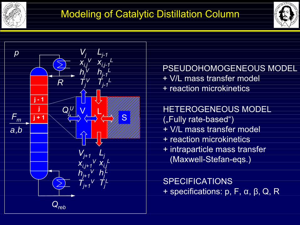
Modeling of Catalytic Distillation Column
PSEUDOHOMOGENEOUS MODEL+ V/L mass transfer model + reaction microkinetics
HETEROGENEOUS MODEL(„Fully rate-based“)+ V/L mass transfer model+ reaction microkinetics+ intraparticle mass transfer
(Maxwell-Stefan-eqs.)
SPECIFICATIONS+ specifications: p, F, α, β, Q, R
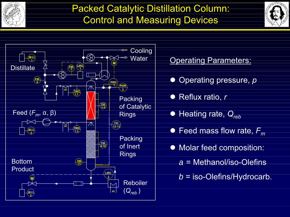
Packed Catalytic Distillation Column:Control and Measuring Devices
Operating Parameters:
l Operating pressure, p
l Reflux ratio, r
l Heating rate, Qreb
l Feed mass flow rate, Fm
l Molar feed composition:
α = Methanol/iso-Olefins
β = iso-Olefins/Hydrocarb.
1el.
el.
1
M
TIR
TIR
TIR
FIR
LIRC
TIRC
2 PIRC
TIRC
6-10
11
PDIR
1-5
1FIR
2
1.1
1.3
TIC12-13
2LIRC
M
W I I
W I I1
3el.
W I I2
CoolingWater
Distillate
Feed (Fm, α, β)
Bottom Product
Reboiler(Qreb )
Packingof Catalytic Rings
Packingof Inert Rings
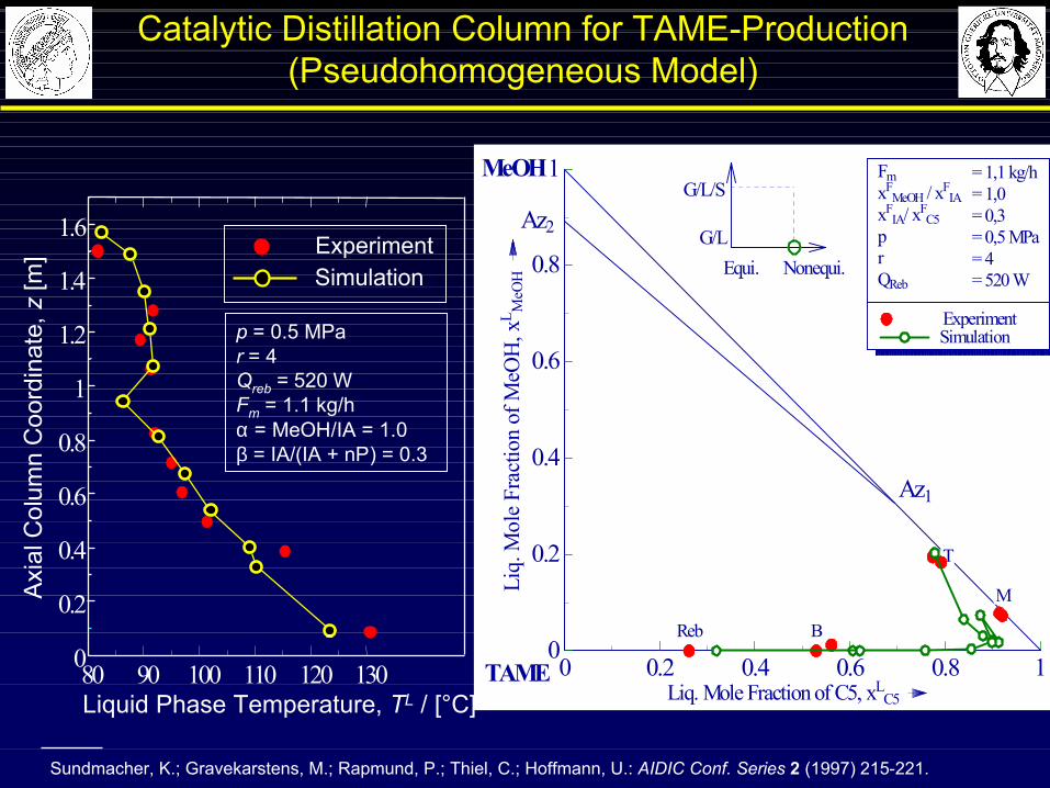
Catalytic Distillation Column for TAME-Production(Pseudohomogeneous Model)
p = 0.5 MPar = 4Qreb = 520 WFm = 1.1 kg/hα = MeOH/IA = 1.0β = IA/(IA + nP) = 0.3
ExperimentSimulation
Axi
al C
olum
n C
oord
inat
e, z
[m]
Liquid Phase Temperature, TL / [°C]80 90 100 110 120 1300
0.2
0.4
0.6
0.8
1
1.2
1.
1.
4
6
Sundmacher, K.; Gravekarstens, M.; Rapmund, P.; Thiel, C.; Hoffmann, U.: AIDIC Conf. Series 2 (1997) 215-221.
Exp. DataSimulation
0 0.2 0.4 0.6 0.8 1Liq. Mole Fraction of C5, xL
C5
0
0.2
0.4
0.6
0.8
1
Liq.
Mol
e Fr
actio
n of
MeO
H, x
L MeO
H
Az2
Az1Az1
Experiment Experiment
TT
MM
BBRebReb
SimulationSimulation
FmxF
MeOH / xFIAxF
MeOH / xFIA
xFIA/ xF
C5xFIA/ xF
C5pprrQRebQReb
= 1,1 kg/h= 1,0= 1,0= 0,3= 0,3= 0,5 MPa= 4= 4= 520 W= 520 WEqui. Nonequi.Equi. Nonequi.
G/L/SG/L/S
G/LG/L
TAME
MeOH

Catalytic Distillation (CD) - Outline
4 Modelling, Simulation,Experimental Validation
CD Expert !
3 Catalysts for Usein CD Processes
2 Fields of Application,Process Examples
5 Operational ProcessBehaviour
1 Basic Principles of CD
Modern Methods in Heterogeneous Catalysis ResearchFritz Haber Institute, Berlin, 14 November 2003
CD Lecture

Influence of Reflux Ratio on Conversion
Bessling, B.; Löning, J.M.; Ohligschläger, A.; Schembecker, G.; Sundmacher, K., Chem Eng. Technol. 21 (5), 393-400.
Conversion of Acetic Acid
Methyl Acetate
Acetic Acid
Water
Catalytic Section (ICVT-Rings)
Rectifying Section (Rombopak 9M)
Stripping Section (Rombopak 9M)
Methanol
Methyl Acetate
Acetic Acid
Water
Catalytic Section (ICVT-Rings)
Rectifying Section (Rombopak 9M)
Stripping Section (Rombopak 9M)
Methanol
There is an optimal reflux ratio !
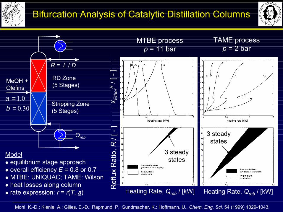
Bifurcation Analysis of Catalytic Distillation Columns
Mohl, K.-D.; Kienle, A.; Gilles, E.-D.; Rapmund, P.; Sundmacher, K.; Hoffmann, U., Chem. Eng. Sci. 54 (1999) 1029-1043.
MTBE processp = 11 bar
TAME processp = 2 bar
Modell equilibrium stage approachl overall efficiency E = 0.8 or 0.7l MTBE: UNIQUAC; TAME: Wilsonl heat losses along columnl rate expression: r = r(T, a)
Ref
lux
Rat
io, R
/ [ -
]x E
ther
B/ [
-]
3 steadystates
Heating Rate, Qreb / [kW] Heating Rate, Qreb / [kW]
R = L / D
RD Zone(5 Stages)
Stripping Zone(5 Stages)
MeOH +Olefins
Qreb
30.00.1
==
βα
3 steadystates
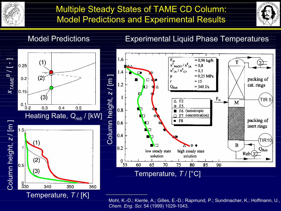
Multiple Steady States of TAME CD Column:Model Predictions and Experimental Results
Mohl, K.-D.; Kienle, A.; Gilles, E.-D.; Rapmund, P.; Sundmacher, K.; Hoffmann, U., Chem. Eng. Sci. 54 (1999) 1029-1043.
Experimental Liquid Phase TemperaturesModel Predictions
Col
umn
heig
ht, z
/ [m
]x T
AM
EB
/ [ -
]
Col
umn
heig
ht, z
/ [m
]
Temperature, T / [°C]
Heating Rate, Qreb / [kW]
Temperature, T / [K]
TIR10
TIR 5
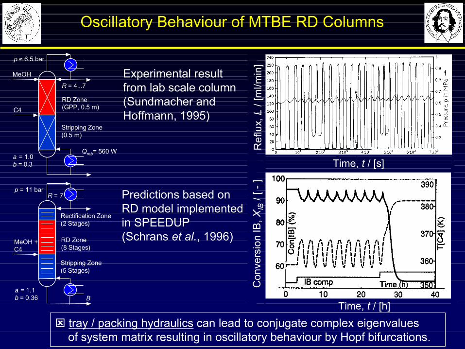
Oscillatory Behaviour of MTBE RD Columns
Predictions based on RD model implementedin SPEEDUP(Schrans et al., 1996)
Experimental result from lab scale column(Sundmacher and Hoffmann, 1995)
ý tray / packing hydraulics can lead to conjugate complex eigenvalues of system matrix resulting in oscillatory behaviour by Hopf bifurcations.
B
R = 7
Rectification Zone (2 Stages)
RD Zone(8 Stages)
Stripping Zone (5 Stages)
MeOH + C4
p = 11 bar
α = 1.1β = 0.36
R = 4...7
RD Zone(GPP, 0.5 m)
Stripping Zone(0.5 m)
MeOH
C4
p ≈ 6.5 bar
Qreb= 560 Wα = 1.0β = 0.3 Time, t / [s]
Ref
lux,
L / [
ml/m
in]
Con
vers
ion
IB, X
IB/ [
-]
Time, t / [h]

Catalytic Distillation (CD)
4 Modelling, Simulation,Expérimental´Validation
CD Expert !
3 Catalysts for Usein CD Processes
2 Fields of Application,Process Examples
5 Operational ProcessBehaviour
1 Basic Principles of CD
CD Lecture
Modern Methods in Heterogeneous Catalysis ResearchFritz Haber Institute, Berlin, 14 November 2003

Many thanks for fruitful scientific co-operation with
§ Prof.-Ing. Achim Kienle, Dipl.-Ing. Erik Stein,
Dr. Zhiwen Qi, Dr. Aspi Kolah (all MPI-Magdeburg)
§ Dipl.-Ing. Klaus-Dieter Mohl (Stuttgart University)
§ Dr.-Ing. Ulrich Kunz, Prof. Dr.-Ing. Ulrich Hoffmann (TU Clausthal)
Many thanks to the FHI organisers for invitation!
Acknowledgements
Modern Methods in Heterogeneous Catalysis ResearchFritz Haber Institute, Berlin, 14 November 2003