cathodic protection on the uk's midland links motorway ... · loughborough university...
TRANSCRIPT
Loughborough UniversityInstitutional Repository
Cathodic protection on theUK's Midland Linksmotorway viaducts
This item was submitted to Loughborough University's Institutional Repositoryby the/an author.
Citation: CHRISTODOULOU, C. .... et al, 2013. Cathodic protection on theUK's Midland Links motorway viaducts. Proceedings of the Institution of CivilEngineers: Bridge Engineering, 167 (1), pp. 43 �53.
Additional Information:
• This article was published in the journal, Proceedings of the ICE - BridgeEngineering: http://www.icevirtuallibrary.com/content/serial/bren Per-mission is granted by ICE Publishing to print one copy for personal use.Any other use of these PDF files is subject to reprint fees.
Metadata Record: https://dspace.lboro.ac.uk/2134/12998
Version: Published
Publisher: c© ICE Publishing
Please cite the published version.

Cathodic protection on the UK’sMidland Links motorway viaducts
&1 Christian Christodoulou CEng, MICEPrincipal Engineer, AECOM Europe, Birmingham, UK
&2 Ali Sharifi BSc, MPhil, FICorr, CSci, MCIHT, MInstNDTTechnical Director, Amey, International Design Hub, Birmingham, UK
&3 Sunil Das CEng, CSci, MSc, FICorr, MIMMMPrincipal Engineer, Amey, International Design Hub, Birmingham, UK
&4 Chris Goodier BEng, PhD, MCIOB, MICT, FHEASenior Lecturer, Loughborough University, School of Civil and BuildingEngineering, Loughborough, UK
1 2 3 4
The Midland Links motorway viaducts (MLMV) are a series of reinforced concrete structures comprising 21 km of
elevated motorway around the outer circumference of Birmingham. Deterioration was identified early in their
serviceable life due to chloride induced corrosion of the steel reinforcement. An electrochemical treatment utilising an
impressed current cathodic protection (ICCP) was successfully trialled in 1987 with the first large-scale commercial
application of the treatment on the network in 1991. Since then it has been the principal corrosion management
strategy for the MLMV, with 740 structures currently protected by ICCP. The aim of this paper is to offer a brief
historical review of the MLMV network, discuss the deterioration mechanisms and review the historical developments
of ICCP together with its overall performance as a corrosion-management method. Recent developments in cathodic
protection technology and secondary beneficial effects of the ICCP previously not recognised are also discussed on
how they can potentially result in significant cost savings for maintenance agencies for this and other similarly
protected structures.
1. Introduction
Structural concrete is exposed to a myriad of environmental
conditions and therefore subject to a wide variety of physical
and chemical deterioration. Of these, chemical deterioration is
very common, and of particular importance is the corrosion of
reinforcement within concrete. Figure 1 illustrates an example
of chloride-induced damage for a steel-reinforced-concrete
structure.
Reinforcement corrosion is an electrochemical process. The two
main causes of corrosion in concrete structures are chloride attack
and concrete carbonation. Concrete, under normal circum-
stances, provides a highly alkaline environment for the reinforce-
ment with pH above 13. Under these conditions, the steel remains
passive owing to formation of an oxide film, which covers its
surface and presents a barrier to further metal dissolution (Glass
and Buenfeld, 1996; Page and Treadaway, 1982).
This paper focuses on the main cause – chloride-induced
corrosion. The presence of chlorides in concrete can be a result
of either bound chlorides cast in the concrete during
construction or ingress of chlorides owing to exposure to a
marine environment (i.e., sea water) or the use of de-icing salts.
The use of calcium chloride as a concrete accelerator has been
restricted since the 1970s (BSI, 1988) and therefore corrosion
problems nowadays are mainly attributable to the external
ingress of chlorides.
Electrochemical principles of corrosion reactions can be
demonstrated with the aid of pH-potential (thermodynamic
properties) and polarisation diagrams (kinetic properties). The
most thermodynamically stable form of iron as a relationship
of the potential and the pH can be illustrated by the simplified
Pourbaix diagram in Figure 2. It can be observed that the
passive oxide film is the most stable product for the conditions
naturally encountered in concrete (pH of 13 or more). For
corrosion to occur, this passive oxide film needs to be broken
down. This will occur above a certain chloride concentration,
otherwise known as the chloride threshold limit (ACI, 2001;
Everett and Treadaway, 1985). A recent study by Angst et al.
Bridge Engineering
Cathodic protection on the UK’s MidlandLinks motorway viaductsChristodoulou, Sharifi, Das and Goodier
Proceedings of the Institution of Civil Engineers
http://dx.doi.org/10.1680/bren.12.00015
Paper 1200015
Received 25/05/2013 Accepted 04/01/2013
Keywords: bridges/concrete structures/corrosion
ice | proceedings ICE Publishing: All rights reserved
1

(2009) illustrated that there is a very broad range of reported
values of chloride threshold limits, from 0?1% chloride to in
excess of 2% chloride (by weight of cement), indicating that
corrosion initiation is subject to a number of factors, not just
chloride concentration (Glass and Buenfeld, 1997; Glass et al.,
2000; Sergi and Glass, 2000).
2. The viaducts
By 1957 it was becoming apparent in the UK that a transport
link was needed between the M1, M5 and M6. The detailed
studies that followed resulted in what is nowadays known as
the Midland Links. It comprised in total 106 km of motorway
of which 69 km were rural type and 37 km urban type
motorway. Out of these, 21?3 km consisted of motorway
viaducts or as commonly known the Midland Links motor-
way viaducts (MLMV). The section between Gravelly Hill
and Castle Bromwich (junctions 6 to 5 of the M6) was the
longest continuous viaduct in the MLMV at a total length of
5?6 km. Part of the MLMV is the Gravelly Hill interchange,
junction 6 of the M6, commonly known as the ‘Spaghetti
Junction’ owing to its complexity and was the first of its kind.
It connects the M6 with the A38M motorway, A38 and the
A5127 (Figure 3).
The MLMV had to pass through a number of urban and rural
areas and as a result there was a variety of natural and man-
made obstructions to overcome. These obstructions included
several canals, the River Tame, River Rea, several reservoirs,
the Birmingham–Peterborough train line, the Chase (also
known as Walsall) train line, other cross-city train lines, 18 in
(0?46 m) diameter high-pressure gas mains, 440 kV overhead
electricity lines and many others. Where possible a standard
arrangement of a 15?24 m (50 ft) span was adopted with simply
supported steel beams and reinforced-concrete composite deck
slabs, supported on reinforced-concrete crossbeams, in turn
supported on reinforced-concrete columns (Figure 4). Across
the entire MLMV there are over 1300 spans, crossbeams and
expansion joints and more than 3600 columns.
There were occasions however, where this typical arrangement
could not be adopted owing to access issues posed by the
Figure 1. Typical chloride-induced corrosion damage to a
reinforced-concrete structure
200O2
0
–200 Passive
Fe2O3
Fe3O4
–400 Corrosion
–600Fe2+
Fe3+
Fe
–1000
–800Immune
pH862 4 1410 12
Pot
entia
l: m
V (a
gain
st s
tand
ard
calo
mel
ele
ctro
de)
Figure 2. Modified Pourbaix diagram showing the stability of iron
as a function of pH and potential (Pourbaix, 1990)
Figure 3. Aerial photograph of Gravelly Hill interchange on the
MLMV, J6 of the M6 – known as ‘Spaghetti Junction’
Bridge Engineering Cathodic protection on the UK’sMidland Links motorwayviaductsChristodoulou, Sharifi, Das and
Goodier
2

aforementioned natural and man-made obstructions. Several
alternative solutions were therefore adopted such as
& varying depth I-beams
& steel crossbeams
& longitudinal steel box beams
& continuous deck structures.
Over the years however, the MLMV have suffered from
structural deterioration, primarily corrosion of the reinforce-
ment owing to chloride attack. The chlorides can be traced
back to the de-icing salts used during winter maintenance to
keep the motorways open. The chloride contamination of the
substructure can also be attributed to the leakage that occurred
through the original expansion joints but also through
subsequent expansion joints once they were damaged.
Damaged expansion joints allowed water to fall onto the
reinforced-concrete crossbeams; concrete delamination has
mainly occurred on the top faces but also the elevations of
the crossbeams.
Several different actions were taken in order to implement
corrosion management on the structures. These included installing
gutters, increasing the inspection and testing regimes, using urea as
an alternative de-icing agent to normal road salts, structural
assessments, hydrophobic treatments such as silanes, concrete
repairs and cathodic protection. The use of cathodic protection to
arrest active corrosion and lower the risk of further concrete
deterioration owing to chloride-induced corrosion became more
widespread over the last 25 years and the experiences from its use
are discussed below (Cropper et al., 1998).
3. Cathodic protection
The first electrochemical treatments of reinforced concrete
elements date back to 1959 when the California Department of
Transport (Caltrans) experimented with the first impressed
current cathodic protection (ICCP) system (Stratfull, 1959).
The first known full-scale ICCP system to be installed on a
reinforced concrete bridge was on the Sky Park bridge in
Placerville, California in 1972 (Stratfull, 1973).
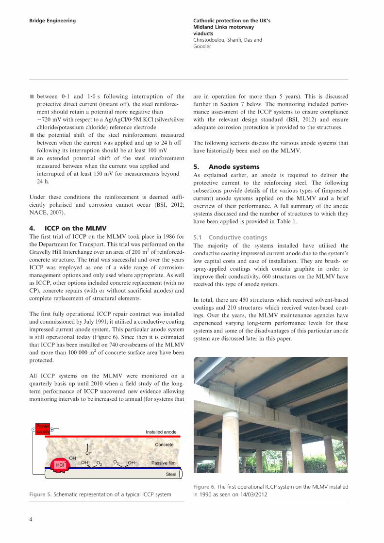
The principle of ICCP is based on the passage of an electric
current from a conductive material (anode) installed either on the
surface, or embedded within the concrete, through an electrolyte
(concrete) to the steel reinforcement (cathode) which opposes the
electric current produced by the corrosion reactions. To achieve
an electrical circuit a power source is required where the anode is
connected to the positive terminal, the steel is connected to the
negative terminal and anode and cathode are separated by an
electrolyte, which in this case will be the concrete. Figure 5
illustrates a schematic representation of a typical ICCP system.
By applying a sufficient magnitude of constant direct current
the steel is polarised and is made cathodic – that is, only
cathodic reaction occurs on the steel reinforcement – hence, the
term cathodic protection (Broomfield, 2007; Christodoulou
et al., 2009). For atmospherically exposed reinforced concrete
the requirements for adequate protection relate to
Expansion joint A
Section A–AA
Hardshoulder Carriageway – 3 lanes
Reinforced-concretedeck slab
Steelbeams
Reinforced-concretecolumns
Reinforced-concreteshear walls
Reinforced-concretecrossbeam
Figure 4. Schematic representation of a typical MLMV structural
arrangement
Bridge Engineering Cathodic protection on the UK’sMidland Links motorwayviaductsChristodoulou, Sharifi, Das and
Goodier
3
& between 0?1 and 1?0 s following interruption of the
protective direct current (instant off), the steel reinforce-
ment should retain a potential more negative than
2720 mV with respect to a Ag/AgCl/0?5M KCl (silver/silver
chloride/potassium chloride) reference electrode
& the potential shift of the steel reinforcement measured
between when the current was applied and up to 24 h off
following its interruption should be at least 100 mV
& an extended potential shift of the steel reinforcement
measured between when the current was applied and
interrupted of at least 150 mV for measurements beyond
24 h.
Under these conditions the reinforcement is deemed suffi-
ciently polarised and corrosion cannot occur (BSI, 2012;
NACE, 2007).
4. ICCP on the MLMVThe first trial of ICCP on the MLMV took place in 1986 for
the Department for Transport. This trial was performed on the
Gravelly Hill Interchange over an area of 200 m2 of reinforced-
concrete structure. The trial was successful and over the years
ICCP was employed as one of a wide range of corrosion-
management options and only used where appropriate. As well
as ICCP, other options included concrete replacement (with no
CP), concrete repairs (with or without sacrificial anodes) and
complete replacement of structural elements.
The first fully operational ICCP repair contract was installed
and commissioned by July 1991; it utilised a conductive coating
impressed current anode system. This particular anode system
is still operational today (Figure 6). Since then it is estimated
that ICCP has been installed on 740 crossbeams of the MLMV
and more than 100 000 m2 of concrete surface area have been
protected.
All ICCP systems on the MLMV were monitored on a
quarterly basis up until 2010 when a field study of the long-
term performance of ICCP uncovered new evidence allowing
monitoring intervals to be increased to annual (for systems that
are in operation for more than 5 years). This is discussed
further in Section 7 below. The monitoring included perfor-
mance assessment of the ICCP systems to ensure compliance
with the relevant design standard (BSI, 2012) and ensure
adequate corrosion protection is provided to the structures.
The following sections discuss the various anode systems that
have historically been used on the MLMV.
5. Anode systemsAs explained earlier, an anode is required to deliver the
protective current to the reinforcing steel. The following
subsections provide details of the various types of (impressed
current) anode systems applied on the MLMV and a brief
overview of their performance. A full summary of the anode
systems discussed and the number of structures to which they
have been applied is provided in Table 1.
5.1 Conductive coatings
The majority of the systems installed have utilised the
conductive coating impressed current anode due to the system’s
low capital costs and ease of installation. They are brush- or
spray-applied coatings which contain graphite in order to
improve their conductivity. 660 structures on the MLMV have
received this type of anode system.
In total, there are 450 structures which received solvent-based
coatings and 210 structures which received water-based coat-
ings. Over the years, the MLMV maintenance agencies have
experienced varying long-term performance levels for these
systems and some of the disadvantages of this particular anode
system are discussed later in this paper.
Concrete
- + Installed anode
Cl–OH–
Steel
Passive filmOH– OH–
Powersupply
O2O2HCl
Figure 5. Schematic representation of a typical ICCP system
Figure 6. The first operational ICCP system on the MLMV installed
in 1990 as seen on 14/03/2012
Bridge Engineering Cathodic protection on the UK’sMidland Links motorwayviaductsChristodoulou, Sharifi, Das and
Goodier
4
The conductive coatings are in general considered to provide
adequate corrosion protection but the current densities
delivered are usually limited to 20 mA/m2 of concrete surface
area. With the steel reinforcement to concrete surface ratio
exceeding 2 at certain critical locations this equates to a
maximum protective current density of 10 mA/m2 of steel
surface area. For cathodic protection design it is recommended
to use current density values ranging 5 mA/m2 to 20 mA/m2 of
steel surface area (BSI, 2012).
As a general rule, ICCP systems are usually commissioned at a
quarter of their maximum capacity, and their performance is
assessed based on the criteria of BS EN ISO 12696 (BSI, 2012),
discussed previously. Such an approach is usually sufficient to
meet the performance requirements of the standards. Although
the design standards recommend higher current densities than
the ones usually used to commission conductive coating anode
systems, this approach has not caused any issues and the
systems met their performance criteria at all times during
commissioning. Over the last 25 years, the annual performance
monitoring for every structure protected by ICCP has
indicated that conductive coatings have been performing
satisfactorily and within the requirements of the design
standards. It appears that conductive coatings have been
providing the necessary current to protect the substructures on
the MLMV, suggesting that potentially lower protective design
current densities may be appropriate.
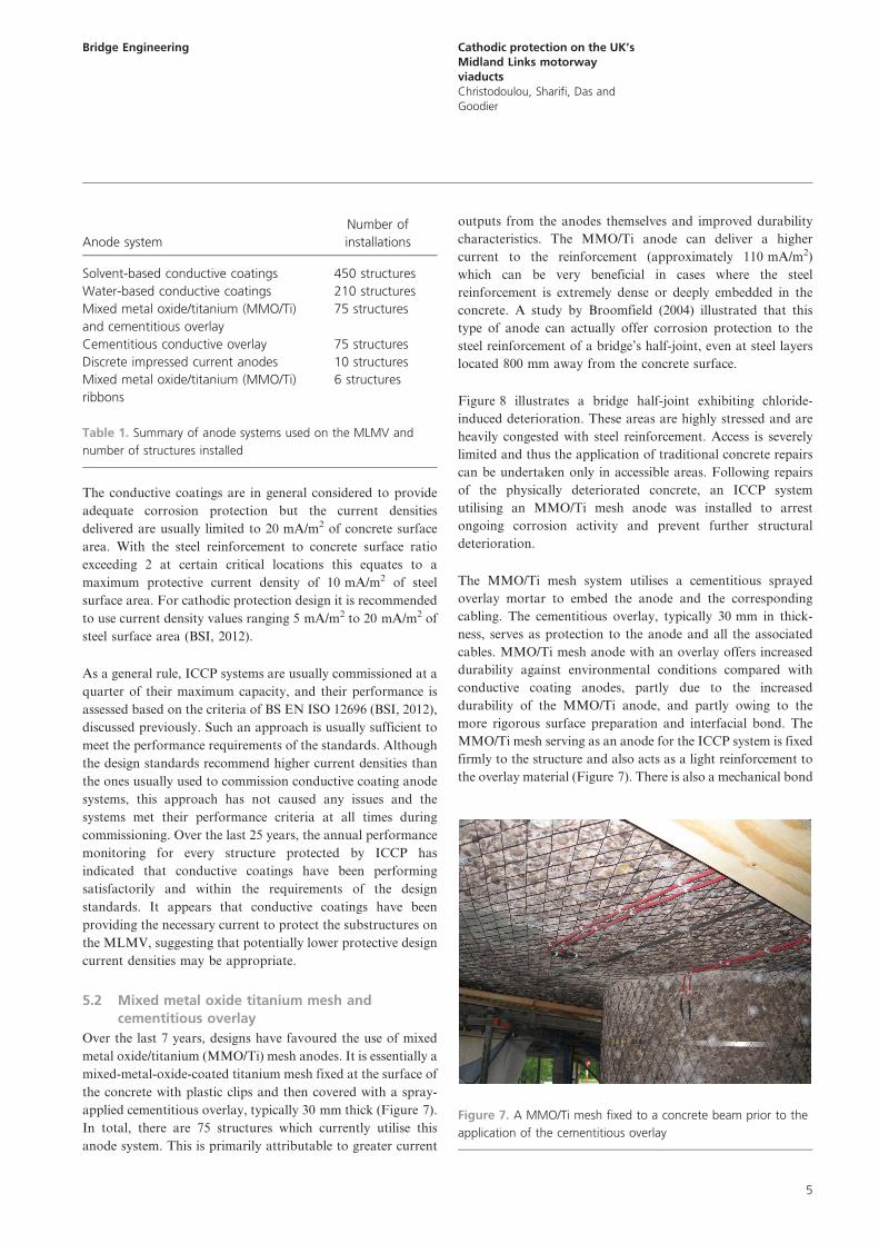
5.2 Mixed metal oxide titanium mesh and
cementitious overlay
Over the last 7 years, designs have favoured the use of mixed
metal oxide/titanium (MMO/Ti) mesh anodes. It is essentially a
mixed-metal-oxide-coated titanium mesh fixed at the surface of
the concrete with plastic clips and then covered with a spray-
applied cementitious overlay, typically 30 mm thick (Figure 7).
In total, there are 75 structures which currently utilise this
anode system. This is primarily attributable to greater current
outputs from the anodes themselves and improved durability
characteristics. The MMO/Ti anode can deliver a higher
current to the reinforcement (approximately 110 mA/m2)
which can be very beneficial in cases where the steel
reinforcement is extremely dense or deeply embedded in the
concrete. A study by Broomfield (2004) illustrated that this
type of anode can actually offer corrosion protection to the
steel reinforcement of a bridge’s half-joint, even at steel layers
located 800 mm away from the concrete surface.
Figure 8 illustrates a bridge half-joint exhibiting chloride-
induced deterioration. These areas are highly stressed and are
heavily congested with steel reinforcement. Access is severely
limited and thus the application of traditional concrete repairs
can be undertaken only in accessible areas. Following repairs
of the physically deteriorated concrete, an ICCP system
utilising an MMO/Ti mesh anode was installed to arrest
ongoing corrosion activity and prevent further structural
deterioration.
The MMO/Ti mesh system utilises a cementitious sprayed
overlay mortar to embed the anode and the corresponding
cabling. The cementitious overlay, typically 30 mm in thick-
ness, serves as protection to the anode and all the associated
cables. MMO/Ti mesh anode with an overlay offers increased
durability against environmental conditions compared with
conductive coating anodes, partly due to the increased
durability of the MMO/Ti anode, and partly owing to the
more rigorous surface preparation and interfacial bond. The
MMO/Ti mesh serving as an anode for the ICCP system is fixed
firmly to the structure and also acts as a light reinforcement to
the overlay material (Figure 7). There is also a mechanical bond
Anode system
Number of
installations
Solvent-based conductive coatings 450 structures
Water-based conductive coatings 210 structures
Mixed metal oxide/titanium (MMO/Ti)
and cementitious overlay
75 structures
Cementitious conductive overlay 75 structures
Discrete impressed current anodes 10 structures
Mixed metal oxide/titanium (MMO/Ti)
ribbons
6 structures
Table 1. Summary of anode systems used on the MLMV and
number of structures installed
Figure 7. A MMO/Ti mesh fixed to a concrete beam prior to the
application of the cementitious overlay
Bridge Engineering Cathodic protection on the UK’sMidland Links motorwayviaductsChristodoulou, Sharifi, Das and
Goodier
5

of the cementitious overlay with the mesh in addition to the
chemical bond between the parent concrete and the overlay.
Although the initial capital costs for this type of anode are
higher, as opposed to conductive coating and conductive
overlays (see below), over the whole life cycle of the ICCP
system the anode does not need to be replaced as it is fully
encapsulated and thus protected from environmental effects. In
the long term, this approach can provide a very cost-effective
solution.
5.3 Cementitious conductive overlays
This type of anode comprises a cementitious material with
conductive fibres to provide electrical conductivity. It is spray
applied and also contains a strip (ribbon) of MMO/Ti as the
primary current feeder to the overlay. The current is then
evenly distributed through the overlay as a result of the
conductive fibres.
The structures did not originally have bearing stiffeners and
transverse restraint was provided by thin and wide reinforced-
concrete shear walls (Figure 4). These shear walls were cast
integrally with the reinforced-concrete crossbeams and hinged
to the reinforced-concrete deck slab above.
These shear walls also received the conductive coating anode
system. However, the introduction of the MMO/Ti mesh
anodes with a cementitious overlay for the crossbeams was not
considered appropriate for shear walls on the MLMV owing to
their flexural movement which could cause considerable
cracking of the thick overlay material.
Continuing the application of the conductive coatings to the
shear walls was also a possibility but an alternative design
solution was required which would improve the durability in a
similar way as for the crossbeams. In this case spray-applied
cementitious conductive overlays formulated to offer electrical
conductivity in a similar way to the conductive coatings were
used. Electrical current is delivered to the overlay by an MMO/
Ti ribbon which can be embedded within the overlay. With
regards to the output current densities, conductive overlays
provide similar outputs to conductive coating anodes (max-
imum of 20 mA/m2 of concrete surface area).
The advantage of this conductive overlay anode system is
derived from its increased flexural strength as a result of the
added fibres which improve control of structural micro-
cracking owing to vibrations. In addition, the thickness of
the system (up to 8 mm) is considerably less when compared to
the thickness required for the cementitious overlays accom-
panying the MMO/Ti anodes.
Spray-applied conductive coatings are a recent development on
the MLMV, applied to help provide cathodic protection to the
shear walls after the introduction of an ICCP system using
mesh and overlay less than 10 years ago. To date, no issues
have been reported with the long-term performance of these
conductive overlays.
5.4 Discrete impressed current anodes
These anodes are usually cylindrically shaped tubes inserted
into pre-made cavities within the reinforced-concrete structure
and connected together to form an array of anodes acting in
unison over a specific area. The number of anodes installed is
varying depending on the steel density, with higher amounts of
steel requiring a greater amount of anodes.
In the MLMV, discrete anodes have been used on a limited
number of MLMV structures, mainly utilised in cases where
access for installation is extremely restricted. Typically, they
have been used for additional protection of the intermediate
layers of reinforcement on half-joints and also for protecting
the reinforcement in the bearing plinths. To date, where
discrete anodes have been employed they are usually together
with other anode systems such as MMO/Ti mesh and overlay.
Installation of discrete anodes to protect very large concrete
surfaces with high amounts of steel reinforcement can be a
tedious, time-consuming and could be an expensive approach.
This is attributable to the fact that very large numbers of
anodes are required to be installed in pre-drilled holes together
with associated wiring to connect those anodes to the power
supply. In view of this, surface-mounted anodes could become
more cost-effective and easier to install.
Very importantly, the anodes should have no physical contact
with the steel reinforcement in order to ensure that they
are electrically isolated. Otherwise, the anodes will form a
Figure 8. Chloride induced corrosion deterioration of a bridge half-
joint
Bridge Engineering Cathodic protection on the UK’sMidland Links motorwayviaductsChristodoulou, Sharifi, Das and
Goodier
6

short-circuit with the reinforcement and no corrosion protec-
tion will exist.
Discrete anodes tend to offer high design current densities and
are usually installed in areas of high corrosion risk which have
difficult accessibility. Thus, the anodes are usually operated on
high current densities not far from their capacity as opposed to
an MMO/Ti mesh anode and overlay.
5.5 Mixed metal oxide/titanium (MMO/Ti) ribbons
More recently MMO/Ti ribbon anodes installed in concrete
chases or embedded within a cementitious overlay have also
been used on six MLMV structures. As discussed previously,
MMO/Ti ribbon anodes installed on the surface of shear walls
and then covered with a conductive overlay has successfully
been used. Extending the use of these types of anodes on other
parts of structures was therefore considered feasible and
anodes were subsequently installed on the crossbeams, column
tops and abutment walls.
The ribbons are in principle a type of very condensed and
tightly arranged strip of mesh coated with a MMO. Ribbons
offer the same advantages as MMO/Ti mesh with high current
densities and ease of installation. Where ribbons are installed
in concrete chases, they do not require large amounts of
cementitious overlays as they are installed in cavities and
covered by a grout. Nonetheless, there is still a need for good
accessibility in order to saw-cut the chases and achieving good
cover to the ribbon anodes is critical for the durability of the
cathodic protection system.
In the MLMV ribbons have just started to be applied and
therefore their track record is not long. They have been used in
areas such as the bearing shelf where availability of space is
very limited for the installation of a MMO/Ti mesh and the
concrete top is heavily congested with reinforcement, which
makes the installation of discrete anodes very difficult. They
have also been applied within a cementitious overlay to protect
crossbeams and column tops.
Overall, all the anode systems utilised have slowed ongoing
corrosion activity and reduced risk of future corrosion damage.
This was also illustrated by a recent study which is examined
later. ICCP is a technique capable of extending the service life
of chloride contaminated concrete structures without the
necessity to remove contaminated but otherwise sound
concrete.
6. DisadvantagesAlthough the application of ICCP has been very successful on
the MLMV with several hundred reinforced-concrete struc-
tures already protected, there have also been a number of
issues. Figure 9 illustrates an example of an ICCP system
(utilising a conductive coating) exhibiting signs of severe anode
deterioration which subsequently resulted in the loss of the
protective current.
Deterioration of the conductive coatings may be attributed
to a number of reasons. Good surface preparation is very
important in ensuring durability as it can affect the bond
strength between the parent concrete and the coating. The
prevalent environmental conditions such as sunlight and rain
can seriously affect the durability of the conductive coatings.
Long-term exposure to cycling drying and wetting is a major
issue for durability and it has been observed that the
majority of the anode deterioration has occurred on the
more exposed areas of the structures as a result of loss of
bond between the concrete and the conductive coating
anode. In addition, these conductive anode coatings have
been supplied by a number of manufacturers and their
performance has been variable. It should be noted that these
anodes were initially envisaged to have 10 years design life
which in all cases have been met.
Only conductive coating anodes have suffered in this way and
no evidence currently exist with regards to anode deterioration
for the conductive cementitious overlays and the MMO/Ti
anodes with a cementitious overlay.
Electrical shorts can also affect the operation of the ICCP
system. When the anode is in direct physical contact with the
reinforcement or tie wires which are attached to the reinforce-
ment then the electrical circuit is shorted and no protective
current is being passed. Such occurrences have tended to be
Concrete surface
Delaminatingconductivecoating anode
Figure 9. An original water-based conductive coating ICCP system
from a section of the M5 motorway, installed in 1993 showing
severe delamination of the conductive coating
Bridge Engineering Cathodic protection on the UK’sMidland Links motorwayviaductsChristodoulou, Sharifi, Das and
Goodier
7
rare and quickly repaired as there is a very rigorous quality
assurance (QA) regime applied on the MLMV at the time of
the installation of the CP systems.
A vital element of each ICCP system is the power supply.
Initially, these were located at ground level to enable good
access, with the cables rising to the crossbeams by way of cable
trays attached to the columns of the structures. However,
vandalism of the electrical cabling is becoming more common
and results to a loss of the protective current to the structures.
Several structures have been affected from vandalism and
required expensive repairs to replace the electrical wiring and
the power supplies. Power supplies, cabling and monitoring
equipment now tends to be installed at high level to reduce the
risk of vandalism.
For the older ICCP systems, one power supply provided the
required protection to each structure. For this reason they were
classified as single zone systems. However, over the last decade
multi-zone systems have been favoured with a number of
power supplies protecting different parts of each structure.
Although this approach offers better control of the operating
system, it has also resulted in higher capital costs owing to the
greater number of power supplies now required and the
increase in monitoring locations (as each zone needs to be
monitored for its individual performance).
7. Recent developments and discussionICCP has generally been associated with high initial capital
costs and recently its cost effectiveness has been questioned. A
recently completed study by some of the authors investigated
the long-term benefits of the early conductive coating anode
systems with a view to improving the design approach, reduce
maintenance requirements and ultimately reduce initial capital
costs (Christodoulou et al., 2010, 2012). This study examined a
number of conductive coating anode systems for their long-
term performance, including systems which were until today
operational and others which where exhibiting significant
anode deterioration and as such loss of protective current.
The study interrupted the protective current to ten structures
for a period of 3 years and monitored on a monthly basis the
condition of the steel reinforcement at critical locations for the
initiation of corrosion. The age of the ICCP systems that were
selected for this study ranged from 17 years for the oldest to 6
years for the youngest, at the time of the interruption in 2008.
The corrosion condition of the reinforcement was assessed by
non-destructive electrochemical measurements including steel
potentials and corrosion rate measurements (Christodoulou
et al., 2012).
Measuring steel potentials against the potential of a standard
reference electrode is a long-established technique (Elsener,
2003; Stratfull, 1957). The observed steel potentials can then
be assessed against published values and an estimate can be
made on the corrosion risk and corrosion probability. In
accordance with BA 35/90 (BSI, 1990) and Concrete Society
Technical Report 60 (Concrete Society, 2004) values more
positive than 2200 mV Cu/CuSO4 (saturated copper/copper
sulfate) reference electrode indicate a low probability of
corrosion. Overall, steel potentials can give a good approx-
imation of the corrosion risk of steel but they are affected by
various other factors such as temperature, humidity and
oxygen availability.
Corrosion rates are usually expressed as a current density, a
rate of weight loss or a rate of section loss. A corrosion rate of
1 mA/m2, when expressed as a current density, is approxi-
mately equal to a steel weight loss of 10 g/m2/year or a steel
section loss of 1 mm/year (Concrete Society, 2004). In general,
corrosion rates less than 6 mm/year are considered to be low to
moderate (Concrete Society, 2004). Therefore, monitoring is
required to ensure that they do not increase to much higher
values. Corrosion rate measurement can be undertaken on site
with various types of proprietary equipment based on the
polarisation resistance technique.
For the study, the critical locations for each structure were
selected following chloride analysis at the depth of the
reinforcement. The locations of testing were in original un-
repaired concrete which was now protected by an ICCP
system. In the majority of the test locations, chloride
concentration at the depth of the reinforcement exceeded
0?4% by weight of cement – a level at which there is a 50%
probability of corrosion initiation (Concrete Society, 2004). In
fact, several locations even exceeded chloride concentrations of
1?0% by weight of cement – a level at which there is a 95%
probability of corrosion initiation. Such locations posed a high
residual corrosion risk following the interruption of the
protective current provided by the ICCP system.
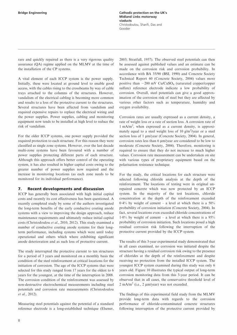
The results of this 3-year experimental study demonstrated that
in all cases examined, no corrosion was initiated despite the
structure having a residual corrosion risk owing to the presence
of chlorides at the depth of the reinforcement and despite
receiving no protection from the installed ICCP system. The
youngest ICCP system examined during this study was only 6
years old. Figure 10 illustrates the typical output of long-term
corrosion monitoring data from this 3-year period. It can be
observed that in all cases, the conservative threshold level of
2 mA/m2 (i.e., 2 mm/year) was not exceeded.
The findings of this experimental field study from the MLMV
provide long-term data with regards to the corrosion
performance of chloride-contaminated concrete structures
following interruption of the protective current provided by
Bridge Engineering Cathodic protection on the UK’sMidland Links motorwayviaductsChristodoulou, Sharifi, Das and
Goodier
8

the ICCP system. These results confirm previously published
data and hypotheses by Broomfield and Tinnea (1992),
Presuel-Moreno et al. (2002) and Polder et al. (2009), that
long-term application of ICCP renders the steel passive and
has a persistent protective effect.
The results illustrate that ICCP is not only providing
protection by means of a potential shift, as required by the
relevant European and international standards (BSI, 2012;
NACE, 2007), but there are other secondary beneficial
protective effects which were probably responsible for the
observed passivity and non-corroding condition of the steel
reinforcement at these ten reinforced-concrete crossbeams
from the MLMV.
Based on these findings the maintenance requirements of
ICCP systems older than 6 years can be reduced, alternative
anode systems can be used and the design requirements for
high levels of protective current to ensure adequate protection
can also be reduced. These findings can result in significant
maintenance and initial capital investment savings for
maintenance agencies.
On the MLMV, the findings of this study have provided the
scientific evidence to reduce the monitoring intervals of all the
ICCP systems older than 6 years from quarterly to annually. In
addition, the results help to prioritise the repair, refurbishment
or replacement of the ICCP systems which have reached the
end of their design life, are affected by vandalism or are
affected by durability issues such as anode de-bonding.
Overall, the performance monitoring of all the ICCP systems
over the past 25 years has illustrated that the ICCP has been
providing continuous corrosion protection to these structures,
has extended their service life by preventing further concrete
and steel deterioration, and have reduced the maintenance
requirements for the asset owner.
8. Conclusions
& ICCP has been one of the many corrosion management
strategies on the MLMV over the past 25 years and was
only used for the structures in most need. ICCP ensured
that for these structures, their ongoing corrosion activity
was arrested and extended their service life.
& Durability of the ICCP systems has been variable, depend-
ing mainly on the type of anode system employed and the
environmental exposure conditions. In particular, conduc-
tive coating anodes have been occasionally affected by poor
bonding with the parent concrete surface, with subsequent
de-bonding of the anode. Additionally, vandalism of the
power supplies and the cabling/equipment has also affected
2.00
1.80
1.60
1.40
1.20
1.00
0.80
Cor
rosi
on ra
te: m
A/m
2
0.60
0.40
0.20
0.00Oct-07 Dec-07 Feb-08 Apr-08 Jun-08 Dec-08 Feb-09 Apr-09 Jun-09Aug-08 Oct-08
Time: dateAug-09 Oct-09
Threshold
Structure
A1
A2
A3
B1
B2
B3
C1
B4
C2
C3
Figure 10. Corrosion rate monitoring of structures in the Midland
Links motorway viaducts following interruption of the protective
current
Bridge Engineering Cathodic protection on the UK’sMidland Links motorwayviaductsChristodoulou, Sharifi, Das and
Goodier
9
the durability of some of the ICCP systems. Improvements
in recent designs have significantly reduced the impacts of
these issues.
& Research on ICCP on the MLMV has also identified
secondary beneficial effects that were previously not
recognised. The long-term application of ICCP has
provided secondary beneficial protective effects, even when
the protective current was interrupted for 3 years; with
consequent potential for significant cost savings for
maintenance agencies. The results have readily been used on
the MLMV to reduce maintenance costs associated with
long-term monitoring and also help to prioritise future
repair and replacement of the ICCP systems.
REFERENCES
ACI (American Concrete Institute) (2001) 222R-01: Corrosion
of Metals in Concrete. Committee 222, ACI, Farmington
Hills, MI, USA.
Angst U, Elsener B, Larsen CK and Vennesland O (2009) Critical
chloride content in reinforced concrete – a review. Cement
and Concrete Research 39: 1112–1138. See http://dx.doi.
org/10.1016/j.cemconres.2009.08.006 (accessed 29/05/
2013).
Broomfield J (2004) A case history of cathodic protection of a
highway structure in the UK. Proceedings of Corrosion
2004. Annual Conference and Exhibition, New Orleans, LA,
USA, paper 04344.
Broomfield J (2007) Corrosion of Steel in Concrete:
Understanding, Investigation and Repair, 2nd edn. Taylor &
Francis, Abingdon, UK.
Broomfield J and Tinnea JS (1992) Cathodic Protection of
Reinforced Concrete Bridge Components, Final Report.
Strategic Highway Research Program, National Academy
of Sciences, Washington, DC, USA, ID no.:
SHRPCUWP92618.
BSI (1988) BS 1881-124:1988: Testing concrete. Methods for
analysis of hardened concrete. BSI, London, UK.
BSI (1990) BA 35/90: Inspection and repair of concrete highway
structures. BSI, London, UK.
BSI (2012) BS EN ISO: 12696-2012: Cathodic protection of
steel in concrete. BSI, London, UK.
Christodoulou C, Glass G, Webb J, Austin SA and Goodier CI (2010)
Assessing the long term benefits of impressed current
cathodic protection. Corrosion Science 52(8): 2671–2679. See
http://dx.doi.org/10.1016/j.corsci.2010.04.018 (accessed 30/
05/2013).
Christodoulou C, Goodier CI, Austin SA, Webb J and Glass G
(2012) On-site transient analysis for the corrosion
assessment of reinforced concrete. Corrosion Science 62:
176–183. See http://dx.doi.org/10.1016/j.corsci.2012.05.014
(accessed 30/05/2013).
Christodoulou C, Glass G and Webb J (2009) Corrosion
management of concrete structures. The Structural
Engineer 87(23/24): 20–22.
Concrete Society (2004) Technical Report 60, Electrochemical
Tests for Reinforcement Corrosion. The Concrete Society,
Croydon, Camberley, Surrey, UK.
Cropper D, Jones A and Roberts MB (1998) A risk-based
maintenance strategy for Midland Links motorway
viaducts, seminar. In Management of Highway Structures.
(Das PC (ed.)). ICE, London, UK, pp. 81–89.
Elsener B (2003) Half cell potential measurements – potential
mapping on reinforced concrete structures, RILEM TC
154-EMC: electrochemical techniques for measuring
metallic corrosion, Materials and Structures 36(7): 461–
471.
Everett LH and Treadaway KWJ (1980) Deterioration due to
corrosion in reinforced concrete. Corrosion Prevention and
Control. BRE, Watford, UK, BRE Information Paper 12/
80.
Glass GK and Buenfeld NR (1996) Reinforced concrete – its
principles of deterioration and repair. In Modern Matters –
Principles and Practice in Conserving Recent Architecture
(Macdonald S (ed.)). Donhead Publishing, Shaftesbury,
UK, pp. 101–112.
Glass GK and Buenfeld NR (1997) The presentation of the
chloride threshold level for corrosion of steel in
concrete. Corrosion Science 39(5): 1001–1013. See http://dx.
doi.org/10.1016/S0010-938X(97)00009-7 (accessed 30/02/
2013).
Glass GK, Ready B and Buenfeld NR (2000) Corrosion
inhibition in concrete arising from its acid neutralisation
capacity, Corrosion Science 42(9): 1587–1598. See http://dx.
doi.org/10.1016/S0010-938X(00)00008-1 (accessed 30/05/
2013).
NACE (2007) SP0290-2007, Item No. 21043, Standard Practice.
Impressed Current Cathodic Protection of Reinforcing
Steel in Atmospherically Exposed Structures. NACE,
Houston, TX, USA.
Page CL and Treadaway KWJ (1982) Aspects of the
electrochemistry of steel in concrete. Nature 297(5862):
109–115.
Polder R, Peelen WHA, Stoop BTJ and Neeft EAC (2009) Early
Stage Beneficial Effects of Cathodic Protection in Concrete
Structures. Eurocorr, Nice, France.
Pourbaix M (1990) Thermodynamics and corrosion. Corrosion
Science 30(10): 963–988.
Presuel-Moreno FJ, Sagues AA and Kranc SC (2002) Steel activation
in concrete following interruption of long-term cathodic
polarisation. Proceedings of Corrosion 2002 Annual Conference
and Exhibition, Denver, CO, USA.
Sergi G and Glass GK (2000) A method of ranking the aggressive
nature of chloride contaminated concrete. Corrosion
Science 42(12): 2043–2049. See http://dx.doi.org/10.1016/
S0010-938X(00)00050-0 (accessed 30/05/2013).
Bridge Engineering Cathodic protection on the UK’sMidland Links motorwayviaductsChristodoulou, Sharifi, Das and
Goodier
10

Stratfull RF (1957) The corrosion of steel in a reinforced
concrete bridge. Corrosion 13(3): 173–178.
Stratfull RF (1959) Progress report on inhibiting the corrosion
of steel in a reinforced concrete bridge. Corrosion 15(6):
331–334.
Stratful RF (1973) Preliminary Investigations of Cathodic
Protection of a Bridge Deck. California Department of
Transportation, Sacramento, CA, USA. See http://www.
dot.ca.gov/hq/research/researchreports/1973/bridge_deck.
pdf (accessed 25/05/2010).
WHAT DO YOU THINK?
To discuss this paper, please email up to 500 words to the
editor at [email protected]. Your contribution will be
forwarded to the author(s) for a reply and, if considered
appropriate by the editorial panel, will be published as
discussion in a future issue of the journal.
Proceedings journals rely entirely on contributions sent in
by civil engineering professionals, academics and stu-
dents. Papers should be 2000–5000 words long (briefing
papers should be 1000–2000 words long), with adequate
illustrations and references. You can submit your paper
online via www.icevirtuallibrary.com/content/journals,
where you will also find detailed author guidelines.
Bridge Engineering Cathodic protection on the UK’sMidland Links motorwayviaductsChristodoulou, Sharifi, Das and
Goodier
11