cavitation onset caused by acceleration - pnas · threshold for bubble formation, making cavitation...
TRANSCRIPT
Cavitation onset caused by accelerationZhao Pana,1, Akihito Kiyamab,1, Yoshiyuki Tagawab,2, David J. Dailyc,1, Scott L. Thomsond, Randy Hurda,and Tadd T. Truscotta,2
aDepartment of Mechanical and Aerospace Engineering, Utah State University, Logan, UT 84322; bDepartment of Mechanical Systems Engineering, TokyoUniversity of Agriculture and Technology, Koganei, 184-8588 Tokyo, Japan; cNaval Undersea Warfare Center, Newport, RI 02841; and dDepartment ofMechanical Engineering, Brigham Young University, Provo, UT 84602
Edited by Jacob N. Israelachvili, University of California, Santa Barbara, CA, and approved June 22, 2017 (received for review February 14, 2017)
Striking the top of a liquid-filled bottle can shatter the bottom.An intuitive interpretation of this event might label an impulsiveforce as the culprit in this fracturing phenomenon. However, high-speed photography reveals the formation and collapse of tiny bub-bles near the bottom before fracture. This observation indicatesthat the damaging phenomenon of cavitation is at fault. Cavitationis well known for causing damage in various applications includ-ing pipes and ship propellers, making accurate prediction of cavi-tation onset vital in several industries. However, the conventionalcavitation number as a function of velocity incorrectly predicts thecavitation onset caused by acceleration. This unexplained discrep-ancy leads to the derivation of an alternative dimensionless termfrom the equation of motion, predicting cavitation as a function ofacceleration and fluid depth rather than velocity. Two independentresearch groups in different countries have tested this theory; sep-arate series of experiments confirm that an alternative cavitationnumber, presented in this paper, defines the universal criteria forthe onset of acceleration-induced cavitation.
cavitation | accelerating fluid | bubble formation | vaporization |bubble collapse
Cavitation can occur in a liquid instantly set into motion by animpulsive force. The collapse of the cavitation bubbles often
results in severe damage to the container. Examples include apopular trick where striking the top of an opened long-neck bot-tle can cause the bottom to shatter due to cavitation near the baseof the bottle (Fig. 1A and ref. 1). Similarly, dropping a liquid-filled glass tube on the floor can introduce cavitation, leading tocrack formation on the tube wall (Fig. 1B and refs. 2 and 3). Morecommonly, sudden valve closing inside of a water pipe can causea loud hammering sound due to the collapse of cavitation, result-ing in damage on the inner walls (4). The effects of blast andimpact that cause traumatic brain injury from cavitation havealso been investigated (5, 6). To avoid cavitation-induced dam-age (7–9), it is crucial to predict the onset of cavitation.
Cavitation onset in a high-speed flow [e.g., flow around pro-pellers and in pumps (10)] can be characterized using a variantof the Euler number known as the cavitation number (11, 12).The cavitation number is typically of the form
C =pr − pv12ρv2
, [1]
where pr is the reference pressure, pv is the liquid vapor pres-sure, ρ is the liquid density, and v is the local velocity (13–16).This cavitation number is a ratio of the pressure difference to thepressure drop due to the fluid momentum. The large momen-tum of the fluid dominates when C � 1, inducing cavitation.However, when C � 1, the pressure at all locations is above thethreshold for bubble formation, making cavitation unlikely. Prac-tically, several advanced coefficients have been proposed to esti-mate cavitation inception for various geometries (16).
However, the conventional cavitation number (C ) could incor-rectly predict the cavitation onset in a liquid accelerated in ashort amount of time. For example, the cavitation event thatbreaks the bottle in Fig. 1A has a maximum velocity of v ≈2 m/s, which yields the cavitation number C ∼O(102). For
the falling tube case in Fig. 1B a similar calculation leads toC ∼O(102) (Table S1), whereas the conventional cavitationnumber requires C � 1 (16). Thus, a new cavitation number isrequired to define the physics of cavitation onset.
In the past, researchers have conducted similar experimentswith a bullet-piston device to predict the tensile strength of aliquid, including pure water (17). They reported that the cavi-tation may occur in the liquid due to dynamic stresses imposedby acceleration, but not the conditions for cavitation onset (18,19). Recently, the authors have proposed an alternate cavita-tion number (1, 20) based on the earlier formulation of ref. 11and found partial validation by conducting a few experiments.However, existing experimental reports (3, 21, 22) have limitedparameter space or are supported solely by numerical simula-tions (23), which was unsatisfactory for a full validation of analternative cavitation number.
To predict and summarize cavitation onset by large accelera-tions we present a derivation of an alternative cavitation num-ber based on the equation of motion (11), which modifies thefluid inertial term (denominator of Eq. 1) to include accelera-tion. We find good agreement with experimental results fromour two independent research groups. Although the experimen-tal setup of each group is different, the data support the sametheory.
TheoryWe propose an alternative cavitation number based on acceler-ation. Consider a vertical, cylindrical column of liquid undergo-ing an impulsive acceleration in the vertical direction as shownin Fig. 2. Based on the assumption that the liquid is inviscid andincompressible and has a velocity magnitude significantly smallerthan the acceleration (∂v/∂t), as is commonly known (11, 24–26), only the pressure gradient and acceleration remain (11), andthe Navier–Stokes equations are reduced to
Significance
In this paper we propose an alternative derivation of thecavitation number and validate the threshold. The proposeddimensionless number is more suitable to predict the cavi-tation onset caused by a sudden acceleration rather than alarge velocity as prescribed by the traditional cavitation num-ber. Systematic experiments were conducted for validation,confirming that the alternative cavitation number predicts thethreshold at which cavitation will occur (Ca < 1).
Author contributions: Y.T. and T.T.T. designed research; Z.P., D.J.D., and T.T.T. contributednew analytic tools; Z.P., A.K., and D.J.D. analyzed data; and Z.P., A.K., Y.T., D.J.D., S.L.T.,R.H., and T.T.T. wrote the paper.
The authors declare no conflict of interest.
This article is a PNAS Direct Submission.
Freely available online through the PNAS open access option.
1Z.P., A.K., and D.J.D. contributed equally to this work.2To whom correspondence may be addressed. Email: [email protected] [email protected].
This article contains supporting information online at www.pnas.org/lookup/suppl/doi:10.1073/pnas.1702502114/-/DCSupplemental.
8470–8474 | PNAS | August 8, 2017 | vol. 114 | no. 32 www.pnas.org/cgi/doi/10.1073/pnas.1702502114
Dow
nloa
ded
by g
uest
on
Apr
il 18
, 202
0
ENG
INEE
RIN
G
B
A
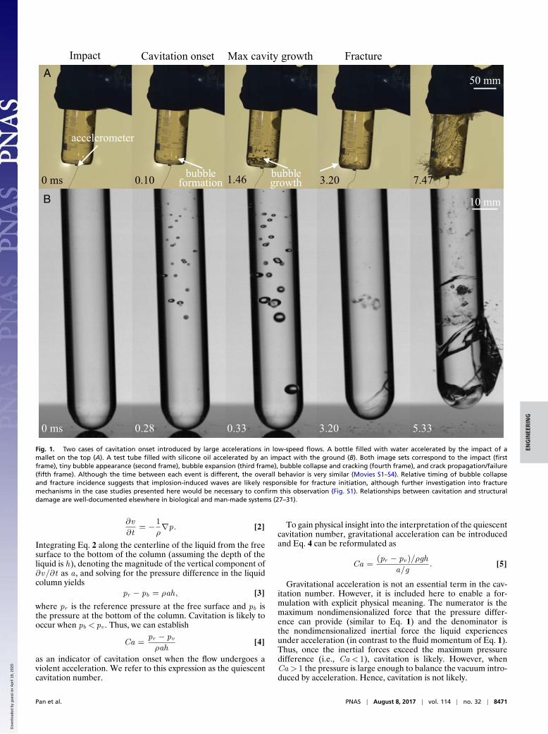
Impact Max cavity growth erutcarFtesnonoitativaC
accelerometer
bubbleformation
bubblegrowth
50 mm
10 mm
0 ms 0.28 0.33 3.20 5.33
0 ms 0.10 1.46 3.20 7.47
Fig. 1. Two cases of cavitation onset introduced by large accelerations in low-speed flows. A bottle filled with water accelerated by the impact of amallet on the top (A). A test tube filled with silicone oil accelerated by an impact with the ground (B). Both image sets correspond to the impact (firstframe), tiny bubble appearance (second frame), bubble expansion (third frame), bubble collapse and cracking (fourth frame), and crack propagation/failure(fifth frame). Although the time between each event is different, the overall behavior is very similar (Movies S1–S4). Relative timing of bubble collapseand fracture incidence suggests that implosion-induced waves are likely responsible for fracture initiation, although further investigation into fracturemechanisms in the case studies presented here would be necessary to confirm this observation (Fig. S1). Relationships between cavitation and structuraldamage are well-documented elsewhere in biological and man-made systems (27–31).
∂v
∂t= −1
ρ∇p. [2]
Integrating Eq. 2 along the centerline of the liquid from the freesurface to the bottom of the column (assuming the depth of theliquid is h), denoting the magnitude of the vertical component of∂v/∂t as a , and solving for the pressure difference in the liquidcolumn yields
pr − pb = ρah, [3]
where pr is the reference pressure at the free surface and pb isthe pressure at the bottom of the column. Cavitation is likely tooccur when pb < pv . Thus, we can establish
Ca =pr − pvρah
[4]
as an indicator of cavitation onset when the flow undergoes aviolent acceleration. We refer to this expression as the quiescentcavitation number.
To gain physical insight into the interpretation of the quiescentcavitation number, gravitational acceleration can be introducedand Eq. 4 can be reformulated as
Ca =(pr − pv )/ρgh
a/g. [5]
Gravitational acceleration is not an essential term in the cav-itation number. However, it is included here to enable a for-mulation with explicit physical meaning. The numerator is themaximum nondimensionalized force that the pressure differ-ence can provide (similar to Eq. 1) and the denominator isthe nondimensionalized inertial force the liquid experiencesunder acceleration (in contrast to the fluid momentum of Eq. 1).Thus, once the inertial forces exceed the maximum pressuredifference (i.e., Ca < 1), cavitation is likely. However, whenCa > 1 the pressure is large enough to balance the vacuum intro-duced by acceleration. Hence, cavitation is not likely.
Pan et al. PNAS | August 8, 2017 | vol. 114 | no. 32 | 8471
Dow
nloa
ded
by g
uest
on
Apr
il 18
, 202
0
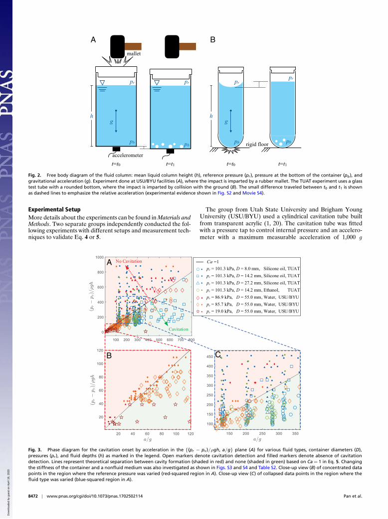
mallet
h
pr
g
accelerometer
pb
pr
pb rigid floor
pr
pb
hg
pr
pb
t=t0 t=t1 t=t0 t=t1
A B
Fig. 2. Free body diagram of the fluid column: mean liquid column height (h), reference pressure (pr ), pressure at the bottom of the container (pb), andgravitational acceleration (g). Experiment done at USU/BYU facilities (A), where the impact is imparted by a rubber mallet. The TUAT experiment uses a glasstest tube with a rounded bottom, where the impact is imparted by collision with the ground (B). The small difference traveled between t0 and t1 is shownas dashed lines to emphasize the relative acceleration (experimental evidence shown in Fig. S2 and Movie S4).
Experimental SetupMore details about the experiments can be found in Materials andMethods. Two separate groups independently conducted the fol-lowing experiments with different setups and measurement tech-niques to validate Eq. 4 or 5.
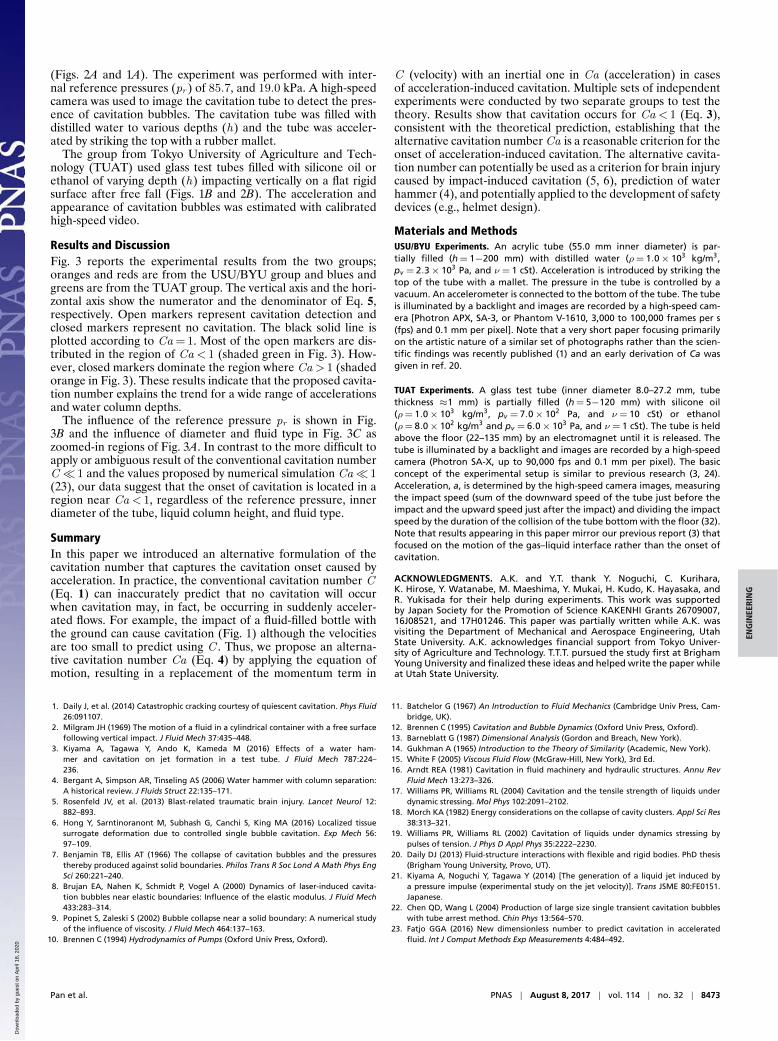
pr = 101.3 kPa, D = 8.0 mm, Silicone oil, TUATpr = 101.3 kPa, D = 14.2 mm, Silicone oil, TUATpr = 101.3 kPa, D = 27.2 mm, Silicone oil, TUAT
pr = 86.9 kPa, D = 55.0 mm, Water, USU/BYU
pr = 19.0 kPa, D = 55.0 mm, Water, USU/BYUpr = 85.7 kPa, D = 55.0 mm, Water, USU/BYU
pr = 101.3 kPa, D = 14.2 mm, Ethanol, TUAT
Ca =1No Cavitation
Cavitation
A
B C
Fig. 3. Phase diagram for the cavitation onset by acceleration in the {(pr − pv )/ρgh, a/g} plane (A) for various fluid types, container diameters (D),pressures (pr ), and fluid depths (h) as marked in the legend. Open markers denote cavitation detection and filled markers denote absence of cavitationdetection. Lines represent theoretical separation between cavity formation (shaded in red) and none (shaded in green) based on Ca = 1 in Eq. 5. Changingthe stiffness of the container and a nonfluid medium was also investigated as shown in Figs. S3 and S4 and Table S2. Close-up view (B) of concentrated datapoints in the region where the reference pressure was varied (red-squared region in A). Close-up view (C) of collapsed data points in the region where thefluid type was varied (blue-squared region in A).
The group from Utah State University and Brigham YoungUniversity (USU/BYU) used a cylindrical cavitation tube builtfrom transparent acrylic (1, 20). The cavitation tube was fittedwith a pressure tap to control internal pressure and an accelero-meter with a maximum measurable acceleration of 1,000 g
8472 | www.pnas.org/cgi/doi/10.1073/pnas.1702502114 Pan et al.
Dow
nloa
ded
by g
uest
on
Apr
il 18
, 202
0
ENG
INEE
RIN
G
(Figs. 2A and 1A). The experiment was performed with inter-nal reference pressures (pr ) of 85.7, and 19.0 kPa. A high-speedcamera was used to image the cavitation tube to detect the pres-ence of cavitation bubbles. The cavitation tube was filled withdistilled water to various depths (h) and the tube was acceler-ated by striking the top with a rubber mallet.
The group from Tokyo University of Agriculture and Tech-nology (TUAT) used glass test tubes filled with silicone oil orethanol of varying depth (h) impacting vertically on a flat rigidsurface after free fall (Figs. 1B and 2B). The acceleration andappearance of cavitation bubbles was estimated with calibratedhigh-speed video.
Results and DiscussionFig. 3 reports the experimental results from the two groups;oranges and reds are from the USU/BYU group and blues andgreens are from the TUAT group. The vertical axis and the hori-zontal axis show the numerator and the denominator of Eq. 5,respectively. Open markers represent cavitation detection andclosed markers represent no cavitation. The black solid line isplotted according to Ca =1. Most of the open markers are dis-tributed in the region of Ca < 1 (shaded green in Fig. 3). How-ever, closed markers dominate the region where Ca > 1 (shadedorange in Fig. 3). These results indicate that the proposed cavita-tion number explains the trend for a wide range of accelerationsand water column depths.
The influence of the reference pressure pr is shown in Fig.3B and the influence of diameter and fluid type in Fig. 3C aszoomed-in regions of Fig. 3A. In contrast to the more difficult toapply or ambiguous result of the conventional cavitation numberC � 1 and the values proposed by numerical simulation Ca� 1(23), our data suggest that the onset of cavitation is located in aregion near Ca < 1, regardless of the reference pressure, innerdiameter of the tube, liquid column height, and fluid type.
SummaryIn this paper we introduced an alternative formulation of thecavitation number that captures the cavitation onset caused byacceleration. In practice, the conventional cavitation number C(Eq. 1) can inaccurately predict that no cavitation will occurwhen cavitation may, in fact, be occurring in suddenly acceler-ated flows. For example, the impact of a fluid-filled bottle withthe ground can cause cavitation (Fig. 1) although the velocitiesare too small to predict using C . Thus, we propose an alterna-tive cavitation number Ca (Eq. 4) by applying the equation ofmotion, resulting in a replacement of the momentum term in
C (velocity) with an inertial one in Ca (acceleration) in casesof acceleration-induced cavitation. Multiple sets of independentexperiments were conducted by two separate groups to test thetheory. Results show that cavitation occurs for Ca < 1 (Eq. 3),consistent with the theoretical prediction, establishing that thealternative cavitation number Ca is a reasonable criterion for theonset of acceleration-induced cavitation. The alternative cavita-tion number can potentially be used as a criterion for brain injurycaused by impact-induced cavitation (5, 6), prediction of waterhammer (4), and potentially applied to the development of safetydevices (e.g., helmet design).
Materials and MethodsUSU/BYU Experiments. An acrylic tube (55.0 mm inner diameter) is par-tially filled (h = 1−200 mm) with distilled water (ρ= 1.0× 10³ kg/m3,pv = 2.3× 10³ Pa, and ν= 1 cSt). Acceleration is introduced by striking thetop of the tube with a mallet. The pressure in the tube is controlled by avacuum. An accelerometer is connected to the bottom of the tube. The tubeis illuminated by a backlight and images are recorded by a high-speed cam-era [Photron APX, SA-3, or Phantom V-1610, 3,000 to 100,000 frames per s(fps) and 0.1 mm per pixel]. Note that a very short paper focusing primarilyon the artistic nature of a similar set of photographs rather than the scien-tific findings was recently published (1) and an early derivation of Ca wasgiven in ref. 20.
TUAT Experiments. A glass test tube (inner diameter 8.0–27.2 mm, tubethickness ≈1 mm) is partially filled (h = 5−120 mm) with silicone oil(ρ= 1.0× 10³ kg/m3, pv = 7.0× 10² Pa, and ν= 10 cSt) or ethanol(ρ= 8.0× 10² kg/m3 and pv = 6.0× 10³ Pa, and ν= 1 cSt). The tube is heldabove the floor (22–135 mm) by an electromagnet until it is released. Thetube is illuminated by a backlight and images are recorded by a high-speedcamera (Photron SA-X, up to 90,000 fps and 0.1 mm per pixel). The basicconcept of the experimental setup is similar to previous research (3, 24).Acceleration, a, is determined by the high-speed camera images, measuringthe impact speed (sum of the downward speed of the tube just before theimpact and the upward speed just after the impact) and dividing the impactspeed by the duration of the collision of the tube bottom with the floor (32).Note that results appearing in this paper mirror our previous report (3) thatfocused on the motion of the gas–liquid interface rather than the onset ofcavitation.
ACKNOWLEDGMENTS. A.K. and Y.T. thank Y. Noguchi, C. Kurihara,K. Hirose, Y. Watanabe, M. Maeshima, Y. Mukai, H. Kudo, K. Hayasaka, andR. Yukisada for their help during experiments. This work was supportedby Japan Society for the Promotion of Science KAKENHI Grants 26709007,16J08521, and 17H01246. This paper was partially written while A.K. wasvisiting the Department of Mechanical and Aerospace Engineering, UtahState University. A.K. acknowledges financial support from Tokyo Univer-sity of Agriculture and Technology. T.T.T. pursued the study first at BrighamYoung University and finalized these ideas and helped write the paper whileat Utah State University.
1. Daily J, et al. (2014) Catastrophic cracking courtesy of quiescent cavitation. Phys Fluid26:091107.
2. Milgram JH (1969) The motion of a fluid in a cylindrical container with a free surfacefollowing vertical impact. J Fluid Mech 37:435–448.
3. Kiyama A, Tagawa Y, Ando K, Kameda M (2016) Effects of a water ham-mer and cavitation on jet formation in a test tube. J Fluid Mech 787:224–236.
4. Bergant A, Simpson AR, Tinseling AS (2006) Water hammer with column separation:A historical review. J Fluids Struct 22:135–171.
5. Rosenfeld JV, et al. (2013) Blast-related traumatic brain injury. Lancet Neurol 12:882–893.
6. Hong Y, Sarntinoranont M, Subhash G, Canchi S, King MA (2016) Localized tissuesurrogate deformation due to controlled single bubble cavitation. Exp Mech 56:97–109.
7. Benjamin TB, Ellis AT (1966) The collapse of cavitation bubbles and the pressuresthereby produced against solid boundaries. Philos Trans R Soc Lond A Math Phys EngSci 260:221–240.
8. Brujan EA, Nahen K, Schmidt P, Vogel A (2000) Dynamics of laser-induced cavita-tion bubbles near elastic boundaries: Influence of the elastic modulus. J Fluid Mech433:283–314.
9. Popinet S, Zaleski S (2002) Bubble collapse near a solid boundary: A numerical studyof the influence of viscosity. J Fluid Mech 464:137–163.
10. Brennen C (1994) Hydrodynamics of Pumps (Oxford Univ Press, Oxford).
11. Batchelor G (1967) An Introduction to Fluid Mechanics (Cambridge Univ Press, Cam-bridge, UK).
12. Brennen C (1995) Cavitation and Bubble Dynamics (Oxford Univ Press, Oxford).13. Barneblatt G (1987) Dimensional Analysis (Gordon and Breach, New York).14. Gukhman A (1965) Introduction to the Theory of Similarity (Academic, New York).15. White F (2005) Viscous Fluid Flow (McGraw-Hill, New York), 3rd Ed.16. Arndt REA (1981) Cavitation in fluid machinery and hydraulic structures. Annu Rev
Fluid Mech 13:273–326.17. Williams PR, Williams RL (2004) Cavitation and the tensile strength of liquids under
dynamic stressing. Mol Phys 102:2091–2102.18. Morch KA (1982) Energy considerations on the collapse of cavity clusters. Appl Sci Res
38:313–321.19. Williams PR, Williams RL (2002) Cavitation of liquids under dynamics stressing by
pulses of tension. J Phys D Appl Phys 35:2222–2230.20. Daily DJ (2013) Fluid-structure interactions with flexible and rigid bodies. PhD thesis
(Brigham Young University, Provo, UT).21. Kiyama A, Noguchi Y, Tagawa Y (2014) [The generation of a liquid jet induced by
a pressure impulse (experimental study on the jet velocity)]. Trans JSME 80:FE0151.Japanese.
22. Chen QD, Wang L (2004) Production of large size single transient cavitation bubbleswith tube arrest method. Chin Phys 13:564–570.
23. Fatjo GGA (2016) New dimensionless number to predict cavitation in acceleratedfluid. Int J Comput Methods Exp Measurements 4:484–492.
Pan et al. PNAS | August 8, 2017 | vol. 114 | no. 32 | 8473
Dow
nloa
ded
by g
uest
on
Apr
il 18
, 202
0
24. Antkowiak A, Bremond N, Dizes SL, Villermaux E (2007) Short-term dynam-ics of a density interface following an impact. J Fluid Mech 577:241–250.
25. Krechetnikov R (2014) Flow around a corner in the water impact problem. Phys Fluid26:072107.
26. Cooker MJ, Peregrine DH (1995) Pressure-impulse theory for liquid impact problems.J Fluid Mech 297:193–214.
27. Knapp RT (1955) Recent investigations of the mechanics of cavitation and cavitationdamage. Trans ASME 77:1045–1054.
28. Plesset M, Ellis A (1955) On the mechanism of cavitation damage. Trans ASME77:1055–1064.
29. Versluis M, Schmitz B, von der Heydt A, Lohse D (2000) How snapping shrimp snap:Through cavitating bubbles. Science 289:2114–2117.
30. Chen YL, Israelachvili J (1991) New mechanism of cavitation damage. Science252:1157–1160.
31. Chen YL, Kuhl T, Israelachvili J (1992) Mechanism of cavitation damage in thin liquidfilms: Collapse damage vs. inception damage. Wear 153:31–51.
32. Young FR (1989) Cavitation (McGraw-Hill, New York).
8474 | www.pnas.org/cgi/doi/10.1073/pnas.1702502114 Pan et al.
Dow
nloa
ded
by g
uest
on
Apr
il 18
, 202
0