cavity piezooptomechanics: piezoelectrically excited, optically transduced ... · 2013-01-29 ·...
TRANSCRIPT
1
Cavity piezooptomechanics: piezoelectrically excited, optically
transduced optomechanical resonators
Chi Xiong, Linran Fan, Xiankai Sun, and Hong X. Tanga)
Department of Electrical Engineering, Yale University, 15 Prospect St., New Haven, Connecticut
06511, USA
Abstract: We present a monolithic integrated aluminum nitride (AlN) optomechanical resonator
in which the mechanical motion is actuated by piezoelectric force and the displacement is
transduced by a high-Q optical cavity. The AlN optomechanical resonator is excited from a
radio-frequency electrode via a small air gap to eliminate resonator-to-electrode loss. We
observe the electrically excited mechanical motion at 47.3 MHz, 1.04 GHz, and 3.12 GHz,
corresponding to the 1st, 2
nd, and 4
th radial-contour mode of the wheel resonator respectively. An
equivalent circuit model is developed to describe the observed Fano-like resonance spectrum.
a)Electronic mail: [email protected].
2
Cavity optomechanical resonators have exhibited ultrasensitive displacement sensitivity
close to the quantum limit1 and hold promise for technological advances in metrology and
quantum information processing2. So far, optomechanical actuation has been mostly achieved via
radiation pressure effects3-6
, which are inherently weak7-9
and often give rise to deleterious
heating effects.10
Recently cavity optoelectromechanical resonators,11-13
which combine stronger
electrostatic actuation and ultrasensitive displacement readout by an optical cavity, have been
demonstrated. Electrical actuation of the optomechanical resonators could enable feedback
cooling or amplification of mechanical resonators for realizing low phase noise oscillators.
In micro- and nanoelectromechanical systems (MEMS/NEMS), piezoelectric force14, 15
can provide strong mechanical excitation besides electrostatic forces. Compared with
micromechanical resonators using electrostatic effects, piezoelectric transduction is particularly
attractive for ultrahigh-frequency applications, such as thin-film bulk acoustic resonators
(FBAR)16
and contour-mode resonators14
. In addition to piezoelectric force actuation,
conventional piezoelectric resonators usually rely on metal electrodes in contact with the device
to enable displacement readout by the piezoelectric effect, which transduces the displacement to
a sensing voltage. Compared to electrical readout, optical sensing offers superior sensitivity and
simplifies the fabrication of the device. Recently we have demonstrated an AlN cavity
optomechanical resonator in a shape reminiscent of a wheel with displacement sensitivity as high
as 6.2 × 10⁻¹⁸
m/√Hz17
. The Brownian motions of the wheel resonator were transduced optically.
In this Letter, we show that such AlN optomechanical resonators can be excited more efficiently
by piezoelectric force and we observe driven response of the mechanical resonances at 47.3
MHz, 1.04 GHz, and 3.12 GHz, corresponding to the 1st, 2
nd and 4
th radial-contour mode of the
wheel respectively. The measured mechanical Q factors are 1370, 2470, for the 47.3 MHz and
3
1.04 GHz mode in ambient air respectively. Our work points to a direction for building a class of
piezooptomechanical systems with an additional electrical degree of freedom.
The AlN wheel resonators under study are fabricated in 330-nm-thick c-axis-oriented
AlN thin films sputtered on oxidized silicon wafers. The fabrication details were described
elsewhere.18
Fig. 1(a) shows the measurement setup. Light from a tunable diode laser (TDL) is
coupled into and out of the device using a pair of grating couplers. A fiber polarization controller
(FPC) is used before the input grating coupler to select the TE-like polarization. The transmitted
light is detected by a low-noise InGaAs photoreceiver (PR). The piezoelectric transduction
usually requires the devices to be fabricated with metal electrodes in physical contact. Here in
order to avoid the optical loss induced by the metal, we separate the wheel resonator from the
electrode via a small air gap (about 50 µm), as shown in the setup diagram. The electrode is
made from a sharpened stainless steel probe with a tip diameter of about 10 µm. This contactless
design simultaneously serves to eliminate the mechanical loss from the resonator–electrode
contact while maintaining high electromechanical coupling.19
Fig. 1(b) shows the optical transmission spectrum of a typical wheel resonator which
shows a loaded optical Q factor of 125, 000. The inset shows a scanning electron micrograph of
the AlN wheel (inner radius Ri = 32.6 µm, outer radius Ro = 37.6 µm) and the zoom-in of an
optical resonance near 1544.85 nm. As shown in the schematic of Fig. 1(a), we position the
electrode in close proximity vertically above the center of the wheel, while the silicon substrate
is connected to ground. Optical transduction of the mechanical modes is performed by tuning the
input laser to the wavelength corresponding to the maximum slope of an optical resonance. We
keep the laser input power low enough so that the optomechanical back-action is negligible. The
4
transmitted light is amplified by an erbium doped optical amplifier (EDFA) and then detected by
a high-speed InGaAs photoreceiver with 4 GHz bandwidth.
The dynamic response of the AlN wheel resonator under an AC drive is characterized by
measuring S21 transmission spectrum from the network analyzer. Fig. 2 shows a wideband
spectrum of the measured magnitude and phase of S21 with zero DC bias voltage. We observe
three dominant peaks near 47.3 MHz, 1.04 GHz, and 3.12 GHz, corresponding to the 1st, 2
nd and
4th
radial-contour mode respectively. With predominant in-plane motions, these modes are
efficiently excited through the the off-diagonal component (d13) of AlN’s piezoelectric
coefficient tensor under the present electrode configuration, which provides a large out-of-plane
(Ez) field component. We do not observe the 3rd
radial-contour mode expected to be near 2.1
GHz, which can be attributed to the symmetry of the displacement profile and the vanishing
overlap integral with the vertical excitation field. We tune the DC bias voltage from 0 up to 20 V
and do not observe any change in the signal amplitude, consistent with the properties of
piezoelectric actuation. The frequencies of the respective modes agree with those obtained from
theoretical and numerical calculations.17
The mechanical resonances exhibit Fano-like asymmetric line-shape as shown in Fig. 2
(a). Generally, Fano resonance is a result of interference between a resonant process and a slowly
varying background such as nonresonant signal crosstalk. In our case, since the direct electrical
crosstalk is negligible due to the optical isolation, the electrical–optical–electrical crosstalk
originates from the Pockels eeffect17
in the AlN wheel. The cavity resonance shift (Δf) can be
written as a sum of the effects from Pockels modulation (Δfeo) and optomechanical modulation
(Δfom):
eo omf f f (1)
5
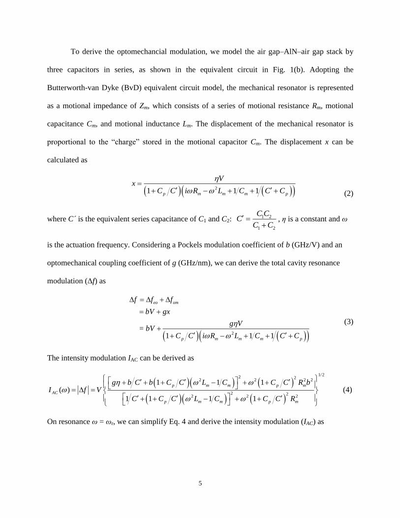
To derive the optomechancial modulation, we model the air gap–AlN–air gap stack by
three capacitors in series, as shown in the equivalent circuit in Fig. 1(b). Adopting the
Butterworth-van Dyke (BvD) equivalent circuit model, the mechanical resonator is represented
as a motional impedance of Zm, which consists of a series of motional resistance Rm, motional
capacitance Cm, and motional inductance Lm. The displacement of the mechanical resonator is
proportional to the “charge” stored in the motional capacitor Cm. The displacement x can be
calculated as
21 1 1p m m m p
Vx
C C i R L C C C
(2)
where C ́is the equivalent series capacitance of C1 and C2: 1 2
1 2
C CC
C C
, η is a constant and ω
is the actuation frequency. Considering a Pockels modulation coefficient of b (GHz/V) and an
optomechanical coupling coefficient of g (GHz/nm), we can derive the total cavity resonance
modulation (Δf) as
2
= 1 1 1
eo om
p m m m p
f f f
bV gx
g VbV
C C i R L C C C
(3)
The intensity modulation IAC can be derived as
1/22 2
2 2 2 2
2 22 2 2
1 1 1( )
1 1 1 1
p m m p m
AC
p m m p m
g b C b C C L C C C R bI f V
C C C L C C C R
(4)
On resonance ω = ωr, we can simplify Eq. 4 and derive the intensity modulation (IAC) as
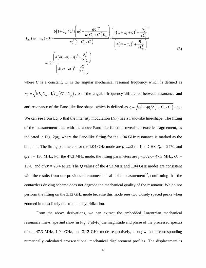
6
22 2
2
2 22
2
22
2
22
2
1 / 42
1 /4
2
42
42
mp r
rp m m
AC r
r p mr
m
mr
m
mr
m
g C Rb C C qb C C L L
I VC C R
L
Rq
LC
R
L
(5)
where C is a constant, ωr is the angular mechanical resonant frequency which is defined as
1 1r m m m pL C L C C , q is the angular frequency difference between resonance and
anti-resonance of the Fano-like line-shape, which is defined as 21 /r p rq g b C C .
We can see from Eq. 5 that the intensity modulation (IAC) has a Fano-like line-shape. The fitting
of the measurement data with the above Fano-like function reveals an excellent agreement, as
indicated in Fig. 2(a), where the Fano-like fitting for the 1.04 GHz resonance is marked as the
blue line. The fitting parameters for the 1.04 GHz mode are fr=ωr/2 = 1.04 GHz, Qm = 2470, and
q/2 = 130 MHz. For the 47.3 MHz mode, the fitting parameters are fr=ωr/2 = 47.3 MHz, Qm =
1370, and q/2 = 25.4 MHz. The Q values of the 47.3 MHz and 1.04 GHz modes are consistent
with the results from our previous thermomechanical noise measurement17
, confirming that the
contactless driving scheme does not degrade the mechanical quality of the resonator. We do not
perform the fitting on the 3.12 GHz mode because this mode sees two closely spaced peaks when
zoomed in most likely due to mode hybridization.
From the above derivations, we can extract the embedded Lorentzian mechanical
resonance line-shape and show in Fig. 3(a)–(c) the magnitude and phase of the processed spectra
of the 47.3 MHz, 1.04 GHz, and 3.12 GHz mode respectively, along with the corresponding
numerically calculated cross-sectional mechanical displacement profiles. The displacement is
7
calculated by comparing the measured voltage noise spectral density and the displacement noise
spectral density and then deducing the transduction gain (V/m) of the device. A large
enhancement of the mechanical displacement is observed as the RF drive signal approaches the
mechanical resonant frequency. For the 2nd
radial-contour mode at 1.04 GHz, we also measure
the spectra under different driving power from −30 dBm to 0 dBm. The on-resonance
displacement as a function of the rms voltage applied on the electrode is plotted in Fig. 3(b)
inset, showing a linear relationship which indicates that the resonator still operates in the linear
regime. For the 47.3 MHz and 3.12 GHz modes, the excitation power is fixed at 0 dBm.
The magnitude of the piezoelectric driving force (Fpz) can be calculated by Fpz =
k·x(ωr)/Qm = ω2meff∙x(ωr)/Qm, where k is the spring constant of a mechanical mode, x(ωr) is the
mechanical displacement on resonance and Qm is the mechanical quality factor. For the 1.04
GHz mode, the effective mass is 0.42 ng, the on-resonance displacement is 3 × 10⁻¹¹
m for RF
power of 0 dBm (1 mW), the piezoelectric force at this RF power can then be calculated as 0.22
µN. We can further compare the magnitude of the piezoelectric force to that of the optical force
and the electrostatic force in our system. The optical force can be calculated as Fo=|a|2gom/ω,
where ω is the optical cavity frequency (2 ×194 THz), gom is the optomechanical coupling
coefficient (gom~ω/R=2 ×6.0 GHz/nm). The intra-cavity field intensity |a|2 can be calculated as
2
2 2
2 cPa
, where κc is the cavity dissipation rate (2 ×0.5 GHz), κ is the cavity coupling rate
(2 ×1 GHz), Δ is the cavity detuning (2 ×1 GHz), P is the input optical power (1 mW). After
plugging the values of each of the quantities, we obtain the optical force as Fo=2.5 nN. The
electrostatic dipole force in our system can be estimated by 21
2el DC
dCF V
dg when applying a DC
voltage VDC over a capacitor C and a gap of g. For an electrode to device gap of 50 µm we
8
estimate C~0.2 fF and Fel~1.9 pN/VDC2. It is evident that the piezoelectric force is the dominant
force in our system.
In conclusion, we have demonstrated a monolithic piezoelectrically actuated aluminum
nitride optomechanical resonator operating at frequencies up to 3.12 GHz. By taking advantage
of the piezoelectric driving force as large as 0.22 µN and high displacement sensitivity offered
by a high-Q optical cavity, the radial-contour modes of the wheel resonators are efficiently
excited and optically read out. Using on-chip electrodes in future experiments could further
enhance the excitation efficiency and provide access to study the nonlinear dynamics of
optomechanical resonator under strong piezoelectric drive. These AlN piezoelectric
optomechanical resonators can be employed to build low-switching-voltage optical modulators11
and low-phase-noise opto-acoustic oscillators.20
Our piezo-opto-mechanical system can also find
applications for optomechanical cooling and amplification by using electrical feedback.
9
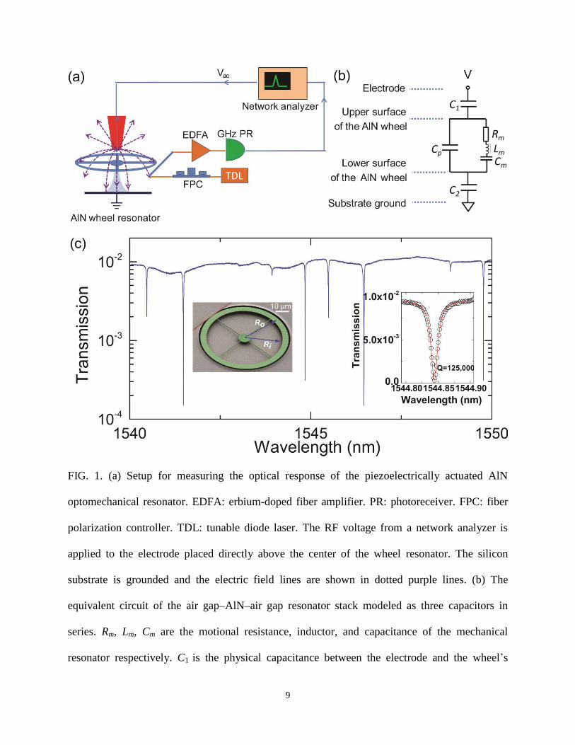
FIG. 1. (a) Setup for measuring the optical response of the piezoelectrically actuated AlN
optomechanical resonator. EDFA: erbium-doped fiber amplifier. PR: photoreceiver. FPC: fiber
polarization controller. TDL: tunable diode laser. The RF voltage from a network analyzer is
applied to the electrode placed directly above the center of the wheel resonator. The silicon
substrate is grounded and the electric field lines are shown in dotted purple lines. (b) The
equivalent circuit of the air gap–AlN–air gap resonator stack modeled as three capacitors in
series. Rm, Lm, Cm are the motional resistance, inductor, and capacitance of the mechanical
resonator respectively. C1 is the physical capacitance between the electrode and the wheel’s
10
upper surface, C2 is the physical capacitance between the wheel’s lower surface and the ground
and Cp is the dielectric capacitance of the AlN device layer. (c) Typical optical transmission of an
AlN wheel optomechanical resonator with the inner radius Ri = 32.6 µm and outer radius Ro =
37.6 µm. The left inset is a scanning electron micrograph of the AlN wheel resonator and the
right inset is the zoom-in of a resonance near 1544.85 nm with a loaded optical Q factor of
125,000.
11
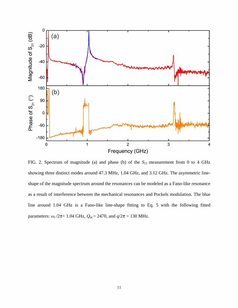
FIG. 2. Spectrum of magnitude (a) and phase (b) of the S21 measurement from 0 to 4 GHz
showing three distinct modes around 47.3 MHz, 1.04 GHz, and 3.12 GHz. The asymmetric line-
shape of the magnitude spectrum around the resonances can be modeled as a Fano-like resonance
as a result of interference between the mechanical resonances and Pockels modulation. The blue
line around 1.04 GHz is a Fano-like line-shape fitting to Eq. 5 with the following fitted
parameters: ωr /2 = 1.04 GHz, Qm = 2470, and q/2 = 130 MHz.
12
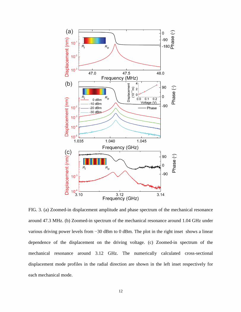
FIG. 3. (a) Zoomed-in displacement amplitude and phase spectrum of the mechanical resonance
around 47.3 MHz. (b) Zoomed-in spectrum of the mechanical resonance around 1.04 GHz under
various driving power levels from −30 dBm to 0 dBm. The plot in the right inset shows a linear
dependence of the displacement on the driving voltage. (c) Zoomed-in spectrum of the
mechanical resonance around 3.12 GHz. The numerically calculated cross-sectional
displacement mode profiles in the radial direction are shown in the left inset respectively for
each mechanical mode.
13
References:
1 J. Chan, T. P. M. Alegre, A. H. Safavi-Naeini, J. T. Hill, A. Krause, S. Groblacher, M.
Aspelmeyer, and O. Painter, Nature 478, 89 (2011). 2
S. Mancini, D. Vitali, and P. Tombesi, Phys Rev Lett 90, 137901 (2003). 3
T. J. Kippenberg and K. J. Vahala, Opt Express 15, 17172 (2007). 4
M. Eichenfield, J. Chan, R. M. Camacho, K. J. Vahala, and O. Painter, Nature 462, 78 (2009). 5
M. Li, W. H. P. Pernice, C. Xiong, T. Baehr-Jones, M. Hochberg, and H. X. Tang, Nature 456,
480 (2008). 6
X. K. Sun, K. Y. Fong, C. Xiong, W. H. P. Pernice, and H. X. Tang, Opt Express 19, 22316
(2011). 7
M. A. Taylor, A. Szorkovszky, J. Knittel, K. H. Lee, T. G. McRae, and W. P. Bowen, Opt
Express 20, 12742 (2012). 8
T. G. McRae, K. H. Lee, G. I. Harris, J. Knittel, and W. P. Bowen, Phys Rev A 82, 023825
(2010). 9
M. Winger, T. D. Blasius, T. P. M. Alegre, A. H. Safavi-Naeini, S. Meenehan, J. Cohen, S.
Stobbe, and O. Painter, Opt Express 19, 24905 (2011). 10
A. Schliesser, O. Arcizet, R. Riviere, G. Anetsberger, and T. J. Kippenberg, Nat Phys 5, 509
(2009). 11
S. Sridaran and S. A. Bhave, Opt Express 19, 9020 (2011). 12
K. H. Lee, T. G. McRae, G. I. Harris, J. Knittel, and W. P. Bowen, Phys Rev Lett 104, 123604
(2010). 13
X. Sun, X. Zhang, M. Poot, C. Xiong, and H. X. Tang, Appl Phys Lett 101, 221116 (2012). 14
G. Piazza, P. J. Stephanou, and A. P. Pisano, J Microelectromech S 15, 1406 (2006). 15
R. B. Karabalin, M. H. Matheny, X. L. Feng, E. Defay, G. Le Rhun, C. Marcoux, S. Hentz, P.
Andreucci, and M. L. Roukes, Appl Phys Lett 95, 103111 (2009). 16
R. C. Ruby, P. Bradley, Y. Oshmyansky, A. Chien, and J. D. Larson, III, in Ultrasonics
Symposium, 2001 IEEE, 2001), p. 813. 17
C. Xiong, X. K. Sun, K. Y. Fong, and H. X. Tang, Appl Phys Lett 100, 171111 (2012). 18
W. H. P. Pernice, C. Xiong, C. Schuck, and H. X. Tang, Appl Phys Lett 100, 091105 (2012). 19
H. Li-Wen and C. T. C. Nguyen, in Micro Electro Mechanical Systems (MEMS), 2011 IEEE 24th
International Conference on, 2011), p. 173. 20
S. Sridaran and S. A. Bhave, in Micro Electro Mechanical Systems (MEMS), 2012 IEEE 25th
International Conference on, 2012), p. 664.