cbe cleanroom management & qualification day3 - dcvmn · iso-14644-4 cleanrooms and associated...
TRANSCRIPT
11/11/15
1
© CBE – 023 V2
Cleanroom Management and Qualification
© CBE Pty Ltd
This training program is copyright to CBE Pty Ltd and may not be modified, reproduced, sold, loaned, hired or traded in any form without its the
express written permission.
1
© CBE – 023 V2
Module Topics
Specifica(ons and the V Model
Qualifica(on of HVAC Systems
Qualifica(on of Sterile Cleanrooms
Cleanrooms and GMPs
Introduc(on

11/11/15
2
© CBE – 023 V2
Some Important Reg. References EU/PICs/TGA cGMP Annex 1 – Sterile Products
PDA Technical Report #13 Fundamentals of an Environmental Monitoring Program
USP <1116> Microbiological Evaluation of Cleanrooms
FDA Guidance – Aseptic Processing
ISO 14644 Series - Cleanrooms and associated controlled environments
WHO guidelines on good manufacturing practices for heating, ventilation and air-conditioning systems for non-sterile pharmaceutical dosage forms (Annex 5) – mainly for OSD Forms
WHO good practices for pharmaceutical microbiology laboratories (Annex 2) PIC/S PI 009-1 Inspection of Utilities – Aide Memoire
3
© CBE – 023 V2
Who Writes the Cleanroom Standards?
ISO TC / 209 – Experts by country, formed into Working Groups
ISO 14644 – Cleanrooms and associated controlled environments
ISO 14698 – Biocontamination control
Australian Standards ME – 060 Controlled Atmospheres – Representatives of
Australian and New Zealand Organisations AS 1807 Suite of standards – Cleanroom Testing
AS 2252 Suite of standards – Cleanroom Devices
AS/NZS ISO 14644 Suite of standards
AS4273 – Pharmaceutical isolators

11/11/15
3
© CBE – 023 V2
TC / 209 - Standards
ISO 14644 – Cleanrooms and associated clean environments
Part 1: Classification of air cleanliness
Part 2: Specifications for testing and monitoring to prove continued compliance with ISO 14644-1
Part 3: Test methods
Part 4: Design, construction and start-up
Part 5: Operations
Part 7: Separative devices (clean air hoods, gloveboxes, isolators, and mini-environments)
© CBE – 023 V2
TC / 209 - Standards cont. ISO 14644 – Cleanrooms and associated clean environments cont.
Part 8: Classification of air cleanliness by chemical concentration (ACC)
Part 9: Classification of surface cleanliness by particle concentration
Part 10: Classification of surface cleanliness by chemical concentration
Part 12: Classification of air cleanliness by nanoscale particle concentration
ISO 14698 – Cleanrooms and associated controlled environments — Biocontamination control:
Part 1: General principles and methods
Part 2: Evaluation and interpretation of biocontamination data
11/11/15
4
© CBE – 023 V2
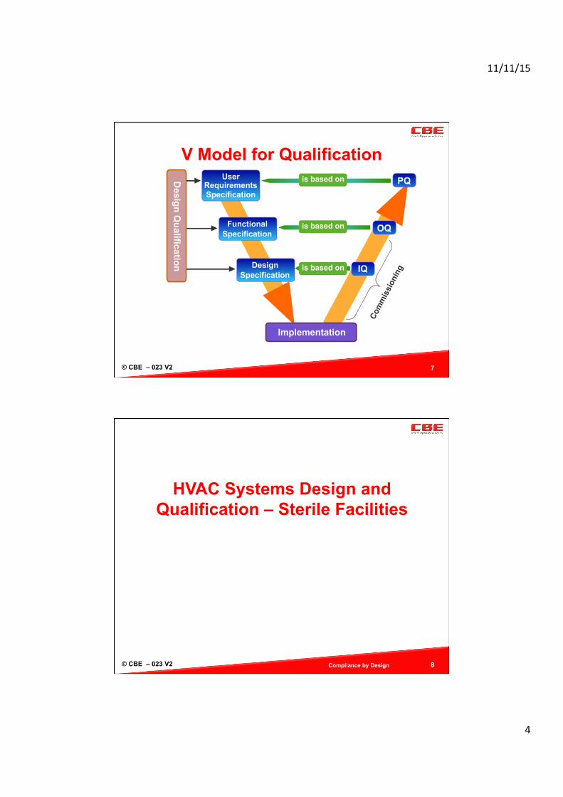
V Model for Qualification
7
© CBE – 023 V2
HVAC Systems Design and
Qualification – Sterile Facilities
Compliance by Design 8

11/11/15
5
© CBE – 023 V2 Compliance by Design 9
GMP Manufacturing Environment
PRODUCT PROTECTION
Contamination Control (product and staff)
Protect from Product Cross Contamination
Correct Temp. RH%
PERSONNEL PROTECTION
Prevent Contact with Dust
Prevent Contact with Fumes
Operator Comfort Conditions
ENVIRONMENTAL PROTECTION
Avoid Dust Discharge
Avoid Fume Discharge
Avoid Effluent Discharge
© CBE – 023 V2 10
HVAC Standards ISO 14644 - Cleanrooms and Associated Controlled Environments
ISO Document Title ISO-14644-1 Classification of Air Cleanliness ISO-14644-2 Cleanrooms and associated controlled environments. Specifications for
testing and monitoring to prove continued compliance with ISO 14644-1 ISO-14644-3 Cleanrooms and associated controlled environments. Test methods ISO-14644-4 Cleanrooms and associated controlled environments Design, Construction
and Startup ISO-14644-5 Cleanrooms and associated controlled environments. Operations ISO-14644-6 Terms, Definitions & Units ISO-14644-7 Cleanrooms and associated controlled environments. Separative devices
(clean air hoods, gloveboxes, isolators and mini-environments) ISO-14644-8 Cleanrooms and associated controlled environments. Classification of
airborne molecular contamination ISO-14698-1 Biocontamination: Control General Principles ISO-14698-2 Biocontamination: Evaluation & Interpretation of Data ISO-14698-3 Methodology for Measuring Efficiency of Cleaning Inert Surfaces
11/11/15
6
© CBE – 023 V2
HVAC – what should we consider?
Should provide a suitable environment for the product and the process staff in terms of temperature, humidity, and air cleanliness.
Cleanliness means suitable control over particulates, product residues, external contaminants and microbes.
Removal of airborne contamination by directing it to collection points and return air systems,
Should be easily (continuously) monitored and maintained at suitable intervals,
Suitable locations for filters on both supply and return (where needed)
A HEPA filter provides 99.997% efficiency at 0.3µm, where a typical pharmaceutical particulate is much larger.
Compliance by Design 11
© CBE – 023 V2
HVAC – it’s importance
Supply clean “Pure” air (a known standard) to the production environment via terminal HEPA filters
Regulates the Room Temperature and Relative Humidity
Cleanroom airflows should capture airborne particles and direct them away from product and the filling zone
Exclude microbes and particles from the environment Create pressure differentials between different work
zones and levels of cleanliness – exclusion and containment options.
12
11/11/15
7
© CBE – 023 V2
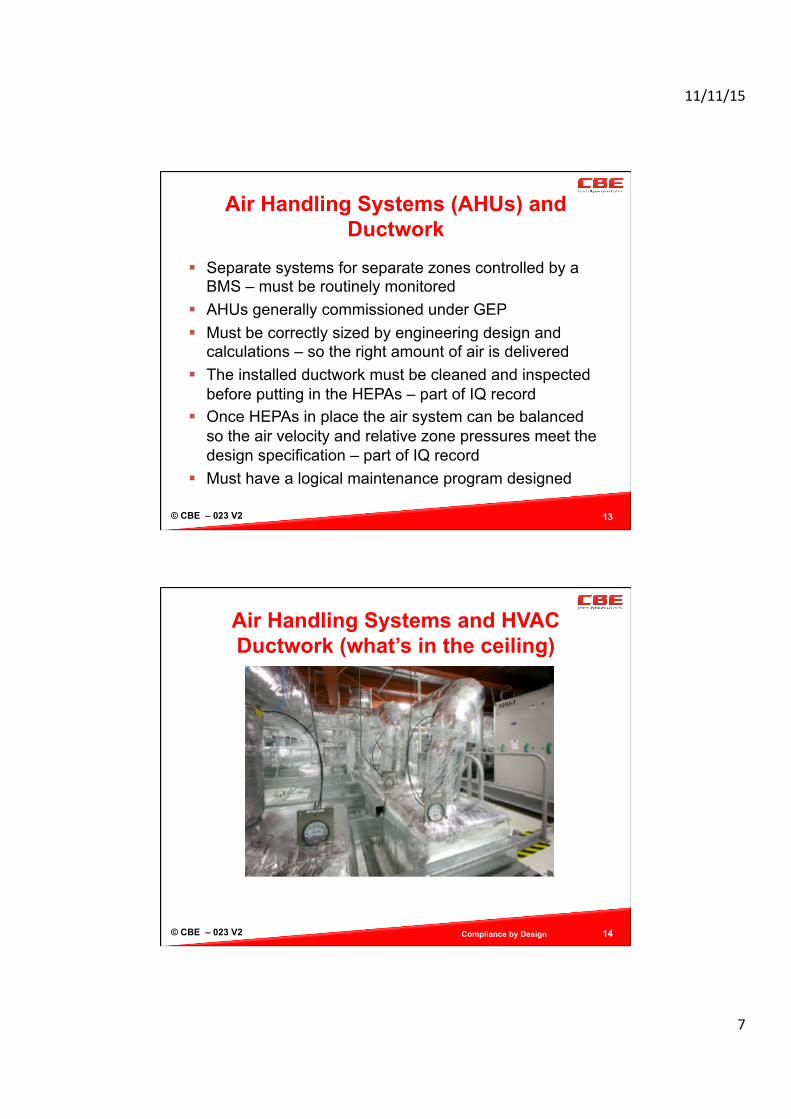
Air Handling Systems (AHUs) and Ductwork
Separate systems for separate zones controlled by a BMS – must be routinely monitored
AHUs generally commissioned under GEP Must be correctly sized by engineering design and
calculations – so the right amount of air is delivered The installed ductwork must be cleaned and inspected
before putting in the HEPAs – part of IQ record Once HEPAs in place the air system can be balanced
so the air velocity and relative zone pressures meet the design specification – part of IQ record
Must have a logical maintenance program designed
13
© CBE – 023 V2
Air Handling Systems and HVAC Ductwork (what’s in the ceiling)
Compliance by Design 14
11/11/15
8
© CBE – 023 V2 15
Room Air filters
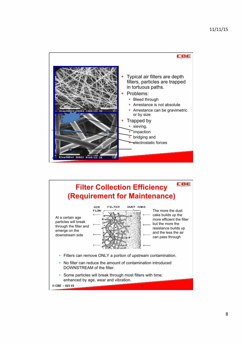
Typical air filters are depth filters, particles are trapped in tortuous paths.
Problems: Bleed through Arrestance is not absolute Arrestance can be gravimetric
or by size Trapped by
sieving, impaction bridging and electrostatic forces
Module SP6436- 3 Ver 1.0
© CBE – 023 V2 16
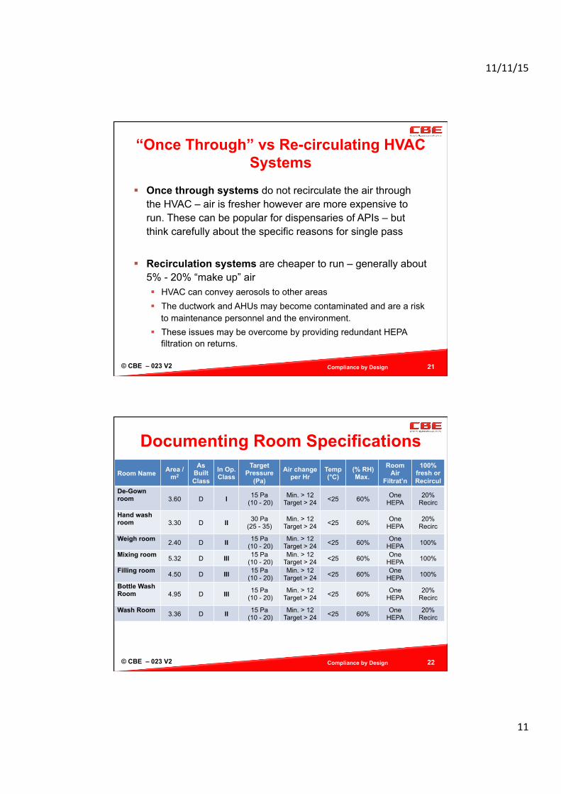
The more the dust cake builds up the more efficient the filter but the more the resistance builds up and the less the air can pass through
At a certain age particles will break through the filter and emerge on the downstream side
Filter Collection Efficiency (Requirement for Maintenance)
• Filters can remove ONLY a portion of upstream contamination.
• No filter can reduce the amount of contamination introduced DOWNSTREAM of the filter.
• Some particles will break through most filters with time; enhanced by age, wear and vibration.

11/11/15
9
© CBE – 023 V2
High Efficiency Particulate Air
17
• Generally Terminally located
• For containment purposes can have HEPA on Returns
• Over time the pressure across the filter increases
• Use of Pre-filters extend the life of HEPA filters
• Must be tested for leakage / integrity on install and periodically
• Should consider a replacement plan
© CBE – 023 V2
Leak Testing of HEPAs - Aerosols
ISO 14644-3: Cleanrooms and associated controlled environments; Test methods. Suitable aerosols include:
Poly-alpha-olefin (PAO) Dioctylphthalate (DOP) – being phased out due ot safety
concerns Particles are specific sizes to provide an even challenge to the
filter Must know the incoming challenge to ensure the test is suitable
- Particles will lodge on upstream filter Scan downstream with calibrated particle counter Must make sure particles don’t promote microbial growth
18

11/11/15
10
© CBE – 023 V2
Manufacturing Cleanrooms Design Considerations – Product Protection
hazardous nature of the Materials being processed process being carried out (open or closed system) product containment or environment exclusion needed material and personnel flow into & within the room gowning procedures equipment movement between zones occupancy – how many staff will normally work here? cleaning standard operating procedures (SOPs).
Compliance by Design 19
© CBE – 023 V2
Manufacturing Rooms Key Design Considerations - Facility
100% fresh outside air or % re-circulation air filtration systems (HEPA or not) material and personnel airlocks (MALs and PALs) relative room pressures (cascades) & air change/
flushing rate location of air inlet and exit points and directional airflow outside air design conditions (temp. and RH%) temperature and relative humidity controls needed for
products Room & equipment surface finishes and cleanability
Compliance by Design 20
11/11/15
11
© CBE – 023 V2
“Once Through” vs Re-circulating HVAC Systems
Once through systems do not recirculate the air through the HVAC – air is fresher however are more expensive to run. These can be popular for dispensaries of APIs – but think carefully about the specific reasons for single pass
Recirculation systems are cheaper to run – generally about 5% - 20% “make up” air HVAC can convey aerosols to other areas The ductwork and AHUs may become contaminated and are a risk
to maintenance personnel and the environment. These issues may be overcome by providing redundant HEPA
filtration on returns.
Compliance by Design 21
© CBE – 023 V2
Documenting Room Specifications
Compliance by Design 22
Room Name Area / m2
As Built Class
In Op. Class
Target Pressure
(Pa)
Air change per Hr
Temp (°C)
(% RH) Max.
Room Air
Filtrat’n
100% fresh or Recircul
De-Gown room
3.60 D I 15 Pa (10 - 20)
Min. > 12 Target > 24 <25 60% One
HEPA 20%
Recirc
Hand wash room
3.30 D II 30 Pa (25 - 35)
Min. > 12 Target > 24 <25 60% One
HEPA 20%
Recirc
Weigh room 2.40 D II 15 Pa
(10 - 20) Min. > 12
Target > 24 <25 60% One HEPA 100%
Mixing room 5.32 D III 15 Pa
(10 - 20) Min. > 12
Target > 24 <25 60% One HEPA 100%
Filling room 4.50 D III 15 Pa
(10 - 20) Min. > 12
Target > 24 <25 60% One HEPA 100%
Bottle Wash Room
4.95 D III 15 Pa (10 - 20)
Min. > 12 Target > 24 <25 60% One
HEPA 20%
Recirc
Wash Room 3.36 D II 15 Pa
(10 - 20) Min. > 12
Target > 24 <25 60% One HEPA
20% Recirc
11/11/15
12
© CBE – 023 V2 23
air
as built
air air
at rest in opera(on
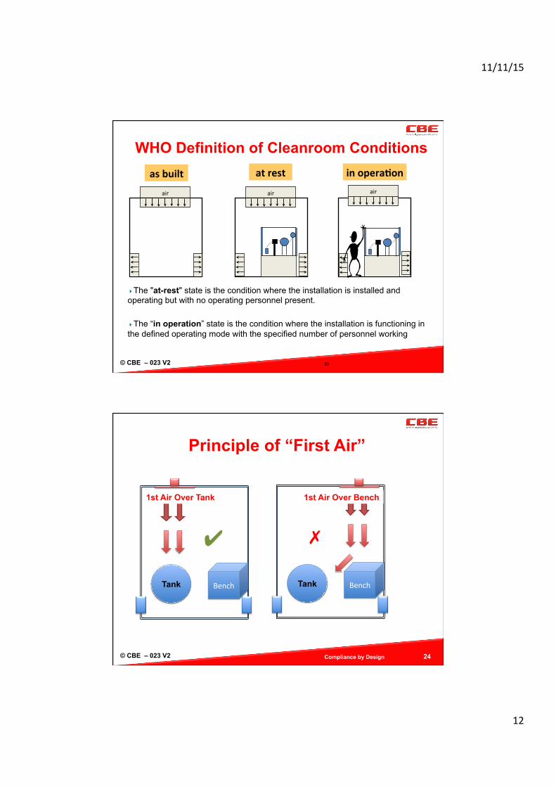
WHO Definition of Cleanroom Conditions
The "at-rest" state is the condition where the installation is installed and operating but with no operating personnel present.
The “in operation” state is the condition where the installation is functioning in the defined operating mode with the specified number of personnel working
© CBE – 023 V2
Principle of “First Air”
Compliance by Design 24
1st Air Over Tank
Tank Bench
✔
1st Air Over Bench
Tank Bench
✗
11/11/15
13
© CBE – 023 V2
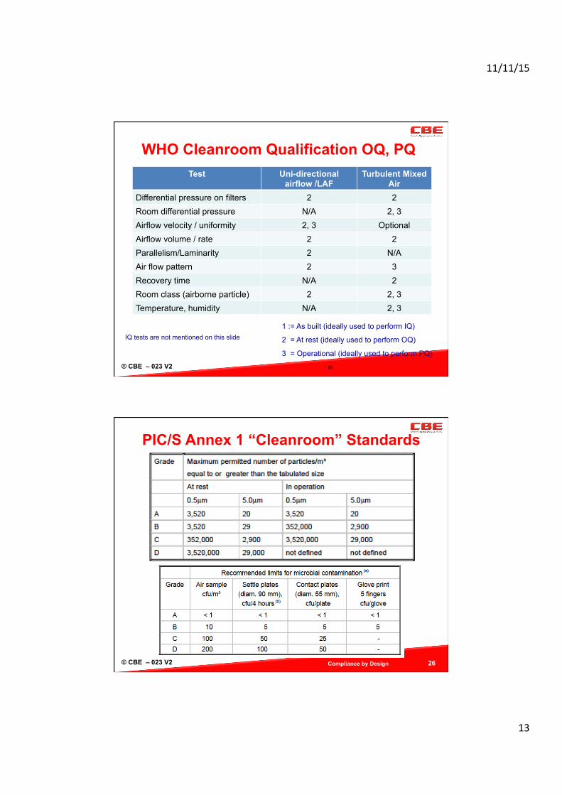
WHO Cleanroom Qualification OQ, PQ
25
1 := As built (ideally used to perform IQ)
2 = At rest (ideally used to perform OQ)
3 = Operational (ideally used to perform PQ)
IQ tests are not mentioned on this slide
Test Uni-directional airflow /LAF
Turbulent Mixed Air
Differential pressure on filters 2 2 Room differential pressure N/A 2, 3 Airflow velocity / uniformity 2, 3 Optional Airflow volume / rate 2 2 Parallelism/Laminarity 2 N/A Air flow pattern 2 3 Recovery time N/A 2 Room class (airborne particle) 2 2, 3 Temperature, humidity N/A 2, 3
© CBE – 023 V2
PIC/S Annex 1 “Cleanroom” Standards
Compliance by Design 26
11/11/15
14
© CBE – 023 V2
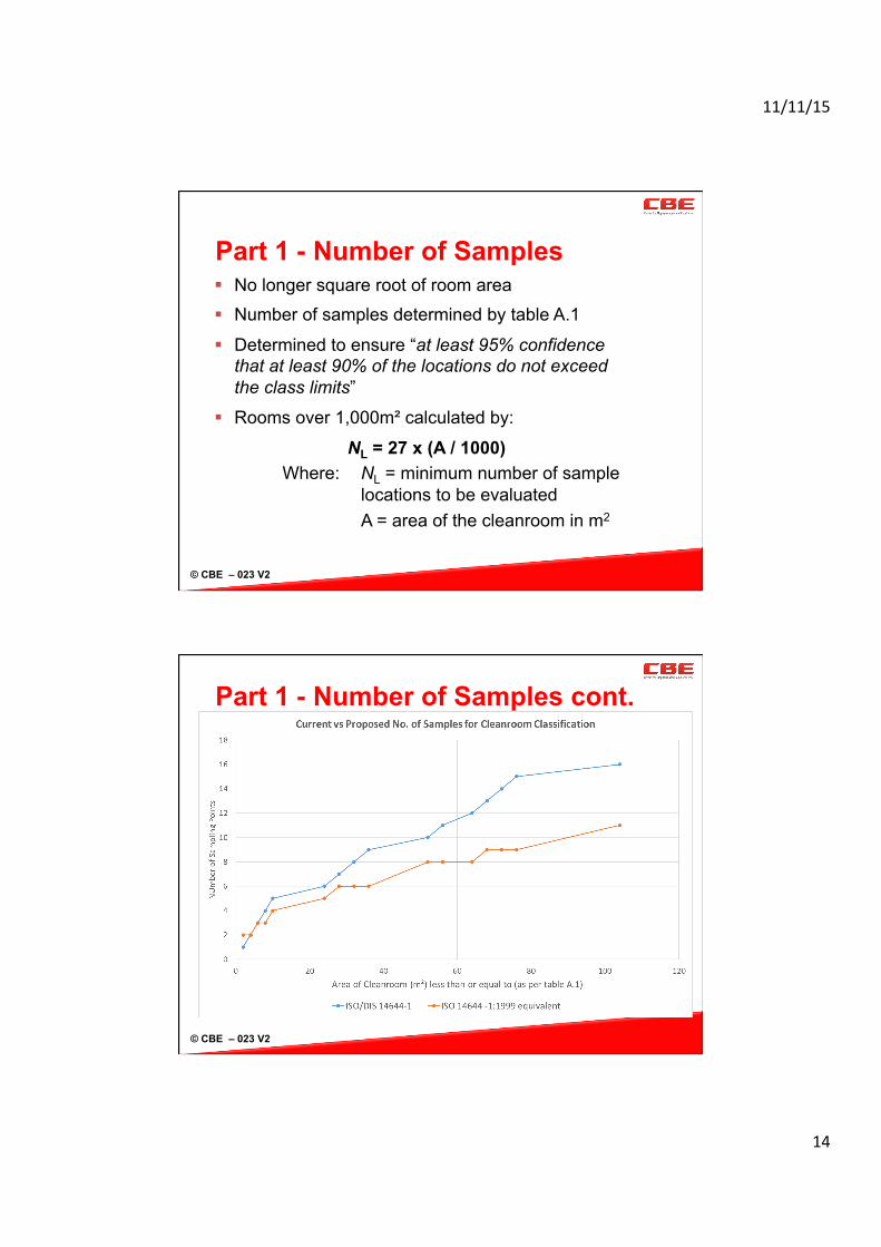
Part 1 - Number of Samples No longer square root of room area Number of samples determined by table A.1
Determined to ensure “at least 95% confidence that at least 90% of the locations do not exceed the class limits”
Rooms over 1,000m² calculated by:
NL = 27 x (A / 1000) Where: NL = minimum number of sample
locations to be evaluated A = area of the cleanroom in m2
© CBE – 023 V2
Part 1 - Number of Samples cont.
11/11/15
15
© CBE – 023 V2
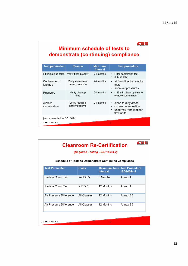
Minimum schedule of tests to demonstrate (continuing) compliance
Test parameter Reason Max. time interval
Test procedure
Filter leakage tests Verify filter integrity
24 months • Filter penetration test • (HEPA only)
Containment leakage
Verify absence of cross contam’n
24 months
• airflow direction smoke tests
• room air pressures. Recovery Verify cleanup
time
24 months
• < 15 min clean up time to remove contaminant
Airflow visualization
Verify required airflow patterns
24 months
• clean to dirty areas • cross-contamination • uniformly from laminar
flow units.
29
(recommended in ISO14644)
© CBE – 023 V2 30
Cleanroom Re-Certification (Required Testing - ISO 14644-2)
Test Parameter Class Maximum Time Interval
Test Procedure ISO14644-2
Particle Count Test <= ISO 5 6 Months Annex A
Particle Count Test > ISO 5 12 Months Annex A
Air Pressure Difference All Classes 12 Months Annex B5
Air Pressure Difference All Classes 12 Months Annex B5
Schedule of Tests to Demonstrate Continuing Compliance
11/11/15
16
© CBE – 023 V2 31
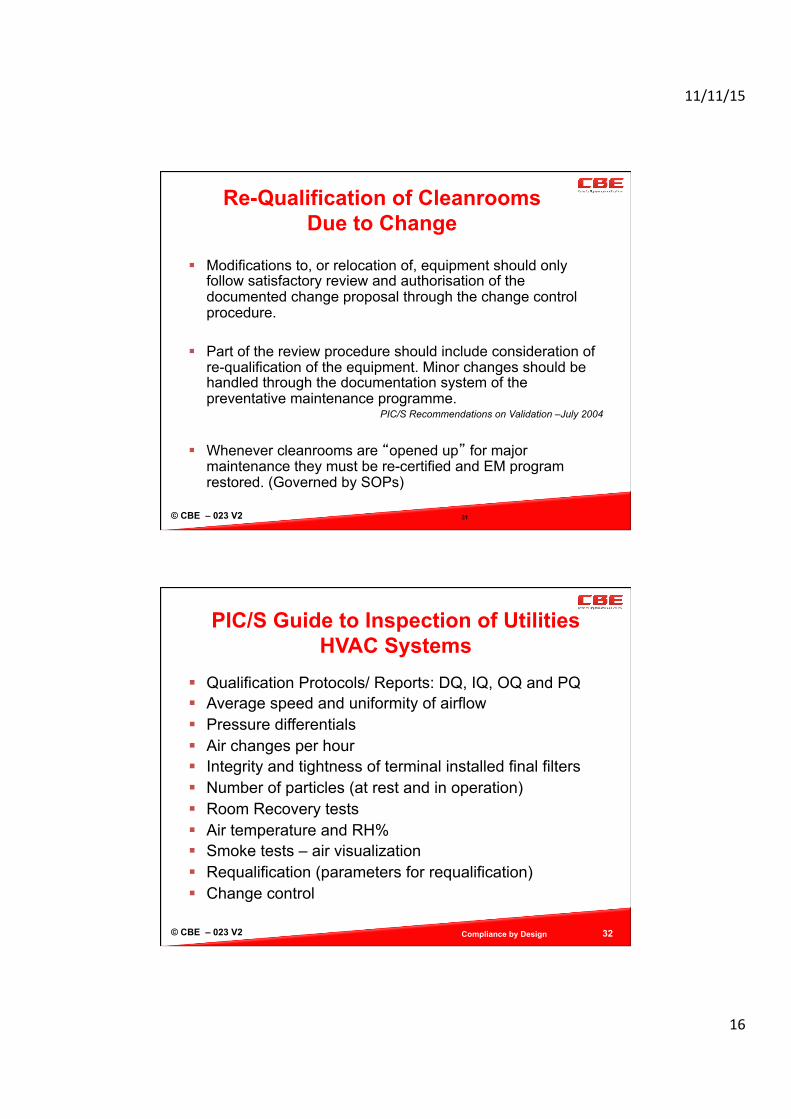
Re-Qualification of Cleanrooms Due to Change
Modifications to, or relocation of, equipment should only follow satisfactory review and authorisation of the documented change proposal through the change control procedure.
Part of the review procedure should include consideration of re-qualification of the equipment. Minor changes should be handled through the documentation system of the preventative maintenance programme.
PIC/S Recommendations on Validation –July 2004
Whenever cleanrooms are “opened up” for major maintenance they must be re-certified and EM program restored. (Governed by SOPs)
© CBE – 023 V2
PIC/S Guide to Inspection of Utilities HVAC Systems
Qualification Protocols/ Reports: DQ, IQ, OQ and PQ Average speed and uniformity of airflow Pressure differentials Air changes per hour Integrity and tightness of terminal installed final filters Number of particles (at rest and in operation) Room Recovery tests Air temperature and RH% Smoke tests – air visualization Requalification (parameters for requalification) Change control
Compliance by Design 32
11/11/15
17
© CBE – 023 V2
PIC/S Guide to Inspection of Utilities (Critical Questions from Inspectors)
Review of HVAC system drawings Is the BMS qualified ? How have you implemented recommendations and correct
deviations mentioned in qualification reports? Who is responsible for evaluating if requalification is
necessary? What are the requirements for regular requalification? Show me your deviations and change control reports for
HVAC? How do you challenge your alarm systems? Place and procedure for sampling? Where and how do you weigh and refill starting materials?
Compliance by Design 33
© CBE – 023 V2 34
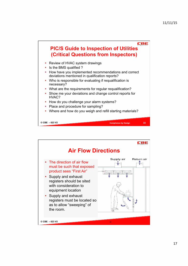
Air Flow Directions
The direction of air flow must be such that exposed product sees “First Air”
Supply and exhaust registers should be sited with consideration to equipment location
Supply and exhaust registers must be located so as to allow “sweeping” of the room.
11/11/15
18
© CBE – 023 V2
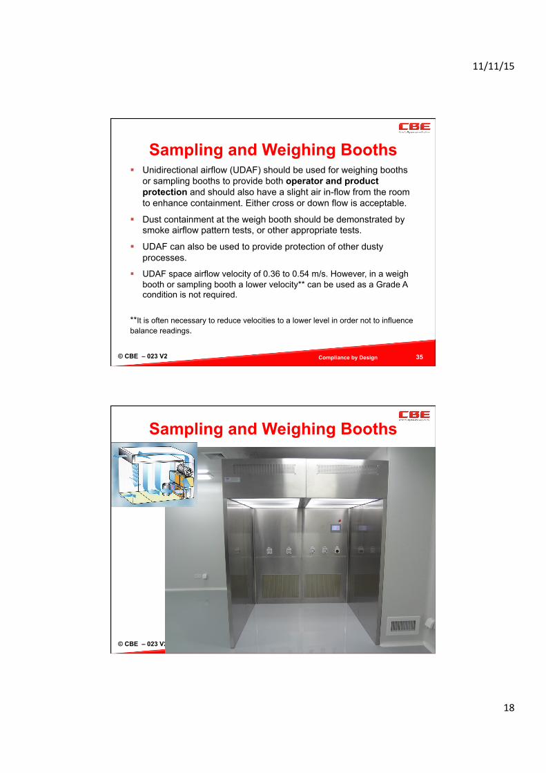
Sampling and Weighing Booths Unidirectional airflow (UDAF) should be used for weighing booths
or sampling booths to provide both operator and product protection and should also have a slight air in-flow from the room to enhance containment. Either cross or down flow is acceptable.
Dust containment at the weigh booth should be demonstrated by smoke airflow pattern tests, or other appropriate tests.
UDAF can also be used to provide protection of other dusty processes.
UDAF space airflow velocity of 0.36 to 0.54 m/s. However, in a weigh booth or sampling booth a lower velocity** can be used as a Grade A condition is not required.
**It is often necessary to reduce velocities to a lower level in order not to influence balance readings.
Compliance by Design 35
© CBE – 023 V2
Sampling and Weighing Booths
Compliance by Design 36

11/11/15
19
© CBE – 023 V2
Material and Personnel Airlocks
Compliance by Design 37
are NOT GMP storage areas to prevent mechanical transfer of
product from the processing room to the GMP corridor
to separate gowning standards between rooms
to provide a means to maintain pressure cascades
to prevent contamination of the facility and product by external contaminants
Exclusion MAL Design and Opera(on
Outer – Lower Grade
Inner – Higher Grade
HEPA In
Air Return
Clean Side
Dirty Side Transit Space
© CBE – 023 V2
Alternative MAL/PAL Designs
Compliance by Design 38
Containment MAL One Way Flow
30Pa Corridor
22.5 Pa MAL
15Pa Process Room
Containment with MAL Overpressure
15Pa Corridor
30 Pa “Bubble” MAL
15Pa Process Room
Containment with MAL as Sink
20Pa+ Outer
20Pa+ Process Room
HEPA
5 Pa “Sink” MAL

11/11/15
20
© CBE – 023 V2
Particulate Generation and Removal Grade B Rooms
Compliance by Design 39
Low Velocity Air 0.3 m/s
Low Returns
“Uni DirecOonal” Air Flow
High Velocity Air
Low or High Returns
Non Uni DirecOonal Air Flow
“Dead Space”
© CBE – 023 V2
Calculating Actual Air Change Rates
Must know: Volume of the room in
cubic metres Surface area of the
inlet HEPA in sq metres Velocity of filtered inlet
air through the HEPA B, C & D rooms usually
require 20 changes per hour
Compliance by Design 40
Example Volume room = 60 cubic
metres (4 x 5 x 3) HEPA area = 2.0 sq. metres Air Inlet Velocity = 0.3m/sec. Calculation: Inlet volume / hour = 1080 x 2.0 = 2160 cubic metres / hour Air Change Rate = 2160 / 60 = 36 changes per hour
11/11/15
21
© CBE – 023 V2
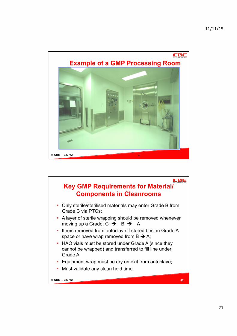
Example of a GMP Processing Room
41
© CBE – 023 V2
Key GMP Requirements for Material/Components in Cleanrooms
Only sterile/sterilised materials may enter Grade B from Grade C via PTCs;
A layer of sterile wrapping should be removed whenever moving up a Grade; C B A
Items removed from autoclave if stored best in Grade A space or have wrap removed from B A;
HAO vials must be stored under Grade A (since they cannot be wrapped) and transferred to fill line under Grade A
Equipment wrap must be dry on exit from autoclave; Must validate any clean hold time
42
11/11/15
22
© CBE – 023 V2
Pass Through Cabinets (PTCs)
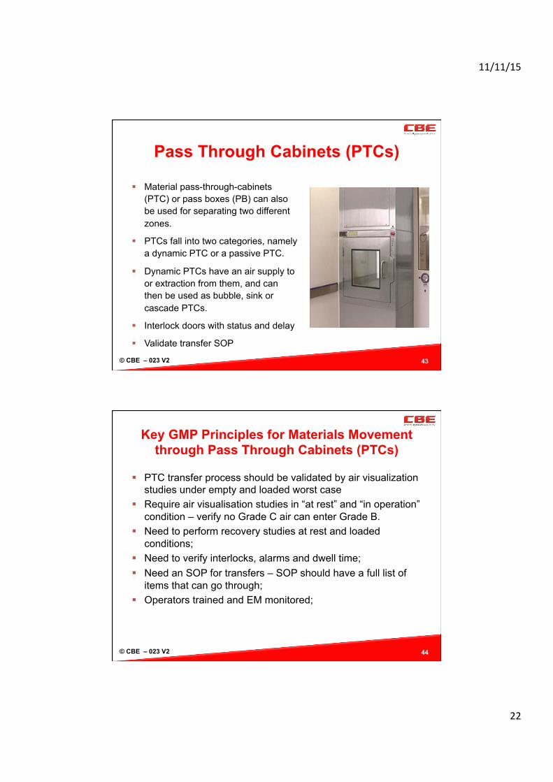
Material pass-through-cabinets (PTC) or pass boxes (PB) can also be used for separating two different zones.
PTCs fall into two categories, namely a dynamic PTC or a passive PTC.
Dynamic PTCs have an air supply to or extraction from them, and can then be used as bubble, sink or cascade PTCs.
Interlock doors with status and delay
Validate transfer SOP
43
© CBE – 023 V2
Key GMP Principles for Materials Movement through Pass Through Cabinets (PTCs)
PTC transfer process should be validated by air visualization studies under empty and loaded worst case
Require air visualisation studies in “at rest” and “in operation” condition – verify no Grade C air can enter Grade B.
Need to perform recovery studies at rest and loaded conditions;
Need to verify interlocks, alarms and dwell time; Need an SOP for transfers – SOP should have a full list of
items that can go through; Operators trained and EM monitored;
44
11/11/15
23
© CBE – 023 V2
Personal Air Locks (PALs) and Gowning
Gowning is a 3 grade transition Grade - D C B with transition interfaces
Doors should be interlocked and alarmed to preserve pressure
Limit the number of personnel in any one space Exit should ideally be via separate route or door HEPAs should be located on inner side up high of PAL and
returns on outer side down low For Material Air Locks (MALs) should be divided with
different trolleys used on each side of the crossover zone. No cross over of staff – proceduralised and closely monitored
45
© CBE – 023 V2 46
Operator gowning qualification for aseptic manufacture
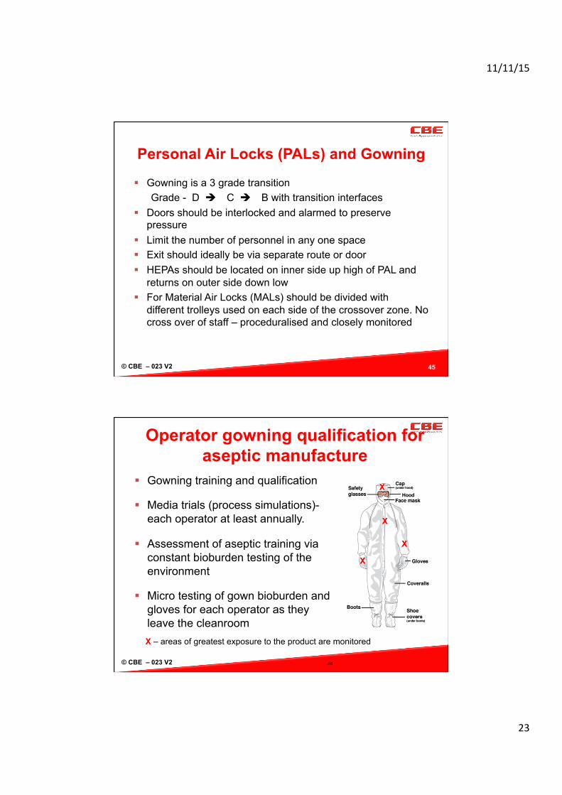
Gowning training and qualification
Media trials (process simulations)- each operator at least annually.
Assessment of aseptic training via constant bioburden testing of the environment
Micro testing of gown bioburden and gloves for each operator as they leave the cleanroom
X
X
X
X
X – areas of greatest exposure to the product are monitored
11/11/15
24
© CBE – 023 V2
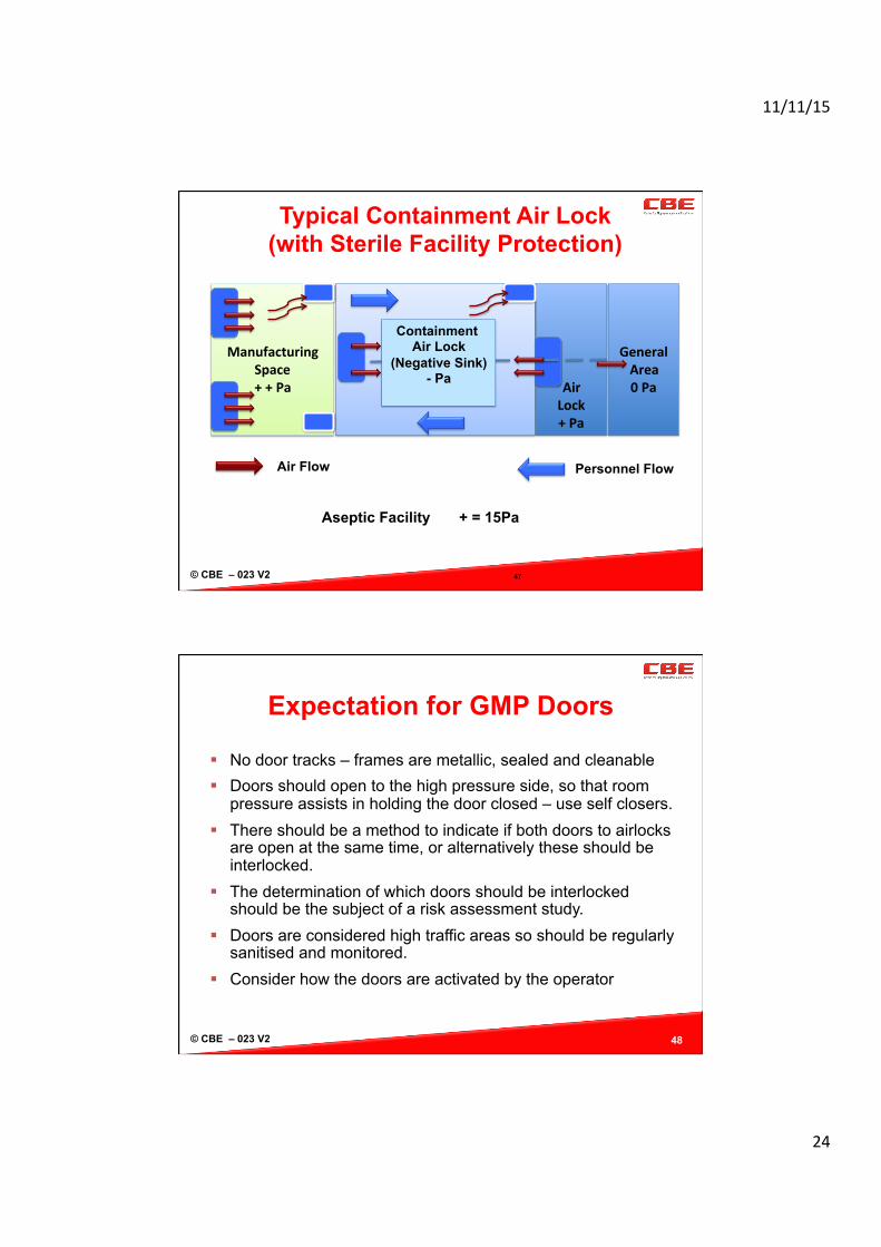
Air Lock + Pa
Manufacturing
Space + + Pa
General Area 0 Pa
Aseptic Facility + = 15Pa
Containment Air Lock
(Negative Sink) - Pa
47
Typical Containment Air Lock (with Sterile Facility Protection)
Personnel Flow Air Flow
© CBE – 023 V2
Expectation for GMP Doors
No door tracks – frames are metallic, sealed and cleanable Doors should open to the high pressure side, so that room
pressure assists in holding the door closed – use self closers. There should be a method to indicate if both doors to airlocks
are open at the same time, or alternatively these should be interlocked.
The determination of which doors should be interlocked should be the subject of a risk assessment study.
Doors are considered high traffic areas so should be regularly sanitised and monitored.
Consider how the doors are activated by the operator
48
11/11/15
25
© CBE – 023 V2
Grade B and Grade A Space
Must conduct air visualisation studies for Grade A space using a written protocol;
Air flow and turbulence in “at rest” and simulated “in operation” conditions;
Identify critical surfaces and critical space in Grade A Simulate interventions and transfers B A Use the information to conduct risk assessment on
entries to Grade A and location of monitoring. Re-visualisation on any change and say every 3 years Grade A must have continuous particle monitoring Must have one probe adjacent to the filling station
49
© CBE – 023 V2
GMPs and Grade A Space
Capper must be separate remote station to fill line All aseptic connections must occur in grade A All aseptic connections must be validated. Glove printing of aseptic operators
After any aseptic connection; Post set up of machine Post any Grade A intervention Limit is none detected on 5 fingers
Must never work over the top of open components
50

11/11/15
26
© CBE – 023 V2
Aseptic Operator Dos and Donts
✗ Tear open bags ✗ Enter when you’re sick ✗ Touch face / skin ✗ Place forceps on machine ✗ Work over the top of critical surfaces ✗ Touch components with hands ✗ Sneeze! ✗ Stay in Grade A ✗ Ignore alarms
51
Be aware of body position at all times
Sanitise hands regularly Must sanitise pre entry to
Grade A Move slowly and controlled Wear eye goggles Cut open bags Place forceps in sterile
holders Stay out of Grade A as much
as possible Verify room pressures
© CBE – 023 V2
Cleanroom GMP Maintenance Programs
Operating and maintenance (O&M) manuals, schematic drawings, protocols and reports should be maintained as reference documents for any future changes and upgrades to the system. Pressure cascades, schematics and other specifications should be available.
There should be a planned preventive maintenance programme, procedures and records for the HVAC system. Records should be kept.
Maintenance should be inspected before back into service and should occur out of production hours.
HEPA filters should be changed either by a specialist, and then followed by installed filter leakage testing. Physically inspect HEPA surfaces for growth or damage Qualify suppliers and testers Review reports and any failures 52

11/11/15
27
© CBE – 023 V2 53
cGMP Citations - Air Control HEPA integrity testing is deficient in that LAF velocity
measurements are not taken within 6” of the work surface. Lack of acceptance criteria defining leakage as % of the
challenge agent. Smoke studies on laminar air flows fail to ensure airflow is
laminar. Smoke studies of the HEPA’s in front of the lyophilisers are
not performed with the lyophiliser doors open. The pressure differentials between the class D gowning room
and the non-classified entry way are not monitored to ensure that the classified areas obtain and maintain an acceptable level of positive pressure relative to the surrounding areas.
© CBE – 023 V2 54
FDA 483s for HVAC and Air Handling
The daily differential air pressure records are not reviewed by a second responsible individual for completeness and accuracy.
There is no record to document the actual filter integrity readings that are obtained for the HEPA filter integrity testings to assure that the <0.003% penetration is achieved.
Magnehelic gauges that are used to monitor that the laminar air flow cabinets are not calibrated.
There have been no smoke studies performed for the aseptic filling area to assure that there is sufficient or suitable laminar air flow.

11/11/15
28
© CBE – 023 V2 55
FDA 483s for HVAC and air handling
The pressure differentials between the class x gowning room and the non-classified entry way, the class y areas and the surrounding support areas, are not monitored to ensure that the classified areas obtain and maintain an acceptable level of positive pressure relative to the surrounding areas.
The strip charts that record the pressure differentials between the aseptic filling room and the surrounding areas are not completely reviewed.
There is no written procedure that describes the course of events which are to be followed by the security guard during an alarm condition concerning the air pressure differentials or when there is a malfunction of the lyophilisers.
© CBE – 023 V2
Some Questions to Discuss
56 Revision

11/11/15
29
© CBE – 023 V2
Example HVAC Qualification Task List 1. URS and DQ signed off Company and HVAC Contractor 2. Clean ductwork and inspect ducts/seals Contractor / Company Witness 3. Attach HEPAs** and test / certify them in place Contractor / Company Witness 4. HVAC IQ Protocol and Report Contractor/ Company Witness 5. Balance System and Witness by Company*** Contractor/ Company Witness 6. Assess change over rates Contractor/Company approve 7. Checklist Rooms against Specifications Contractor/Company Witness 8. Final Clean of room to meet Grade – verify particles Contractor Fumigation / VHP/Ozonation ? 1. Check Temp. / RH% via BMS Contractor /Company Witness Handover to Company from Contractor 1. EMS Install and qualify Contractor / Company 2. Clean and Sanitise Cleanroom / Equipment Company issues SOPs 3. OQ Qualify “at rest” (Micro, Particles,Physical/air flow (3 X) Company: Production/Micro. Lab. 4. Clean/sanitise in between each OQ qualification Company Production 5. PQ - Micro, physical. particles “in operation” (concurrent with PV) Company QA/QC
** Need manufacturers certificates and serial numbers for each HEPA before they install them *** need to conduct post balance velocity measures through HEPAs as this is used for calculating room air change rates
57
© CBE – 023 V2
Physical Monitoring Requirements per PICs – Annex 1 and ISO 14644.
Environmental cleanliness - Airborne particles Pressure differentials between rooms >10 - 15Pa Air-change rates (>20) and recovery time (<15min) Uni-directional airflow velocities in Grade A – air visualisation Airflow patterns in Grade A – air visualisation studies Air filtration (final filters) requirements – generally HEPA
ISO 14644 – 1 Requirements Number particle samples per room: Square root of the
area of the clean-zone in m2, rounded up to nearest integer. Sample Size Calculation – ISO 14644-1 (Annex B)
58

11/11/15
30
© CBE – 023 V2
How often should HEPA filters and Cleanrooms be Re-Certified ?
ISO 14644 recommends frequency – Tighter the Grade the more frequent re-certification. (Grade A 6 months)
Need to be clear about “at rest” vs simulated “in operation” re-certification conditions
Locations of sampling points in room - need to be justified
# room samples is per ISO 14644 Airflow visualisation studies – maybe every 3 years and
certainly when considering any significant change to the room or equipment layout
59
© CBE – 023 V2
Alarming of Cleanrooms
60
Automated EMS monitoring systems enables Alarm Conditions to be recognised (Alerts & Actions).
Alarm Conditions
Separate alarms into “Critical” vs “Routine” – Need an SOP for responses
• Set to give early warning as we deviate from normal • Allows Ome to intervene and correct Ome before failure occurs ALERT
• Set to give warning that we have deviated from “validated state” ACTION

11/11/15
31
© CBE – 023 V2 61
Sterile Facility Exclusion Design - Cleanrooms
B
B
B
B A
A
A
C
C D
D C
C
C
C D
C
Grades A = 100 B = 10,000 C = 100,000 D = 100,000
C
© CBE – 023 V2 62
Sterile Facility Exclusion Design - Cleanrooms
B
B
B
B A
A
A
C
C D
D C
C
C
C D
C
Flows - Personnel
C
11/11/15
32
© CBE – 023 V2 63
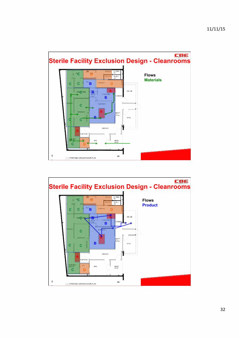
Sterile Facility Exclusion Design - Cleanrooms
B
B
B
B A
A
A
C
C D
D C
C
C
C D
C
Flows Materials
C
© CBE – 023 V2 64
Sterile Facility Exclusion Design - Cleanrooms
B
B
B
B A
A
A
C
C D
D C
C
C
C D
C
Flows Product
C

11/11/15
33
© CBE – 023 V2 65
Sterile Facility Exclusion Design - Cleanrooms
A
A
A
Grades HEPA – X Return low = **
C X XXX
** **
** X X
X X
X
X
**
X
X
**
** X
X
X
**
**
X
X **
X **
X **
X ** **
X ** ** X
© CBE – 023 V2
Case Study
Small group review of the cleanroom plan for the above layout.
1. Decide the product, materials and personnel flows 2. Decide appropriate locations of inlets and returns for each
cleanroom. 3. Decide how you would get the following into the facility
1. Vials 2. Stoppers 3. Caps 4. Personnel 5. Change parts 6. Chemicals for formulation 7. Movement of bulk product to the fill machine.
66

11/11/15
34
© CBE – 023 V2
Steve Williams, Director, CBE Pty Ltd www.cbe-ap.com.au +61(0)417116476 [email protected]