cbe417_notes_3_fa_2015_h
DESCRIPTION
CBE417_Notes_3_FA_2015_HTRANSCRIPT

CBE 417 CBE / SDSMT
CBE 417“Chemical Engineering Equilibrium
Separations”
1
Lecture Notes Set: 3

CBE 417 CBE / SDSMT
Overview
2
• Brief thermodynamics review• Binary Flash with material balance and energy balance
•Sequential solution•Simultaneous solution
• Multicomponent Flash• Flash Unit Operation (AspenPlus)• Staged systems• McCabe-Thiele

CBE 417 CBE / SDSMT
Constant Relative Volatility?
3
0
0.1
0.2
0.3
0.4
0.5
0.6
0.7
0.8
0.9
1
0 0.2 0.4 0.6 0.8 1
Y M
eOH
X MeOH
MeOH – water; 1 atm

CBE 417 CBE / SDSMT
Simulators
4
Flash input: MeOH – Water; 1.013 bar; ZMeOH=0.6; Find f to give XMeOH < 0.2
Sensitivity Analysis:
Design Spec:
AspenPlus Flash

CBE 417 CBE / SDSMT
PS Exercise: In-Class
5
Given mixture: n-pentane & n-hexane; 3 bar; ZC5=0.6; Let f = 0.35
1) By hand, using Txy and yx diagrams from class; find XC5 and YC5, and the flash operational temperature.
Follow-up questions:• What about Vfrac feed (effect)• What about PR vs NRTL
2) Repeat using AspenPlus.

CBE 417 CBE / SDSMT
In-Class AspenPlus Exercise
6
Flash input: Ethane – n-Heptane; ?? bar; Zethane = 0.5; Let f = 0.5 [make Txy and YX diagrams]
Sensitivity Analysis:
Design Spec:

CBE 417 CBE / SDSMT 7
Sensitivity Analysis:f varies 0.05 – 0.95
Row /
Case Status VFRAC YC2 XC2 1 0 0.05 0.997 0.4742 0 0.1 0.997 0.4453 0 0.15 0.996 0.4134 0 0.2 0.994 0.3765 0 0.25 0.991 0.3366 0 0.3 0.986 0.2927 0 0.35 0.975 0.2448 0 0.4 0.953 0.1989 0 0.45 0.913 0.16210 0 0.5 0.863 0.13711 0 0.55 0.810 0.12112 0 0.6 0.761 0.10813 0 0.65 0.716 0.09914 0 0.7 0.675 0.09215 0 0.75 0.638 0.08616 0 0.8 0.605 0.08117 0 0.85 0.575 0.07618 0 0.9 0.548 0.07219 0 0.95 0.523 0.069
feedinCmolproductinCmol
2
2Recovery
In-Class AspenPlus Exercise

CBE 417 CBE / SDSMT
Example:
8
Flash input: n-hexane – n-octane; 1.013 bar; Zhexane = 0.5; Let f = 0.5 Desire to obtain pure C6 & C8; 1st attempt using flash drum..

CBE 417 CBE / SDSMT
Example:
9
Single flash

CBE 417 CBE / SDSMT
Simulators
10
How increase overhead purity?

CBE 417 CBE / SDSMT
Simulators
11
How increase overhead purity?

CBE 417 CBE / SDSMT
Simulators
12
How increase overhead purity?

CBE 417 CBE / SDSMT
Simulators
13
How increase overhead purity?
CBE 417 CBE / SDSMT
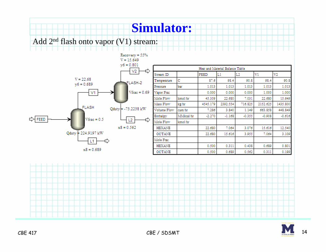
Simulator:
14
Add 2nd flash onto vapor (V1) stream:
CBE 417 CBE / SDSMT
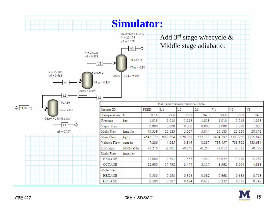
Simulator:
15
Add 3rd stage w/recycle &Middle stage adiabatic:

Cascade Flash Summary:
16
• Additional “flash” stages improve purity, but recovery is poor• Recycle of intermediate streams allows better recovery while
preserving good purity• Intermediate stages operated adiabatically – minimizing the
need for intermediate HX equipment, pumps, or valves• Heat provided in bottom stage provides vapor “boilup”• Heat removed from top stage provides liquid “reflux”• This allows for a cascade separation to be done in one piece of
equipment – called a distillation column

CBE 417 CBE / SDSMT
Top of “Column”
17
Rectifying (enriching) section of distillation
column

CBE 417 CBE / SDSMT
Equilibrium “Stage”
18
Liquid and vapor leaving a stage (tray) are assumed to be in
equilibrium

CBE 417 CBE / SDSMT
Bottom of “Column”
19
Stripping section of distillation column

CBE 417 CBE / SDSMT
Distillation Column
20

CBE 417 CBE / SDSMT
Example:
21
Flash input: n-hexane – n-octane; 1.013 bar; Zhexane = 0.5; Setup:• use RADFRAC block• saturated liquid feed• feed pressure 1 atm
• 20 equilibrium stages• total condenser• kettle reboiler• reflux ratio = 0.56• distillate to feed ratio = 0.5
• feed stream on stage 9• pressure in condenser = 1 atm

CBE 417 CBE / SDSMT
Distillation Column
22

CBE 417 CBE / SDSMT
Questions?
23

CBE 417 CBE / SDSMT
Extra notes; just for reference
24

CBE 417 CBE / SDSMT
Simulator:
25
Add 2nd flash with recycle:

CBE 417 CBE / SDSMT
Simulator:
26
Add 3rd stage flash with recycle:

CBE 417 CBE / SDSMT
Simulator:
27
Add 3rd stage w/recycle &Middle stage adiabatic & Higher “reflux” :

CBE 417 CBE / SDSMT
Cascade Summary:
28
Cascade Demo Summary TableFall 2012 C6 Heat Duty [kW]
Flash y out recovery reboiler condenser1 stage 0.69 69% 224.9
2 stages 0.80 55% 224.9 -73.2
2 stg w recycle 0.79 64% 267.3 -86.8
3 stg w recycle 0.83 64% 276.1 -104.7
3 stg w recycle & Q2 = 0 0.758 67% 250.9 -52.9
" " w/higher "reflux" 0.856 65% 282.3 -117.2
CBE 417 CBE / SDSMT
Cascade Flash Summary:
29
• Method to improve vapor purity of light “key” component• Improve overall recovery of light key by recycling liquid from
stages above to previous stage• Not practical to have intermediate HX or pump between each
flash stage• Assemble stages in vertical column where vapor flows up to
next stage, and liquid flows down to stage below.• Preheat feed (Qin) and remove heat at top condenser (Qcond).• Intermediate stages adiabatic• Liquid recycle “enriches” vapor in “lighter” component• Effect enhanced as total liquid recycle flow is increased.
Aside: Key components (LK, HK) define where split is to be made.Most of LK in top stream; most of HK in bottom stream

CBE 417 CBE / SDSMT 30
Add 3rd stage w/recycle &Middle stage adiabatic & Higher “reflux” & With stage below and recycle:

CBE 417 CBE / SDSMT
Cascade Summary:
31
Cascade Demo Summary TableSS 2010 C6 Heat Duty [kW]
Flash y out recovery reboiler condensor1 stage 0.69 69% 224.9
2 stages 0.80 55% 224.9 -73.2
2 stg w recycle 0.79 64% 267.3 -86.8
3 stg w recycle 0.83 64% 276.1 -104.7
3 stg w recycle - Q2 = 0 0.758 67% 250.9 -52.9
" " w/higher "reflux" 0.856 65% 282.3 -117.2
" " " and stage below 0.814 89% 420.2 -171.6

CBE 417 CBE / SDSMT 32
Add 3rd stage w/recycle &Middle stage adiabatic & Higher “reflux” & With stage below and recycleAnd adiabatic Flash by feed:

CBE 417 CBE / SDSMT
Cascade Flash Summary:
33
• Additional “flash” stages improve purity, but recovery is poor• Recycle of intermediate streams allows better recovery while
preserving good purity• Intermediate stages operated adiabatically – minimizing the
need for intermediate HX equipment, pumps, or valves• Heat provided in bottom stage provides vapor “boilup”• Heat removed from top stage provides liquid “reflux”• This allows for a cascade separation to be done in one piece of
equipment – called a distillation column

CBE 417 CBE / SDSMT
Questions?
34