cc 305 - cc 335 - cc 355 - valeo.datasystemweb.com.br
TRANSCRIPT
Rev.05 - November 2020Code: 036-00196-003
Owner’s ManualWarranty Certificate
CC 305 - CC 335 - CC 355
AIR CONDITIONER COACHBUS - CITY BUS
1

INDEX CC 305 - CC 335 - CC 355
OBSERVATION: to get the best air conditioner performance we recommend that you read this manual carefully before starting operation.Keep this manual with your vehicle for reference.
INTRODUCTION______________________________________________________________________________________________________________________________________________________3WARRANTY TERMS
Warrant Terms__________________________________________________4
PREVENTIVE MAINTENANCEPreventive Maintenance Frequency Check List_________________________5Refrigerant Gas R134a_________________________________________6Dry Filter_____________________________________________________6Compressor Sealing Part______________________________________________6Heating System___________________________________________6Oil___________________________________________________________6Ducts______________________________________________________________________6Pulley Belts_______________________________________________________6
EQUIPMENT IDENTIFICATION (ID)Identification Tag______________________________________________7
OPERATING THE AIR CONDITIONER1- Operating the Air Conditioner_____________________________________________________82- SBU 400-410 Controllers___________________________________________102.1- Control Panel Description_______________________________________________________102.2- Operation Instructions_______________________________________________________________________________________________112.3- Auto Mode_________________________________________________________________112.4- ON/OFF Air Conditioner Compressor___________________________________________122.5- Heating Mode__________________________________________________________122.6- Desired temperature level SET POINT________________________________122.7- Evaporator fan speed configuration_________________________________________132.8- Enabling / Disabling the ventilation function__________________________________________132.9- Faults (errors)________________________________________________________14
EQUIPMENT DESCRIPTION3- Technical Data Sheet________________________________________153.1- Evaporator Components____________________________________________________163.2- Condenser Components_____________________________________________________173.3- Compressor Components - BOCK FKX 40/655K___________________________________________________183.4- Compressor Components -TM 65___________________________________________________193.5- Electric Components________________________________________________20
ELECTRICAL SYSTEM4- Controller SBU400/410_____________________________________________21
SAFETY PRECAUTION5- Safety Precaution..................................................................................................................................................................................................................................................................22
SUSTAINABILITY6- Product Discard_____________________________________________________________________24
INTRODUCTION
VALEO Climatização do Brasil - Veículos Comerciais S/A offers a full line of equipment for bus air conditioning systems for vans, micro and midi buses, commuter, articulated, coaches and double-deckers.
Air conditioning system that is modern and high quality, the products of VALEO Climatização do Brasil - Veículos Comerciais S/A have been developed looking for comfort and tranquility to passengers that uses the public transport.
However, you need to take care to assure a good use and operation of the air conditioning system, and then you can obtain a better performance of its technology resources.
It is mandatory to do the preventive and corrective maintenance procedures, they must be accomplished by experts or dully technicians. Looking for improving and updating the refrigeration technical teams, this manual describes the fundamentals of our air conditioning system based on the most important thermodynamic formulas.
You can find operation instructions of VALEO Climatização do Brasil - Veículos Comerciais S/A air conditioning too, besides it advises you to follow technical procedures of adequate preventive maintenance obeying environmental and safety rules.
Frequent training for technical team make them able to get right diagnosis from equipment (appliances) to accomplish the servicing.
correctly with quality and responsibility, assuring to the whole fleet a perfect operation of VALEO Climatização do Brasil - Veículos Comerciais S/A equipment.
CC 305 - CC 335 - CC 355
3
WARRANTY TERMS
Warrant Terms
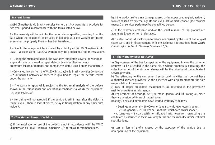
VALEO Climatização do Brasil - Veículos Comerciais S/A warrants its products for two-years period in accordance with the terms listed below:
1 - The warranty will be valid for the period above specified, counting from thedate when the equipment is installed in keeping with the warrant certificate, even after the property there of has ben transfered.
2 – Should the equipment be installed by a third part, VALEO Climatização do Brasil - Veículos Comerciais S/A warrant only the product and not its instalations.
3 - During the stipulated period, the warranty completely covers the workman-ship and spare parts used to repair defects duly identified as being:premature failure of material and components defects used on its manufacture.
4 - Only a techinician from the VALEO Climatização do Brasil - Veículos Comerciais S/A authorized network of services is qualified to repair the defects coverd under the warranty.
5 - The warranty approval is subject to the technical analysis of the defects shown in the components and operational conditions to which the equipment has been subjected.
6 - No claims will be accepted if the vehicle is still in use after the defect is found, even if there is lack of pieces, delay in transportation or any other such incident.
b) If the product suffers any damage caused by improper use, neglect, accident, failures caused by external agents and even lack of maintenance (see owner's manual) or services performed by unqualified person.
c) If the warranty certificate and/or the serial number of the product are adulterated, overwritten or damaged.
d) If defects or unsatisfactory performance are caused by the use of non originalspare parts and in disagreement with the technical specifications from VALEO Climatização do Brasil - Veículos Comerciais S/A.
8 - The Warranty Does Not Cover
a) Displacement of the bus for repairing of the equipment. In case the customerrequests to be attended in the same place where products is operating, the collection or not of the visitation charge will be the criterion of the authorized service provider.b) The attending to the consumer, free or paid, in cities that do not have authorized services providers. So the expenses with displacement are the sole responsibility of the owner.c) Lack of proper preventive maintenance, as described in the preventive maintenance item in this manual.d) Replacement of bearings, belts, filters in general and lubricating oil, since they are considered items of natural wear.Bearings, belts and alternators have limited warranty as follows:
- Bearings in general = 60,000km or 2 years, whichever occurs sooner. - Belts in general = 20,000km or 3 months, whichever occurs sooner. - Alternators = 2 years with no mileage limit, however, respecting the conditions established in these warranty terms and the manufacturer's technical specifications.
e) Loss or loss of profits caused by the stoppage of the vehicle due to non-operation of the equipment.
7 - The Warrant Loses its Validity
a) If the installation or use of the product is not in accordance with the VALEO Climatização do Brasil - Veículos Comerciais S/A technical recommendations.
CC 305 - CC 335 - CC 355
4
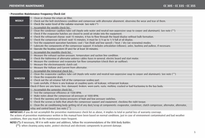
- Preventive Maintenance Frequency Check List
PREVENTIVE MAINTENANCE CC 305 - CC 335 - CC 355
1 - Clean or change the return air filter.2 - Check out the belt stretchiness condition and compressor with alternator alignment, observing the wear and tear of them.3 - Check the water level of the radiator reservoir. See note (*)1 - Accomplish the weekly check list.2 - Clean the condenser capillary tube coil (Apply only water and neutral non-aggressive soup to cooper and aluminum). See note (**)3 - Check if the evaporator hatches are closed to avoid air intake into the equipment.4 - Check the refrigerant charge: wait 15 minutes, it has to flow through the liquid display without bulb formation.5 - Check the compressor oil level: wait 15 minutes, it must be 3/4 up to 1/4 full at oil display.6 - Test the equipment operation functions: cool / fan (high and low speed) / heat / dry (air renewing) modes.7 - Lubricate the components of the compressor support. It includes articulation (elbows), axles, bushing and pulleys, if necessary.8 - Operate the heating system (if any) for at least 30 minutes.1 - Accomplish the monthly check list.2 - Measure the exhaust suction pressure, temperature and suction line condition.3 - Check the tightening of alternator potency cables fuses in general, electric board and start motor.4 - Measure the condenser and evaporator fan flow consumption (check their air outflow).5 - Measure the electromagnetic clutch coil.6 - Measure the Voltage and Current from alternator.1 - Accomplish the trimestral check list.2 - Clean the evaporator capillary tube coil (Apply only water and neutral non-aggressive soup to cooper and aluminum). See note (**)3 - Clean the evaporator drain.4 - Check out the oil retainer felt of the compressor sealing part.5 - Look carefully, if there is any leakage at coupling spots: oil leakage, refrigerant leakage.Check if there are any loose, free, damaged, broken, worn parts, rusty, melting, cracked or bad fractioning to the bus body.1 - Accomplish the semester check list.2 - Test the compressor efficiency at 1500 RPM.3 - Make notes about the compressor oil pressure at 1000 RPM.4 - Check the opening and closing pressures of high and low pressure switches.5 - Check the screws or bolts that attach the compressor support and equipment, checking the right torque.6 - Clean the air conditioning body getting rid of any dust/scrap at components: evaporator, condenser, clutch compressor, alternator, alternator, relay and control board. See note (**)
IMPORTANT: If you do not accomplish the preventive maintenance check list as above, it implies to total or partial loss of warranty coverage.
(**): when cleaning using water, protect electrical and electronic components to prevent damage.
The actions of preventive maintenance written in this manual have been based on normal conditions. Just in case of environment contaminated and bad weather conditions, then you must do the maintenance more frequent.
WEEKLY
MONTHLY
NOTES (*): if necessary, fill it in with water and additives, follow the recommendations of the OEM Body Builder.
YEARLY
SEMESTER
TRIMESTRAL
5

SAY NO TO RECONDITIONED PARTS
ATTENTION: under no circumstances, refrigerant cannot be spoiled at theatmosphere.
IMPORTANT: check reservoir water level. If necessary, fill it in with waterand additives, follow the recommendations of the OEM Body Builder.
PREVENTIVE MAINTENANCE
- Refrigerant Gas R134a
VALEO Climatização do Brasil - Veículos Comerciais S/A products apply for R 134a. The se of different type of gas, low quality or from unknown brands will cause low performance from the refrigeration and damage the equipment components. - Ducts
The cleaning of the air ducts must be done every tree months, it can be earlier, depending on: the frequency of operation of the air conditioning system, quantity of passengers and resistivity of the environment where it is driven. This cleaning is the responsibility of the vehicle owner´s only, he is in charge of this cleaning in order to offer good air quality to his passengers.
NOTE: ducts are components of the bus body.
- Pulley Belts
In order to increase the lifetime of the belts, the strength/stretchiness must be as low as possible, but working, not leaving them skidding without any friction.Too low stretchiness on the pulley belts can cause overheat and too much skidding, causing early break.Too much stretched belts diminish their lifetime and from roll bearing and from sleeves, this problem can cause engine interior and compressor damage.After changing the belts, check their stretchiness back again after 48 working hours.It is recommended not use different brands. Install assemblies with the same diameter/length of the series and do not apply new belts beside old ones. Putting the assembly into action without one or two belts for a long time can cause a damage inside the “v” groove of the pulley. It will cause wear in that “v” groove, so the new belt may not be stretched accordingly.
The application of reconditioned parts will diminish the air conditioning efficiency, will overcharge the electric system causing early brake of the compressor and set a fire!
- Oil
We recommend you that you shall preventively change the air system oil every two years or 10.000 working hours, whatever becomes first.
- Dry Filter
We recommend that you shall preventively change the drier filter every 3 years. Just in case, you need to refill in the equipment with gas, we recommend you replace to a new filter to extinguish any dirt out of the system.
- Heating system
We recommend that you enable the heating system frequently (once a month) to prevent the buildup of solid system particles that lodge in the hot air shutoff valve seat.
- Compressor Sealing Part
In order to avoid leakage at the sealing part of the compressor due to lack of lubrication, then the air conditioning must be working at cool mode for at least 15 minutes, once every 15 days.The sealing part is lubricated by the compressor oil and in its normal operation allows a small leakage of 0.05 ml per hour under operation.Check frequently the reservoir and/or felt then remove the excess of it.Dispose the old oil as your Country regulations and laws.
CC 305 - CC 335 - CC 355
6
PREVENTIVE MAINTENANCE - EQUIPMENT IDENTIFICATION (ID)
ATTENTION: Just in case a problem happens in the refrigeration system, then it must be repaired in an authorized shop or qualified professional.If a third party installs the equipment, VALEO Climatização do Brasil - Veículos Comerciais S/A, guarantees only the product, not the installation of it.
The following items are in charge of the OEM Plant (Bus Body Builder).
• Driver´s evaporator:Problems with any driver´s air conditioning component, leakage, bad working or operation.IMPORTANT: lclean the return filter of the driver´s air conditioning, at least, once a week.
• Tubes, hoses, drains and wiring harness:Bad attachment. Leakage at connections and welding points. Damages due to frictioning / chassis and components frictioning or bad installed.
• Alternator/Compressor Support:Excess or lack of torque at attaching screws/bolts. Assembly is out of project designs. Pulleys are not aligned, excess or lack of stretchiness at the belts and pulleys.• Gas Charge Process:
Leakage test procedure. Vacuum process and refrigerant gas charge.
Note: in case the installation is bad, VALEO Agent Authorized Service Net will have to call the OEM Plant first, then get an authorization to do the service,print and issue the Invoice of repairs.
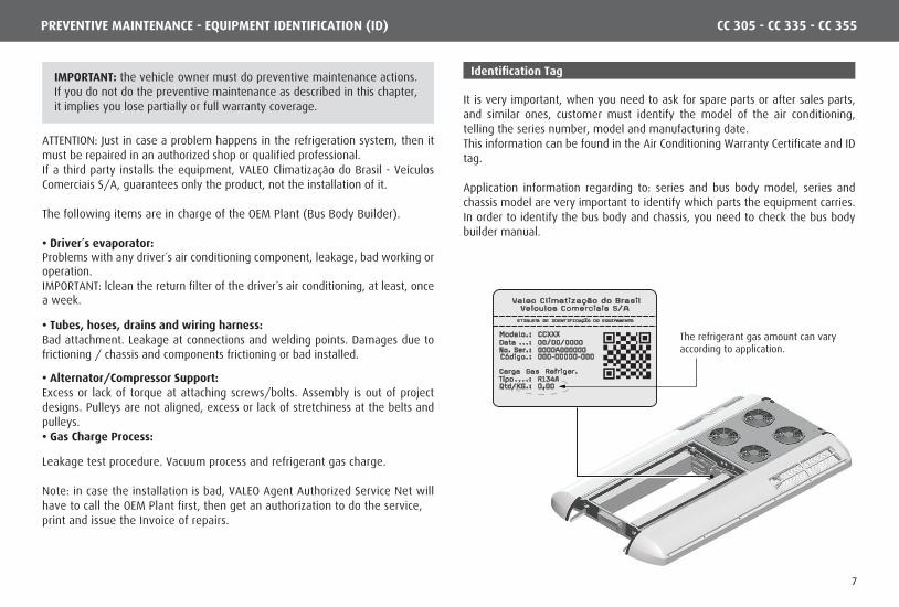
Identification Tag
It is very important, when you need to ask for spare parts or after sales parts, and similar ones, customer must identify the model of the air conditioning, telling the series number, model and manufacturing date.This information can be found in the Air Conditioning Warranty Certificate and ID tag.
Application information regarding to: series and bus body model, series and chassis model are very important to identify which parts the equipment carries.In order to identify the bus body and chassis, you need to check the bus body builder manual.
The refrigerant gas amount can varyaccording to application.
CC 305 - CC 335 - CC 355
IMPORTANT: the vehicle owner must do preventive maintenance actions. If you do not do the preventive maintenance as described in this chapter, it implies you lose partially or full warranty coverage.
7
OPERATING THE AIR CONDITIONER
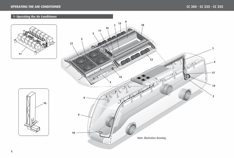
1- Operating the Air Conditioner
Note: illustrative drawing.
17
14
28
1
167
15
6
13
11
13
5
4
3
12
18
9
9
10
16
11
CC 305 - CC 335 - CC 355
8
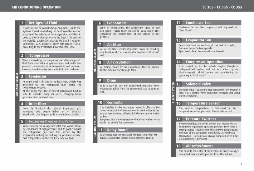
Condenser FanCondenser fan and the compressor will only work at “Cool Mode”.
Refrigerant Fluid
Its main goal is dissipate the heat out, which was absorbed by the refrigerant fluid along the refrigeration system. At the condenser, the overheat refrigerant fluid is sent to outside losing its force, changing from gaseous state to liquid state.
Condenser
Drier filterTiene la finalidad de retener impurezas y/o humedad que pueda haber en el sistema impidiendo que lleguen en la válvula de expansión.
Valve hinders the refrigerant inlet that comes from de condenser at high pressure and its goal is adjust the refrigerant gas flow that passed by the evaporator looking for making the pressure steady and temperature at the capillary tubes output.
CompressorWhen it is working, the compressor sucks the refrigerant fluid from evaporator at gaseous state and under low pressure, compressing it, so temperature and pressure increase, then the compressor puts it into the condenser.
MEC
HA
NIC
SYS
TEM
Compressor OperationIt is started up by the vehicle engine though a pulley-and-belt system and put into action by an electromagnetic clutch when air conditioning is operating at “Cool Mode”.
Air refrechmentThis permits the entry of the exernal in order to expelunwanted odors and impurities from the vehicle.
Evaporator FanEvaporator fans are working at cool and fan modes, fans can be set in two speeds. Sped control can be manual or automatic.
Temperature SensorThe interior temperature is measured by the temperature sensor placed at the air return spot.
Pressure SwitchesPressure switches are electric devices that monitor the air conditioning equipment operation pressure. Every time a strong change happens from the NORMAL temperature, they turn off the compressor immediately to avoid break.Observation: pressures are always monitored, even if the air conditioning is turned off.
ELEC
TRIC
SYS
TEM
EvaporatorsNow at evaporators, the refrigerant fluid, at low pressure, turns from l iquid to gaseous state, absorbing the interior heat of the vehicle in this process.
ControllerIt is installed in the instrument panel, it offers to the driver to set-point of temperature, to see by display the interior temperature, offering full climatic control inside de bus.Set-point: it is the temperature the driver wishes to set inside the vehicle for passengers.
Relay BoardRelay board has the controller controls, condenser fan control, evaporator control and compressor control.
Air filterAir return filter retains impurities from air avoiding any block of dirt at evaporator capillary tubes and coil.
Air circulationAir being cooled by the evaporator, then it follows to the bus interior through fans.
DrainIt is a way to get the condensed moisture from evaporator tubes from the condensed tray to putting out.
MEC
HA
NIC
SYS
TEM
ELEC
TRIC
SYS
TEM
1
2
3
4
5 Expansion Thermostatic Valve
6
7
8
9
10
11
18
12
13
14
16
Solenoid Valve15
17
Solenoid valve is applied to stop refrigerant flow through a line. It is a closing valve controlled remotely and under electric operation.
CC 305 - CC 335 - CC 355AIR CONDITIONING OPERATION
It is inside the air conditioning equipment, inside the system. It works absorbing the heat from the interior / room of the vehicle, at the evaporator, and then it goes to the condenser where the heat is thrown to the outside. VALEO Climatização do Brasil - Veículos Comerciais S/A, products apply refrigerant R134a, according to the Protection Environmental Law.
9
CONTROLLERS
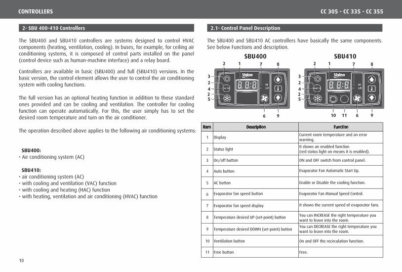
The SBU400 and SBU410 controllers are systems designed to control HVAC components (heating, ventilation, cooling). In buses, for example, for ceiling air conditioning systems, it is composed of control parts installed on the panel (control device such as human-machine interface) and a relay board.
Controllers are available in basic (SBU400) and full (SBU410) versions. In the basic version, the control element allows the user to control the air conditioning system with cooling functions.
The full version has an optional heating function in addition to those standard ones provided and can be cooling and ventilation. The controller for cooling function can operate automatically. For this, the user simply has to set the desired room temperature and turn on the air conditioner.
The operation described above applies to the following air conditioning systems:
SBU400:• Air conditioning system (AC)
SBU410:• air conditioning system (AC)• with cooling and ventilation (VAC) function• with cooling and heating (HAC) function• with heating, ventilation and air conditioning (HVAC) function
The SBU400 and SBU410 AC controllers have basically the same components. See below Functions and description.
2- SBU 400-410 Controllers 2.1- Control Panel Description
SBU400 SBU4101
3
9
8
5
42
6
72
23
5
42
2
2
1
9
8
6
7
10 11
Item Description Function
1 DisplayCurrent room temperature and an errorwarning.
2 Status lightIt shows an enabled function(red status light on means it is enabled).
3 On/off button ON and OFF switch from control panel.
4 Auto button Evaporator Fan Automatic Start Up.
5 AC button Enable or Disable the cooling function.
6 Evaporator fan speed button Evaporator Fan Manual Speed Control.
7 Evaporator fan speed display It shows the current speed of evaporator fans.
8 Temperature desired UP (set-point) button You can INCREASE the right temperature youwant to leave into the room.
9 Temperature desired DOWN (set-point) buttonYou can DECREASE the right temperature youwant to leave into the room.
10 Ventilation button On and OFF the recirculation function.
11 Free button Free.
CC 305 - CC 335 - CC 355
10

in Standby
Attention: if the return (back) temperature is below the desired room temperature, then the device enables the heating system automatically (SBU410 only) and outputs to the floor convector solenoids.
Note: SBU410 is shown to show several versions in general. Note: when device is started up, auto starts ON (Its status light becomes ON).
Automatic ventilation is controlled by the Set Point along with P16 and P18 parameters, according to table below.
At Heating Mode, the evaporator speed is always LOW.
Note: when you enable Auto mode, then system controls evaporator fans automati-cally. Pressing the Auto button again, then it shuts off the evaporator fans automati-cally.
- Standby: if the alternator warning lamp signal (KL.61) is disabled (this indicates that the vehicle or air-conditioner alternator is operating correctly and the battery voltage at the terminal plug can be measured), then system will be in standby mode. ON / OFF button status LED lights up in red.
Press button (2) when the status light is OFF. Auto mode will start and the corresponding status light will become on.
2.2- Operation Instructions
• Enabling/Disabling Standby Mode
• Enabled
2.3- Auto Mode
1
1
Display after enabling
- Disable: press button (1).The Compressor and fans are immediately disabled (the same will occur if the KL.61 signal is enabled). If the KL.61 signal is disabled, the device goes into Standby and the ON / OFF button status light illuminates red.
- Enable: press button (1).The status led for the ON/OFF button goes out. The return (back) temperature will appear when starting the controller for the first time. The AUTO mode and AC button are enabled, so it is controlling the speed of the evaporator fans automatically.
22.0
2
Before and after Auto Mode Enabling.
22.0
22.0
Temperaturedecreasing
Set-point
Temperatureincreasing
High Speed
Low Speed
Set-point + P16
(Set-point + P16) - P18
CONTROLLER CC 305 - CC 335 - CC 355
11
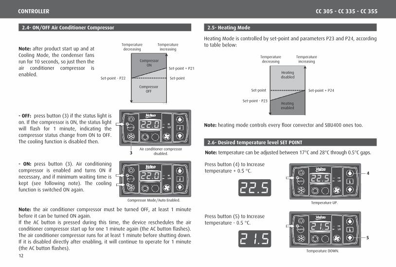
Note: temperature can be adjusted between 17°C and 28°C through 0.5°C gaps.
Note: heating mode controls every floor convector and SBU400 ones too.
Note: the air conditioner compressor must be turned OFF, at least 1 minute before it can be turned ON again.If the AC button is pressed during this time, the device reschedules the air conditioner compressor start up for one 1 minute again (the AC button flashes).The air conditioner compressor runs for at least 1 minute before shutting down. If it is disabled directly after enabling, it will continue to operate for 1 minute (the AC button flashes).
Note: after product start up and at Cooling Mode, the condenser fans run for 10 seconds, so just then the air conditioner compressor is enabled.
2.5- Heating Mode2.4- ON/OFF Air Conditioner Compressor
2.6- Desired temperature level SET POINT
3Air conditioner compressor
disabled.
- OFF: press button (3) if the status light is on. If the compressor is ON, the status light will flash for 1 minute, indicating the compressor status change from ON to OFF. The cooling function is disabled then.
Press button (4) to Increasetemperature + 0.5 °C.
Press button (5) to Increasetemperature - 0.5 °C.
22.0
Compressor Mode/Auto Enabled.
- ON: press button (3). Air conditioning compressor is enabled and turns ON if necessary, and if minimum waiting time is kept (see following note). The cooling function is switched ON again.
22.0
Temperature UP.
22.5
22.5
2 1.5
4
Temperature DOWN.
2 1.55
Temperaturedecreasing
Set-point
Temperatureincreasing
CompressorON
CompressorOFF
Set-point - P22
Set-point + P21
Temperaturedecreasing
Set-point
Temperatureincreasing
Heatingenabled
Heatingdisabled
Set-point - P23
Set-point + P24
Heating Mode is controlled by set-point and parameters P23 and P24, according to table below:
CONTROLLER CC 305 - CC 335 - CC 355
12
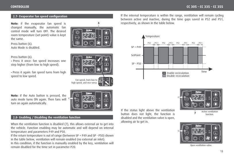
Note: if the evaporator fan speed is changed manually, the automatic fan control mode will turn OFF. The desired room temperature (set point) value is kept the same.
Note: if the Auto button is pressed, the auto mode turns ON again. Then fans will turn on again automatically.
2.7- Evaporator fan speed configuration
2.8- Enabling / Disabling the ventilation function
6
Fan speed, from low tohigh speed, and vice-versa.
Active ventilationfunction.
Press button (6).Auto Mode is disabled.
When the ventilation function is disabled (7), this allows external air to get into the vehicle. Function enabling may be automatic and will depend on internal temperature and parameters P49 and P50. If the return temperature is out of range (between SP + P49 and SP - P50) shown in the table below, ventilation will remain enabled (no external air inlet). In this condition, if the function is manually enabled by the key, ventilation will remain disabled for the time set in parameter P20.
If the internal temperature is within the range, ventilation will remain cycling between active and inactive, during the time gaps saved in P52 and P51, respectively, as shown in the table below.
If the status light above the ventilation button does not light, the function is disabled and the ventilation valve is open, allowing air to get in.
Press button (6).• Press it once: fan speed increases one step higher (from low to high speed).
• Press it again: fan speed turns from high speed to low speed.
22.0
22.0
22.0 22.0
7
Open ventilation valve.
22.0
22.0
Temperature
TimeEnable recirculation Disable recirculation
SP + P49 -
SetPoint
SP - P50 -
P51 P51 P51 P51P52 P52 P52 P52
CONTROLLER CC 305 - CC 335 - CC 355
13

2.9- Faults (errors)
Display failure.
F 0 0Note: if there is a fault, the display goes between Set point and the error codes. The desired temperature will be displayed for 5 seconds and the error series (s) occurring will be displayed for 2 seconds each. If an error has been eliminated, it will no longer be displayed.
• Display Failure
Error Component Cause Solution
F00Low or HighPressure Switch
Refrigerant gas level is wrong.Press switch is faulty.Expansion valve is faulty.Condenser is blocked or faulty.
Change the press switch and/or compressor.Check the condenser fans.Check the refrigerant gas level.Look for any leaks.Change the expansion valve.
F01Feed source(relay board)
Feed input is out of limit:12V: <10V >16V 24V: <20V >32V
Check the wiring harness.Change the relay board.
F02Feed source(control panel)
Feed input is out of limit:12V: <10V >16V 24V: <20V >32V
Check the wiring harness.Change the relay board.
F03 System type No recognition, no link. Change the controller.
F04Return (back)temperaturesensor
Ground short circuit troublebetween pins.
Check the wiring harness.Change the sensor.
F05Return (back)temperaturesensor
Ground short circuit troublebetween pins.
Check the wiring harness.Change the sensor.
F06Duct temperaturesensor (SBU410)
Power (+) short circuit ortrouble between sensor.
Check the wiring harness.Change the sensor.
Error Components Cause Solution
F07Duct temperaturesensor (SBU410)
Ground short circuit troublebetween pins.
Check the wiring harness.Change the sensor.
F08 EEPROM No access from EEPROM. Change the controller.
F09Motor watermeasuring valve(SBU410)
It can not be adjusted at theright pressure.
Check the wiring harness.Change the motor.
F10Compressor clutchcoupling
F00 has appeared for 3 timesor more. See F00.
CONTROLLER CC 305 - CC 335 - CC 355
14
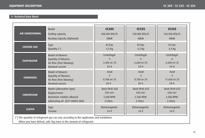
3- Technical Data Sheet
Model CC305 CC335 CC355
Cooling capacity 108.000 BTU/h 120.000 BTU/h 136.500 BTU/h
Heating Capacity (Optional) 40kW 40kW 40kW
Type R134a R134a R134a
Quantity (*) 4,3 Kg 4,3 Kg 4,3 Kg
Model of blowers Centrífugal Centrífugal Centrífugal
Quantity of blowers 4 6 6
Air flow (free blowing) 4.400 m³/h 6.600 m³/h 6.600 m³/h
Nominal current 36 A 54 A 54 A
Model of blowers Axial Axial Axial
Quantity of blowers 3 3 4
Air flow (free blowing) 8.700 m³/h 8.700 m³/h 11.600 m³/h
Nominal current 26 A 26 A 34 A
Model (alternative type) Bock FK40 560 Bock FK40 655 Bock FK40 655
Displacement 554 cm³ 650 cm³ 650 cm³Maximum rotation allowed 3.500 RPM 3.500 RPM 3.500 RPM
Lubricating oil (027-00002-000) 2 Liters 2 Liters 2 Liters
Type Eletromagnetic Eletromagnetic Eletromagnetic
Tension 24 V 24 V 24 V
(*) The quantity of refrigerant gas can vary according to the application and installation.
When you have defrost, add 1kg more in the amount of refrigerant.
CONDENSER
CLUTCH
AIR CONDITIONING
COOLING GAS
EVAPORATOR
COMPRESSOR
CC 305 - CC 335 - CC 355EQUIPMENT DESCRIPTION
15
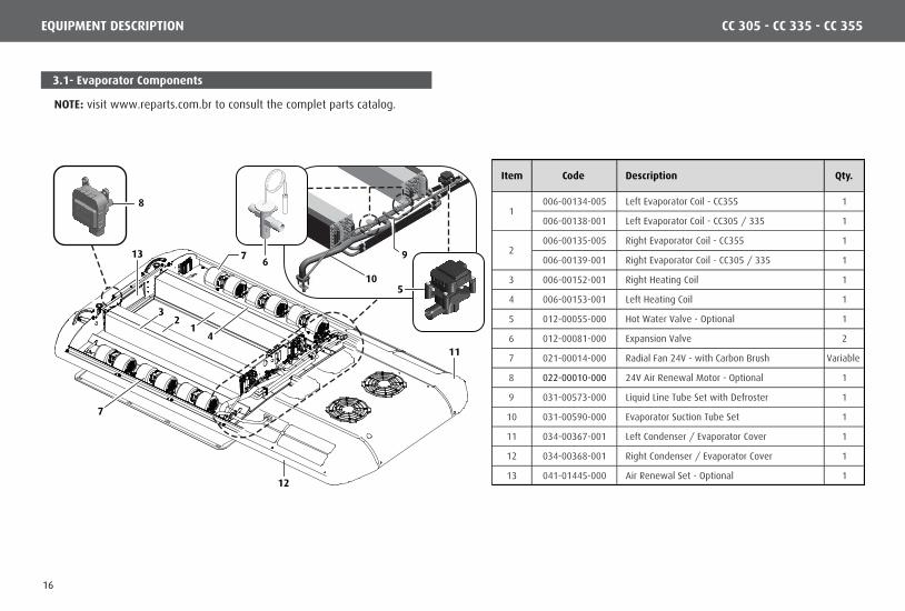
3.1- Evaporator Components
7
7
4
3
6
11
12
13
8
510
9
21
NOTE: visit www.reparts.com.br to consult the complet parts catalog.
Item Code Description Qty.
006-00134-005 Left Evaporator Coil - CC355 1
006-00138-001 Left Evaporator Coil - CC305 / 335 1
006-00135-005 Right Evaporator Coil - CC355 1
006-00139-001 Right Evaporator Coil - CC305 / 335 1
3 006-00152-001 Right Heating Coil 1
4 006-00153-001 Left Heating Coil 1
5 012-00055-000 Hot Water Valve - Optional 1
6 012-00081-000 Expansion Valve 2
7 021-00014-000 Radial Fan 24V - with Carbon Brush Variable
8 022-00010-000 24V Air Renewal Motor - Optional 1
9 031-00573-000 Liquid Line Tube Set with Defroster 1
10 031-00590-000 Evaporator Suction Tube Set 1
11 034-00367-001 Left Condenser / Evaporator Cover 1
12 034-00368-001 Right Condenser / Evaporator Cover 1
13 041-01445-000 Air Renewal Set - Optional 1
1
2
CC 305 - CC 335 - CC 355EQUIPMENT DESCRIPTION
16
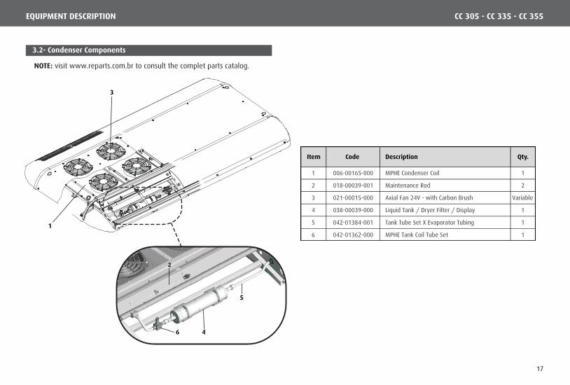
3.2- Condenser Components
1
3
Item Code Description Qty.
1 006-00165-000 MPHE Condenser Coil 1
2 018-00039-001 Maintenance Rod 2
3 021-00015-000 Axial Fan 24V - with Carbon Brush Variable
4 038-00039-000 Liquid Tank / Dryer Filter / Display 1
5 042-01384-001 Tank Tube Set X Evaporator Tubing 1
6 042-01362-000 MPHE Tank Coil Tube Set 1
CC 305 - CC 335 - CC 355EQUIPMENT DESCRIPTION
2
5
46
NOTE: visit www.reparts.com.br to consult the complet parts catalog.
17

3.3- Compressor Components - BOCK FKX 40/655K
1
2
3
84 7
6
10 9
1314
12
11
5
Item Code Description Qty.
1 014-00195-000 BOCK FKX40/655K Compressor 1
2 014-00197-000 Compressor Sealing Gaskets Set 1
3 014-00198-000 Compressor Valve Board Set 2
4 014-00199-000 Compressor Oil Pump 1
5 014-00200-000 Compressor Sealing Kit 1
6 014-00201-000 BOCK FKX40 Piston Assembly 4
7 014-00202-000 Compressor Roll Bearing 2
8 027-00002-000 Compressor Oil 2
9 041-00226-000 Compressor Clutch Assembly 1
10 041-00457-000 Clutch Kit without Pulley 1
11 029-00052-000 Magneto 1
12 029-00008-000 Ball Roller Bearing 1
13 014-00097-000 Pulley 2A/2B 1
14 017-00104-000 Bolt M12 x 40 1
CC 305 - CC 335 - CC 355EQUIPMENT DESCRIPTION
NOTE: visit www.reparts.com.br to consult the complet parts catalog.
18
EQUIPMENT DESCRIPTION
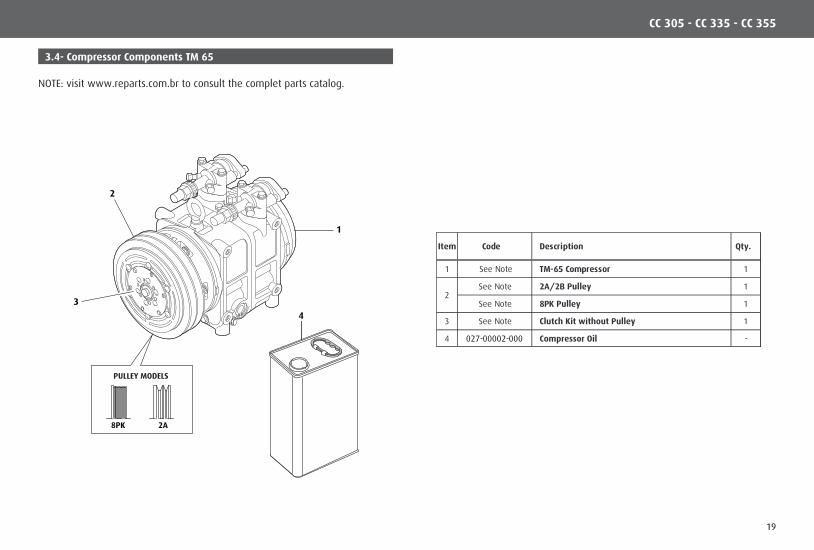
3.4- Compressor Components TM 65
1
3
2
PULLEY MODELS
8PK 2A
4
Item Code Description Qty.
1 See Note TM-65 Compressor 1
See Note 2A/2B Pulley 1
See Note 8PK Pulley 1
3 See Note Clutch Kit without Pulley 1
4 027-00002-000 Compressor Oil -
2
NOTE: visit www.reparts.com.br to consult the complet parts catalog.
CC 305 - CC 335 - CC 355
19

EQUIPMENT DESCRIPTION
3.5- Electric Components
63 9854 7
1110
CC 305 - CC 335 - CC 355
1 2
Item Code Description Qty.
1 See Note (*) SBU-400 Refrigeration Air Conditioning Controller 1
SBU-410 Air Conditioning Controller with Heating 1
SBU-410 Air Conditioning Controller with Renewal 1
3 004-00135-000 24V Water Pump 1
4 010-00018-000 High Pressure Switch 1
5 010-00019-000 Low Pressure Switch 1
6 See Note (*) EPCOS 3K Temperature Sensor 1
7 010-00016-000 Anti-Freeze Thermostat (Temperature Switch) 1
8 008-00025-000 125A Fuse 1
9 015-00031-000 Fuse Holder 1
10 See Note (*) Electric Control Board 24V 1
11 See Note (*) Relay 1
2 See Note (*)
NOTE: visit www.reparts.com.br to consult the complet parts catalog.
20
ELECTRICAL SYSTEM CC 305 - CC 335 - CC 355
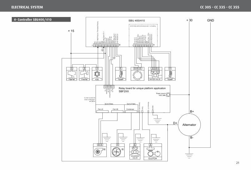
4- Controller SBU400/410 SBU 400/410
CLUTCHSOLENOID
VALVE
D+
TEMPTEMPPAPM ICEPBPM
Alternator
B+
B-
WATER VALVE
M
+ 30 GND
+ 15
Relay board for unique platform applicationSBF2XX
Fan LS Fan HS Condenser
Up to 6 fans Up to 4 fans
Power sourceVDC (M8)
Low
/ Hi
gh P
ress
ure
/ The
rmos
tat f
reez
ing
N.C.
N.C.
N.C.
N.C.
GND
GND
Duct
Tem
pera
ture
Duct
Tem
pera
ture
Fres
h Ai
r AFr
esh
Air B
GND
Wat
er V
alve
Wat
er V
alve
A
Wat
er V
alve
+5V
cc
Wat
er V
alve
BW
ater
Valv
e Po
t.Flo
or C
onve
ctor
W
ater
Pum
p (-
)
VCC
(+15
)
Conv
ecto
r
Alte
rnat
or S
ignal
(D+
)
Cond
ense
r
Radia
l S2
Fan
Radia
l S1
Fan
Clut
ch
Inne
r Tem
pera
ture
Inne
r Tem
pera
ture
Fan LS
Solenoid valve
Clutch
Alternator D+
GND RB
Fan HSCondenser
+15
+15
Condenser/Clutch
GND
(Rela
y Bo
ard)
In order to check the output configuration,
see SBF2xx
SC410 Only with Air Renewal and / or Heating
21

1- Personal Protection:
2- High Pressure: Other Care:
3- Hoses:
7- Toxic Gases:
6- Welding:
4- Hot Surface:
5- Rotation Components: 5- Safety Precaution
R134a
R134a
PSI
30
2010
0
10
20
30
4050
60
70
80
90
100
110
120
-40
-20
0
20
40
6080
100
120
140
160
180
200
R134a
PSI0
50
100
150200
250
300
-30
0
30
60
90
120150
180
210
240
270
300
330
350
CC 305 - CC 335 - CC 355
Air conditioning systems offers chemic, mechanic and electric risks.It is mandatory to wear IPE (Individual Protection Equipment), picture 1 to protect yourself from refrigerant gas, refrigerant oil, battery acid, waste launched, engine high temperature and noise.
The refrigerant in liquid state and high pressure causes a potential risk. When the refrigerant is sprayed to natural air, it can cause serious injuries to eyes and skin.
Check if manometer hoses are in good conditions, when holding them; stay far from belts, pulleys and hot surfaces.
The compressor discharges, exhaust pipes and other engine components can be extremely hot.
The fans, pulleys and belts are not visible under certain conditions. Special care must be taken when putting your hands near them.
Welding must be done carefully; it causes burns and spray toxic gases out. Provide ventilated places to do it.
The refrigerant gas along with flame becomes into toxic gases and can cause very serious breathing illness. Take special care in closed places, if gases scape somehow (leakage) and then it can cause no toxygen in the air.
• When handling and going up and down stairs, ladders and platforms, you can slide or they can break.
• Wear a seat belt always when working over 1.5m high.
• Never apply heat in recipients or pressured lines.
• Never operate the equipment if discharge service valve is closed.
• The refrigeration oil can cause irritation to your skin and eyes.
• Check if every screw are long enough and right tight.
• Components that are not in good conditions must be replaced by new ones due to safety reasons.
SAFETY PRECAUTION
22
SUSTAINABILITY
6- Product Discard
Concerned about sustainability at Valeo Climatização do Brasil - Veículos Comerciais S/A guides its customers and its authorized service network to discard products in an environmentally sound and safe manner.
Proper disposal of the product or components at the end of their useful life will contribute with the preservation and pollutinon reduction of the environment, creating economic growth through the Reverse Logistics Program.
According to Law 12,305 / 2010, the environmentally adequate destination of components (parts, oil, refrigerant) is required.
It is the responsibility of all to ensure that products and components are sent to appropriate treatment to companies approved by the environmental agencies.
For more information about our Reverse Logistics Program, please see our website: http://www.valeo-thermalbus.com/br
CC 305 - CC 335 - CC 355
23

Valeo Climatização do Brasil - Veículos Comerciais S/AAv. Rio Branco, 4688 - Bairro São Cristóvão - CEP 95060-145 | Caxias do Sul - RS - Brasil | Tel. +55 (54) 2101.5700www.valeo-thermalbus.com/br
24