cc-8118-120, cc-8118-240, cc-8118-153, cc-8218-120, cc ......at-8155 remote setpoint adjustor, dual...
TRANSCRIPT

Printed in U.S.A. 9/08 © Copyright 2008 TAC All Rights Reserved. F-17219-2
These self-contained units will provide staged linear (“first on”, “last off”) sequencing or staged progressive (“first on”, “last off”) sequencing.
The progressive model equalizes the wear on connected loads by staging (“first on, “last off”) and by automatic load jogging. The internal load jogger circuit alternates the use of the loads required to maintain the media control point of the sequencer by staging “on” an inactive load and staging “off” an active load every 8 minutes (approx.) in progressive sequence.
All models will provide sequence control of staged electric heat.
The TAC linear and progressive sequencers employ a unique method to obtain 100% proportional control of electric heat. The sequencers produce a proportional voltage output between stages to drive an electronic electric heat controller, controlling an additional load. This provides 100% proportional control between all stages, offering precise control over all
Table-1 Performance Table.
Part Number
Power Requirements
StagingStages Available
By Multi-Unit Operation
Throttling Rangea °C (°F)
Time Between Stages 10 Seconds Standard, 5 to 60 Seconds Resistor
Selectable
Factory Set Adjustable
Volts AC 11 VA 50/60 Hz °C (°F) °C (°F)
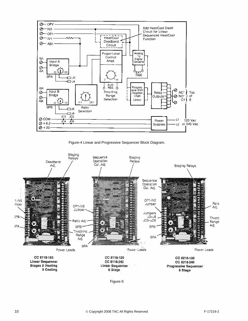
CC-8118-120 120 bLinear 8 Stage heat or cool48 Parallel
24 Sequence
1.6 3 1.1-5.5 2-10
CC-8118-240 240
CC-8218-120 120 bProgressive 8 Stage heat or cool48 Parallel
24 SequenceCC-8218-240 240
CC-8118-153 120cLinear 5 stage heat & 3 cool (adjustable
deadband between heat & cool)d30 Heat 18 Cool
In Parallel onlya The throttling range can be increased from 10°F to 40°F resistor selectable.b Factory set, direct acting bridges for heating, adjustable to provide reverse action for cooling.c Factory set, D.A. Bridges, Adjustable to provide R.A. for 5 cool, 3 heat. The 3 heat stages will not provide 100% proportional heat.d Deadband adjustable 0 to 8°C (0-15°F). Factory Set .5°C (1°F).
Relay Contact Electrical Rating Maximum Size for Typical Conductors
Volts AC
50/60 HzContact V.A.
RatingInrush
V.A.
Allen Bradley 50/60 Hz
Square D 50 Hz
Square D 60 Hz
120/240N.O. 125 1250 #4 #2 #3
N.C. 67 670 #3 #2 #2
24N.O. 25 250 #1 #0 #0
N.C. 13 130 #0 #00 #00
CC-8118-120, CC-8118-240,CC-8118-153, CC-8218-120,
CC-8218-240Electronic Controller
Eight Stage SequencerGeneral Instructions
Electronic Linear or Progressive Sequencer for Sequencing External Low or Line Voltage Contactors or Other Loads. All models have outputs to provide 100% proportional control of electric resistance heating.
2 © Copyright 2008 TAC All Rights Reserved F-17219-2
media. All sequencers except CC-8119-153 will provide 100% proportional control of 9 loads. (Example: 8 staged loads plus one load proportioned by an electronic electric heat controller.) CC-8118-153 will provide 100% proportional control of 6 loads. The number of loads possible with multi-unit operation from a single sensor with 100% proportional control is shown in the table below. Each sequencer requires an electronic electric heat controller, a CP-8425 or CP-80000 series unit.
Additional stages on linear sequencers in single unit operation can be obtained by using CC-8101 and CC-8102 electronic relays.
Control Inputs all Models1. Any TS-8000 sensor (1000 ohm Balco): The sequencer
has a dual marked -6 to 49°C (20 to 120°F) setpoint adjuster.
2. Two TS-8000 sensors (1000 ohm Balco):
a. Room and discharge uses a TS-8000 space sensor and a TS-8000 duct sensor.
b. Outdoor reset uses a TS-8000 duct or immersion sensor and a TS-8501 outdoor sensor.
The sequencers have a dual marked -6 to 49°C (20 to 120°F) setpoint adjuster for the second sensor (Example: discharge or outdoor air plus a .5 to 1 through 25 to 1 ratio adjustor.)
3. Remote setpoint adjuster (AT-8100 Series).
4. Power demand (2 to 10 Vdc) from a Power Monitor.
5. 1-15 Vdc, unit operates @ 2-5, 6-9, 10-13 Vdc.
6. 135 ohm slidewire transducer.
Control Outputs All Models1. Proportional 2-15 Vdc paralleling or sequencing five
additional TAC System 8000 devices.
2. Proportional 6-9 Vdc between each relay output of heating stages for proportional control of electric heat when used in conjunction with a CP-8425 or CP-80000 controller.
3. 20 Vdc, 35 ma power supply for use with other TAC System 8000 controls.
4. 6.2 Vdc, 4 ma power supply for use with remote setpoint adjusters (AT-8100 series) and TS-8601 discharge sensor, etc.
The units have a 10 second time delay between stages and return to cold start on power interruption.
The electronic circuitry and 8 SPDT staging relays are contained in a sturdy metal housing. Four 1/2 to 3/4 inch concentric knockouts are provided, two on each end.
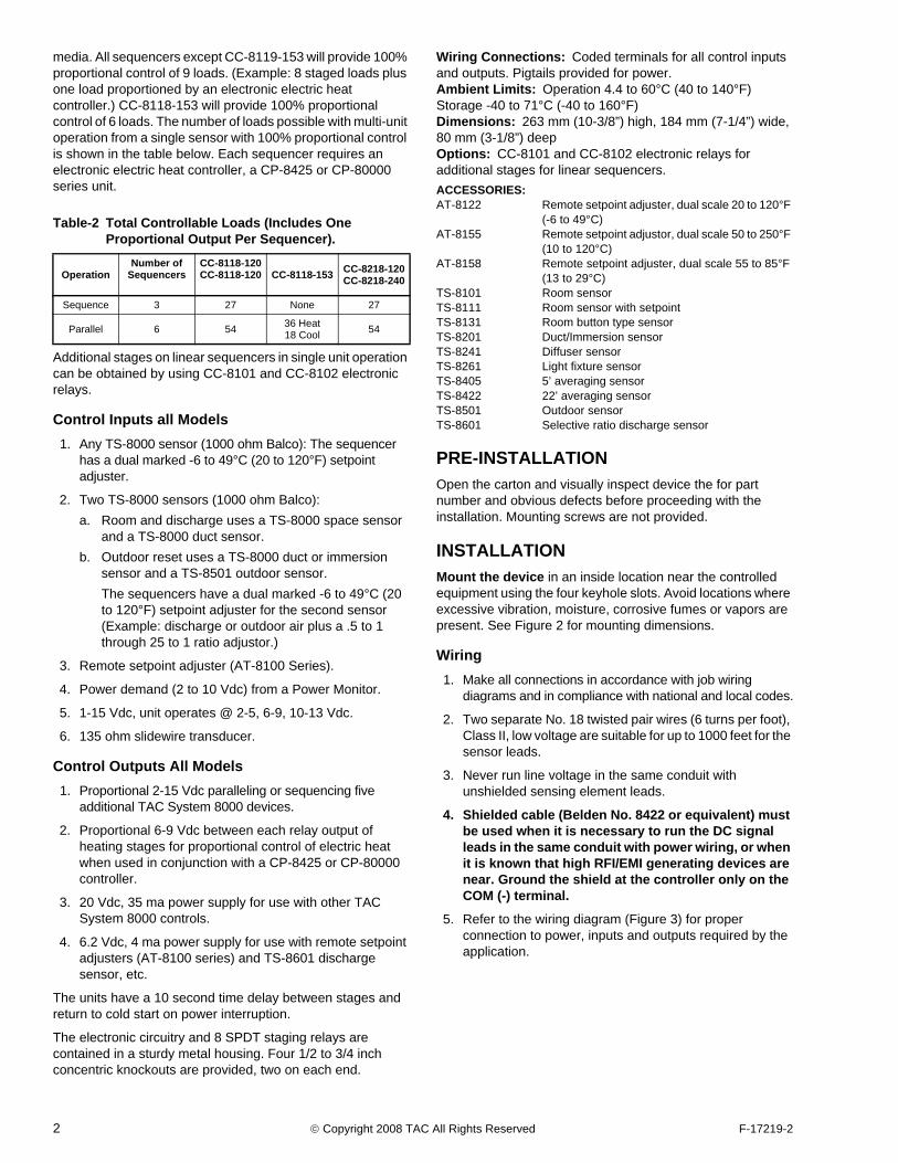
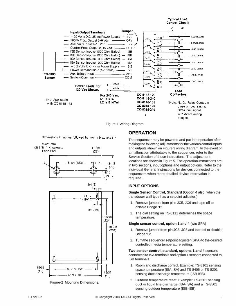
Wiring Connections: Coded terminals for all control inputs and outputs. Pigtails provided for power.Ambient Limits: Operation 4.4 to 60°C (40 to 140°F) Storage -40 to 71°C (-40 to 160°F)Dimensions: 263 mm (10-3/8”) high, 184 mm (7-1/4”) wide, 80 mm (3-1/8”) deepOptions: CC-8101 and CC-8102 electronic relays for additional stages for linear sequencers.ACCESSORIES:AT-8122 Remote setpoint adjuster, dual scale 20 to 120°F
(-6 to 49°C)AT-8155 Remote setpoint adjustor, dual scale 50 to 250°F
(10 to 120°C)AT-8158 Remote setpoint adjuster, dual scale 55 to 85°F
(13 to 29°C)TS-8101 Room sensorTS-8111 Room sensor with setpointTS-8131 Room button type sensorTS-8201 Duct/Immersion sensorTS-8241 Diffuser sensorTS-8261 Light fixture sensorTS-8405 5’ averaging sensorTS-8422 22’ averaging sensorTS-8501 Outdoor sensorTS-8601 Selective ratio discharge sensor
PRE-INSTALLATIONOpen the carton and visually inspect device the for part number and obvious defects before proceeding with the installation. Mounting screws are not provided.
INSTALLATIONMount the device in an inside location near the controlled equipment using the four keyhole slots. Avoid locations where excessive vibration, moisture, corrosive fumes or vapors are present. See Figure 2 for mounting dimensions.
Wiring1. Make all connections in accordance with job wiring
diagrams and in compliance with national and local codes.
2. Two separate No. 18 twisted pair wires (6 turns per foot), Class II, low voltage are suitable for up to 1000 feet for the sensor leads.
3. Never run line voltage in the same conduit with unshielded sensing element leads.
4. Shielded cable (Belden No. 8422 or equivalent) must be used when it is necessary to run the DC signal leads in the same conduit with power wiring, or when it is known that high RFI/EMI generating devices are near. Ground the shield at the controller only on the COM (-) terminal.
5. Refer to the wiring diagram (Figure 3) for proper connection to power, inputs and outputs required by the application.
Table-2 Total Controllable Loads (Includes One Proportional Output Per Sequencer).
OperationNumber of
SequencersCC-8118-120 CC-8118-120 CC-8118-153 CC-8218-120
CC-8218-240
Sequence 3 27 None 27
Parallel 6 54 36 Heat18 Cool 54
F-17219-2 © Copyright 2008 TAC All Rights Reserved 3
Figure-1 Wiring Diagram.
Figure-2 Mounting Dimensions.
OPERATIONThe sequencer may be powered and put into operation after making the following adjustments for the various control inputs and outputs shown on Figure 3 wiring diagram. In the event of a malfunction attributable to the sequencer, refer to the Service Section of these instructions. The adjustment locations are shown in Figure 5. The operation instructions are in two sections, input options and output options. Refer to the individual General Instructions for devices connected to the sequencers when more detailed device information is required.
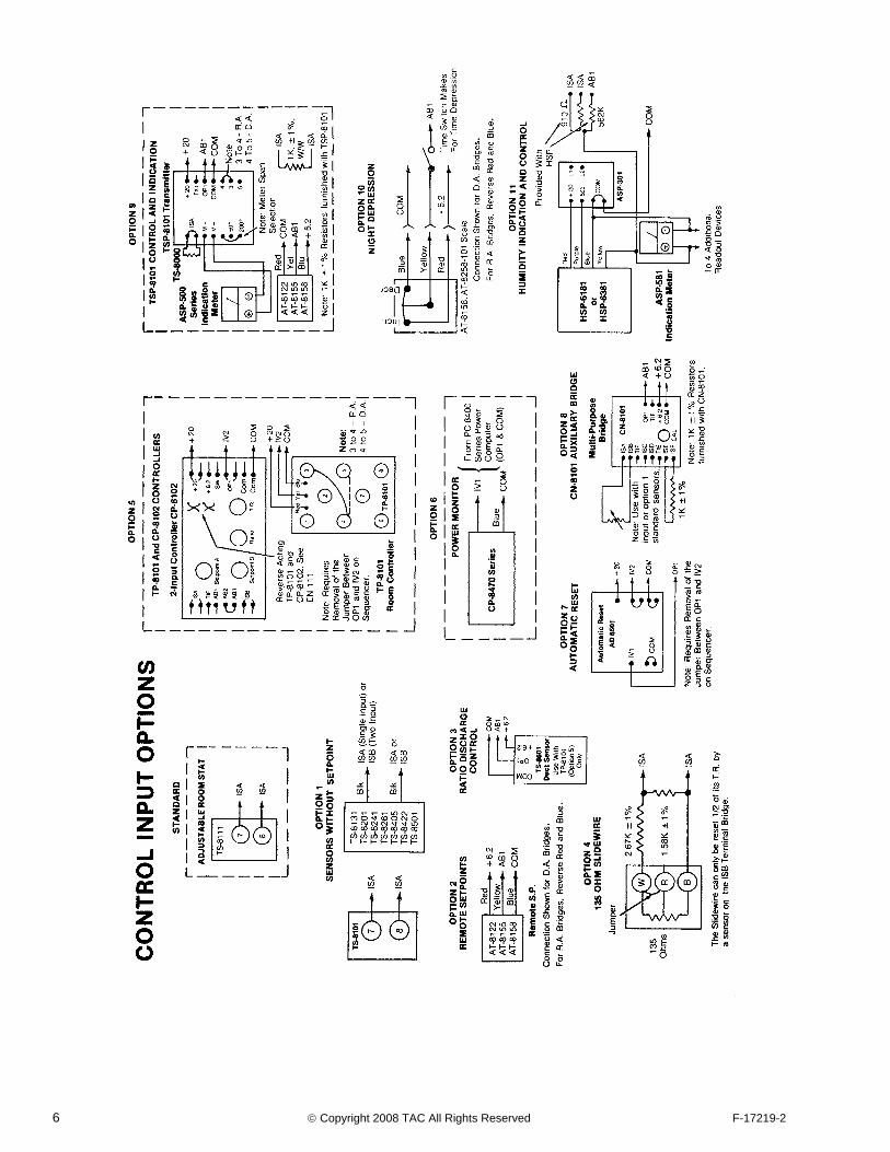
INPUT OPTIONSSingle Sensor Control, Standard (Option 4 also, when the transducer wall type has a setpoint adjuster.)
1. Remove jumpers from pins JC5, JC6 and tape off to disable Bridge “B”.
2. The dial setting on TS-8111 determines the space temperature.
Single sensor control, option 1 and 4 (w/o SPA)
1. Remove jumper from pin JC5, JC6 and tape off to disable Bridge “B”.
2. Turn the sequencer setpoint adjuster (SPA) to the desired controlled media temperature setting.
Two sensor control, standard, options 1 and 4 sensors connected to ISA terminals and option 1 sensors connected to ISB terminals.
1. Room and discharge control. Example: TS-8101 sensing space temperature (ISA-ISA) and TS-8405 or TS-8201 sensing duct discharge temperature (ISB-ISB).
2. Outdoor temperature reset. Example: TS-8201 sensing duct or liquid line discharge (ISA-ISA) and a TS-8501 sensing outdoor temperature (ISB-ISB).

4 © Copyright 2008 TAC All Rights Reserved F-17219-2
3. The jumpers J3 thru J6 are factory set for these applications, i.e., “C” on the internal bridge diagram on the Figure 3 wiring diagram. For other input/output requirements, refer to these instructions.
Remote setpoint adjusters (option 2) used with options 1 and 4 sensors without setpoint adjusters. Setpoint A (SPA) must be at 70°F. Set remote setpoint at the desired media temperature.
Night depression (option 10) used with standard and options 1, 2, 4, 8 and 9. Connect to separate timer switch for programmed night depression.
Multi-Purpose bridge CN-8101 (option 8) Three sensor application: Use the authority adjustment dial on CN-8101 (.5-20 to 1) to set the authority of the third element in respect to the sequencer main element.
Temperature control and indication using TSP-8101 transmitter (option 9)
1. The TS-8000 sensor cannot have a setpoint dial.
2. For application requiring reverse action (Example: jumper 3 to 4 on TSP-8101), it is necessary to reverse the SPA action of the sequencer “A” bridge. The SPA is reversed by placing a jumper J3 on Pin JC4 and jumper J4 on Pin JC3. Jumpers J5 and J6 must be removed from Pins JC5 and JC6 and be taped off to disable bridge “B”.
Automatic reset using AD-8501 (option 7).
Humidity control and indication (option 11) Reverse-action of bridge “A”. Place jumper J3 on Pin JC4 and jumper J4 on Pin JC3. Jumpers J5 and J6 must be removed from pins JC5 and JC6 and taped off to disable bridge “B”.
A power monitor (option 6) can be connected to the sequencer. A 2-10 Vdc signal from OP1 and COM of the PC-8400 series power computer inside the CP-8470 series power monitor will operate all sequencer models except CC-8118-153.
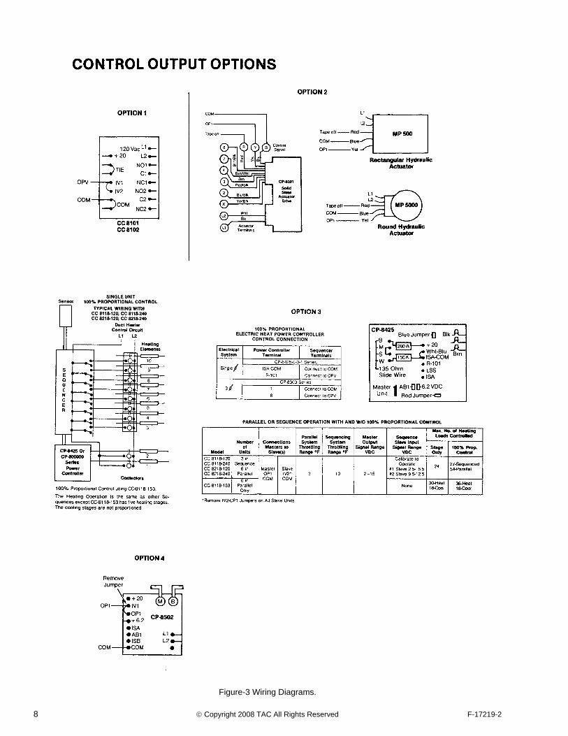
OUTPUT OPTIONSTo add stages to the linear sequencers only using CC-8101 (one stage) or CC-8102 (two stage) (option 1).
Note: The added stage will not have the time delay feature.
For nine stages, set the differential jumper on the CC-8101 to .5 pin, rotate the SPA (CW) on the sequencer until the OPV to COM voltage reads 9 Vdc. Adjust the drop out potentiometer until the relay on CC-8101 drops out.
For ten stages, set the differential jumper on the CC-8102 to .5 volts on both stages. Rotate the SPA (CW) on the sequencer until the OPV to COM voltage reads 9 Vdc. Adjust
stage 1 drop out potentiometer until stage 1 drops out. Rotate SPA (CW) again until OPV to COM voltage reads 9.5 volts. Adjust stage 2 drop out potentiometer until stage 2 drops out.
To control valves or dampers using actuators with CP-8301 stolid state drive or MP-5000 series actuators, wire per option 2.
To provide staged sequence or parallel multi-unit operation of all standard models, refer to output option 3 table. (Exception: CC-8118-153 will operate in parallel only)
Calibration procedure for a master and one slave in sequence operation:
1. Master unit
Remove sensors and replace with 1000 ohm ± .1% w.w. resistors (SYZE-12987 test kit) on terminals ISA-ISA and ISB-ISB.
Read 7.5 Vdc between OP1 (+) and COM (-) terminals. Turn SPA if required.
Turn “CAL” potentiometer full c.w. (viewed from the col-ored plastic side). All relays must energize before pro-ceeding.
Turn “CAL” potentiometer c.c.w. until voltage between OPV (+) and COM (-) reads 9 Vdc.
2. Slave Unit
Turn “CAL” potentiometer full c.c.w. (viewed from the colored plastic side). All relays must be de-energized before proceeding.
Turn “CAL” potentiometer c.w. until 6 Vdc is read between OPV (+) and COM (-).
3. Remove meter, 1000 ohm resisters and reconnect the sensors to ISA-ISA and ISB-ISB terminals.
4. Turn the master unit SPA to the desired setpoint, and put the units in operation.
Calibration procedure for a master and two slaves in sequence operation:
1. Master Unit
Remove sensors and replace with 1000 ohm ± .1% resistors (SYZE-12987 test kit) on terminals ISA-ISA and ISB-ISB.
Turn SPA C.W. until 5.5 Vdc is read between OP1 (+) and COM (-) terminals.
2. #1 Slave (low voltage signal operation)
Adjust “CAL” potentiometer full C.C.W. All relays must de-energize before proceeding.
Turn “CAL” potentiometer C.C.W. until 6 Vdc is read between OPV (+) and COM (-) terminals.
3. Master Unit. Turn SPA C.C.W. until 9.5 Vdc is read between OP1 (+) and COM (-) terminals.
4. #2 Slave (high voltage signal operation)
Turn the “CAL” potentiometer C.C.W. until 9 Vdc is read between the OPV (+) and COM (-) terminals.
5. Remove meter, 1000 ohm resistors and reconnect the sensors to ISA-ISA and ISB-ISB terminals.
6. Turn the SPA of the master to the desired setpoint and put the units in operation.
Table-3 Sequencer Settings.
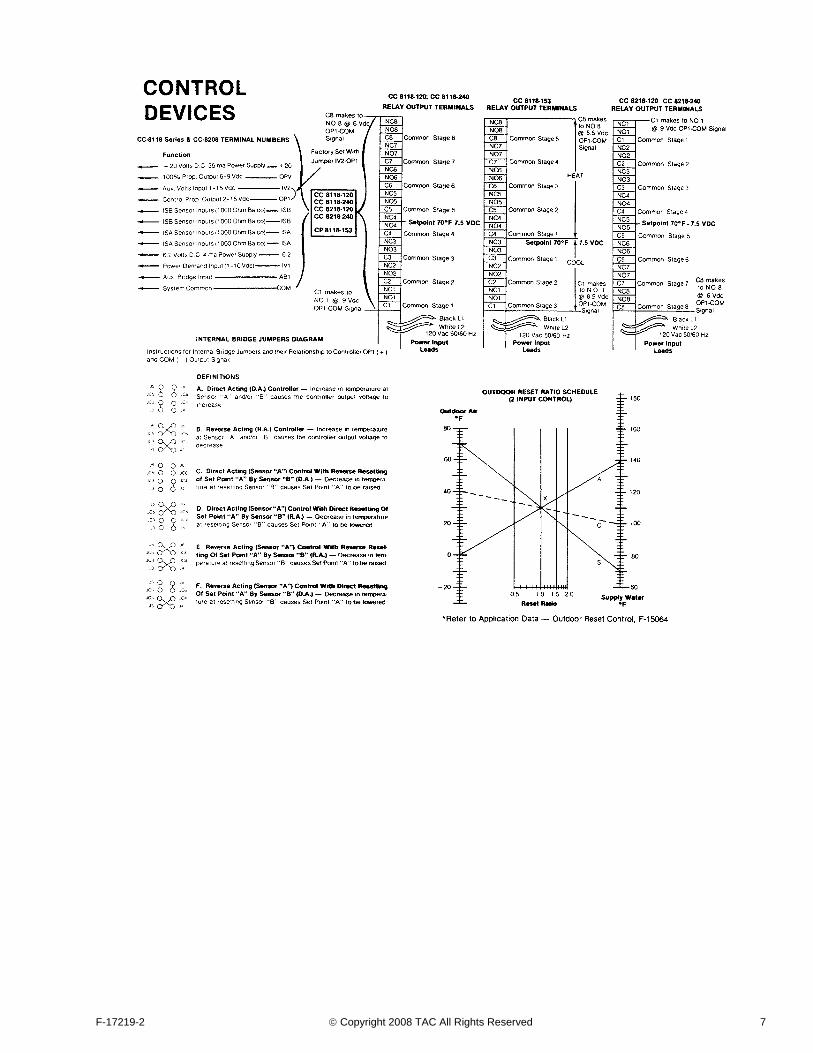
Room ISA+ISA Outdoor Reset (see Outdoor Reset Ratio Schedule on the
Wiring Diagram, Figure 3)Discharge ISB+ISB
Throttling Range
Factory Set 3°FAs required for stable control normally in the range of 6 thru
10°F
Ratio Adjustment
Factory Set 1:1As required, normally in the range of .5 to 1 thru 25 to 1

F-17219-2 © Copyright 2008 TAC All Rights Reserved 5
Calibration procedure for all models with a master and on or two slaves in parallel operation.
Normally, no calibration is required since the master and slave(s) operate in unison when wired per the diagram.
To provide 100% proportional control for single and multi-unit operation up to 27 electric resistance load, refer to output option 3. The load proportioned by the electronic electric heat controller must be twice the size of the staged loads.
Interface with a pneumatic system using CP-8502 electronic-pneumatic transducer connect as shown in option 4.
SERVICE
Factory Setting Verification70°F setpoint adjuster “A” (SPA) for the “A” bridge which responds to a TS-8000 series on the ISA terminals. Jumper J3 is on pin JC3, jumper J4 is on pin JC4.
Note: This is direct acting. (Example: A temperature increase results in an OP1-COM voltage increases with bridge “B” disabled by pulling the jumpers J5 and J6 from pins JC5 and JC6.)
70°F setpoint adjuster “B” (SPB) for the “B” bridge which responds to a TS-8000 series sensor on the ISB terminals. Jumper J5 is on pin JC5, jumper J6 is on pin JC6. A temperature increase results in an OP1-COM voltage increase with bridge “A” disabled by pulling the jumpers J3 and J4 from pins JC3 and JC4.
Throttling range adjuster (T.R.) at 3°F A temperature increase of 1.5°F detected at the ISA or ISB sensor will result in an OP1-COM voltage change of +1.5 volts. A temperature decrease of 1.5°F detected at the ISA or ISB terminals will result in an OP1-COM voltage change of - 1.5 Vdc. Disable bridge “B” when the change is detected at the ISA sensor. Disable bridge “A” when the change is detected at the ISB sensor.
To increase the throttling range above 10°F, rotate the throttling range adjustor to the full CW end and solder a resistor from the throttling range table below across the “Aux. Res” pins.
Ratio adjuster (RATIO) is factory set at 1:1, a 70°F decrease at sensor “B” (ISB terminals) will increase the control point of bridge “A” 70°F. When set at 20:1 ratio, a 70°F decrease at
sensor B will increase the control point of bridge “A” 3.5°F. When set at .8:1, a 70°F decrease at sensor “B” will increase the control point of bridge “A” 87°F.
Voltage output signals
1. OP1-COM 2-15 Vdc factory calibrated @ 7.5 Vdc with 1000 ohm ± .1% w.w. resistors (SYZE-12987 test kit) are connected to the ISA and ISB terminals.
2. Use OP1-COM signal for controlling other TAC System 8000 Controlled devices.
3. OPV-COM 6-9 Vdc factory calibrated @ 7.5 Vdc when OP1-COM signal is 7.5 Vdc. The OPV-COM signal voltage increases from 6 to 9 Vdc as OP1-COM descreases .375 Vdc. DPV-COM signal automatically changes to 7.5 Vdc as each stage pulls in or drops out.
Power supplies
1. +20 Vdc + 1-1.5 Vdc 35 ma between +20 and COM (-) terminals
2. +6.2 ±.4 Vdc 4 ma between +6.2 and COM (-) terminal
Time between stages
10 sec. with standard value of 1.5 Meg. ohm resistor on “Ext. time” pins. The time between staging for both the linear and the progressive models may be changed by using a resistor selected from the table below that corresponds to the desired interstage time. The jogger circuit timing for the progressive model varies with interstage timing as shown.
The jogger circuit can be disabled by tying the ends of jumper J7 together.
Staging
Eight stages pull “in” thru a 9-6 Vdc OP1-COM signal. Stage differential .375 Vdc approx. on dropout.
CC-8118-120 CC-8118-240 Relays “on” 1, 2, 3, 4, 5, 6, 7, 8
Relays “off” 8, 7, 6, 5, 4, 3, 2, 1
CC-8218-120 CC-8218-240 Relays “on” 1, 2, 3, 4, 5, 6, 7, 8
Relays “off” 1, 2, 3, 4, 5, 6, 7, 8
CC-8118-153 Heat Relays “on” 4, 5, 6, 7, 8
Relays “off” 8, 7, 6, 5, 4
Cool Relays “on” 3, 2, 1
Relays “off” 1, 2, 3
CC-8118-153 only
The temperature deadband adjuster between stage 1 heat and stage 1 cool is factory set at 1.33 to produce a 1°F deadband.
Throttling Range Resistor Value 1/4 Watt Min., 5% Tol.
12 2.2 Meg
14 1.2 Meg
16 750K
18 560K
20 430K
24 300K
32 200K
40 150K
Interstage Time (Sec) Ext. Time Resistor Jog Time (Min)
5 680k 4
10 Std. 7
15 2.2 Meg 10
20 2.7 Meg 12
30 3.3 Meg 18
40 4.7 Meg 25
50 5.6 Meg 30
60 6.8 Meg 35
6 © Copyright 2008 TAC All Rights Reserved F-17219-2
F-17219-2 © Copyright 2008 TAC All Rights Reserved 7
8 © Copyright 2008 TAC All Rights Reserved F-17219-2
Figure-3 Wiring Diagrams.
F-17219-2 © Copyright 2008 TAC All Rights Reserved 9
Determine and Establish Input IntegrityProvide 120 or 240 Vac. 120 Vac must be available at the black and white input leads. 240 Vac must be available at the black and black/yellow input leads.
TS-8000 Sensors. Remove the leads from ISA and/or ISB terminals and read 1000 ohms ±100 ohms across the leads when the sensor temperature is about 70°F (the sensor changes 2.2 ohms per °F). Replace defective sensors or correct open or shorted wiring.
Verify that input signal voltages from other controllers are present and correct. Provide the correct input voltage.
Determine and Establish Output Integrity Sequencer power supplies1. Check the 20 Vdc +1-1.5 Vdc in the controller. Connect a
VOM between +20 and terminal COM (-). If the 20 Vdc is not present or is widely out of tolerance, consider the controller as defective and replace.
2. Check the +6.2 ±.4 Vdc source in the controller. Connect a VOM between terminal +6.2 and terminal COM (-). If the +6.2 Vdc is not present or is out of tolerance, consider the controller as defective and replace.
Relay action. Place 1000 ohm ±.1% w.w. resisters (SYXE-12987 test kit) on terminals ISA-ISA and ISB-ISB. Turn SPA to 120°F. All N.O. relay terminals must be closed after staging delays. Turn SPA to 20°F. All N.O. relay contacts must be open after staging delays. Replace the unit if the relays do not preform as described.
Verify continuity of wiring to controlled devices. Correct open or incorrect wiring.
Verify the controlled device action. (Example: Heating or cooling equipment.) Notify the device supplier for corrective action.
Verify output control voltage signals
1. OP1-COM with resistors placed as in relay action above, turn SPA to 120°F. Read OP1 (+) COM (-) signal 2 ±1 Vdc using a 20000 ohm/volt VOM. Turn SPA to 20°F read 15 ±1 Vdc. Replace the unit if the voltages are not present.
2. OPV (+) COM (-) with resistors placed as in Relay Action, turn SPA to approximately 80°F, wait for all relays to stage on. (CC 8118-153 5 heat relays on.) Read OPV (+) COM (-) signal in excess of 9 Vdc. Turn SPA to approximately 60°F, wait for all relays to stage off. (CC 8118-153 3 cool relays on.) Read less than 6 Vdc using a 20000 ohm/volt VOM. This signal must change automatically to 1.5 ±.5 Vdc as each stage relay pulls in or drops out. Turn SPA very slightly to detect this action. (CC 8118-153, this action does not occur within the cooling stages.) Replace the unit if the voltages are not present.
Verify Controller SettingsVerify timing between stages. If other than 10 ±4 Sec., replace the 1.5 Meg. ohm resistor.
Verify J3, J4, J5, J6 jumper locations. Change to factory settings or place as required for the application.
Verify calibration. To recalibrate, place resistors as in relay action with SPA and SPB set at 70°F.
1. Disable bridge “B” by pulling the jumpers J5 and J6 from pins JC5 and JC6.
2. Rotate the SPA shaft until OP1 (+) COM (-) signal is 7.5 ±.5 Vdc.
3. Hold the SPA shaft firmly and rotate the pointer in a CCW direction until the pointer is on the 70°F mark of the dial scale.
4. Insert jumpers J5 and J6 on pins JC5 and JC6.
5. Rotate the SPB shaft until OP1 (+) COM (-) signal is 7.5 ±.5 Vdc.
6. Hold the SPB shaft firmly and rotate the pointer in a CCW direction until the pointer is on the 70°F mark of the dial scale.
CC-8118-153 Temperature Deadband AdjustmentTurn the deadband dial to a higher setting to increase the deadband from the standard 1°F setting. The deadband can be decreased by turning the dial to a lower setting.
The deadband setting table below shows various deadband settings and the resulting control span.
The control span is the temperature change required to stage on all stages. The control span equals the deadband dial setting times the throttling range.
The deadband equals the control span minus the throttling range.
THEORY OF OPERATION SECTIONReference Block Diagram Figure 4.
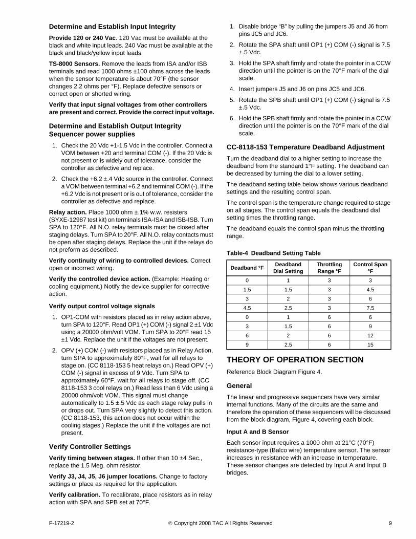
GeneralThe linear and progressive sequencers have very similar internal functions. Many of the circuits are the same and therefore the operation of these sequencers will be discussed from the block diagram, Figure 4, covering each block.
Input A and B Sensor
Each sensor input requires a 1000 ohm at 21°C (70°F) resistance-type (Balco wire) temperature sensor. The sensor increases in resistance with an increase in temperature. These sensor changes are detected by Input A and Input B bridges.
Table-4 Deadband Setting Table
Deadband °F Deadband Dial Setting
Throttling Range °F
Control Span °F
0 1 3 3
1.5 1.5 3 4.5
3 2 3 6
4.5 2.5 3 7.5
0 1 6 6
3 1.5 6 9
6 2 6 12
9 2.5 6 15
10 © Copyright 2008 TAC All Rights Reserved F-17219-2
Figure-4 Linear and Progressive Sequencer Block Diagram.
Figure-5
F-17219-2 © Copyright 2008 TAC All Rights Reserved 11
Input A and B Bridges
Each bridge input accepts the sensor resistance signal. A bridge converts the resistance signal change into a DC millivolt signal change. The output from input A bridge is fed to the proportional control and voltage amplifier. The output from Input B bridge is fed to the ratio selection network. Each bridge can be connected for either direct or reverse acting bridge output.
Ratio Selection Network
The ratio selection network allows selection of the desired input B bridge gain in order to accomplish resetting type control systems. The output of the ratio selection network is fed to the proportional voltage control amplifier.
Proportional Voltage Control Amplifier
The control amplifier sums and amplifies the millivolt output signal from input A and B bridges. The control amplifier output is a proportional 2 to 15 Vdc signal which is fed to the analog to digital converter amplifier. The amplifier uses overall negative feedback as a means of gain adjustment. This gain adjustment is the throttling range adjustment of the sequencers.
Analog to Digital Converter
These circuits receive the proportional output voltage from the proportional control amplifier. They provide sequencer calibration, a clock-timed pulse train signal and a digital high or low level signal voltage. The pulse train signal is generated above or below the 9 and 6 Vdc levels. The digital high and low level signals are generated when the output voltage is above or below the 7.5 Vdc level.
Shift Register Logic
This circuitry receives the high or low level and pulse signal from the analog to digital converter and stores them for control of the relays in the output section. These shift register sections are needed to operate in either linear or progressive sequence. In the linear model, CC-8118-153, a heat/cool deadband circuit is added in the IV2 line to the analog to digital converter. This circuit provides the deadband and heating/cooling functions. The shift register logic section is also rewired to provide the 3 cool, 5 heat output signals.
Relay Outputs
This section amplifies the signals received from the shift register section and operates the output relays. The relays are single pole double throw. The contact load capacities are located on the performance table.
Power Supplies
The sequencers have internal power supplies of +20 and +6.2 volts for use with their own circuits and also for external circuits. These supplies may be loaded up to 35 ma on the 20 volts and 4 ma on the 6.2 volt supply.
Heat/Cool Deadband Circuit (Linear Sequencer Only)
This section receives the proportional control signal (OP1 or IV2) and provides an adjustable reset current to the analog to digital converter. This section creates a deadband between the heating and cooling relay action.

Copyright 2008, TACAll brand names, trademarks and registered trademarks are the property of their respective owners. Information contained within this document is subject to change without notice.
F-17219-2
www.tac.com
TAC1354 Clifford AvenueP.O. Box 2940Loves Park, IL 61132-2940