ccr groundwater monitoring system...nebraska city, nebraska june 2016 2 1.0 introduction on april...
TRANSCRIPT

CCR Groundwater
Monitoring System
Omaha Public Power District
Nebraska City Station
NC1 Ash Disposal Area
Nebraska City, Nebraska
June 2016

This page intentionally left blank.

OPPD NC1 Ash Disposal Area CCR Groundwater Monitoring System
Nebraska City, Nebraska June 2016
i
OPPD Nebraska City Station
NC1 Ash Disposal Area
CCR Groundwater Monitoring System
Table of Contents
Professional Engineer Certification ..................................................................................... 1
1.0 Introduction ................................................................................................................ 2
2.0 Facility Background .................................................................................................... 2
3.0 Site Hydrogeology Summary ....................................................................................... 2
4.0 Groundwater Monitoring System ................................................................................ 4
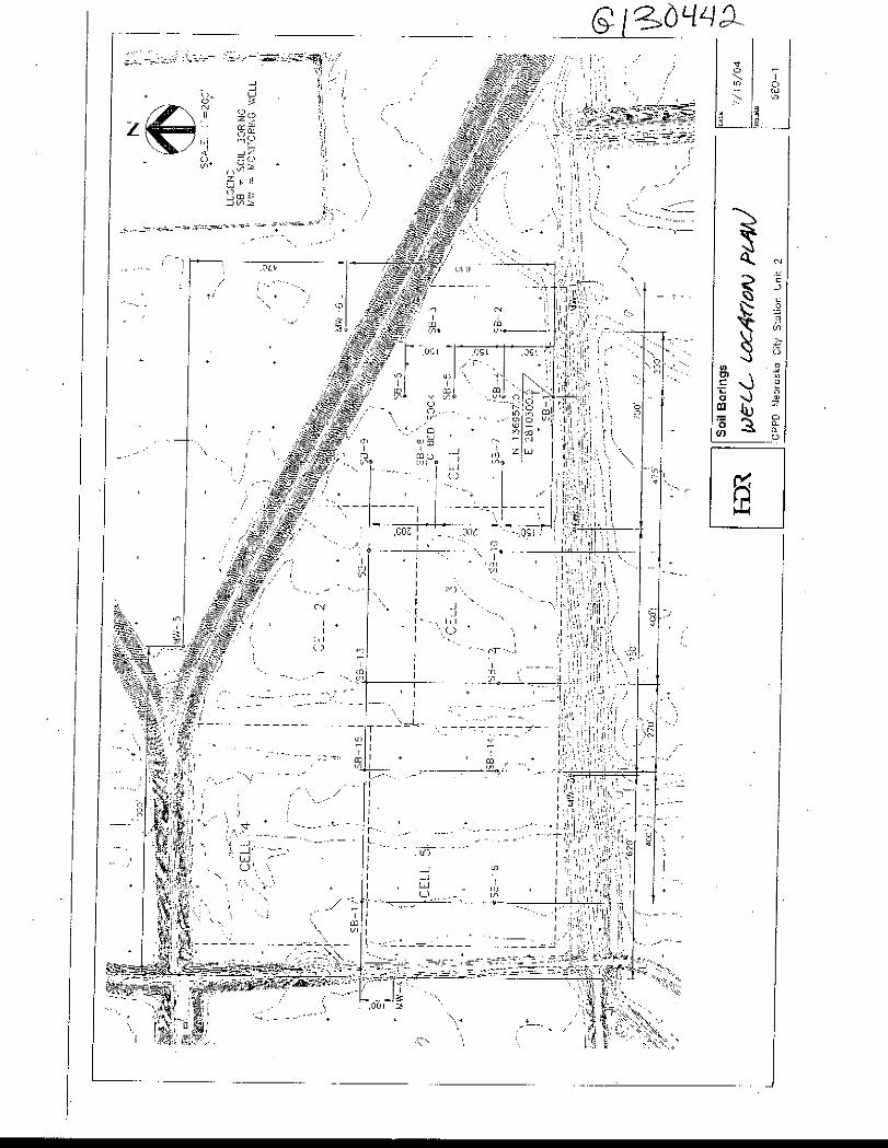
Figure 1 NC1 Ash Disposal Area, Groundwater Monitoring Well Locations ......................... 6
List of Tables
Table 1. NC1 Ash Disposal Area, Groundwater Monitoring Well System
Appendices
Appendix A Monitoring Well Documentation

This page intentionally left blank.


OPPD NC1 Ash Disposal Area CCR Groundwater Monitoring System
Nebraska City, Nebraska June 2016
2
1.0 Introduction On April 17, 2015 the U.S. Environmental Protection Agency (EPA) published the final rule for
the regulation and management of Coal Combustion Residuals (CCR) under the Resource
Conservation and Recovery Act (RCRA). The rule – effective on October 19, 2015 – applies to
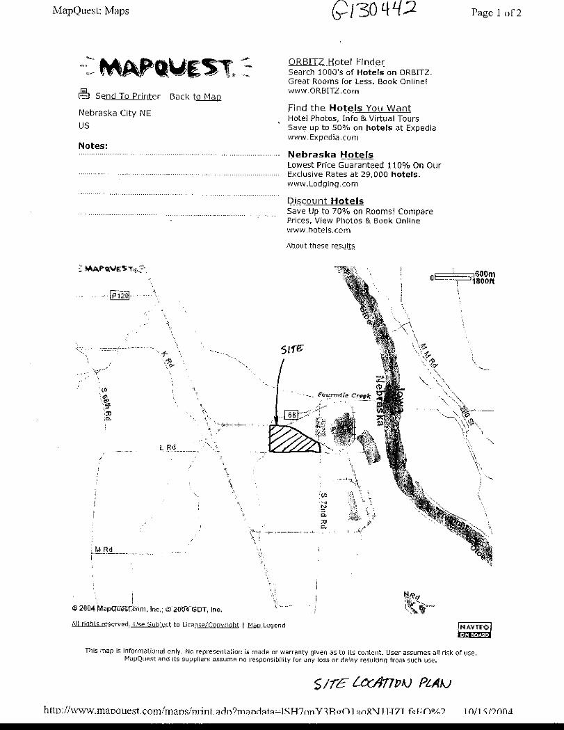
Omaha Public Power District’s (OPPD’s) Nebraska City Generating Station. The Station, located
southeast of Nebraska City, Nebraska has two coal-fired combustion units – Unit 1 and Unit 2.
CCR from both units may be disposed in the NC1 Ash Disposal Area.
The CCR Rule, 40 CFR Subpart D-Standards for the Disposal of CCRs, Section §257.91 requires a
groundwater monitoring system that consists of sufficient number of wells at appropriate
locations and depths based on site-specific technical information, to yield groundwater samples
from the uppermost aquifer that:
• Accurately represent the quality of both background groundwater, and groundwater
passing the boundary of the CCR unit
• Monitor potential contaminant pathways
The groundwater monitoring system at the NC1 Ash Disposal Area meets those requirements.
This report includes the following sections in support of the certification.
• Section 1.0 Introduction
• Section 2.0 Facility Background
• Section 3.0 Site Hydrogeology Summary
• Section 4.0 Groundwater Monitoring System
2.0 Facility Background OPPD has a two-unit (Unit 1 and Unit 2) fossil fuel-fired generating plant at the Nebraska City
Station (Station) southeast of Nebraska City, Nebraska. This Station has two existing CCR
landfills that are permitted under the current NDEQ Title 132 regulations for fossil fuel
combustion ash disposal (the NC1 Ash Disposal Area and NC2 Ash Disposal Area).
The NC1 Ash Disposal Area is an unlined CCR landfill of approximately 52 acres that has
historically received CCR for disposal and is permitted with the State of Nebraska. NC1 Ash
Disposal Area is an active, existing CCR landfill as defined by the CCR rule.
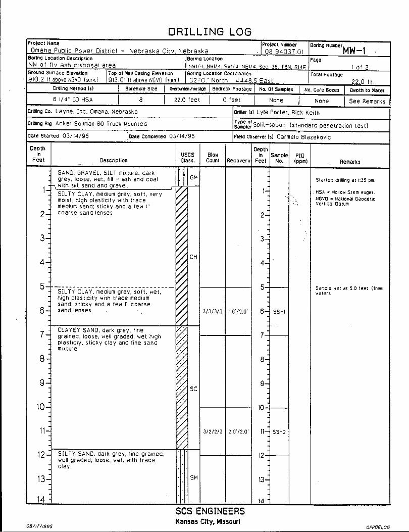
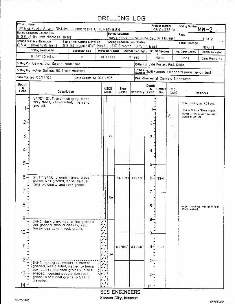
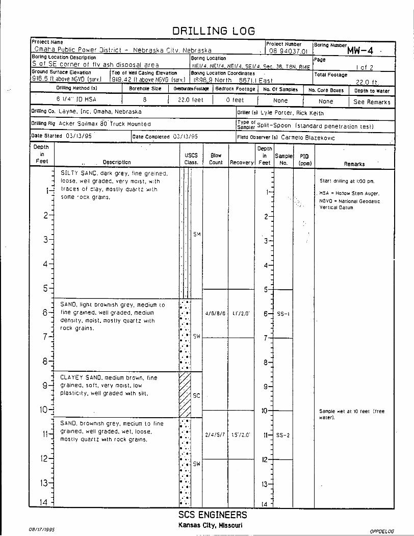
3.0 Site Hydrogeology Summary Based on soil boring advanced at the Station in 2006, the bedrock, in the form of shale, was
encountered at a depth of 89 feet below ground surface. The uppermost aquifer, Missouri River
Alluvium, depth is anticipated to be from 2 feet to 89 feet below ground surface (bgs).
According to the hydrology assessment conducted at the site in 1995 by SCS Engineers titled
Hydrologic Investigations Report. The broad upland areas of the Station are underlain by the
unconsolidated wind-blown and glacial deposits of Pleistocene age. The surface of the site is
generally overlain by fine-grained or cohesive deposits near the surface, based on a study
conducted by D’Appolonia Consulting Engineers in 1975. These deposits consist of silty clays,
clayey silts, silty sands and fine sands. The bedrock underlying the Station area is medium hard

OPPD NC1 Ash Disposal Area CCR Groundwater Monitoring System
Nebraska City, Nebraska June 2016
3
red to gray shale. Several areas outside the Station area are underlain by a thin formation of
limestone interbedded with shale.
Data from the boring logs for the monitoring wells and soil borings at the Station indicates that
the subsurface geology at the ash disposal area consists of the following:
• 3 feet of light brown to dark grayish brown lean clay (CL) (Fill/Topsoil), overlying,
• Approximately 9 feet of alluvium consisting of light brown to grayish brown silty clayey
sand (SM), poorly graded sand with silty sand (SP-SM), silt with very fine sand to silty
very fine sand (ML/SM), and high plastic clay (CH), overlying,
• 28 to 77 feet of gray poorly graded sand (SP) to the boring completion depths varying
from 40 to 89 feet.
• Some borings indicate that bedrock was encountered at a depth of 103.5 feet.
In the general vicinity of the Station, two primary sources of groundwater are present, Missouri
River alluvium and glacial deposits in the upland area west of the Station property.
Groundwater in the Missouri River alluvium is found at starting depths of approximately 2 to 17
feet bgs and is largely affected by the river stages. Based on recent monitoring well survey data
and assessment of the existing groundwater monitoring wells installed at the site, groundwater
flow direction is generally to the southeasterly direction towards the Missouri River.
Slug tests conducted in 1995 on three monitoring wells (MW-1, MW-4 and MW-6) indicate that
the horizontal hydraulic conductivity values ranged from 5.7 x 10⁻⁴ cm/sec to 8.2 x 10⁻³ cm/sec.
A pump test was conducted in 2003 by HDR on an 83-foot-deep, 16-inch-diameter well that was
installed and pumped at a rate of 1225 gallons per minute for 72 hours. Water levels were
monitored during the pumping period and recovery period in the pumped well and in three
observation wells installed for the test. The results of the test indicated that hydraulic
conductivity of the aquifer is approximately 2.0 x 10⁻¹ cm/sec, which is in the upper end of the
range of literature values for clean sands. It should be noted that the tested interval in the 2003
investigation is deeper (and the sediments coarser) than was tested during the slug tests that
were conducted in 1995. The difference seen between the HDR data and the SCS data could be
attributed to lateral and vertical heterogeneity common for alluvial deposits. The aquifer is
known to become coarser and consequently more permeable with depth. Since the HDR
pumping test was a measure of deeper sediments, the results are reasonably consistent with the
geology.
Monitoring wells installed on the Station north of the NC1 Ash Disposal Area (near the NC2 Ash
Disposal Area) have hydraulic conductivity values ranging from 1.39 x 10⁻² cm/sec to 2.42 x 10⁻³
cm/sec as reported in the NC2 Hydrogeologic Characterization Report (HDR 2006).
Groundwater flow velocity at NC1 is calculated based on hydraulic conductivity range of 5.7 x
10-4 cm/sec to 1.39 x 10⁻² cm/sec (SCS 1995 and HDR 2006) and an effective porosity of 0.405 as
reported in HDR 2006. Based on quarterly monitoring reports since 2006 for NC1, the gradient
ranged from 0.0027 ft/ft to 0.0031 ft/ft with a velocity range of 3.5 to 108 ft/year.
From slug test data performed by Terracon (2016) on recently installed well MW-13, the
hydraulic conductivity was reported as 3.38 x 10⁻³ cm/sec. This is within the range of previously
recorded data.

OPPD NC1 Ash Disposal Area CCR Groundwater Monitoring System
Nebraska City, Nebraska June 2016
4
4.0 Groundwater Monitoring System Based on the site hydrogeology and groundwater flow to the southeasterly direction, the
groundwater monitoring system for the NC1 Ash Disposal Area for the detection monitoring
program consists of three (3) upgradient/background wells and four (4) downgradient wells.
This exceeds the minimum number of monitoring wells required by 40 CFR 257.91(c) (i.e. one
upgradient and three downgradient). Five (5) additional wells are included for water level
measurements only and select wells to serve for future ‘nature and extent determinations’. The
groundwater monitoring system network for the NC1 Ash Disposal Area is summarized below in
Table 1.
Table 1
OPPD NC1 Ash Disposal Area, Groundwater Monitoring Well System
Monitoring
Well
Date
Installed
Well
Depth
(feet bgs)1
Well
Depth (feet from
TOC)2
Gradient Monitoring Program
Use
Detection Monitoring Program MW-13 1/26/16 13.0 15.19 Background/Up Detection
MW-11 1/16/04 20.0 21.85 Background/Up Detection
NC2MW-4 9/8/04 14.0 16.01 Background/Up Detection
MW-2 3/14/95 17.8 20.38 Down Detection
MW-3 3/14/95 19.5 22.42 Down/Crossgradient Detection
MW-4 3/13/95 20.3 23.07 Down Detection
MW-9 1/21/99 20.0 22.53 Down Detection
Water Level Measurements Only MW-5 3/17/95 16.6 19.99 Down/Crossgradient Water Level/Nature &
Extent Determinations3
MW-6 3/15/95 16.5 19.24 Down Water Level/Nature &
Extent Determinations3
MW-7 (deep well)
1/20/99 40.5 42.53 Crossgradient Water Level Only
MW-8 1/21/99 20.0 22.46 Crossgradient Water Level Only
MW-12 3/26/04 18.1 20.78 Up/Crossgradient Water Level Only
Abandoned Wells4 MW-1
(replaced with
MW-11)
3/14/95 (Abandoned
1/16/04)
20.8 23.64 NA NA
MW-10 (replaced with
MW-12)
1/21/99 (Abandoned
10/17/03)
20.0 21.99 NA NA
Notes:
1. Depth from ground surface to bottom of installed well. Actual boring depth may be deeper.
2. Depth from top of casing to bottom of installed well.
3. Monitoring wells to be sampled for nature and extent determinations if an Appendix IV constituent is detected in one or more
of the detection monitoring wells at statistically significant level above groundwater protection standard.
4. Abandoned in accordance with State of Nebraska regulations.

OPPD NC1 Ash Disposal Area CCR Groundwater Monitoring System
Nebraska City, Nebraska June 2016
5
The monitoring well locations are shown in Figure 1 attached. The groundwater monitoring
wells were constructed of 2-inch-diameter, schedule 40 PVC, flush threaded riser pipe, and
machine slotted 10-slot (0.010 inch) screen. The surface completion for each well consists of a
steel protective casing, concrete apron, and three bollards/posts. Monitoring well construction
logs, registrations or abandonment forms for the groundwater monitoring wells are contained in
Appendix A of this report.


Appendix A
Monitoring Well
Documentation

This page intentionally left blank.


This page intentionally left blank.


This page intentionally left blank.


This page intentionally left blank.


This page intentionally left blank.


This page intentionally left blank.


This page intentionally left blank.


This page intentionally left blank.


This page intentionally left blank.


This page intentionally left blank.


This page intentionally left blank.


This page intentionally left blank.


This page intentionally left blank.


This page intentionally left blank.


This page intentionally left blank.


This page intentionally left blank.


2.0
5.0
7.0
13.0
Soil descriptions are based on visual observations made by thefield crew. Actual conditions may vary.
LEAN CLAY (CL), with organics, brown, Grass at surface
LEAN CLAY (CL), light brown
SILTY CLAY WITH SAND (CL-ML), fine
SILTY SAND (SM), fine
Boring Terminated at 13 Feet
2-2-2-3N=4
3-4-4-4N=8
2-2-2-2N=4
1-2-2-5N=4
2-5-7-5N=12
2-1-2-2N=3
Concrete
Seal hydratedchip bentonite
Riser Pipe 2"diameterschedule 40PVC. Flushthreaded toPVC Screen
Filter Materialsilica sand.16/30 grade
Screen 2"diameterschedule 40PVC slottedscreen, 0.010"slot
913.5
910.5
908.5
902.5
LOCATION
Latitude: 40.6286073° Longitude:-95.7921889°
DEPTH
The stratification lines represent the approximate transition between differing soil types and/or rocktypes; in-situ these transitions may be gradual or may occur at different depths than shown.
Hammer Type: Automatic
GR
AP
HIC
LO
G -
TH
IS B
OR
ING
LO
G IS
NO
T V
ALI
D IF
SE
PA
RA
TE
D F
RO
M O
RIG
INA
L R
EP
OR
T.
E
NV
IRO
NM
EN
TA
L S
MA
RT
LO
G 0
515
766
3 LO
GS
.GP
J T
ER
RA
CO
N20
12.G
DT
2/4
/16
7264 L RD Nebraska City, NebraskaSITE:
Page 1 of 1
Advancement Method:Hollow Stem Auger, 8.25-inch diameter borehole
Abandonment Method:NA - Well installed
Notes:
Project No.: 05157663
Drill Rig: 770
Well Started: 1/26/2016
WELL LOG NO. MW-13Omaha Public Power District
Driller: JM
Well Completed: 1/26/2016
Exhibit:
CLIENT:
See Appendices for explanation of symbols andabbreviations.
15080 A CircleOmaha, Nebraska --1
PROJECT: OPPD Nebraska City Station
MATERIAL DESCRIPTION
SP
TN
-VA
LUE
DE
PT
H (
ft)
5
10
WA
TE
R L
EV
EL
OB
SE
RV
AT
ION
S
SA
MP
LE T
YP
E
Well Completion:Aboveground
INSTALLATION DETAILS
Top Casing Elev:917.69
Surface Elev.: 915.5 (Ft.)
ELEVATION (Ft.)
5 ft while sampling
1 ft bgs on 2/4/16
WATER LEVEL OBSERVATIONS
10
12
18
20
18
20
RE
CO
VE
RY
(In
.)

This page intentionally left blank.

IWIP Wells - Reg Print
http://private/IWIP/Wells/Registration/RegistrationPrint.aspx?Print=true&ReferenceID=241806[2/19/2016 8:25:29 AM]
Aprvd Date(s) Aprvd Date(s)Area Permit SWater App Code GeoPermit Industrial MWF Transfer WSP Swater Conduct Code HHSS Other
HHSS PWS ID ITN
NDEQ NE0054712, NE0204421
Well Registration or Area Permit Fee Paid: $70.00 HHSS Fee: $30.00 DNR Cash Fund: $18.50 WWDF: 21.50
Billing ID: 53636
Source: Nebraska On Line Import Status: Accepted Use: Monitoring (Ground
Water Quality) Owner ID: 49927
Import ID: 14551191495806 Status:Active Registered Well
Decommission Date: Registration
Number: G-178697
Well ID: 241806 NRD: Nemaha Registration Date: 2/19/2016
Last Change User: hmcpherson Call Up
Code: Call Up Date: Last Change Date: 2/19/2016
Owner:
ContactID Type SeqNum Begin Date End Date Name Display 49927 Owner 1 2/19/2016 Omaha Public Power District,
Contractor: Certificate ID FirstName LastName39570 Michael B Reif
Drilling Firm: EmployerID Employer159781 Terracon Consultants, Inc.
A. Well Location: NW1/4SE1/4 of Section 25 Township 8 North, Range 14 ( East E/W), Otoe CountyB. Natural Resource District: Nemaha Latitude Longitude Well GPS Coordinates: 40° 37' 42.99'' -095° 47' 31.88''
GPS Required Lat/Long DD 40.62861 -95.79219C. The well is: feet from the Section line and feet from the section line.
D. Street address or block, lot and subdivision: Addr/Sub Div 7264 L Road Block No Lot E. Location of water use, if applicable (give legal description): NWSE S25 T8 R14EG. Well reference letter(s) if applicable: MW-13
Well In A Series
Well Part of a Series with Site Plan: Yes
Series # of Wells Reg Total # Wells Acres Acres Cert NRD Appr StartDate EndDate Comment Series Reg Num (External Source) Code Description Wells in the Series244881 1 2 No No 1/26/2016 G-126717 DEQ Part of a
DEQ site plan for spill or underground storage
WellID RegCD StartDate EndDate158167 G-
1267172/19/2016
241806 G-178697
1/26/2016
Permits
5. Purpose of Well Monitoring (Ground Water Quality) Other Use Notes
7. Replacement well information. Well Considered a replacement by NRD(WellID, RegCD)
A. Is this well a Replacement well? No Repl No NRD Approval Date Well Replacement Reg CDB. Registration number of abandoned well: If not registered, date abandoned well was constructed C. Abandoned well last operated D. Replacement well is feet from abandoned well.E. Original well pump column size: inches. F. [ ] Original water well decommissioned
[ ] I hereby certify that the original water well will be decommissioned within 180 days after such construction of the replacement water well. [ ] I hereby certify that the original water well will be modified and equipped to pump 50 gallons per minute or less within 180 days after such construction of the replacement water well.
[ ] Livestock [ ] Monitoring

IWIP Wells - Reg Print
http://private/IWIP/Wells/Registration/RegistrationPrint.aspx?Print=true&ReferenceID=241806[2/19/2016 8:25:29 AM]
[ ] Observation [ ] Nonconsumptive or de minimus use approved by the applicable natural resources district.
[ ] Decommission/Modification certification form is submitted by landowner (Must be submitted before registering well)
G. Location of water use of original well:
Decommission Information Decommission Date: By
8. Pump Information.
A. Is Pump installed at this time? No Pump present but Well Inactive: NoFree Flowing Well: No Well active, no pump installed: YesB. License No. C. Pumping Rate gallons per minute. D. Pumping water level feet.
E. Drop pipe diameter inches. F. Length of pipe in feet.G. Pump equipment installed: H. Pump Brand/Type I. Will this well be used to pump 50 gpm or less? Yes
9. Well Construction Information
A. Total well depth: 13 feet. B. Static water level 1 feet.C. Well Construction began: 1/26/2016 D. Well Construction Completed: 1/26/2016E. Bore hole diameter in inches. Top 8.25 Bottom 8.25F. Casing and Screen Joints are: Threaded Other Joints description: H. Total Estimate Capacity of Well gallons per minute. I. Pumping water level at capacity: feet.
10. Well Construction (Casing & Screen) - c, d, e & f measurements should be in inches to three decimal places Record Count = 2WellID FromDepth* ToDepth* Case/Screen InsideDiam OutsideDiam CaseThickness ScrnSlotSize Material ScreenTname241806 0 3 casing 2.07 2.38 0.154 PVC EMI241806 3 13 screen 2.07 2.38 0.154 0.01 PVC EMI
* are in Feet, all else is in inches
11. Grout and Gravel Pack Record Count = 3WellID FromDepth ToDepth Grout/Gravel Material Description1 Quantity Gravel2 Volume &Type Grout3
241806 0 0.5 grout Concrete and well vault Concrete and well vault241806 0.5 2 grout non-slurry bentonite 1.5 bags241806 2 13 gravel #16-30 Silica sand 5 bags
* are in Feet, all else is in inches 1Description of gravel pack, i.e. engineered gravel pack, or gravel pit description (1/4 down) or brand name (best sand) natural formation, drilling cuttings, soil backfill2Quantity #cubic yards, #Tons, #Sacks - (for drilling cuttings and soil backfill estimate quantity) Calculation assistance available on web 3Volume & Type: #gallons of a slurry, #Barrels of a slurry, #sacks used in the slurry, #Bags of non-slurry bentonite (chip-pellet-granular)
12. Well Geologic Materials Logged WellID FromDepth* ToDepth* Type Hardness Color Other/Drilling Action241806 0 5 Other Brown Lean Clay241806 5 7 Other Brown Sily Clay w/sand241806 7 13 Other Brown Silty Sand* are in Feet.


This page intentionally left blank.


This page intentionally left blank.