ccrb/ccrb_1341... · web view91l10c02 disassembly/assembly of a diesel engine 91l10c03 diesel...
TRANSCRIPT

TRAINING SUPPORT PACKAGE (TSP)
TSP Number / Title
091-91L10-ITRO-D-1 / Hydraulic Systems
Effective Date 01 Oct 2009
Supersedes TSP(s) / Lesson(s)
All previous 612-62B10 and 612-91L10, ITRO, Hydraulic System TSPs
TSP Users 612-91L10 / M0313B2, ITRO, Construction Equipment Repairer
Proponent The proponent for this document is the Engineer School.
Improvement Comments
Users are invited to send comments and suggested improvements on DA Form 2028, Recommended Changes to Publications and Blank Forms. Completed forms, or equivalent response, will be mailed or attached to electronic e-mail and transmitted to:
US Army Engineer School ATTN: ATSE-DT 320 MANSCEN Loop, Suite 370 Fort Leonard Wood, MO 65473-8929
Telephone (Comm): (573) 563-4112Telephone (DSN): 676-4112
Security Clearance / Access
Unclassified
Foreign Disclosure Restrictions
FD7. This product/publication has been reviewed by the product developers in coordination with the Fort Leonard Wood, MO / Maneuver Support Center foreign disclosure authority. This product is NOT releasable to students from foreign countries.
1

PREFACE
Purpose This Training Support Package provides the instructor with a standardized lesson plan for presenting instruction for:
Task Number Task Title
Individual
091-62B-1401 Repair a Hydraulic Accumulator on an Item of Construction Equipment
091-62B-1402 Replace a Hydraulic Line on an Item of Construction Equipment
091-62B-1403 Replace a Hydraulic Pump on an Item of Construction Equipment
091-62B-1404 Replace a Hydraulic Control Valve on an Item of Construction Equipment
091-62B-1405 Replace a Hydraulic Relief Valve on an Item of Construction Equipment
091-62B-1406 Replace a Hydraulic Cylinder on an Item of Construction Equipment
091-62B-1408 Replace an Accumulator on an Item of Construction Equipment
091-62B-1409 Repair a Hydraulic Cylinder on an Item of Construction Equipment
2
This TSPContains
TABLE OF CONTENTS
PAGE
Preface............................................................................................................................................ 2
Lesson 1 Section I Administrative Data.........................................................................5Section II Introduction..................................................................................12
Terminal Learning Objective - Identify the fundamentals of hydraulics.12Section III Presentation.................................................................................14Section IV Summary.....................................................................................24Section V Student Evaluation......................................................................25
Lesson 2 Section I Administrative Data.......................................................................26Section II Introduction..................................................................................34
Terminal Learning Objective - Identify the types and characteristics of hydraulic cylinders and lines...........................................................34
Section III Presentation.................................................................................36Section IV Summary.....................................................................................43Section V Student Evaluation......................................................................44
Lesson 3 Section I Administrative Data.......................................................................45Section II Introduction..................................................................................55
Terminal Learning Objective - Identify the types and characteristics of hydraulic pumps and control valves................................................55
Section III Presentation.................................................................................57Section IV Summary.....................................................................................68Section V Student Evaluation......................................................................69
Lesson 4 Section I Administrative Data.......................................................................70Section II Introduction..................................................................................77
Terminal Learning Objective - Identify the types, characteristics, replacement and charging method of hydraulic accumulators........77
Section III Presentation.................................................................................79Section IV Summary.....................................................................................85Section V Student Evaluation......................................................................86
Lesson 5 Section I Administrative Data.......................................................................87Section II Introduction..................................................................................93
Terminal Learning Objective - Identify the types and characteristics of hydraulic flow schematics and symbols..........................................93
Section III Presentation.................................................................................95Section IV Summary...................................................................................100Section V Student Evaluation....................................................................100
Lesson 6 Section I Administrative Data.....................................................................101Section II Introduction................................................................................110
3

Terminal Learning Objective - Complete a Hydraulic Systems Performance Evaluation...............................................................110
Section III Presentation...............................................................................112Section IV Summary...................................................................................114Section V Student Evaluation....................................................................115
Appendix A - Viewgraph Masters (N/A) A -................................................................................1
Appendix B - Test(s) and Test Solution(s) B -.............................................................................1
Appendix C - Practical Exercises and Solutions C -....................................................................1
Appendix D - Student Handouts (N/A) D -..................................................................................1
4

Hydraulic System Fundamentals91L10D01 / Version 1
01 Oct 2009
SECTION I. ADMINISTRATIVE DATA
All Courses Including This Lesson
Course Number Version Course Title612-91L10 1 Construction Equipment Repairer
Task(s)Taught(*) orSupported
Task Number Task Title
INDIVIDUAL 091-62B-1401 Repair a Hydraulic Accumulator on an Item of Construction
Equipment091-62B-1402 Replace a Hydraulic Line on an Item of Construction
Equipment091-62B-1403 Replace a Hydraulic Pump on an Item of Construction
Equipment091-62B-1404 Replace a Hydraulic Control Valve on an Item of Construction
Equipment091-62B-1405 Replace a Hydraulic Relief Valve on an Item of Construction
Equipment091-62B-1406 Replace a Hydraulic Cylinder on an Item of Construction
Equipment091-62B-1408 Replace an Accumulator on an Item of Construction Equipment091-62B-1409 Repair a Hydraulic Cylinder on an Item of Construction
Equipment
Reinforced Task(s)
Task Number Task Title
Academic Hours
The academic hours required to teach this lesson are as follows:
ResidentHours/Methods2 hrs / Conference / Discussion
20 mins / DemonstrationTest 0 hrsTest Review 0 hrs
Total Hours: 2 hrs 20 mins
Test Lesson Number
Hours Lesson No.
Testing(to include test review) N/A
Prerequisite Lesson(s)
Lesson Number Lesson Title91L10A01 Course Introduction91L10A02 Shop Safety Procedures91L10A03 Environmental Awareness Procedures91L10A04 Identify Computer Software and Hardware Components91L10A05 AKO Procedures91L10A06 Troubleshooting Logic Tree91L10A07 The Levels of Maintenance and Their Responsibility
5

91L10A08 Utilize Maintenance and Repair Parts Technical Manuals
91L10A09 Utilize Maintenance Forms and Records91L10A10 Battlefield Damage Assessment and Repair (BDAR)91L10A11 Identify Items of Construction Equipment91L10A12 Identify Test, Measurement and Diagnostic Equipment
(TMDE), general mechanics and special tools.91L10A13 Shop Operations Examination91L10B01 The Fundamentals of Electricity91L10B02 Wiring Diagrams, Schematics, and Automotive
Batteries. 91L10B03 Identify Test, Measurement and Diagnostic Equipment
(TMDE)91L10B04 Starting and Charging Systems91L10B05 Electrical Systems Examination91L10C01 Diesel Engine Principles91L10C02 Disassembly/Assembly of a Diesel Engine 91L10C03 Diesel Engine Component Replacement Performance
Evaluation91L10C04 Diesel Engine Systems Written Examination91L10C05 Diesel Engine Test and Adjustment Procedures91L10C06 Diesel Engine Systems Performance Evaluation
Clearance Access
Security Level: UnclassifiedRequirements: There are no clearance or access requirements for the lesson.
Foreign Disclosure Restrictions
FD5. This product/publication has been reviewed by the product developers in coordination with the Fort Leonard Wood, MO / Maneuver Support Center foreign disclosure authority. This product is releasable to students from all requesting foreign countries without restrictions.
ReferencesNumber Title Date
Additional Information
AR 385-10 The Army Safety Program
23 Aug 2007
EM 385-1-1 Safety and Health Requirements.
03 Nov 2003 Public Domain
FM 3-100.4 Environmental Considerations in Military Operations. MCRP 4-11B.
15 Jun 2000 Public Domain
FM 5-19 (FM 100-14) Composite Risk Management.
21 Aug 2006 Public Domain
FM 5-499 Hydraulics. 01 Aug 1997 Public DomainTM 9-8000 Principles of Automotive
Vehicles.25 Oct 1985 Public Domain
Student Study Assignments
None
Instructor Requirements
ITC certified instructors, MOS 91L20/1341 and above or civilian equivalent.
6

Additional Support Name
Stu Ratio Qty Man Hours
Personnel Requirements
None
Equipment Required
IdName
Stu Ratio
Instr Ratio Spt Qty Exp
for Instruction *2590-01-170-5026Accumulator, Hydraulic
1:32 No 0 No
*2910-00-611-5303Filter Element, Fluid
1:32 No 0 No
*3040-01-182-1306Cylinder Assembly, Actuating, Line
1:32 No 0 No
*3910-01-T54-2724Hydraulic System, Electric Driven Mock-Up
1:32 No 0 No
4235-01-432-7909Spill Clean-Up Kit, Hazardous Material
1:32 No 0 Yes
4240-01-253-6042Fountain, Eye and Face Wash
1:32 No 0 No
*4320-01-025-9710Pump, Rotary
1:32 No 0 No
*4320-01-158-4069Pump, Axial Pistons
1:32 No 0 No
4720-01-084-7105Hose, Nonmetallic
1:32 No 0 Yes
*4820-01-067-3972Valve, Linear, Directional Control
1:32 No 0 No
*4820-01-241-7235Valve, Check
1:32 Yes 0 No
7000-21-000-0354150" Video Screens
Yes 4 No
7000-21-000-0355Screen Controller
Yes 4 No
7000-21-000-0356Crestron Audio / Video Controller
Yes 1 No
7000-21-000-0357Power Supply
Yes 1 No
7000-21-000-0358Crestron Com Card
Yes 3 No
7000-21-000-0359LCD Projection System
Yes 4 No
7000-21-000-03608x8 RGB Routing Switcher
Yes 1 No
7000-21-000-0361Creston Ethernet Card
Yes 1 No
7000-21-000-0362Creston Input/Output Card
Yes 2 No
7000-21-000-0363Crestron Volume Control Card
Yes 2 No
7000-21-000-0364Crestron Relay Card
Yes 1 No
7000-21-000-0365Crestron RS-232/IR Control Card
Yes 1 No
7000-21-000-0366Crestron Infrared Transmitter
Yes 2 No
7

7000-21-000-0367Ceiling Speaker System
Yes 16 No
7000-21-000-0368Crestron Lighting Controller
Yes 2 No
7000-21-000-0369Crestron 12" Video Touch Panel
Yes 2 No
7000-21-000-0385Projector Mounting System
Yes 4 No
7000-21-000-0386Audio Power Amplifier
Yes 4 No
7000-21-000-0387Headset Microphone
Yes 2 No
7000-21-000-0388Condenser Microphone
Yes 2 No
7000-21-000-0389Microphone Base
Yes 2 No
7000-21-000-0390Power Conditioner
Yes 2 No
7000-21-000-03918x8 Audio Video Routing Switcher
Yes 1 No
7000-21-000-0392VCR / DVD Player
Yes 2 No
7000-21-000-0393VCR / DVD Control Module
Yes 2 No
7000-21-000-0394Wireless Microphone System
Yes 2 No
7000-21-000-0395Lavaliere Microphone
Yes 2 No
7000-21-000-0396Audio Dynamics Processor
Yes 1 No
7000-21-000-0397Microphone Mixer
Yes 2 No
7000-21-000-0398Audio Routing Mixer
Yes 1 No
7000-21-000-039920 Space Security Door
Yes 1 No
7000-21-000-04002-Space Vented Security Panel
Yes 2 No
7000-21-000-0401Document Camera
Yes 2 No
7000-21-000-0402Wireless Mouse
Yes 2 No
7000-21-000-04031x2 RGB Distribution Amplifier
Yes 2 No
7000-21-000-0404Audio/Video/Control Cable and Assemblies
Yes 2 No
7000-21-000-0405Control System Design
Yes 40 No
7000-21-000-0406Smart Board Display Monitor
Yes 2 No
7000-21-000-0407Documentation for Installation Schematics
Yes 10 No
7000-21-000-0408Rack
Yes 1 No
8

7000-21-000-0409Instructor PC
Yes 2 No
7110-01-202-3674Board, Marker, Dry, Erasable Type
1:1 No 0 No
7195-00-477-5699Stand, Lecture
1:1 No 0 No
9150-00-186-6668Lubricating Oil, Engine, 5 gallon (10W)
1:32 Yes 0 Yes
* Before Id indicates a TADSS
Materials Required
Instructor Materials: FM 5-499TM 9-8000FOS 10 John DeereLesson D01
Student Materials: Student GuidesPens and Pencils
Classroom, Training Area, and Range Requirements
AUTO-AID INST, 1400 SF (Classroom XXI)VEH MAINT INST
Ammunition Requirements Id Name Exp
Stu Ratio
Instr Ratio
Spt Qty
None
Instructional Guidance
NOTE: Before presenting this lesson, instructors must thoroughly prepare by studying this lesson and identified reference material.
Before presenting this lesson:
a. Ensure classroom is available and ready for training.
b. Ensure computer, computer projector and screen are on hand.
c. Ensure materials are on hand and in quantities needed.
d. Read and understand Lesson D01 prior to conducting training.
e. Ensure equipment is available and on site.
f. Conduct an Environmental Risk Assessment for this lesson IAW FM 3-100.4, Environmental Considerations in Military Operations.
1) The assessment is to be recorded on the Risk Management Worksheet found in appendix F of FM 3-100.4. FM 5-19, Composite Risk Management, has more information on this worksheet.
2) During the assessment instructors should look for environmental hazards including all activities that may pollute, generate hazardous or solid waste, create negative noise-related effect, degrade archaeological, cultural resources, or negatively affect threatened or endangered species’ habitats.
9

3) Ensure instructor check Contemporary Operational Environment web site for latest updates.
https://sp.wood.army.mil/sites/Manscen/ENG/1bde/169/ACO2/COA/Tab4.aspx
g. In accordance with AR 385-10, Army Safety Program, Chapter 16, Occupational Safety and Health Program (Workplace Safety):
1) OSHA programs and national consensus standards shall be applicable to and integrated into all Army equipment, systems, operations, and workplaces, CONUS and OCONUS.
2) Military design, specifications, and deployment requirements will comply with OSHA standards where feasible. When no standard exists for military application or the application is not feasible, the Army component will apply mishap risk management component of CRM.
3) Military and Army civilian officials at each management level shall promote strong safety programs, safe working conditions, and safe performance to prevent accidents, injuries, and occupational illnesses.
NOTE: Show Slide #1
MODULE BRIEFING
a. Inform students were the break and smoking areas are.
b. Inform students were formations are held.
c. Inform students were the eyewash, shower, MSDS and the dry sweep are.
d. Inform students in case of a fire or fire drill they will exit the building using the closes exit and form up in the parking lot behind the building for accountability.
e. Inform students in case of a tornado or tornado drill they will exit the building and lay down in the ditch behind the building.
f. Inform students they may bring drinks in the classroom but no food.
g. Inform students to leave the classroom and break area the way they found them.
h. Inform students were the cleaning supplies are and don't throw away any containers.
i. Issue students numbers from the student roster and inform them that this number indicates what box they will use for Personal Protective Equipment.
Proponent Lesson Plan Approvals
Name
Shankland, Steven
Rank
SSG
Position
Developer/Writer
Date
27 Dec 2007
King, Ronnie YC-02 Chief, Construction Engineer 27 Dec 2007
10

Branch
Rutledge, Jesse YC-02 Chief, Individual Training Division
27 Dec 2007
11

SECTION II. INTRODUCTION
Method of Instruction: Conference / Discussion Instructor to Student Ratio is: 1:32 Time of Instruction: 5 mins Media: Large Group Instruction
Motivator The purpose of Hydraulic System Malfunction training is to provide you with the skills and knowledge required to perform diagnostics, troubleshooting, repair, and maintenance on a hydraulic system that you, as a Construction Equipment Repairer, must perform in a combat and peacetime environment.
Terminal Learning Objective
NOTE: Inform the students of the following Terminal Learning Objective requirements.
At the completion of this lesson, you [the student] will:
Action: Identify the fundamentals of hydraulics.
Conditions: In a Well Lit Classroom Given, a hydraulic simulator board, a student guide and a pen or pencil.
Standards: Identify the fundamentals of hydraulics and basic hydraulic system diagnostic and testing procedures.
Safety Requirements
There is no safety requirements associated with this lesson.Safety alerts, warnings, and reinforcements will be inserted at appropriate teaching points in the lesson where safety issues arise.
Risk Assessment Level
Low - The risk assessment for this module has been reviewed and signed by the responsible officer. Review the deliberate risk assessment, perform a daily risk assessment, and ensure it is recorded on appropriate forms, signed by authorized command authority, and posted at the training site.
Environmental Considerations
NOTE: It is the responsibility of all Soldiers and DA civilians to protect the environment from damage.No major environmental impact, training entirely of an administrative or classroom nature, with little or no environmental impact on the environment, equipment or personnel.
Evaluation Achieve a minimum score of 80% on a written examination in the time allotted and achieve a GO on a performance evaluation in the time allotted.
Instructional Lead-In
NOTE: Inform the students of the terminal learning objective action, conditions, and standards.
NOTE: Show Slides #2 thru #4
NOTE: Briefly review the general safety requirements, risk assessments, and environmental considerations associated with this lesson.
NOTE: Follow all warnings and safety precautions IAW technical manuals
12

(TMs) and local standing operating procedures.
13

SECTION III. PRESENTATION
1. Learning Step / Activity 1. Identify the fundamentals of hydraulics.
Method of Instruction: Conference / DiscussionInstructor to Student Ratio: 1:32
Time of Instruction: 45 minsMedia: Large Group Instruction
14

NOTE: Contemporary Operational Environment
At various times during the class, the instructor will stress the importance of the topic by conveying personal experience related to the topic of discussion. The instructor will also answer any questions relating to the experience.
NOTE: Show Slide #5, Identify the Fundamentals of Hydraulics.
a. Explain the importance of understanding and identifying the fundamentals of hydraulics to properly troubleshoot and repair hydraulic systems.
NOTE: Introduce the lesson topics to be discussed.
1) Background and History.
2) Principles of Hydraulics.
3) Pascal's Law.
4) Hydrodynamics and Hydrostatics.
5) Basic Hydraulic Systems.
6) Diagnose and Test Hydraulic Systems.
7) General Maintenance and Safety.
NOTE: Show Slide #6, Picture of Dozer.
b. Working dozer. Look at what we can do when we attached a ripper to the back of the Dozer and operate the powerful hydraulic cylinders. It takes power to lift this 24 ton tractor in the air.
c. Basic Principles of Hydraulics.
To better understand hydraulics, you need to have knowledge of the basic nature of liquids and how they act under different conditions.
NOTE: Show Slide #7, Liquids in Different Containers.
1) Liquids have no shape of their own. They acquire the shape of any container. Because of this, oil in a hydraulic system will flow in any direction and into a passage of any size or shape.
NOTE: Show Slide #8, Liquid in a Container cannot be compressed.
NOTE: CLICK TWICE
2) Liquids are practically incompressible. If we were to push down on the cork of the tightly sealed jar, the liquid in the jar would not compress. The jar would shatter first.
NOTE: Show Slide #9 Pascal's Law.
d. Pascal's Law.
15

Modern hydraulic theory had its beginning more than 300 years ago, when a Frenchman named Pascal discovered the fact that force can be transmitted through a fluid.
“Pressure exerted on a confined liquid is transmitted undiminished in all directions and acts with equal force on all areas.” This may not seem like a starting discovery, but Pascal determined that hydraulic force is distributed in all directions. Pascal's law uses two important terms in hydraulics, force and pressure. Now let’s define the two:
NOTE: Show Slide #10, Definition of Hydraulic.
1) We haven't defined the term "Hydraulic" yet, but you're going to be hearing it quite often since more and more applications for it are being found each day.
Hydraulic definition. A broad definition of the term "Hydraulic" is the use of liquids under controlled pressure to do work. Let's see how it works
NOTE: Show Slide #11, Definition of Pressure.
2) Definition of pressure. Pressure is the amount of force exerted on a unit of area, usually a square inch. Pressure is expressed in Pounds per Square Inch (PSI). Pressure is caused by resistance to flow.
NOTE: Show Slide #12, Definition of Force.
3) Definition of force. Force may be thought of as that which tends to cause something to move if at rest, or to change speed or direction if in motion. Force is the exertion of energy, but we don't always need rapid movement like this to have force, since force can be applied slowly too.
NOTE: Show Slide #13, Container with Arrows Showing Power Flow.
NOTE: CLICK TWICE
4) Confined liquid. In a hydraulic system power is transmitted by pushing a confined liquid from one place to another.
NOTE: Show Slide #14, Applied Pressure.
NOTE: CLICK TWICE
5) Applied Pressure. Liquids transmit applied pressure in all directions. Here we have two cylinders of the same size (one square inch) connected by a tube. The cylinders are half full of oil. The figure on the left shows no pressure applied so the cylinders are at the same height. The figure on the right shows that if we place a one-pound weight on one cylinder it would push down with one pound of force. That force would be felt throughout the system equally pushing the other cylinder up. This is very important in a hydraulic system.
NOTE: Show Slide #15, Two Different Size Cylinders.
6) Increase work force. Liquids provide great increases in work force. Now let's take two more cylinders of different sizes and connect them as shown.
16

The first cylinder has an area of one square inch, and the second cylinder has an area of ten square inches. Again, we use a force of one pound on the piston in the smaller cylinder. Once again the pressure is created through the system. The pressure of one pound per square inch is exerted on the larger cylinder. Since that cylinder has a piston area of ten square inches, the total force exerted on it is ten pounds. In other words, we have a great increase in work force.
.NOTE: Show Slide #16, Man on Inner Tube.
7) Flow. Flow is really simple, its movement of fluid.
Flow is measured and expressed in terms of Gallons Per Minute (GPM).
NOTE: Show Slide #17, Hydrostatics and Hydrodynamics.
e. The field of hydraulics is divided into two basic areas, Hydrodynamics and Hydrostatics. Now let's discuss Hydrostatics first.
NOTE: Show Slide #18, Definition of Hydrostatics.
1) Definition of hydrostatics. Hydrostatics is the use of fluids at relatively low speeds but at high pressure to supply power.
NOTE: Show Slide #19, Definition of Hydrodynamics.
2) Definition of hydrodynamics. Hydrodynamics is the use of fluids at high speeds (on impact) to supply power. A water wheel is an example of a Hydrodynamic System. Remember that fluids in motion have force.
NOTE: Show Slide #20, Basic Hydraulic System.
f. Basic Hydraulic System. Now that we know the basic principles of hydraulics let's construct a hydraulic system.
NOTE: Show Slide #21, Hydraulic Oil inside Glass Bowl.
NOTE: CLICK TWICE
1) What do we want to use as fluid? Oil, because it cleans, cools, reduces friction and lubricates. Now let's look at some of the characteristics of hydraulic fluid.
NOTE: Show Slide #22, Characteristics of Hydraulic Fluid.
Hydraulic fluid must be capable of transmitting the power applied to it. Of equal importance it must do several other things.
a) Provide lubrication for moving parts.
b) Remain stable over a long period of time.
c) Protect machine parts from rust and corrosion.
d) Resist foaming and oxidation and be capable of separating itself readily from air, water, and other contaminants.
17

e) Maintain proper viscosity through a wide temperature range.
NOTE: Show Slide #23, Hydraulic Reservoir.
2) Reservoirs. We can now begin to construct our hydraulic system. The reservoir stores the oil, until we are ready to use it. All engineer equipment uses oil as its hydraulic fluid, so we can use the words "oil" and "fluid" interchangeably. Now that we have our fluid in a reservoir, let's discuss what a reservoir does.
NOTE: Show Slide #24, Four Things That Reservoirs Do.
a) Every hydraulic system must have a reservoir. The reservoir not only stores the oil, it also helps keep the oil clean and relatively cool. A reservoir should be compact, yet large enough to:
(1) Store all the Oil that can drain back into the reservoir.
(2) Separate Air from Oil. Allow air and foreign matter to separate from the oil.
(3) Maintain the oil level above the suction line opening.
(4) Remove heat from oil and dissipates excess heat during normal operation. To serve its purpose, the reservoir must have several features.
NOTE: Show Slide #25, Cutaway of a Reservoir Showing the Different Components.
b) Reservoir and Components.
1) Filler Cap. Should be air tight when closed, but may contain an Air Vent that filters air entering the reservoir to provide a gravity push for proper oil flow. The air vent filter must be kept clean to prevent partial vacuum, which restrict gravity flow from the reservoir. Ideally, a system may be designed with a sealed reservoir and no air vent. However, since most systems have changing oil levels and temperatures and different piston sizes, air venting is needed.
2) Oil level indicator: Sight gauges show the level of oil in the reservoir without opening it. Dipsticks are still used on older models of equipment.
3) Baffles. Help to separate return oil from that entering the pump. This allows the circulation of oil, gives the return oil time to settle, and prevents constant reuse of the same oil. However, no baffle is needed in many modern systems because the same separation of outlet and return oil is achieved by placement of the lines and filters.
4) Outlet and Return Lines are designed to enter the reservoir at points where air and turbulence are least. They can enter the reservoir at the top or sides, but their ends should be near the bottom of the tank. If the return line is above the oil level, the return oil can foam and draw in air.
18

5) Strainer or outlet filter is usually a screen is used in series with the system oil filter, which may also be installed in the reservoir.
6) Drain plugs allow all oil to be drained from the reservoir. Some drain plugs are magnetic to help remove metal particles from the oil.
NOTE: Show Slide #26, Hydraulic Line.
3) Now we have fluid and a reservoir. What is needed to confine this fluid and transfer it from one component to another? We need lines to connect the components together.
NOTE: Show Slide #27, Scraper Working.
4) Reason for Filters. It's a constant battle because dirt is everywhere. In this illustration you see that the air surrounding a machine is a major source of contamination. Another source of contaminants is the machine itself. Filtration is determined by microns. Let’s look at some of the filters you will see.
NOTE: Show Slide #28, Wire Mesh and Metal Edge Filters.
a) Wire meshed and metal edge.
NOTE: Show Slide #29, Drawing of Paper and Cotton Filters.
b) Paper and cotton.
NOTE: Show Slide #30, Drawing of Hydraulic Pump.
5) All pumps Create the flow of fluid which supplies the whole circuit; it converts mechanical force into hydraulic fluid power. The pump is the generating force in the hydraulic system.
NOTE: Show Slide #31, Valves.
6) Hydraulic valves are the controls of the hydraulic system; they are divided into three major types: Pressure Control, Directional Control, and Volume Control Valves.
a) Pressure control valves. Are used to limit or reduce system pressure, unload a pump, or set the pressure for oil entering a circuit.
b) Directional control valves control the direction of flow within the hydraulic system.
c) Volume control valves regulate the volume of oil flow.
NOTE: Show Slide #32, Pressure Relief Valve.
7) We can put a small internal leak in our hydraulic system that will open only when too much pressure is built up in the system. This is called a "Pressure Relief Valve". They maintain system pressure, and bleeds off excessive pressure back to the reservoir.
19

NOTE: Show Slide #33, Cylinders.
NOTE: CLICK TWICE
8) A cylinder is a hydraulic actuator that is constructed of a piston or plunger and operates in a cylindrical housing by the Action of Liquid under pressure.
NOTE: Show Slide #34, Complete Hydraulic System.
NOTE: CLICK SEVEN TIMES
9) Now we have the seven basic elements of a working hydraulic system. First, we have hydraulic fluid that transmits power in our system. Second, we have a reservoir or tank in which we store our fluid. Third, we have hydraulic lines to carry oil to the various parts of our system. Fourth, we have filters. Fifth, we have a hydraulic pump that's driven by the engine or some other power source. Sixth, we have valves to limit the pressure and control the direction of oil flow. Seventh, we have hydraulic cylinders to perform the work.
20

NOTE: Conduct a check on learning and summarize the learning activity.
1. Determine if students have learned the material presented by:
2. Soliciting student questions and explanations.
3. Asking questions and receiving answers from the students.
4. Correcting student misunderstandings.
2. Learning Step / Activity 2. Observe a hydraulic system demonstration.
Method of Instruction: DemonstrationInstructor to Student Ratio: 1:16
Time of Instruction: 20 minsMedia: Training Aid
21

NOTE: Ensure hydraulic simulator board is prepared for training.
a. Demonstration of Hydraulic Board:
1) Point out the various hydraulic components discussed in learning step/activity #1.
2) Turn on hydraulic board.
3) Show fluid returning to reservoir.
b. Show the student how the various components work together in the system.
22

NOTE: Conduct a check on learning and summarize the learning activity.
1. Determine if students have learned the material presented by:
2. Soliciting student questions and explanations.
3. Asking questions and receiving answers from the students.
4. Correcting student misunderstandings.
3. Learning Step / Activity 3. Identify basic hydraulic system diagnostic and testing procedures.
Method of Instruction: Conference / DiscussionInstructor to Student Ratio: 1:32
Time of Instruction: 45 minsMedia: Large Group Instruction
23

NOTE: Show Slide #35, Diagnosis and Testing of Hydraulic System.
a. When troubleshooting the hydraulic system, there are seven basic steps:
NOTE: Show Slide #36, Man at Desk.
1) Know the System. Be familiar with the hydraulic system you are working on.
NOTE: Show Slide #37, Mechanic Talking to Operator.
2) Ask the Operator. Operators can tell you if something is wrong or not working properly.
NOTE: Show Slide #38, Mechanic Operating the Equipment.
NOTE: CLICK TWICE
3) Operate the Machine. Put it through its full operating procedures to see what is wrong with the system.
NOTE: Show Slide #39, Mechanic with Magnifying Glass.
4) Inspect the Machine. Check out the entire machine, not just the system.
NOTE: Show Slide #40, Man with Clipboard.
5) List possible Causes.
NOTE: Show Slide #41, Mechanic.
6) Reach a Conclusion. Determine what the problem is and what resources are needed.
NOTE: Show Slide #42, Mechanic Testing a Piece of Equipment.
7) Test Your Conclusion. Make sure that your conclusion works.
NOTE: Show Slide #43, Words - General Maintenance and Safety.
b. General Maintenance and Safety.
NOTE: Show Slide #44, Four Key Maintenance Problems.
1) General Maintenance and TMDE. Proper maintenance will reduce your hydraulic maintenance problems. Shown here are four key maintenance problems that you will encounter.
a) Not Enough Oil. Low oil will cause Heat Buildup and increase metal wear.
b) Dirty Filter. Will Slow fluid flow and increase damage from contamination.
c) Loose Lines. Will allow fluid Loss.
24

d) Incorrect Oil. Improper Viscosity in the system cannot compensate for temperature changes that may occur.
NOTE: Show Slide #45, Maintenance Tips.
2) Maintenance Tips. We have covered some items that cause problems in our system, let’s discuss what maintenance tips we can use when working on the system.
NOTE: Show Slide #46, Use Common Sense.
a) Use Common Sense. Do not try to make the problem too complex; simple solutions are the norm, not the exception.
NOTE: Show Slide #47, Stop, Look, Touch, and Listen.
b) Stop, Look, Touch, and Listen. Use your senses to locate, isolate, and fully determine what the problem is.
NOTE: Show Slide #48, Keep Parts Clean.
c) Keep Parts Clean. This will save money and reduce damage to parts.
NOTE: Show Slide #49, Change Oil and Filters When Directed (AOAP/JOAP).
d) Change Oil and Filters, when directed by AOAP/JOAP.
NOTE: Show Slide #50, Maintain Good Records.
e) Maintain good Records.
NOTE: Show Slide #51, Logical sequence.
f) Logical Sequence. You should establish a logical troubleshooting sequence based on the troubleshooting table of the appropriate TM and your knowledge of the system.
NOTE: Show Slide #52, Hydraulic Safety Rules.
3) Safety Rules. These are the standard safety rules.
NOTE: Show Slide #53, Lowering Attachments.
a) Lower all attachments to the ground, dozer blade, ripper, booms, etc.
NOTE: Show Slide #54, Dozer Blocked.
b) If work must be performed on the attachment in the raised position, then it must be blocked securely!
(1) Use Wooden blocks if you have to work under the blade.
(2) Do not combine such things like Jack Stands and wood blocks.
(3) If someone is working underneath the bucket or blade without blocking they could get seriously injured or killed.
25

NOTE: Show Slide #55, Support Equipment.
c) Use the support bar or support link, which is supplied with some equipment.
NOTE: Show Slide #56, Warning Neutralize Hydraulic Pressure.
d) Always neutralize the hydraulic system before performing any maintenance.
(1) Always neutralize the hydraulic system. You must move all Control Levers in their full range of motion, plus one.
(2) Slowly loosen the Hydraulic Reservoir cap in a pressurized system.
NOTE: Show Slide #57, TM.e) Always read the TM before beginning any task. It is your best source of
information for specific hazards on any equipment you are told to work on.
NOTE: Show Slide #58, Man Walking by Safety Signs.
f) Observe all safety signs and warnings!
NOTE: Show Slide #59, Safety Is Up To You!
4) Safety. Always remember that no job is so important that you get injured working on it. Safety is always first.
26

NOTE: Conduct a check on learning and summarize the learning activity.
1. Determine if students have learned the material presented by:
2. Soliciting student questions and explanations.
3. Asking questions and receiving answers from the students.
4. Correcting student misunderstandings.
27

SECTION IV. SUMMARY
Method of Instruction: Conference / Discussion Instructor to Student Ratio is: 1:32 Time of Instruction: 5 mins Media: Large Group Instruction
Check on Learning
Determine if the students have learned the material presented by soliciting student questions and explanations. Ask the students questions and correct misunderstandings.
Review / Summarize Lesson
Restate the Terminal Learning Objective (TLO) requirements (Identify the fundamentals of hydraulics). Summarize the Learning Steps/Activities. 1. Identify the fundamentals of hydraulics.
2. Observe a hydraulic system demonstration.
3. Identify basic hydraulic system diagnostic and testing procedures.
28

SECTION V. STUDENT EVALUATION
Testing Requirements
NOTE: Describe how the student must demonstrate accomplishment of the TLO. Refer student to the Student Evaluation Plan.
Feedback Requirements
NOTE: Feedback is essential to effective learning. Schedule and provide feedback on the evaluation and any information to help answer students' questions about the test. Provide remedial training as needed.
29

Hydraulic Cylinders and Lines91L10D02 / Version 1
01 Oct 2009
SECTION I. ADMINISTRATIVE DATA
All Courses Including This Lesson
Course Number Version Course Title612-91L10 1 Construction Equipment Repairer
Task(s)Taught(*) orSupported
Task Number Task Title
INDIVIDUAL 091-62B-1402 (*) Replace a Hydraulic Line on an Item of Construction
Equipment091-62B-1406 (*) Replace a Hydraulic Cylinder on an Item of Construction
Equipment091-62B-1409 (*) Repair a Hydraulic Cylinder on an Item of Construction
Equipment
Reinforced Task(s)
Task Number Task Title
Academic Hours
The academic hours required to teach this lesson are as follows:
ResidentHours/Methods
1 hr / Conference / Discussion3 hrs 45 mins / Practical Exercise (Performance)
Test 0 hrsTest Review 0 hrs
Total Hours: 4 hrs 45 mins
Test Lesson Number
Hours Lesson No.
Testing(to include test review) N/A
Prerequisite Lesson(s)
Lesson Number Lesson Title91L10A01 Course Introduction91L10A02 Shop Safety Procedures91L10A03 Environmental Awareness Procedures91L10A04 Identify Computer Software and Hardware Components91L10A05 AKO Procedures91L10A06 Troubleshooting Logic Tree91L10A07 The Levels of Maintenance and Their Responsibility91L10A08 Utilize Maintenance and Repair Parts Technical
Manuals 91L10A09 Utilize Maintenance Forms and Records91L10A10 Battlefield Damage Assessment and Repair (BDAR)91L10A11 Identify Items of Construction Equipment91L10A12 Identify Test, Measurement and Diagnostic Equipment
(TMDE), general mechanics and special tools.91L10A13 Shop Operations Examination91L10B01 The Fundamentals of Electricity
30

91L10B02 Wiring Diagrams, Schematics, and Automotive Batteries.
91L10B03 Identify Test, Measurement and Diagnostic Equipment (TMDE)
91L10B04 Starting and Charging Systems91L10B05 Electrical Systems Examination91L10C01 Diesel Engine Principles91L10C02 Disassembly/Assembly of a Diesel Engine 91L10C03 Diesel Engine Component Replacement Performance
Evaluation91L10C04 Diesel Engine Systems Written Examination91L10C05 Diesel Engine Test and Adjustment Procedures91L10C06 Diesel Engine Systems Performance Evaluation91L10D01 Hydraulic System Fundamentals
Clearance Access
Security Level: UnclassifiedRequirements: There are no clearance or access requirements for the lesson.
Foreign Disclosure Restrictions
FD7. This product/publication has been reviewed by the product developers in coordination with the Fort Leonard Wood, MO / Maneuver Support Center foreign disclosure authority. This product is NOT releasable to students from foreign countries.
31

ReferencesNumber Title Date
Additional Information
29 CFR 1910.1200 Hazard Communication 01 Jul 200329 CFR 1910.132 Personnel Protective
Equipment - General Requirements
01 Jul 2003
29 CFR 1910.133 Eye and Face Protection 01 Jul 200329 CFR 1910.136 Foot Protection 01 Jul 200329 CFR 1910.138 Hand Protection 01 Jul 200329 CFR 1910.95 Occupational Noise
Exposure01 Jul 2003
AR 385-10 The Army Safety Program
23 Aug 2007
EM 385-1-1 Safety and Health Requirements.
03 Nov 2003 Public Domain
FM 3-100.4 Environmental Considerations in Military Operations. MCRP 4-11B.
15 Jun 2000 Public Domain
FM 5-19 (FM 100-14) Composite Risk Management.
21 Aug 2006 Public Domain
FM 5-499 Hydraulics. 01 Aug 1997 Public DomainTM 5-3805-262-10 Operator's Manual for
Loader, Scoop Type, DED, 4x4 Articulated Frame Steer, 2-1/2 Cubic Yard (J.I. Case Model MW24C) (NSN 3805-01-150-4814).
01 Sep 1987 EM 0115; Public Domain
TM 5-3805-262-20 Organizational Maintenance, Loader, Scoop Type, DED, 4x4, Articulated Frame Steer, 2 1/2 Cubic Yard, (J.I. Case Model MW24C) (NSN 3805-01-150-4814).
01 Sep 1987 EM 0115; Public Domain
TM 5-3805-262-24P Field and Sustainment Maintenance Repair Parts and Special Tools List (RPSTL) for Loader, Scoop Type, DED 4x4 Articulated Frame Steer, 2-1/2 cubic yard (J.I. Case Model MW24C) (NSN 3805-01-150-4814).
19 Dec 2008 EM 0115; Public Domain
TM 5-3805-262-34 Direct Support and General Support Maintenance Manual for Loader, Scoop Type, DED, 4x4, Articulated Frame Steer, 2-1/2 Cubic Yard (J.I. Case Model MW24C) (NSN 3805-01-150-4814).
01 Sep 1987 EM 0115; Public Domain
32

TM 9-4940-468-13 Operator's, Unit, and Direct Support Maintenance Manual for Tool Outfit, Hydraulic Systems Test and Repair Unit (HSTRU) (NSN 4940-01-036-5784) (EIC: 2DD).
12 Jun 1995 Distribution Restricted
Student Study Assignments
None
Instructor Requirements
ITC certified instructors, MOS 91L20/1341 and above or civilian equivalent.
Additional Support Name
Stu Ratio Qty Man Hours
Personnel Requirements
None
Equipment Required
IdName
Stu Ratio
Instr Ratio Spt Qty Exp
for Instruction *3040-01-182-1306Cylinder Assembly, Actuating, Line
1:4 No 0 No
*3830-01-482-8567Bucket, Multi-Purpose, MW24C
1:8 No 0 No
4235-01-432-7909Spill Clean-Up Kit, Hazardous Material
39:623
No 0 Yes
4240-00-052-3776Goggles, Industrial
2:1 2:1 No 0 Yes
4240-01-253-6042Fountain, Eye and Face Wash
1:32 No 0 No
4720-01-084-7105Hose, Nonmetallic
1:1 No 0 Yes
4730-00-374-6960Adapter, Straight, Pipe to Hose
1:1 No 0 Yes
4910-00-357-5342Table, Work, Automotive Maintenance
1:4 No 0 No
4910-01-539-8440Shop Equipment, Hydraulic Systems
1:16 No 0 No
4940-01-084-0426Skiving Tool, Hose
1:4 No 0 Yes
5120-00-221-1506Caps, Vise Jaw
1:4 No 0 No
5120-00-293-1439Vise, Machinist, 4 inch Jaw
1:4 No 0 No
*5180-01-502-9507BDAR Maintainer Kit
1:32 No 0 No
5180-01-548-7634Tool Kit, General Mechanic
1:4 No 0 No
7000-21-000-0354150" Video Screens
Yes 4 No
7000-21-000-0355Screen Controller
Yes 4 No
7000-21-000-0356Crestron Audio / Video Controller
Yes 1 No
7000-21-000-0357 Yes 1 No
33

Power Supply7000-21-000-0358Crestron Com Card
Yes 3 No
7000-21-000-0359LCD Projection System
Yes 4 No
7000-21-000-03608x8 RGB Routing Switcher
Yes 1 No
7000-21-000-0361Creston Ethernet Card
Yes 1 No
7000-21-000-0362Creston Input/Output Card
Yes 2 No
7000-21-000-0363Crestron Volume Control Card
Yes 2 No
7000-21-000-0364Crestron Relay Card
Yes 1 No
7000-21-000-0365Crestron RS-232/IR Control Card
Yes 1 No
7000-21-000-0366Crestron Infrared Transmitter
Yes 2 No
7000-21-000-0367Ceiling Speaker System
Yes 16 No
7000-21-000-0368Crestron Lighting Controller
Yes 2 No
7000-21-000-0369Crestron 12" Video Touch Panel
Yes 2 No
7000-21-000-0385Projector Mounting System
Yes 4 No
7000-21-000-0386Audio Power Amplifier
Yes 4 No
7000-21-000-0387Headset Microphone
Yes 2 No
7000-21-000-0388Condenser Microphone
Yes 2 No
7000-21-000-0389Microphone Base
Yes 2 No
7000-21-000-0390Power Conditioner
Yes 2 No
7000-21-000-03918x8 Audio Video Routing Switcher
Yes 1 No
7000-21-000-0392VCR / DVD Player
Yes 2 No
7000-21-000-0393VCR / DVD Control Module
Yes 2 No
7000-21-000-0394Wireless Microphone System
Yes 2 No
7000-21-000-0395Lavaliere Microphone
Yes 2 No
7000-21-000-0396Audio Dynamics Processor
Yes 1 No
7000-21-000-0397Microphone Mixer
Yes 2 No
7000-21-000-0398Audio Routing Mixer
Yes 1 No
7000-21-000-0399 Yes 1 No
34

20 Space Security Door7000-21-000-04002-Space Vented Security Panel
Yes 2 No
7000-21-000-0401Document Camera
Yes 2 No
7000-21-000-0402Wireless Mouse
Yes 2 No
7000-21-000-04031x2 RGB Distribution Amplifier
Yes 2 No
7000-21-000-0404Audio/Video/Control Cable and Assemblies
Yes 2 No
7000-21-000-0405Control System Design
Yes 40 No
7000-21-000-0406Smart Board Display Monitor
Yes 2 No
7000-21-000-0407Documentation for Installation Schematics
Yes 10 No
7000-21-000-0408Rack
Yes 1 No
7000-21-000-0409Instructor PC
Yes 2 No
7000-21-000-0439Adapter, Straight, Tube to Hose (412564-131280)
1:1 No 0 Yes
7110-01-202-3674Board, Marker, Dry, Erasable Type
1:1 No 0 No
7195-00-477-5699Stand, Lecture
1:1 No 0 No
7510-00-281-5234Pencil
1:1 No 0 Yes
8405-00-131-6508Coveralls, Men's OG 46M
1:1 Yes 0 No
8415-00-268-7868Gloves, Work, Men's and Women's
1:1 No 0 No
8430-00-624-3135Boots, Safety, Men's, Size 10 Regular
1:1 Yes 0 No
8435-01-475-6874Boots, Safety, Women's, Size 8 Regular
1:1 Yes 0 No
* Before Id indicates a TADSS
Materials Required
Instructor Materials: TM 5-3805-262-20 (MW24C)TM 5-3805-262-34 (MW24C)TM 9-4940-468-13Eye ProtectionLesson D02Safety Boots
Student Materials: TM 5-3805-262-20 (MW24C)TM 5-3805-262-34 (MW24C)TM 9-4940-468-13Student GuidesPetroleum, Oil and LubricantsPens and Pencils
35

Safety BootsCoverallsEye Protection
Classroom, Training Area, and Range Requirements
AUTO-AID INST, 1400 SF (Classroom XXI)VEH MAINT INST
Ammunition Requirements Id Name Exp
Stu Ratio
Instr Ratio
Spt Qty
None
Instructional Guidance
NOTE: Before presenting this lesson, instructors must thoroughly prepare by studying this lesson and identified reference material.
Before presenting this lesson:
a. Ensure classroom is available and ready for training.
b. Ensure computer, computer projector and screen are on hand.
c. Ensure materials are on hand and in quantities needed.
d. Read and understand Lesson D02 prior to conducting training.
e. Ensure equipment is available and on site.
f. Conduct an Environmental Risk Assessment for this lesson IAW FM 3-100.4, Environmental Considerations in Military Operations.
1) The assessment is to be recorded on the Risk Management Worksheet found in appendix F of FM 3-100.4. FM 5-19, Composite Risk Management, has more information on this worksheet.
2) During the assessment instructors should look for environmental hazards including all activities that may pollute, generate hazardous or solid waste, create negative noise-related effect, degrade archaeological, cultural resources, or negatively affect threatened or endangered species’ habitats.
3) Ensure instructor check Contemporary Operational Environment web site for latest updates.
https://sp.wood.army.mil/sites/Manscen/ENG/1bde/169/ACO2/COA/Tab4.aspx
g. In accordance with AR 385-10, Army Safety Program, Chapter 16, Occupational Safety and Health Program (Workplace Safety):
1) OSHA programs and national consensus standards shall be applicable to and integrated into all Army equipment, systems, operations, and workplaces, CONUS and OCONUS.
2) Military design, specifications, and deployment requirements will comply with OSHA standards where feasible. When no standard exists for military application or the application is not feasible, the Army component will
36

apply mishap risk management component of CRM.
3) Military and Army civilian officials at each management level shall promote strong safety programs, safe working conditions, and safe performance to prevent accidents, injuries, and occupational illnesses.
Proponent Lesson Plan Approvals
Name
Shankland, Steven
Rank
SSG
Position
Developer/Writer
Date
27 Dec 2007
King, Ronnie YC-02 Chief, Construction Engineer Branch
27 Dec 2007
Rutledge, Jesse YC-02 Chief, Individual Training Division
27 Dec 2007
37

SECTION II. INTRODUCTION
Method of Instruction: Conference / Discussion Instructor to Student Ratio is: 1:32 Time of Instruction: 5 mins Media: Large Group Instruction
Motivator The purpose of hydraulic cylinder and line training is to provide you with the skills and knowledge required to perform diagnostics, troubleshooting, repair, and maintenance on a hydraulic system that you, as a Construction Equipment Repairer, must perform in a combat and peacetime environment.
Terminal Learning Objective
NOTE: Inform the students of the following Terminal Learning Objective requirements.
At the completion of this lesson, you [the student] will:
Action: Identify the types and characteristics of hydraulic cylinders and lines.
Conditions: In a Well Lit Classroom and Shop Given, a hydraulic cylinder, a hydraulic line, a general mechanic’s tool kit, a Hydraulic System Test and Repair Unit (HSTRU), an item of construction equipment, special tools, Personal Protective Equipment, a student guide and a pen or pencil.
Standards: Identify the types and characteristics of hydraulic cylinders and lines. Repair a hydraulic cylinder in the correct sequence and fabricate a hydraulic line without damage to equipment or the environment, and without injury to personnel.
Safety Requirements
Risk of burns, skin and eye injury exists while working with pressurized fluids. Students will wear Personal Protective Equipment (PPE), and relieve hydraulic pressure when working with hydraulic systems at all times. Risk of injury and damage to equipment exists while students operate equipment. Ensure personnel are clear and TMDE is setup IAW the applicable TM prior to starting equipment. Use three points of contact when mounting or dismounting equipment. Remove all jewelry to include ID tags and wedding bands when working on equipment. The location and use of emergency eyewash stations will be identified and demonstrated to students. In case of eye contact with hydraulic fluids, eyewash will be used immediately. Use caution around moving parts. Students will be provided and required to wear PPE while equipment is running. The use of PPE by students and instructors is mandatory. Further guidance concerning PPE can be found in OSHA regulations 29 CFR 1910.132; 29 CFR 1910.133; 29 CFR 1910.136; 29 CFR 1910.138; and 29 CFR 1910.95.
Risk Assessment Level
Medium - The risk assessment for this module has been reviewed and signed by the responsible officer. Review the deliberate risk assessment, perform a daily risk assessment, and ensure it is recorded on appropriate forms, signed by authorized command authority, and posted at the training site.
Environmental Considerations
NOTE: It is the responsibility of all Soldiers and DA civilians to protect the environment from damage.
38

Petroleum, Oil and Lubricants (POL) can be hazardous to the environment if not disposed of properly. The possibility exists for the spillage of fuel, oil, and antifreeze during equipment operations. Ensure spill kits are available and there location identified. Adequate ventilation is required during equipment operations in the maintenance shop. Comply with Shop/Installation SOP/Operations order requirements for disposal of hazardous materials. Instructors should complete a risk assessment before conducting training, operations, or logistical activities. Risk assessments assist instructors in identifying potential environmental hazards, develop controls, make risk decisions, implement controls, and ensure proper supervision and evaluation.
Evaluation Practical Exercise
Instructional Lead-In
NOTE: Show Slide #1, Identify the Types and Characteristics of Hydraulic Cylinders and Lines.
NOTE: State the complete action, conditions and standards for the TLO. State the importance of being able to identify the types and characteristics of hydraulic cylinder and lines.
NOTE: Show Slides #2 thru #4
39

SECTION III. PRESENTATION
1. Learning Step / Activity 1. Identify the types and characteristics of hydraulic cylinders and lines.
Method of Instruction: Conference / DiscussionInstructor to Student Ratio: 1:32
Time of Instruction: 40 minsMedia: Large Group Instruction
40

NOTE: Contemporary Operational Environment
At various times during the class, the instructor will stress the importance of the topic by conveying personal experience related to the topic of discussion. The instructor will also answer any questions relating to the experience.
a. Types of Hydraulic Cylinders.
NOTE: Show Slide #5, Bucket Loader and Dump Truck
1) General: The cylinder is the component in the system that does the work. It converts the fluid power from the pump back to mechanical power. Cylinders are the "arms" of the hydraulic circuit.
NOTE: Show Slide #6, Piston and Vane Type Cylinders.
2) There are two major types of cylinders:
a) Piston Type Cylinders give straight (linear) movement.
b) Vane Type Cylinders give rotary movement. (Another type of rotary actuator is the hydraulic motor. A motor is a rotary actuator that rotates in a full circle and a vane type cylinder is a limited rotary actuator).
NOTE: Show Slide #7, Single and Double Acting Cylinders.
NOTE: CLICK TWICE
3) Piston Type Cylinders: There are two major types of piston cylinders:
a) Single Acting: This type gives force one way. They have only one oil port, so an outside force must return the cylinder to the retracted position.
b) Double Acting: This type gives force in both directions because pressurized oil is admitted in either end of the cylinder.
NOTE: Show Slide #8, Extra Features.
4) Extra Features: Cylinders of the piston type as well as the vane type often have extra features that add functions or adapt them to different uses.
NOTE: Show Slide #9, Cushion.
a) Cushions: Built into some cylinders to slow them down gradually at the end of their stroke. This cushion is used as a “hydraulic brake” to protect against impact damage.
NOTE: Show Slide #10, Regenerating Cylinder.
b) Regenerating Cylinders: The oil discharged from the rod end is routed back to the piston end to help speed up the stroke.
NOTE: Show Slide #11, Protective Check Valve.
NOTE: CLICK TWICE
41

c) A Protective check valve at the oil inlet is used to protect the cylinder against loss of fluid from a line failure or leak that may cause a load to fall.
NOTE: Show Slide #12, Maintenance.
b. Maintenance of Cylinders: Even though cylinders are compact and simple, the key points to watch are the seals and the pivots. When rebuilding a cylinder, replace ALL seals and packings before reassembly.
c. Replacing Cylinders: Hydraulic system pressure can be very high. Loosen the hydraulic reservoir cap and move all hydraulic control levers in there full range of motion plus one. Clean area to be worked on and apply oil to pivot points and bolts to ease the removal process. Tag lines before removing and cap and plug them to prevent foreign matter from entering the hydraulic system. Follow procedures in the TM for removal process. Do not damage pivot points or housing during removal process. Damages of this nature makes it impossible to rebuild the cylinder which results in the owning unit purchasing new cylinder and extended deadline time for the end item. Follow steps in TM for reinstallation procedures. Operate machine, bleed air from the system and check for proper operation and leaks. Insure you service the hydraulic reservoir.
NOTE: Show Slide #13, Seals.
1) No hydraulic circuit can operate without the proper seal to hold the fluid under pressure in the system. Seals also keep dirt and grime out of the system. Hydraulic seals appear to be simple objects when held in the hand, but in use they are very complex, precision parts that must be treated carefully if they are to do their job properly.
NOTE: Show Slide #14, Uses of Seals.
2) Hydraulic seals are used in two main applications. Static Seals - to seal fixed parts, and Dynamic Seals - to seal moving parts. Static seals usually are gaskets, but may also be O-rings or packing. Slight leakage in dynamic seals is permissible for seal lubrication.
NOTE: Show Slide #15, Types of leaks.
3) Internal, External.
NOTE: Show Slide #16, Internal Leakage.
a) Internal Leakage - May cause cylinders to creep or drift. Too much internal leakage will slow operation and waste power. Leakage increases as parts wear out. Internal leaks are hard to detect, that is why we must use TMDE, Time Test, or Field Expedient Methods. Internal leakage does not result in actual fluid loss, but loss in efficiency.
NOTE: Show Slide #17, External Leakage.
b) External Leakage - If the cylinder end cap is leaking, tighten the cap. If leak continues, replace the packing. If the leak is coming from around the piston rod, replace the packing. External Leakage -results in a direct
42

loss of fluid and can cause undesirable effects. Oil leaks can be expensive and hazardous.
NOTE: Show Slide #18, Sluggish Operation.
4) Sluggish Operation - Air in the cylinder is a cause of sluggish action. To bleed air from a cylinder, start machine and operate the control valve lever back and forth about 7 or 8 times to extend and retract the piston rod. This should bleed the air from the system. Internal leakage is another cause. If action is sluggish when starting up, but speeds up after system is warm, check for correct oil type. If cylinder is still sluggish, the whole circuit should be tested for worn components.
d. Types of Hydraulic Hoses, and Installation. Hose selection, Hose chart, Fittings, Installation, and Hose Failure.
NOTE: Show Slide #19, Flexible Hoses.
1) Flexible hoses are the best form of hydraulic plumbing for most uses. Not only do hoses allow for motion, they absorb vibrations, withstand pressure “surges" and are easy to route.
NOTE: Show Slide #20, Three Parts of a Hose.
2) A hydraulic hose is made up of three basic parts.
a) The INNER TUBE is made of synthetic rubber, which is oil resistant. It must be able to resist heat and corrosion.
b) The REINFORCEMENT LAYERS are made of natural or synthetic fibers, or braided wire. This layer determines the pressure rating of the hose.
c) The OUTER COVER protects the reinforcement layers. It is made of special rubber that resists abrasion, exposure to weather, oil and dirt.
NOTE: Show Slide #21, Hose Selection.
3) There’s a couple of ways to select a hose.
a) If the old hose is available, count the layers of wire by looking at the end of the hose.
b) Check the equipment TM to determine the system relief valve setting.
c) If an entire hose assemble is being replaced, the new hose may have more layers of wire but never fewer.
NOTE: Show Slide #22, Hose Chart.
NOTE: CLICK TWICE
d) Use the following chart to cross over the military R AND Dash system to manufacturer specs.
(1) Example: if you need a 1/2 in double wire braid hose that can handle 3500psi maximum working pressure. What is the R rating R2 and the
43

dash size -8?
(2) Example: if you need a -16, R1 hose that can handle 1000psi maximum working pressure. What is the inch size 1 inch and hose type single wire braid?
NOTE: Show Slide #23, Types of Fittings.
4) The two types of fittings are:
a) Permanent fittings. These fittings are thrown away with the hose. They are usually crimped or wedged onto the hose.
b) Reusable fittings. These fittings can be re-used if the hose is damaged. They are usually pushed, screwed or clamped onto the hose. There are two types of reusable fittings.
(1) Skived fittings, the fitting bites the reinforcement layers securing the fitting to the hose.
(2) Non-Skived fittings, bites the outer cover securing the fitting to the hose.
NOTE: Show Slide #24, Hose Installation.
5) There are six basic rules to follow when installing a hose.
a) Avoid Taut Hose. Even where the hose ends do not move in relation to each other, allow slack to prevent strain on the hose. Taut hoses tend to bulge and weaken under pressure.
b) Avoid Loops. Use angled fittings to prevent long loops. Doing this cuts down the length of hose needed and makes a neater installation.
c) Avoid Twisting. Hoses are weakened, and fittings are loosened, by twisting during installation or when the machine operates.
d) Avoid Rubbing. Clamp hoses away from moving parts or sharp edges. You can also use hose guards or wire spring.
e) Avoid Heat. Keep hoses away from hot surfaces. If you can’t route the hoses away from the hot surface use a shield.
f) Avoid Sharp Bends. The bend radius depends upon the hose construction, size and pressure rating. The manufacturer recommends a certain limit for bends on each hose.
NOTE: Show Slide #25, Hose Failures.
6) When hoses fail prematurely inspect the hose for cracking, splitting, pin hole leaks, improper hose length, rubbing, heat, twisting, wrong hose selection, wrong fittings or improper routing.
44

a) By inspecting the hose, you can tell why the hose failed and if the six basic rules for installing the hose were followed.
b) Improper Routing is the No. 1 cause of hose failure.
45

NOTE:
2.
Conduct a check on learning and summarize the learning activity.
Determine if students have learned the material presented by:
1. Soliciting student questions and explanations.
2. Asking questions and receiving answers from the students.
3. Correcting student misunderstandings.
Learning Step / Activity 2. Replace a Hydraulic Cylinder.
Method of Instruction: Practical Exercise (Performance)Instructor to Student Ratio: 1:8
Time of Instruction: 1 hrs Media: Training Aid
Practical Exercise Instructions.
a. Give detailed instructions on what is expected during the practical exercise IAW Appendix C.
b. Ensure students have required materials and references IAW Appendix C.
c. Clarify students’ questions.
d. Conduct the practical exercise IAW Appendix C.
e. Check on students’ progress and provide assistance as necessary throughout the exercise.
f. Ensure students complete the practical exercise within the allotted time.
g. Provide solutions to the practical exercise.
NOTE: Conduct a check on learning and summarize the learning activity.
Determine if students have learned the material presented by:
1. Soliciting student questions and explanations.
46

2. Asking questions and receiving answers from the students.
3. Correcting student misunderstandings.
3. Learning Step / Activity 3. Repair a hydraulic cylinder.
Method of Instruction: Practical Exercise (Performance)Instructor to Student Ratio: 1:8
Time of Instruction: 1 hrs Media: Training Aid
47

Practical Exercise Instructions.
a. Give detailed instructions on what is expected during the practical exercise IAW Appendix C.
b. Ensure students have required materials and references IAW Appendix C.
c. Clarify students’ questions.
d. Conduct the practical exercise IAW Appendix C.
e. Check on students’ progress and provide assistance as necessary throughout the exercise.
f. Ensure students complete the practical exercise within the allotted time.
g. Provide solutions to the practical exercise.
48

NOTE: Conduct a check on learning and summarize the learning activity.
Determine if students have learned the material presented by:
1. Soliciting student questions and explanations.
2. Asking questions and receiving answers from the students.
3. Correcting student misunderstandings.
3. Learning Step / Activity 4. Fabricate a hydraulic line.
Method of Instruction: Practical Exercise (Performance)Instructor to Student Ratio: 1:8
Time of Instruction: 1 hr 45 minsMedia: Training Aid
49

Practical Exercise Instructions.
a. Give detailed instructions on what is expected during the practical exercise IAW Appendix C.
b. Ensure students have required materials and references IAW Appendix C.
c. Clarify students’ questions.
d. Conduct the practical exercise IAW Appendix C.
e. Check on students’ progress and provide assistance as necessary throughout the exercise.
f. Ensure students complete the practical exercise within the allotted time.
g. Provide solutions to the practical exercise.
50

NOTE: Conduct a check on learning and summarize the learning activity.
Determine if students have learned the material presented by:
1. Soliciting student questions and explanations.
2. Asking questions and receiving answers from the students.
3. Correcting student misunderstandings.
51

SECTION IV. SUMMARY
Method of Instruction: Conference / Discussion Instructor to Student Ratio is: 1:32 Time of Instruction: 5 mins Media: Large Group Instruction
Check on Learning
Determine if the students have learned the material presented by soliciting student questions and explanations. Ask the students questions and correct misunderstandings.
Review / Summarize Lesson
Restate the Terminal Learning Objective (TLO) requirements (Identify the types and characteristics of hydraulic cylinders and lines). Summarize the Learning Steps/Activities.
1. Identify the types and characteristics of hydraulic cylinders and lines.
2. Replace a Hydraulic Cylinder.
3. Repair a hydraulic cylinder.
4. Fabricate a hydraulic line.
52

SECTION V. STUDENT EVALUATION
Testing Requirements
NOTE: Describe how the student must demonstrate accomplishment of the TLO. Refer student to the Student Evaluation Plan.
Feedback Requirements
NOTE: Feedback is essential to effective learning. Schedule and provide feedback on the evaluation and any information to help answer students' questions about the test. Provide remedial training as needed.
53

Hydraulic Pumps and Control Valves91L10D03 / Version 1
01 Oct 2009
SECTION I. ADMINISTRATIVE DATA
All Courses Including This Lesson
Course Number Version Course Title612-91L10 1 Construction Equipment Repairer
Task(s)Taught(*) orSupported
Task Number Task Title
INDIVIDUAL 091-62B-1403 (*) Replace a Hydraulic Pump on an Item of Construction
Equipment091-62B-1404 (*) Replace a Hydraulic Control Valve on an Item of Construction
Equipment091-62B-1405 (*) Replace a Hydraulic Relief Valve on an Item of Construction
Equipment
Reinforced Task(s)
Task Number Task Title
Academic Hours
The academic hours required to teach this lesson are as follows:
ResidentHours/Methods2 hrs / Conference / Discussion
12 hrs 40 mins / Practical Exercise (Performance)Test 0 hrsTest Review 0 hrs
Total Hours: 14 hrs 40 mins
Test Lesson Number
Hours Lesson No.
Testing(to include test review) N/A
Prerequisite Lesson(s)
Lesson Number Lesson Title91L10A01 Course Introduction91L10A02 Shop Safety Procedures91L10A03 Environmental Awareness Procedures91L10A04 Identify Computer Software and Hardware Components91L10A05 AKO Procedures91L10A06 Troubleshooting Logic Tree91L10A07 The Levels of Maintenance and Their Responsibility91L10A08 Utilize Maintenance and Repair Parts Technical
Manuals 91L10A09 Utilize Maintenance Forms and Records91L10A10 Battlefield Damage Assessment and Repair (BDAR)91L10A11 Identify Items of Construction Equipment91L10A12 Identify Test, Measurement and Diagnostic Equipment
(TMDE), general mechanics and special tools.91L10A13 Shop Operations Examination91L10B01 The Fundamentals of Electricity
54

91L10B02 Wiring Diagrams, Schematics, and Automotive Batteries.
91L10B03 Identify Test, Measurement and Diagnostic Equipment (TMDE)
91L10B04 Starting and Charging Systems91L10B05 Electrical Systems Examination91L10C01 Diesel Engine Principles91L10C02 Disassembly/Assembly of a Diesel Engine 91L10C03 Diesel Engine Component Replacement Performance
Evaluation91L10C04 Diesel Engine Systems Written Examination91L10C05 Diesel Engine Test and Adjustment Procedures91L10C06 Diesel Engine Systems Performance Evaluation91L10D01 Hydraulic System Fundamentals91L10D02 Hydraulic Cylinders and Lines
Clearance Access
Security Level: UnclassifiedRequirements: There are no clearance or access requirements for the lesson.
Foreign Disclosure Restrictions
FD5. This product/publication has been reviewed by the product developers in coordination with the Fort Leonard Wood, MO / Maneuver Support Center foreign disclosure authority. This product is releasable to students from all requesting foreign countries without restrictions.
55

ReferencesNumber Title Date
Additional Information
29 CFR 1910.1200 Hazard Communication 01 Jul 200329 CFR 1910.132 Personnel Protective
Equipment - General Requirements
01 Jul 2003
29 CFR 1910.133 Eye and Face Protection 01 Jul 200329 CFR 1910.136 Foot Protection 01 Jul 200329 CFR 1910.138 Hand Protection 01 Jul 200329 CFR 1910.147 The Control of
Hazardous Energy (Lockout/Tagout).
01 Jul 2003
29 CFR 1910.95 Occupational Noise Exposure
01 Jul 2003
AR 385-10 The Army Safety Program
23 Aug 2007
EM 385-1-1 Safety and Health Requirements.
03 Nov 2003 Public Domain
FM 3-100.4 Environmental Considerations in Military Operations. MCRP 4-11B.
15 Jun 2000 Public Domain
FM 5-19 (FM 100-14) Composite Risk Management.
21 Aug 2006 Public Domain
FM 5-499 Hydraulics. 01 Aug 1997 Public DomainTM 5-2350-262-10 Operator's Manual for
Armored Combat Earthmover (ACE), M9 (NSN 2350-00-808-7100).
26 Jun 1992 EM 0035; Public Domain
TM 5-2350-262-20-1 Unit Maintenance Manual Vol 1 of 3 for Armored Combat Earthmover (ACE), M9 (NSN 2350-00-808-7100).
03 Jan 1997 EM 0035; Public Domain
TM 5-2350-262-20-2 Unit Maintenance Manual, Vol 2 of 3 for Armored Combat Earthmover (ACE), M9 (NSN 2350-00-808-7100).
03 Jan 1997 EM 0035; Public Domain
TM 5-2350-262-20-3 Unit Maintenance Manual Vol 3 of 3 Hydraulic Troubleshooting Test Procedures Armored Combat Earthmover (ACE), M9 (NSN 2350-00-808-7100).
16 Nov 1998 EM 0035; Public Domain
TM 5-2350-262-24P Unit, Direct Support, and General Support Maintenance Repair Parts and Special Tools List (Including Depot Maintenance Repair Parts) for Armored Combat Earthmover (ACE), M9 (NSN 2350-00-808-7100).
27 Mar 2000 EM 0035; Public Domain
56

TM 5-2350-262-34 Direct Support and General Support Maintenance Manual for Armored Combat Earthmover (ACE), M9 (NSN: 2350-00-808-7100).
03 Jan 1997 EM 0035; Public Domain
TM 5-2420-231-10 Operator's Manual for Tractor, Wheeled, Industrial Backhoe Loader (BHL) (NSN 2420-01-532-3399).
27 Feb 2009 Public Domain
TM 5-3805-261-10 Operator's Manual for Grader, Heavy, Road, Motorized, Caterpillar MDL 130G (NSN 3805-01-150-4795).
28 Apr 2006 EM 0115; Public Domain
TM 5-3805-261-23-1 Unit and Direct Support Maintenance For Grader, Road, Motorized, Diesel Engine Drive (DED), Heavy, Commercial Construction Equipment (CCE), Caterpillar Model 130G (EIC: EHF) Type I, Nonsectionalized Caterpillar Model 130GNS (EIC: EHN)...
28 Apr 2006 EM 0115; Public Domain
TM 5-3805-261-23-2 Field Maintenance Manual (Includes Unit and Direct Support Maintenance) for Grader, Road, Motorized, Diesel Engine Driven (DED), Heavy, Commercial Construction Equipment (CCE) Caterpillar Model 130G Type I...
28 Feb 2007 EM 0115; Public Domain
TM 5-3805-261-23P Field Maintenance (Unit and Direct Support Maintenance) Repair Parts and Special Tools Lists (RPSTL) also Includes Sustainment Maintenance (General Support and Depot Maintenance) for Grader, Road, Motorized, Diesel Engine Driven (DED)...
28 Feb 2007 EM 0115; Public Domain
TM 5-3805-290-10 Operator's Manual for Loader, Light, Scoop, 2.5 Cubic Yard Multipurpose (MP) Clamshell Bucket, Diesel Engine Driven (DED), 4-Wheel Drive Model 924G.
30 Nov 2007 Public Domain
57

TM 5-3805-290-23-1 Field Maintenance Manual for Loader, Light, Scoop; 2.5 Cubic Yard Multipurpose (MP) Clamshell Bucket, Diesel Engine Driven (DED), 4-Wheel Drive.
30 Nov 2007 Public Domain
TM 5-3805-290-23-2 Field Maintenance Manual for Loader, Light, Scoop: 2.5 Cubic Yard Clamshell Bucket, Diesel Engine Driven (DED), 4-Wheel Drive Caterpillar Model 924G.
30 Nov 2007 Public Domain
TM 5-3805-290-23P Field Maintenance Manual Repair Parts and Special Tools List (RPSTL) for Loader, Light, Scoop: 2.5 Cubic Yard Multipurpose (MP) Clamshell Bucket, Diesel Engine Driven (DED), 4-Wheel Drive.
30 Nov 2007 Public Domain
Student Study Assignments
None
Instructor Requirements
ITC certified instructors, MOS 91L20/1341 and above or civilian equivalent.
Additional Support Name
Stu Ratio Qty Man Hours
Personnel Requirements
None
Equipment Required
IdName
Stu Ratio
Instr Ratio Spt Qty Exp
for Instruction 2350-00-808-7100Tractor, Full Tracked, Armored Dozer, High Speed M9 ACE
1:16 No 0 No
2420-01-532-3399Tractor, Wheeled, Industrial
1:16 No 0 No
2540-01-459-4266Chock, Wheel-Track
1:4 No 0 Yes
2590-01-216-8646Parts Kit, Hydraulic
1:16 No 0 Yes
3805-01-150-4795Grader, Road, Motorized, DSL, HVY, CAT 130G
1:16 No 0 No
3805-01-533-1768Loader, Scoop Type, 924G
1:16 No 0 No
4235-01-432-7909Spill Clean-Up Kit, Hazardous Material
1:32 No 0 Yes
4240-00-022-2946Protector, Hearing
1:1 1:1 No 0 Yes
4240-00-052-3776Goggles, Industrial
1:1 1:1 No 0 Yes
4240-01-253-6042Fountain, Eye and Face Wash
1:32 No 0 No
4310-00-204-2595 1:32 No 0 No
58

Compressor Unit, Reciprocating*4320-01-025-9710Pump, Rotary
No 0 No
*4320-01-158-4069Pump, Axial Pistons
1:16 No 0 No
4820-00-535-6483Valve, Pneumatic Tank
1:16 No 0 Yes
*4820-01-067-3972Valve, Linear, Directional Control
1:32 No 0 No
*4820-01-241-7235Valve, Check
1:8 No 0 No
*4820-01-242-3025Valve, Linear, Directional
1:16 No 0 No
4910-00-357-5342Table, Work, Automotive Maintenance
1:4 No 0 No
4910-00-868-6871Tester, Hydraulic Circuit
1:4 No 0 No
4910-01-539-8440Shop Equipment, Hydraulic Systems
1:16 No 0 No
5120-00-293-1439Vise, Machinist, 4 inch Jaw
1:16 No 0 No
5120-01-176-1819Wrench Set, Combination Box
1:8 No 0 No
*5180-01-502-9507BDAR Maintainer Kit
1:32 No 0 No
5180-01-548-7634Tool Kit, General Mechanic
1:4 No 0 No
5810-01-523-6682Computer, Laptop, Ruggedized (MIL-STD -810f Compliant), Workstation KG-235
1:8 No 0 No
6130-01-251-6828Charger, Battery
1:32 No 0 No
6130-01-475-5321Battery Power Supply
1:32 No 0 Yes
6625-01-493-8968Test Set, Electronic Systems
1:4 No 0 No
7000-21-000-0354150" Video Screens
Yes 4 No
7000-21-000-0355Screen Controller
Yes 4 No
7000-21-000-0356Crestron Audio / Video Controller
Yes 1 No
7000-21-000-0357Power Supply
Yes 1 No
7000-21-000-0358Crestron Com Card
Yes 3 No
7000-21-000-0359LCD Projection System
Yes 4 No
7000-21-000-03608x8 RGB Routing Switcher
Yes 1 No
7000-21-000-0361Creston Ethernet Card
Yes 1 No
7000-21-000-0362Creston Input/Output Card
Yes 2 No
59

7000-21-000-0363Crestron Volume Control Card
Yes 2 No
7000-21-000-0364Crestron Relay Card
Yes 1 No
7000-21-000-0365Crestron RS-232/IR Control Card
Yes 1 No
7000-21-000-0366Crestron Infrared Transmitter
Yes 2 No
7000-21-000-0367Ceiling Speaker System
Yes 16 No
7000-21-000-0368Crestron Lighting Controller
Yes 2 No
7000-21-000-0369Crestron 12" Video Touch Panel
Yes 2 No
7000-21-000-0385Projector Mounting System
Yes 4 No
7000-21-000-0386Audio Power Amplifier
Yes 4 No
7000-21-000-0387Headset Microphone
Yes 2 No
7000-21-000-0388Condenser Microphone
Yes 2 No
7000-21-000-0389Microphone Base
Yes 2 No
7000-21-000-0390Power Conditioner
Yes 2 No
7000-21-000-03918x8 Audio Video Routing Switcher
Yes 1 No
7000-21-000-0392VCR / DVD Player
Yes 2 No
7000-21-000-0393VCR / DVD Control Module
Yes 2 No
7000-21-000-0394Wireless Microphone System
Yes 2 No
7000-21-000-0395Lavaliere Microphone
Yes 2 No
7000-21-000-0396Audio Dynamics Processor
Yes 1 No
7000-21-000-0397Microphone Mixer
Yes 2 No
7000-21-000-0398Audio Routing Mixer
Yes 1 No
7000-21-000-039920 Space Security Door
Yes 1 No
7000-21-000-04002-Space Vented Security Panel
Yes 2 No
7000-21-000-0401Document Camera
Yes 2 No
7000-21-000-0402Wireless Mouse
Yes 2 No
7000-21-000-04031x2 RGB Distribution Amplifier
Yes 2 No
7000-21-000-0404Audio/Video/Control Cable and Assemblies
Yes 2 No
60

7000-21-000-0405Control System Design
Yes 40 No
7000-21-000-0406Smart Board Display Monitor
Yes 2 No
7000-21-000-0407Documentation for Installation Schematics
Yes 10 No
7000-21-000-0408Rack
Yes 1 No
7000-21-000-0409Instructor PC
Yes 2 No
7000-21-000-0441Bench, Maintenance (4YW38)
1:4 No 0 No
7110-01-202-3674Board, Marker, Dry, Erasable Type
1:1 No 0 No
7195-00-477-5699Stand, Lecture
1:1 No 0 No
8405-00-131-6508Coveralls, Men's OG 46M
1:1 Yes 0 No
8430-00-624-3135Boots, Safety, Men's, Size 10 Regular
1:1 Yes 0 No
8435-01-475-6874Boots, Safety, Women's, Size 8 Regular
1:1 Yes 0 No
9140-00-286-5295Diesel Fuel, 5 gallon
1:16 No 0 Yes
9150-00-186-6668Lubricating Oil, Engine, 5 gallon (10W)
1:8 No 0 Yes
* Before Id indicates a TADSS
Materials Required
Instructor Materials: FM 5-499TM 5-2350-262-10 (ACE)TM 5-2350-262-20-1 (ACE)TM 5-2350-262-20-2 (ACE)TM 5-2350-262-20-3 (ACE)TM 5-2350-262-34 (ACE)TM 5-2420-224-10 (SEE)TM 5-2420-224-20-1 (SEE)TM 5-2420-224-20-2 (SEE)TM 5-2420-224-34 (SEE)TM 5-3805-261-23-1 (130G)TM 5-3805-262-23-2 (130G)TM 5-3805-262-20 (MW24C)TM 5-3805-262-34 (MW24C)TM 9-8000FOS 10 John Deere29 CFR 1910.1200 Hazard Communication 01 Jul 200329 CFR 1910.132 Personnel Protective Equipment 01 Jul 2003
-- General Requirements29 CFR 1910.133 Eye and Face Protection 01 Jul 200329 CFR 1910.136 Foot Protection 01 Jul 200329 CFR 1910.138 Hand Protection 01 Jul 200329 CFR 1910.147 Control of Hazardous Energy 01 July 2003
(Lockout/Tagout)29 CFR 1910.95 Occupational Noise Exposure 01 Jul 2003Hearing Protection
61

Eye ProtectionLesson D03Safety Boots
Student Materials: TM 5-2350-262-10 (ACE)TM 5-2350-262-20-1 (ACE)TM 5-2350-262-20-2 (ACE)TM 5-2350-262-20-3 (ACE)TM 5-2350-262-34 (ACE)TM 5-2420-224-10 (SEE)TM 5-2420-224-20-1 (SEE)TM 5-2420-224-20-2 (SEE)TM 5-2420-224-34 (SEE)TM 5-3805-261-23-1 (130G)TM 5-3805-261-23-2 (130G)TM 5-3805-262-20 (MW24C)TM 5-3805-262-34 (MW24C)Student GuidesPetroleum, Oil and LubricantsPens and PencilsSafety BootsCoverallsHearing ProtectionEye Protection
Classroom, Training Area, and Range Requirements
AUTO-AID INST, 1400 SF (Classroom XXI)VEH MAINT INST
Ammunition Requirements Id Name Exp
Stu Ratio
Instr Ratio
Spt Qty
None
Instructional Guidance
NOTE: Before presenting this lesson, instructors must thoroughly prepare by studying this lesson and identified reference material.
Before presenting this lesson:
a. Ensure classroom is available and ready for training.
b. Ensure computer, computer projector and screen are on hand.
c. Ensure materials are on hand and in quantities needed.
d. Read and understand Lesson D03 prior to conducting training.
e. Ensure equipment is available and on site.
f. Conduct an Environmental Risk Assessment for this lesson IAW FM 3-100.4, Environmental Considerations in Military Operations.
1) The assessment is to be recorded on the Risk Management Worksheet found in appendix F of FM 3-100.4. FM 5-19, Composite Risk
62

Management, has more information on this worksheet.
2) During the assessment instructors should look for environmental hazards including all activities that may pollute, generate hazardous or solid waste, create negative noise-related effect, degrade archaeological, cultural resources, or negatively affect threatened or endangered species’ habitats.
3) Ensure instructor check Contemporary Operational Environment web site for latest updates.
https://sp.wood.army.mil/sites/Manscen/ENG/1bde/169/ACO2/COA/Tab4.aspx
g. In accordance with AR 385-10, Army Safety Program, Chapter 16, Occupational Safety and Health Program (Workplace Safety):
1) OSHA programs and national consensus standards shall be applicable to and integrated into all Army equipment, systems, operations, and workplaces, CONUS and OCONUS.
2) Military design, specifications, and deployment requirements will comply with OSHA standards where feasible. When no standard exists for military application or the application is not feasible, the Army component will apply mishap risk management component of CRM.
3) Military and Army civilian officials at each management level shall promote strong safety programs, safe working conditions, and safe performance to prevent accidents, injuries, and occupational illnesses.
Proponent Lesson Plan Approvals
Name
Shankland, Steven
Rank
SSG
Position
Developer/Writer
Date
27 Dec 2007
King, Ronnie YC-02 Chief, Construction Engineer Branch
27 Dec 2007
Rutledge, Jesse YC-02 Chief, Individual Training Division
27 Dec 2007
63

SECTION II. INTRODUCTION
Method of Instruction: Conference / Discussion Instructor to Student Ratio is: 1:32 Time of Instruction: 5 mins Media: Large Group Instruction
Motivator To do the most effective job possible, the mechanic who works on equipment with hydraulics must know the components of a hydraulic system. Two of the most important and most complex components are the pumps and valves.
Terminal Learning Objective
NOTE: Inform the students of the following Terminal Learning Objective requirements.
At the completion of this lesson, you [the student] will:
Action: Identify the types and characteristics of hydraulic pumps and control valves.
Conditions: In a Well Lit Classroom and Shop Given, items of construction equipment with hydraulic pump or control valve malfunctions, replacement parts, TMs applicable to each item of equipment, TMDE, a general mechanic’s tool kit, special tools, Personal Protective Equipment (PPE) and a pen or pencil.
Standards: Identify the types and characteristics of hydraulic pumps and control valves. Implement diagnostic testing and adjustments on hydraulic pumps and control valves. Perform all operations without damage to equipment or the environment, and without injury to personnel.
Safety Requirements
Risk of burns, skin and eye injury exists while working with pressurized fluids. Students will wear Personal Protective Equipment (PPE), and relieve hydraulic pressure when working with hydraulic systems at all times. Risk of injury and damage to equipment exists while students operate equipment. Ensure personnel are clear and TMDE is setup IAW the applicable TM prior to starting equipment. Use three points of contact when mounting or dismounting equipment. Remove all jewelry to include ID tags and wedding bands when working on equipment. The location and use of emergency eyewash stations will be identified and demonstrated to students. In case of eye contact with hydraulic fluids, eyewash will be used immediately. Use caution around moving parts. Students will be provided and required to wear PPE while equipment is running. The use of PPE by students and instructors is mandatory. Further guidance concerning PPE can be found in OSHA regulations 29 CFR 1910.132; 29 CFR 1910.133; 29 CFR 1910.136; 29 CFR 1910.138; and 29 CFR 1910.95.
Risk Assessment Level
Medium - The risk assessment for this module has been reviewed and signed by the responsible officer. Review the deliberate risk assessment, perform a daily risk assessment, and ensure it is recorded on appropriate forms, signed by authorized command authority, and posted at the training site.
Environmental Considerations
NOTE: It is the responsibility of all Soldiers and DA civilians to protect the environment from damage.
64

Petroleum, Oil and Lubricants (POL) can be hazardous to the environment if not disposed of properly. The possibility exists for the spillage of fuel, oil, and antifreeze during equipment operations. Ensure spill kits are available and there location identified. Adequate ventilation is required during equipment operations in the maintenance shop. Comply with Shop/Installation SOP/Operations order requirements for disposal of hazardous materials. Instructors should complete a risk assessment before conducting training, operations, or logistical activities. Risk assessments assist instructors in identifying potential environmental hazards, develops controls, make risk decisions, implement controls, and ensure proper supervision and evaluation.
Evaluation Practical Exercise
Instructional Lead-In
NOTE: Show Slide #1, Identify the Types and Characteristics of Hydraulic Pumps and Control Valves.
NOTE: Show Slide # 2 thru 4
Inform students of the Terminal Learning Objective requirements. State the action, condition, standard, safety, and environmental considerations. State the importance of being able to identify the types and characteristics of hydraulic pumps and control valves.
65

SECTION III. PRESENTATION
1. Learning Step / Activity 1. Identify the types and characteristics of hydraulic pumps.
Method of Instruction: Conference / DiscussionInstructor to Student Ratio: 1:32
Time of Instruction: 45 minsMedia: Large Group Instruction
66

NOTE: Contemporary Operational Environment
At various times during the class, the instructor will stress the importance of the topic by conveying personal experience related to the topic of discussion. The instructor will also answer any questions relating to the experience.
a. Pump Operations.
NOTE: Show Slide #5, Hydraulic Pump.
1) A Pump’s purpose is to push on the hydraulic fluid and create the flow. It converts mechanical force from the prime mover (engine or electric motor) into hydraulic fluid power. That energy is used to operate an actuator.
NOTE: Show Slide #6, Types of Displacement.
2) Pump Operation. All pumps create flow. They operate on a principle called displacement. Displacement is the amount of liquid transferred from the pump inlet to the pump outlet in one revolution or cycle. It is done in two ways:
NOTE: Show Slide #7, Non-positive and Positive Displacement Pumps.
a) Non-positive displacement. The old water wheel shows the non-positive aspects. It simply picks up fluid and moves it. In low pressure systems such as a water-cooling or crop spraying types, the old non-positive pump still works.
b) But the positive displacement pump used in hydraulics today not only creates the flow, it also backs it up. Notice the sealed case around the gear, this traps the fluid and holds it while it moves. As the fluid flows out the other side, it is sealed against backup. This sealing is the positive part of displacement. Without it, the fluid could never overcome the resistance of the other parts in the system. When high pressure is needed in a circuit, a positive displacement pump is a must. This is true for all modern hydraulic systems that provide fluid power. The positive displacement pump is the heart of the modern hydraulic system.
NOTE: Show Slide #8, Broad Types of Positive Displacement.
3) All modern hydraulic systems use positive displacement pumps, and they can be divided into Fixed Displacement Pumps and Variable Displacement Pumps.
NOTE: Show Slide #9, Fixed Displacement Definition.
a) Fixed Displacement. Moves the same volume of oil with every cycle. This volume is only changed when the speed of the pump is changed. The pressure can affect the volume in the system, but this is due to an increase in leakage back to the pump inlet. Usually this occurs when pressure rises. This leakage means that fixed displacement pumps are usually found in low-pressure systems or as aids to another pump in high-pressure systems.
NOTE: Show Slide #10, Variable Displacement.
67

b) Variable Displacement. Can vary the volume of oil they move with each cycle even at the same speed. These pumps have an internal mechanism, which varies the output of oil, usually to maintain a constant pressure in the system. As shown, when system pressure drops, volume increases. As pressure rises, volume decreases.
NOTE: Show Slide #11, Gear, Vane, Piston Pumps.
b. Types and Characteristics of Hydraulic Pumps. Hydraulic pumps used on today's machines are of three basic designs. Gear pumps (rotary), vane pumps (centrifugal), and piston pumps (reciprocating). A hydraulic system may use one of these pumps, or it may use two or more in combination. All three designs work on rotary principle. A rotating unit inside the pump moves the fluid. A rotary pump can be built very compact; yet displace the necessary volume of fluid. This is the number one need in a mobile system where space is limited.
NOTE: Show Slide #12, Gear Pumps.
1) Two basic types of gear pumps are external gear and internal gear pumps.
NOTE: Show Slide #13, External Gear Pump.
a) External gear pump. Usually have two gears that turn outside one another in a closely fitted housing. One gear is driven by the prime mover, which in turn drives the other gear. As the gears rotate the fluid is trapped between the teeth and carried between the gears and the housing to the outlet side of the pump. As the gears mesh together it creates a seal that prevents the fluid from backing up into the inlet side of the pump. A continuous flow of oil to the outlet pushes the fluid out into the system.
NOTE: Show Slide #14, Internal Gear Pump.
b) Internal Gear Pump. Also uses two gears, but now a spur gear is mounted inside a larger gear. The spur gear is in mesh with one side of the larger gear, and both gears are divided on the other side by a crescent shaped separator. The drive shaft turns the spur gear, which drives the larger gear. Operation is basically the same as for the external gear pump. The major difference is that both gears turn in the same direction. As the gears come out of mesh, oil is trapped between their teeth and separator and is carried around to the outlet chamber. As the gears mesh again, a seal is formed, preventing backup of the oil. A continuous flow of oil to the outlet pushes the fluid out into the circuit. Gravity keeps feeding oil into the pump inlet to fill the partial vacuum created as the gears draw in oil.
c) Gear pumps are the packhorses of the hydraulic system. They are widely used because they are simple and economical. While not capable of a variable displacement, normally they can produce the volume needed by most systems using fixed displacement.
NOTE: Show Slide #15, Vane Pumps.
2) Vane Pump. Vane pumps are fairly versatile pumps and can be designed as single, double, or even triple units. All vane pumps move oil using a rotating
68

slotted rotor with vanes fitted into the slots. Two types of vane pumps used are the balanced and unbalanced vane pumps. The most common in hydraulics today is the balanced-vane pump.
NOTE: Show Slide #16, Balanced Vane Pump.
a) The balanced part of this pump is shown by the position of the oil ports. The pump has two inlet ports, located opposite each other. It also has two outlet ports, on opposite sides of the pump. Both sets are connected to a central inlet and outlet. As the rotor turns, the vanes are thrown out against the inside surface of the ring by centrifugal force. The vanes follow the contour of the oval shaped ring; they divide the crescent shaped area between the rotor and the ring into two separate chambers. These chambers are continually expanding and shrinking in size twice during each revolution. The inlet ports are located where each chamber begins to expand, the outlet ports are located where each chamber begins to shrink. As the chamber begins to expand, inlet oil rushes to fill the partial vacuum. This oil is carried around by the vanes. As the oil chamber begins to shrink, the confined oil is forced out at the outlet port. In the second half of the revolution, this action is repeated at the second set of inlet and outlet ports.
NOTE: Show Slide #17, Difference between Balanced and Unbalanced.
b) Difference between balanced and unbalanced. A balanced vane pump is really a refinement of the unbalanced model. Why was the refinement needed? The answer is that the unbalanced vane pump seemed to have frequent bearing failures. The cause was found to be force on the shaft and bearings from the backpressure of oil being expelled at the outlet side of the pump. No equal force was exerted on the opposite side, since the inlet oil was under little or no pressure. The balanced vane pump was the solution to this problem. To balance off the outlet pressures on the shaft, two outlet ports were used, directly opposite of each other. This equalized the forces, increases bearing life, and made the pump work longer. While the balanced vane pump solved one problem, it posed another one. It could only be used for fixed displacement. The outlet port position cannot be changed or the balance would be upset. The unbalanced model can be used either for fixed or variable displacement. By special design, the position of its rotor ring and oil ports can be changed in relation to the offset of the rotor. This changes the size of the chamber, which the vanes create thus the amount of oil each carries. The result is a variable displacement pump.
NOTE: Show Slide #18, Axial Piston and Radial Piston Pumps.
3) Piston pumps are often favored on modern hydraulic systems that use high speeds and high pressure. However, piston pumps are more complex and more expensive than the other two types. Piston pumps can be designed for either fixed or variable displacement. Most piston pumps are included in two types, axial and radial piston pumps. Axial piston means that the pistons are mounted in lines parallel with the pump's "axis" - a line down the center.
69

Radial piston's means that the pistons are perpendicular to the pump's center like the sun's rays. Both styles of pumps operate using pistons that pump oil by moving back and forth in the cylinder bores. Another term for this is reciprocating.
NOTE: Show Slide #19, PICTURE OF SWASH-PLATE OPERATIONS.
In this illustration, the piston retainer has been tilted to the left at the top. Remember that the angle of the swash-plate controls the distance that the pistons can be moved back and forth in their bores. The greater the angle, the farther pistons can travel and the more oil that can be displaced by the pump. When the swash-plate is tilted as shown, port “A” is the inlet port. As the cylinder block rotates, piston bores align with this port and oil is forced into the bores by a charging pump. This oil pushes the piston against the swash-plate. As they revolve, these pistons follow the tilt of the swash-plate and force the oil out of the bores into port “B”, the outlet.
NOTE: Show Slide #20 Click to show movie
NOTE: Show Slide #21, Performance Definition and Replacement Procedures.
4) Performance. Pumps are usually rated according to their volumetric output and pressure. Volumetric output (often called "delivery rate" or "capacity") is the amount of liquid the pump can deliver at its outlet port per unit of time at a given speed. It is usually expressed in gallons per minute (GPM) or cubic inches per minute (CIPM). Because changes in pump drive speed affect volumetric output, pumps are sometimes rated according to displacement; that is, the amount of liquid the pump can deliver per cycle or cubic inches per revolution (CIPR).
NOTE: Show Slide #22 Hydraulic Pump Replacement.
c. Hydraulic Pump Replacement:
1) Removal: Hot hydraulic oil can cause serious burns. Pumps and fittings must be cool to the touch before working on the hydraulic system. Spilled hydraulic oil is very slippery. Wipe up any spilled oil immediately. Do not disconnect any hydraulic system component unless hydraulic system pressure is relieved. Have a suitable container ready to catch oil. Tag all hoses before disassembly. Cap or plug all ports and ends of hoses to prevent contamination of hydraulic oil.
2) Installation: Clean mounting surfaces. Install gaskets and apply lubricating oil packing’s. Install pump and prime with hydraulic fluid. Remove caps and plugs and connect hoses. Service hydraulic tank and test and/or adjust pump.
70

NOTE: Conduct a check on learning and summarize the learning activity.
Determine if students have learned the material presented by:
1. Soliciting student questions and explanations.
2. Asking questions and receiving answers from the students.
3. Correcting student misunderstandings.
2. Learning Step / Activity 2. Identify the types and characteristics of hydraulic control valves.
Method of Instruction: Conference / DiscussionInstructor to Student Ratio: 1:32
Time of Instruction: 45 minsMedia: Large Group Instruction
71

WARNING: Inform the students that high pressure is present in the hydraulic system. Do not disconnect any hydraulic system component unless hydraulic system pressure has been relieved. A high-pressure oil stream can pierce the body and cause severe injury to personnel. Always wear Personal Protective Equipment (PPE) when working on the hydraulic system.
NOTE: Show Slide #23, Three Different Types of Control Valves.
a. Types and Characteristics of Hydraulic Control Valves. Valves are the controls of the hydraulic system. They regulate the pressure, direction, and flow of oil in the hydraulic system. Valves can be divided into three different types; pressure control, directional control, and volume control valves.
NOTE: Show Slide #24, Pressure Valves.
1) Pressure control valves are used to limit system pressure, reduce pressure, set pressures at which oil enters a circuit, and unload a pump. Pressure control valves include relief valves, pressure reducing valves, sequence valves, and unloading valves.
NOTE: Show Slide #25, Pressure Relief Valves.
a) Relief valves maintain system pressure, and bleed off excessive pressure back to the reservoir. Each hydraulic system is designed to operate in a certain pressure range. Higher pressures can damage the components or develop too great a force for the work to be done. Relief valves remedy this danger. They are safety valves, which release the excess oil when pressures get too high. There are two types of relief valves; direct acting, and pilot operated.
NOTE: Show Slide #26, Direct Acting Relief Valve.
NOTE: CLICK TWICE
(1) Direct Acting Relief Valve: This slide shows the operation of this simple valve. When closed, the spring tension is stronger than inlet oil pressure, holding the ball closed on its seat. The valve opens when pressure rises at the oil inlet and overcomes the spring forces. Oil then flows out to the reservoir. The valve closes again when enough oil is released to drop pressure below the tension of the spring. Uses of Direct Acting Relief Valve: These valves are used mainly where volume is low, and for less frequent operations. They have fast response, making them ideal for relieving shock pressures. They are often used as safety valves to prevent damage to components. Direct acting relief valves also serve as pilot valves for the pilot operated relief valves, which are covered next.
NOTE: Show Slide #27, Pilot Operated Relief Valve.
(2) Pilot Operated Relief Valve: When a relief valve is needed for large volumes with little pressure differential, a pilot operated relief valve is
72

a "trigger" which controls the main relief valve. It is usually a small spring-loaded relief valve built into the main relief valve. The main relief valve is closed when inlet oil pressure is below the valve setting. Passage in the main valve keeps it in hydraulic balance, while a spring holds it closed. The pilot valve is also closed at this time. Inlet pressure, through a sensing passage, also rises. When it reaches the pilot setting, the valve is opened. This releases oil behind the main valve through a passage and out the drain port. The resulting pressure drop behind the main relief valve causes it to open. Now the main relief operation begins as excess oil is dumped at the discharge port, preventing a further rise in inlet pressure. The valves close again when inlet oil pressure drops below the valve settings. Pilot operated relief valves have less pressure over-ride than the simple direct acting types. Uses of pilot operated relief valves: because these valves don’t start to open until almost full-flow pressure, the efficiency of the system is protected. Less oil is released. These valves are best for high pressure, high volume systems. Although slower to operate than direct acting valves, the pilot operated relief valve keeps system oil at a more constant pressure while releasing oil. Cracking pressure is the pressure at which the relief valve first begins to open.
NOTE: Show Slide #28, Unloading Valve.
b) Unloading valve: The unloading valve directs pump outlet oil back to the reservoir at low pressure after system pressure has been reached. They may be installed in the pump outlet line with a tee fitting. In some hydraulic systems, pump flow may not be needed during part of the cycle. If pump output has to flow through a relief valve at system pressure, much hydraulic energy is wasted as heat. This is where an unloading valve works best. When closed, spring pressure holds the valve on its seat. Sensing pressure at the other end of the valve is less than spring pressure. The reservoir outlet is closed and no unloading occurs. The valve opens when the sensing pressure rises and overcomes the spring thrust. The valve moves back, opening the outlet to the reservoir. Pump output oil is now diverted to the reservoir at low pressure.
NOTE: Show Slide #29, Two Types of Directional Control Valves.
2) Directional control valves. Directional control valves direct the flow of oil in the hydraulic system. There are two types that we will discuss, they include check valves and spool valves.
NOTE: Show Slide #30, Check Valve.
a) Check valves are simple one-way valves. They open to allow flow in one direction, but close to prevent flow in the opposite direction. This slide shows a simple check valve in operation. The valve is opened by system pressure, which pushes the valve up against its spring. Oil then flows freely past the valve as shown. The valve closes when inlet pressure drops. This stops reverse flow and traps pressure oil already in the circuit.
NOTE: Show Slide #31, Spool Valve.
73

b) Spool valve. The sliding spool valve is a true directional control. Used as a "control valve", it directs oil to start, operate, and stop the actuators on most modern hydraulic systems. There is no limit to the variations in a spool valve. This slide shows a simple two-land spool valve. The spool is usually hardened and ground to produce a smooth, accurate, and durable surface. It may also be chrome-plated to resist wear, rust, and corrosion. The spool valve shown is called a three position, four way valve. The valve has three positions; neutral, which is spring loaded, left, and right. It is connected to the circuit in four ways, to pump, to reservoir, to cylinder port 1, and to cylinder port 2.
NOTE: Show Slide #32, Spool Valve Operation.
(1) Operation of spool valve. This slide shows the same spool valve in operation. As the valve is moved to the left, it directs oil from the pump to the left side of the cylinder, actuating it as shown. At the same time, the valve opens a passage that allows oil from the opposite end of the cylinder to return to the reservoir. When the valve is moved to the right, the flow is reversed and the cylinder operates in the opposite direction. In neutral, the spool valve lands seal off both cylinder ports, trapping oil to hold the cylinder in place.
NOTE: Show Slide #33, Open Center and Closed Center.
(2) Types of spool valves: There are two types, an open center and closed center.
NOTE: Show Slide #34, Open Center System.
(a) Open center spool valves allow pump oil to flow through the valve during neutral and return to the reservoir. In an open center system pressure is varied but flow is constant.
NOTE: Show Slide #35, Closed Center System.
(b) Closed center, spool valves stop (dead end) the flow of oil from the pump during neutral. In a closed center, flow is varied but pressure is constant.
NOTE: Show Slide #36, Control of Spool Valves.
(3) Control of spool valves. Spool valves can be controlled manually by the operator, by pilot valves, and by electrical solenoids.
NOTE: Show Slide #37, Pedal and Lever-Operated Spool Valves.
(a) Here is a drawing of pedal and lever operated spool valves.
NOTE: Show Slide #38, Electrical Hydraulic Solenoid.
(b) Solenoid controlled valves: Hydraulic control valves may be actuated by an electric solenoid. Solenoids are designed to do mechanical jobs by means of electromagnets.
74

i) Solenoid controlled valves are located near the functions they control. In these cases, solenoid controlled valves eliminate the need for long hydraulic hoses and pipes to be routed to each function.
NOTE: Show Slide #39, Electro Hydraulic Solenoid Operation.
ii) Operation. When the rocker switch is pressed down on the right the solenoid on the right becomes energized. The solenoid valve repels the spool to the left, allowing pressurized oil from the main hydraulic pump to enter port one, and extend the cylinder. The return oil is directed through port two back to the reservoir.
NOTE: Show Slide #40, Multiple Uses of Spool Valves.
(4) Spool valve packages: Two or more spool valves can be used in one compact control package to operate several functions. This can be done in two ways:
NOTE: Show Slide #41, Unibody and Stack Design.
(a) Unibody and stack. This slide shows the two kinds of valve packages. Valve stacks allow extra valves to be added easily by inserting another section in the package. However, care must be taken in sealing the mating surfaces of each section.
(b) "Unibody" valves are less flexible but more permanent. Oil leakage is less of a problem since one solid housing holds all the valves. However, if one valve bore is damaged it may mean replacing the whole valve housing. Both valves packages normally use one common oil inlet and outlet to the system. Either package can be designed for open or closed centered operation.
NOTE: Show Slide #42, Volume Control Valves.
3) Volume control valves control the volume or flow of oil, usually by throttling or diverting it. In many hydraulic systems, the speed of a cylinder or motor must be closely regulated. This can be done by regulating the volume of oil flowing to the actuator. When using a fixed displacement pump, the normal way to regulate the speed of a cylinder or motor is with volume control valves.
NOTE: Show Slide #43, Flow Control Valve Operation.
Flow Control Valve Operation.
Operation of flow control valves. This valve controls the flow by restricting flow in or out of the component whose speed is being regulated. The needle valve is a simple restrictor. When the pointed stem is screwed down into the orifice, flow is shut off. When unscrewed a small amount, flow is limited. When screwed out further, the stem allows full flow.
NOTE: Show Slide #44
75

b. Explain procedures for replacing hydraulic control valves using classroom training aids.
1) Valve Removal: Disconnect the electrical power source and drop hydraulic pressure to zero before removing hydraulic valves components.
a) Clean the valve and its surrounding area before removing. Use steam cleaning equipment if available; however, do not allow water to enter the system. Use dry cleaning solvents if steam cleaning equipment is not available. Never use paint thinner or acetone.
NOTE: Most dry cleaning solutions have volatile organic compounds which may cause inhalation hazards/exposures. Check the Material Safety Data Sheet for the specific solution for the proper PPE.
b) Have suitable container available to catch oil.
c) Tag lines prior to disconnecting to aid in connecting.
d) Cap or plug oil ports and ends of hoses and tubes immediately after disconnecting lines to prevent contamination of hydraulic oil. Failure to do so may cause damage to equipment. Contaminants, such as dirt in oil, are the major problems in valve failures. Small amounts of dirt, lint, rust, or sludge can cause annoying malfunctions and extensively damage valve parts. Such material will cause a valve to stick, plug small openings, or abrade the mating surfaces until a valve leaks. Any of these conditions will result in poor machine operation, or even complete stoppage.
2) Valve assembly: Ensure the valve is clean. Wash parts in kerosene, blow dry with air, and then dip them in hydraulic oil with rust inhibitor.
a) When installing new hydraulic control valve replace all packings, seals, O-rings, and gaskets. Soak the new seals and gaskets in clean hydraulic oil.
b) Check all mating surfaces for damage and insure all surfaces are free of burrs and paint.
c) Remove all caps and plugs prior to reconnecting hoses. Failure to do so may cause a restriction in the system and cause excessive pressure and leaks.
d) Make sure there is no distortion when mounting valves. This can be caused by uneven tension on the mounting bolts and oil-line flanges, uneven mounting surfaces, improper valve location, or insufficient allowance for line expansion when the oil temperature rises.
e) Check the action of the valve’s spools by moving the control lever in its full range of motion. If there is any sticking or binding adjust the mounting bolts.
76

3) Follow on task: Service the hydraulic reservoir and operate machine. Check for hydraulic oil leaks and correct operation of the entire hydraulic system.
77

NOTE: Conduct a check on learning and summarize the learning activity.
Determine if students have learned the material presented by:
1. Soliciting student questions and explanations.
2. Asking questions and receiving answers from the students.
3. Correcting student misunderstandings.
3. Learning Step / Activity 3. Correct hydraulic control valve and pump malfunctions.
Method of Instruction: Practical Exercise (Performance)Instructor to Student Ratio: 1:4
Time of Instruction: 12 hrs 40 minsMedia: Training Aid
78

Practical Exercise Instructions.
a. Give detailed instructions on what is expected during each practical exercise IAW Appendix C.
b. Ensure students have required materials and references IAW Appendix C.
c. Clarify students’ questions.
d. Conduct the practical exercise IAW Appendix C.
e. Check on students’ progress and provide assistance as necessary throughout the exercise.
f. Ensure students complete the practical exercise within the allotted time.
g. Provide solutions to the practical exercise.
79

NOTE: Conduct a check on learning and summarize the learning activity.
80

SECTION IV. SUMMARY
Method of Instruction: Conference / Discussion Instructor to Student Ratio is: 1:32 Time of Instruction: 5 mins Media: Large Group Instruction
Check on Learning
Determine if the students have learned the material presented by soliciting student questions and explanations. Ask the students questions and correct misunderstandings.
Review / Summarize Lesson
Restate the Terminal Learning Objective (TLO) requirements (Identify the types and characteristics of hydraulic pumps and control valves). Summarize the Learning Steps/Activities. 1. Identify the types and characteristics of hydraulic pumps.
2. Identify the types and characteristics of hydraulic control valves.
3. Correct hydraulic control valve and pump malfunctions.
81

SECTION V. STUDENT EVALUATION
Testing Requirements
NOTE: Describe how the student must demonstrate accomplishment of the TLO. Refer student to the Student Evaluation Plan.
Feedback Requirements
NOTE: Feedback is essential to effective learning. Schedule and provide feedback on the evaluation and any information to help answer students' questions about the test. Provide remedial training as needed.
82

Hydraulic Accumulators91L10D04 / Version 1
01 Oct 2009
SECTION I. ADMINISTRATIVE DATA
All Courses Including This Lesson
Course Number Version Course Title612-91L10 1 Construction Equipment Repairer
Task(s)Taught(*) orSupported
Task Number Task Title
INDIVIDUAL 091-62B-1401 (*) Repair a Hydraulic Accumulator on an Item of Construction
Equipment091-62B-1408 (*) Replace an Accumulator on an Item of Construction Equipment
Reinforced Task(s)
Task Number Task Title
Academic Hours
The academic hours required to teach this lesson are as follows:
ResidentHours/Methods
10 mins / Conference / Discussion35 mins / Conference/Demonstration
2 hrs / Practical Exercise (Performance)Test 0 hrsTest Review 0 hrs
Total Hours: 2 hrs 45 mins
Test Lesson Number
Hours Lesson No.
Testing(to include test review) N/A
Prerequisite Lesson(s)
Lesson Number Lesson Title91L10A01 Course Introduction91L10A02 Shop Safety Procedures91L10A03 Environmental Awareness Procedures91L10A04 Identify Computer Software and Hardware Components91L10A05 AKO Procedures91L10A06 Troubleshooting Logic Tree91L10A07 The Levels of Maintenance and Their Responsibility91L10A08 Utilize Maintenance and Repair Parts Technical
Manuals 91L10A09 Utilize Maintenance Forms and Records91L10A10 Battlefield Damage Assessment and Repair (BDAR)91L10A11 Identify Items of Construction Equipment91L10A12 Identify Test, Measurement and Diagnostic Equipment
(TMDE), general mechanics and special tools.91L10A13 Shop Operations Examination91L10B01 The Fundamentals of Electricity91L10B02 Wiring Diagrams, Schematics, and Automotive
Batteries.
83

91L10B03 Identify Test, Measurement and Diagnostic Equipment (TMDE)
91L10B04 Starting and Charging Systems91L10B05 Electrical Systems Examination91L10C01 Diesel Engine Principles91L10C02 Disassembly/Assembly of a Diesel Engine 91L10C03 Diesel Engine Component Replacement Performance
Evaluation91L10C04 Diesel Engine Systems Written Examination91L10C05 Diesel Engine Test and Adjustment Procedures91L10C06 Diesel Engine Systems Performance Evaluation91L10D01 Hydraulic System Fundamentals91L10D02 Hydraulic Cylinders and Lines91L10D03 Hydraulic Pumps and Control Valves
Clearance Access
Security Level: UnclassifiedRequirements: There are no clearance or access requirements for the lesson.
Foreign Disclosure Restrictions
FD5. This product/publication has been reviewed by the product developers in coordination with the Fort Leonard Wood, MO / Maneuver Support Center foreign disclosure authority. This product is releasable to students from all requesting foreign countries without restrictions.
ReferencesNumber Title Date
Additional Information
29 CFR 1910.1200 Hazard Communication 01 Jul 200329 CFR 1910.132 Personnel Protective
Equipment - General Requirements
01 Jul 2003
29 CFR 1910.133 Eye and Face Protection 01 Jul 200329 CFR 1910.136 Foot Protection 01 Jul 200329 CFR 1910.138 Hand Protection 01 Jul 200329 CFR 1910.95 Occupational Noise
Exposure01 Jul 2003
AR 385-10 The Army Safety Program
23 Aug 2007
EM 385-1-1 Safety and Health Requirements.
03 Nov 2003 Public Domain
FM 3-100.4 Environmental Considerations in Military Operations. MCRP 4-11B.
15 Jun 2000 Public Domain
FM 5-19 (FM 100-14) Composite Risk Management.
21 Aug 2006 Public Domain
TM 5-2350-262-20-2 Unit Maintenance Manual, Vol 2 of 3 for Armored Combat Earthmover (ACE), M9 (NSN 2350-00-808-7100).
03 Jan 1997 EM 0035; Public Domain
Student Study Assignments
None
Instructor Requirements
ITC certified instructors, MOS 91L20/1341 and above or civilian equivalent.
84

Additional Support Name
Stu Ratio Qty Man Hours
Personnel Requirements
None
Equipment Required
IdName
Stu Ratio
Instr Ratio Spt Qty Exp
for Instruction *2530-01-412-3854Accumulator, Hydraulic
1:32 No 0 No
*3040-01-192-6368Accumulator, Hydraulic
1:32 No 0 No
*3040-01-434-8048Accumulator, Hydraulic
1:4 No 0 No
4235-01-432-7909Spill Clean-Up Kit, Hazardous Material
1:32 No 0 Yes
4240-00-052-3776Goggles, Industrial
1:1 1:1 No 0 Yes
4240-01-253-6042Fountain, Eye and Face Wash
1:32 No 0 No
4720-00-115-0215Hose Assembly, Nonmetallic
1:4 No 0 Yes
4730-00-221-1889Manifold, Fueling
1:4 No 0 Yes
4730-00-472-9938Elbow, Pipe
1:4 No 0 Yes
4730-00-729-7087Coupling Half, Quick Disconnect
1:4 No 0 Yes
4820-00-245-7699Valve, Angle
1:4 No 0 Yes
4820-00-535-6483Valve, Pneumatic Tank
1:4 No 0 Yes
4820-01-137-1622Valve, Angle
1:4 No 0 Yes
4910-00-357-5342Table, Work, Automotive Maintenance
1:4 No 0 No
4933-01-046-7109Charging Kit, Pressuring
1:4 No 0 No
5120-00-221-1506Caps, Vise Jaw
1:4 No 0 No
5120-00-293-1439Vise, Machinist, 4 inch Jaw
1:4 No 0 No
5180-01-548-7634Tool Kit, General Mechanic
1:4 No 0 No
6685-00-171-8134Gage, Pressure, Dial Indicating
1:4 No 0 Yes
6830-01-265-4068Nitrogen, Technical
1:4 No 0 Yes
7000-21-000-0354150" Video Screens
Yes 4 No
7000-21-000-0355Screen Controller
Yes 4 No
7000-21-000-0356Crestron Audio / Video Controller
Yes 1 No
7000-21-000-0357Power Supply
Yes 1 No
85

7000-21-000-0358Crestron Com Card
Yes 3 No
7000-21-000-0359LCD Projection System
Yes 4 No
7000-21-000-03608x8 RGB Routing Switcher
Yes 1 No
7000-21-000-0361Creston Ethernet Card
Yes 1 No
7000-21-000-0362Creston Input/Output Card
Yes 2 No
7000-21-000-0363Crestron Volume Control Card
Yes 2 No
7000-21-000-0364Crestron Relay Card
Yes 1 No
7000-21-000-0365Crestron RS-232/IR Control Card
Yes 1 No
7000-21-000-0366Crestron Infrared Transmitter
Yes 2 No
7000-21-000-0367Ceiling Speaker System
Yes 16 No
7000-21-000-0368Crestron Lighting Controller
Yes 2 No
7000-21-000-0369Crestron 12" Video Touch Panel
Yes 2 No
7000-21-000-0385Projector Mounting System
Yes 4 No
7000-21-000-0386Audio Power Amplifier
Yes 4 No
7000-21-000-0387Headset Microphone
Yes 2 No
7000-21-000-0388Condenser Microphone
Yes 2 No
7000-21-000-0389Microphone Base
Yes 2 No
7000-21-000-0390Power Conditioner
Yes 2 No
7000-21-000-03918x8 Audio Video Routing Switcher
Yes 1 No
7000-21-000-0392VCR / DVD Player
Yes 2 No
7000-21-000-0393VCR / DVD Control Module
Yes 2 No
7000-21-000-0394Wireless Microphone System
Yes 2 No
7000-21-000-0395Lavaliere Microphone
Yes 2 No
7000-21-000-0396Audio Dynamics Processor
Yes 1 No
7000-21-000-0397Microphone Mixer
Yes 2 No
7000-21-000-0398Audio Routing Mixer
Yes 1 No
7000-21-000-039920 Space Security Door
Yes 1 No
86

7000-21-000-04002-Space Vented Security Panel
Yes 2 No
7000-21-000-0401Document Camera
Yes 2 No
7000-21-000-0402Wireless Mouse
Yes 2 No
7000-21-000-04031x2 RGB Distribution Amplifier
Yes 2 No
7000-21-000-0404Audio/Video/Control Cable and Assemblies
Yes 2 No
7000-21-000-0405Control System Design
Yes 40 No
7000-21-000-0406Smart Board Display Monitor
Yes 2 No
7000-21-000-0407Documentation for Installation Schematics
Yes 10 No
7000-21-000-0408Rack
Yes 1 No
7000-21-000-0409Instructor PC
Yes 2 No
7000-21-000-0442Gage, 0-4000 PSI (5ZP78)
1:4 No 0 Yes
7110-01-202-3674Board, Marker, Dry, Erasable Type
1:1 No 0 No
7195-00-477-5699Stand, Lecture
1:1 No 0 No
8120-00-713-6909Manifold, Charging, Gas Cylinder
1:4 No 0 Yes
8405-00-131-6508Coveralls, Men's OG 46M
1:1 Yes 0 No
8415-00-268-7868Gloves, Work, Men's and Women's
1:1 No 0 No
8430-00-624-3135Boots, Safety, Men's, Size 10 Regular
1:1 Yes 0 No
8435-01-475-6874Boots, Safety, Women's, Size 8 Regular
1:1 Yes 0 No
* Before Id indicates a TADSS
Materials Required
Instructor Materials: TM 5-2350-262-20-2Lesson D04Safety Boots
Student Materials: Student GuideActuator AccumulatorsCharging Device with NitrogenTMDEGeneral Mechanic’s Tool KitSpecial ToolsTM 5-2350-262-20-2Safety BootsCoverallsWork Gloves
87

Eye Protection
Classroom, Training Area, and Range Requirements
AUTO-AID INST, 1400 SF (Classroom XXI)VEH MAINT INST
Ammunition Requirements Id Name Exp
Stu Ratio
Instr Ratio
Spt Qty
None
Instructional Guidance
NOTE: Before presenting this lesson, instructors must thoroughly prepare by studying this lesson and identified reference material.
Before presenting this lesson:
a. Ensure classroom is available and ready for training.
b. Ensure computer, computer projector and screen are on hand.
c. Ensure materials are on hand and in quantities needed.
d. Read and understand Lesson D04 prior to conducting training.
e. Ensure equipment is available and on site.
f. Conduct an Environmental Risk Assessment for this lesson IAW FM 3-100.4, Environmental Considerations in Military Operations.
1) The assessment is to be recorded on the Risk Management Worksheet found in appendix F of FM 3-100.4. FM 5-19, Composite Risk Management, has more information on this worksheet.
2) During the assessment instructors should look for environmental hazards including all activities that may pollute, generate hazardous or solid waste, create negative noise-related effect, degrade archaeological, cultural resources, or negatively affect threatened or endangered species’ habitats.
3) Ensure instructor check Contemporary Operational Environment web site for latest updates.
https://sp.wood.army.mil/sites/Manscen/ENG/1bde/169/ACO2/COA/Tab4.aspx
g. In accordance with AR 385-10, Army Safety Program, Chapter 16, Occupational Safety and Health Program (Workplace Safety):
1) OSHA programs and national consensus standards shall be applicable to and integrated into all Army equipment, systems, operations, and workplaces, CONUS and OCONUS.
2) Military design, specifications, and deployment requirements will comply with OSHA standards where feasible. When no standard exists for military application or the application is not feasible, the Army component will apply mishap risk management component of CRM.
88

3) Military and Army civilian officials at each management level shall promote strong safety programs, safe working conditions, and safe performance to prevent accidents, injuries, and occupational illnesses.
Proponent Lesson Plan Approvals
Name
Shankland, Steven
Rank
SSG
Position
Developer/Writer
Date
27 Dec 2007
King, Ronnie YC-02 Chief, Construction Engineer Branch
27 Dec 2007
Rutledge, Jesse YC-02 Chief, Individual Training Division
27 Dec 2007
89

SECTION II. INTRODUCTION
Method of Instruction: Conference / Discussion Instructor to Student Ratio is: 1:32 Time of Instruction: 5 mins Media: Large Group Instruction
Motivator Accumulators are found on a variety of construction equipment. As a Construction Equipment Repairer, it is essential for you to understand accumulator characteristics and functions.
Terminal Learning Objective
NOTE: Inform the students of the following Terminal Learning Objective requirements.
At the completion of this lesson, you [the student] will:
Action: Identify the types, characteristics, replacement and charging method of hydraulic accumulators.
Conditions: In a Well Lit Classroom and Shop Given, an accumulator, an item of construction equipment, TMs applicable to the item of equipment, nitrogen, charges devices, a general mechanic’s tool kit, special tools, Personal Protective Equipment (PPE), student guide and a pen or pencil.
Standards: Identify the types, characteristics, replacement and charging method of hydraulic accumulators. Verify a hydraulic accumulator will hold the correct PSI. Perform all operations without damage to equipment or the environment and without injury to personnel.
Safety Requirements
Risk of burns, skin and eye injury exists while working with pressurized fluids. Students will wear Personal Protective Equipment (PPE), and relieve hydraulic pressure when working with hydraulic systems at all times. Risk of injury and damage to equipment exists while students operate equipment. Ensure personnel are clear and TMDE is setup IAW the applicable TM prior to starting equipment. Use three points of contact when mounting or dismounting equipment. Remove all jewelry to include ID tags and wedding bands when working on equipment. The location and use of emergency eyewash stations will be identified and demonstrated to students. In case of eye contact with hydraulic fluids, eyewash will be used immediately. Use caution around moving parts. Students will be provided and required to wear PPE while equipment is running. The use of PPE by students and instructors is mandatory. Further guidance concerning PPE can be found in OSHA regulations 29 CFR 1910.132; 29 CFR 1910.133; 29 CFR 1910.136; 29 CFR 1910.138; and 29 CFR 1910.95.
Risk Assessment Level
Medium - The risk assessment for this module has been reviewed and signed by the responsible officer. Review the deliberate risk assessment, perform a daily risk assessment, and ensure it is recorded on appropriate forms, signed by authorized command authority, and posted at the training site.
Environmental Considerations
NOTE: It is the responsibility of all Soldiers and DA civilians to protect the environment from damage.Petroleum, Oil and Lubricants (POL) can be hazardous to the environment if not
90

disposed of properly. The possibility exists for the spillage of fuel, oil, and antifreeze during equipment operations. Ensure spill kits are available and there location identified. Adequate ventilation is required during equipment operations in the maintenance shop. Comply with Shop/Installation SOP/Operations order requirements for disposal of hazardous materials. Instructors should complete a risk assessment before conducting training, operations, or logistical activities. Risk assessments assist instructors in identifying potential environmental hazards, develop controls, make risk decisions, implement controls, and ensure proper supervision and evaluation.
Evaluation Practical Exercise
Instructional Lead-In
NOTE: Show Slide #1, Identify the Types and Characteristics of Hydraulic Accumulators.
NOTE: Show Slide # 2 thru 4
Inform students of the Terminal Learning Objective requirements. State the action, condition, standard, safety, and environmental considerations. State the importance of being able to identify the types and characteristics of hydraulic accumulators.
91

SECTION III. PRESENTATION
1. Learning Step / Activity 1. Identify the types and characteristics of hydraulic accumulators.
Method of Instruction: Conference/DemonstrationInstructor to Student Ratio: 1:32
Time of Instruction: 35 minsMedia: Large Group Instruction
92

NOTE: Contemporary Operational Environment
At various times during the class, the instructor will stress the importance of the topic by conveying personal experience related to the topic of discussion. The instructor will also answer any questions relating to the experience.
a. Identify the Types and Characteristics of Hydraulic Accumulators.
NOTE: Show Slide #5, Accumulator.
1) Accumulators. A spring is a simple accumulator. When compressed it's a potential source of power. It can also absorb shocks or control force on a load. Hydraulic accumulators work in much the same way as the spring. Basically they are containers that store fluid under pressure.
NOTE: Show Slide #6 Four Uses of Accumulators.
2) Accumulators have four major uses - store energy, absorb shock, build pressure gradually, and maintain constant pressure. While most accumulators can do any of these things, their use in a system is usually limited to only one, however all accumulators store energy.
NOTE: Show Slide #7, Store Energy.
a) Accumulators, which STORE ENERGY, are often used as boosters for systems with fixed displacement pumps. The accumulator stores oil pressure during slack periods and feeds it back into the system during periods of oil usage. The pump recharges the accumulator after each peak. Sometimes the accumulator is used as a protection against failure of the oil supply. Example: Power brakes on larger machines. If the system oil supply fails, the accumulator feeds in several charges of oil for use in emergency braking.
NOTE: Show Slide #8, Absorb Shocks.
b) Accumulators, which ABSORB SHOCKS, take in excess oil during peak pressure and let it out again after the surge is past. This reduces vibrations and noise in the system. The accumulator may also smooth out operation during pressure delays, as when a variable displacement pump goes into stroke. By discharging at this moment, the accumulator takes up the slack.
NOTE: Show Slide #9, Build Pressure Gradually.
c) Accumulators, which BUILD PRESSURE GRADUALLY, are used to soften the working stroke of a piston against a fixed load, as in a hydraulic press. By absorbing some of the rising oil pressure, the accumulator slows down the stroke.
NOTE: Show Slide #10, Drawing of Maintain Constant Pressure.
d) Accumulators, which MAINTAIN CONSTANT PRESSURE, are always weight-loaded types that place a fixed force on the oil in a closed circuit. Whether the volume of oil changes from leakage or from heat expansion
93

or contraction, this accumulator keeps the same gravity pressure on the system. Let’s look at some of the types.
NOTE: Show Slide #11, Types of Accumulators.
3) Types of accumulators. The major types of accumulators are:
a) Pneumatic (Gas loaded).
b) Weight loaded.
c) Spring loaded.
NOTE: Show Slide #12, Pneumatic Accumulators.
d) Pneumatic Accumulators. Pneumatic means operated by compressed gas. We have already learned that fluids will not compress, but gases will. For this reason, many accumulators use inert gas as a way of charging a load of oil or of providing a cushion against shock. An inert gas is a gas that will not explode. When the oil pressures drops, the gas expands, forcing oil out. In most cases, the gas is separated from the oil by a piston, a bladder, or a diaphragm. This prevents the mixing of the oil and gas and keeps gas out of the hydraulic system. Let’s take a look at some of the different types of pneumatic accumulators.
NOTE: Show Slide #13, Piston Type Accumulator.
(1) Here we have a typical PISTON-TYPE ACCUMULATOR. It looks like a hydraulic cylinder minus the piston rod. A "Free Floating" piston separates the gas from the oil. The piston fits into a smooth bore and uses packing to separate the gas from the oil. With double packing, a bleed hole is needed as shown to relieve pressure of any oil seeping into the center area between the two packings. The accumulator can be "pre-charged" with gas before use in a system. Filling the gas chamber to desired pressure with an inert gas such as nitrogen. Piston-type accumulators require careful service to prevent leakage, but they offer a high power output for their size and are very accurate in operation. Let's look at another pneumatic type.
NOTE: Show Slide #14, Bladder-Type of Accumulator.
(2) In bladder-type accumulators a flexible bag or bladder made of synthetic rubber that contains the gas and separates it from the hydraulic oil. The bladder is molded into the gas-charging stem located at the top of the accumulator. To prevent damage, a protective button is used at the bottom. This button prevents the bladder from being drawn into the oil port when the bladder expands. Otherwise, the bladder might be cut or torn. Bladder-type accumulators can also be pre-charged before use.
NOTE: Show slide #15, Weight-Loaded Accumulator.
e) The next type of accumulator is the WEIGHT-LOADED ACCUMULATOR: This is the earliest type. It's bulky size and heavy weight makes it impractical and for that reason they have no applications in mobile machines.
94

NOTE: Show Slide #16, Spring Loaded Accumulators.
f) SPRING-LOADED ACCUMULATOR: This accumulator is very similar to the weight-loaded type except that springs do the loading. In operation, pressure oil loads the piston by compressing the spring. When pressure drops, the spring forces oil into the system. Let’s take a look at two types of spring accumulators:
NOTE: Show Slide #17, Single Internal Spring Accumulator.
(1) Single internal spring type used as a gradual pressure builder for an automatic transmission. When the transmission is shifted, pressure drops and the accumulator sends a "surge" of oil in to "take up slack". This fills the chamber behind the clutch piston. Then pressure builds gradually for a smooth engagement of the clutch.
NOTE: Show Slide #18, Double External Spring Accumulator.
(2) In this design, a disk on the end of the piston mounts several rods, which holds springs. As oil pressure raises the piston, the springs are compressed against the solid shoulder of the cylinder. The springs are preset by tightening the adjusting nuts. The advantage of spring-loaded accumulators is that they never need pre-charging or recharging. The disadvantage is that they are too bulky when designed for high volume or high-pressure systems. Therefore, they are practical only for low volume or low pressure uses. Let's look at some accumulators you’re going to work on.
NOTE: Show Slide #19, M9 ACE Hydraulic Accumulators.
4) M9 ACE Hydraulic Accumulators: The M9 ACE has a total of eight hydraulic accumulators. A main hydraulic accumulator, transmissions shift accumulator and six actuator accumulators.
NOTE: Show Accumulators.
a) Main Hydraulic Accumulator: It's located on the front of the firewall at the right front corner of the operator’s compartment. It is a pneumatic type accumulator. The accumulator helps keep pressure constant in the hydro-pneumatic suspension system.
b) Transmission Shift Accumulator: It’s located on the left side of the engine compartment. It is a pneumatic bladder type. This accumulator assists in the smooth shifting of the transmission.
c) Actuator Accumulators: There are six rotary actuator accumulators. They are located on the inside of the four corner road wheels. They are pneumatic type accumulators. These accumulators act as shock absorbers as fluid is forced into them by the rotation of the actuators.
b. Charging Accumulators.
NOTE: Show Slide #20, CAUTION STATEMENT:
1) Always read the service manual before charging the accumulator.
95

NOTE: Show Slide #21, WARNING STATEMENT:
2) Never fill accumulator with oxygen, an explosion may occur. (Always use an inert gas such as nitrogen).
NOTE: Show Slide #22, Replacing Hydraulic Accumulators.
NOTE: Read procedures out of TSP.
c. Replacing Hydraulic Accumulators.
1) REMOVING: Relieve hydraulic pressure. To do this, shut down the pump and cycle a priority function in the accumulator hydraulic circuit. In a spring loaded type relieve spring tension. After all hydraulic pressure has been relieved, follow procedures from the TM and remove the accumulator from the machine for service.
2) REINSTALLING: Charge to correct pressure. Attach accumulator to machine and connect all lines. Start machine and cycle a hydraulic function to bleed any air from the system. Check accumulator for proper function.
NOTE: Show Slide #23, Charging Devices.
NOTE: CLICK TEN TIMES
d. There are several types of charging devices available for use. The procedure outlined in TM 5-2350-262-20-2 is based on one of these devices. If a different type of charging device is used, alter the instructions as necessary. The charging device should include:
1) A nitrogen tank.
2) A nitrogen tank shutoff valve.
3) A regulator with gauges.
4) Sufficient hose.
5) A shut-off valve.
6) A bleed valve.
7) An inline gauge.
8) An adapter valve.
9) A charging valve.
10) Actuator Accumulator.
NOTE: Instructor will cover charging procedures IAW TM 5-2350-262-20-2 and explain all Safety, Cautions, and Warnings required during charging.
96

NOTE: Conduct a check on learning and summarize the learning activity.
Determine if students have learned the material presented by:
1. Soliciting student questions and explanations.
2. Asking questions and receiving answers from the students.
3. Correcting student misunderstandings.
2. Learning Step / Activity 2. Charge an Accumulator.
Method of Instruction: Practical Exercise (Performance)Instructor to Student Ratio: 1:8
Time of Instruction: 2 hrs Media: Training Aid
97

Practical Exercise Instructions.
a. Give detailed instructions on what is expected during each practical exercise IAW Appendix C.
b. Ensure students have required materials and references IAW Appendix C.
c. Clarify students’ questions.
d. Conduct the practical exercise IAW Appendix C.
e. Check on students’ progress and provide assistance as necessary throughout the exercise.
f. Ensure students complete the practical exercise within the allotted time.
g. Provide solutions to the practical exercise.
98

NOTE: Conduct a check on learning and summarize the learning activity.
Determine if students have learned the material presented by:
1. Soliciting student questions and explanations.
2. Asking questions and receiving answers from the students.
3. Correcting student misunderstandings.
99

SECTION IV. SUMMARY
Method of Instruction: Conference / Discussion Instructor to Student Ratio is: 1:32 Time of Instruction: 5 mins Media: Large Group Instruction
Check on Learning
Determine if the students have learned the material presented by soliciting student questions and explanations. Ask the students questions and correct misunderstandings.
Review / Summarize Lesson
Restate the Terminal Learning Objective (TLO) requirements (Identify the types, characteristics, replacement and charging method of hydraulic accumulators).Summarize the Learning Steps/Activities.
1. Identify the types and characteristics of hydraulic accumulators.
2. Charge an Accumulator.
100

SECTION V. STUDENT EVALUATION
Testing Requirements
NOTE: Describe how the student must demonstrate accomplishment of the TLO. Refer student to the Student Evaluation Plan.
Feedback Requirements
NOTE: Feedback is essential to effective learning. Schedule and provide feedback on the evaluation and any information to help answer students' questions about the test. Provide remedial training as needed.
101

Hydraulic Schematics91L10D05 / Version 1
01 Oct 2009
SECTION I. ADMINISTRATIVE DATA
All Courses Including This Lesson
Course Number Version Course Title612-91L10 1 Construction Equipment Repairer
Task(s)Taught(*) orSupported
Task Number Task Title
INDIVIDUAL 091-62B-1402 Replace a Hydraulic Line on an Item of Construction
Equipment091-62B-1403 Replace a Hydraulic Pump on an Item of Construction
Equipment091-62B-1404 Replace a Hydraulic Control Valve on an Item of Construction
Equipment091-62B-1405 Replace a Hydraulic Relief Valve on an Item of Construction
Equipment091-62B-1406 Replace a Hydraulic Cylinder on an Item of Construction
Equipment091-62B-1408 Replace an Accumulator on an Item of Construction Equipment091-62B-1409 Repair a Hydraulic Cylinder on an Item of Construction
Equipment
Reinforced Task(s)
Task Number Task Title
Academic Hours
The academic hours required to teach this lesson are as follows:
ResidentHours/Methods
1 hr 10 mins / Conference / Discussion5 hrs 45 mins / Practical Exercise (Performance)
Test 0 hrsTest Review 0 hrs
Total Hours: 7 hrs 5 mins
Test Lesson Number
Hours Lesson No.
Testing(to include test review) N/A
Prerequisite Lesson(s)
Lesson Number Lesson Title91L10A01 Course Introduction91L10A02 Shop Safety Procedures91L10A03 Environmental Awareness Procedures91L10A04 Identify Computer Software and Hardware Components91L10A05 AKO Procedures91L10A06 Troubleshooting Logic Tree91L10A07 The Levels of Maintenance and Their Responsibility91L10A08 Utilize Maintenance and Repair Parts Technical
Manuals
102

91L10A09 Utilize Maintenance Forms and Records91L10A10 Battlefield Damage Assessment and Repair (BDAR)91L10A11 Identify Items of Construction Equipment91L10A12 Identify Test, Measurement and Diagnostic Equipment
(TMDE), general mechanics and special tools.91L10A13 Shop Operations Examination91L10B01 The Fundamentals of Electricity91L10B02 Wiring Diagrams, Schematics, and Automotive
Batteries. 91L10B03 Identify Test, Measurement and Diagnostic Equipment
(TMDE)91L10B04 Starting and Charging Systems91L10B05 Electrical Systems Examination91L10C01 Diesel Engine Principles91L10C02 Disassembly/Assembly of a Diesel Engine 91L10C03 Diesel Engine Component Replacement Performance
Evaluation91L10C04 Diesel Engine Systems Written Examination91L10C05 Diesel Engine Test and Adjustment Procedures91L10C06 Diesel Engine Systems Performance Evaluation91L10D01 Hydraulic System Fundamentals91L10D02 Hydraulic Cylinders and Lines91L10D03 Hydraulic Pumps and Control Valves91L10D04 Hydraulic Accumulators
Clearance Access
Security Level: UnclassifiedRequirements: There are no clearance or access requirements for the lesson.
Foreign Disclosure Restrictions
FD5. This product/publication has been reviewed by the product developers in coordination with the Fort Leonard Wood, MO / Maneuver Support Center foreign disclosure authority. This product is releasable to students from all requesting foreign countries without restrictions.
103

ReferencesNumber Title Date
Additional Information
29 CFR 1910.1200 Hazard Communication 01 Jul 200329 CFR 1910.132 Personnel Protective
Equipment - General Requirements
01 Jul 2003
29 CFR 1910.133 Eye and Face Protection 01 Jul 200329 CFR 1910.136 Foot Protection 01 Jul 200329 CFR 1910.138 Hand Protection 01 Jul 200329 CFR 1910.147 The Control of
Hazardous Energy (Lockout/Tagout).
01 Jul 2003
29 CFR 1910.95 Occupational Noise Exposure
01 Jul 2003
AR 385-10 The Army Safety Program
23 Aug 2007
EM 385-1-1 Safety and Health Requirements.
03 Nov 2003 Public Domain
FM 3-100.4 Environmental Considerations in Military Operations. MCRP 4-11B.
15 Jun 2000 Public Domain
FM 5-19 (FM 100-14) Composite Risk Management.
21 Aug 2006 Public Domain
FM 5-499 Hydraulics. 01 Aug 1997 Public Domain
Student Study Assignments
None
Instructor Requirements
ITC certified instructors, MOS 91L20/1341 and above or civilian equivalent.
Additional Support Name
Stu Ratio Qty Man Hours
Personnel Requirements
None
Equipment Required
IdName
Stu Ratio
Instr Ratio Spt Qty Exp
for Instruction *6910-00-C96-1895Hampton Hydraulic Simulator Board
1:4 Yes 0 No
7000-21-000-0354150" Video Screens
Yes 4 No
7000-21-000-0355Screen Controller
Yes 4 No
7000-21-000-0356Crestron Audio / Video Controller
Yes 1 No
7000-21-000-0357Power Supply
Yes 1 No
7000-21-000-0358Crestron Com Card
Yes 3 No
7000-21-000-0359LCD Projection System
Yes 4 No
7000-21-000-03608x8 RGB Routing Switcher
Yes 1 No
7000-21-000-0361Creston Ethernet Card
Yes 1 No
7000-21-000-0362 Yes 2 No
104

Creston Input/Output Card7000-21-000-0363Crestron Volume Control Card
Yes 2 No
7000-21-000-0364Crestron Relay Card
Yes 1 No
7000-21-000-0365Crestron RS-232/IR Control Card
Yes 1 No
7000-21-000-0366Crestron Infrared Transmitter
Yes 2 No
7000-21-000-0367Ceiling Speaker System
Yes 16 No
7000-21-000-0368Crestron Lighting Controller
Yes 2 No
7000-21-000-0369Crestron 12" Video Touch Panel
Yes 2 No
7000-21-000-0385Projector Mounting System
Yes 4 No
7000-21-000-0386Audio Power Amplifier
Yes 4 No
7000-21-000-0387Headset Microphone
Yes 2 No
7000-21-000-0388Condenser Microphone
Yes 2 No
7000-21-000-0389Microphone Base
Yes 2 No
7000-21-000-0390Power Conditioner
Yes 2 No
7000-21-000-03918x8 Audio Video Routing Switcher
Yes 1 No
7000-21-000-0392VCR / DVD Player
Yes 2 No
7000-21-000-0393VCR / DVD Control Module
Yes 2 No
7000-21-000-0394Wireless Microphone System
Yes 2 No
7000-21-000-0395Lavaliere Microphone
Yes 2 No
7000-21-000-0396Audio Dynamics Processor
Yes 1 No
7000-21-000-0397Microphone Mixer
Yes 2 No
7000-21-000-0398Audio Routing Mixer
Yes 1 No
7000-21-000-039920 Space Security Door
Yes 1 No
7000-21-000-04002-Space Vented Security Panel
Yes 2 No
7000-21-000-0401Document Camera
Yes 2 No
7000-21-000-0402Wireless Mouse
Yes 2 No
7000-21-000-04031x2 RGB Distribution Amplifier
Yes 2 No
7000-21-000-0404 Yes 2 No
105

Audio/Video/Control Cable and Assemblies7000-21-000-0405Control System Design
Yes 40 No
7000-21-000-0406Smart Board Display Monitor
Yes 2 No
7000-21-000-0407Documentation for Installation Schematics
Yes 10 No
7000-21-000-0408Rack
Yes 1 No
7000-21-000-0409Instructor PC
Yes 2 No
7000-21-000-0440Gage, 0-1000 PSI (4VE17)
1:2 No 0 Yes
7110-01-202-3674Board, Marker, Dry, Erasable Type
1:1 No 0 No
7195-00-477-5699Stand, Lecture
1:1 No 0 No
7520-00-904-1266Marker, Tube Type, Red
1:1 No 0 Yes
7520-00-904-1267Marker, Tube Type, Green
1:1 No 0 Yes
7520-00-904-1268Marker, Tube Type, Blue
1:1 No 0 Yes
7520-00-935-0982Marker, Tube Type, Purple
1:1 No 0 Yes
* Before Id indicates a TADSS
Materials Required
Instructor Materials: Hampton Industrial Hydraulics ManualLesson D05
Student Materials: Color MarkersHydraulic Simulator BoardsStudent GuidesHampton Industrial Hydraulics Manual InsertsPens and Pencils
Classroom, Training Area, and Range Requirements
AUTO-AID INST, 1400 SF (Classroom XXI)VEH MAINT INST
Ammunition Requirements Id Name Exp
Stu Ratio
Instr Ratio
Spt Qty
None
Instructional Guidance
NOTE: Before presenting this lesson, instructors must thoroughly prepare by studying this lesson and identified reference material.
Before presenting this lesson:
a. Ensure classroom is available and ready for training.
b. Ensure computer, computer projector and screen are on hand.
106

c. Ensure materials are on hand and in quantities needed.
d. Read and understand Lesson D05 prior to conducting training.
e. Ensure equipment is available and on site.
f. Conduct an Environmental Risk Assessment for this lesson IAW FM 3-100.4, Environmental Considerations in Military Operations.
1) The assessment is to be recorded on the Risk Management Worksheet found in appendix F of FM 3-100.4. FM 5-19, Composite Risk Management, has more information on this worksheet.
2) During the assessment instructors should look for environmental hazards including all activities that may pollute, generate hazardous or solid waste, create negative noise-related effect, degrade archaeological, cultural resources, or negatively affect threatened or endangered species’ habitats.
3) Ensure instructor check Contemporary Operational Environment web site for latest updates.
https://sp.wood.army.mil/sites/Manscen/ENG/1bde/169/ACO2/COA/Tab4.aspx
g. In accordance with AR 385-10, Army Safety Program, Chapter 16, Occupational Safety and Health Program (Workplace Safety):
1) OSHA programs and national consensus standards shall be applicable to and integrated into all Army equipment, systems, operations, and workplaces, CONUS and OCONUS.
2) Military design, specifications, and deployment requirements will comply with OSHA standards where feasible. When no standard exists for military application or the application is not feasible, the Army component will apply mishap risk management component of CRM.
3) Military and Army civilian officials at each management level shall promote strong safety programs, safe working conditions, and safe performance to prevent accidents, injuries, and occupational illnesses.
Proponent Lesson Plan Approvals
Name
Shankland, Steven
Rank
SSG
Position
Developer/Writer
Date
27 Dec 2007
King, Ronnie YC-02 Chief, Construction Engineer Branch
27 Dec 2007
Rutledge, Jesse YC-02 Chief, Individual Training Division
27 Dec 2007
107

SECTION II. INTRODUCTION
Method of Instruction: Conference / Discussion Instructor to Student Ratio is: 1:32 Time of Instruction: 5 mins Media: Large Group Instruction
Motivator Interpreting hydraulic schematics is an important step in learning how to properly troubleshoot and repair a hydraulic system.
Terminal Learning Objective
NOTE: Inform the students of the following Terminal Learning Objective requirements.
At the completion of this lesson, you [the student] will:
Action: Identify the types and characteristics of hydraulic flow schematics and symbols.
Conditions: In a Well Lit Classroom and Shop Given, hydraulic training boards, color markers, color codes of a hydraulic system, hydraulic schematics, a student guide and a pen or pencil.
Standards: Identify the types and characteristics of hydraulic flow schematics and symbols. Interpret hydraulic schematics by color coding. Build a hydraulic circuit so that cylinders in the circuit operate under the correct pressure and in the proper sequence without damage to equipment or the environment, and without injury to personnel.
Safety Requirements
Risk of burns, skin and eye injury exists while working with pressurized fluids. Students will wear Personal Protective Equipment (PPE), and relieve hydraulic pressure when working with hydraulic systems at all times. Risk of injury and damage to equipment exists while students operate equipment. Ensure personnel are clear and TMDE is setup IAW the applicable TM prior to starting equipment. Use three points of contact when mounting or dismounting equipment. Remove all jewelry to include ID tags and wedding bands when working on equipment. The location and use of emergency eyewash stations will be identified and demonstrated to students. In case of eye contact with hydraulic fluids, eyewash will be used immediately. Use caution around moving parts. Students will be provided and required to wear PPE while equipment is running. The use of PPE by students and instructors is mandatory. Further guidance concerning PPE can be found in OSHA regulations 29 CFR 1910.132; 29 CFR 1910.133; 29 CFR 1910.136; 29 CFR 1910.138; and 29 CFR 1910.95.
Risk Assessment Level
Medium - The risk assessment for this module has been reviewed and signed by the responsible officer. Review the deliberate risk assessment, perform a daily risk assessment, and ensure it is recorded on appropriate forms, signed by authorized command authority, and posted at the training site.
Environmental Considerations
Petroleum, Oil and Lubricants (POL) can be hazardous to the environment if not disposed of properly. The possibility exists for the spillage of fuel, oil, and antifreeze during equipment operations. Ensure spill kits are available and there location identified. Adequate ventilation is required during equipment operations in the maintenance shop. Comply with Shop/Installation SOP/Operations order requirements for disposal of hazardous materials. Instructors should complete a
108

risk assessment before conducting training, operations, or logistical activities. Risk assessments assist instructors in identifying potential environmental hazards, develop controls, make risk decisions, implement controls, and ensure proper supervision and evaluation.
Evaluation Practical Exercise
Instructional Lead-In
NOTE: Show Slide #1, Identify the Types and Characteristics of Hydraulic Flow Schematics and Symbols.
NOTE: Show Slide # 2 thru 4
Introduction of the instructor and the topics to be discussed. Inform students of the Terminal Learning Objective (TLO) requirements. State the complete action, conditions, safety and environmental considerations. Explain the importance of understanding and identifying the types and characteristics of hydraulic flow schematics and symbols to properly troubleshoot and repair hydraulic systems.
NOTE: Introduce the lesson topics to be discussed.
a. Identify Hydraulic Schematic Symbols.
b. Identify the Characteristics of Flow in Hydraulic Schematics.
c. Interpret Hydraulic Schematics.
109

SECTION III. PRESENTATION
1. Learning Step / Activity 1. Identify Hydraulic Schematic Symbols.
Method of Instruction: Conference / DiscussionInstructor to Student Ratio: 1:32
Time of Instruction: 25 minsMedia: Large Group Instruction
110

NOTE: Contemporary Operational Environment
At various times during the class, the instructor will stress the importance of the topic by conveying personal experience related to the topic of discussion. The instructor will also answer any questions relating to the experience.
Identify Hydraulic Schematic Symbols.
NOTE: Show Slide #5, Man Reading Schematic.
a. Just like reading a map you can use a hydraulic schematic to locate components and troubleshoot a hydraulic system.
NOTE: Show Slide #6, Pictorial of Hydraulic Schematic.b. Here we have a pictorial of a hydraulic system. We have different components to
make up a hydraulic system. Using the geometric symbols located next to each component we can achieve an understanding of how the system works. This helps use identify the components and the flow of power and exhaust in the system.
NOTE: Show Slide #7, Symbol of Tank and Filter.
1) Here is the symbol for a vented tank with an externally mounted filter.
NOTE: Show Slide #8, Symbol of Pressurized Tank and Internally Mounted Filter.
2) Here the symbol for a pressurized tank with an internally mounted filter.
NOTE: Show Slide #9, Symbol of Hose Connections.
3) These are the symbols for hoses, tubes, and pipes. Notices when you have tee connections with or without a dot, these lines are connected. When you have crossing lines with a DOT these lines are also connected. All other lines that cross do not connect.
NOTE: Show Slide #10, Symbol of a Hydraulic Oil Pump.
4) A hydraulic pump is represented by a circle with a solid triangle in the circle. Notice the triangle is pointing outward from the pump. This is the direction of flow and it also tells us that this is a unidirectional pump, meaning it pumps oil in one direction.
NOTE: Show Slide #11, Symbol of a Fixed and Variable Displacement Hydraulic Oil Pumps.
5) By adding an arrow, bisecting the circle at a 45degree angle, a fixed displacement pump is changed to a variable displacement pump, meaning you can adjust this pump.
NOTE: Show Slide #12, Symbol of Relief Valve.
6) An essential part of any system is the relief valve. It offers an alternative route from the pump back to the tank when excessive pressure builds in the system. Imagine that the arrow in the box is movable, and the spring
111

pressure pushes it down to block oil flow to the tank. The hydraulic oil pressure in the pilot line pushes it up to allow pump flow back to the tank. A dashed line represents the pilot or sensing line. A solid line represents main lines. As pressure in the main line increases, it also increases in the pilot or sensing line. The arrow means direction of flow. It’s also used to determine what side is in and out.
NOTE: Show Slide #13, Symbol of Two Position Directional Valve.
NOTE: SHOW CUTAWAY OF CONTROL VALVE.
7) A directional control valve is symbolized by a series of squares called envelopes. The number of squares indicates the number of positions a valve has. For instance, a light switch would have two envelopes representing off and on. A two-position valve could have a raise position and a lower position.
NOTE: Show Slide #14, Symbol of Three and Four Position Directional Control Valves.
8) Three envelopes represent a three-position control valve. These positions could be raise, lower and always neutral. Four-position control valves would have four envelopes with the fourth position being float.
NOTE: Show Slide #15, Symbol of a Balanced and Unbalanced Double Acting Cylinder.
NOTE: CLICK TWICE
9) The symbol for a cylinder looks just like a cylinder. The double-acting cylinder has two variations, those with balanced piston area and those with unbalanced piston area. Both have two ports for flow to enter or exit the cylinder at both ends, allowing us to actuate the cylinder in both directions, extend or retract.
NOTE: Show Slide #16, Symbol of Bi-directional and Unidirectional Motor.
10) Symbols for motors are similar to pumps. They can be unidirectional and bi-directional. The big difference is that the triangle is facing inward toward the center of the circle. An easy way to keep it straight is that a pump sends fluid out creating flow. The motor receives fluid making the motor actuate or turn. A motor takes hydraulic fluid power and converts it to mechanical power.
NOTE: Show Slide #17, Symbol of a Check Valve.
11) Check valves permit flow in only one direction, so the ball must be pushed off its seat to permit flow. But if the flow tries to flow in the other direction the flow is blocked when the ball resets on the seat.
NOTE: Show Slide #18, Symbol of Restriction.
12) Orifices or restrictions are often used to control pressure and or volume in various systems. Some are fixed and others can be variable.
NOTE: Show Slide #19, Symbols of Indicators.
112

13) These symbols represent indicators used to measure the performance of your systems. The symbols are for flow meter, pressure gauge and temperature gauge. Also shown is the symbol for a test port. This is where you would connect TMDE.
NOTE: Show Slide #20, Symbol of Schematic with Component Enclosure.
14) This is a component enclosure it means that two or more components are located in one housing. The system on the left has an externally mounted relief valve, while the system on the right has the relief valve built into the directional valve.
NOTE: Show Slide #21, Symbol of Component Enclosure.
15) This is a component enclosure by itself. Notice the three dotted lines, the dotted line forming a box means it's a component enclosure. A dotted line going to an envelope is called a pilot or sensing line. A dotted line going to the reservoir is called a drain line. How many lines do you see going in and out of the component enclosure?
113

114

Identify the Characteristics of Flow in Hydraulic Schematics.
NOTE: Show Slide #22, Schematic of an Open Center Hydraulic System.
a. Here is the symbol of an open center directional control valve in the neutral position. You can see the pump's flow is directed back to the reservoir. Remember, flow is constant and pressure is varied in an open center system.
NOTE: Show Slide #23, Schematic of a Closed Center Hydraulic System.
b. In a closed center directional control valve, pump flow is blocked in the neutral position at the valve. In a closed center system you must have either a relief valve or a variable pump. Remember, pressure is constant and flow is varied in a closed center system.
NOTE: Show Slide #24, Schematic of an Open Port Hydraulic System.
c. In an open port, directional control valve the oil can leave the actuator when the valve is in the neutral position. Both open and close center valves come in open and closed port versions.
NOTE: Show Slide #25, Schematic of a Closed Port Hydraulic System.
d. In a closed port directional control valve, the oil is contained in the actuator and cannot leave when the valve is in the neutral position.
NOTE: Conduct a check on learning and summarize the learning activity.
Determine if students have learned the material presented by:
1. Soliciting student questions and explanations.
2. Asking questions and receiving answers from the students.
3. Correcting student misunderstandings.
2. Learning Step / Activity 2. Interpret Hydraulic Schematics.
Method of Instruction: Demonstration Instructor to Student Ratio: 1:32
Time of Instruction: 25 mins
NOTE: Refer students to the student guide for the instructions listed below and have them trace the circuits using the correct colors.
1) Start tracing intake flow in green from the reservoir to the pump outlet.
2) Power flow is red. It starts at the pump outlet and ends in the actuator.
3) Don't go into an envelope until you know what you need to do. Even if you have to cheat.
115

4) You can only use one envelope at a time.
5) Finish power flow before you start exhaust flow.
6) Exhaust flow is blue. It starts at the actuator and ends in the reservoir.
7) Relief pressure is purple. It starts in the relief valve and ends in the reservoir.
8) Finish with drain flow in green all dotted lines to the reservoir.
9) Don’t leave any flow lines uncolored.
116

NOTE: Conduct a check on learning and summarize the learning activity.
Determine if students have learned the material presented by:
1. Soliciting student questions and explanations.
2. Asking questions and receiving answers from the students.
3. Correcting student misunderstandings.
3. Learning Step / Activity 3. Interpret Hydraulic Schematics.
Method of Instruction: Practical Exercise (Performance)Instructor to Student Ratio: 1:16
Time of Instruction: 2 hrs Media: Training Aid
117

Practical Exercise Instructions.
a. Give detailed instructions on what is expected during each practical exercise IAW Appendix C.
b. Ensure students have required materials and references IAW Appendix C.
c. Clarify students’ questions.
d. Conduct the practical exercise IAW Appendix C.
e. Check on students’ progress and provide assistance as necessary throughout the exercise.
f. Ensure students complete the practical exercise within the allotted time.
g. Provide solutions to the practical exercise.
118

NOTE: Conduct a check on learning and summarize the learning activity.
Determine if students have learned the material presented by:
1. Soliciting student questions and explanations.
2. Asking questions and receiving answers from the students.
3. Correcting student misunderstandings.
4. Learning Step / Activity 4. Build a Hydraulic Circuit.
Method of Instruction: Practical Exercise (Performance)Instructor to Student Ratio: 1:4
Time of Instruction: 3 hrs 45 minsMedia: Training Aid
119

Practical Exercise Instructions.
a. Give detailed instructions on what is expected during each practical exercise IAW Appendix C.
b. Ensure students have required materials and references IAW Appendix C.
c. Clarify students’ questions.
d. Conduct the practical exercise IAW Appendix C.
e. Check on students’ progress and provide assistance as necessary throughout the exercise.
f. Ensure students complete the practical exercise within the allotted time.
g. Provide solutions to the practical exercise.
120

NOTE: Conduct a check on learning and summarize the learning activity.
SECTION IV. SUMMARY
Method of Instruction: Conference / Discussion Instructor to Student Ratio is: 1:32 Time of Instruction: 5 mins Media: Large Group Instruction
Check on Learning
Determine if the students have learned the material presented by soliciting student questions and explanations. Ask the students questions and correct misunderstandings.
Review / Summarize Lesson
Restate the Terminal Learning Objective (TLO) requirements (Identify the types and characteristics of hydraulic flow schematics and symbols). Summarize the Learning Steps/Activities.
1. Identify the types and characteristics of hydraulic flow schematics and symbols.
2. Identify the Characteristics of Flow in Hydraulic Schematics.
3. Interpret Hydraulic Schematics.
SECTION V. STUDENT EVALUATION
Testing Requirements
NOTE: Describe how the student must demonstrate accomplishment of the TLO. Refer student to the Student Evaluation Plan.
Feedback Requirements
NOTE: Feedback is essential to effective learning. Schedule and provide feedback on the evaluation and any information to help answer students' questions about the test. Provide remedial training as needed.
121

Hydraulic Systems Examination91L10D06 / Version 1
01 Oct 2009
SECTION I. ADMINISTRATIVE DATA
All Courses Including This Lesson
Course Number Version Course Title612-91L10 1 Construction Equipment Repairer
Task(s)Taught(*) orSupported
Task Number Task Title
INDIVIDUAL 091-62B-1401 (*) Repair a Hydraulic Accumulator on an Item of Construction
Equipment091-62B-1402 Replace a Hydraulic Line on an Item of Construction
Equipment091-62B-1403 Replace a Hydraulic Pump on an Item of Construction
Equipment091-62B-1404 Replace a Hydraulic Control Valve on an Item of Construction
Equipment091-62B-1405 (*) Replace a Hydraulic Relief Valve on an Item of Construction
Equipment091-62B-1406 Replace a Hydraulic Cylinder on an Item of Construction
Equipment091-62B-1408 Replace an Accumulator on an Item of Construction Equipment091-62B-1409 Repair a Hydraulic Cylinder on an Item of Construction
Equipment
Reinforced Task(s)
Task Number Task Title
Academic Hours
The academic hours required to teach this lesson are as follows:
ResidentHours/Methods
10 mins / Conference / DiscussionTest 7 hrs 10 minsTest Review 25 mins
Total Hours: 7 hrs 45 mins
Test Lesson Number
Hours Lesson No.
Testing(to include test review) N/A
Prerequisite Lesson(s)
Lesson Number Lesson Title91L10A01 Course Introduction91L10A02 Shop Safety Procedures91L10A03 Environmental Awareness Procedures91L10A04 Identify Computer Software and Hardware Components91L10A05 AKO Procedures91L10A06 Troubleshooting Logic Tree91L10A07 The Levels of Maintenance and Their Responsibility91L10A08 Utilize Maintenance and Repair Parts Technical
122

Manuals 91L10A09 Utilize Maintenance Forms and Records91L10A10 Battlefield Damage Assessment and Repair (BDAR)91L10A11 Identify Items of Construction Equipment91L10A12 Identify Test, Measurement and Diagnostic Equipment
(TMDE), general mechanics and special tools.91L10A13 Shop Operations Examination91L10B01 The Fundamentals of Electricity91L10B02 Wiring Diagrams, Schematics, and Automotive
Batteries. 91L10B03 Identify Test, Measurement and Diagnostic Equipment
(TMDE)91L10B04 Starting and Charging Systems91L10B05 Electrical Systems Examination91L10C01 Diesel Engine Principles91L10C02 Disassembly/Assembly of a Diesel Engine 91L10C03 Diesel Engine Component Replacement Performance
Evaluation91L10C04 Diesel Engine Systems Written Examination91L10C05 Diesel Engine Test and Adjustment Procedures91L10C06 Diesel Engine Systems Performance Evaluation91L10D01 Hydraulic System Fundamentals91L10D02 Hydraulic Cylinders and Lines91L10D03 Hydraulic Pumps and Control Valves91L10D04 Hydraulic Accumulators91L10D05 Hydraulic Schematics
Clearance Access
Security Level: UnclassifiedRequirements: There are no clearance or access requirements for the lesson.
Foreign Disclosure Restrictions
FD5. This product/publication has been reviewed by the product developers in coordination with the Fort Leonard Wood, MO / Maneuver Support Center foreign disclosure authority. This product is releasable to students from all requesting foreign countries without restrictions.
123

ReferencesNumber Title Date
Additional Information
29 CFR 1910.1200 Hazard Communication 01 Jul 200329 CFR 1910.132 Personnel Protective
Equipment - General Requirements
01 Jul 2003
29 CFR 1910.133 Eye and Face Protection 01 Jul 200329 CFR 1910.136 Foot Protection 01 Jul 200329 CFR 1910.138 Hand Protection 01 Jul 200329 CFR 1910.147 The Control of
Hazardous Energy (Lockout/Tagout).
01 Jul 2003
29 CFR 1910.95 Occupational Noise Exposure
01 Jul 2003
AR 385-10 The Army Safety Program
23 Aug 2007
EM 385-1-1 Safety and Health Requirements.
03 Nov 2003 Public Domain
FM 3-100.4 Environmental Considerations in Military Operations. MCRP 4-11B.
15 Jun 2000 Public Domain
FM 5-19 (FM 100-14) Composite Risk Management.
21 Aug 2006 Public Domain
FM 5-499 Hydraulics. 01 Aug 1997 Public DomainTM 5-2350-262-20-1 Unit Maintenance
Manual Vol 1 of 3 for Armored Combat Earthmover (ACE), M9 (NSN 2350-00-808-7100).
03 Jan 1997 EM 0035; Public Domain
TM 5-2350-262-20-2 Unit Maintenance Manual, Vol 2 of 3 for Armored Combat Earthmover (ACE), M9 (NSN 2350-00-808-7100).
03 Jan 1997 EM 0035; Public Domain
TM 5-2350-262-20-3 Unit Maintenance Manual Vol 3 of 3 Hydraulic Troubleshooting Test Procedures Armored Combat Earthmover (ACE), M9 (NSN 2350-00-808-7100).
16 Nov 1998 EM 0035; Public Domain
TM 5-2420-231-10 Operator's Manual for Tractor, Wheeled, Industrial Backhoe Loader (BHL) (NSN 2420-01-532-3399).
27 Feb 2009 Public Domain
124

TM 5-3805-261-23-1 Unit and Direct Support Maintenance For Grader, Road, Motorized, Diesel Engine Drive (DED), Heavy, Commercial Construction Equipment (CCE), Caterpillar Model 130G (EIC: EHF) Type I, Nonsectionalized Caterpillar Model 130GNS (EIC: EHN)...
28 Apr 2006 EM 0115; Public Domain
TM 5-3805-261-23-2 Field Maintenance Manual (Includes Unit and Direct Support Maintenance) for Grader, Road, Motorized, Diesel Engine Driven (DED), Heavy, Commercial Construction Equipment (CCE) Caterpillar Model 130G Type I...
28 Feb 2007 EM 0115; Public Domain
TM 5-3805-290-23-1 Field Maintenance Manual for Loader, Light, Scoop; 2.5 Cubic Yard Multipurpose (MP) Clamshell Bucket, Diesel Engine Driven (DED), 4-Wheel Drive.
30 Nov 2007 Public Domain
TM 5-3805-290-23-2 Field Maintenance Manual for Loader, Light, Scoop: 2.5 Cubic Yard Clamshell Bucket, Diesel Engine Driven (DED), 4-Wheel Drive Caterpillar Model 924G.
30 Nov 2007 Public Domain
TM 5-3805-290-23P Field Maintenance Manual Repair Parts and Special Tools List (RPSTL) for Loader, Light, Scoop: 2.5 Cubic Yard Multipurpose (MP) Clamshell Bucket, Diesel Engine Driven (DED), 4-Wheel Drive.
30 Nov 2007 Public Domain
TM 9-8000 Principles of Automotive Vehicles.
25 Oct 1985 Public Domain
Student Study Assignments
None
Instructor Requirements
ITC certified instructors, MOS 91L20/1341 and above or civilian equivalent.
125

Additional Support Name
Stu Ratio Qty Man Hours
Personnel Requirements
None
Equipment Required
IdName
Stu Ratio
Instr Ratio Spt Qty Exp
for Instruction 2350-00-808-7100Tractor, Full Tracked, Armored Dozer, High Speed M9 ACE
1:16 No 0 No
2420-01-532-3399Tractor, Wheeled, Industrial
1:16 No 0 No
*3040-01-182-1306Cylinder Assembly, Actuating, Line
1:8 No 0 No
*3040-01-434-8048Accumulator, Hydraulic
1:4 No 0 No
3805-01-150-4795Grader, Road, Motorized, DSL, HVY, CAT 130G
1:16 No 0 No
3805-01-533-1768Loader, Scoop Type, 924G
1:16 No 0 No
4235-01-432-7909Spill Clean-Up Kit, Hazardous Material
1:32 No 0 Yes
4240-00-022-2946Protector, Hearing
1:1 1:1 No 0 Yes
4240-00-052-3776Goggles, Industrial
1:1 1:1 No 0 Yes
4240-01-253-6042Fountain, Eye and Face Wash
1:32 No 0 No
*4320-00-004-2260Vane, Pump, Rotary
1:16 No 0 No
*4320-01-025-9710Pump, Rotary
1:16 No 0 No
4720-00-115-0215Hose Assembly, Nonmetallic
1:8 No 0 Yes
4730-00-221-1889Manifold, Fueling
1:8 No 0 Yes
4730-00-472-9938Elbow, Pipe
1:8 No 0 Yes
4730-00-729-7087Coupling Half, Quick Disconnect
1:8 No 0 Yes
4820-00-245-7699Valve, Angle
1:8 No 0 Yes
4820-00-535-6483Valve, Pneumatic Tank
1:8 No 0 Yes
4820-01-137-1622Valve, Angle
1:8 No 0 Yes
*4820-01-241-7235Valve, Check
1:8 No 0 No
*4820-01-242-3025Valve, Linear, Directional
1:16 No 0 No
4910-00-357-5342Table, Work, Automotive Maintenance
1:4 No 0 No
4910-00-868-6871Tester, Hydraulic Circuit
1:16 No 0 No
4910-01-539-8440 1:16 No 0 No
126

Shop Equipment, Hydraulic Systems4933-01-046-7109Charging Kit, Pressuring
1:8 No 0 No
5120-00-221-1506Caps, Vise Jaw
1:4 No 0 No
5120-00-293-1439Vise, Machinist, 4 inch Jaw
1:4 No 0 No
5180-01-548-7634Tool Kit, General Mechanic
1:4 No 0 No
5810-01-523-6682Computer, Laptop, Ruggedized (MIL-STD -810f Compliant), Workstation KG-235
1:8 No 0 No
6130-01-475-5321Battery Power Supply
1:32 No 0 Yes
6625-01-493-8968Test Set, Electronic Systems
1:4 No 0 No
6685-00-171-8134Gage, Pressure, Dial Indicating
1:8 No 0 Yes
6830-01-265-4068Nitrogen, Technical
1:8 No 0 Yes
*6910-00-C96-1895Hampton Hydraulic Simulator Board
1:8 Yes 0 No
7000-21-000-0354150" Video Screens
Yes 4 No
7000-21-000-0355Screen Controller
Yes 4 No
7000-21-000-0356Crestron Audio / Video Controller
Yes 1 No
7000-21-000-0357Power Supply
Yes 1 No
7000-21-000-0358Crestron Com Card
Yes 3 No
7000-21-000-0359LCD Projection System
Yes 4 No
7000-21-000-03608x8 RGB Routing Switcher
Yes 1 No
7000-21-000-0361Creston Ethernet Card
Yes 1 No
7000-21-000-0362Creston Input/Output Card
Yes 2 No
7000-21-000-0363Crestron Volume Control Card
Yes 2 No
7000-21-000-0364Crestron Relay Card
Yes 1 No
7000-21-000-0365Crestron RS-232/IR Control Card
Yes 1 No
7000-21-000-0366Crestron Infrared Transmitter
Yes 2 No
7000-21-000-0367Ceiling Speaker System
Yes 16 No
7000-21-000-0368Crestron Lighting Controller
Yes 2 No
7000-21-000-0369Crestron 12" Video Touch Panel
Yes 2 No
127

7000-21-000-0385Projector Mounting System
Yes 4 No
7000-21-000-0386Audio Power Amplifier
Yes 4 No
7000-21-000-0387Headset Microphone
Yes 2 No
7000-21-000-0388Condenser Microphone
Yes 2 No
7000-21-000-0389Microphone Base
Yes 2 No
7000-21-000-0390Power Conditioner
Yes 2 No
7000-21-000-03918x8 Audio Video Routing Switcher
Yes 1 No
7000-21-000-0392VCR / DVD Player
Yes 2 No
7000-21-000-0393VCR / DVD Control Module
Yes 2 No
7000-21-000-0394Wireless Microphone System
Yes 2 No
7000-21-000-0395Lavaliere Microphone
Yes 2 No
7000-21-000-0396Audio Dynamics Processor
Yes 1 No
7000-21-000-0397Microphone Mixer
Yes 2 No
7000-21-000-0398Audio Routing Mixer
Yes 1 No
7000-21-000-039920 Space Security Door
Yes 1 No
7000-21-000-04002-Space Vented Security Panel
Yes 2 No
7000-21-000-0401Document Camera
Yes 2 No
7000-21-000-0402Wireless Mouse
Yes 2 No
7000-21-000-04031x2 RGB Distribution Amplifier
Yes 2 No
7000-21-000-0404Audio/Video/Control Cable and Assemblies
Yes 2 No
7000-21-000-0405Control System Design
Yes 40 No
7000-21-000-0406Smart Board Display Monitor
Yes 2 No
7000-21-000-0407Documentation for Installation Schematics
Yes 10 No
7000-21-000-0408Rack
Yes 1 No
7000-21-000-0409Instructor PC
Yes 2 No
7000-21-000-0440Gage, 0-1000 PSI (4VE17)
1:2 No 0 Yes
7000-21-000-0442Gage, 0-4000 PSI (5ZP78)
1:4 No 0 Yes
128

7110-01-202-3674Board, Marker, Dry, Erasable Type
1:1 No 0 No
7510-00-281-5234Pencil
1:1 No 0 Yes
7520-00-904-1266Marker, Tube Type, Red
1:1 No 0 Yes
7520-00-904-1267Marker, Tube Type, Green
1:1 No 0 Yes
7520-00-904-1268Marker, Tube Type, Blue
1:1 No 0 Yes
7520-00-935-0982Marker, Tube Type, Purple
1:1 No 0 Yes
8120-00-713-6909Manifold, Charging, Gas Cylinder
1:8 No 0 Yes
8405-00-131-6508Coveralls, Men's OG 46M
1:1 Yes 0 No
8415-00-268-7868Gloves, Work, Men's and Women's
1:1 No 0 No
8430-00-624-3135Boots, Safety, Men's, Size 10 Regular
1:1 Yes 0 No
8435-01-475-6874Boots, Safety, Women's, Size 8 Regular
1:1 Yes 0 No
9150-00-186-6668Lubricating Oil, Engine, 5 gallon (10W)
1:16 No 0 Yes
* Before Id indicates a TADSS
Materials Required
Instructor Materials: Lesson D06Test and Answer SheetsSafety Boots
Student Materials: TM 5-2350-262-20-2TM 5-2420-224-34TM 5-3805-262-20TM 9-8000Student GuidesHampton Industrial Hydraulics Manual InsertsPetroleum, Oil and LubricantsPens and PencilsSafety BootsCoverallsHearing ProtectionEye ProtectionColored Markers
Classroom, Training Area, and Range Requirements
AUTO-AID INST, 1400 SF (Classroom XXI)VEH MAINT INST
129

Ammunition Requirements Id Name Exp
Stu Ratio
Instr Ratio
Spt Qty
None
Instructional Guidance
NOTE: Before presenting this lesson, instructors must thoroughly prepare by studying this lesson and identified reference material.
Before presenting this lesson:
a. Ensure classroom is available and ready for training.
b. Ensure computer, computer projector and screen are on hand.
c. Ensure materials are on hand and in quantities needed.
d. Read and understand Lesson D06 prior to conducting training.
e. Ensure equipment is available and on site.
f. Conduct an Environmental Risk Assessment for this lesson IAW FM 3-100.4, Environmental Considerations in Military Operations.
1) The assessment is to be recorded on the Risk Management Worksheet found in appendix F of FM 3-100.4. FM 5-19, Composite Risk Management, has more information on this worksheet.
2) During the assessment instructors should look for environmental hazards including all activities that may pollute, generate hazardous or solid waste, create negative noise-related effect, degrade archaeological, cultural resources, or negatively affect threatened or endangered species’ habitats.
3) Ensure instructor check Contemporary Operational Environment web site for latest updates.
https://sp.wood.army.mil/sites/Manscen/ENG/1bde/169/ACO2/COA/Tab4.aspx
g. In accordance with AR 385-10, Army Safety Program, Chapter 16, Occupational Safety and Health Program (Workplace Safety):
1) OSHA programs and national consensus standards shall be applicable to and integrated into all Army equipment, systems, operations, and workplaces, CONUS and OCONUS.
2) Military design, specifications, and deployment requirements will comply with OSHA standards where feasible. When no standard exists for military application or the application is not feasible, the Army component will apply mishap risk management component of CRM.
3) Military and Army civilian officials at each management level shall promote strong safety programs, safe working conditions, and safe performance to prevent accidents, injuries, and occupational illnesses.
130

Proponent Lesson Plan Approvals
Name
Shankland, Steven
Rank
SSG
Position
Developer/Writer
Date
27 Dec 2007
King, Ronnie YC-02 Chief, Construction Engineer Branch
27 Dec 2007
Rutledge, Jesse YC-02 Chief, Individual Training Division
27 Dec 2007
131

SECTION II. INTRODUCTION
Method of Instruction: Conference / Discussion Instructor to Student Ratio is: 1:32 Time of Instruction: 5 mins Media: Large Group Instruction
Motivator Inform students of the importance of passing this test.
Terminal Learning Objective
NOTE: Inform the students of the following Terminal Learning Objective requirements.
At the completion of this lesson, you [the student] will:
Action: Complete a Hydraulic Systems Performance Evaluation.
Conditions: In a Well Lit Classroom and Shop Given, given items of construction equipment, a hydraulic simulator board, hydraulic cylinders, hydraulic pumps, hydraulic control valves, scenarios, technical manuals (TMs) applicable to each item of equipment, color codes for a hydraulic system, a general mechanic’s tool kit, special tools, Test Measurement and Diagnostic Equipment (TMDE), standard shop equipment, petroleum oil and lubricants (POL), PPE, parts, necessary maintenance forms, a pen, a pencil, colored markers, a test booklet, AIMS answer sheet, a student guide, and all applicable references.
Standards: Without damage to equipment or the environment and without injury to personnel: Identify the fundamentals of hydraulics, the types and characteristics of hydraulic cylinders, lines, flow schematics, symbols, accumulators, pumps and control valves. Interpret hydraulic schematics and build a hydraulic circuit. Identify the diagnostic testing, adjusting, repair and replacement procedures of hydraulic components.
Safety Requirements
Risk of burns, skin and eye injury exists while working with pressurized fluids. Students will wear Personal Protective Equipment (PPE), and relieve hydraulic pressure when working with hydraulic systems at all times. Risk of injury and damage to equipment exists while students operate equipment. Ensure personnel are clear and TMDE is setup IAW the applicable TM prior to starting equipment. Use three points of contact when mounting or dismounting equipment. Remove all jewelry to include ID tags and wedding bands when working on equipment. The location and use of emergency eyewash stations will be identified and demonstrated to students. In case of eye contact with hydraulic fluids, eyewash will be used immediately. Use caution around moving parts. Students will be provided and required to wear PPE while equipment is running. The use of PPE by students and instructors is mandatory. Further guidance concerning PPE can be found in OSHA regulations 29 CFR 1910.132; 29 CFR 1910.133; 29 CFR 1910.136; 29 CFR 1910.138; and 29 CFR 1910.95.
Risk Assessment Level
Medium - The risk assessment for this module has been reviewed and signed by the responsible officer. Review the deliberate risk assessment, perform a daily risk assessment, and ensure it is recorded on appropriate forms, signed by authorized
132

command authority, and posted at the training site.
Environmental Considerations
NOTE: It is the responsibility of all Soldiers and DA civilians to protect the environment from damage.Petroleum, Oil and Lubricants (POL) can be hazardous to the environment if not disposed of properly. The possibility exists for the spillage of fuel, oil, and antifreeze during equipment operations. Ensure spill kits are available and there location identified. Adequate ventilation is required during equipment operations in the maintenance shop. Comply with Shop/Installation SOP/Operations order requirements for disposal of hazardous materials. Instructors should complete a risk assessment before conducting training, operations, or logistical activities. Risk assessments assist instructors in identifying potential environmental hazards, develop controls, make risk decisions, implement controls, and ensure proper supervision and evaluation.
Evaluation Achieve a minimum score of 80% on a written examination in the time allotted and achieve a GO on a performance evaluation in the time allotted.
Instructional Lead-In
a. Introduction of the instructor. b. State the action, conditions, standards, safety, risk level and
environmental considerations.
NOTE: Show Slide #1
NOTE: Show Slides #2 thru #4
133

SECTION III. PRESENTATION
1. Learning Step / Activity 1. Complete a Hydraulic Systems Written Examination.
Method of Instruction: TestInstructor to Student Ratio: 1:32
Time of Instruction: 1 hr 20 minsMedia: Large Group Instruction
134

a. Give detailed instructions on test procedures IAW Appendix B.
b. Ensure students have required materials and references IAW Appendix B
c. Clarify students’ questions.
d. Conduct the test IAW Appendix B.
e. Check on students’ progress and provide assistance as necessary during the exam.
f. Ensure students turn test booklets and tests in within the allotted time IAW Appendix B
g. Conduct a test review IAW Appendix B.
135

NOTE: Conduct a check on learning and summarize the learning activity.
2. Learning Step / Activity 2. Complete a Correct Hydraulic System Examination Test Review.
Method of Instruction: Test ReviewInstructor to Student Ratio: 1:32
Time of Instruction: 15 minsMedia: Large Group Instruction
136

NOTE: Instructor will conduct a test review IAW appendix B.
137

NOTE: Conduct a check on learning and summarize the learning activity.
3. Learning Step / Activity 3. Complete a Hydraulic Systems Performance Evaluation.
Method of Instruction: TestInstructor to Student Ratio: 1:4
Time of Instruction: 5 hrs 40 minsMedia: Training Aid
138

a. Give detailed instructions on test procedures IAW Appendix B.
b. Ensure students have required materials and references IAW Appendix B
c. Clarify students’ questions.
d. Conduct the test IAW Appendix B.
e. Check on students’ progress and provide assistance as necessary during the exam.
139

NOTE: Conduct a check on learning and summarize the learning activity.
4. Learning Step / Activity 4. Complete a Hydraulic Systems Performance Evaluation Test Review
Method of Instruction: Test ReviewInstructor to Student Ratio: 1:4
Time of Instruction: 10 minsMedia: Training Aid
140

141

NOTE: Conduct a check on learning and summarize the learning activity.
142

SECTION IV. SUMMARY
Method of Instruction: Conference / Discussion Instructor to Student Ratio is: 1:32 Time of Instruction: 5 mins Media: Large Group Instruction
Check on Learning
Determine if the students have learned the material presented by soliciting student questions and explanations. Ask the students questions and correct misunderstandings.
Review / Summarize Lesson
Restate the Terminal Learning Objective (TLO) requirements (Complete a Hydraulic Systems Examination). Summarize the Learning Steps/Activities.
1. Complete a Hydraulic Systems' Written Examination.
2. Complete a Hydraulic System Examination Test Review.
3. Complete a Hydraulic Systems Performance Evaluation.
143

SECTION V. STUDENT EVALUATION
Testing Requirements
NOTE: Describe how the student must demonstrate accomplishment of the TLO. Refer student to the Student Evaluation Plan.
Feedback Requirements
NOTE: Feedback is essential to effective learning. Schedule and provide feedback on the evaluation and any information to help answer students' questions about the test. Provide remedial training as needed.
144

Appendix A - Viewgraph Masters (N/A)
A-1

Appendix B - Test(s) and Test Solution(s)
TEST QUESTION(S) FOR LESSON 6: 91L10D06 version 1
1. TLO ( 1) [1] Multiple Choice / 1.0 {-}a. Test Administration Procedures.
1) Distribute tests and answer sheets.
2) Inform students not to open test booklet until told to do so.
3) Have students enter their complete names, rank, course, class#, section, date, SSNs, and the exam number on the top of the answer sheet.
4) Inform students of the following:
a) They must achieve a minimum score of 80% on this test. If you fail to receive the minimum score you will be counseled and re-tested. If you pass the retest the highest score you will receive is 80%. If you fail the retest you will be referred to your company commander, recommending restart with another class.
b) On the answer sheet provided, fill in your response to each of the questions contained in the exam.
c) This is an open note, open book test. All course materials can be used.
d) DO NOT WRITE IN THIS TEST BOOKLET.
e) No talking during the examination.
f) Do not begin until told to do so.
g) When you have completed the exam, turn in the test booklet, any scratch paper, and your answer sheet to the instructor. Move to the break area until told to return to the classroom.
5) Ask students if they have any questions pertaining to the test.
6) Give students START and STOP times.
7) Have students begin the test.
8) Ensure a minimum of one instructor is present in classroom during testing.
9) As students finish, collect their test materials and send them to the break area.
10) When time expires, have remaining students immediately stop testing. Collect all test material and send students to the break area.
11) Grade all remaining tests.
12) Conduct a test review.
b. Test Review.
1) Have students return to the classroom.
B-1

2) Explain the purpose of the test review.
Ask the following questions and allow appropriate time for responses:
a) Was all the test information understood?
b) Were all the questions on the examination understood?
c) Did the test reflect the contents of the lesson plan and the information taught?
d) Does any portion of the class need more or less time, clarification, or practical exercise?
e) What percentage of students missed any one question?
Check each question and clarify as needed.
f) Was the time for the examination adequate?
c. Post the Test Results.
Record each student's performance on the student performance record and maintain in the course office.
B-2

2. TLO ( 3) [2] Performance / 5.8 {-}Test Administration Guide
TSP: 091-91L10-ITRO-D-1 Annex: HYDRAULICS
Examination Number: 1 Focus Area: Hydraulics Systems
Test Sites: 4 Testing Period: 6 hours 10 min
Evaluator to Student Ratio: 1 to 4 Students Per Test Site: 2
Task: Complete a hydraulics system performance evaluation.
Tasks Referenced
Method of Testing Task Title
091-62B-1401 Performance Evaluation Repair a Hydraulic Accumulator on an item of Construction Equipment.
091-62B-1405 Performance Evaluation Replace a Hydraulic Relief Valve on an item of Construction Equipment
1. Administrative Procedures.
a. Evaluators will prepare the test evaluation site prior to administering the examination.
Testing site preparation requirements.
QTY Number Title 2EA 3805-01-504-4814 MW-24C, Loader Scoop Type with manuals 2EA 2410-01-160-2745 FLU419 Tractor, Wheeled 4X4 DED, SEE with manuals 8EA 4240-00-022-2946 Protector, Hearing 8EA 4240-00-052-3776 Goggles, Industrial 1EA 4240-01-253-6042 Fountain, Eye and Face Wash 4EA 5180-00-177-7033 Tool Kit, General Mechanics 1EA 2910-01-029-7101 Parts Kit, Fluid Pressure 4EA 7000-21-000-0063 Computer, Notebook, 1.5 GHz, 20 GB HDD, 256MB, CD-RW/DVD-
ROM, 1024x786, USB Port 8EA 8405-00-131-6508 Coveralls, Men's OG 46M 1EA 4235-01-432-7909 Spill Clean-Up Kit, Hazardous Material, Tote Bag4 EA 5120-00-293-1439 Vise, Machinist4 EA 5120-00-221-1506 Caps, Vise Jaw 4EA 4910-00-357-5342 Table Work Automotive Maintenance 2EA 4910-00-387-9592 Pan, Drain 1 EA 5180-02-502-9507 BDAR Maintainer Kit 1 EA 6130-01-251-6828 Charger, Battery 2EA 6625-01-493-8984 Test Set, Electronic Systems3 EA 7125-01-084-6955 Cabinet, Storage, Flammable1EA 8145-00-268-7868 Gloves, Work, Men's and Women's8EA 8430-00-624-3135 Boots, Safety, Men's8EA 8435-01-475-6874 Boots, Safety, Women's, Size 8 Regular2EA 6230-00-010-4506 Drop Light 4 EA 5988E & LTI Maintenance work sheet with recorded faults 8 EA 7510-00-240-1526 Marker China Pencil4EA 5180-01-454-3787 Tool Kit, General Mechanics
B-3

4EA 5180-00-177-7033 Tool Kit, General Mechanics8EA 5120-00-293-1439 Vise, Machinist4EA 2540-01-459-4266 Chock-Wheel, Track32EA 7520-00-904-1266 Marker Red32EA 7520-00-904-1267 Marker Green32EA 7520-00-904-1268 Marker Blue32EA 7520-00-935-0982 Marker Purple 4 EA TM5-5-2420-224-20-
1&2Technical Manual Tractor, Wheeled, DSL 4x4 W/Excavator
4 EA TM5-3805-262-34 Technical Manual loader scoop 4x4 MW24C4EA CDEM0115 Scrapers, Grader, Loader6EA 6625-01-498-3866 MSD1EA 6130-01-251-6828 Battery Charger8EA 3040-01-434-8048 Accumulator, Hydraulics2EA 4910-00-868-6871 Tester, Hydraulic Circuit8EA 4933-01-046-7109 Charging Kit, Pressurizing8EA 4933-00-713-6909 Manifold, Changing, Gas Cylinder8EA 6910-00-C96-1895 Hampton Hydraulic Simulator Board 8EA 6830-01-265-4068 Nitrogen, Technical4EA 6685-00-171-8134 Gage, Pressure, Dial Indicating2EA 7420-01-484-4559 Calculator1EA 9150-00-186-6668 Lubricating Oil 5 gallons (10W) 1EA 9150-01-152-4118 Lubricating Oil 5 gallons (15W40)1EA 9140-00-286-5295 Diesel Fuel 5 gallons
b. Testing Site Preparation Setup.
SITE #1: Perform a Flow Test on a Hydraulic Pump.
1) Evaluators will insure all mechanical faults have been placed on each MW24C Bucket Loader prior to testing.
a) Hydraulic Pump inoperative.
b) Steering Section inoperative.
2) Testing work station will consist of the following items:
a) Bucket Loader, MW24C.
b) Table, Work, Automotive Maintenance.
c) Tool Kit, General Mechanics.
d) Aural, Protector, Sound.
e) Goggles, Safety.
f) Laptop Computer with CDROM.
g) Current Technical Manual for each piece of equipment.
h) Maintenance work sheet with recorded faults.
i) Pen or Pencil.
B-4

j) Tester, Hydraulic Circuit.
k) Marker, Blue.
l) Calculator.
m) Blank Paper.
n) Torque Wrench 100-600 FT LBS.
3) Repair Parts.
Ensure the required number of replacement parts and lubricates are maintained in the parts cabinet.
4) Evaluators will assign each student (1:1) to a bucket loader.
SITE #2: Charge an Accumulator.
1) Evaluators will insure all mechanical faults have been placed on each Accumulators (M9ACE) prior to testing.
Accumulator Pressure 500PSI.
2) Testing work station will consist of the following items:
a) Table, Work, Automotive Maintenance.
b) Tool Kit, General Mechanics.
c) Goggles, safety.
d) Current Technical Manual for each piece of equipment.
e) Maintenance work sheet with recorded faults.
f) Pen or Pencil.
g) Nitrogen, Technical.
h) Manifold, Changing, Gas Cylinder.
i) Charging Kit, Pressurizing.
j) Accumulator, Hydraulics.
k) Tool Kit, General Mechanics.
l) Vise, Machinist.
m) Maintenance work sheet with recorded faults.
3) Repair Parts.
B-5

Ensure the required number of replacement parts and lubricates are maintained in the parts cabinet.
4) Evaluators will assign each student (1:2) to a Test station.
SITE #3: Replace and Perform an Adjustment on a Relief Valve.
1) Evaluators will insure all mechanical faults have been placed on FLU419 Tractor prior to testing.
Hydraulic Control Valve Pressure below 2450PSI
2) Testing work station will consist of the following items:
a) FLU419/SEE Tractor.
b) Table Work Automotive Maintenance.
c) Tool Kit, General Mechanics.
d) 12” inch Adjustable Wrench.
e) 12” Flat Tip Screw Driver.
f) Aural, Protector, Sound.
g) Goggles, safety.
h) MSD.
i) Current Technical Manual for each piece of equipment.
j) Maintenance work sheet with recorded faults.
k) Pen or Pencil.
l) Gage, Pressure, Dial Indicating.
m) Maintenance work sheet with recorded faults.
3) Repair Parts.
Ensure the required number of replacement parts and lubricates are maintained in the parts cabinet.
4) Evaluators will assign 1 student to each test station
SITE #4: Interpret Hydraulic Schematics.
1) Evaluator will ensure students have traced the schematic prior to building the circuit on the Vickers board.
2) Testing work station will consist of the following items:
a) Hampton Board.
B-6

b) Goggles, Safety.
c) Rags.
d) Manuals for Hampton Board.
e) Assorted Markers.
f) Schematics.
g) Current Technical Manual for each piece of equipment.
3) Repair Parts.
Ensure the required number of replacement parts and lubricates are maintained in the parts cabinet.
4) Evaluators will assign 1 student to each Test station.
c. Test Administration Procedures:
1) Explain the importance of passing this test.
2) Inform the students that the complete task will be performed for evaluation regardless if a NO GO is received immediately.
3) Tell students that any safety violation that may cause injury to personnel, or damage to equipment will result in immediate termination of the test and an automatic NO GO for the task.
4) Tell students what tasks will be evaluated.
5) Inform the students of retest policy.
a) Students that fail will be counseled.
b) One retest will be given, and with the commander’s approval, a second retest may be administered.
c) Students will receive additional training prior to retest.
d) Students will receive a retest only on tasks failed.
6) Allow students to ask questions.
d. Performance Evaluation.
1) Inform students that a GO on all performance measures is required to receive a GO for the station.
2) Inform students that if they find a fault, report it to the instructor for further guidance.
3) Inform students of the time they will have to complete each station.
4) Inform students that there are five stations.
B-7

5) Operate the equipment as required for the student.
6) Allow students to ask questions.
7) Have students start the evaluation.
8) Evaluate students’ performance and annotate results on the evaluation checklist.
9) Upon completion of the evaluation, critique students' performance.
10) If student passed, inform him/her of next training location.
11) If student failed, inform him/her of when and where the retraining and retest will be conducted.
12) Allow students to ask questions.
2. Performance Steps.
NOTE: Students will be evaluated on completing the task correctly and in the proper sequence, NOT to time.
SITE #1: Perform a Flow Test on a Hydraulic Pump.
a. The evaluator will complete a briefing on the general procedures and safety governing the administration of the tests.
WARNING: Inform the students that:
1) Risk of eye injury exists during pump testing. Each student is required to wear eye protection during testing.
2) Risk of hearing injury during equipment operation. Each student is required to wear hearing protection during equipment operation.
3) Risk of burns exists when using the flow meter.
4) Any safety violation that may cause injury to personal or damage to equipment will result in immediate termination of the test and an automatic NO GO for the task.
b. This test was designed to measure your knowledge of the steering system and problem solving techniques. You will be assigned a work station with a Technical Manual and a 5988-E or LTI. The evaluator will determine your start time. You will have to locate and repair a fault which causes the defect listed on your 5888-E and receive a GO.
SITE #2: Charge an Accumulator.
a. The evaluator will assign each student to table and proceed with the briefing on the general procedures and safety governing the administration of the test.
WARNING: Inform the students that:
1) Risk of eye injury during charging of accumulator. Each student is required to wear eye protection when charging accumulators.
B-8

2) Any safety violation that may cause injury to personal or damage to equipment will result in immediate termination of the test and an automatic NO GO for the task.
b. This test was designed to measure your knowledge of the accumulator charging system and use of charging system equipment. You will be assigned a station, with an accumulator charging system, Technical Manual, evaluation sheet, and marker. The evaluator will announce each students start time. You must complete the charging system tests to receive a GO.
SITE #3: Replace and Perform an Adjustment on a Relief Valve.
a. The evaluator will assign two students to an item of equipment, and proceed with the briefing on the general procedures and safety governing the administration of the test.
WARNING: Inform the students that:
1) Risk of eye injury during vehicle operation. Each student is required to wear eye protection when adjusting the pressure relief valve and when underneath an item of equipment.
2) Risk of hearing injury during equipment operation. Each student is required to wear hearing protection during equipment operation.
3) Any safety violation that may cause injury to personal or damage to equipment will result in immediate termination of the test and an automatic NO GO for the task.
b. This test was designed to measure your knowledge of the pressure relief valve and use of the multigage. You will be assigned to an item of equipment with a MSD and an Electronic Technical Manual. The evaluator will announce each students start time; you must complete the adjustment of the pressure relief valve to receive a GO.
SITE #4: Interpret Hydraulic Schematics.
a. The evaluator will assign one student to each test site, and proceed with the briefing on procedures and safety governing the administration of the test.
WARNING: Inform the students that:
1) Risk of eye injury exists during use of the Hampton board. Each student is required to wear eye protection when removing hoses and when using the Hampton board.
2) Any safety violation that may cause injury to personal or damage to equipment will result in immediate termination of the test and an automatic NO GO for the task.
b. This test was designed to measure your knowledge of interpretation of hydraulic schematics. You will be assigned to a Hampton Board. The evaluator will announce each students start time. You will have to properly interpret schematics provided to you by the evaluator to receive a GO.
3. Evaluation.
a. Evaluators will provide the following information at the test sites.
1) You are must receive all Go’s on performance measures to receive a GO for that task.
2) Students will perform troubleshooting procedures in the correct sequence listed in the equipment Technical Manual.
B-9

3) Student will inform the evaluator when faults are located before attempting to perform corrective action or repairs.
4) Allow students to ask question.
5) Critique student’s performance rating with them.
b. Students receiving a 1st time no go will be retrained and retested on the same day. A second time failure will result in an immediate counseling using DA Form 4856_R. The student will be required to retest the following morning on a different task. A 3rd failure will result in a recommendation to the command to retain the student for additional training in the next class.
SITE #/1: Perform a Flow Test on a Hydraulic Pump.
On command to begin from the evaluator, the student will have to conduct a flow test. While completing the tasks the evaluators will observe the students during repairs ensuring all performance measures outlined are met. Evaluators will score each team member separately by a GO or NO GO rating. When the students have completed their flow test, the observer will grade the performance measure test sheets and provide the students feedback on their performance. If the student fails any of the performance steps they will be retrained and retested in the tasks they received a NO GO in.
SITE #2: Charge an Accumulator.
On command to begin from the evaluator, the student will have to properly charge a hydraulic accumulator. While completing the tasks the evaluators will observe the students performance ensuring all performance measures outlined are met. Evaluators will score each student by a GO or NO GO rating. When the students have completed their testing procedures, the observer will grade the performance measure test sheets and provide the students feedback on their performance. If the student fails any of the performance steps they will be retrained and retested in the tasks they received a NO GO in.
SITE #3: Replace and Perform an Adjustment on a Relief Valve.
On command to begin from the evaluator, the student will have to properly adjust pressure relief valve and ensure it maintains pressure. While completing the tasks the evaluators will observe the students performance ensuring all performance measures outlined are met. Evaluators will score each student by a GO or NO GO rating. When the students have completed their testing procedures, the observer will grade the performance measure test sheets and provide the students feedback on their performance. If the student fails any of the performance steps they will be retrained and retested in the tasks they received a NO GO in.
SITE #4: Interpret Hydraulic Schematics.
On command to begin from the evaluator, the student will have to properly interpret the schematics and connect all lines on the Hampton board. While completing the tasks the evaluators will observe the students performance ensuring all performance measures outlined are met. Evaluators will score each student by a GO or NO GO rating. When the students have completed their testing procedures, the observer will grade the performance measure test sheets and provide the students feedback on their performance. If the student fails to get 3 out 4 Go’s they will be retrained and retested in the tasks they received a NO GO in.
c. The Evaluator will sign the performance measure test sheet after their critique.
d. All student performance measure test sheets will be retained for a period of one year.
4. Evaluation Test Sheets.
B-10

References:
TM 5-2420-224-10TM 5-2420-224-20-1TM 5-2420-224-20-2TM 5-3805-262-20TM 5-2410-237-23TM 9-4910-571-12&PTM 11-6625-3199-14
5. Lessons Learned Questions.
a. What worked well—or didn’t work well—either for this task or with the team?
b. What needs to be done over or differently?
c. What surprises did the team have to deal with?
d. What task circumstances were not anticipated?
Tasks Included Task Title091-62B-1401 Repair a Hydraulic Accumulator on an item of Construction
Equipment.091-62B-1405 Replace a Hydraulic Relief Valve on an item of Construction
Equipment
Task Success Factors That Supported Success
Task Shortcoming Recommended Solutions
Reviewed By:
_____________________________________Annex Chief
_____________________________________Chief Instructor Maintenance Training Division
B-11

ACTION: Complete a Hydraulic Systems Performance Evaluation.CONDITIONS: In a contemporary operational environment, given items of
construction equipment, a hydraulic simulator board, hydraulic cylinders, hydraulic pumps, hydraulic control valves, scenarios, technical manuals (TMs) applicable to each item of equipment, color codes for a hydraulic system, a general mechanic’s tool kit, special tools, Test Measurement and Diagnostic Equipment (TMDE), standard shop equipment, petroleum oil and lubricants (POL), PPE, parts, necessary maintenance forms, a pen, a pencil, colored markers, a student guide, and all applicable references.
STANDARDS: Perform the following without damage to equipment or the environment and without injury to personnel:Interpret hydraulic schematics and build a hydraulic circuit. Identify the diagnostic testing, adjusting, repair and replacement procedures of hydraulic components.
B-12

Sheet #1:
NAME: STUDENT NO. : UNIT: ATTEMPT NO.:
RESULTS:
PERFORMANCE MEASURES GO NO GOPerform a flow test on a hydraulic pump.NOTE: Flow meter is already set up for testing.a. Selected and utilized the applicable TM or reference. _______ _______
b. Identified all parts of the flow meter. _______ _______
c. Performed flow test or explain the procedures. _______ _______
d. Determined hydraulic pump efficiency and advised instructor if the pump was good or bad.
_______ _______
e. Explained the procedures for replacing the pump. _______ _______
f. Followed strict safety measurements throughout exercise. _______ _______
Evaluator's Overall Rating: _______ _______
Evaluator’s Comments:
Evaluator's Signature: ____________________________________
Date: ___________________________________
B-13

Sheet #2:
NAME: STUDENT NO.:
UNIT: ATTEMPT NO.
RESULTS:
PERFORMANCE MEASURES GO NO GOCharge an accumulator.a. Selected and utilized the applicable TM or reference. _______ _______
b. Identified all parts of the charging system. _______ _______
c. Installed the charging device or explained the procedures. _______ _______
d. Charged the accumulator or explained the procedures in accordance with the temperature chart.
_______ _______
e. Disconnected charging equipment or explained the procedures. _______ _______
f. Followed strict safety measures throughout the exercise. _______ _______
Evaluator's Overall Rating: _______ _______
Evaluator’s Comments:
Evaluator's Signature: _____________________________
Date: ___________________________________
B-14

Sheet #3:
NAME: STUDENT NO.:
UNIT: ATTEMPT NO.:
RESULTS:
PERFORMANCE MEASURES GO NO GOReplace and perform an adjustment on a relief valve. a. Selected and utilized the applicable TM or reference. _______ _______
b. Relieved hydraulic pressure or explained procedures. _______ _______
c. Removed the relief valve or explained procedures. _______ _______
d. Replaced the relief valve or explained procedures. _______ _______
e. Adjusted relief valve to 2450 PSI or explained the procedures. _______ _______
f. Followed strict safety measures throughout exercise. _______ _______
Evaluator's Overall Rating: _______ _______
Evaluator’s Comments:
Evaluator's Signature: ____________________________________
Date: ___________________________________
B-15

Sheet #4:
NAME: STUDENT NO.:
UNIT: ATTEMPT NO.:
RESULTS:
PERFORMANCE MEASURES GO NO GOInterpret hydraulic schematics.a. Traced hydraulic flow using correct color codes. _______ _______
b. Interpreted schematic after tracing the flow. _______ _______
c. Built hydraulic circuit and verified cylinders worked in the proper sequence and maintained correct pressure.
_______ _______
d. Followed strict safety measures throughout exercise. ------------ -----------
Evaluator's Overall Rating: _______ _______
Evaluator’s Comments:
Evaluator's Signature: ____________________________________
Date: ___________________________________
B-16

Schematic for Site #4:
Name Student #
B-17

TEST ANSWER(S) FOR LESSON 6: 91L10D06 version 1
1. TLO ( 1) [1]
2. TLO ( 3) [2]
B-18

Appendix C - Practical Exercises and Solutions
PRACTICAL EXERCISE(S)/SOLUTION(S) FOR LESSON 2: 91L10D02 version 1
PRACTICAL EXERCISE SHEET 91L10D02PE1
Title Repair a hydraulic cylinder.
Lesson Number / Title
91L10D02 version 1 / Hydraulic Cylinders and Lines
Introduction a. Introduction of the instructors.
b. Motivation statement.
c. State Action.
Motivator During this lesson, you will learn how to repair cylinders. It will become clear that repairing hydraulic cylinders is not complicated and this, in turn, will make you a more competent mechanic. Hydraulic cylinders are one of the main components that fail in a hydraulic system.
Learning Step/Activity
NOTE: The instructor should inform the students of the following Learning Step/Activity requirements. (TLO Step 2)
At the completion of this lesson, you [the student] will:Action: Repair a hydraulic cylinder.
Safety Requirements
Risk of burns, skin and eye injury exists while working with pressurized fluids. Students will wear Personal Protective Equipment (PPE), and relieve hydraulic pressure when working with hydraulic systems at all times. Risk of injury and damage to equipment exists while students operate equipment. Ensure personnel are clear and TMDE is setup IAW the applicable TM prior to starting equipment. Use three points of contact when mounting or dismounting equipment. Remove all jewelry to include ID tags and wedding bands when working on equipment. The location and use of emergency eyewash stations will be identified and demonstrated to students. In case of eye contact with hydraulic fluids, eyewash will be used immediately. Use caution around moving parts. Students will be provided and required to wear PPE while equipment is running. The use of PPE by students and instructors is mandatory. Further guidance concerning PPE can be found in OSHA regulations 29 CFR 1910.132; 29 CFR 1910.133; 29 CFR 1910.136; 29 CFR 1910.138; and 29 CFR 1910.95.
Risk Assessment
Medium - The risk assessment for this module has been reviewed and signed by the responsible officer. Review the deliberate risk assessment, perform a daily risk assessment, and ensure it is recorded on appropriate forms, signed by authorized command authority, and posted at the training site.
Environmental Considerations
Petroleum, Oil and Lubricants (POL) can be hazardous to the environment if not disposed of properly. The possibility exists for the spillage of fuel, oil, and antifreeze during equipment operations. Ensure spill kits are available and there location identified. Adequate ventilation is required during equipment operations in the maintenance shop. Comply with Shop/Installation SOP/Operations order requirements for disposal of hazardous materials. Instructors should complete a risk assessment before conducting training, operations, or logistical activities. Risk assessments assist instructors in identifying potential environmental hazards,
C-1

develop controls, make risk decisions, implement controls, and ensure proper supervision and evaluation.
Evaluation Practical Exercise
Instructional Lead-In
Inform students of the Learning Step/Activity requirements.
Resource Requirements
Instructor Materials: TM 5-3805-262-20 (MW24C)TM 5-3805-262-34 (MW24C)TM 9-4940-468-13Eye ProtectionLesson D02Safety Boots
Student Materials: Eye ProtectionSafety BootsCoverallsTM 5-2350-262-20TM 5-3805-262-342 EA Hydraulic Systems Test and Repair Units (HSTRU)Hydraulic LineHydraulic CylinderSpecial ToolsStandard Shop EquipmentETM Reader
Special Instructions
Explain to students:
They will conduct a practical exercise on repairing a hydraulic cylinder.
a. The group will be broken down into eight stations.
b. Each group will have two hours to complete the practical exercise.
c. Following the PE, ten minutes will be allotted to review the PE with the instructor.
d. Ensure each site has tools, TMs, and is setup and available.
Proceduresa. Cylinder Removal Procedure:
Instructors will divide the class into two groups. Utilize the bucket assemblies to demonstrate how to remove a cylinder and line. Have one side of the bucket cylinder and line removed and lay out in the order of removal. Talk the students through the removal process using the appropriate TM.
b. Repair a Hydraulic Cylinder.
At this station, you have a hydraulic cylinder from an item of construction equipment that was removed by another mechanic. You have been instructed by your supervisor to repair the cylinder and bring the equipment back to operational status.
1) Cylinder Disassembly.
C-2

a) Remove two plugs from oil ports.
b) Remove set screw from cylinder housing.
c) Unscrew cylinder head by turning counterclockwise using spanner wrench.
CAUTION: Use two personnel when removing piston rod from housing.
d) Remove piston rod from cylinder housing and place on the bench.
e) Remove cylinder housing from vise and place it on the floor in front of the bench.
f) Place the yoke of the piston rod in the vice, with the piston facing inward.
g) Remove piston locknut using 3\4” drive socket.
h) Remove piston from piston rod.
CAUTION: Use caution when removing cylinder head. Threads are sharp and will cut you.
i) Remove cylinder head from the piston rod (lubricate piston rod if needed).
2) Seal removal.
a) Remove two wear rings from the piston.
b) Remove the packing and the retainer from the cylinder head.
3) Cylinder Assembly.
a) Replace all seals.
b) Install cylinder head on piston rod with wiper seal facing yoke. (Use care not to mar or scratch rod during installation).
c) Install piston onto the piston rod with open end of piston facing the piston rod threads.
d) Install piston locknut on piston rod and tighten nut with 3\4’ drive socket.
e) Remove piston rod from the vise.
f) Place cylinder in the vice and install piston rod.
g) Using spanner wrench install cylinder head into the cylinder (ensure chalk marks are lined up).
NOTE: Normally the setscrew would be replaced with a new one but for training purpose the same one is used.
h) Secure cylinder head into cylinder with setscrew.
i) Install two caps into oil ports.
c. Cylinder Replacement Procedure:
C-3

Instructors will divide the class into two groups. Utilize the bucket assemblies to demonstrate how to replace a cylinder and line. Have one side of the bucket cylinder and line removed and lay out in the order of removal. Talk the students through the replacement process using the appropriate TM.
Feedback Requirements
C-4

SOLUTION FORPRACTICAL EXERCISE SHEET 91L10D02PE1
a. Students should have repaired the hydraulic cylinder IAW the applicable reference following the steps below:
1) Removed two plugs from oil ports.
NOTE: Ask students what type cylinder they are working on. Answer is double acting cylinder.
2) Removed setscrew from cylinder housing.
NOTE: Tell students you would normally mark position of setscrew hole using chalk.
3) Unscrewed cylinder head by turning counterclockwise using a spanner wrench.
CAUTION: Student should have used two personnel when removing piston rod from housing.
4) Removed piston rod from cylinder housing and placed on the bench.
5) Removed cylinder housing from vise and placed it on the floor in front of the bench.
6) Placed the yoke of the piston rod in the vice, with the piston facing inward.
7) Removed piston locknut using 3\4” drive socket.
8) Removed piston from piston rod.
CAUTION: Student should have used caution when removing cylinder head. Threads are sharp and will cut them.
9) Removed cylinder head from the piston rod (lubricated piston rod if needed).
b. Seal removal.
NOTE: Question students: “Seals are used in two main applications. What are they?”
1) Removed two wear rings from the piston.
NOTE: Question students: “Which of the two applications do these seals fall under?”
2) Removed the packing and the retainer from the cylinder head.
NOTE: Question students: “Which of the two main applications are these seals?”
NOTE: If time permits instructor will continue removing and discussing various types of seals.
c. Cylinder Assembly.
1) Replaced all seals.
2) Installed cylinder head on piston rod with wiper seal facing yoke. (Used care not to mar or scratch rod during installation)
C-5

3) Installed piston onto the piston rod with open end of piston facing the piston rod threads.
4) Installed piston locknut on piston rod and tighten nut with 3\4’ drive socket.
5) Removed piston rod from the vise.
6) Placed cylinder in the vice and installed piston rod.
7) Used spanner wrench to install cylinder head into the cylinder (ensured chalk marks are lined up).
NOTE: Inform the students that normally the setscrew would be replaced with a new one but for training purpose the same one is being used.
8) Secured cylinder head into cylinder with setscrew.
9) Installed two caps into oil ports.
C-6

PRACTICAL EXERCISE SHEET 91L10D02PE2
Title Fabricate a hydraulic line.
Lesson Number / Title
91L10D02 version 1 / Hydraulic Cylinders and Lines
Introduction Introduce the instructors for this practical exercise and inform the students of the subject being covered.
Motivator During this lesson, you will learn how to fabricate a hydraulic line. It will become clear that fabricating a hydraulic line is not complicated and this, in turn, will make you a more competent mechanic. Hydraulic lines are one of the main components that fail in a hydraulic system.
Learning Step/Activity
NOTE: The instructor should inform the students of the following Learning Step/Activity requirements. (TLO Step 3)
At the completion of this lesson, you [the student] will:Action: Fabricate a hydraulic line.
Safety Requirements
Risk of burns, skin and eye injury exists while working with pressurized fluids. Students will wear Personal Protective Equipment (PPE), and relieve hydraulic pressure when working with hydraulic systems at all times. Risk of injury and damage to equipment exists while students operate equipment. Ensure personnel are clear and TMDE is setup IAW the applicable TM prior to starting equipment. Use three points of contact when mounting or dismounting equipment. Remove all jewelry to include ID tags and wedding bands when working on equipment. The location and use of emergency eyewash stations will be identified and demonstrated to students. In case of eye contact with hydraulic fluids, eyewash will be used immediately. Use caution around moving parts. Students will be provided and required to wear PPE while equipment is running. The use of PPE by students and instructors is mandatory. Further guidance concerning PPE can be found in OSHA regulations 29 CFR 1910.132; 29 CFR 1910.133; 29 CFR 1910.136; 29 CFR 1910.138; and 29 CFR 1910.95.
Risk Assessment
Medium - The risk assessment for this module has been reviewed and signed by the responsible officer. Review the deliberate risk assessment, perform a daily risk assessment, and ensure it is recorded on appropriate forms, signed by authorized command authority, and posted at the training site.
Environmental Considerations
Petroleum, Oil and Lubricants (POL) can be hazardous to the environment if not disposed of properly. The possibility exists for the spillage of fuel, oil, and antifreeze during equipment operations. Ensure spill kits are available and there location identified. Adequate ventilation is required during equipment operations in the maintenance shop. Comply with Shop/Installation SOP/Operations order requirements for disposal of hazardous materials. Instructors should complete a risk assessment before conducting training, operations, or logistical activities. Risk assessments assist instructors in identifying potential environmental hazards, develop controls, make risk decisions, implement controls, and ensure proper supervision and evaluation.
Evaluation Practical Exercise
C-7

Instructional Lead-In
Inform students of the Learning Step/Activity requirements. State the complete action, safety, and environmental considerations.
Resource Requirements
Instructor Materials: TM 9-4910-784-13&P(HSTRU)COTS manual, Hose Cut-Off MachineTM 9-4940-468-13Eye ProtectionLesson D02Safety Boots
Student Materials: TM 9-4910-784-13&P(HSTRU)Hydraulic Systems Test and Repair Units (HSTRU)Hydraulic LineSpecial ToolsStandard Shop EquipmentTM 5-2350-262-34TM 5-3805-262-208 EA Hose Crimping Machine8EA Hose Electric Pump Machine8 EA Hose Depth Fixture8 EA 1/2in Die Ring8 EA Lubrication Oil CansCoverallsSafety BootsEye Protection
Special Instructions
Explain to students:
They will conduct a practical exercise on fabricating a hydraulic line.
a. The class will be broken down in 8 stations. Each student is to work individually.
b. Two hours will be allotted for this practical exercise.
c. Following the PE, ten minutes will be allotted to review the PE with the instructor.
d. Ensure each site has tools, TMs, and is setup and available. Proceduresa. Fabricate a hydraulic line.
1) Instructors will show students measuring the hose by lining up the hose with the dash mark on the fitting using the high side of the hose. Instructors will demonstrate hose fabrication procedures to students prior to students executing the task.
NOTE: At no time will students be trusted to use any type of cutting device.
C-8

2) Each student will receive a pre-cut 6 to 9in hose section.
Instructor Note: students must be split into teams of 2 soldiers and given 1 hose per team to place 1 fitting on each side of hose.
Warning: Crimping tool weighs approximately 100 lbs (46 kg) two personnel must be used when lifting tool into position. Failure to follow this warning
3) Use Hose insertion depth fixture to mark insertion depth on hose. (Lubricate end of hose if need for proper fit)
Note: Do not use lubricant to assemble spiral hose and fittings.
4) Position coupling on hose until insertion depth mark is reached. Use a light coat of lubricating oil if needed, to ensure hose and fitting are seated correctly.
5) Remove pin from inside pusher and swing the pusher back.
Note: Die sets are color coded by size
6) Select the correct die train for hose being assembled.
7) Install die train in die bowl of crimping machine.
8) Position hose and fitting in the die train from the bottom of the crimping machine.
9) Position coupling with bottom of coupling on die step.
10) Place the “Silver” die ring on top of die train.
11) Reposition pusher and pin
WARING: Always start electric pump with manual valve in neutral position to prevent accidental cylinder operation. Keep hands clear of moving parts and pressurized hoses.Failure to follow these warnings may result in injury or death to personnel.
12) Ensure hose is held in position and turn electric pump switch to on to begin crimping process. The die ring will bottom out against base plate when crimping is complete.
13) Release pump pressure and remove finished hose from crimping machine
14) Give completed hose back to instructor for inspection.
15) Task Complete
C-9

Feedback Requirements
C-10

SOLUTION FORPRACTICAL EXERCISE SHEET 91L10D02PE2
There are no correct solutions for this Practical Exercise. The purpose of this period of instruction is to provide students with experience in fabricating a hydraulic line by hand and familiarization with the HSTRU.
Students should have fabricated a hydraulic line IAW the applicable reference following the steps below:
1) Each student will receive a pre-cut 6 to 9in hose section.
Note: students must be split into teams of 2 soldiers and given 1 hose per team to place 1 fitting on each side of hose.
Warning: Crimping tool weighs approximately 100 lbs (46 kg) two personnel must be used when lifting tool into position. Failure to follow this warning
2) Use Hose insertion depth fixture to mark insertion depth on hose. (Lubricate end of hose if need for proper fit)
3) Position coupling on hose until insertion depth mark is reached. Use a light coat of lubricating oil if needed, to ensure hose and fitting are seated correctly.
4) Remove pin from inside pusher and swing the pusher back.
Note: Die sets are color coded by size
5) Select the correct die train for hose being assembled.
6) Install die train in die bowl of crimping machine.
7) Position hose and fitting in the die train from the bottom of the crimping machine.
8) Place the “Silver” die ring on top of die train.
9) Reposition pusher and pin
WARING: Always start electric pump with manual valve in neutral position to prevent accidental cylinder operation. Keep hands clear of moving parts and pressurized hoses.Failure to follow these warnings may result in injury or death to personnel.
10) Ensure hose is held in position and turn electric pump switch to on to begin crimping process. The die ring will bottom out against base plate when crimping is complete.
11) Release pump pressure and remove finished hose from crimping machine.
12) Give completed hose back to instructor for inspection.
13) Task Complete
C-11

C-12

PRACTICAL EXERCISE(S)/SOLUTION(S) FOR LESSON 3: 91L10D03 version 1
PRACTICAL EXERCISE SHEET 91L10D03PE1
Title Repair Hydraulic Control Valves and Pumps.
Lesson Number / Title
91L10D03 version 1 / Hydraulic Pumps and Control Valves
Introduction Introduce the instructors for this practical exercise and inform the students of the subject being covered.
Motivator To do the most effective job possible, the mechanic who works on equipment with hydraulics must know the components of a hydraulic system. Two of the most important and most complex components are the pumps and valves.
Learning Step/Activity
NOTE: The instructor should inform the students of the following Learning Step/Activity requirements. (TLO Step 3)
At the completion of this lesson, you [the student] will:Action: Correct hydraulic control valve and pump malfunctions.
Safety Requirements
Risk of burns, skin and eye injury exists while working with pressurized fluids. Students will wear Personal Protective Equipment (PPE), and relieve hydraulic pressure when working with hydraulic systems at all times. Risk of injury and damage to equipment exists while students operate equipment. Ensure personnel are clear and TMDE is setup IAW the applicable TM prior to starting equipment. Use three points of contact when mounting or dismounting equipment. Remove all jewelry to include ID tags and wedding bands when working on equipment. The location and use of emergency eyewash stations will be identified and demonstrated to students. In case of eye contact with hydraulic fluids, eyewash will be used immediately. Use caution around moving parts. Students will be provided and required to wear PPE while equipment is running. The use of PPE by students and instructors is mandatory. Further guidance concerning PPE can be found in OSHA regulations 29 CFR 1910.132; 29 CFR 1910.133; 29 CFR 1910.136; 29 CFR 1910.138; and 29 CFR 1910.95.
Risk Assessment
Medium - The risk assessment for this module has been reviewed and signed by the responsible officer. Review the deliberate risk assessment, perform a daily risk assessment, and ensure it is recorded on appropriate forms, signed by authorized command authority, and posted at the training site.
Environmental Considerations
Petroleum, Oil and Lubricants (POL) can be hazardous to the environment if not disposed of properly. The possibility exists for the spillage of fuel, oil, and antifreeze during equipment operations. Ensure spill kits are available and there location identified. Adequate ventilation is required during equipment operations in the maintenance shop. Comply with Shop/Installation SOP/Operations order requirements for disposal of hazardous materials. Instructors should complete a risk assessment before conducting training, operations, or logistical activities. Risk assessments assist instructors in identifying potential environmental hazards, develop controls, make risk decisions, implement controls, and ensure proper supervision and evaluation.
Evaluation Practical Exercise
C-13

Instructional Lead-In
Inform students of the learning step/activity (LSA) requirements. State the action, safety, and environmental considerations.
Resource Requirements
Instructor Materials: TM 5-2420-224-34TM 5-2350-262-20-2TM 5-2350-262-20-3TM 5-2350-262-10TM 5-3805-262-34TM 5-3805-261-34Lesson D03 Safety Boots
Student Materials: TM 5-2420-224-34TM 5-2350-262-20-2TM 5-2350-262-10TM 5-3805-262-20-3TM 5-3805-261-34TMDEETM ReadersCalculatorColor MarkersPens and PencilsStudent GuidesHydraulic Simulator Boards Coveralls Safety BootsEye ProtectionHearing Protection
Special Instructions
a. Show students cavitation and aeration in one group.
b. Explain to the students:
1) They will be divided into teams of four.
2) Each team will have two and one half hours to correct the malfunction.
3) Each person in the team will be given an opportunity to correct the malfunction.
4) Stations will be done in round robin style.
5) The instructor will conduct a ten-minute review with the teams and the instructor upon completion of each exercise.
6) The instructor will control team movement.
7) Ensure each site has tools, TMDE, TMs, setup and available.
C-14

ProceduresProblem #1: Backhoe/crane will not tilt into or out of transport position on the FLU 419 (SEE).
At this station, you are in a Direct Support Maintenance environment. You have TMDE, special tools and all applicable TMs. Using the applicable TMs, connect the appropriate test equipment to the item of equipment with the appropriate connector(s) and isolate the malfunction using the referenced diagnostic tests. When the malfunction has been correctly diagnosed, take the appropriate action to correct it.
C-15

Problem #2: The left rear corner does not rise in sprung or unsprung mode on the M9 ACE.
At this station, you are in an Organizational Maintenance environment. The operator tells you the hydraulic pressure gage is reading below 2800 psi while the M9 ACE is running. You have noticed the following statement:
You have TMDE, special tools and all applicable TMs. Using the applicable TMs; connect the appropriate test equipment to the item of equipment with the appropriate connector(s). Isolate the malfunction using the referenced diagnostic tests. When the malfunction has been correctly diagnosed, take the appropriate action to correct it.
C-16

Problem #3: Slow or hard steering on the MW24C Loader.
At this station, you are in a Direct Support Maintenance environment. You have a MW24C Loader with slow or hard steering, TMDE, and special tools with all applicable TMs and necessary maintenance forms. Using the applicable TMs, connect the appropriate test equipment to the item of equipment with the appropriate connector(s). Isolate the malfunction using the referenced diagnostic tests. When the malfunction has been correctly diagnosed, take the appropriate action to correct it.
C-17

Problem #4: You have a 130G Grader with implements inoperative.
At this station, you are in a Direct Support Maintenance environment. You have a 130G Grader with implements inoperative, TMDE, special tools with all applicable TMs and necessary maintenance forms. Using the applicable TMs, connect the appropriate test equipment to the item of equipment with the appropriate connector(s). Isolate the malfunction using the referenced diagnostic tests. When the malfunction has been correctly diagnosed, take the appropriate action to correct it.
Feedback Requirements
C-18

SOLUTION FORPRACTICAL EXERCISE SHEET 91L10D03PE1
Problem One:
The student should have corrected the fault IAW the TM and adjusted the relief valve to 2450 psi.
Problem Two:
The student should have corrected the fault IAW the TM and adjusted the compensating pump between 2800-2900 psi.
Problem Three:
The student should have corrected the fault IAW the TM.
If the pump output in step P was less than 23 GPM, the students should have told the instructor they needed to check the lines between the reservoir and pump. The instructor will tell the students the lines are good. The students should have then told the instructor they would replace the pump.
If the pump output in step P was more than 23 GPM and step R was less than step P, the students should have found the efficiency rating of the pump. If the rating was below 75%, the students should have then told the instructor they would replace the pump. If the rating was above 75% the students should have told the instructor they would perform step 4.
Problem Four:
The student should have corrected the fault IAW the TM and replaced the missing check valve.
C-19

PRACTICAL EXERCISE(S)/SOLUTION(S) FOR LESSON 4: 91L10D04 version 1
PRACTICAL EXERCISE SHEET 91L10D04PE1
Title Charge an Accumulator.
Lesson Number / Title
91L10D04 version 1 / Hydraulic Accumulators
Introduction Introduce the instructors for this practical exercise and inform the students of the subject being covered.
Motivator Accumulators are found on a variety of construction equipment. As a Construction Equipment Repairer, it is essential for you to understand accumulator characteristics and functions.
Learning Step/Activity
NOTE: The instructor should inform the students of the following Learning Step/Activity requirements. (TLO Step 2)
At the completion of this lesson, you [the student] will:Action: Charge an Accumulator.
Safety Requirements
Risk of burns, skin and eye injury exists while working with pressurized fluids. Students will wear Personal Protective Equipment (PPE), and relieve hydraulic pressure when working with hydraulic systems at all times. Risk of injury and damage to equipment exists while students operate equipment. Ensure personnel are clear and TMDE is setup IAW the applicable TM prior to starting equipment. Use three points of contact when mounting or dismounting equipment. Remove all jewelry to include ID tags and wedding bands when working on equipment. The location and use of emergency eyewash stations will be identified and demonstrated to students. In case of eye contact with hydraulic fluids, eyewash will be used immediately. Use caution around moving parts. Students will be provided and required to wear PPE while equipment is running. The use of PPE by students and instructors is mandatory. Further guidance concerning PPE can be found in OSHA regulations 29 CFR 1910.132; 29 CFR 1910.133; 29 CFR 1910.136; 29 CFR 1910.138; and 29 CFR 1910.95.
Risk Assessment
Medium - The risk assessment for this module has been reviewed and signed by the responsible officer. Review the deliberate risk assessment, perform a daily risk assessment, and ensure it is recorded on appropriate forms, signed by authorized command authority, and posted at the training site.
Environmental Considerations
Petroleum, Oil and Lubricants (POL) can be hazardous to the environment if not disposed of properly. The possibility exists for the spillage of fuel, oil, and antifreeze during equipment operations. Ensure spill kits are available and there location identified. Adequate ventilation is required during equipment operations in the maintenance shop. Comply with Shop/Installation SOP/Operations order requirements for disposal of hazardous materials. Instructors should complete a risk assessment before conducting training, operations, or logistical activities. Risk assessments assist instructors in identifying potential environmental hazards, develop controls, make risk decisions, implement controls, and ensure proper supervision and evaluation.
Evaluation Practical Exercise
C-20

Instructional Lead-In
Inform students of the Learning Step/Activity requirements. State the action, safety, and environmental considerations.
Resource Requirements
Instructor Materials: TM 5-2350-262-20-2Lesson D04Safety Boots
Student Materials: Student GuideActuator AccumulatorsCharging Device with NitrogenTMDEGeneral Mechanic’s Tool KitSpecial ToolsTM 5-2350-262-20-2Safety BootsCoverallsWork GlovesEye Protection
Special Instructions
At this station you have an item of equipment with an accumulator requiring gas charging. You have been instructed by your supervisor to charge the accumulator and return the item of equipment to operational status.
Explain to the students:
a. Students will be divided into eight groups.
b. Each student will have forty minutes to charge the accumulator.
c. Each person in the team will be given an opportunity to charge the accumulator.
d. The instructor will conduct a ten-minute review with the students and the instructor upon completion of the exercise.
e. Ensure each group has nitrogen tank, charging device, accumulator, 3/4" wrench, 11/16" wrench and TM.
f. If liquid nitrogen contacts the skin, students should flush the affected areas immediately with plenty of tepid water to reduce the freezing of tissue. Do not apply direct heat or rub frozen area. Clothing contaminated with liquid nitrogen should be removed immediately.
ProceduresFollow the steps in the TM.
a. Disregard the highlighted areas. Instructor will explain.
b. Instructor will provide students with the temperature. c. Instructor will assist students as needed.
C-21

Feedback Requirements
C-22

SOLUTION FORPRACTICAL EXERCISE SHEET 91L10D04PE1
Student should have charged the accumulator IAW the applicable references and it should hold the correct PSI according to the temperature chart in the applicable reference.
C-23

PRACTICAL EXERCISE(S)/SOLUTION(S) FOR LESSON 5: 91L10D05 version 1
PRACTICAL EXERCISE SHEET 91L10D05PE1
Title Interpret Hydraulic Schematics.
Lesson Number / Title
91L10D05 version 1 / Hydraulic Schematics
Introduction Introduce the instructors for this practical exercise and inform the students of the subject being covered.
Motivator Interpreting hydraulic schematics is an important step in learning how to properly troubleshoot and repair a hydraulic system.
Learning Step/Activity
NOTE: The instructor should inform the students of the following Learning Step/Activity requirements. (TLO Step 3)
At the completion of this lesson, you [the student] will:Action: Interpret Hydraulic Schematics.
Safety Requirements
Risk of burns, skin and eye injury exists while working with pressurized fluids. Students will wear Personal Protective Equipment (PPE), and relieve hydraulic pressure when working with hydraulic systems at all times. Risk of injury and damage to equipment exists while students operate equipment. Ensure personnel are clear and TMDE is setup IAW the applicable TM prior to starting equipment. Use three points of contact when mounting or dismounting equipment. Remove all jewelry to include ID tags and wedding bands when working on equipment. The location and use of emergency eyewash stations will be identified and demonstrated to students. In case of eye contact with hydraulic fluids, eyewash will be used immediately. Use caution around moving parts. Students will be provided and required to wear PPE while equipment is running. The use of PPE by students and instructors is mandatory. Further guidance concerning PPE can be found in OSHA regulations 29 CFR 1910.132; 29 CFR 1910.133; 29 CFR 1910.136; 29 CFR 1910.138; and 29 CFR 1910.95.
Risk Assessment
Medium - The risk assessment for this module has been reviewed and signed by the responsible officer. Review the deliberate risk assessment, perform a daily risk assessment, and ensure it is recorded on appropriate forms, signed by authorized command authority, and posted at the training site.
Environmental Considerations
Petroleum, Oil and Lubricants (POL) can be hazardous to the environment if not disposed of properly. The possibility exists for the spillage of fuel, oil, and antifreeze during equipment operations. Ensure spill kits are available and there location identified. Adequate ventilation is required during equipment operations in the maintenance shop. Comply with Shop/Installation SOP/Operations order requirements for disposal of hazardous materials. Instructors should complete a risk assessment before conducting training, operations, or logistical activities. Risk assessments assist instructors in identifying potential environmental hazards, develop controls, make risk decisions, implement controls, and ensure proper supervision and evaluation.
Evaluation Practical Exercise
C-24

Instructional Lead-In
Introduction of the instructor the topics to be discussed. Inform students of the Terminal Learning Objective (TLO) requirements. State the complete action, conditions and standards. Explain the importance of understanding and identifying the types and characteristics of hydraulic flow schematics and symbols to properly troubleshoot and repair hydraulic systems.
NOTE: Introduce the lesson topics to be discussed.
a. Identify Hydraulic Schematic Symbols.
b. Identify the Characteristics of Flow in Hydraulic Schematics.
c. Interpret Hydraulic Schematics.
Resource Requirements
Instructor Materials: Hampton Industrial Hydraulics ManualLesson D05
Student Materials: Color MarkersHydraulic Simulator BoardsStudent GuidesHampton Industrial Hydraulics Manual insertsPens and Pencils
Special Instructions
Explain to the students:
a. Students will work individually when tracing and interpreting schematics.
b. Students will be divided into 4 groups when building a hydraulic circuit.
c. Ensure Students has four, color markers, red, green, blue and purple.
d. Each Student or group will have forty minutes to read, interpret and build each hydraulic circuit. Circuits will be interpreted and built one at a time.
e. Students will trace the following:
1) Intake and drain flow in green.
2) Power flow in red.
3) Exhaust flow blue.
4) Relief pressure in purple.
f. Students will interpret pressure gauge readings.
g. Students will trace and interpret before building circuits.
h. The instructor will conduct a ten-minute review upon completion of each exercise.
C-25

ProceduresProblem #1: Retracting Cylinder.
NOTE: Show Slide #27
C-26

Problem #2: Retract at controlled speed circuit.
NOTE: Show Slide #28
C-27

Problem #3: Sequencing circuit extending.
NOTE: Show Slide #29
C-28

Problem #4: Pressuring reducing circuit.
NOTE: Show Slide #30
Feedback Requirements
C-29

SOLUTION FORPRACTICAL EXERCISE SHEET 91L10D05PE1
RETRACT CYLINDER
NOTE: Each circuit should have been built as it was interpreted.
C-30
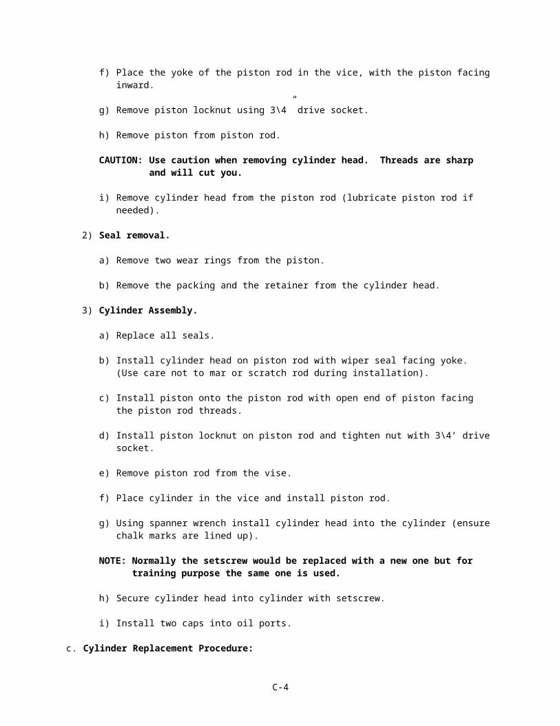
NOTE: Each circuit should have been built as it was interpreted.
C-31

NOTE: Each circuit should have been built as it was interpreted.
C-32

PRESSURE REDUCING CIRCUIT
NOTE: Each circuit should have been built as it was interpreted.
C-33

PRACTICAL EXERCISE SHEET 91L10D05PE2
Title Build a Hydraulic Circuit.
Lesson Number / Title
91L10D05 version 1 / Hydraulic Schematics
Introduction
Motivator Interpreting hydraulic schematics is an important step in learning how to properly troubleshoot and repair a hydraulic system.
Learning Step/Activity
NOTE: The instructor should inform the students of the following Learning Step/Activity requirements. (TLO Step 4)
At the completion of this lesson, you [the student] will:Action: Build a Hydraulic Circuit.
Safety Requirements
Risk of burns, skin and eye injury exists while working with pressurized fluids. Students will wear Personal Protective Equipment (PPE), and relieve hydraulic pressure when working with hydraulic systems at all times. Risk of injury and damage to equipment exists while students operate equipment. Ensure personnel are clear and TMDE is setup IAW the applicable TM prior to starting equipment. Use three points of contact when mounting or dismounting equipment. Remove all jewelry to include ID tags and wedding bands when working on equipment. The location and use of emergency eyewash stations will be identified and demonstrated to students. In case of eye contact with hydraulic fluids, eyewash will be used immediately. Use caution around moving parts. Students will be provided and required to wear PPE while equipment is running. The use of PPE by students and instructors is mandatory. Further guidance concerning PPE can be found in OSHA regulations 29 CFR 1910.132; 29 CFR 1910.133; 29 CFR 1910.136; 29 CFR 1910.138; and 29 CFR 1910.95.
Risk Assessment
Medium - The risk assessment for this module has been reviewed and signed by the responsible officer. Review the deliberate risk assessment, perform a daily risk assessment, and ensure it is recorded on appropriate forms, signed by authorized command authority, and posted at the training site.
Environmental Considerations
Petroleum, Oil and Lubricants (POL) can be hazardous to the environment if not disposed of properly. The possibility exists for the spillage of fuel, oil, and antifreeze during equipment operations. Ensure spill kits are available and there location identified. Adequate ventilation is required during equipment operations in the maintenance shop. Comply with Shop/Installation SOP/Operations order requirements for disposal of hazardous materials. Instructors should complete a risk assessment before conducting training, operations, or logistical activities. Risk assessments assist instructors in identifying potential environmental hazards, develop controls, make risk decisions, implement controls, and ensure proper supervision and evaluation.
Evaluation Practical Exercise
Instructional Lead-In
NOTE: Show Slide #1, Identify the Types and Characteristics of Hydraulic Flow Schematics and Symbols.
NOTE: Show Slide # 2 thru 4
C-34

Introduction of the instructor the topics to be discussed. Inform students of the Terminal Learning Objective (TLO) requirements. State the complete action, conditions, safety and environmental considerations. Explain the importance of understanding and identifying the types and characteristics of hydraulic flow schematics and symbols to properly troubleshoot and repair hydraulic systems.
NOTE: Introduce the lesson topics to be discussed.
a. Identify Hydraulic Schematic Symbols.
b. Identify the Characteristics of Flow in Hydraulic Schematics.
c. Interpret Hydraulic Schematics.
Resource Requirements
Instructor Materials: Hampton Industrial Hydraulics ManualLesson D05
Student Materials: Color MarkersHydraulic Simulator BoardsStudent GuidesHampton Industrial Hydraulics Manual insertsPens and Pencils
Special Instructions
ProceduresBuild a hydraulic circuit using the schematics that were interpreted.
Feedback Requirements
C-35

SOLUTION FORPRACTICAL EXERCISE SHEET 91L10D05PE2
Students should have built a hydraulic circuit using the schematics that were interpreted.
C-36

Appendix D - Student Handouts (N/A)
D-1