cctv 960 instr
TRANSCRIPT


2

3
CCTV-960
Gracias por la compra de este producto Steren.
Esta guia contiene todas las indicaciones necesarias para manejar su nuevo Grabador de video digital de 4 canales con puerto de red.
Por favor, revíse el manual de instrucciones en nuestro sitio web para estar seguro de cómo utilizar apropiadamente el producto.
Para apoyo, compras y todo lo nuevo que tiene Steren, visite nuestro sitio web:www.steren.com.mx
GRABADOR DE VIDEO DIGITAL DE 4 CANALES CON PUERTO DE RED
La información que se muestra en este manual sirve únicamente como referencia sobre el producto. Debido a actualizaciones pueden existir diferencias.
Por favor, consulte nuestra página web (www.steren.com.mx) para obtener la versión más reciente del instructivo.

4
9.1 Grabación Manual 249.2 Grabación programada 25
10. REPRODUCCIÓN Y RESPALDO DE VIDEOS 27
11. INSTALACIÓN DE ALARMA 31
12. PTZ 34Ajustes de cámara PTZ o PT 34Conectar cámaras PTZ o PT 35Usar cámaras PTZ o PT 35
13. CONFIGURACIÓN DE SISTEMA 3813.1 Sistema 3813.2 Grab. 40
14. CONEXIÓN DE RED 50
15. PROBLEMAS Y SOLUCIONES 54
16. ESPECIFICACIONES 54
1. CARACTERÍSTICAS 7
2. CONTROLES 82.1 Panel frontal 82.2 Panel trasero 102.3 Control remoto 12
3. INSTALACIÓN Y USO DEL RATÓN 14
4. CONEXIONES 15
5. FUNCIONES BÁSICAS E INICIO RÁPIDO 17
6. PANTALLA 19Estado de canal: 19
7. BARRAS DE ESTADO Y HERRAMIENTAS 20
8. USO DEL DISCO DURO 228.1 Dar formato al disco duro 228.2 Instalación de disco duro 23
9. GRABACIÓN 24
ÍNDICE

5
IMPORTANTE
• El DVR debe ser operado solamente con el tipo de fuente de alimentación indicado en la etiqueta.
• No instale el DVR cerca de fuentes de calor como radiadores, registros de calefacción, estufas u otros dispositivos semejantes.
• Limpie el CCTV-960 solamente con un paño seco.
• No obstruya las aberturas de ventilación.
• No use ni almacene este equipo en lugares donde existan goteras o salpicaduras de agua. Puede causar un mal funcionamiento o choque eléctrico.
• No coloque objetos pesados sobre el equipo, ni sobre sus accesorios.
• El DVR es un equipo para uso en interiores.
• Hay riesgo de electrocución si una persona no autorizada o califi cada abre la carcasa del DVR.
• Evite la instalación del DVR en un lugar sometido a fuertes movimientos o vibraciones.
• No utilice ni instale el DVR bajo la luz solar directa.
• Asegúrese de que hay una ventilación adecuada alrededor del DVR.
• No inserte ningún objeto en los orifi cios de ventilación.
• No exponga el equipo a temperaturas extremas.
• Compruebe que la electricidad en el lugar donde quiere instalar la unidad de DVR es estable. La electricidad inestable puede provocar averías en la unidad o dañarla gravemente.
• No exponga el equipo ni sus accesorios al polvo, humo o vapor.
• Para desconectar el equipo, jale de la clavija y retírela del contacto. Nunca jale el cable de alimentación para desconectarlo.
6
IMPORTANTE
Seguridad en baterías (del control remoto):
• No utilice a la vez baterías usadas y nuevas o de diferentes tipos.
• Retire las baterías cuando no va a utilizar el control remoto durante un período prolongado.
• Mantenga las baterías fuera del alcance de los niños.
• Si entra en contacto con el material de una batería dañada o con fugas, emprenda las siguientes medidas:
- Si el material le entra en los ojos, no se los frote. Límpielos con abundante agua limpia y acuda inmediatamente con un médico.- Si el material entra en contacto con la piel o la ropa, limpie inmediatamente la zona afectada con agua limpia. Consulte a un médico si observa infl amación o siente dolor.
Recomendaciones de operación:
• Antes de encender el sistema:- Instale el disco duro (más información en la página 23).- Realice todas las conexiones (más información en la página 15).
• Después de encender el sistema:- Espere poco más de 1 minuto para que inicie el sistema.- Inicie la cuenta de administrador para poder visualizar las cámaras.- Formatee el disco duro; de lo contrario, no podrá realizar grabaciones.
• Para iniciar la cuenta del administrador:- Cuando encienda el DVR, se le pedirá que inicie sesión. Seleccione la cuenta “Admin”. La contraseña por defecto es “888888” (seis números ocho); la de Usuarios es”666666”. Para modifi carla consulte el apartado “13. CONFIGURACIÓN DE SISTEMA”.- Una vez conectado aparecerá la pantalla de visualización de cámaras. Cuando haga clic con el botón derecho del mouse o presione MENU en el panel frontal / control remoto, se abrirá la barra de estado. Presione una vez más para abrir la barra de herramientas, en la cual podrá seleccionar el menú principal (PROGRAM) y otras opciones.

7
1. CARACTERISTICAS
IMPORTANTE
• Para salir de la cuenta del administrador:Ingrese al menú principal presionando el botón MENU → Seleccione SALVAR → LOGOUT
• Operaciones básicas:Cambiar el modo de visualización: Use la tecla CUADROS para cambiar al modo de pantalla completa y seleccione con las teclas (CH1 al CH4 en el panel frontal o 1 al 4 en el control remoto) el número de cámara que desea ver.
Las ilustraciones, íconos y pantallas que se muestran en este manual son información de referencia sobre su producto. Debido a actualizaciones pueden existir diferencias.
El grabador digital de 4 canales le permite grabar la señal de 4 diferentes cámaras para circuito cerrado de TV, y a la vez poder monitorear vía Internet por medio de la red.
El video queda almacenado en un disco duro en formato AVI, logrando seleccionar una de las entradas con conector tipo BNC y salida para el monitor.
En el papel frontal encontramos indicadores de encendido y actividad de grabación u operación del disco duro; además incluye controles para seleccionar la cámara que se desea observar en el monitor, también se puede controlar por medio de un control remoto.
8
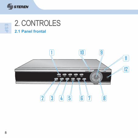
2. CONTROLES2.1 Panel frontal

9
1. CUADROS y CH1 ~ CH4Permiten seleccionar uno de los modos de visualización: Vista simultánea o vista individual.
2. MENUPresione este botón para ingresar al menú principal.
3. ESCPara salir de una ventana o cambiar entre las barras de estado y herramientas.
4. RECInicia o detiene la función de grabación.
5. BackupAbre el menú de búsqueda de video y respaldo.
6. Reproducir / Pausar ( )Abre el menú de búsqueda de video y reproducción. Útil también para pausar una reproducción.
7. PTZAbre los controles de la cámara PTZ.
8. Botones de dirección ◄, ▼, ►, ▲Presione para navegar en menús y submenús.
9. EnterConfi rma operaciones.
10. LED de encendido
11.- LED HDDEnciende para señalar el buen funcionamiento del disco duro y parpadea para indicar que se realiza una grabación.
12. Ventana de infrarrojo
2.1 Panel frontal
10
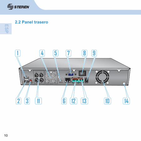
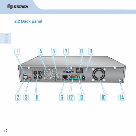
2.2 Panel trasero

11
1. Conector USBConecte dispositivos como memorias USB para realizar respaldos de las grabaciones y confi guraciones de fi rmware.
2. Conector USB de mousePermite conectar un mouse vía USB.
3. Salida de audioConector RCA para salida de audio monoaural.
4. Conectores de entrada de videoConectores BNC para cámaras CCTV.
5. Conector de salida de videoConector BNC de salida de video a un monitor o pantalla.
6. Puerto Ethernet LANUtilice un cable RJ-45 LAN para conectarse a una red LAN.
7. Conector VGAEn este puerto puede conectar un monitor VGA.
8. Interruptor de encendido/apagado.
9. Entrada de alimentación.
10. Ventilador.
11.- Entrada de audioPermite conectar hasta 4 cámaras con micrófono mediante un conector RCA para registro de sonido.
12. Conectores de entrada y salida de la alarma (alarm in/ alarm out).
13. Conector RS-422 / RS-485Permite conectar cámaras PTZ o PT.
14. Tierra.
2.2 Panel trasero

12
2.3 Control remoto

13
1. RECInicia o detiene la función de grabación.
2. Botones alfanuméricosUse estos botones para cambiar de cámara (1 - 4) en modo de vista individual.
3. Permite seleccionar uno de los modos de visualización: Vista simultánea (4) o vista individual.
4. MENU / ESCPara salir de una ventana o cambiar entre las barra de estado y de herramientas.
5. Activa el modo de privacidad.
6. Establece una rotación en la visualización de cada canal.
7. Botones de dirección ◄, ▼, ►, ▲
8. EnterConfi rma operaciones.
9. Sin función.
10. Botón reproducción / pausa ( )Use este botón para reproducir o pausar la reproducción de los videos grabados.
11.- Botón detener ( )Sale de la reproducción del video y regresa al modo de selección de fecha en Playback.
12. Botón retrasar ( )Presione para disminuir la velocidad de la reproducción de 1x a 1/16x.
13. Botón adelantar ( )Presione para aumentar la velocidad de la reproducción de 1x hasta 16x.
14. Compartimento de bateríasPermite colocar dos baterías AAA.
2.3 Control remoto

14
3. INSTALACIÓN Y USO DEL RATÓNPara usar el ratón (mouse) simplemente conéctelo en el puerto USB marcado como MOUSE de la parte posterior.
Visualización de multicámaras:
En la visualización 1 canal haga doble clic sobre la pantalla para ir a la vista multicámaras.
Acceder al menú y confi rmar acción.
Visualización de 1 canal:
Mueva el cursor hasta el canal deseado y haga doble clic izquierdo para visualizar en pantalla completa.
Ver barra de estado y herramientas: En la visualización de cámaras haga clic con el botón derecho para mostrar y ocultar las barras de estado y herramientas.
Cambiar valor: En muchos casos puede utilizar la rueda del ratón para cambiar el valor de alguna opción. Dirija el cursor hasta el valor a modifi car y utilice la rueda para subir o bajar.
Switch 1 canal /multicámaras:
Use el scroll del ratón para intercalar rápidamente entre el modo 1 canal y multicámaras.
Para realizar esta acción deberá encontrarse en el modo multicámaras y seleccionar con doble clic un canal, una vez que ingrese al modo 1 canal deslice el scroll para hacer switch entre visualizaciones.

15
4. CONEXIONES- Conexión de cámarasConecte la salida de video de las cámaras al conector de entrada en la parte posterior del DVR. La interfaz de entrada es un conector BNC.
- Conexiones de audio
• Entrada:La interfaz de entrada de audio es un conector RCA estándar.La señal de audio se debe alejar de fuentes de interferencia como campos magnéticos o eléctricos muy fuertes.
• Salida:Si requiere de una salida de audio, utilice un adaptador BNC a RCA y conecte el DVR a la fuente de sonido externa.
- Conexión de monitor o pantallaConecte una pantalla a la salida BNC o use un monitor en la entrada VGA. Utilice un adaptador BNC a RCA y conecte a la fuente de video externa.
- Conexión de alimentaciónConecte el adaptador de corriente en la entrada de alimentación que se encuentra en el panel trasero.
- Conexión a red EthernetConecte un cable de red al conector RJ-45 para tener acceso remoto vía Internet o Ethernet.

16
USB
MOUSE
IN2
IN1
CH1
CH2
CH3
CH4IN3AUDIO IN VIDEO IN
MAIN OUT LAN
VGA
DC 12V
POWER
ALARMIN
1 2 3 4 G G TX+
TX-
TX+
TX-
- +
ALARMOUT
RS422
IN4
AUDIOOUT
En caso de ser necesario, use adaptadores (con conector hembra RCA a conector macho BNC) en las conexiones de audio y video.
- Conexión USBEn el puerto USB puede conectar unidades de respaldo como memorias USB.
- Conexión de cámaras PTZ o PTDe acuerdo a su polo inserte los cables RS485 de la cámara en las entradas RX y TX.
4. CONEXIONES

17
5. FUNCIONES BÁSICAS E INICIO RÁPIDOEncienda el DVR y espere a que inicie el sistema. El DVR emitirá un sonido y mostrará el mensaje “¡No disco!” si no se ha instalado un disco duro o “Ilegal sistema archivo necesita formato!” si ya ha conectado uno. Al iniciar el sistema aparecerá la ventana de inicio de sesión que le pedirá una cuenta de usuario para operar el DVR. La contraseña por defecto para la cuenta “Admin” es “888888”. En la parte inferior de la pantalla se mostrará la barra de estado. Presione el botón derecho del mouse o presione [ESC] en el DVR o control remoto para cambiar a la barra de herramientas que le permitirá ajustar los parámetros y operar el DVR.
Para ingresar al Menú principal, presione el botón MENU en el DVR / control remoto o en la barra de herramientas. Después oprima PROGRAM.
• ESTADO:
• HERRAMIENTAS:
• MENÚ PRINCIPAL:

18
Si no ha instalado un disco duro en el CCTV-960, éste comenzará normalmente, pero sólo podrá ser usado para monitorear, no para grabar.
Después de esto, el sistema mostrará la vista de los 4 canales en vivo:
- Apagado:No apague el DVR mientras está grabando.
Presione el botón derecho del mouse o presione [ESC] en el DVR / control remoto para abrir la barra de herramientas y seleccione el botón ENCENDER.
Ingrese la contraseña del usuario correspondiente. Una vez que desaparezca la imagen de la pantalla y que los LEDs indicadores dejen de parpadear, use el interruptor de encendido y apagado para desactivar el DVR.
5. FUNCIONES BÁSICAS E INICIO RÁPIDO

19
6. PANTALLALa visualización de la pantalla puede ser de dos modos:
• Vista simultánea.• Vista individual.
También se puede seleccionar una cámara presionando las teclas 1-4 del panel frontal del DVR.
Indica detección de movimiento. Aparece cuando las cámaras perciben movimientos.
(Azul): Indica que se realiza una grabación por horario.
(Verde): Indica grabación accionada por detección de movimiento.
(Rojo): Indica grabación accionada por la alarma.
(Gris): Indica que se realiza una grabación manual. Aparece cuando se presiona REC y el DVR no tiene ninguna confi guración de grabación (evento, horario, alarma).
Para más información sobre cómo ajustar los tipos de grabación, consulte la sección 9 “Grabación”.
TIP: Puede usar la rueda del ratón para intercalar rápidamente entre la vista individual y simultánea. Para realizar esta acción deberá encontrarse en la vista simultánea y seleccionar un canal con doble clic. Una vez que ingrese a la vista individual deslice la rueda para cambiar entre las visualizaciones.
Estado de canal:
20
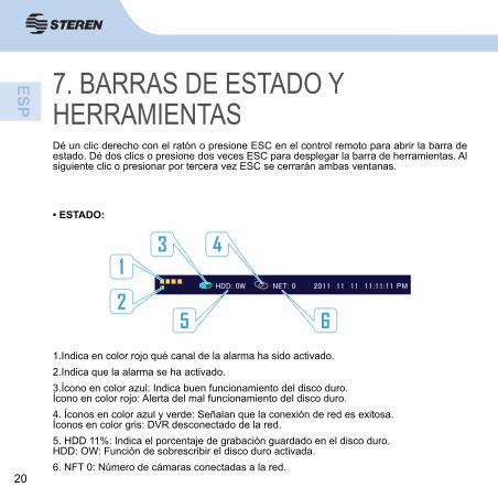
7. BARRAS DE ESTADO Y HERRAMIENTASDé un clic derecho con el ratón o presione ESC en el control remoto para abrir la barra de estado. Dé dos clics o presione dos veces ESC para desplegar la barra de herramientas. Al siguiente clic o presionar por tercera vez ESC se cerrarán ambas ventanas.
1.Indica en color rojo qué canal de la alarma ha sido activado.2.Indica que la alarma se ha activado.3.Ícono en color azul: Indica buen funcionamiento del disco duro.Ícono en color rojo: Alerta del mal funcionamiento del disco duro.4. Íconos en color azul y verde: Señalan que la conexión de red es exitosa.Íconos en color gris: DVR desconectado de la red.5. HDD 11%: Indica el porcentaje de grabación guardado en el disco duro.HDD: OW: Función de sobrescribir el disco duro activada.6. NFT 0: Número de cámaras conectadas a la red.
• ESTADO:
21
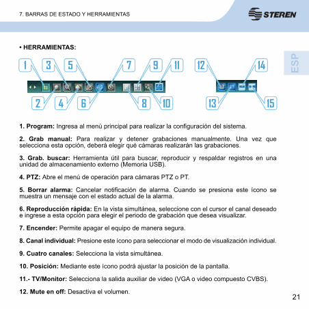
1. Program: Ingresa al menú principal para realizar la confi guración del sistema.
2. Grab manual: Para realizar y detener grabaciones manualmente. Una vez que selecciona esta opción, deberá elegir qué cámaras realizarán las grabaciones.
3. Grab. buscar: Herramienta útil para buscar, reproducir y respaldar registros en una unidad de almacenamiento externo (Memoria USB).
4. PTZ: Abre el menú de operación para cámaras PTZ o PT.
5. Borrar alarma: Cancelar notifi cación de alarma. Cuando se presiona este ícono se muestra un mensaje con el estado actual de la alarma.
6. Reproducción rápida: En la vista simultánea, seleccione con el cursor el canal deseado e ingrese a esta opción para elegir el periodo de grabación que desea visualizar.
7. Encender: Permite apagar el equipo de manera segura.
8. Canal individual: Presione este ícono para seleccionar el modo de visualización individual.
9. Cuatro canales: Selecciona la vista simultánea.
10. Posición: Mediante este ícono podrá ajustar la posición de la pantalla.
11.- TV/Monitor: Selecciona la salida auxiliar de video (VGA o video compuesto CVBS).
12. Mute en off: Desactiva el volumen.
• HERRAMIENTAS:
7. BARRAS DE ESTADO Y HERRAMIENTAS

22
13. Congelamiento de la pantalla: Presione para congelar la imagen visualizada. Presione de nuevo para desactivar esta función.
14. PIP 1X1: Permite la visualización de un canal en pantalla completa y uno más en pantalla pequeña. Para seleccionar el canal a visualizar simplemente dé clic sobre el canal deseado.
15. PIP 1X2: Permite la visualización de un canal en pantalla completa y dos más en pantalla pequeña. Para seleccionar los canales a visualizar simplemente dé clic sobre ellos.
8. USO DEL DISCO DURO
Antes de realizar cualquier grabación es necesario formatear el disco duro: 1. Inicie sesión como Admin e introduzca la clave de fábrica “888888”. 2. Presione MENU en el control remoto / panel frontal del DVR o dé doble clic derecho con el ratón para ingresar a la barra de herramientas y seleccione [Program].3. Ingrese a [Manutención] → [ADM. HDD]
8.1 Dar formato al disco duro

23
Todo el contenido del disco será eliminado cuando sea formateado.Al formatear el disco duro NO se perderá ningún tipo de ajuste como confi guración de grabación, usuarios y contraseñas establecidas en el CCTV-960. Únicamente se eliminarán los videos y datos extra contenidos en el disco duro.
3. Haga clic en [>>] para abrir la ventana de administración del disco duro. 4. Se mostrará la información del disco duro. Haga clic en [De formato] para iniciar el formateo del disco duro.5. Espere a que el proceso termine y seleccione [Salir] para regresar al menú principal.
1. Retire los tornillos (4 laterales y 3 posteriores) de la cubierta del DVR y jale hacia fuera.
2. Conecte el cable plano SATA a su disco duro, asegúrese de que la pestaña ubicada a un lado del cable coincida con la ranura del disco duro, de otra forma no podrá conectar el cable.
3. Conecte el cable de energía al disco duro.
4. Coloque el disco duro en el interior del DVR. Para asegurarlo, atornille en cada lado del disco duro.
5. Vuelva a colocar la cubierta del equipo atornillando fi rmemente para asegurarla.
8.2 Instalación de disco duro
8. USO DEL DISCO DURO

24
9. GRABACIÓN Para iniciar la grabación es fundamental que haya instalado y formateado el disco duro,
de lo contrario sólo estará limitado a la visualización de cámaras.
El DVR tiene 2 métodos de grabación:
9.1 Grabación ManualEste modo de grabación es usado cuando el DVR no tiene ninguna confi guración de grabación (evento, horario o alarma).
Para detener la grabación, pulse el botón REC (panel frontal / en el control remoto) o deseleccione los canales que realizan grabaciones.
CH1
MENU ESC REC
CH2 CH3
BACKUP
• Opción 2: Presione [MENU] en el control remoto / panel frontal del DVR o dé doble clic con el ratón y seleccione [Grab. Manual] en la barra de herramientas.
Una vez que aparezca la siguiente ventana, seleccione los canales que realizarán grabaciones y confi rme con [OK].
• Opción 1: Pulse en cualquier momento el botón [REC] del panel frontal o en el control remoto. Aparecerá el indicador gris en los canales activos y el LED rojo comenzará a parpadear, señalando el estado de grabación.
Pulse [REC] nuevamente para detener la grabación.

25
9.2 Grabación programada1. Para comenzar a programar grabaciones acceda al menú principal y seleccione [Grab.]
2. En la opción CA VIDEO, seleccione el número del canal al que desea aplicar la programación (1, 2, 3, 4 ó todo)
3. Seleccione [>>] en la opción ITIN. GRAB para abrir la ventana de horario.
- No grab. (No grabar): Para cancelar todo tipo de grabación programada marque las casillas de hora en color blanco. Esta modalidad es útil si desea usar el CCTV-960 únicamente para monitorear.
- Grab. común (Horario): Esta opción programa el horario de grabación, es decir, el CCTV-960 comenzará a grabar cuando alcance la hora y el día confi gurado.
- Grab. Mov. c Alarma (Evento): Inicia la grabación cuando se presenta un evento (detección de movimiento o activación de alarma).
- Grab. moción: Indica que la grabación será accionada cuando exista detección de movimiento. Tome en cuenta que la sensibilidad puede ser ajustada.
- Grab. alarma: Inicia la grabación cuando se activa la alarma.
4. En pantalla se mostrará una cuadrícula. Cada fi la horizontal es un día de la semana y cada cuadro una hora.En las casillas de colores ubicadas en la parte inferior, seleccione la modalidad de grabación que se aplicará. A continuación se presenta el signifi cado de los colores:
10. GRABACIÓN

26
5. Una vez que seleccionó el tipo de grabación, puede hacer clic en las casillas que desea aplicar la confi guración.
6. Confi rme seleccionando OK. Ahora el DVR está programado para realizar grabaciones en el horario marcado. En caso de que desee detener la grabación, deberá ingresar a este menú y deseleccionar las casillas necesarias con la modalidad No. grab.
TIPS: En este menú también puede usar las teclas de dirección (para navegar) y ENTER (seleccionar) del CCTV-960 ó del control remoto.- Si presiona el botón de un día podrá marcar todas las horas.
9. GRABACIÓN

27
10. REPRODUCCIÓN Y RESPALDO DE VIDEOS
1. Para comenzar con la reproducción de grabaciones deberá ingresar al menú Grab. buscar (explorador de registros). Existen dos modos:
A) Presione el botón REPRODUCIR / PAUSA del DVR o del control remoto.
B) Dé doble clic con el botón derecho del ratón para abrir la barra de herramientas y seleccione [Grab. buscar].
2. Utilice las fl echas ▼, ▲ para seleccionar el año, mes y día que quiere explorar.
3. Seleccione los canales en los que desea realizar la búsqueda y seleccione [Buscar]. Los resultados de los registros se mostrarán en la pantalla con diferentes colores para indicar el tipo de grabación.
4. Cuando aparezcan los archivos de la fecha seleccionada, use para acercar o alejar la línea de tiempo.
- Si la parte de la línea de tiempo que busca se encuentra fuera de la pantalla, utilice los botones - Si la parte de la línea de tiempo que busca se encuentra fuera de la pantalla, utilice los
.
Ventana del Explorador de registros.

28
5. Después de terminar la búsqueda, deberá elegir un extracto a reproducir.
Seleccione el inicio haciendo clic con el botón izquierdo sobre la línea de tiempo. También marque el fi n haciendo nuevamente clic. Note que la duración seleccionada se indicará con dos líneas de color rosa. Para deseleccionar simplemente dé doble clic derecho con el ratón.
6. Presione [Reprod.] para confi rmar la selección. La reproducción de grabaciones comenzará automáticamente.
7. Se mostrarán los controles y la reproducción de los canales que realizaron grabaciones. En caso de que desee visualizar solamente un canal, selecciónelo con doble clic.
Se puede seleccionar una cámara presionando las teclas 1-4 del panel frontal del DVR o del control remoto.
1. Pulse este botón para retroceder durante la reproducción 1x, 8X y 16x.
2. Seleccione este botón para reanudar la reproducción luego de haber presionado pausa.
• Controles de reproducción:
10. REPRODUCCIÓN Y RESPALDO DE VIDEOS

29
4. Pulse este botón para que la reproducción sea más rápida que la velocidad normal 1x, 2x, 4x, 8x, 16x, 1/8 x, ¼x, ½x.
5. Presione este botón repetidamente para visualizar un registro paso a paso.
6. Presione para cambiar entre la vista individual y simultánea.
7. Esta herramienta es útil para exportar a un dispositivo de almacenamiento USB un recorte de video. Cuando decida iniciar con el recorte dé clic en este botón (tijeras). Note que la herramienta de tijeras se torna de color rojo. Una vez que desee fi nalizar el corte presione nuevamente, el ícono volverá a su color normal (azul).
Recuerde, sólo se realizará el recorte del canal que haya seleccionado en el explorador de registros.
8. Sirve para exportar el recorte de video previamente seleccionado con la herramienta de tijeras. Ingrese a esta opción (diskette), conecte un dispositivo de almacenamien-to USB en el panel trasero del DVR, seleccione el video que desea guardar y dé clic en el botón [Repuesto].
El DVR le informará cuando se haya exportado el video. Finalmente consulte el archivo en cualquier computadora.
8. Para detener y salir seleccione el botón de detener.
9. Si desea exportar el extracto seleccionado, conecte un dispositivo de almacenamiento USB en el puerto trasero del DVR y elija el botón [Repuesto].
A continuación escoja el formato en que será exportado el video (MP4, AVI, H264Roh). Finalmente dé clic en el botón [Repuesto].
Espere a que los archivos se guarden en su dispositivo USB, se mostrará una línea de progreso. El CCTV-960 emitirá una alerta sonora y confi rmará con mensaje de pantalla la fi nalización de la exportación.
10. REPRODUCCIÓN Y RESPALDO DE VIDEOS

30
Espere a que los archivos se guarden en su dispositivo USB, se mostrará una línea de progreso. El CCTV-960 emitirá una alerta sonora y confi rmará con mensaje de pantalla la fi nalización de la exportación.
Retire el medio de almacenamiento externo (USB) y conéctelo a su computadora.
Abra en su computadora el medio de almacenamiento externo (memoria USB) para buscar los archivos exportados. Recuerde que el nombre del video será el mismo que el DVR le asignó. A continuación un ejemplo y su descripción:
3-20120913091500Canal- Año/Mes/Día Hora/Minuto
Si el tamaño del video es muy grande, la exportación podría tardar varios minutos.
10. REPRODUCCIÓN Y RESPALDO DE VIDEOS

31
11. INSTALACIÓN DE ALARMA1. Observe el siguiente diagrama de conexión para poder usar el CCTV-960 con una alarma:
2. En el DVR ingrese a PROGRAM > ALARMA > CA ENT. ALARMA y seleccione la entrada de alarma (1 al 4 ó todo) que desea confi gurar.
3. Seleccione un modo de operación de alarma para el canal seleccionado:
- N.O.: Normalmente abierto. El sensor debe tener una salida constante de nivel de voltaje bajo. Si la salida de voltaje cambia de un nivel bajo a un nivel alto el DVR se activará.
- N.C.: Normalmente cerrado. El sensor debe tener una salida constante de nivel de voltaje alto. Si la salida de voltaje cambia de un nivel alto a un nivel bajo el DVR se activará.

32
-SALIDA AL: activar alarma externa.-CAMPA: activar timbre del DVR.-CARGA: seleccione para enviar un mensaje al applet del explorador cuando se active la alar-ma. El mensaje se visualizará en la esquina superior derecha de la pantalla de la ventana del explorador. (Requiere una conexión remota establecida entre el DVR y una PC vía Internet).-Email: advertencia a mail.-FTP Upload Imagen: transmite imágenes a un servidor FTP cuando un evento es activado.
6. Alarma alejar: si activa la función “Alarma alejar” en la opción Manejo eventos, esta opción ajusta el tiempo (en segundos) de salto en la visualización de pantallas.
5. Seleccione la opción Ajuste de alarma y establezca el horario deseado para activar o desactivar la opción de alarma.
COLOR ROJO: Activa la función de alarma.
COLOR BLANCO: Desactiva la función de alarma.
4. En la opción Manejo de eventos seleccione las actividades que realizará el DVR cuando la alarma sea activada:
-Grab: selecciona el número de canal que comenzará a grabar cuando se active la alarma.-PROG. PTZ: establece la posición PTZ predefi nida para los canales seleccionados.-ALARMA ALEJAR: permite la visualización en pantalla completa de los canales seleccionados.
11. INSTALACIÓN DE ALARMA

33
7. Vinculación anormal del equi: esta opción permite seleccionar las alarmas y advertencias que activará el CCTV-960 al detectar uno de los siguientes eventos.
- Completo HDD: si el disco está lleno, el sistema le avisará de acuerdo a las advertencias seleccionadas.- Desconexión de red: las alarmas seleccionadas se activarán si hay una desconexión.- Impacto de IP: si hay un confl icto de direcciones IP dentro de la misma red, el dispositivo activará las alarmas confi guradas.

34
Ajustes de cámara PTZ o PTAcceda al menú MENU DE HERRAMIENTAS > VIDEO para confi gurar los parámetros del DVR (los parámetros deberían ser los mismos que la cámara PTZ o PT).
1. En el campo CA Cámara, seleccione el canal del DVR donde conectará la cámara PTZ o PT.
2. En PROTOCOLO PTZ, seleccione el protocolo del DVR de acuerdo a su cámara. Importante, estos valores deben ser los mismos entre la cámara y el CCTV-960.
3. Según sus necesidades en TASA BAUDIO PTZ, seleccione el mismo valor de Baud rate (Velocidad de baudios) tanto en la cámara como en el DVR, las opciones son: 1200, 2400, 4800 y 9600.
4. Seleccione la dirección (ID PTZ) que tiene establecida la cámara PTZ o PT. Elija un número del 0 al 255. Presione los botones de fl echa para seleccionar un valor.
Si desea conectar otra cámara simplemente seleccione una dirección y canal diferente.
12. PTZ
12. PTZ

35
Conectar cámaras PTZ o PTInformación importante antes de comenzar:
- Presione los seguros de este puerto con ayuda de un desarmador para poder conectar y asegurar los cables RS485 de las cámaras.- Los cables RS485 de la cámara PTZ o PT son los que permiten la comunicación del DVR generalmente está marcado de color morado el positivo (+) y de gris el negativo (-). Para más información consulte las especifi caciones de su cámara.
Usar cámaras PTZ o PT1. Una vez conectada la cámara abra el menú de control, existen dos modos:
a) En la pantalla de visualización de canales, presione dos veces el botón derecho del ratón para ingresar a la barra herramientas y seleccione la opción PTZ.b) Presione el botón PTZ en el panel frontal del DVR.
1. Inserte los cables RS485 de la cámara en las entradas RX y TX en el panel trasero del DVR de acuerdo a su polo.
2. Conecte el cable de la cámara al canal que seleccionó en el paso 1 de las instrucciones “Ajustes de cámara PTZ o PT”. En caso de ser necesario use un adaptador con conector hembra RCA a conector macho BNC.
3. Inserte el eliminador al conector de alimentación de la cámara para energizarla.
12. PTZ

36
2. Cuando observe la pantalla de visualización, mueva el ratón para operar la cámara PTZ o PT.
3. En el campo superior seleccione la velocidad con la que operará la cámara. En caso de que su cámara cuente con funciones de Zoom, Foco e Iris ajústelas según lo necesite.
4. Para abrir los controles extendidos haga clic con el botón ▼.
- Auxiliar: permite controlar funciones especiales de la cámara PTZ o PT conectada. Esta función operará de diferente modo dependiendo el protocolo usado.
- Pre-ajust: útil para fi jar y usar punto predeterminado (Preset).En este campo seleccione el número de identifi cación deseado y use el mouse para ir a la posición deseada, confi rme el punto dando clic en ► . Para usar un punto predeterminado simplemente seleccione el botón .
- Crucero: Para programar una ruta de rastreo.
En este campo seleccione . En el campo Pre-ajuste seleccione el punto de referencia que desea agregar y confi rme con Dir. Para agregar más puntos repita este proceso, note que en la parte inferiror se muestra la ruta de crucero programada. Dé clic en Salvar para guardar y salir.
12. PTZ

37
- Huella: esta opción permite realizar una grabación de una ruta. Ingrese seleccionando el botón de confi guración y dé clic en Iniciar el registro de huella para comenzar la grabación. Mueva el mouse para controlar la cámara, para detener la grabación de la ruta ingrese a esta opción nuevamente y seleccione Terminar registro de huella y fi nalmente OK. Para usar la Huella simplemente seleccione el botón ingrese a esta opción nuevamente y seleccione Terminar registro de huella y fi nalmente OK.
.
Las funciones Auxiliar y Huella pueden responder de diferentes maneras o quedar inactivas dependiendo de la cámara PTZ o PT utilizadas.
12. PTZ

38
13. CONFIGURACIÓN DE SISTEMADespués de instalar el DVR y las cámaras, podrá realizar los principales ajustes con la opción PROGRAM de la barra de herramientas; para ingresar a este menú existen tres modos:
a) Presione el botón derecho del ratón en la pantalla de visualización de canales y seleccione la opción SET.b) Presione el botón MENU en el panel frontal del DVR.c) Presione el botón MENU de control remoto.
El apartado SET se conforma de 6 menús principales que a su vez contienen submenús de ajustes.
13.1 Sistema En este menú podrá confi gurar los ajustes principales y avanzados del CCTV-960.
- Lenguaje/Idioma: cambia el idioma del menú del DVR y el idioma de los textos en pantalla.- Video Padrón: selecciona la norma de video del CCTV-960 ( NTSC, SECAM o PAL). Para México y EUA use NTSC. El sistema de video por defecto del DVR es “NTSC”. El cambio es efectivo después de guardar y salir del menú.- Prog. YGA: cambia entre las diferentes resoluciones de salida VGA, las opciones son 1024x768@60Hz, 1280x1024@60Hz, 1440x900@60Hz,800x600@60Hz- Formato tiempo: cambia el formato de hora entre 12 y 24 horas.- Prog. Horas: ajusta los valores de Fecha y Hora. A fi n de evitar confusiones de los archivos grabados, es mejor detener la grabación antes de modifi car la hora y fecha.- DST: (Horario de verano): En este apartado puede habilitar (Enable) o deshabilitar (Disable) el horario de verano. Confi gure la fecha de inicio y la fecha de fi nalización de acuerdo a su región.Es recomendable que ajuste la hora y la fecha correcta del horario de verano, pues en caso de que necesite comprobar algún acontecimiento crucial esto brindará veracidad al video captado por el CCTV-960.

39
- HDD sobrescribir (Sobrescribir disco duro): permite activar o desactivar la modalidad reutilización de espacio en disco. Encend: de este modo se activa la función sobrescribir, es decir, cuando el disco duro esté lleno, se empezarán a sobrescribir los datos más antiguos.Apag.: la grabación se detendrá cuando el disco duro esté lleno.- Dir. user: útil para agregar un nuevo usuario al sistema. Use el teclado para introducir la información del usuario y haga clic en OK para guardar. El número máximo de usuarios que se pueden crear en el DVR es 7, pero sólo uno puede ser ADMINISTRADOR (Admin).
Importante: para agregar usuarios deberá iniciar sesión en el CCTV-960 con la cuenta Admin.- Del. user: elimina un usuario del sistema. Seleccione el nombre del usuario y haga clic en Del (Borrar).- Buscar usuario en red: el sistema mostrará los detalles de las conexiones actuales.- ADMIN AUTORIDAD: use para confi gurar la autoridad local y remota para tener acceso a funciones seleccionadas del sistema. Predeterminadamente, sólo la cuenta Admin tiene permiso para modifi car los ajustes del DVR.En la ventana de opciones de autoridad, haga clic en los cuadros para conceder esa autoridad al usuario. Haga clic en OK para confi rmar.- PROG. CLAVE: use para cambiar las contraseñas de usuario/administrador.- Código de equipo: permite establecer un número de identifi cación para reconocer el DVR en conexiones remotas.
- Vista previa crucero: selecciona el tiempo para la vista de canales en secuencia, las opciones son 2, 5, 10, 15 ó 20 s.
- Horas extras de menú: esta opción permite bloquear el equipo luego de estar inactivo. Para ingresar al sistema deberá ingresar su contraseña.
- Confi g. de bloqueo de canal: sin función.
13. CONFIGURACIÓN DE SISTEMA

40
13.2 Grab.Contiene todo lo referente a los horarios y calidad de grabación.- CA VIDEO: seleccione el canal de cámara para aplicar las confi guraciones correspondientes. Seleccione “Todo” para aplicar a todos los canales. - ITIN GRAB: en este apartado se puede ajustar un horario de grabación, consulte la sección 9. GRABACIÓN para más información.- CALID GRAB: seleccione el nivel de calidad para grabar audio / video. Las opciones son Mejor (768kbps), Alta (640Kbps), Media (512kbps), Baja (384kbps) o defi nido por el usuario. - TASA EXP. GRAB: ajusta la medida de la frecuencia a la cual se generarán los fotogramas (frames), las opciones son 1, 3, 7 y 15 FPS, Todo (30/25FPS) o defi nido por el usuario. Para la opción defi nida por el usuario, haga clic en el botón >> para tener acceso al teclado numérico. Introduzca el valor de la calidad de la grabación y dé clic en OK para aceptar los cambios.- FRENTE GRAB: selecciona la modalidad de grabacion, video y audio o unicamente registro de video.- PROG. OSD: defi na la información que se grabará como la cadena OSD (visualización en pantalla). Las opciones son: marca de Nombre de sello de tiempo de la Cámara, Nombre de la Cámara, Sello de Tiempo o Ninguno. Use los botones de fl echa para seleccionar una opción.- RESOLUCIÓN GRAB: selecciona la resolución de la grabación, las opciones son: CIF(352 x 240 ó 352 x 288), Half D1(704 x 240 ó 704 x 288) y D1(704 x 480 ó 704 x 576). Predeterminadamente el CCTV-960 tiene ajustado el formato de video CIF.
- SUB CÓDIGO (código secundario): el DVR puede transmitir información para ser vista usando el explorador IE.
Puede activar/desactivar (ENCEND/APAG) el código secundario o crear ajustes personalizados presionando el botón >> para ajustar los valores de cuadros por segundo (fps) y la velocidad de bits (Kbit/s).
13. CONFIGURACIÓN DE SISTEMA

41
13.3 Video Haga clic en el botón Video en el menú Confi guración del Sistema para tener acceso a las opciones de los ajustes Camera (Cámara) y personalizar los ajustes para cámaras PTZ*/estándar y ajustar la calidad, la detección de movimiento y las zonas de privacidad.
CA CÁMARA: Selecciona el canal al que se le aplicaran los ajustes. Haga clic en los botones de fl echa para seleccionar el canal 1, 2, 3, 4 ó Todo.
PROTOCOLO PTZ: Opción que permite seleccionar el protocolo según los parámetros confi gurados en la cámara domo (PT o PTZ).
Antes de cambiar protocolos PTZ, seleccione el número de canal (cámara) correcto en el campo CA CÁMARA.
TASA BAUDIO PTZ: Permite elegir la velocidad de los baudios (1200, 2400, 4800,9600).
ID PTZ: Selecciona la ID del dispositivo PTZ, asegúrese de ajustarlo de acuerdo a la ID de las cámaras PTZ. Elija un número del 0 al 255. Presione los botones de fl echa para seleccionar un valor. Los cambios son efectivos después de guardar y salir del menú.
PROG. COR: Ajusta los atributos de color de la cámara (brillo, contraste, matiz, y saturación) para la mejor visualización de la imagen. Haga los ajustes dependiendo de las condiciones en el lugar donde está instalada la cámara.
DETECCIÓN MOVIMIENTO: Confi gure la sensibilidad de detección de movimiento y confi gure manualmente las zonas para detección de movimiento. Use las fl echas < > para seleccionar una de las cuatro opciones de sensibilidad.
13. CONFIGURACIÓN DE SISTEMA

42
Dé clic en el botón >> para ingresar a más opciones
- Zona de Detección de Movimiento: Haga clic en los bloques y arrastre presionando el botón (izquierdo) del ratón. El color azul indica área efectiva para detección, transparente signifi ca inhabilitado. Haga clic con el botón derecho del mouse para guardar cambios y salir.
- Planifi cación de movimiento: Abre una ventana adicional para confi gurar el horario en que se activará esta función.
Presione el botón izquierdo del mouse o las teclas de dirección y ENTER en el DVR o control remoto hasta marcar el color del tipo activación en las casillas de hora y día, a continuación se presenta el signifi cado de los colores.
*COLOR ROJO: Activa la función de alarma.*COLOR BLANCO: Desactiva la función de alarma.
13. CONFIGURACIÓN DE SISTEMA

43
MOSAIC: Cada cámara puede defi nir regiones múltiples para protección de privacidad, es decir, en pantalla aparecerán bloques que censurarán un área establecida en la vista de canales.
Para agregar oprima y mantenga presionado el botón izquierdo del mouse y seleccione el área, para borrar máscaras selecciónelas con el botón derecho. Cada región de privacidad se mostrará de color azul cuando realice una grabación.
Las máscaras colocadas sólo se verán durante el proceso de visualización de pantallas en vivo y mientras graba, pero no quedarán registradas en el video fi nal.
MANEJO MOVIMIENTO: Esta opción permite seleccionar el tipo de aviso que se activará en caso de que ocurra un evento (Detección de movimiento).
- Grab.: seleccione las cámaras que desea activar para esta aplicación.
- ALARMA ALEJAR: permite la visualización en pantalla completa de los canales seleccionados.
- SALIDA AL: activar alarma externa.
- CAMPA: activar timbre del DVR.
- CARGA: seleccione para enviar un mensaje al applet del explorador cuando se detecte movimiento. El mensaje se visualizará en la esquina superior derecha de la pantalla de la ventana del explorador. (Requiere una conexión remota establecida entre el DVR y una PC vía Internet).
- Email (advertencia a mail): Envía un correo electrónico a la dirección confi gurada.
13. CONFIGURACIÓN DE SISTEMA

44
Tratamie. de pérdida video: Esta aplicación permite activar una advertencia en caso de que se presente una pérdida de video.
- SALIDA AL: activar alarma externa.- CAMPA: activar timbre del DVR.- CARGA: Seleccione para enviar un mensaje al applet del explorador cuando se detecte pérdida de video. El mensaje se visualizará en la esquina superior derecha de la pantalla de la ventana del explorador. (Requiere una conexión remota establecida entre el DVR y una PC vía Internet).- Email (advertencia a mail): Envía un correo electrónico a la dirección confi gurada.
CANAL DE NOMBRE: Haga clic en el botón >> para visualizar el nombre del canal. Introduzca o cambie el nombre del canal usando el teclado. Haga clic OK para guardar el nuevo nombre.
13. CONFIGURACIÓN DE SISTEMA

45
13.4 RedEl DVR soporta dos opciones para visualizarlo en línea después de ajusta una direcciónde IP:
- DHCP (modo automático). Adquiera la dirección de IP usando el modelo de cliente DHCP.
- IP Estática (modo manual). Indique la dirección de IP usando el modelo de IP estática (introduzca los datos para los campos Direc IP, Máscara Subred y Puerta (Gateway).
Nota: Para obtener información específi ca para su red y una explicación de los ajustes de la red, contacte con su administrador de red o proveedor de servicios de Internet.
PUERTO HTTP: El puerto HTTP conecta al servidor de web del DVR. De forma predeterminada, el valor es 87. De ser necesario, puede especifi car un número de puerto diferente.
PUERTO DE COMANDO: El puerto de comando controla el DVR. De forma predeterminada, el valor es 5050. De ser necesario, puede especifi car un número de puerto diferente.
PUERTO DE MEDIA: El puerto de medios se usa para transferencia de audio y video. De forma predeterminada, el valor es 6050. De ser necesario, puede especifi car un número de puerto diferente.
Prog. PPPOE: Use las teclas de fl echa para activar/desactivar (ENCEND/APAG) el ajuste PPPoE. Los cambios son efectivos después de guardar.
Haga clic en el botón >> para tener acceso a la ventana de Ajustes. Use el teclado, introduzca el nombre de cuenta y la contraseña de usuario. Estos datos puede obtenerlos con su proveedor de servicio de Internet.
IP PPPOE: los valores PPPoE IP se basan en su cuenta de Internet. Para los detalles, póngase en contacto con su proveedor de servicio de Internet.
DIRECCIÓN DNS: Coloque el cursor sobre un valor y use el teclado emergente para introducir su dirección DNS.
13. CONFIGURACIÓN DE SISTEMA

46
DDNS: haga clic en la fl echa para activar (ENCEND) o desactivar (APAG) la opción DDNS. Cuando está activada, haga clic en el botón >> para tener acceso a la ventana de ajustes DDNS y ajustar Servidor DDNS, Nombre y Clave. Para los detalles, póngase en contacto con su proveedor de servicios de Internet.
Haga clic en >> para tener acceso a la ventana de ajuste de correo electrónico. Use el teclado para introducir las direcciones de correo electrónico de las personas que necesitan recibir notifi caciones de alarma.
Introduzca el nombre de usuario y la contraseña de la cuenta de correo electrónico que enviará los correos electrónicos de notifi cación e indique los detalles de Servidor y Puerto.
AUTO REGISTER (REGISTRO AUTOMÁTICO): Haga clic en la fl echa para activar (ENCEND) o desactivar (APAG) la opción Auto Register.
Cuando está activada haga clic en el botón >> para tener acceso a la ventana de ajustes Registro Automático y ajustar el IP Servidor, Puerto Servidor e Intervalo. Para los detalles, póngase en contacto con su proveedor de servicios de Internet.
Introduzca la dirección de correo electrónico de la persona que necesita recibir el correo electrónico.
13. CONFIGURACIÓN DE SISTEMA

47
Para activar notifi caciones por correo electrónico disparadas por alarma, las funciones deben ajustarse en el menú Alarma.
Haga clic en el botón VER para tener acceso a la lista de direcciones de correo electrónico de quienes recibirán el correo electrónico. Haga clic en el botón Del. para eliminar una dirección de la lista. Haga clic Borr. todo para eliminar todas las direcciones de la lista.
Haga clic en OK para guardar los cambios. Haga clic en Annulla para salir de la ventana sin guardar.
Teléfono puerto: el DVR permite acceso remoto desde un teléfono móvil. Se indica el puerto que usa el teléfono móvil (de forma predeterminada es 7050).
- UPnP: el usuario puede seleccionar UPnP y habilitar la función UPnP en el router del usuario para poder acceder al DVR a través de la WAN.
- FTP servidor: transmite imágenes a un servidor FTP cuando un evento es activado (movimiento o sensor).
Presione >> para confi gurarlo. Servidor: Ingrese la dirección IP, Nombre: En este campo debes introducir el nombre del servidor, Puerto: Ingrese el número de Puerto FTP, ID: Ingrese ID y Clave: Ingrese la contraseña.
13. CONFIGURACIÓN DE SISTEMA
Consulte el apartado 11. INSTALACIÓN DE ALARMA para más información de este menú.13.5 Alarma

48
- Vista reg: haga clic en el botón >> para abrir la pantalla de Registros. En el campo Tipo selecciona una de las siguientes opciones: Todo, Operación, Excepción y Alarma.
En el campo Tiempo buscar, introduzca la fecha y la hora para buscar el registro.
Haga clic en el botón Buscar para visualizar el registro o registros deseados. Dependiendo del tamaño y la cantidad de los registros puede que tome varios minutos para rellenar la lista.
La primera columna es el tiempo de inicio de un evento en el formato AAAAMMDD HHMMSS. La segunda columna es la descripción de los eventos.
Si en una ventana no caben múltiples eventos, haga clic en el botón Prev. (Anterior) o Seg. (Siguiente) en la parte inferior de la ventana para moverse entre ventanas.
13.6 Manutención
13. CONFIGURACIÓN DE SISTEMA

49
- Actualizar: Esta opción permite actualizar el software del DVR a través de una memoria USB.Asegúrese de que el dispositivo USB esté conectado correctamente y cuenta con las actualizaciones correspondientes. Siga las instrucciones en pantalla para comenzar con la actualización.Una vez que se ha completado, deberá reiniciar el equipo para que los cambios surtan efecto.- ADM. HDD: Haga clic en el botón >> para ver la ventana usada para formatear y confi gurar la unidad de disco duro (HDD) del DVR.
Nota: Antes de realizar grabaciones debe formatearse el disco duro usando el DVR. Para formatear la HDD debe iniciar sesión como Administrador.
Para formatear el disco duro, haga clic en el botón DAR FORMATO. El estado del proceso del formateo se visualiza en la barra de progreso. Dependiendo del tamaño de la HDD, el formateo puede tomar unos minutos. Haga clic en SALIR para detener el proceso de formateo.
- Administración de USB: muestra información del dispositivo de memoria USB conectado. Para dar formato al dispositivo dé clic en el botón Dar formato. - Exportar confi g. para USB: almacena la información de los ajustes del CCTV-960 en el dispositivo de almacenamiento. Conecte el dispositivo de almacenamiento al puerto USB del sistema.- Confi guración de carga USB: aplica la información de los ajustes del dispositivo de almacenamiento al CCTV-960. Conecte el dispositivo para almacenar los datos del sistema al puerto USB.- Auto mantener.- CAPACIDAD HDD: este campo muestra la capacidad de almacenamiento de disco duro Total/Disponible. - VERSIÓN HARDWARE: muestra la versión de hardware del DVR.- VERSIÓN DE SOFTWARE: campo muestra la versión de software actual del DVR.- DATA DIST SOFTWARE: muestra la fecha de la versión de software instalado.- Dirección de MAC: muestra la dirección MAC del DVR.
13. CONFIGURACIÓN DE SISTEMA

50
13.6 Salvar- Grabar salida: haga clic en este botón para guardar todos los ajustes y salir del menú.- Salida: dé clic para salir del menú sin guardar cambios.- Rest faltas: útil para restablecer todas las confi guraciones a los valores predeterminados de fábrica.- Logout: dé clic en el botón Logout Terminar Sesión para salir del sistema. Inicie sesión nuevamente usando otro usuario y contraseña para operar el DVR.
Las siguientes instrucciones solamente son una guía de referencia. Consulte con su proveedor de servicios (ISP) de Internet para conocer la manera de abrir los puertos y poder confi gurar el modem.
Consulte a un técnico en caso de no contar con los conocimientos para instalar un DVR a internet.
14. CONEXIÓN DE RED
MAIN OUT LAN ALARMIN
12 34 GG TX+
TX-
TX+
- +
ALARMOUT
RS4
1. Conectar por medio de un cable de red el DVR a un puerto LAN del módem.

51
3. Se recomienda dejar las confi guraciones de fábrica para los campos Puerto HTTP (útil para establecer comunicación con el módem), Puerto comando y Puerto media, sin embargo si lo desea puede asignarles un rango especial.
Consulte a su administrador de red para más información.
Estos mismos puertos deberán ser abiertos en el módem para poder operar de manera remota y local nuestro DVR.
- DHCP: con esta opción, el modem asignará automáticamente la dirección IP y los rangos en los campos Net Mask y Gateway.
- IP (estática): al usar esta opción tanto la Direc IP, Mascara Subred y la Puerta (gateway) deberán ser asignados manualmente por el usuario. Recuerde estos parámetros deberán estar en el rango del módem.
2. Para establecer una dirección IP al DVR ingrese a MENU> OPCIONES >RED y en el campo de RED seleccione la modalidad con que se asignará. Las opciones son:
11. CONEXIÓN DE RED

52
4. Para ver de modo local (LAN) teclee en la ventana de Internet Explorer la dirección IP que fue asignada para el DVR.
Consulte con su proveedor de servicio de internet para conocer su IP pública.
5. El usuario deberá habilitar en su computadora los componentes ActiveX para obtener acceso la primera vez que conecta el DVR. Si el usuario prohíbe esta acción, no podrá visualizar el DVR, para activar esta confi guración siga la siguiente ruta en su computadora:
Opciones de Internet > Seguridad > Internet > Nivel personalizado > Habilitar (controles Active X).
6. Una vez que aparezca la pantalla de inicio del DVR introduzca el mismo usuario (Admin) y contraseña (888888) del DVR, seleccione Login para ingresar.
- Para ver de modo remoto (WAN) teclee en el explorador la dirección de la IP pública.
Nota: En caso de haber seleccionado en el campo Puerto HTTP un rango diferente a 80, deberá introducir la dirección IP pública seguida de dos puntos y el número del puerto que desea asignar, por ejemplo: http://189.254.6.194:87/
11. CONEXIÓN DE RED

53
Una vez que ingrese al DVR observará una ventana de operación remota y local, esta se opera de la misma manera que en los menús del DVR.
En caso de que no vea la imagen de las camaras dé doble click sobre cada canal para poder visualizarlas.
11. CONEXIÓN DE RED

54
Alimentación: 12 V - - - 2A
Control remotoAlimentación: 3 V - - - (2 x AAA)
ConvertidorAlimentación: 100-240 V~ 50 - 60Hz 0,6ASalida: 12 V - - - 2A
Consumo nominal: 11,75 kWh / mesConsumo en espera: 15,7 kWh / año
16. ESPECIFICACIONES
El diseño del producto y las especifi caciones pueden cambiar sin previo aviso.
15. PROBLEMAS Y SOLUCIONESPROBLEMAS SOLUCIONES
No enciende el CCTV-960 después de
conectarloa la corriente.w
- Es posible que el adaptador de corriente esté averiado. En este caso acuda con un distribuidor para su remplazo.- Probablemente existan problemas de hardware. En este caso acuda con un distribuidor.
No puedo grabar
- No ha dado formato al disco duro. El disco duro se debe formatear manualmente la primera vez.- La función de grabación no está activa o la confi guración es incorrecta. Consulte el apartado 9.- El disco duro está lleno y no esta activa la función de sobrescribir. Se hace referencia en el apartado 13.1 Sistema (HDD sobrescribir).- El disco duro está dañado.
El CCTV-960 no detecta el ratón.
-Desconecte y conecte el ratón en el puerto USB marcado como MOUSE.

55
Producto: Grabador de video digital de 4 canales con puerto de redModelo: CCTV-960Marca: Steren
PÓLIZA DE GARANTÍAEsta póliza garantiza el producto por el término de un año en todas sus partes y mano de obra, contra cualquier defecto de fabricación y funcionamiento, a partir de la fecha de entrega.
CONDICIONES1.- Para hacer efectiva la garantía, presente esta póliza y el producto, en donde fue adquirido o en Electrónica Steren S.A. de C.V.2.- Electrónica Steren S.A de C.V. se compromete a reparar el producto en caso de estar defectuoso sin ningún cargo al consumidor. Los gastos de transportación serán cubiertos por el proveedor.3.- El tiempo de reparación en ningún caso será mayor a 30 días, contados a partir de la recepción del producto en cualquiera de los sitios donde pueda hacerse efectiva la garantía.4.- El lugar donde puede adquirir partes, componentes, consumibles y accesorios, así como hacer válida esta garantía es en cualquiera de las direcciones mencionadas posteriormente.
ESTA PÓLIZA NO SE HARÁ EFECTIVA EN LOS SIGUIENTES CASOS:1.- Cuando el producto ha sido utilizado en condiciones distintas a las normales.2.- Cuando el producto no ha sido operado de acuerdo con el instructivo de uso.3.- Cuando el producto ha sido alterado o reparado por personal no autorizado por Electrónica Steren S.A. de C.V.
El consumidor podrá solicitar que se haga efectiva la garantía ante la propia casa comercial donde adquirió el producto. Si la presente garantía se extraviara, el consumidor puede recurrir a su proveedor para que le expida otra póliza, previa presentación de la nota de compra o factura respectiva.
DATOS DEL DISTRIBUIDORNombre del Distribuidor __________________________Domicilio ______________________________________Producto ______________________________________Marca ________________________________________Modelo _______________________________________Número de serie ________________________________Fecha de entrega ________________________________
ELECTRÓNICA STEREN S.A. DE C.V.Camarones 112, Obrero Popular, 02840, México, D.F. RFC: EST850628-K51STEREN PRODUCTO EMPACADO S.A. DE C.V.Biólogo Maximino Martínez No. 3408 Int. 3 y 4, San Salvador Xochimanca, México, D.F. 02870, RFC: SPE941215H43ELECTRÓNICA STEREN DEL CENTRO, S.A. DE C.V.Rep. del Salvador 20 A y B, Centro, 06000, México. D.F. RFC: ESC9610259N4ELECTRÓNICA STEREN DE GUADALAJARA, S.A.López Cotilla No. 51, Centro, 44100, Guadalajara, Jal. RFC: ESG810511HT6ELECTRÓNICA STEREN DE MONTERREY, S.A.Colón 130 Pte., Centro, 64000, Monterrey, N.L. RFC: ESM830202MF8ELECTRÓNICA STEREN DE TIJUANA, S.A. de C.V.Calle 2a, Juárez 7636, Centro, 22000, Tijuana, B.C.N. RFC: EST980909NU5
En caso de que su producto presente alguna falla, acuda al centro de distribución más cercano a su domicilio y en caso de tener alguna duda o pregunta por favor llame a nuestro Centro de Atención a Clientes, en donde con gusto le atenderemos en todo lo relacionado con su producto Steren.
Centro de Atención a Clientes01 800 500 9000
P714-KINGWAVEF12008JH

22

33
Thank You on purchasing your new Steren product.
This guide includes all the feature operations and troubleshooting necessary to install and operate your new Steren´s Ethernet digital video recorder system.
Please review this manual thoroughly to ensure proper installation and operation of this product. For support, shopping,
and everything new at Steren, visit our website:
www.steren.com.mx
CCTV-960
ETHERNET DIGITAL VIDEO RECORDER SYSTEM
The instructions of this manual are for reference about the product. There may be differences due to updates.
Please check our web site (www.steren.com.mx) to obtain the latest version of the instruction manual.
44
INDEX11. ALARM INSTALLATION 31
12. PTZ 34Connect PT or PTZ cameras 34Connect PT or PTZ cameras 35Use PT or PTZ cameras 35
13. SYSTEM CONFIGURATION 3813.1 System 3813.2 Record 40
14. NETWORK CONNECTION 50
15.TROUBLESHOOTING 54
16. SPECIFICATIONS 54
1. HIGHLIGHTS 7
2. CONTROLS 82.1 Front panel 82.2 Back panel 102.3 Remote control 12
3. INSTALLING AND USING THE MOUSE 14
4. CONNECTIONS 15
5. BASIC FUNCTIONS AND QUICK START 17
6. SCREEN 19Channel status 19
7. STATE AND TOOL BAR 20
8. USING THE HARD DISK 228.1 Format the hard disk 228.2 Hard drive installation 23
9. RECORDING 249.1 Manual recording 249.2 Scheduled recording 25
10. VIDEO PLAYBACK AND BACKUP 27

55
IMPORTANT
•The DVR should be operated only from the type of power source indicated on the label.
•Do not install the DVR near any heat sources like radiators, heat registers, stoves, or other devices.
•Clean CCTV-960 only with a dry cloth.
•Do not obstruct the ventilation openings.
•Do not use or store this equipment in places where there are dripping or splashing of water. It may cause electric shock or malfunction.
•Not place heavy objects on the device or its accessories.
•The DVR is a team for indoor use.
•There is a risk of electric shock if a not authorized or qualifi ed person open the DVR housing.
•Avoid the installation of the DVR in a location subject to strong movements or vibrations.
•Do not use or install the DVR direct sunlight.
•Make sure that there is adequate ventilation around the DVR.
•Not insert any object into the vent holes.
•Do not expose the equipment to extreme temperatures.
•Verify that the electricity in the place where you want to install the DVR unit is stable. Unstable electricity can cause damage to the unit or cause serious damage.
•Do not expose the device or its accessories to dust, smoke or steam.
•To disconnect, pull the plug and remove it from the contact. Do not pull the power cord to disconnect.

66
IMPORTANT
Battery safety (remote control):
•Do not use old and new or different types of batteries at the same time.
•Remove the batteries when not using the remote control for a extended period.
•Keep the batteries out of the reach of children.
•If it comes in contact with a damaged battery material or leaking, take the following measures:
-If the material gets into the eyes, do not rub. Clean thoroughly with clean water and seek medical attention immediately with .-If the material comes in contact with the skin or the clothes, immediately wipe the affected area with clean water. Consult a doctor if you notice swelling or pain.
Operation safety of:
• Before turning on the system:- Install the hard drive (more information in the page 23).- Make all connections (more information in the page 15).
• After you turn on the system:- Wait more than 1 minute short for the system to initiate.- Start the administrator account in order to view the cameras.- Formatting the hard disk; otherwise, you can not make recordings.
• To start the administrator account:- When you turn on the DVR, you are prompted to log on. Select the “Admin” account. The default password is “888888” (six eight numbers).- Once connected the camera viewing screen appears. When you click with the right button of the mouse or press MENU on the front panel / remote control opens the state bar of. Press once again to open the tool bar, in which you can select the main menu (PROGRAM) and other options.

77
1. HIGHLIGHTS
IMPORTANT
•To exit the administrator account:Enter the main menu by pressing the MENU → select Save → LOGOUT button
•Basic operations:Change the display mode: Use the key boxes to change to the complete screen mode and select with the keys (CH1 to CH4 on the front panel or 1 to 4 on the remote control) the number of camera that you want to view.
Illustrations, icons and screens that are shown in this manual are reference information about your product. There may be differences due to updates.
This 4 channel internet digital video recorder system allows you to record the signal from four different CCTV cameras and at the same time monitor via internet.
The video is saved on a hard drive in AVI format. This device has an Ethernet interface for connecting the recorder to the internet network, 4 BNC inputs, and monitor output. On the front panel you will fi nd power, recording, and hard disk operating indicator lights.
The front panel will also include controls for fast forward, rewind, playback, pause, record, camera select (for viewing on the monitor). These controls can also be used from the included remote control.

88
2. CONTROLS2.1 Front panel

99
1. Boxes and CH1 ~ CH4Selects one of the display modes: simultaneous or one by one.
2. MENUPress this button to enter the main menu.
3. ESCTo exit a window or change between the state and tool bars.
4. RECStarts or stops the recording function.
5. BackupOpens the search of video and backup menu.
6. Play / Pause ( )Opens the video search and playback menu. Useful also to pause playback.
7. PTZOpens the PTZ camera controls.
8. Direction buttons ◄, ►, ▲, ▼Press to browse menus and submenus.
9. EnterConfi rms operations.
10. Power LED
11.- HDD LEDTurns on to indicate the proper function of the hard drive and fl ashes to indicate that a recording is ongoing.
12. Infrared window
2.1 Front panel
1010
2.2 Back panel

1111
1. USB connectorConnect devices such as USB fl ash drives to perform backups of the recordings and fi rmware confi gurations.
2. USB mouse connectorLets you connect a mouse via USB.
3. Audio outputRCA Jack for mono audio output.
4. Video input connectorsBNC connectors for CCTV cameras.
5. Video output connectorVideo output BNC connector to a monitor or display.
6. LAN Ethernet portUse an RJ-45 LAN cable to connect to a LAN.
7. VGA connectorOn this port, you can connect a VGA monitor.
8. On/off switch.
9. Power input.
10. Fan.
11.- Audio inputAllows you to connect up to 4 cameras with microphone via an RCA connector for audio record.
12. Alarm inlet and outlet (alarm in / alarm out) connectors.
13. RS-422 / RS-485 connectorIt allows you to connect PTZ or PT cameras.
14. Ground.
2.2 Back panel

1212
2.3 Remote control

1313
1. RECStarts or stops the recording function.
2. Alphanumeric buttonsUse these buttons to change camera (1-4) in the single view mode.
3. Allows you to select one of the modes of display: simultaneous (4) or single view.
4. MENU / ESCTo exit a window or change between the state and tool bars.
5. Enables the privacy mode.
6. Establishes a display rotation for each channel.
7. Direction buttons ◄, ►, ▲, ▼
8. EnterConfi rms operations.
9. No function.
10. Play / pause button ( ) Use this button to play or pause the recorded video playback.
11.- Stop button ( )Exits playback and returns to the date selection mode.
12. Backward button ( )Press for 1x to 1/16x playback.
13. Advance button ( )Press for 1x to 16x playback.
14. Battery compartmentAllows you to place two AAA batteries.
2.3 Remote control

1414
3. INSTALLING AND USING THE MOUSETo use the mouse, simply connect it to the USB port on the back of the device labeled MOUSE.
Simultaneous display:
Individual view double click on the screen to go to the simultaneous display.
Confi rm selections.
Individual view : Move the cursor to the desired channel and then double-click to see it in full screen.
See status bar and tools: The camera viewing click with the right button to show and hide thes bars status, and tools.
Change value: In many cases you can use the mouse wheel to change the value of any option. Point the cursor to the value to modify and use the wheel to move up or down.
Single / simultaneous view switch:
You can use mouse wheel to quickly switch between views.
To perform this action you must be in the simultaneous view and double click a channel. Once entering into view individual, slide the wheel to change between views.

1515
4. CONNECTIONS- Camera connectionConnect the video output of the cameras to the input connector on the back of the DVR. The input interface is a BNC connector.
- Audio connections
• InputAudio input interface is a standard RCA connector.The audio signal must be moved away from interference sources such as very strong mag-netic or electrical fi elds.
• OutputIf you require an audio output, use a BNC to RCA adapter and connect the DVR to the external sound source.
- Monitor or display connectionConnect a display to the BNC output or use a monitor to the VGA input. Use a BNC to RCA adapter to connect to the external video source.
- Power connectionConnect the power adapter into the power input that is located on the rear panel.
- Ethernet network connection Connect a network cable to the RJ-45 connector for have remote access via the Internet or Ethernet.

1616
USB
MOUSE
IN2
IN1
CH1
CH2
CH3
CH4IN3AUDIO IN VIDEO IN
MAIN OUT LAN
VGA
DC 12V
POWER
ALARMIN
1 2 3 4 G G TX+
TX-
TX+
TX-
- +
ALARMOUT
RS422
IN4
AUDIOOUT
In case of being necessary, use adapters (with female connector RCA to BNC male connector) for audio and video connections.
4.6 USB connectionInto the USB port you can connect support units such as USB fl ash drives.
4.7 Connecting cameras PTZ or PTAccording to its polarity insert RS485 RX and TX cables to the corresponding inputs.
4. CONNECTIONS
1717
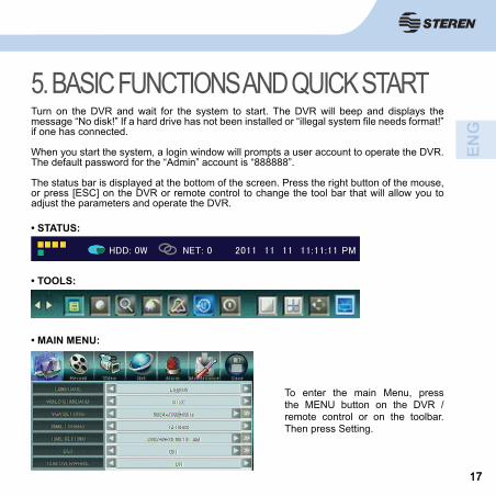
5. BASIC FUNCTIONS AND QUICK STARTTurn on the DVR and wait for the system to start. The DVR will beep and displays the message “No disk!” If a hard drive has not been installed or “illegal system fi le needs format!” if one has connected.
When you start the system, a login window will prompts a user account to operate the DVR. The default password for the “Admin” account is “888888”.
The status bar is displayed at the bottom of the screen. Press the right button of the mouse, or press [ESC] on the DVR or remote control to change the tool bar that will allow you to adjust the parameters and operate the DVR.
To enter the main Menu, press the MENU button on the DVR / remote control or on the toolbar. Then press Setting.
• STATUS:
• TOOLS:
• MAIN MENU:

1818
If you have not installed a hard drive in the CCTV-960, it will start normally, but can only be used to monitor, not to record.
After this, the system displays the view of the 4 channels live :
- Turn off:Do not turn off the DVR while you are recording.
Press the mouse right button or press [ESC] on the DVR / remote control to open the toolbar, and select the button SHUT DOWN.
Enter the user password. Once the image on the screen disappears and that the LEDs stop blinking, use the power on / off switch to turn off the DVR.
5. BASIC FUNCTIONS AND QUICK START

1919
6. SCREEN There are two display modes:
• Simultaneous view.• Single view.
You can also select a camera by pressing the keys 1 - 4 on the front panel of the DVR.
Indicates motion detection. Appears when cameras perceived movements.
(Blue): indicates that a recording is made by schedule.
(Green): indicates motion detection recording.
(Red): indicates recording activated by the alarm.
(Grey): indicates that a manual recording is made. Appears when you press REC and the DVR does not have any confi guration of recording (event, schedule, alarm).
For more information on how adjust the recording types, see section 9 “Recording”.
TIP: Can use the mouse wheel to quickly switch between individual and simultaneous view. To perform this action you must be in the simultaneous view and select a channel with double click. A time entering to view individualslide wheel change between the displays.
Channel status:

2020
7. STATE AND TOOL BAR Give a right click with the mouse or press ESC on the remote control to open the status bar.
Give two clicks or press ESC to display the bar . To the Next click or press for the third time ESC will close both Windows.
1. Indicated in red which channel of the alarm has been activated.2. Indicates that the alarm has been activated.3. Blue icon: indicates proper functioning of your hard drive.Red icon: alert of the malfunction of your hard drive.4. Icons in blue and Green: indicated that the connection to network is successful.Icons in grey: DVR disconnected from the network.5. HDD 11%: indicates the recording percentage of saved to the hard disk.HDD: OW: hard drive overwrite function turned on.6. NFT 0: number of cameras connected to the network.
• Status:

2121
1. Program: enter the main menu to perform system confi guration.
2. Manual record: start and stop recording manually. Once you select this option, must choose which cameras perform the recordings.
3. Record search for: useful for search, play and backup records in a external storage unit (USB Flash memory).
4. PTZ: opens the operation menu for PT or PTZ cameras.
5. Clear alarm: cancel alarm notifi cation. Pressing this icon displays a message along with the current state of the alarm.
6. Quick playback: in the simultaneous view, select the desired channel with the cursor and enter this option to choose the recording period that you want to display.
7. Shut down: enables shutdown safely.
8. Single channel: press this icon to select the single display.
9. Four channels: select the simultaneous view.
10. Position: using this icon can adjust the screen position.
11.- TV/Monitor: select the auxiliary video output (VGA or CVBS composite video).
12. Mute on/off: turns off the sound.
• TOOLS:
7. STATE AND TOOL BAR

2222
13. Picture Freeze: press for freeze the image. Press again to disable this function.
14. PIP 1X1: allows you to display a channel in full screen and one more on the small screen. To select the channel to display simply give click on the desired channel.
15 PIP 1X2: allows you to display a channel in full screen and two more on the small screen. To select channels to view simply give on them click.
8. USING THE HARD DISK
Before you perform any recording you need to format the hard disk:
1. Login as Admin and enter the password “888888” factory.
2. Press MENU on the remote control / DVR front panel or double right click with the mouse to enter the toolbar, and select [System].
3. Enter to [Maintenance] → [HDD MANAGE]
8.1 Format the hard disk

2323
The entire contents of the disk will be deleted when it is formatted.Reformatting your hard drive will not erase recording confi guration, users and passwords established in CCTV-960. Only videos and extras data contained in the hard disk will be deleted.
4. Click on [> >] to open hard disk management window.
5. Information on the hard disk Displays. Click [Formatting] to start the hard disk formatting.
6. Wait for the process to complete and select [Quit] to return to the main menu.
1. Remove the screws (4 on the sides, 3 in the back) from the DVR cover and carefully pull cover off.
2. Connect the fl at SATA cable to your hard drive, making sure to insert it properly by aligning the tab on the side of the cable to the opening in the DVR, otherwise you will not be able to connect it.
3. Connect the power cable to the hard drive.
4. Place the hard drive inside the DVR. Secure it in place with screws on each side.
5. Place the outer cover back on and be sure to reattach it fi rmly with the screws.
8.2 Hard drive installation
8. USING THE HARD DISK

2424
9. RECORDING Before you can start recording it is essential that you have installed and formatted the
hard disk, otherwise it will only be limited to the camera viewing.
The DVR has 2 recording methods:
9.1 Manual recordingThis recording mode is used when the DVR does not have any recording confi guration (event, time or alarm).
To stop recording, press the REC button (front panel / remote control) or uncheck the channels that perform recordings.
CH1
MENU ESC REC
CH2 CH3
BACKUP
• Option 2: press [MENU] on the remote control / front panel of the DVR or double click with the mouse and select [Manual record] on the toolbar.
The following window appears, select the channels to be recorded and press [OK] to confi rm.
• Option 1: press at any time the [REC] button on the front panel or remote control. The gray appears indicator in the active channels and the red LED will begin to Flash, noting the recording status.
Press [REC] again to stop recording.

2525
9.2 Scheduled recording1. To begin to schedule recordings go to main menu and select Rercord.2. In the VIDEO CH option, select the channel number you want to apply the preset (1, 2, 3, 4 or all)3 Select [> >] click RECORD SCHEDULE to open the time window.
- Not record: this mode is useful if you want to use the CCTV-960 only to monitor.
- Continuous record: in this option the CCTV-960 will begin recording in the confi gured day and time range.
- Motion and Alarm record: starts recording when there is an event (motion detection or alarm activation).
- Motion record: indicates that the recording will begin when there is motion detection. The sensitivity can be adjusted.
- Alarm record: starts recording when activated the alarm.
4. A grid will show on screen. Each horizontal row is a day of the week and every box is one hour.In the color boxes at the bottom, select record mode to be applied. The meaning of the colors is as follows:
9. RECORDING

2626
5. Once you have selected the type of recording, you can click on the boxes which you want to apply the settings.
6. Confi rm by selecting OK. The DVR is now programmed for recording the hours marked. In case you want to stop the recording, It must enter this menu and uncheck the appropriate boxes with the mode no. grab.
TIPS: In this menu can also use the arrow keys (for navigation) and ENTER button on the CCTV-960 or or remote control.If you press a day button you can mark all hours.
9. RECORDING

2727
10. VIDEO PLAYBACK AND BACKUP1. To start the recording playback you must enter to the Record Search menu. There are two modes:
A) Press the play / pause button on the DVR or remote control.
B) Double click with the right button of the mouse to open the toolbar and select [Record Search].
2. Use ▼, ▲buttons, to select the year, month and day that wants to explore.
3. Select the channels in which to search and select [Search]. Logs results will be displayed on the screen with different colors to indicate the recording type.
4. When there are fi les from the selected date, use to zoom in or zoom out the timeline.
- If part of the timeline you are looking for is outside the screen, use the buttons .
Record explorer window

2828
5. After the search is complete, you must choose an extract to play.
Select the start by clicking with the left mouse button on the timeline. Also check the end by clicking again. Note that the duration you selected is indicated with two pink lines. To deselect simply right double click with the mouse.
6. Press [Play] to confi rm your selection. Recording playback starts automatically.
7. Controls and the reproduction of the channels which were recordings will display. If you want to display only a channel, select it with a double click.
You can select a camera by pressing the 1 - 4 keys on the front panel of the DVR or on the remote control.
1. Press this button to rewind during playback 1 x, 8x and 16x.
2. Select this button to resume playback after having pressed pause.
• Playback controls
10. VIDEO PLAYBACK AND BACKUP

2929
3. Select this button to stop playback and return to the record explorer.
4. Press this button for high speed playback 1x, 2x, 4x, 8x, 16x, 1/8x, ¼x ½x.
5. Press this button repeatedly to display step by step.
6. Press to switch between individual and simultaneous view .
7. This tool is useful for exporting a video clip to a USB storage device. When you decide to start the cut click this button . Note that the scissors tool turns red. A time that want to fi nish the cut again, press of the icon will return to its normal color (blue).
Remember, only cut the channel selected in Explorer records will be made.
8 . Is used to export the clipping previously selected with the scissors tool. Enter this option , connect a USB storage device on the rear panel of the DVR, select the video that you want to save, and click on the [Backup] button.
The DVR will inform you when the video has been exported. Finally see the fi le on any computer.
8. To stop and exit click on the stop button.
9. If you want to export the selected video, connect a USB storage device into the DVR rear port and choose the [Backup] button.
Then choose format that the video is going to be exported (MP4, AVI, H264Roh). Finally, click on the [Backup] button.
Wait for the fi les to be saved to your USB device, a progress line will be displayed. CCTV-960 will emit an audible alert and confi rm export completion with a message.
10. VIDEO PLAYBACK AND BACKUP

3030
Remove media from the USB port and connect it to your computer.
Open external storage on your computer to search for exported fi les. Remember that the name of the video will be the same as that assigned to the DVR. Below an example and its description:
3-20120913 091500Channel - year/month/day hour/minute
If the size of the video is very large, the export may take several minutes.
10. VIDEO PLAYBACK AND BACKUP

3131
11. ALARM INSTALLATION1. Observe the following connection diagram to use CCTV-960 with an alarm:
2. In the DVR enter MENU > ALARM > ALAARM INPUT CH, and select the alarm input (1-4 or all) that you want to confi gure.
3. Select a mode of operation of alarm for the selected channel:
-N.O.: Normally open. The sensor must have a constant voltage level output low. If the output voltage changes from a low level to a high level the DVR will activate.
-N.C.: Normally closed. The sensor must have a constant level of high voltage output. The DVR will activate if the output voltage changes from a high level to a low level.

3232
ALARM OUT: enable external alarm.BUZZER: activate DVR ringer.UPLOAD: Select to send a message to the browser applet when the alarm goes off. The message is displayed in the upper right corner of the screen of the browser window. (Requires a remote connection established between the DVR and a PC via Internet).EMAIL: warning mail.UPLOAD VIA FTP: transmits images to an FTP server when an event is triggered.
6. ALARM ZOOM OUT: if active “Alarm zoom” function option handling events, this option sets the time (in seconds) to show the display.
5. Select the ALARM SETTING option and set the desired time to activate or deactivate the alarm.
Red: Activates the alarm function.
White: Deactivates the alarm function.
4. In the EVENT HANDLING option select activities that the DVR will make when the alarm is activated:
RECORD: select the channel number that starts recording when the alarm goes off.PTZ PRESET: sets the PTZ position preset for the selected channelsALARM ZOOM OUT: allows full screen viewing of the selected channels.
11. ALARM INSTALLATION

3333
7. DEVICE EXCEPTION ACTION: this option allows you to select the alarms and warnings that will activate the CCTV-960 to detect one of the following events.
- HDD Full: If the disk is full, the system will be notifi ed according to the selected warnings.-Off line: selected alarms will activate if there is a disconnection from power.-IP collision: If there is a confl ict of IP addresses within the same network, your device will activate confi gured alarms.
11. ALARM INSTALLATION

3434
Connect PT or PTZ camerasAccess the MENU > VIDEO menu to confi gure the DVR parameters (parameters should be the same as PT or PTZ camera).
1. In the CAMERA CH fi eld, select the channel of the DVR where you will connect the PT or PTZ camera.2. PTZ PROTOCOL, select the Protocol of the DVR according to your camera. Importantly, these values must be the same between the camera and the CCTV-960.3. According to your needs in PTZ BAUDRATE, select the same baudrate both in the camera and DVR, the options are: 1200, 2400, 4800, 9600.4. Select the address (PTZ ID) that has been established in the PT or PTZ camera. Choose a number from 0 to 255. Press the arrow buttons to select a value.
If you want to connect another camera simply select an address and different channel.
12. PTZ
12. PTZ

3535
Connect PT or PTZ camerasImportant information before you begin:
-Press the lock of this port with the help of a screwdriver to connect and secure the RS485 camera cables.-PT or PTZ RS485 camera cables are those that allow the communication of the DVR usually is marked purple positive (+) and negative (-) gray. For more information see the specifi ca-tions for your camera.
Use PT or PTZ cameras1. Once connected the camera, open the control menu:
(a) On the channel display screen, press the right mouse button twice to enter the toolbar and select the PTZ option.(b) Press the PTZ button on the front panel of the DVR.
1. Insert the RS485 cables from the camera in RX and TX inputs on the rear panel of the DVR according to its pole.
2. Connect the camera cable to the channel you selected in step 1 of the instructions “PT or PTZ camera settings”. If necessary use an adapter with RCA female connector to BNC male connector.
3. Insert the power adapter to the power connector on the camera to energize it.
12. PTZ

3636
2. When you see the display screen, move your mouse to operate the PTZ or PT camera.
3. In the upper fi eld select the speed with which the camera will operate. In the event that your camera has Zoom functions, adjust focus and Iris as needed.
4. To open the extended controls click with the ▼button.
-Aux: allows to control special features of the PT or PTZ camera is connected. This function will operate differently depending on the protocol used.
-Preset: useful to fi x and use default point (Preset).In this fi eld select the desired identifi cation number and use the mouse to go to the desired position, confi rm the item by clicking on ►. To use a default simply press Select button .
-Cruise: To schedule a cruise path.
Select . In the pre-adjustment fi eld select the point that you want to add and confi rm with Dir. To add more points repeat this process, note that the upper part shows scheduled cruise route. Click on save to save and exit.
12. PTZ

3737
- Track: this option allows you to make a route recording. Enter by selecting the settings button and click on Start track record to start recording. Move the mouse to control the camera, to stop the route recording enter this option again and select Stop track record and OK. To use the recording simply select the button camera, to stop the route recording enter this option again and select Stop track record and
.
Cruise and auxiliary functions may respond in different ways or stay inactive depending on the used PT or PTZ camera.
12. PTZ

3838
13. SYSTEM CONFIGURATIONAfter you install the DVR and cameras, you can perform the major adjustments with the Setting option on the toolbar; to enter this menu, there are three modes:
(a) Press the right button of the mouse on the channel display screen and select the Setting option.(b) Press the MENU button on the front panel of the DVR.(c) press the MENU button on the remote control.
SET menu is made up of 6 main menus containing adjustment submenus.
13.1 System In this menu you can confi gure main and advanced settings of the CCTV-960.
-LANGUAGE: changes the language menu on the DVR and the language for the display texts.-VIDEO STANDARD: select the video standard of the CCTV-960 (NTSC, PAL or SECAM). To USA and Mexico use NTSC. Video by default of the DVR system is “NTSC”. The change is effective after you save and exit the menu.-VGA SETTING: Switching between different resolutions from VGA output, options are 1024x768@60Hz, 1280x1024@60Hz, 1440x900@60Hz,800x600@60Hz-TIME FORMAT: changes the time between 12 and 24 hour format.-TIME FORMAT: adjusts the date and time values. In order to avoid confusion of the recorded fi les, it is best to stop the recording before you modify the time and date.-DST: in this section you can enable (Enable) or disable (Disable) the summer time. Set the start date and the date of completion according to your region.
It is recommended that you set the time and correct the DST date, because where you need to check some crucial event this it will give veracity to the video captured by the CCTV-960.
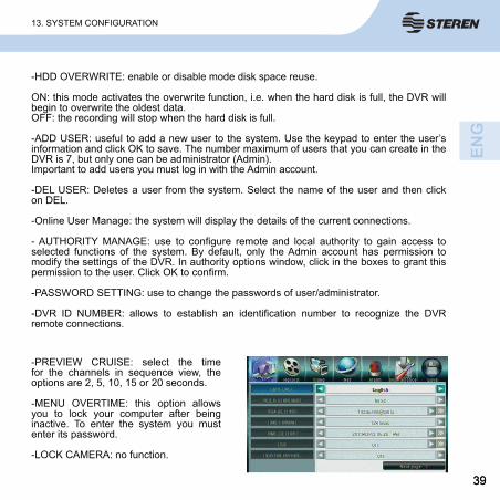
3939
-HDD OVERWRITE: enable or disable mode disk space reuse.
ON: this mode activates the overwrite function, i.e. when the hard disk is full, the DVR will begin to overwrite the oldest data.OFF: the recording will stop when the hard disk is full.
-ADD USER: useful to add a new user to the system. Use the keypad to enter the user’s information and click OK to save. The number maximum of users that you can create in the DVR is 7, but only one can be administrator (Admin).Important to add users you must log in with the Admin account.
-DEL USER: Deletes a user from the system. Select the name of the user and then click on DEL.
-Online User Manage: the system will display the details of the current connections.
- AUTHORITY MANAGE: use to confi gure remote and local authority to gain access to selected functions of the system. By default, only the Admin account has permission to modify the settings of the DVR. In authority options window, click in the boxes to grant this permission to the user. Click OK to confi rm.
-PASSWORD SETTING: use to change the passwords of user/administrator.
-DVR ID NUMBER: allows to establish an identifi cation number to recognize the DVR remote connections.
-PREVIEW CRUISE: select the time for the channels in sequence view, the options are 2, 5, 10, 15 or 20 seconds.
-MENU OVERTIME: this option allows you to lock your computer after being inactive. To enter the system you must enter its password.
-LOCK CAMERA: no function.
13. SYSTEM CONFIGURATION

4040
13.2 RecordIt contains settings regarding schedules and recording quality.
-VIDEO CH: Select the camera channel to apply relevant confi gurations. Select “All” to apply to all channels. -RECORD SCHEDULE: In this section, recording hours can be adjusted, see 9. RECORDING for more information.-RECORD QUALITY: select the quality level for recording audio / video. The options are better (768 kbps), high (640 Kbps), medium (512 kbps), low (384 kbps) or user-defi ned. -RECORD FRAME RATE: adjusts the frequency measurement at which the frames will be generated, the options are 1, 3, 7 and 15 FPS, all (30/25 fps) or user-defi ned. For the user-defi ned option, click the >> key to access the keypad. Enter the value of the quality of the recording and click OK to accept the changes.-RECORD SOURCE: select the recording mode, video and audio or video record only.-OSD SETTING: Defi ne the information that will be recorded as OSD (on screen display). The options are: brand name and time stamp of the camera, camera name, time stamp, or none. Use the arrow buttons to select an option.-RECORD RESOLUTION: selects the recording resolution, the options are: CIF(352 x 240 or 352 x 288), Half D1(704 x 240 ó 704 x 288) and D1(704 x 480 ó 704 x 576). By default the CCTV-960 has the video adjusted in CIF format.
-SUB STREAM: the DVR can transmit information to be view using the IE browser.
You can activate / deactivate (ON/OFF) secondary code or create settings customized by pressing the > > button to set the frames per second (FPS) and Bitrate (Kbit/s).
13. SYSTEM CONFIGURATION

4141
13.3 Video Click on the Video button in the system settings menu to access Camera settings and customize settings for PTZ*/standard cameras and adjust quality, motion detection and privacy zones.
CAMERA CH: Select the channel to which apply your settings. Click the arrow buttons to select channel 1, 2, 3, 4, or all.
PTZ PROTOCOL: Option that allows you to select the Protocol according to the parameters set in the camera (PT or PTZ).
Before changing PTZ protocols, select the channel (camera) in the CAMERA CH fi eld.
PTZ BAUDRATE: Allows you to choose the baud rate (1200, 2400, 4800, 9600).
PTZ ID: Select the ID of the PTZ device, make sure that adjust it according to the PTZ ca-meras ID. Choose a number from 0 to 255. Press the arrow buttons to select a value. The changes are effective after save and exit the menu.
COLOR SETTING: Adjust the color attributes (brightness, contrast, hue, and saturation) of camera for the best image viewing. Make adjustments depending on the conditions in the place where the camera is installed.
MOTION DETECTION: Set the motion detection sensitivity and manually confi gure zones for motion detection. You can scroll <>to select one of four sensitivity options.
13. SYSTEM CONFIGURATION

4242
Click on the >> button to enter more options.
-Motion detection area setting: click on the blocks with the left mouse button and drag. The blue color indicates effective detection area, transparent means disabled. Click with the right mouse button to save changes and exit.
-Motion detection plan setting: opens an additional window to confi gure the schedule on which this feature will be activated.
Press the left button of the mouse or arrow keys and ENTER in the DVR or remote control to highlight the activation type color in the hour and day boxes:
* Red: Activates the alarm function.* White: Deactivates the alarm function.
13. SYSTEM CONFIGURATION

4343
MASK: Each camera can defi ne multiple regions for privacy protection, i.e. blocks an established area in that sensor in channel view to appear on screen.
To add press and hold the left button of the mouse and select the area, to erase masks select them with the right button. Each region of privacy will be shown in blue color when performing a recording.
Masks placed only will be during the live viewing screen process and while recording, but they will not be recorded in the fi nal video.
MOTION HANDLING: This option allows to select the type of action which will be activated in the case of an event (motion detection).
-RECOR: select the cameras that you want to activate for this application.
-ALARM ZOOM OUT: allows viewing in full screen of the selected channels.
-ALARM OUT: activate external alarm.
-BUZZER: activate DVR ringer.
-UPLOAD: Select to send a message to the browser applet when motion is detected. The message is displayed in the upper right corner of the screen of the browser window. (Requires an established remote connection between the DVR and a PC via Internet).
-EMAIL: sends an email to the address confi gured.
13. SYSTEM CONFIGURATION

4444
Video lost HANDLING: this application allows you to activate a warning when there is a video loss.
-ALARM OUT: enable external alarm.-BUZZER: activate DVR ringer.-UPLOAD: Select to send a message to the applet from the browser when it detects video loss. The message is displayed in the upper right corner of the screen of the browser window. (Requires an established remote connection between the DVR and a PC via Internet).-EMAIL: sends an email to the confi gured address.
CHANNEL NAME SETTING: Click the >> button to display the channel name. Enter or change the channel name using the keypad. Click OK to save the new name.Camera Offset:
13. SYSTEM CONFIGURATION

4545
13.4 NetThe DVR supports two options for online viewing after confi guring an IP address:
-DHCP (automatic mode). Acquires the IP address using the DHCP client model.
-Static IP (manual mode). Enter the IP address using the static IP model (enter data for direct IP, subnet mask and gateway fi elds.
Note: For specifi c information of your network and an explanation of the network settings, contact your network administrator or Internet service provider.
HTTP PORT: HTTP port connects to the DVR web server. By default, the value is 87. If necessary, you can specify a different port number.
COMMAND PORT: The command port controls the DVR. By default, the value is 5050. If necessary, you can specify a different port number.
MEDIA PORT: Media port is used for transferring audio and video. By default, the value is 6050. If necessary, you can specify a different port number.
PPPOE SETTING: Use the arrow keys to activate / deactivate PPPoE setting. The changes are effective after you save.
Click on the >> button to gain access to the settings window. Use the keypad to enter the account name and the user password. You can obtain these data with your Internet service provider.
PPPOE IP: PPPoE IP values are based on your Internet account. For details, please contact your Internet service provider.
DNS ADDRESS: Place the cursor on a value and use the pop-up keypad to enter your DNS address.
13. SYSTEM CONFIGURATION

4646
DDNS: click the arrow to activate or disable the DDNS option. When enabled, click the >> button to access the DDNS settings window and adjust DDNS server, name and key. For details, please contact your Internet service provider.
Click on >> to access the email setting window. Use the keypad to enter the e-mail addresses of the people who need to receive alarm notifi cations. Enter the user name and the password for the e-mail account that will send the notifi cation emails and enter the server and port details.
AUTO REGISTER: Click on the arrow to activate or disable Auto Register option. When it is enabled, click the >> button to have access to the automatic registration settings window and adjust the IP server, port server and interval.
For details, please contact your Internet service provider.
Enter the e-mail address of the person who is going to receive the email.
13. SYSTEM CONFIGURATION

4747
To activate email notifi cations triggered by alarm, the functions must be activated in the alarm menu.
Click the view button to gain access to the list of e-mail addresses of those who will receive the email. Click on the DEL button to remove an address from the list. Click Del All to delete all email addresses from the list. Click OK to save your changes. Click Cancel to exit the window without saving.
MOBILE PORT: the DVR allows remote access from a mobile phone. Indicate the port that uses the mobile phone (default is 7050).
-UPnP: the user can select UPnP and enable UPnP function on the router in order to access the DVR through the WAN.
-FTP SETTING: transmits images to an FTP server when an event is activated (movement or sensor).
Press >> to confi gure it. Server: Enter the port IP address, Port: enter the FTP port number, User Name: Enter your user name and Password: enter the password.
See section 11. ALARM installation for more information on this menu.13.5 Alarm
13. SYSTEM CONFIGURATION

4848
-LOG VIEW: click the >> button to open the records screen. In the type fi eld select one of the following options: all, operation, emergency and alarm.
In the time search fi eld, enter the date and time to search for the record.
Click the search button to display the desired record or records. Depending on the size and quantity of records it may take several minutes to populate the list.
The fi rst column is the start time of an event in the AAAAMMDD HHMMSS format. The second column is the event description.
If multiple events do not fi t in a window, click the Prev or Next button at the bottom of the window to move between windows.
13.6 Maintenance
13. SYSTEM CONFIGURATION

4949
-UPGRADE: This option allows you to upgrade the DVR software via a USB memory.Make sure that the USB device is connected properly and has the corresponding updates. Follow the instructions on screen to begin the upgrade.Once it has completed, you must restart the device before the changes will take effect.
-HDD MANAGE: Click the >> button to see the window used to format and confi gure the DVR unit hard disk drive (HDD).
Note: Before making recordings the hard disk must be formatted using the DVR. To format the HDD, you must log on as an administrator.
To format the hard disk, click the format button. The formatting process status is displayed in the progress bar. Depending on the size of the HDD, the formatting may take a few minutes. Click Exit to stop the formatting process.
-USB Manage: displays information of the connected USB memory device. To format the device click on the format button.
-COPY SETTINGS TO USB: stores the information of the CCTV-960 settings on the storage device. Connect the storage device to the USB port on the system.
-LOAD SETTINGS FROM USB: applies the settings of the storage device information to CCTV-960. Connect the device to store data from the system to the USB port.
-AUTO MAINTAIN.
-HDD CAPACITY: this fi eld shows the total/available hard drive storage capacity.
-HARDWARE VERSION: displays the version of the DVR hardware.
-SOFTWARE VERSION: fi eld shows the current DVR software version.
-SOFTWARE RELEASE DATE: shows the date of the version of software installed.
-MAC ADDRESS: shows the MAC address of the DVR.
13. SYSTEM CONFIGURATION

5050
13.6 Save -SAVE & EXIT: click this button to save the settings and exit the menu.-EXIT: click to exit the menu without saving changes.-RESTORE DEFAULTS: useful to reset all settings to the factory defaults.-LOGOUT: click on the Logout end session button to exit the system. Please login again using another username and password to operate the DVR.
The following instructions are only for reference. Look for how to open ports and confi gure the modem with your Internet service provider (ISP).
Consult a technician in case of not knowing how to connect a DVR to the Internet.
14. NETWORK CONNECTION
MAIN OUT LAN ALARMIN
12 34 GG TX+
TX-
TX+
- +
ALARMOUT
RS4
1. Connect the DVR to a LAN port of the modem via a network cable.

5151
3. It is recommended to leave the factory settings in the HTTP port (which establishes communication with the modem), command port and media port fi elds; however, you can assign a special range.
Consult your network administrator for more information.
These same ports must be open on the modem to monitor the DVR locally and remotely.
- DHCP: with this option, the modem automatically assigns the address and ranges in the IP address, subnet mask and gateway fi elds.
- IP (static): when you use this option, both the IP address, subnet mask, and the gateway must be assigned manually. Remember, these parameters must be within the modem range.
2. Select a mode to assign the IP address to the DVR. Enter to MENU > network and choose from these options:
11. NETWORK CONNECTION

5252
4. To monitor it locally (LAN), enter the IP address you assigned to the DVR in the Internet Explorer window.
Consult your Internet service provider for the public IP.
5. Enable ActiveX components on your computer (if they are not enabled, you cannot monitor the DVR). Follow this setting path:
Internet Options > Security > Internet > custom level > enable Active X controls
6. Once the DVR home screen appears, enter your default username (Admin) and password (888888). Press “Login” to enter.
-To monitor remote (WAN) mode, enter the public IP.
Note: if you have selected in the HTTP port fi eld a different range than 80, enter the public IP address followed by a colon and the port number that you assigned, for example: http://189.254.6.194:87/
11. NETWORK CONNECTION

5353
Once you enter them, you will see a remote and local operation window that operates in same way as the DVR menus.
In case you do not see the camera image, double click on every cannel to see them.
11. NETWORK CONNECTION

5454
16. SPECIFICATIONS
Product design and specifi cations are subject to change, without notice.
Input: 12 V - - - 5A
Remote ControlInput: 3 V - - - (2 x AAA)
AC Power AdapterInput: 100-240 V~ 50/60Hz 1.5AOutput: 12 V - - - 5A
Nominal consumption: 11.52 kWh/monthStand-by power consumption: 15.7 kWh/year
15.TROUBLESHOOTINGTROUBLE SOLUTION
CCTV-960 does not turns on after connecting
it to the mains.
-It is possible that the power adapter is faulty. In this case consult a dealer for replacement.-There are probably hardware problems. In this case consult a dealer.
I can’t record
-It has not formatted the hard disk. The hard disk must be formatted manually the fi rst time.-The recording function is not active or the confi guration is incorrect. See paragraph 9.-The hard drive is full and does not activate the overwri-te function. Reference is made in paragraph 13.1 system (HDD overwrite).-The hard drive is damaged.
Mouse is not detected by the CCTV-960.
-Disconnect and plug the mouse into the USB port marked as MOUSE.

5555
WARRANTY
This Steren product is warranted under normal usage against defects in workmanship and materials to the original purchaser for one year from the date of purchase.
CONDITIONS
1. This warranty card with all the required information, invoice, product box or package, and product, must be presented when warranty service is required.2. If the product is in the warranty time, the company will repair it free of charge.3. The repairing time will not exceed 30 natural days, from the day the claim was received.4. Steren sell parts, components, consumables and accessories to customer, as well as warranty service, at any of the addresses mentioned later.
THIS WARRANTY IS VOID IN THE NEXT CASES:
If the product has been damaged by an accident, acts of God, mishandling, leaky batteries, failure to follow enclosed instructions, improper repair by unauthorized personnel, improper safe keeping, among others.
a) The consumer can also claim the warranty service in the purchase establishment.b) If you lose the warranty card, we can reissue it, if you show the invoice or purchase ticket.
RETAILER INFORMATIONName of the retailerAddressProductBrandPart numberSerial numberDate of delivery
Product: Ethernet digital video recorder systemPart number: CCTV-960Brand: Steren
In case your product fails or have questions, please
contact your nearest dealer. If you are in Mexico, please
call to our Call Center.
01 800 500 9000
