cd horizon agile - mt ortho srl
TRANSCRIPT

CD HORIZON® AGILE™
Dynamic Stabilization Device Surgical TechniqueAs described by:
Kevin T. Foley, MDDepartment of NeurosurgeryUniversity of TennesseeMemphis, Tennessee
Robert S. Bray Jr., MDSaint John’s Health CenterSanta Monica, California
Jean-Charles Le Huec, MD, PhDSpine Unit, Pellegrin HospitalBordeaux, France
David P. Rouben, MDRiver City Orthopaedic SurgeonsLouisville, Kentucky


�CD HORIZON® AGILE™ Dynamic Stabilization Device
MEDTRONIC
Table of Contents
Innovative and Validated Technology
Product Overview . . . . . . . . . . . . . . . . . . . . . . . . . . . . . . . . . . . . . . . . . . . . . . . . . . . . . . . . . . . 2
Design Features . . . . . . . . . . . . . . . . . . . . . . . . . . . . . . . . . . . . . . . . . . . . . . . . . . . . . . . . . . . . . 3
Instrument Set. . . . . . . . . . . . . . . . . . . . . . . . . . . . . . . . . . . . . . . . . . . . . . . . . . . . . . . . . . . . . . 4
Single Level Technique
Surgical Considerations . . . . . . . . . . . . . . . . . . . . . . . . . . . . . . . . . . . . . . . . . . . . . . . . . . . . . . 5
Approach and Screw Preparation . . . . . . . . . . . . . . . . . . . . . . . . . . . . . . . . . . . . . . . . . . . . . 6
Screw Placement . . . . . . . . . . . . . . . . . . . . . . . . . . . . . . . . . . . . . . . . . . . . . . . . . . . . . . . . . . . . 7
Trialing . . . . . . . . . . . . . . . . . . . . . . . . . . . . . . . . . . . . . . . . . . . . . . . . . . . . . . . . . . . . . . . . . . . . . 9
Rod Selection and Insertion . . . . . . . . . . . . . . . . . . . . . . . . . . . . . . . . . . . . . . . . . . . . . . . . . 10
Provisional Tightening . . . . . . . . . . . . . . . . . . . . . . . . . . . . . . . . . . . . . . . . . . . . . . . . . . . . . . . 11
Disc Neutralization/Distraction . . . . . . . . . . . . . . . . . . . . . . . . . . . . . . . . . . . . . . . . . . . . . . .12
Final Tightening . . . . . . . . . . . . . . . . . . . . . . . . . . . . . . . . . . . . . . . . . . . . . . . . . . . . . . . . . . . . .13
Final Construct. . . . . . . . . . . . . . . . . . . . . . . . . . . . . . . . . . . . . . . . . . . . . . . . . . . . . . . . . . . . . .14
Implant Explantation . . . . . . . . . . . . . . . . . . . . . . . . . . . . . . . . . . . . . . . . . . . . . . . . . . . . . . . .14
Adjacent Level Technique
Adjacent Level Device Features . . . . . . . . . . . . . . . . . . . . . . . . . . . . . . . . . . . . . . . . . . . . . . .15
Discectomy and Endplate Preparation . . . . . . . . . . . . . . . . . . . . . . . . . . . . . . . . . . . . . . . . .16
Screw Placement . . . . . . . . . . . . . . . . . . . . . . . . . . . . . . . . . . . . . . . . . . . . . . . . . . . . . . . . . . . .16
Interbody Spacer Placement . . . . . . . . . . . . . . . . . . . . . . . . . . . . . . . . . . . . . . . . . . . . . . . . .17
Rod Measurement Tool . . . . . . . . . . . . . . . . . . . . . . . . . . . . . . . . . . . . . . . . . . . . . . . . . . . . . .18
Rod Contouring and Cutting . . . . . . . . . . . . . . . . . . . . . . . . . . . . . . . . . . . . . . . . . . . . . . . . . .19
Final Construct. . . . . . . . . . . . . . . . . . . . . . . . . . . . . . . . . . . . . . . . . . . . . . . . . . . . . . . . . . . . . .19
Product Ordering Information . . . . . . . . . . . . . . . . . . . . . . . . . . . . . . . . . . . . . . . . . . . . . . . . 20
Important Product Information . . . . . . . . . . . . . . . . . . . . . . . . . . . . . . . . . . . . . . . . . . . . . . 21

� CD HORIZON® AGILE™ Dynamic Stabilization Device
MEDTRONIC
The CD HORIZON® AGILE™ Dynamic
Stabilization Device is an innovative posterior
stabilization implant that is designed to treat
symptoms of degenerative conditions of the
lumbar spine. The CD HORIZON® AGILE™
Dynamic Stabilization Device can be used to
treat single-level pathology or to provide a less
rigid transitional zone above or below rigidly
fused spinal segments.
The MAST QUADRANT™ Retractor Set, in
combination with the CD HORIZON® AGILE™
Dynamic Stabilization Device and CD HORIZON®
LEGACY™ System Pedicle Screws, allows
access, fusion and fixation in one minimally
invasive approach. It provides the surgeon
with more versatility and reproducibility to
perform less invasive dynamic stabilization
surgery with confidence.
Innovative and Validated Technology
CD HORIZON® LEGACY™ Spinal System
Multi Axial Screw
MAST QUADRANT™ Retractor Set
CD HORIZON® AGILE™ Dynamic Stabilization Device

�CD HORIZON® AGILE™ Dynamic Stabilization Device
MEDTRONIC
Innovative and Validated Technology
Design Features
Without Compressive Load With Compressive Load
High Strength Crimp
Polycarbonate Urethane Spacer
CP Titanium Distal Rod
Load Bearing Flanges
Predetermined stiffness options are available to match individual patient anatomy and clinical needs. The stiffness of the rods correlates to the spacer size (e.g., increasing stiffness with the shorter spacer). The 15mm spacer size allows the most axial compression, while the 10mm spacer offers a slightly stiffer option.
Floating Titanium Alloy Cable
15mm Spacer Option
10mm Spacer Option
When combined with CD HORIZON® LEGACY™ System pedicle screws and a minimally invasive surgical approach, such as the MAST QUADRANT™ Retractor Set, the CD HORIZON® AGILE™ Device dynamically stabilizes the affected segment while allowing a streamlined surgical technique designed to preserve the natural anatomy.
The CD HORIZON® AGILE™ Device floating cable design allows for an axial compressive load while retaining a constant stiffness without buckling the cable. This provides better fatigue properties and axial compressive capability of the spacer.
CP Titanium Proximal Rod
Free Moving Cable End
Extended Cable
Compressed Spacer
� CD HORIZON® AGILE™ Dynamic Stabilization Device
MEDTRONIC
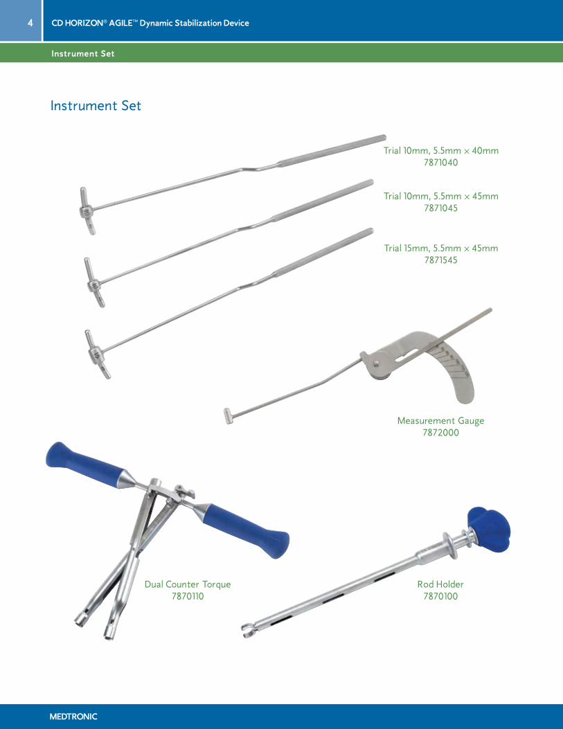
Instrument Set
Dual Counter Torque 7870110
Measurement Gauge 7872000
Trial 10mm, 5.5mm ∞ 40mm 7871040
Trial 15mm, 5.5mm ∞ 45mm 7871545
Trial 10mm, 5.5mm ∞ 45mm 7871045
Instrument Set
Rod Holder 7870100
�CD HORIZON® AGILE™ Dynamic Stabilization Device
MEDTRONIC
Single Level Technique
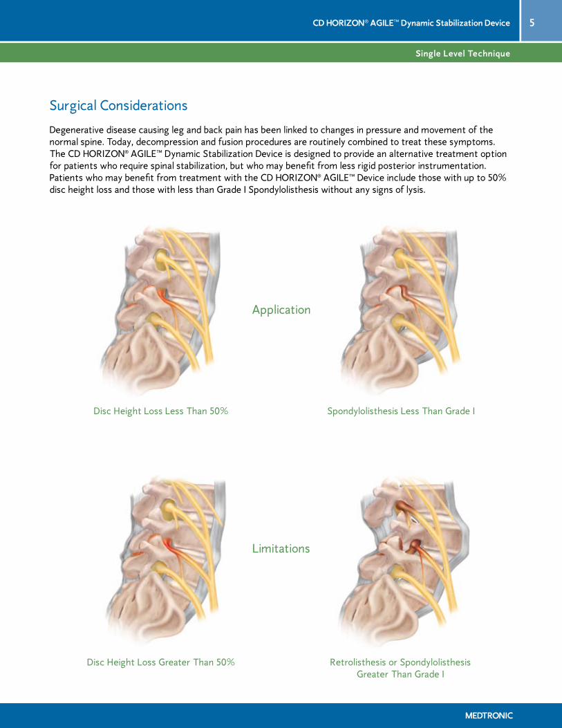
Surgical Considerations
Degenerative disease causing leg and back pain has been linked to changes in pressure and movement of the normal spine. Today, decompression and fusion procedures are routinely combined to treat these symptoms. The CD HORIZON® AGILE™ Dynamic Stabilization Device is designed to provide an alternative treatment option for patients who require spinal stabilization, but who may benefit from less rigid posterior instrumentation. Patients who may benefit from treatment with the CD HORIZON® AGILE™ Device include those with up to 50% disc height loss and those with less than Grade I Spondylolisthesis without any signs of lysis.
Disc Height Loss Greater Than 50% Retrolisthesis or Spondylolisthesis Greater Than Grade I
Disc Height Loss Less Than 50% Spondylolisthesis Less Than Grade I
Limitations
Application

� CD HORIZON® AGILE™ Dynamic Stabilization Device
MEDTRONIC
Single Level Technique
Approach and Screw Preparation
The CD HORIZON® AGILE™ Dynamic Stabilization Device may be implanted through either an open or MAST™ approach. For illustrative purposes, this technique will demonstrate an open approach. For information on the MAST™ approach utilizing the MAST QUADRANT™ Retractor Set, please refer to the MAST QUADRANT™ Retractor Set Surgical Technique.
During pedicle preparation, consider the pedicle as roughly a cylindrical structure. As the pedicle is traversed, the trajectory should allow the needle or screw to remain lateral to the medial pedicle wall. Screws should be slightly proud to allow placement of the spacer lateral to the facets. When choosing a screw length consider a longer length to allow adequate bone-to-screw purchase (Figure 1).
Figure 1

�CD HORIZON® AGILE™ Dynamic Stabilization Device
MEDTRONIC
Single Level Technique
Screw Placement
With the pedicles prepared and the proper screw lengths determined, fully insert the hex end of the Multi Axial Screwdriver into the screw head (Figure 2). Next, thread the screwdriver sleeve into the screw head (Figure 3). The combination of the hex head and the threaded sleeve provide a stable insertion instrument for inserting the Multi Axial Screws bilaterally.
Intraoperative A/P and lateral imaging should be taken to evaluate the position of the screws in two planes. When fully inserted, the screws should be oriented toward the superior endplate where the bone density is higher and extend 50% to 80% into the vertebral body. In order to provide space for the desired spacer length, it is recommended that the screws be placed parallel to the superior endplate. At L5 – S1, it is helpful to place the S1 screw in a caudal to cephalad orientation (low to high) across the S1 pedicle, especially if a 15mm CD HORIZON® AGILE™ Device is desired.
Although the Multi Axial Screws are able to accommodate moderate asymmetry in screw alignment, it is helpful to adjust the height of the screw heads so that when an imaginary line is drawn on top of the screw heads it will form a gentle lordotic curve (Figure 4). This will facilitate subsequent rod placement. Once the screw is inserted, the instrument sleeve is unscrewed and the screwdriver is disengaged from the screw.
Figure 4
Figure 2 Figure 3

Section Head Here
� CD HORIZON® AGILE™ Dynamic Stabilization Device
MEDTRONIC
Single Level Technique
Screw Placement (continued)
The bone screws should be parallel to the superior endplates. Incorrect screw placement minimizes the interpedicular area between the screw heads and could prevent the device from being placed (Figure 5).
In cases where screw heads are convergent due to greater posterior disc height loss (Figure 6), slight distraction through patient positioning or gentle intraoperative distraction may be used. In order to maintain good sagittal balance, care should be taken not to over-distract. Please refer to the section on distraction for additional information.
Figure 5 Figure 6

Section Head Here
�CD HORIZON® AGILE™ Dynamic Stabilization Device
MEDTRONIC
Single Level Technique
Trialing
The bayonetted Trials are used to determine the appropriate size rod implant. The Trials are marked by the spacer size and overall rod length (Figure 7). Sequentially position the Trials in the implant heads until the desired implant is determined. Screws should not be advanced too far into the bone where the spacer will collide with the facet (Figures 8a and 8b). The correct Trial should extend outside the screw heads on both ends and allow adequate room for the spacer. The Trials can also be used to determine if the screws should be advanced deeper into the vertebral body.
Figures 8a and 8b
Correct Incorrect
End-to-End Implant Length
Spacer SizeFigure 7

�0 CD HORIZON® AGILE™ Dynamic Stabilization Device
MEDTRONIC
Single Level Technique
Rod Selection and Insertion
When choosing a rod size, ensure the rod is long enough for adequate fixation to be performed. NOTE: Ensure that the Set Screw does not engage the rod past the Set Screw line (Figure 9).
To place the CD HORIZON® AGILE™ Implant into the Rod Holder, place the blue handle against the palm and squeeze the lip of the outer shaft with the index and middle fingers (Figure 10). This will move the outer shaft over the inner shaft and open the claws to hold the PCU spacer portion of the rod. Make sure the PCU spacer is securely positioned in the claws before placing the rod in the screw heads (Figure 11).
When placing the rod, make sure that the lordotic marker is visible. To ensure proper alignment, do not release the rod from the Rod Holder until after provisional tightening is performed. Due to the lordotic curve in the rod, the rod must be correctly positioned to seat securely in the screw heads. Allow enough distance between the screw heads and the spacer to subsequently seat the dual counter torque on both screw heads.
Figure 10
Figure 11
Figure 9
Set Screw Line

��CD HORIZON® AGILE™ Dynamic Stabilization Device
MEDTRONIC
Single Level Technique
Provisional Tightening
The laser etched lordotic marker running the length of the rod should be positioned upward with both screw heads aligned (Figure 12). This will help ensure proper engagement of the Dual Counter Torque.
Once the rod is correctly seated in the bottom of the screw heads, insert the Break-Off Set Screws (hereafter referred to as “Set Screws”) using the Set Screw Starter. Multiple Set Screws can be loaded into the Set Screw Starter for intraoperative efficiency. To ensure proper alignment, maintain positioning of the rod with the Rod Holder while placing the Set Screws (Figure 13). The Set Screws for both the cephalad and caudal screw heads should be placed prior to the next step.
Figure 13Figure 12

Section Head Here
�� CD HORIZON® AGILE™ Dynamic Stabilization Device
MEDTRONIC
Single Level Technique
Disc Neutralization/Distraction
The key step to disc neutralization is patient positioning in order to maintain the neutral alignment of the disc. If additional space is required above and beyond what is achieved through patient positioning, the Dual Counter Torque may be used with care.
Insert the Dual Counter Torque over the cephalad and caudal screw heads (Figure 14). Ensure that the feet of both sleeves are completely seated against the implant body and not against the Set Screw (Figures 15a and 15b). Failure to do this may result in slippage of the implant or premature breaking of the Set Screw. The Provisional Driver may be used to temporarily lock and secure the Rod and implant construct. Usually, temporary fixation of the implant may be performed numerous times without damage to either the Set Screw or the implant threads. However, if the Set Screw has been cross-threaded, it must be replaced.
Placement of the Dual Counter Torque should be done while being careful not to distract past parallel endplates. Engage the thumb lock to maintain positioning of the sleeves. The Dual Counter Torque will maintain the neutral position during Set Screw provisional tightening.
CAUTION: The Counter Torque instrument is designed specifically for use with precontoured rods and cannot be used with straight rods.
Thumb Lock
IncorrectCorrect
Figure 14
Figures 15a and 15b

IncorrectCorrect
��CD HORIZON® AGILE™ Dynamic Stabilization Device
MEDTRONIC
Single Level Technique
Final Tightening
When all implants are securely in place, final tightening and breakoff of the Set Screws is done. Care should be taken to ensure the Dual Counter Torque Sleeves are fully seated on the screw heads. Insert the Self-Retaining Break-Off Driver into one of the Dual Counter Torque sleeves which should be positioned over the implants and rod. The T-handle on the driver provides adequate leverage for the breakoff of the Set Screw (Figure 16). One handle of the Dual Counter Torque device should be held firmly to prevent torquing of the construct while the Set Screw is secured and sheared off. Repeat this process for the remaining Set Screw.
CAUTION: The Dual Counter Torque should be used instead of a standard counter torque, to prevent the CD HORIZON® AGILE™ Device from bending when breaking off the set screws (Figures 17a and 17b).
When utilizing any dynamic device, it is important to control both screw heads to maintain proper alignment of the implant. Failure to do so may result in undesirable biomechanical and fatigue properties.
Figure 16 Figures 17a and 17b

�� CD HORIZON® AGILE™ Dynamic Stabilization Device
MEDTRONIC
Single Level Technique
Final Construct
The final construct (Figures 18a and 18b) should be verified by lateral and A/P x-ray or fluoroscopy prior to closing.
Implant Explantation
For best results, the same type of MEDTRONIC instruments used for implantation should also be used for implant removal purposes. Various screwdriver sizes are available to adapt to the removal drive sizes in auto break fixation screws.
It should be noted that where excessive bone or fibrous growth has occurred from previous surgery, there may be added stress on the removal instruments and implants. Both instruments and implants may be prone to possible breakage. In this case, it is necessary to first remove the bone and/or tissue from around the implants.
Figure 18a Figure 18b

��CD HORIZON® AGILE™ Dynamic Stabilization Device
MEDTRONIC
Adjacent Level Technique
Adjacent Level Device Features
• Available with 10mm or 15mm Spacer option
• Available in lengths from 60mm to 120mm in 10mm increments
• Device can be cut and contoured to fit varying patient anatomy past the crimp line
High Strength Crimp Load Bearing Flanges
Polycarbonate Urethane Spacer
CP Titanium Proximal Rod
CP Titanium Distal Rod
Free Moving Cable End
Floating Titanium Alloy Cable
15mm Spacer Option
10mm Spacer Option

�� CD HORIZON® AGILE™ Dynamic Stabilization Device
MEDTRONIC
Adjacent Level Technique
Discectomy and Endplate Preparation
When performing an adjacent-level procedure, a conventional discectomy is performed unilaterally or bilaterally as indicated (Figure 19). Soft fragments from the intradiscal space or extruded fragments are removed in a conventional fashion. The main goal of this step is to remove extruded fragments, decompress neural elements and provide entry to the disc space for distraction with minimal or no nerve root retraction. Thorough endplate preparation should be accomplished prior to insertion of the interbody construct. The disc space is sequentially distracted until original disc space height is obtained and normal foraminal opening is restored.
Screw Placement
When placing screws at multiple levels, attention should be paid to alignment of screws. This will help avoid the need to rotate or bend the rod in order to seat it correctly in all screw heads (Figure 20).
Figure 19 Figure 20

��CD HORIZON® AGILE™ Dynamic Stabilization Device
MEDTRONIC
Adjacent Level Technique
Interbody Spacer Placement
Insert the structural graft into the disc space taking care to ensure that the construct is aligned properly. Gently impact the construct until it is 3mm to 4mm anterior to the posterior margin of the annulus (Figure 21).
Figure 21

Section Head Here
�� CD HORIZON® AGILE™ Dynamic Stabilization Device
MEDTRONIC
Adjacent Level Technique
Rod Measurement Tool
When performing an adjacent-level procedure, the Rod Measurement Tool may be attached to a Trial to select the implant size. To connect the instruments, slide the Trial into the side opening of the Rod Measurement Tool (Figure 22). When the instruments are correctly attached, the working end of the Measurement Tool will fit against the end of the Trial (Figure 23). Tighten the knurled knob on the Measurement Tool to secure the instruments together. Position the instrument assembly in the screw heads and select the implant size based on the measurement scale on the tool (Figure 24).
Figure 22
Figure 23 Figure 24

Section Head Here
��CD HORIZON® AGILE™ Dynamic Stabilization Device
MEDTRONIC
Adjacent Level Technique
Rod Contouring and Cutting
Adjacent-level implants have two etched lines on the longer end (Figure 25). The implant can be cut and contoured at any point past these lines without compromising its dynamic capabilities.
Figure 25
Lordotic Line
Set Screw Break Off Line
Crimp Line
Figures 26a and 26b
Final Construct
The final construct (Figures 26a and 26b) should be verified by lateral and A/P x-ray or fluoroscopy prior to closing.

�0 CD HORIZON® AGILE™ Dynamic Stabilization Device
MEDTRONIC
Product Ordering Information
Single Level Implants, 5.5mm Rod
Item Number Description
7881040 10mm Spacer, 5.5mm ∞ 40mm
7881045 10mm Spacer, 5.5mm ∞ 45mm
7881545 15mm Spacer, 5.5mm ∞ 45mm
Adjacent Level Implants, 5.5mm Rod
Item Number Description
7881060 10mm Spacer, 5.5mm ∞ 60mm
7881070 10mm Spacer, 5.5mm ∞ 70mm
7881080 10mm Spacer, 5.5mm ∞ 80mm
7881090 10mm Spacer, 5.5mm ∞ 90mm
7881000 10mm Spacer, 5.5mm ∞ 100mm
7881010 10mm Spacer, 5.5mm ∞ 110mm
7881020 10mm Spacer, 5.5mm ∞ 120mm
7881560 15mm Spacer, 5.5mm ∞ 60mm
7881570 15mm Spacer, 5.5mm ∞ 70mm
7881580 15mm Spacer, 5.5mm ∞ 80mm
7881590 15mm Spacer, 5.5mm ∞ 90mm
7881500 15mm Spacer, 5.5mm ∞ 100mm
7881510 15mm Spacer, 5.5mm ∞ 110mm
7881520 15mm Spacer, 5.5mm ∞ 120mm
Instrument Set
Item Number Description
7870100 Rod Holder
7870110 Dual Counter Torque
7870130 Outer Case
7870131 Outer Lid
7870132 Instrument Tray
7871040 Trial 10mm, 5.5mm ∞ 40mm
7871045 Trial 10mm, 5.5mm ∞ 45mm
7871545 Trial 15mm, 5.5mm ∞ 45mm
7872000 Measurement Gauge

��CD HORIZON® AGILE™ Dynamic Stabilization Device
MEDTRONIC
IMPORTANT INFORMATION ON THE CD HORIZON® AGILE™ Dynamic Stabilization Device
PURPOSE: The CD HORIZON® AGILE™ Dynamic Stabilization Device is intended to help provide stabilization of spinal segments of the thoracic, lumbar, and/or sacral spine.
DESCRIPTION: The CD HORIZON® AGILE™ Dynamic Stabilization Device consists of Ø5.5mm rod ends, a cable and a spacer that come assembled in a variety of shapes, sizes and rod length configurations. The device is used in a symmetric, bilateral arrangement with CD HORIZON® Spinal System pedicle screws placed lateral to the facet joints with two screws in the cephalad position and two screws in the caudal position. Certain configurations also permit fixation across two or more spinal segments.
The CD HORIZON® AGILE™ Dynamic Stabilization Device components are fabricated from medical grade titanium, titanium alloy and polycarbonate-urethane.
Never use stainless steel and titanium implant components in the same construct.
Medical grade titanium, titanium alloy and/or medical grade cobalt-chromium-molybdenum alloy may be used together. Never use titanium, titanium alloy and/or medical grade cobalt-chromium-molybdenum alloy with stainless steel in the same construct.
To achieve best results, do not use any of the CD HORIZON® Spinal System implant components with components from any other system or manufacturer unless specifically allowed to do so in this or another Medtronic Sofamor Danek document. As with all orthopaedic and neurosurgical implants, none of the CD HORIZON® Spinal System components should ever be reused under any circumstances.
Implied warranties of merchantability and fitness for a particular purpose or use are specifically excluded. See the MSD Catalog or price list for further information about warranties and limitations of liability.
CD HORIZON® AGILE™ Rods are not to be used with CROSSLINK® Plates.
INDICATIONS: When used in conjunction with CD HORIZON® Spinal System pedicle screws as a fixation system in skeletally mature patients, the CD HORIZON® AGILE™ Dynamic Stabilization Device is intended for posterior, non-cervical stabilization with or without bone graft for the following indications: degenerative disc disease (defined as back pain of discogenic or facet origin with degeneration of the disc or facet confirmed by history and radiographic studies); spondylolisthesis; trauma (i.e., fracture or dislocation); spinal stenosis; curvatures (i.e., scoliosis, kyphosis and/or lordosis); tumor; pseudarthrosis; and/or failed previous fusion.
CONTRAINDICATIONS: Contraindications include, but are not limited to:
1. Active infectious process or significant risk of infection (immunocompromise).
2. Signs of local inflammation.
3. Fever or leukocytosis.
4. Morbid obesity.
5. Pregnancy.
6. Mental illness.
7. Grossly distorted anatomy caused by congenital abnormalities.
8. Any other medical or surgical condition which would preclude the potential benefit of spinal implant surgery, such as the presence of congenital abnormalities, elevation of sedimentation rate unexplained by other diseases, elevation of white blood count (WBC), or a marked left shift in the WBC differential count.
9. Suspected or documented metal allergy or intolerance.
10. Any case where the implant components selected for use would be too large or too small to achieve a successful result.
11. Any patient having inadequate tissue coverage over the operative site or inadequate bone stock or quality.
12. Any patient in which implant utilization would interfere with anatomical structures or expected physiological performance.
13. Any patient unwilling to follow postoperative instructions.
14. Any case not described in the indications.
NOTA BENE: Although not absolute contraindications, conditions to be considered as potential factors for not using this device include:
1. Severe bone resorption.
2. Osteomalacia.
3. Severe osteoporosis.
POTENTIAL ADVERSE EVENTS: All of the possible adverse events associated with spinal surgery without instrumentation are possible. With instrumentation, a listing of potential adverse events includes, but is not limited to:
1. Early or late loosening of any or all of the components.
2. Disassembly, bending, and/or breakage of any or all of the components.
3. Foreign body (allergic) reaction to implants, debris, corrosion products (from crevice, fretting, and/or general corrosion), including metallosis, staining, tumor formation, and/or autoimmune disease.
4. Pressure on the skin from component parts in patients with inadequate tissue coverage over the implant possibly causing skin penetration, irritation, fibrosis, neurosis, and/or pain. Bursitis. Tissue or nerve damage caused by improper positioning and placement of implants or instruments.
5. Post-operative change in spinal curvature, loss of correction, height, and/or reduction.
6. Infection.
7. Dural tears, pseudomeningocele, fistula, persistent CSF leakage, meningitis.
8. Loss of neurological function (e.g., sensory and/or motor), including paralysis (complete or incomplete), dysesthesias, hyperesthesia, anesthesia, paresthesia, appearance of radiculopathy, and/or the development or continuation of pain, numbness, neuroma, spasms, sensory loss, tingling sensation, and/or visual deficits.
9. Cauda equina syndrome, neuropathy, neurological deficits (transient or permanent), paraplegia, paraparesis, reflex deficits, irritation, arachnoiditis, and/or muscle loss.
10. Urinary retention or loss of bladder control or other types of urological system compromise.
11. Scar formation possibly causing neurological compromise or compression around nerves and/or pain.
12. Fracture, microfracture, resorption, damage, or penetration of any spinal bone (including the sacrum, pedicles, and/or vertebral body) and/or bone graft or bone graft harvest site at, above, and/or below the level of surgery. Retropulsed graft.
13. Herniated nucleus pulposus, disc disruption or degeneration at, above, or below the level of surgery.
14. Non-union (or pseudarthrosis). Delayed union. Mal-union.
15. Cessation of any potential growth of the operated portion of the spine.
16. Loss of or increase in spinal mobility or function.
17. Inability to perform the activities of daily living.
18. Bone loss or decrease in bone density, possibly caused by stresses shielding.
19. Graft donor site complications including pain, fracture, or wound healing problems.
20. Ileus, gastritis, bowel obstruction or loss of bowel control or other types of gastrointestinal system compromise.
21. Hemorrhage, hematoma, occlusion, seroma, edema, hypertension, embolism, stroke, excessive bleeding, phlebitis, wound necrosis, wound dehiscence, damage to blood vessels, or other types of cardiovascular system compromise.
22. Reproductive system compromise, including sterility, loss of consortium, and sexual dysfunction.
23. Development of respiratory problems, e.g., pulmonary embolism, atelectasis, bronchitis, pneumonia, etc.
24. Change in mental status.
25. Death.
Note: Additional surgery may be necessary to correct some of these potential adverse events.
WARNINGS: The safety and effectiveness of pedicle screw spinal systems have been established only for spinal conditions with significant mechanical instability or deformity requiring fusion with instrumentation. These conditions are significant mechanical instability or deformity of the thoracic, lumbar, and sacral spine secondary to degenerative spondylolisthesis with objective evidence of neurologic impairment, fracture, dislocation, scoliosis, kyphosis, spinal tumor, and failed previous fusion (pseudarthrosis). The safety and effectiveness of this device for any other conditions are unknown.
In the absence of fusion, the instrumentation and/or one or more of its components may be expected to pull out, bend or fracture as a result of exposure to every day mechanical stresses.
PRECAUTIONS: The implantation of pedicle screw spinal systems should be performed only by experienced spinal surgeons with specific training in the use of this pedicle screw spinal system because this is a technically demanding procedure presenting a risk of serious injury to the patient.
A successful result is not always achieved in every surgical case. This fact is especially true in spinal surgery where many extenuating circumstances may compromise the results. This device system is not intended to be the sole means of spinal support. Use of this product without a bone graft or in cases that develop into a non-union will not be successful. No spinal implant can withstand body loads without the support of bone. In this event, bending, loosening, disassembly and/or breakage of the device(s) will eventually occur.
Preoperative and operating procedures, including knowledge of surgical techniques, good reduction, and proper selection and placement of the implants are important

�� CD HORIZON® AGILE™ Dynamic Stabilization Device
MEDTRONIC
IMPORTANT INFORMATION ON THE CD HORIZON® AGILE™ Dynamic Stabilization Device (Continued)
considerations in the successful utilization of the system by the surgeon. Further, the proper selection and compliance of the patient will greatly affect the results. Patients who smoke have been shown to have an increased incidence of non-unions. These patients should be advised of this fact and warned of this consequence. Obese, malnourished, and/or alcohol abuse patients are also poor candidates for spine fusion. Patients with poor muscle and bone quality and/or nerve paralysis are also poor candidates for spine fusion.
PHYSICIAN NOTE: Although the physician is the learned intermediary between the company and the patient, the important medical information given in this document should be conveyed to the patient.
!USA For US Audiences Only
CAUTION: FEDERAL LAW (USA) RESTRICTS THESE DEVICES TO SALE BY OR ON THE ORDER OF A PHYSICIAN.
Other preoperative, intraoperative, and postoperative warnings and precautions are as follows:
Implant Selection: The selection of the proper size, shape and design of the implant for each patient is crucial to the success of the procedure. Metallic surgical implants are subject to repeated stresses in use, and their strength is limited by the need to adapt the design to the size and shape of human bones. Unless great care is taken in patient selection, proper placement of the implant, and postoperative management to minimize stresses on the implant, such stresses may cause metal fatigue and consequent breakage, bending or loosening of the device before the healing process is complete, which may result in further injury or the need to remove the device prematurely.
Device Fixation: In cases where a percutaneous posterior approach is used refer to the CD HORIZON® SEXTANT® surgical technique.
For self breaking plugs, always hold the assembly with the Counter Torque device. Tighten and break-off the head of the plug to leave the assembly at optimum fixation security. After the upper part of the self breaking plug has been sheared off, further re-tightening is not necessary and not recommended. The head part should not remain in the patient. AFTER THE UPPER PART OF THE SELF BREAKING PLUG HAS BEEN SHEARED OFF, RE-ADJUSTMENT IS NOT POSSIBLE UNLESS THE PLUG IS REMOVED AND REPLACED WITH A NEW ONE.
CD HORIZON® AGILE™ RODS ARE NOT TO BE USED WITH CROSSLINK® PLATES.
PREOPERATIVE:
1. Only patients that meet the criteria described in the indications should be selected.
2. Patient conditions and/or pre dispositions such as those addressed in the aforementioned contraindications should be avoided.
3. Care should be used in the handling and storage of the implant components. The implants should not be scratched or otherwise damaged. Implants and instruments should be protected during storage, especially from corrosive environments.
4. An adequate inventory of implants should be available at the time of surgery, normally a quantity in excess of what is expected to be used.
5. Since mechanical parts are involved, the surgeon should be familiar with the various components before using the equipment and should personally assemble the devices to verify that all parts and necessary instruments are present before the surgery begins. The CD HORIZON® Spinal System components (described in the DESCRIPTION section) are not to be combined with the components from another manufacturer.
INTRAOPERATIVE:
1. Extreme caution should be used around the spinal cord and nerve roots. Damage to the nerves will cause loss of neurological functions.
2. Breakage, slippage, or misuse of instruments or implant components may cause injury to the patient or operative personnel.
3. Single level CD HORIZON® AGILE™ Rods should not be bent or cut. Multi-level CD HORIZON® AGILE™ Rods should only be bent or cut below the crimp opposite the rod spacer. Use great care to insure that the implant surfaces are not scratched or notched, since such actions may reduce the functional strength of the construct. If the rods are cut to length, they should be cut in such a way as to create a flat, non-sharp surface perpendicular to the midline of the rod. Cut the rods outside the operative field. Whenever possible, use pre-cut rods of the length needed.
4. Utilize an imaging system to facilitate surgery.
5. To insert a screw properly, a guide wire should first be used, followed by a sharp tap. Caution: Be careful that the guide-wire, if used, is not inserted too deep, becomes bent, and/or breaks. Ensure that the guide-wire does not advance during tapping or screw insertion. Remove the guide-wire and make sure it is intact. Failure to do so may cause the guide wire or part of it to advance through the bone and into a location that may cause damage to underlying structures.
6. Caution: Do not overtap or use a screw/bolt that is either too long or too large. Overtapping, using an incorrectly sized screw/bolt, or accidentally advancing the guidewire during tap or screw/bolt insertion, may cause nerve damage, hemorrhage, or the other possible adverse events listed elsewhere in this package insert. If screws/bolts are being inserted into spinal pedicles, use as large a screw/bolt diameter as will fit into each pedicle.
7. When used for spinal fusion, bone graft must be placed in the area to be fused and graft material must extend from the upper to the lower vertebrae being fused.
8. Before closing the soft tissues, provisionally tighten (finger tighten) all of the nuts or screws, especially screws or nuts that have a break-off feature. Once this is completed go back and firmly tighten all of the screws and nuts. Recheck the tightness of all nuts or screws after finishing to make sure that none loosened during the tightening of the other nuts or screws. Failure to do so may cause loosening of the other components.
POSTOPERATIVE:
The physician’s postoperative directions and warnings to the patient, and the corresponding patient compliance, are extremely important.
1. Detailed instructions on the use and limitations of the device should be given to the patient. If partial weight-bearing is recommended or required prior to firm bony union, the patient must be warned that bending, loosening and/or breakage of the device(s) are complications which may occur as a result of excessive or early weight-bearing or muscular activity. The risk of bending, loosening, or breakage of a temporary internal fixation device during postoperative rehabilitation may be increased if the patient is active, or if the patient is debilitated or demented. The patient should be warned to avoid falls or sudden jolts in spinal position.
2. To allow the maximum chances for a successful surgical result, the patient or devices should not be exposed to mechanical vibrations or shock that may loosen the device construct. The patient should be warned of this possibility and instructed to limit and restrict physical activities, especially lifting and twisting motions and any type of sport participation. The patient should be advised not to smoke tobacco or utilize nicotine products, or to consume alcohol or non-steroidals or anti-inflammatory medications such as aspirin during the bone graft healing process.
3. The patient should be advised of their inability to bend or rotate at the point of spinal fusion and taught to compensate for this permanent physical restriction in body motion.
4. Failure to immobilize a delayed or non-union of bone will result in excessive and repeated stresses on the implant. By the mechanism of fatigue, these stresses can cause the eventual bending, loosening, or breakage of the device(s). It is important that immobilization of the spinal surgical site be maintained until firm bony union is established and confirmed by roentgenographic examination. If a state of non-union persists or if the components loosen, bend, and/or break, the device(s) should be revised and/or removed immediately before serious injury occurs. The patient must be adequately warned of these hazards and closely supervised to insure cooperation until bony union is confirmed.
5. As a precaution, before patients with implants receive any subsequent surgery (such as dental procedures), prophylactic antibiotics may be considered, especially for high-risk patients.
6. The CD HORIZON® Spinal System implants are temporary internal fixation devices. Internal fixation devices are designed to stabilize the operative site during the normal healing process. After the spine is fused, these devices serve no functional purpose and may be removed. While the final decision on implant removal is, of course, up to the surgeon and patient, in most patients, removal is indicated because the implants are not intended to transfer or support forces developed during normal activities. If the device is not removed following completion of its intended use, one or more of the following complications may occur: (1) Corrosion, with localized tissue reaction or pain; (2) Migration of implant position, possibly resulting in injury; (3) Risk of additional injury from postoperative trauma; (4) Bending, loosening and breakage, which could make removal impractical or difficult; (5) Pain, discomfort, or abnormal sensations due to the presence of the device; (6) Possible increased risk of infection; (7) Bone loss due to stress shielding; and (8) Potential unknown and/or unexpected long term effects such as carcinogenesis. Implant removal should be followed by adequate postoperative management to avoid fracture, re-fracture, or other complications.
7. Any retrieved devices should be treated in such a manner that reuse in another surgical procedure is not possible. As with all orthopedic implants, the CD HORIZON® Spinal System components should never be reused under any circumstances.
PACKAGING: This product is supplied sterile and will be clearly labeled as such on the package label. The sterility can only be assured if the packaging is intact. DO NOT RESTERILIZE THIS PRODUCT. MEDTRONIC SOFAMOR DANEK ASSUMES NO LIABILITY FOR PRODUCTS WHICH HAVE BEEN RESTERILIZED BY HEALTH CARE
��CD HORIZON® AGILE™ Dynamic Stabilization Device
MEDTRONIC
IMPORTANT INFORMATION ON THE CD HORIZON® AGILE™ Dynamic Stabilization Device (Continued)
FACILITIES. If a loaner or consignment system is used, all sets should be carefully checked for completeness and all components including instruments should be carefully checked to ensure that there is no damage prior to use. Damaged packages or products should not be used, and should be returned to Medtronic Sofamor Danek.
Only sterile implants and instruments should be used in surgery.
All products should be treated with care. Improper use or handling may lead to damage and/or possible improper functioning of the device.
Product Complaints:
Any Health Care Professional (e.g., customer or user of this system of products), who has any complaints or who has experienced any dissatisfaction in the product quality, identity, durability, reliability, safety, effectiveness and/or performance, should notify the distributor, Medtronic Sofamor Danek. Further, if any of the implanted spinal system component(s) ever “malfunctions,” (i.e., does not meet any of its performance specifications or otherwise does not perform as intended), or is suspected of doing so, the distributor should be notified immediately. If any Medtronic Sofamor Danek product ever “malfunctions” and may have caused or contributed to the death or serious injury of a patient, the distributor should be notified immediately by telephone, FAX or written correspondence. When filing a complaint, please provide the component(s) name and number, lot number(s), your name and address, the nature of the complaint and notification of whether a written report from the distributor is requested.
For further information:
Recommended directions for use of this system (surgical operative techniques) are available at no charge upon request. If further information is needed or required, please contact MEDTRONIC SOFAMOR DANEK.
Medtronic B.V.Earl Bakkenstraat 10 6422 PJ Heerlen The Netherlands Tel: + 31 45 566 80 00
Medtronic Sofamor Danek USA, Inc. 1800 Pyramid Place Memphis, TN 38132 Telephone 800 933 2635 (In U.S.A.) 901 396 3133 (Outside of U.S.A.) Fax 901 396 0356
©2007 MEDTRONIC SOFAMOR DANEK. All rights reserved.
Contact customer service or your sales representative for the most up-to-date version of the package insert.

�� CD HORIZON® AGILE™ Dynamic Stabilization Device
MEDTRONIC
Notes


The surgical technique shown is for illustrative purposes only. The technique(s) actually employed in each case will always depend upon the medical judgement of the surgeon exercised before and during surgery as to the best mode of treatment for each patient.
Please see the package insert for the complete list of indications, warnings, precautions, and other medical information.
LITAGILENFST7IRN10279/047©2007 Medtronic Sofamor Danek USA, Inc. All Rights Reserved.
MEDTRONICSpinal and Biologics Business Worldwide Headquarters
2600 Sofamor Danek DriveMemphis, TN 38132
1800 Pyramid PlaceMemphis, TN 38132
(901) 396-3133(800) 876-3133Customer Service: (800) 933-2635
www.sofamordanek.comFor more information go to www.myspinetools.com
MEDTRONIC INTERNATIONAL TRADING SÀRLCase postaleRoute du Molliau 31CH-1131 Tolochenaz
Tel. +41 (0)21 802 70 00Fax +41 (0)21 802 79 00