cd-l busbar trunking system - siemens · busbar trunking system ... † high degree of protection...
TRANSCRIPT

SIVACON 8PS
CD-L Busbar Trunking System 25A to 40A
Siemens LV 70 · 2009
3Introduction
3/2 Overview3/3 Benefits3/4 Design3/8 Accessories
General data
3/10 Technical specifications
Trunking units
3/12 Selection and ordering data
Feeder units
3/18 OverviewSelection and ordering data
End flanges
3/22 OverviewSelection and ordering data
Junction units
3/24 OverviewSelection and ordering data
Outgoing plugs
3/26 Selection and ordering data
Optional equipment
3/30 Selection and ordering data
Configuration information
3/32 Overview3/33 Design3/37 Function
Project planning aids
3/39 Dimensional drawings
CD-L System – 25 ... 40 A
LV70_03.book Seite 1 Mittwoch, 24. September 2008 4:55 16

CD-L System — 25 ... 40 A
Introduction
3/2 Siemens LV 70 · 2009
3
Overview
Anfangseinspeisung
Schienenkasten System CD-L
Standardbefestigungsbügel
Flexible Richtungsänderung
Universalaufhängebügel
Befestigung für Kabelkanal
Kabelkanal
Abgangsstücke
Hakenbefestigungsbügel Endflansch
LV70_03.book Seite 2 Mittwoch, 24. September 2008 4:55 16
CD-L System — 25 ... 40 A
Introduction
3/3Siemens LV 70 · 2009
3
Version
Type-tested low-voltage controlgear combination (TTA) according to• IEC/EN 60439-1• IEC/EN 60439-2
Degree of protection
• High degree of protection to IP55 of the standard version
Components
Trunking units• Current leads, equipment on one side:
3-, 5-, 7-conductor system• Current leads, equipment on two sides:
2 x 3-, 1x 5- / 1 x 3-, 2 x 5- and 2 x 7-conductor system• Number and arrangement of the outgoing points:
• Plug-in connection• Standard outgoing points• Coded outgoing points
Feeder units• Incoming feeder units• End feeder units
End flanges
Junction units• Flexible junction units
Outgoing plugs• 3-pole, 10 A and 16 A, Lx (phase can be plugged over
optionally to L1, L2, L3), N and PE• 5-pole, 10 A, L1, L2, L3, N, PE• 3-pole + L4/L5, 10 A (N/L1, N/L2 or N/L3) + L4/L5 + PE• Standard and coded versions• Mobile N and L contacts
Optional equipment• Fixing bracket• Suspension hook• Suspension bracket• Cable duct• Cable duct mounting• Cover for outgoing point
Benefits
7 Lower planning costs through simple configuration7 Quick-release plug-in connection for fast assembly7 Outgoing points on two sides for optimized utilization of the
busbar line7 Variable change of the direction of the busbar line7 Uniform current loading of the conductors through splitting of
the outgoing plugs among the individual phases7 Outgoing plugs allow fast and flexible load relocation7 Degree of protection to IP55 for extreme ambient conditions
Length of trunking unit
Number of outgoing points Spacing of outgoing pointsEquipment on
one sideEquipment on two sides
m m
3 6, 3 or 2 2 × (6, 3 or 2) 0.5, 1 or 1.5
2 2 2 × 2 1
1.5 2 2 × 2 1
LV70_03.book Seite 3 Mittwoch, 24. September 2008 4:55 16
CD-L System — 25 ... 40 A
Introduction
3/4 Siemens LV 70 · 2009
3
Design
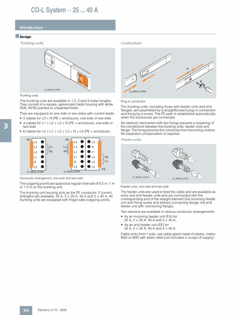
Trunking units
Trunking units
The trunking units are available in 1.5, 2 and 3 meter lengths. They consist of a square, galvanized metal housing with white (RAL 9016) painted or unpainted finish.
They are equipped on one side or two sides with current leads:• 2 cables for L3 + N (PE = enclosure), one-side or two-side• 4 cables for L1 + L2 + L3 + N (PE = enclosure), one-side or
two-side• 6 cables for L4 + L1 + L2 + L3 + N + L5 (PE = enclosure).
Conductor arrangement, one-side and two-side
The outgoing points are spaced at regular intervals of 0.5 m, 1 m or 1.5 m on the trunking unit.
The trunking unit housing acts as the PE conductor. 2 current strengths are available: 25 A, 2 × 25 A, 40 A and 2 × 40 A. All trunking units are equipped with finger-safe outgoing points.
Connections
Plug-in connection
The trunking units, including those with feeder units and end flanges, are assembled by a straightforward plug-in connection and fixing by a screw. The PE path is established automatically when the enclosures are connected.
An interlock mechanism with two fixings prevents a loosening of the connections between the trunking units, feeder units and flange. The fixing prevents the connection from becoming undone. No expansion compensation is required.
Feeder units
Feeder units, one-side and two-side
The feeder units are used to feed the cable and are available as entry and end feeder units and are connected with the corresponding end of the straight element (the incoming feeder unit with fixing screw and without connecting flange, the end feeder unit with connecting flange).
Two versions are available in various conductor arrangements:• As an incoming feeder unit (EA) for
25 A, 2 × 25 A, 40 A and 2 × 40 A,• As an end feeder unit (EE) for
25 A, 2 × 25 A, 40 A and 2 × 40 A.
Cable entry from 1 side; use cable gland made of plastic, metric M25 or M32 with strain relief (not included in scope of supply).
G_NSV0_01501
L4
L3
L2
L1
N
L5
PE
L3N2
G_NSV0_01502 G_NSV0_01503
L4
L3
L2
L1
N
L5
PE
PE
L3N2
L5
N
L1
L2
L3
N2L3
L4
G_NSV0_01504
A
B
G_NSV0_01510 G_NSV0_01511
LV70_03.book Seite 4 Mittwoch, 24. September 2008 4:55 16

CD-L System — 25 ... 40 A
Introduction
3/5Siemens LV 70 · 2009
3
End flanges
End flanges, one-side and two-side
The end flanges are used to close the end of each conductor. These flanges provide touch protection against direct contact at the ends of the busbar line.
They are available in two versions for connecting with the corresponding straight element.• End flange (EA-EF); can be used if the cable line begins with
an incoming feeder unit, • End flange (EE-EF); can be used if the cable line begins with
an end feeder unit.
Junction units
Junction units, one-side and two-side
The flexible junction units enable a change of the busbar line progression in each direction and also used for bridging obstacles along the busbar.
Outgoing plugs
Insulated outgoing plugs are used for taking current from the outgoing points on the trunking units. They can be mounted and removed by hand. This is even possible with live busbars.
Standard outgoing plugs
Standard outgoing plug
Single-phase outgoing plugs with transparent top part to allow pole selection are available. They can be used on standard outgoing points or coded outgoing points. Standard outgoing plugs are identified by a gray base.
The outgoing plugs are available in the following versions:• 3-pole, without fuse, 16 A, Lx (phase can be changed
optionally to L1, L2, L3 ), N and PE• 3-pole, with fuse, 16 A and 6.3 A, Lx (phase can be changed
optionally to L1, L2, L3 ), N and PE
The outgoing plugs can be equipped with L4/L5 contacts to be used on the 7-conductor and 7+7-conductor trunking units.
Phase selection allows wiring of either single-phase circuits with separate neutral conductor (N/L1, N/L2, N/L3) or three-phase circuits with common neutral conductor (N/L1/L2/L3).
Standard outgoing plugs are fitted with a neutral conductor and a phase contact; with the withdrawable version of an additional mobile contact they can be used as outgoing plugs for three-phase circuits.
7 Mobile contacts
Mobile contacts, with and without fuse
They are intended for use in the outgoing plugs with phase selection to feed three-phase circuits.• 1-pole, 16 A, without fuse (blue color for the neutral conductor)• 1-pole, 16 A, without fuse (black color for the phase)• 1-pole, 10 A, with phase melting fuse 6.3 A (5 mm x 20 mm)• 1-pole, 16 A with phase melting fuse 10 A (8.5 mm x 31.5 mm)
G_NSV0_01508G_NSV0_01509
G_NSV0_01506 G_NSV0_01507
G_N
SV
0_01
512
G_N
SV
0_01
513
G_N
SV
0_01
514
G_N
SV
0_01
515
G_N
SV
0_01
516
LV70_03.book Seite 5 Mittwoch, 24. September 2008 4:55 16
CD-L System — 25 ... 40 A
Introduction
3/6 Siemens LV 70 · 2009
3
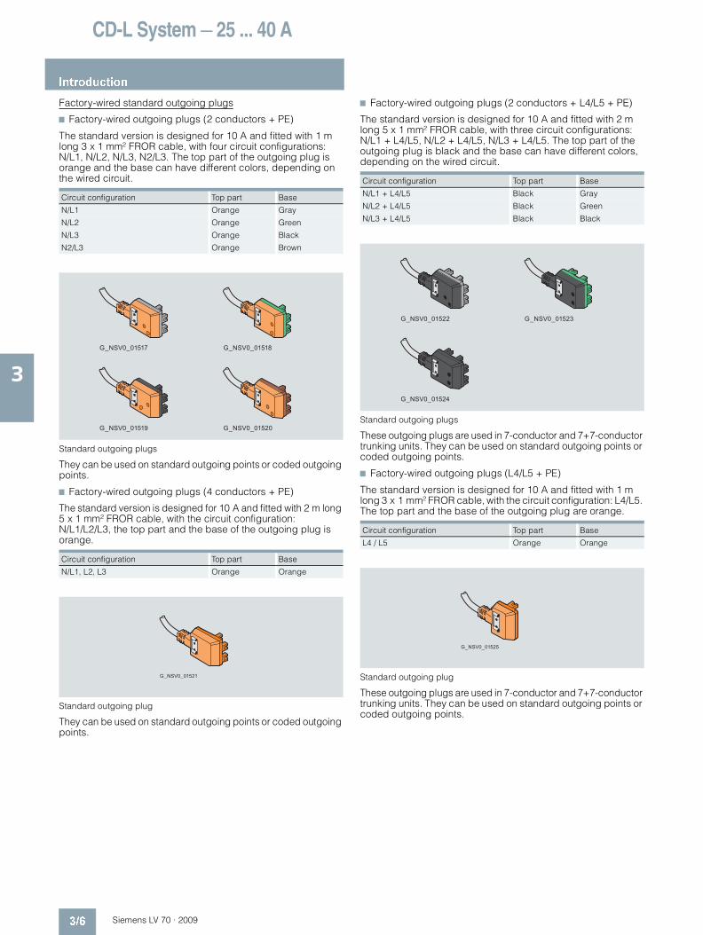
Factory-wired standard outgoing plugs
7 Factory-wired outgoing plugs (2 conductors + PE)
The standard version is designed for 10 A and fitted with 1 m long 3 x 1 mm² FROR cable, with four circuit configurations: N/L1, N/L2, N/L3, N2/L3. The top part of the outgoing plug is orange and the base can have different colors, depending on the wired circuit.
Standard outgoing plugs
They can be used on standard outgoing points or coded outgoing points.
7 Factory-wired outgoing plugs (4 conductors + PE)
The standard version is designed for 10 A and fitted with 2 m long 5 x 1 mm² FROR cable, with the circuit configuration: N/L1/L2/L3, the top part and the base of the outgoing plug is orange.
Standard outgoing plug
They can be used on standard outgoing points or coded outgoing points.
7 Factory-wired outgoing plugs (2 conductors + L4/L5 + PE)
The standard version is designed for 10 A and fitted with 2 m long 5 x 1 mm² FROR cable, with three circuit configurations: N/L1 + L4/L5, N/L2 + L4/L5, N/L3 + L4/L5. The top part of the outgoing plug is black and the base can have different colors, depending on the wired circuit.
Standard outgoing plugs
These outgoing plugs are used in 7-conductor and 7+7-conductor trunking units. They can be used on standard outgoing points or coded outgoing points.
7 Factory-wired outgoing plugs (L4/L5 + PE)
The standard version is designed for 10 A and fitted with 1 m long 3 x 1 mm² FROR cable, with the circuit configuration: L4/L5. The top part and the base of the outgoing plug are orange.
Standard outgoing plug
These outgoing plugs are used in 7-conductor and 7+7-conductor trunking units. They can be used on standard outgoing points or coded outgoing points.
Circuit configuration Top part Base
N/L1 Orange Gray
N/L2 Orange Green
N/L3 Orange Black
N2/L3 Orange Brown
Circuit configuration Top part Base
N/L1, L2, L3 Orange Orange
G_NSV0_01517 G_NSV0_01518
G_NSV0_01519 G_NSV0_01520
G_NSV0_01521
Circuit configuration Top part Base
N/L1 + L4/L5 Black Gray
N/L2 + L4/L5 Black Green
N/L3 + L4/L5 Black Black
Circuit configuration Top part Base
L4 / L5 Orange Orange
G_NSV0_01522 G_NSV0_01523
G_NSV0_01524
G_NSV0_01525
LV70_03.book Seite 6 Mittwoch, 24. September 2008 4:55 16

CD-L System — 25 ... 40 A
Introduction
3/7Siemens LV 70 · 2009
3
Coded outgoing plugs
Single-phase outgoing plugs with transparent top part to allow pole selection are available. The base can be red (KR) or white (KW). These outgoing plugs are mechanically coded and can only be used on coded outgoing points. • The (KR) outgoing plugs (red base) can only be used on
busbar systems with red outgoing point (KR version).• The (KW) outgoing plugs (white base) can only be used on busbar
systems with white outgoing point (KW or KRW version).
Coded outgoing plugs
The outgoing plugs are available in the following versions:• 3-pole, without fuse, 16 A, Lx (phase can be changed optionally
to L1, L2, L3), N and PE• 3-pole, with fuse, 16 A and 6.3 A, Lx (phase can be changed
optionally to L1, L2, L3), N and PE
Outgoing plugs can be equipped with L4/L5 contacts to be used with the 7-conductor and 7+7-conductor trunking units.
Phase selection allows wiring of either single-phase circuits with separate neutral conductor (N/L1, N/L2, N/L3) or three-phase circuits with common neutral conductor (N/L1/N2/L3).
Standard outgoing plugs are fitted with a neutral conductor and a phase contact, but with the withdrawable version of an additional mobile contact (see page 3/5), can be used as outgoing plugs for three-phase circuits.
Coded, wired outgoing plugs
7 Factory-wired coded outgoing plugs (2 conductors + PE) KR
The standard version is designed for 10 A and fitted with 1 m long 3 x 1 mm² FROR cable, with four circuit configurations: N/L1, N/L2, N/L3, N2/L3. The top part of the outgoing plug is orange and the base can have different colors, depending on the wired circuit.
Coded outgoing plugs
These mechanically coded outgoing plugs can only be used on coded outgoing points (colored red, KR version).
7 Factory-wired coded outgoing plugs (2 conductors + PE) KW
The standard version is designed for 10 A and fitted with 1 m long 3 x 1 mm² FROR cable, with four circuit configurations: N/L1, N/L2, N/L3, N2/L3. The top part of the outgoing plug is white and the base can have different colors, depending on the wired circuit.
Coded outgoing plugs
These mechanically coded outgoing plugs can only be used on coded outgoing points (colored white, KW version).
G_N
SV
0_01
526
G_N
SV
0_01
527
Circuit configuration Top part Base
N/L1 Red Gray
N/L2 Red Green
N/L3 Red Black
N2/L3 Red Brown
Circuit configuration Top part Base
N/L1 White Gray
N/L2 White Green
N/L3 White Black
N2/L3 White Brown
G_NSV0_01528 G_NSV0_01529
G_NSV0_01530 G_NSV0_01531
G_NSV0_01532 G_NSV0_01533
G_NSV0_01534 G_NSV0_01535
LV70_03.book Seite 7 Mittwoch, 24. September 2008 4:55 16

CD-L System — 25 ... 40 A
Introduction
3/8 Siemens LV 70 · 2009
3
Accessories
Suspension
The trunking unit profile allows attachment of the suspension and fixing brackets at any point of the trunking unit.
Standard fixing brackets
Fixing brackets, one-side and two-side
These brackets can be used:• For mounting the trunking units on the floor or on the ceiling• For suspending luminaires on the trunking unit.
The fixing brackets are secured to the ceiling by chains or steel wire using suitable suspension brackets.• Recommended spacing between fixing brackets 3 m.• Available for loads up to 12 kg.
Universal suspension brackets
Suspension brackets, one-side and two-side
These brackets can be used:• For suspending the trunking units on the wall, on the floor or
on the ceiling• For suspending the luminaires.
The suspension brackets are secured to the ceiling by chains or steel wire using suitable suspension brackets (open/closed). • Recommended spacing between fixing brackets 3 m.• Available for loads up to 25 kg.
Fixing brackets with hook
Fixing brackets with hook, one-side and two-side
These brackets can be used:• For mounting the trunking units on chains or steel wires,• For suspending luminaires on the trunking unit.
Open/closed hooks
Hooks, open and closed
These hooks can be used with the fixing/suspension brackets and fixing brackets for cable ducts:• For mounting the trunking unit on the ceiling with chains or
steel wires• For suspending luminaires on the trunking unit.
G_NSV0_01537 G_NSV0_01538
G_NSV0_01539 G_NSV0_01540
G_NSV0_01541 G_NSV0_01542
G_NSV0_01543 G_NSV0_01544
LV70_03.book Seite 8 Mittwoch, 24. September 2008 4:55 16

CD-L System — 25 ... 40 A
Introduction
3/9Siemens LV 70 · 2009
3
Cable duct
Cable duct (2 elements plugged together)
The cable duct is made of plastic (white), standard length 3 m. It is used for cables in auxiliary circuits. It is mounted on the trunking unit with the fixing brackets for cable ducts.
Fixing brackets for cable duct
Fixing bracket
They are used with the standard fixing brackets or universal suspension brackets for mounting the trunking units of the cable ducts on the ceiling, on the floor or on the wall. Combined with the open/closed hooks, they can be secured on the ceiling with chains or steel wires.
Cover
Cover
The cover is used to restore degree of protection IP55 to the previously used outgoing point after an outgoing plug has been removed from an outgoing point.
G_NSV0_01545
G_NSV0_01546
G_N
SV
0_01
536
LV70_03.book Seite 9 Mittwoch, 24. September 2008 4:55 16
CD-L System — 25 ... 40 A
General data
3/10 Siemens LV 70 · 2009
3
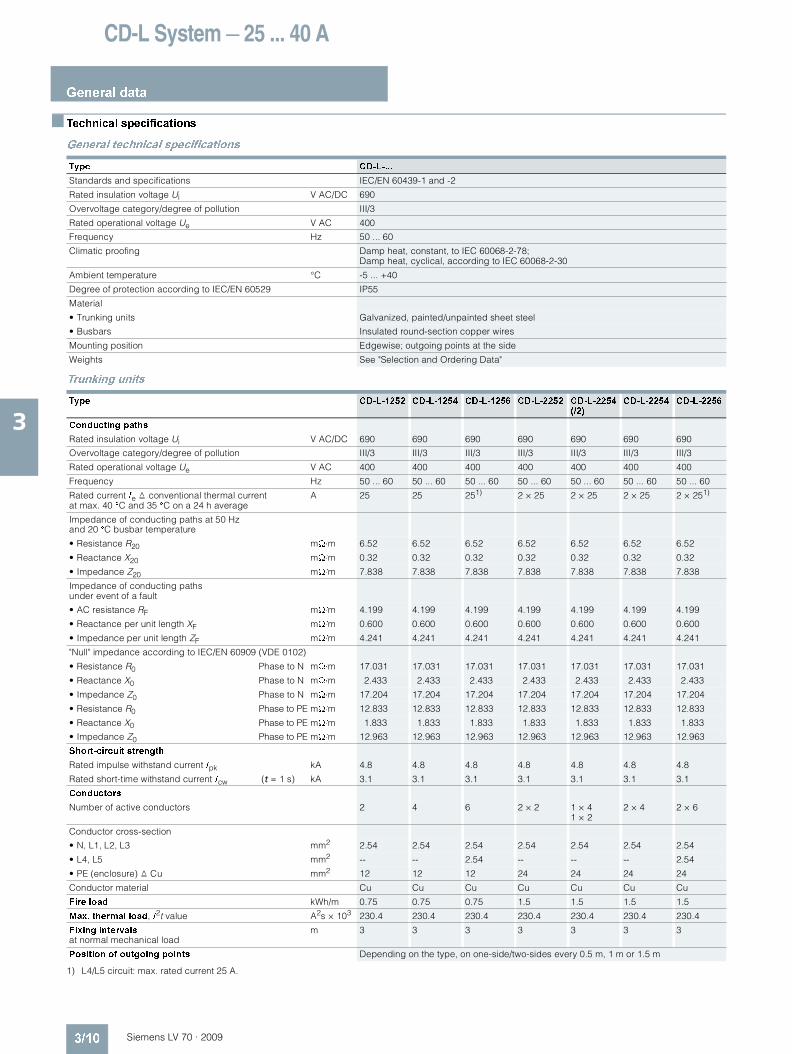
Technical specifications
General technical specifications
Trunking units
1) L4/L5 circuit: max. rated current 25 A.
Type CD-L-...
Standards and specifications IEC/EN 60439-1 and -2
Rated insulation voltage Ui V AC/DC 690
Overvoltage category/degree of pollution III/3
Rated operational voltage Ue V AC 400
Frequency Hz 50 ... 60
Climatic proofing Damp heat, constant, to IEC 60068-2-78; Damp heat, cyclical, according to IEC 60068-2-30
Ambient temperature °C -5 ... +40
Degree of protection according to IEC/EN 60529 IP55
Material
• Trunking units Galvanized, painted/unpainted sheet steel
• Busbars Insulated round-section copper wires
Mounting position Edgewise; outgoing points at the side
Weights See "Selection and Ordering Data"
Type CD-L-1252 CD-L-1254 CD-L-1256 CD-L-2252 CD-L-2254 (/2)
CD-L-2254 CD-L-2256
Conducting paths
Rated insulation voltage Ui V AC/DC 690 690 690 690 690 690 690
Overvoltage category/degree of pollution III/3 III/3 III/3 III/3 III/3 III/3 III/3
Rated operational voltage Ue V AC 400 400 400 400 400 400 400
Frequency Hz 50 ... 60 50 ... 60 50 ... 60 50 ... 60 50 ... 60 50 ... 60 50 ... 60
Rated current Ie � conventional thermal current at max. 40 °C and 35 °C on a 24 h average
A 25 25 251) 2 × 25 2 × 25 2 × 25 2 × 251)
Impedance of conducting paths at 50 Hzand 20 °C busbar temperature
• Resistance R20 mΩ/m 6.52 6.52 6.52 6.52 6.52 6.52 6.52
• Reactance X20 mΩ/m 0.32 0.32 0.32 0.32 0.32 0.32 0.32
• Impedance Z20 mΩ/m 7.838 7.838 7.838 7.838 7.838 7.838 7.838
Impedance of conducting paths under event of a fault
• AC resistance RF mΩ/m 4.199 4.199 4.199 4.199 4.199 4.199 4.199
• Reactance per unit length XF mΩ/m 0.600 0.600 0.600 0.600 0.600 0.600 0.600
• Impedance per unit length ZF mΩ/m 4.241 4.241 4.241 4.241 4.241 4.241 4.241
"Null" impedance according to IEC/EN 60909 (VDE 0102)
• Resistance R0 Phase to N mΩ/m 17.031 17.031 17.031 17.031 17.031 17.031 17.031
• Reactance X0 Phase to N mΩ/m 2.433 2.433 2.433 2.433 2.433 2.433 2.433
• Impedance Z0 Phase to N mΩ/m 17.204 17.204 17.204 17.204 17.204 17.204 17.204
• Resistance R0 Phase to PE mΩ/m 12.833 12.833 12.833 12.833 12.833 12.833 12.833
• Reactance X0 Phase to PE mΩ/m 1.833 1.833 1.833 1.833 1.833 1.833 1.833
• Impedance Z0 Phase to PE mΩ/m 12.963 12.963 12.963 12.963 12.963 12.963 12.963
Short-circuit strength
Rated impulse withstand current Ipk kA 4.8 4.8 4.8 4.8 4.8 4.8 4.8
Rated short-time withstand current Icw (t = 1 s) kA 3.1 3.1 3.1 3.1 3.1 3.1 3.1
Conductors
Number of active conductors 2 4 6 2 × 2 1 × 4 1 × 2
2 × 4 2 × 6
Conductor cross-section
• N, L1, L2, L3 mm2 2.54 2.54 2.54 2.54 2.54 2.54 2.54
• L4, L5 mm2 -- -- 2.54 -- -- -- 2.54
• PE (enclosure) � Cu mm2 12 12 12 24 24 24 24
Conductor material Cu Cu Cu Cu Cu Cu Cu
Fire load kWh/m 0.75 0.75 0.75 1.5 1.5 1.5 1.5
Max. thermal load, I2t value A2s × 103 230.4 230.4 230.4 230.4 230.4 230.4 230.4
Fixing intervals at normal mechanical load
m 3 3 3 3 3 3 3
Position of outgoing points Depending on the type, on one-side/two-sides every 0.5 m, 1 m or 1.5 m
LV70_03.book Seite 10 Mittwoch, 24. September 2008 4:55 16

CD-L System — 25 ... 40 A
General data
3/11Siemens LV 70 · 2009
3
1) L4/L5 circuit: max. rated current 25 A.
Feeder units, conductor cross-sections
Outgoing plugs
Type CD-L-1402 CD-L-1404 CD-L-1406 CD-L-2402 CD-L-2404 (/2)
CD-L-2404 CD-L-2406
Conducting paths
Rated insulation voltage Ui V AC/DC 690 690 690 690 690 690 690
Overvoltage category/degree of pollution III/3 III/3 III/3 III/3 III/3 III/3 III/3
Rated operational voltage Ue V AC 400 400 400 400 400 400 400
Frequency Hz 50 ... 60 50 ... 60 50 ... 60 50 ... 60 50 ... 60 50 ... 60 50 ... 60
Rated current Ie � conventional thermal current at max. 40 °C and 35 °C on a 24 h average
A 40 40 40 401) 2 × 40 40 401)
Impedance of conducting paths at 50 Hzand 20 °C busbar temperature
• Resistance R20 mΩ/m 2.7 2.7 2.7 2.7 2.7 2.7 2.7
• Reactance X20 mΩ/m 0.2 0.2 0.2 0.2 0.2 0.2 0.2
• Impedance Z20 mΩ/m 3.23 3.23 3.23 3.23 3.23 3.23 3.23
Impedance of conducting paths under event of a fault
• AC resistance RF mΩ/m 0.825 0.825 0.825 0.825 0.825 0.825 0.825
• Reactance per unit length XF mΩ/m 0.118 0.118 0.118 0.118 0.118 0.118 0.118
• Impedance per unit length ZF mΩ/m 0.833 0.833 0.833 0.833 0.833 0.833 0.833
"Null" impedance according to IEC/EN 60909 (VDE 0102)
• Resistance R0 Phase to N mΩ/m 8.035 8.035 8.035 8.035 8.035 8.035 8.035
• Reactance X0 Phase to N mΩ/m 1.147 1.147 1.147 1.147 1.147 1.147 1.147
• Impedance Z0 Phase to N mΩ/m 8.116 8.116 8.116 8.116 8.116 8.116 8.116
• Resistance R0 Phase to PE mΩ/m 7.210 7.210 7.210 7.210 7.210 7.210 7.210
• Reactance X0 Phase to PE mΩ/m 1.030 1.030 1.030 1.030 1.030 1.030 1.030
• Impedance Z0 Phase to PE mΩ/m 7.284 7.284 7.284 7.284 7.284 7.284 7.284
Short-circuit strength
Rated impulse withstand current Ipk kA 10.6 10.6 10.6 10.6 10.6 10.6 10.6
Rated short-time withstand current Icw (t = 1 s) kA 6.165 6.165 6.165 6.165 6.165 6.165 6.165
Conductors
Number of active conductors 2 4 6 2 × 2 1 × 4 1 × 2
2 × 4 2 × 6
Conductor cross-section
• N, L1, L2, L3 mm2 6.15 6.15 6.15 6.15 6.15 6.15 6.15
• L4, L5 mm2 2.54 2.54
• PE (enclosure) � Cu mm2 12 12 12 24 24 24 24
Conductor material Cu Cu Cu Cu Cu Cu Cu
Fire load kWh/m 0.75 0.75 0.75 1.5 1.5 1.5 1.5
Max. thermal load, I2t value A2s × 103 1123.6 1123.6 1123.6 1123.6 1123.6 1123.6 1123.6
Fixing intervals at normal mechanical load
m 3 3 3 3 3 3 3
Position of outgoing points Depending on the type, on one-side/two-sides every 0.5 m, 1 m or 1.5 m
Version Type N, L1, L2, L3 L4, L5 PE
min. mm2
max. mm2
min. mm2
max. mm2
min. mm2
max. mm2
Incoming feeder unit CD-L-...-EA 2.5 6 (f) 10 (so, st)
1.5 (f) 2.5 (so, st)
2.5 4 (f) 6 (so, st)
End feeder unit CD-L-...-EE 2.5 6 (f) 10 (so, st)
1.5 (f) 2.5 (so, st)
2.5 4 (f) 6 (so, st)
f = Finely stranded with end sleeve, so = solid, st = stranded
Type CD-L-A...
Version 3-, 5-pole or 5+2-pole
Rated current Ie A 6.3; 10 or 16
Switching capacity according to IEC/EN 60947-3
• Utilization category AC-20B
Connection Without or with permanently attached cable; the PE operates as a leading contact during connection and as a delayed contact during removal
Fuses Without or with fuse holder for cylindrical fuses Size 8.5 mm × 31.5 mm or 5 mm × 20 mm, type gG (IEC) or type gL (VDE) (quick)
LV70_03.book Seite 11 Mittwoch, 24. September 2008 4:55 16

CD-L System — 25 ... 40 A
Trunking units
3/12 Siemens LV 70 · 2009
3
Selection and ordering data
Unpainted trunking units with uncoded outgoing points (supplied from stock)
1) L4/L5 circuit: max. rated current 25 A.
Version Length Conductor configuration
Outgoing points DT Type Order No. PS* Weight per unit approx.
Number Distance
m m kg
Rated current Ie = 25 A, outgoing points on one side
Trunking unitsSheet-steel enclosure, unpainted, uncoded outgoing points
3 3 conductors 2 1.5 X CD-L-1252-3-1,5 8PS0300-3BF25 6 units 2.770
3 3 1 X CD-L-1252-3-1 8PS0301-3BF25 6 units 2.770
3 6 0.5 X CD-L-1252-3-0,5 8PS0302-3BF25 6 units 2.770
2 2 1 X CD-L-1252-2-1 8PS0300-2BF25 6 units 1.840
1.5 2 1 X CD-L-1252-1,5-1 8PS0300-1BF25 6 units 1.380
3 5 conductors 2 1.5 X CD-L-1254-3-1,5 8PS0300-3CF25 6 units 2.980
3 3 1 X CD-L-1254-3-1 8PS0301-3CF25 6 units 2.980
3 6 0.5 X CD-L-1254-3-0,5 8PS0302-3CF25 6 units 2.980
2 2 1 X CD-L-1254-2-1 8PS0300-2CF25 6 units 1.990
1.5 2 1 X CD-L-1254-1,5-1 8PS0300-1CF25 6 units 1.490
3 7 conductors1) 2 1.5 X CD-L-1256-3-1,5 8PS0300-3DF25 6 units 3.130
3 3 1 X CD-L-1256-3-1 8PS0301-3DF25 6 units 3.130
3 6 0.5 X CD-L-1256-3-0,5 8PS0302-3DF25 6 units 3.130
2 2 1 X CD-L-1256-2-1 8PS0300-2DF25 6 units 2.080
1.5 2 1 X CD-L-1256-1,5-1 8PS0300-1DF25 6 units 1.560
Rated current Ie = 2 × 25 A, outgoing points on two sides
Trunking unitsSheet-steel enclosure, unpainted, uncoded outgoing points
3 2 × 3 conductors 2 x 2 1.5 X CD-L-2252-3-1,5 8PS0300-3FF25 6 units 5.530
3 2 x 3 1 X CD-L-2252-3-1 8PS0301-3FF25 6 units 5.530
3 2 x 6 0.5 X CD-L-2252-3-0,5 8PS0302-3FF25 6 units 5.530
2 2 x 2 1 X CD-L-2252-2-1 8PS0300-2FF25 6 units 3.690
1.5 2 x 2 1 X CD-L-2252-1,5-1 8PS0300-1FF25 6 units 2.770
3 1 × 5 conductors1 × 3 conductors
2 x 2 1.5 X CD-L-2254/2-KR-3-1,5 8PS0303-3GF25 6 units 5.740
3 2 x 3 1 X CD-L-2254/2-KR-3-1 8PS0304-3GF25 6 units 5.740
3 2 x 6 0.5 X CD-L-2254/2-KR-3-0,5 8PS0305-3GF25 6 units 5.740
2 2 x 2 1 X CD-L-2254/2-KR-2-1 8PS0303-2GF25 6 units 3.830
1.5 2 x 2 1 X CD-L-2254/2-KR-1,5-1 8PS0303-1GF25 6 units 2.870
3 2 × 5 conductors 2 x 2 1.5 X CD-L-2254-3-1,5 8PS0300-3HF25 6 units 5.960
3 2 x 3 1 X CD-L-2254-3-1 8PS0301-3HF25 6 units 5.960
3 2 x 6 0.5 X CD-L-2254-3-0,5 8PS0302-3HF25 6 units 5.960
2 2 x 2 1 X CD-L-2254-2-1 8PS0300-2HF25 6 units 3.970
1.5 2 x 2 1 X CD-L-2254-1,5-1 8PS0300-1HF25 6 units 2.980
3 2 × 7 conductors1)
2 x 2 1.5 X CD-L-2256-3-1,5 8PS0300-3JF25 6 units 6.250
3 2 x 3 1 X CD-L-2256-3-1 8PS0301-3JF25 6 units 6.250
3 2 x 6 0.5 X CD-L-2256-3-0,5 8PS0302-3JF25 6 units 6.250
2 2 x 2 1 X CD-L-2256-2-1 8PS0300-2JF25 6 units 4.170
1.5 2 x 2 1 X CD-L-2256-1,5-1 8PS0300-1JF25 6 units 3.130
G_NSV0_01547
G_N
SV
0_01
549
L3
N
PEG
_NS
V0_
0155
0
L3L2L1N
PE
L3N2
G_N
SV
0_01
551 L4
L3L2L1NL5
PE
L3N2
G_NSV0_01548
G_N
SV
0_01
552
L3
N
PE
PE
N
L3
G_N
SV
0_01
553
L3L2L1N
PE
PE
L3N2
N
L3
G_N
SV
0_01
554
L3L2L1N
PE
PE
L3N2
NL1L2L3
N2L3
G_N
SV
0_01
555 L4
L3L2L1NL5
PE
PE
L3N2
L5NL1L2L3
N2L3
L4
LV70_03.book Seite 12 Mittwoch, 24. September 2008 4:55 16

CD-L System — 25 ... 40 A
Trunking units
3/13Siemens LV 70 · 2009
3
1) L4/L5 circuit: max. rated current 25 A.
Version Length Conductor configuration
Outgoing points DT Type Order No. PS* Weight per unit approx.
Number Distance
m m kg
Rated current Ie = 40 A, outgoing points on one side
Trunking unitsSheet-steel enclosure, unpainted, uncoded outgoing points
3 3 conductors 2 1.5 X CD-L-1402-3-1,5 8PS0300-3BF40 6 units 2.960
3 3 1 X CD-L-1402-3-1 8PS0301-3BF40 6 units 2.960
3 6 0.5 X CD-L-1402-3-0,5 8PS0302-3BF40 6 units 2.960
2 2 1 X CD-L-1402-2-1 8PS0300-2BF40 6 units 1.970
1.5 2 1 X CD-L-1402-1,5-1 8PS0300-1BF40 6 units 1.480
3 5 conductors 2 1.5 X CD-L-1404-3-1,5 8PS0300-3CF40 6 units 3.330
3 3 1 X CD-L-1404-3-1 8PS0301-3CF40 6 units 3.330
3 6 0.5 X CD-L-1404-3-0,5 8PS0302-3CF40 6 units 3.330
2 2 1 X CD-L-1404-2-1 8PS0300-2CF40 6 units 2.220
1.5 2 1 X CD-L-1404-1,5-1 8PS0300-1CF40 6 units 1.660
3 7 conductors1) 2 1.5 X CD-L-1406-3-1,5 8PS0300-3DF40 6 units 3.480
3 3 1 X CD-L-1406-3-1 8PS0301-3DF40 6 units 3.480
3 6 0.5 X CD-L-1406-3-0,5 8PS0302-3DF40 6 units 3.480
2 2 1 X CD-L-1406-2-1 8PS0300-2DF40 6 units 2.320
1.5 2 1 X CD-L-1406-1,5-1 8PS0300-1DF40 6 units 1.740
Rated current Ie = 2 × 40 A, outgoing points on two sides
Trunking unitsSheet-steel enclosure, unpainted, uncoded outgoing points
3 2 × 3 conductors 2 x 2 1.5 X CD-L-2402-3-1,5 8PS0300-3FF40 6 units 5.920
3 2 x 3 1 X CD-L-2402-3-1 8PS0301-3FF40 6 units 5.920
3 2 x 6 0.5 X CD-L-2402-3-0,5 8PS0302-3FF40 6 units 5.920
2 2 x 2 1 X CD-L-2402-2-1 8PS0300-2FF40 6 units 3.940
1.5 2 x 2 1 X CD-L-2402-1,5-1 8PS0300-1FF40 6 units 2.960
3 1 × 5 conductors1 × 3 conductors
2 x 2 1.5 X CD-L-2404/2-KR-3-1,5 8PS0303-3GF40 6 units 6.290
3 2 x 3 1 X CD-L-2404/2-KR-3-1 8PS0304-3GF40 6 units 6.290
3 2 x 6 0.5 X CD-L-2404/2-KR-3-0,5 8PS0305-3GF40 6 units 6.290
2 2 x 2 1 X CD-L-2404/2-KR-2-1 8PS0303-2GF40 6 units 4.190
1.5 2 x 2 1 X CD-L-2404/2-KR-1,5-1 8PS0303-1GF40 6 units 3.140
3 2 × 5 conductors 2 x 2 1.5 X CD-L-2404-3-1,5 8PS0300-3HF40 6 units 6.650
3 2 x 3 1 X CD-L-2404-3-1 8PS0301-3HF40 6 units 6.650
3 2 x 6 0.5 X CD-L-2404-3-0,5 8PS0302-3HF40 6 units 6.650
2 2 x 2 1 X CD-L-2404-2-1 8PS0300-2HF40 6 units 4.440
1.5 2 x 2 1 X CD-L-2404-1,5-1 8PS0300-1HF40 6 units 3.330
3 2 × 7 conductors1)
2 x 2 1.5 X CD-L-2406-3-1,5 8PS0300-3JF40 6 units 6.950
3 2 x 3 1 X CD-L-2406-3-1 8PS0301-3JF40 6 units 6.950
3 2 x 6 0.5 X CD-L-2406-3-0,5 8PS0302-3JF40 6 units 6.950
2 2 x 2 1 X CD-L-2406-2-1 8PS0300-2JF40 6 units 4.630
1.5 2 x 2 1 X CD-L-2406-1,5-1 8PS0300-1JF40 6 units 3.470
G_NSV0_01547
G_N
SV
0_01
549
L3
N
PE
G_N
SV
0_01
550
L3L2L1N
PE
L3N2
G_N
SV
0_01
551 L4
L3L2L1NL5
PE
L3N2
G_NSV0_01548
G_N
SV
0_01
552
L3
N
PE
PE
N
L3
G_N
SV
0_01
553
L3L2L1N
PE
PE
L3N2
N
L3
G_N
SV
0_01
554
L3L2L1N
PE
PE
L3N2
NL1L2L3
N2L3
G_N
SV
0_01
555 L4
L3L2L1NL5
PE
PE
L3N2
L5NL1L2L3
N2L3
L4
LV70_03.book Seite 13 Mittwoch, 24. September 2008 4:55 16
CD-L System — 25 ... 40 A
Trunking units
3/14 Siemens LV 70 · 2009
3
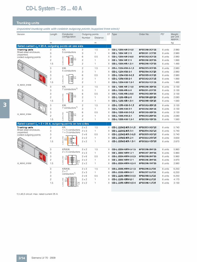
Unpainted trunking units with codable outgoing points (supplied from stock)
1) L4/L5 circuit: max. rated current 25 A.
Version Length Conductor configuration
Outgoing points DT Type Order No. PS* Weight per unit approx.
Number Distance
m m kg
Rated current Ie = 25 A, outgoing points on one side
Trunking unitsSheet-steel enclosure, unpainted, coded outgoing points
3 KR, 5 conductors
2 1.5 X CD-L-1254-KR-3-1,5 8PS0310-3CF25 6 units 2.980
3 3 1 X CD-L-1254-KR-3-1 8PS0311-3CF25 6 units 2.980
3 6 0.5 X CD-L-1254-KR-3-0,5 8PS0312-3CF25 6 units 2.980
2 2 1 X CD-L-1254-KR-2-1 8PS0310-2CF25 6 units 1.990
1.5 2 1 X CD-L-1254-KR-1,5-1 8PS0310-1CF25 6 units 1.490
3 KW, 5 conductors
2 1.5 X CD-L-1254-KW-3-1,5 8PS0313-3CF25 6 units 2.980
3 3 1 X CD-L-1254-KW-3-1 8PS0314-3CF25 6 units 2.980
3 6 0.5 X CD-L-1254-KW-3-0,5 8PS0315-3CF25 6 units 2.980
2 2 1 X CD-L-1254-KW-2-1 8PS0313-2CF25 6 units 1.990
1.5 2 1 X CD-L-1254-KW-1,5-1 8PS0313-1CF25 6 units 1.490
3 KR, 7 conductors1)
2 1.5 X CD-L-1256-KR-3-1,5 8PS0310-3DF25 6 units 3.130
3 3 1 X CD-L-1256-KR-3-1 8PS0311-3DF25 6 units 3.130
3 6 0.5 X CD-L-1256-KR-3-0,5 8PS0312-3DF25 6 units 3.130
2 2 1 X CD-L-1256-KR-2-1 8PS0310-2DF25 6 units 2.080
1.5 2 1 X CD-L-1256-KR-1,5-1 8PS0310-1DF25 6 units 1.560
3 KW, 7 conductors1)
2 1.5 X CD-L-1256-KW-3-1,5 8PS0313-3DF25 6 units 3.130
3 3 1 X CD-L-1256-KW-3-1 8PS0314-3DF25 6 units 3.130
3 6 0.5 X CD-L-1256-KW-3-0,5 8PS0315-3DF25 6 units 3.130
2 2 1 X CD-L-1256-KW-2-1 8PS0313-2DF25 6 units 2.080
1.5 2 1 X CD-L-1256-KW-1,5-1 8PS0313-1DF25 6 units 1.560
Rated current Ie = 2 × 25 A, outgoing points on two sides
Trunking unitsSheet-steel enclosure, unpainted, coded outgoing points
3 KR, 1 × 5 conductors1 × 3 conductors
2 x 2 1.5 X CD-L-2254/2-KR-3-1,5 8PS0303-3GF25 6 units 5.740
3 2 x 3 1 X CD-L-2254/2-KR-3-1 8PS0304-3GF25 6 units 5.740
3 2 x 6 0.5 X CD-L-2254/2-KR-3-0,5 8PS0305-3GF25 6 units 5.740
2 2 x 2 1 X CD-L-2254/2-KR-2-1 8PS0303-2GF25 6 units 3.830
1.5 2 x 2 1 X CD-L-2254/2-KR-1,5-1 8PS0303-1GF25 6 units 2.870
3 KR/KW, 2 × 5 conductors
2 x 2 1.5 X CD-L-2254-KRW-3-1,5 8PS0316-3HF25 6 units 5.960
3 2 x 3 1 X CD-L-2254-KRW-3-1 8PS0317-3HF25 6 units 5.960
3 2 x 6 0.5 X CD-L-2254-KRW-3-0,5 8PS0318-3HF25 6 units 5.960
2 2 x 2 1 X CD-L-2254-KRW-2-1 8PS0316-2HF25 6 units 3.970
1.5 2 x 2 1 X CD-L-2254-KRW-1,5-1 8PS0316-1HF25 6 units 2.980
3 KR/KW, 2 × 7 conductors1)
2 x 2 1.5 X CD-L-2256-KRW-3-1,5 8PS0316-3JF25 6 units 6.250
3 2 x 3 1 X CD-L-2256-KRW-3-1 8PS0317-3JF25 6 units 6.250
3 2 x 6 0.5 X CD-L-2256-KRW-3-0,5 8PS0318-3JF25 6 units 6.250
2 2 x 2 1 X CD-L-2256-KRW-2-1 8PS0316-2JF25 6 units 4.170
1.5 2 x 2 1 X CD-L-2256-KRW-1,5-1 8PS0316-1JF25 6 units 3.130
G_NSV0_01558
G_NSV0_01564
G_N
SV
0_01
560
L3L2L1N
PEL3N2
G_N
SV
0_01
561
L3L2L1N
PEL3N2
G_N
SV
0_01
562 L4
L3L2L1NL5
PEL3N2
G_N
SV
0_01
563 L5
L3L2L1NL4
PEL3N2
G_NSV0_01559
G_N
SV
0_01
553
L3L2L1N
PE
PE
L3N2
N
L3
G_N
SV
0_01
565
L3L2L1N
PE
PE
L3N2
NL1L2L3
N2L3
L4L3L2L1NL5
PE
PE
L3N2
L5NL1L2L3
N2L3
L4G_N
SV
0_01
566
LV70_03.book Seite 14 Mittwoch, 24. September 2008 4:55 16
CD-L System — 25 ... 40 A
Trunking units
3/15Siemens LV 70 · 2009
3
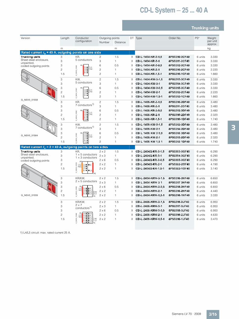
1) L4/L5 circuit: max. rated current 25 A.
Version Length Conductor configuration
Outgoing points DT Type Order No. PS* Weight per unit approx.
Number Distance
m m kg
Rated current Ie = 40 A, outgoing points on one side
Trunking unitsSheet-steel enclosure, unpainted, coded outgoing points
3 KR, 5 conductors
2 1.5 X CD-L-1404-KR-3-1,5 8PS0310-3CF40 6 units 3.330
3 3 1 X CD-L-1404-KR-3-1 8PS0311-3CF40 6 units 3.330
3 6 0.5 X CD-L-1404-KR-3-0,5 8PS0312-3CF40 6 units 3.330
2 2 1 X CD-L-1404-KR-2-1 8PS0310-2CF40 6 units 2.220
1.5 2 1 X CD-L-1404-KR-1,5-1 8PS0310-1CF40 6 units 1.660
3 KW, 5 conductors
2 1.5 X CD-L-1404-KW-3-1,5 8PS0313-3CF40 6 units 3.330
3 3 1 X CD-L-1404-KW-3-1 8PS0314-3CF40 6 units 3.330
3 6 0.5 X CD-L-1404-KW-3-0,5 8PS0315-3CF40 6 units 3.330
2 2 1 X CD-L-1404-KW-2-1 8PS0313-2CF40 6 units 2.220
1.5 2 1 X CD-L-1404-KW-1,5-1 8PS0313-1CF40 6 units 1.660
3 KR, 7 conductors1)
2 1.5 X CD-L-1406-KR-3-1,5 8PS0310-3DF40 6 units 3.480
3 3 1 X CD-L-1406-KR-3-1 8PS0311-3DF40 6 units 3.480
3 6 0.5 X CD-L-1406-KR-3-0,5 8PS0312-3DF40 6 units 3.480
2 2 1 X CD-L-1406-KR-2-1 8PS0310-2DF40 6 units 2.320
1.5 2 1 X CD-L-1406-KR-1,5-1 8PS0310-1DF40 6 units 1.740
3 KW, 7 conductors1)
2 1.5 X CD-L-1406-KW-3-1,5 8PS0313-3DF40 6 units 3.480
3 3 1 X CD-L-1406-KW-3-1 8PS0314-3DF40 6 units 3.480
3 6 0.5 X CD-L-1406-KW-3-0,5 8PS0315-3DF40 6 units 3.480
2 2 1 X CD-L-1406-KW-2-1 8PS0313-2DF40 6 units 2.320
1.5 2 1 X CD-L-1406-KW-1,5-1 8PS0313-1DF40 6 units 1.740
Rated current Ie = 2 × 40 A, outgoing points on two sides
Trunking unitsSheet-steel enclosure, unpainted, coded outgoing points
3 KR, 1 × 5 conductors1 × 3 conductors
2 x 2 1.5 X CD-L-2404/2-KR-3-1,5 8PS0303-3GF40 6 units 6.290
3 2 x 3 1 X CD-L-2404/2-KR-3-1 8PS0304-3GF40 6 units 6.290
3 2 x 6 0.5 X CD-L-2404/2-KR-3-0,5 8PS0305-3GF40 6 units 6.290
2 2 x 2 1 X CD-L-2404/2-KR-2-1 8PS0303-2GF40 6 units 4.190
1.5 2 x 2 1 X CD-L-2404/2-KR-1,5-1 8PS0303-1GF40 6 units 3.140
3 KR/KW, 2 × 5 conductors
2 x 2 1.5 X CD-L-2404-KRW-3-1,5 8PS0316-3HF40 6 units 6.650
3 2 x 3 1 X CD-L-2404-KRW-3-1 8PS0317-3HF40 6 units 6.650
3 2 x 6 0.5 X CD-L-2404-KRW-3-0,5 8PS0318-3HF40 6 units 6.650
2 2 x 2 1 X CD-L-2404-KRW-2-1 8PS0316-2HF40 6 units 4.440
1.5 2 x 2 1 X CD-L-2404-KRW-1,5-1 8PS0316-1HF40 6 units 3.330
3 KR/KW, 2 × 7 conductors1)
2 x 2 1.5 X CD-L-2406-KRW-3-1,5 8PS0316-3JF40 6 units 6.950
3 2 x 3 1 X CD-L-2406-KRW-3-1 8PS0317-3JF40 6 units 6.950
3 2 x 6 0.5 X CD-L-2406-KRW-3-0,5 8PS0318-3JF40 6 units 6.950
2 2 x 2 1 X CD-L-2406-KRW-2-1 8PS0316-2JF40 6 units 4.630
1.5 2 x 2 1 X CD-L-2406-KRW-1,5-1 8PS0316-1JF40 6 units 3.470
G_NSV0_01558
G_NSV0_01564
G_N
SV
0_01
560
L3L2L1N
PEL3N2
G_N
SV
0_01
561
L3L2L1N
PEL3N2
G_N
SV
0_01
562 L4
L3L2L1NL5
PEL3N2
G_N
SV
0_01
563 L5
L3L2L1NL4
PEL3N2
G_NSV0_01559
G_N
SV
0_01
553
L3L2L1N
PE
PE
L3N2
N
L3
G_N
SV
0_01
565
L3L2L1N
PE
PE
L3N2
NL1L2L3
N2L3
L4L3L2L1NL5
PE
PE
L3N2
L5NL1L2L3
N2L3
L4G_N
SV
0_01
566
LV70_03.book Seite 15 Mittwoch, 24. September 2008 4:55 16

CD-L System — 25 ... 40 A
Trunking units
3/16 Siemens LV 70 · 2009
3
Painted trunking units with uncoded outgoing points (delivery on request)
1) L4/L5 circuit: max. rated current 25 A.
Version Length Conductor configuration
Outgoing points DT Type Order No. PS* Weight per unit approx.
Number Distance
m m kg
Rated current Ie = 25 A, outgoing points on one side
Trunking unitsSheet-steel enclosure, painted, white (RAL 9016), uncoded outgoing points
3 3 conductors 2 1.5 X CD-L-1252-3-1,5-L 8PS1300-3BF25 6 units 2.770
3 3 1 X CD-L-1252-3-1-L 8PS1301-3BF25 6 units 2.770
3 6 0.5 X CD-L-1252-3-0,5-L 8PS1302-3BF25 6 units 2.770
2 2 1 X CD-L-1252-2-1-L 8PS1300-2BF25 6 units 1.840
1.5 2 1 X CD-L-1252-1,5-1-L 8PS1300-1BF25 6 units 1.380
3 5 conductors 2 1.5 X CD-L-1254-3-1,5-L 8PS1300-3CF25 6 units 2.980
3 3 1 X CD-L-1254-3-1-L 8PS1301-3CF25 6 units 2.980
3 6 0.5 X CD-L-1254-3-0,5-L 8PS1302-3CF25 6 units 2.980
2 2 1 X CD-L-1254-2-1-L 8PS1300-2CF25 6 units 1.990
1.5 2 1 X CD-L-1254-1,5-1-L 8PS1300-1CF25 6 units 1.490
3 7 conductors1) 2 1.5 X CD-L-1256-3-1,5-L 8PS1300-3DF25 6 units 3.480
3 3 1 X CD-L-1256-3-1-L 8PS1301-3DF25 6 units 3.480
3 6 0.5 X CD-L-1256-3-0,5-L 8PS1302-3DF25 6 units 3.480
2 2 1 X CD-L-1256-2-1-L 8PS1300-2DF25 6 units 2.320
1.5 2 1 X CD-L-1256-1,5-1-L 8PS1300-1DF25 6 units 1.740
Rated current Ie = 2 × 25 A, outgoing points on two sides
Trunking unitsSheet-steel enclosure, painted, white (RAL 9016), uncoded outgoing points
3 2 × 3 conductors 2 x 2 1.5 X CD-L-2252-3-1,5-L 8PS1300-3FF25 6 units 5.530
3 2 x 3 1 X CD-L-2252-3-1-L 8PS1301-3FF25 6 units 5.530
3 2 x 6 0.5 X CD-L-2252-3-0,5-L 8PS1302-3FF25 6 units 5.530
2 2 x 2 1 X CD-L-2252-2-1-L 8PS1300-2FF25 6 units 3.690
1.5 2 x 2 1 X CD-L-2252-1,5-1-L 8PS1300-1FF25 6 units 2.770
3 1 × 5 conductors1 × 3 conductors
2 x 2 1.5 X CD-L-2254/2-KR-3-1,5-L 8PS1303-3GF25 6 units 5.740
3 2 x 3 1 X CD-L-2254/2-KR-3-1-L 8PS1304-3GF25 6 units 5.740
3 2 x 6 0.5 X CD-L-2254/2-KR-3-0,5-L 8PS1305-3GF25 6 units 5.740
2 2 x 2 1 X CD-L-2254/2-KR-2-1-L 8PS1303-2GF25 6 units 3.830
1.5 2 x 2 1 X CD-L-2254/2-KR-1,5-1-L 8PS1303-1GF25 6 units 2.870
3 2 × 5 conductors 2 x 2 1.5 X CD-L-2254-3-1,5-L 8PS1300-3HF25 6 units 5.960
3 2 x 3 1 X CD-L-2254-3-1-L 8PS1301-3HF25 6 units 5.960
3 2 x 6 0.5 X CD-L-2254-3-0,5-L 8PS1302-3HF25 6 units 5.960
2 2 x 2 1 X CD-L-2254-2-1-L 8PS1300-2HF25 6 units 3.970
1.5 2 x 2 1 X CD-L-2254-1,5-1-L 8PS1300-1HF25 6 units 2.980
3 2 × 7 conductors1)
2 x 2 1.5 X CD-L-2256-3-1,5-L 8PS1300-3JF25 6 units 6.250
3 2 x 3 1 X CD-L-2256-3-1-L 8PS1301-3JF25 6 units 6.250
3 2 x 6 0.5 X CD-L-2256-3-0,5-L 8PS1302-3JF25 6 units 6.250
2 2 x 2 1 X CD-L-2256-2-1-L 8PS1300-2JF25 6 units 4.170
1.5 2 x 2 1 X CD-L-2256-1,5-1-L 8PS1300-1JF25 6 units 3.130
G_NSV0_01556
G_N
SV
0_01
549
L3
N
PE
G_N
SV
0_01
550
L3L2L1N
PE
L3N2
G_N
SV
0_01
551 L4
L3L2L1NL5
PE
L3N2
G_NSV0_01557
G_N
SV
0_01
552
L3
N
PE
PE
N
L3
G_N
SV
0_01
553
L3L2L1N
PE
PE
L3N2
N
L3
G_N
SV
0_01
554
L3L2L1N
PE
PE
L3N2
NL1L2L3
N2L3
G_N
SV
0_01
555 L4
L3L2L1NL5
PE
PE
L3N2
L5NL1L2L3
N2L3
L4
LV70_03.book Seite 16 Mittwoch, 24. September 2008 4:55 16

CD-L System — 25 ... 40 A
Trunking units
3/17Siemens LV 70 · 2009
3
1) L4/L5 circuit: max. rated current 25 A.
Version Length Conductor configuration
Outgoing points DT Type Order No. PS* Weight per unit approx.
Number Distance
m m kg
Rated current Ie = 40 A, outgoing points on one side
Trunking unitsSheet-steel enclosure, painted, white (RAL 9016), uncoded outgoing points
3 3 conductors 2 1.5 X CD-L-1402-3-1,5-L 8PS1300-3BF40 6 units 2.960
3 3 1 X CD-L-1402-3-1-L 8PS1301-3BF40 6 units 2.960
3 6 0.5 X CD-L-1402-3-0,5-L 8PS1302-3BF40 6 units 2.960
2 2 1 X CD-L-1402-2-1-L 8PS1300-2BF40 6 units 1.970
1.5 2 1 X CD-L-1402-1,5-1-L 8PS1300-1BF40 6 units 1.480
3 5 conductors 2 1.5 X CD-L-1404-3-1,5-L 8PS1300-3CF40 6 units 3.330
3 3 1 X CD-L-1404-3-1-L 8PS1301-3CF40 6 units 3.330
3 6 0.5 X CD-L-1404-3-0,5-L 8PS1302-3CF40 6 units 3.330
2 2 1 X CD-L-1404-2-1-L 8PS1300-2CF40 6 units 2.220
1.5 2 1 X CD-L-1404-1,5-1-L 8PS1300-1CF40 6 units 1.660
3 7 conductors1) 2 1.5 X CD-L-1406-3-1,5-L 8PS1300-3DF40 6 units 3.480
3 3 1 X CD-L-1406-3-1-L 8PS1301-3DF40 6 units 3.480
3 6 0.5 X CD-L-1406-3-0,5-L 8PS1302-3DF40 6 units 3.480
2 2 1 X CD-L-1406-2-1-L 8PS1300-2DF40 6 units 2.320
1.5 2 1 X CD-L-1406-1,5-1-L 8PS1300-1DF40 6 units 1.740
Rated current Ie = 2 × 40 A, outgoing points on two sides
Trunking unitsSheet-steel enclosure, painted, white (RAL 9016), uncoded outgoing points
3 2 × 3 conductors 2 x 2 1.5 X CD-L-2402-3-1,5-L 8PS1300-3FF40 6 units 5.920
3 2 x 3 1 X CD-L-2402-3-1-L 8PS1301-3FF40 6 units 5.920
3 2 x 6 0.5 X CD-L-2402-3-0,5-L 8PS1302-3FF40 6 units 5.920
2 2 x 2 1 X CD-L-2402-2-1-L 8PS1300-2FF40 6 units 3.940
1.5 2 x 2 1 X CD-L-2402-1,5-1-L 8PS1300-1FF40 6 units 2.960
3 1 × 5 conductors1 × 3 conductors
2 x 2 1.5 X CD-L-2404/2-KR-3-1,5-L 8PS1303-3GF40 6 units 6.290
3 2 x 3 1 X CD-L-2404/2-KR-3-1-L 8PS1304-3GF40 6 units 6.290
3 2 x 6 0.5 X CD-L-2404/2-KR-3-0,5-L 8PS1305-3GF40 6 units 6.290
2 2 x 2 1 X CD-L-2404/2-KR-2-1-L 8PS1303-2GF40 6 units 4.190
1.5 2 x 2 1 X CD-L-2404/2-KR-1,5-1-L 8PS1303-1GF40 6 units 3.140
3 2 × 5 conductors 2 x 2 1.5 X CD-L-2404-3-1,5-L 8PS1300-3HF40 6 units 6.650
3 2 x 3 1 X CD-L-2404-3-1-L 8PS1301-3HF40 6 units 6.650
3 2 x 6 0.5 X CD-L-2404-3-0,5-L 8PS1302-3HF40 6 units 6.650
2 2 x 2 1 X CD-L-2404-2-1-L 8PS1300-2HF40 6 units 4.440
1.5 2 x 2 1 X CD-L-2404-1,5-1-L 8PS1300-1HF40 6 units 3.330
3 2 × 7 conductors1)
2 x 2 1.5 X CD-L-2406-3-1,5-L 8PS1300-3JF40 6 units 6.950
3 2 x 3 1 X CD-L-2406-3-1-L 8PS1301-3JF40 6 units 6.950
3 2 x 6 0.5 X CD-L-2406-3-0,5-L 8PS1302-3JF40 6 units 6.950
2 2 x 2 1 X CD-L-2406-2-1-L 8PS1300-2JF40 6 units 4.630
1.5 2 x 2 1 X CD-L-2406-1,5-1-L 8PS1300-1JF40 6 units 3.470
G_NSV0_01556
G_N
SV
0_01
549
L3
N
PE
G_N
SV
0_01
550
L3L2L1N
PE
L3N2
G_N
SV
0_01
551 L4
L3L2L1NL5
PE
L3N2
G_NSV0_01557
G_N
SV
0_01
552
L3
N
PE
PE
N
L3
G_N
SV
0_01
553
L3L2L1N
PE
PE
L3N2
N
L3
G_N
SV
0_01
554
L3L2L1N
PE
PE
L3N2
NL1L2L3
N2L3
G_N
SV
0_01
555 L4
L3L2L1NL5
PE
PE
L3N2
L5NL1L2L3
N2L3
L4
LV70_03.book Seite 17 Mittwoch, 24. September 2008 4:55 16

CD-L System — 25 ... 40 A
Feeder units
3/18 Siemens LV 70 · 2009
3
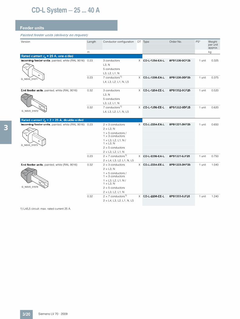
Overview
The feeder units are installed at the beginning of a busbar line. They are available as incoming and end feeder units and are connected with the corresponding end of the straight element (the incoming feeder unit without connecting flange, the end feeder unit with connecting flange).
The two circuits are mechanically separated on two-sided busbar elements.
Enclosure material
Connection boxes: thermoplastConnection point: galvanized metal enclosure
Conductor cross-sections
N/L1/L2/L3: max. cable diameter 10 mm2
L4/L5: max. cable diameter 2.5 mm2
PU: max. cable diameter 6 mm2
Selection and ordering data
Unpainted feeder units (supplied from stock)
1) L4/L5 circuit: max. rated current 25 A.
Version Length Conductor configuration DT Type Order No. PS* Weight per unit approx.
m kg
Rated current Ie = 25 A, one-sided
Incoming feeder units, unpainted (coded KR, KW)
0.23 3 conductors X CD-L-1254-EA 8PS0330-0CF25 1 unit 0.325
L3, N
5 conductors
L3, L2, L1, N
0.23 7 conductors1) X CD-L-1256-EA 8PS0330-0DF25 1 unit 0.375
L4, L3, L2, L1, N, L5
End feeder units, unpainted (coded KR, KW)
0.32 3 conductors X CD-L-1254-EE 8PS0332-0CF25 1 unit 0.520
L3, N
5 conductors
L3, L2, L1, N
0.32 7 conductors1) X CD-L-1256-EE 8PS0332-0DF25 1 unit 0.620
L4, L3, L2, L1, N, L5
Rated current Ie = 2 × 25 A, double-sided
Incoming feeder units, unpainted (coded KR, KW)
0.23 2 × 3 conductors X CD-L-2254-EA 8PS0331-0HF25 1 unit 0.650
2 × L3, N
1 × 5 conductors /1 × 3 conductors
1 × L3, L2, L1, N / 1 × L3, N
2 × 5 conductors
2 × L3, L2, L1, N
0.23 2 × 7 conductors1) X CD-L-2256-EA 8PS0331-0JF25 1 unit 0.750
2 × L4, L3, L2, L1, N, L5
End feeder units, unpainted (coded KR, KW)
0.32 2 × 3 conductors X CD-L-2254-EE 8PS0333-0HF25 1 unit 1.040
2 × L3, N
1 × 5 conductors / 1 × 3 conductors
1 × L3, L2, L1, N / 1 × L3, N
2 × 5 conductors
2 × L3, L2, L1, N
0.32 2 × 7 conductors1) X CD-L-2256-EE 8PS0333-0JF25 1 unit 1.240
2 × L4, L3, L2, L1, N, L5
G_NSV0_01567
G_NSV0_01569
G_NSV0_01568
G_NSV0_01570
LV70_03.book Seite 18 Mittwoch, 24. September 2008 4:55 16

CD-L System — 25 ... 40 A
Feeder units
3/19Siemens LV 70 · 2009
3
1) L4/L5 circuit: max. rated current 25 A.
Version Length Conductor configuration DT Type Order No. PS* Weight per unit approx.
m kg
Rated current Ie = 40 A, one-sided
Incoming feeder units, unpainted (coded KR, KW)
0.23 3 conductors X CD-L-1404-EA 8PS0330-0CF40 1 unit 0.328
L3, N
5 conductors
L3, L2, L1, N
0.23 7 conductors1) X CD-L-1406-EA 8PS0330-0DF40 1 unit 0.378
L4, L3, L2, L1, N, L5
End feeder units, unpainted (coded KR, KW)
0.32 3 conductors X CD-L-1404-EE 8PS0332-0CF40 1 unit 0.550
L3, N
5 conductors
L3, L2, L1, N
0.32 7 conductors1) X CD-L-1406-EE 8PS0332-0DF40 1 unit 0.650
L4, L3, L2, L1, N, L5
Rated current Ie = 2 × 40 A, double-sided
Incoming feeder units, unpainted (coded KR, KW)
0.23 2 × 3 conductors X CD-L-2404-EA 8PS0331-0HF40 1 unit 0.680
2 × L3, N
1 × 5 conductors / 1 × 3 conductors
1 × L3, L2, L1, N / 1 × L3, N
2 × 5 conductors
2 × L3, L2, L1, N
0.23 2 × 7 conductors1) X CD-L-2406-EA 8PS0331-0JF40 1 unit 0.780
2 × L4, L3, L2, L1, N, L5
End feeder units, unpainted (coded KR, KW)
0.32 2 × 3 conductors X CD-L-2404-EE 8PS0333-0HF40 1 unit 1.100
2 × L3, N
1 × 5 conductors / 1 × 3 conductors
1 × L3, L2, L1, N / 1 × L3, N
2 × 5 conductors
2 × L3, L2, L1, N
0.32 2 × 7 conductors1) X CD-L-2406-EE 8PS0333-0JF40 1 unit 1.300
2 × L4, L3, L2, L1, N, L5
G_NSV0_01567
G_NSV0_01569
G_NSV0_01568
G_NSV0_01570
LV70_03.book Seite 19 Mittwoch, 24. September 2008 4:55 16
CD-L System — 25 ... 40 A
Feeder units
3/20 Siemens LV 70 · 2009
3
Painted feeder units (delivery on request)
1) L4/L5 circuit: max. rated current 25 A.
Version Length Conductor configuration DT Type Order No. PS* Weight per unit approx.
m kg
Rated current Ie = 25 A, one-sided
Incoming feeder units, painted, white (RAL 9016) 0.23 3 conductors X CD-L-1254-EA-L 8PS1330-0CF25 1 unit 0.325
L3, N
5 conductors
L3, L2, L1, N
0.23 7 conductors1) X CD-L-1256-EA-L 8PS1330-0DF25 1 unit 0.375
L4, L3, L2, L1, N, L5
End feeder units, painted, white (RAL 9016) 0.32 3 conductors X CD-L-1254-EE-L 8PS1332-0CF25 1 unit 0.520
L3, N
5 conductors
L3, L2, L1, N
0.32 7 conductors1) X CD-L-1256-EE-L 8PS1332-0DF25 1 unit 0.620
L4, L3, L2, L1, N, L5
Rated current Ie = 2 × 25 A, double-sided
Incoming feeder units, painted, white (RAL 9016) 0.23 2 × 3 conductors X CD-L-2254-EA-L 8PS1331-0HF25 1 unit 0.650
2 × L3, N
1 × 5 conductors / 1 × 3 conductors
1 × L3, L2, L1, N / 1 × L3, N
2 × 5 conductors
2 × L3, L2, L1, N
0.23 2 × 7 conductors1) X CD-L-2256-EA-L 8PS1331-0JF25 1 unit 0.750
2 × L4, L3, L2, L1, N, L5
End feeder units, painted, white (RAL 9016) 0.32 2 × 3 conductors X CD-L-2254-EE-L 8PS1333-0HF25 1 unit 1.040
2 × L3, N
1 × 5 conductors / 1 × 3 conductors
1 × L3, L2, L1, N / 1 × L3, N
2 × 5 conductors
2 × L3, L2, L1, N
0.32 2 × 7 conductors1) X CD-L-2256-EE-L 8PS1333-0JF25 1 unit 1.240
2 × L4, L3, L2, L1, N, L5
G_NSV0_01571
G_NSV0_01572
G_NSV0_01573
G_NSV0_01574
LV70_03.book Seite 20 Mittwoch, 24. September 2008 4:55 16

CD-L System — 25 ... 40 A
Feeder units
3/21Siemens LV 70 · 2009
3
1) L4/L5 circuit: max. rated current 25 A.
Version Length Conductor configuration DT Type Order No. PS* Weight per unit approx.
m kg
Rated current Ie = 40 A, one-sided
Incoming feeder units, painted, white (RAL 9016) 0.23 3 conductors X CD-L-1404-EA-L 8PS1330-0CF40 1 unit 0.328
L3, N
5 conductors
L3, L2, L1, N
0.23 7 conductors1) X CD-L-1406-EA-L 8PS1330-0DF40 1 unit 0.378
L4, L3, L2, L1, N, L5
End feeder units, painted, white (RAL 9016) 0.32 3 conductors X CD-L-1404-EE-L 8PS1332-0CF40 1 unit 0.550
L3, N
5 conductors
L3, L2, L1, N
0.32 7 conductors1) X CD-L-1406-EE-L 8PS1332-0DF40 1 unit 0.650
L4, L3, L2, L1, N, L5
Rated current Ie = 2 × 40 A, double-sided
Incoming feeder units, painted, white (RAL 9016) 0.23 2 × 3 conductors X CD-L-2404-EA-L 8PS1331-0HF40 1 unit 0.680
2 × L3, N
1 × 5 conductors / 1 × 3 conductors
1 × L3, L2, L1, N / 1 × L3, N
2 × 5 conductors
2 × L3, L2, L1, N
0.23 2 × 7 conductors1) X CD-L-2406-EA-L 8PS1331-0JF40 1 unit 0.780
2 × L4, L3, L2, L1, N, L5
End feeder units, painted, white (RAL 9016) 0.32 2 × 3 conductors X CD-L-2404-EE-L 8PS1333-0HF40 1 unit 1.100
2 × L3, N
1 × 5 conductors / 1 × 3 conductors
1 × L3, L2, L1, N / 1 × L3, N
2 × 5 conductors
2 × L3, L2, L1, N
0.32 2 × 7 conductors1) X CD-L-2406-EE-L 8PS1333-0JF40 1 unit 1.300
2 × L4, L3, L2, L1, N, L5
G_NSV0_01571
G_NSV0_01572
G_NSV0_01573
G_NSV0_01574
LV70_03.book Seite 21 Mittwoch, 24. September 2008 4:55 16

CD-L System — 25 ... 40 A
End flanges
3/22 Siemens LV 70 · 2009
3
Overview
These serve as touch protection at the end of the busbar line. They are available in two versions (end caps as mating piece for incoming feeder unit and end caps with connecting piece as mating piece for end feeder unit). They are connected with the corresponding end of the straight element.
Enclosure material
End cover: thermoplastConnecting piece (EE-EF only): galvanized metal enclosure
Selection and ordering data
Unpainted end flanges (supplied from stock)
Version Length Conductor configuration DT Type Order No. PS* Weight per unit approx.
m kg
Rated current Ie = 25 and 40 A, one-sided
End flanges (coded KR, KW), can be used with incoming feeder unit
0.052 3 conductors X CD-L-1406-EA-EF 8PS1337-0DF40 1 unit 0.030
L3, N
5 conductors
L3, L2, L1, N
7 conductors
L4, L3, L2, L1, N, L5
End flanges, unpainted (coded KR, KW), can be used with end feeder unit
0.155 3 conductors X CD-L-1406-EE-EF 8PS0335-0DF40 1 unit 0.200
L3, N
5 conductors
L3, L2, L1, N
7 conductors
L4, L3, L2, L1, N, L5
Rated current Ie = 2 × 25 and 2 × 40 A, single-sided
End flanges (coded KR, KW), can be used with incoming feeder unit
0.052 2 × 3 conductors X CD-L-2406-EA-EF 8PS1338-0JF40 1 unit 0.040
2 × L3, N
1 × 5 conductors / 1 × 3 conductors
1 × L3, L2, L1, N / 1 × L3, N
2 × 5 conductors
2 × L3, L2, L1, N
2 × 7 conductors
2 × L4, L3, L2, L1, N, L5
End flanges, unpainted (coded KR, KW), can be used with end feeder unit
0.155 2 × 3 conductors X CD-L-2406-EE-EF 8PS0336-0JF40 1 unit 0.370
2 × L3, N
1 × 5 conductors / 1 × 3 conductors
1 × L3, L2, L1, N / 1 × L3, N
2 × 5 conductors
2 × L3, L2, L1, N
2 × 7 conductors
2 × L4, L3, L2, L1, N, L5
G_NSV0_01576
G_NSV0_01575
G_NSV0_01578
G_NSV0_01577
LV70_03.book Seite 22 Mittwoch, 24. September 2008 4:55 16

CD-L System — 25 ... 40 A
End flanges
3/23Siemens LV 70 · 2009
3
Painted end flanges (delivery on request)
Version Length Conductor configuration DT Type Order No. PS* Weight per unit approx.
m kg
Rated current Ie = 25 and 40 A, one-sided
End flanges, can be used with incoming feeder unit
0.052 3 conductors X CD-L-1406-EA-EF 8PS1337-0DF40 1 unit 0.030
L3, N
5 conductors
L3, L2, L1, N
7 conductors
L4, L3, L2, L1, N, L5
End flanges, painted, white (RAL 9016) can be used with end feeder unit
0.155 3 conductors X CD-L-1406-EE-EF-L 8PS1335-0DF40 1 unit 0.200
L3, N
5 conductors
L3, L2, L1, N
7 conductors
L4, L3, L2, L1, N, L5
Rated current Ie = 2 × 25 and 2 × 40 A, single-sided
End flanges, can be used with incoming feeder unit
0.052 2 × 3 conductors X CD-L-2406-EA-EF 8PS1338-0JF40 1 unit 0.040
2 × L3, N
1 × 5 conductors / 1 × 3 conductors
1 × L3, L2, L1, N / 1 × L3, N
2 × 5 conductors
2 × L3, L2, L1, N
2 × 7 conductors
2 × L4, L3, L2, L1, N, L5
End flanges, painted, white (RAL 9016) can be used with end feeder unit
0.155 2 × 3 conductors X CD-L-2406-EE-EF-L 8PS1336-0JF40 1 unit 0.370
2 × L3, N
1 × 5 conductors / 1 × 3 conductors
1 × L3, L2, L1, N / 1 × L3, N
2 × 5 conductors
2 × L3, L2, L1, N
2 × 7 conductors
2 × L4, L3, L2, L1, N, L5
G_NSV0_01576
G_NSV0_01579
G_NSV0_01578
G_NSV0_01580
LV70_03.book Seite 23 Mittwoch, 24. September 2008 4:55 16

CD-L System — 25 ... 40 A
Junction units
3/24 Siemens LV 70 · 2009
3
Overview
The enclosure is made of thermoplast and the connection point comprises a galvanized metal enclosure.
For flexible junction units, double-sided, the two circuits are me-chanically separated.
Selection and ordering data
Unpainted junction units (supplied from stock)
1) L4/L5 circuit: max. rated current 25 A.
Version Length Conductor configuration DT Type Order No. PS* Weight per unit approx.
m kg
Rated current Ie = 25 A, one-sided
Flexible junction units, unpainted (coded KR, KW)
0.75 3 conductors X CD-L-1254-R 8PS0320-0CF25 1 unit 1.170
L3, N
5 conductors
L3, L2, L1, N
0.75 7 conductors1) X CD-L-1256-R 8PS0320-0DF25 1 unit 1.270
L4, L3, L2, L1, N, L5
Rated current Ie = 2 × 25 A, double-sided
Flexible junction units, unpainted (coded KR, KW)
0.75 2 × 3 conductors X CD-L-2254-R 8PS0321-0HF25 1 unit 2.340
2 × L3, N
1 × 5 conductors / 1 × 3 conductors
1 × L3, L2, L1, N / 1 × L3, N
2 × 5 conductors
2 × L3, L2, L1, N
0.75 2 × 7 conductors1) X CD-L-2256-R 8PS0321-0JF25 1 unit 2.540
2 × L4, L3, L2, L1, N, L5
Rated current Ie = 40 A, one-sided
Flexible junction units, unpainted (coded KR, KW)
0.75 3 conductors X CD-L-1404-R 8PS0320-0CF40 1 unit 1.180
L3, N
5 conductors
L3, L2, L1, N
0.75 7 conductors1) X CD-L-1406-R 8PS0320-0DF40 1 unit 1.280
L4, L3, L2, L1, N, L5
Rated current Ie = 2 × 40 A, double-sided
Flexible junction units, unpainted (coded KR, KW)
0.75 2 × 3 conductors X CD-L-2404-R 8PS0321-0HF40 1 unit 2.360
2 × L3, N
1 × 5 conductors / 1 × 3 conductors
1 × L3, L2, L1, N / 1 × L3, N
2 × 5 conductors
2 × L3, L2, L1, N
0.75 2 × 7 conductors1) X CD-L-2406-R 8PS0321-0JF40 1 unit 2.560
2 × L4, L3, L2, L1, N, L5
G_NSV0_01598
G_NSV0_01599
G_NSV0_01598
G_NSV0_01599
LV70_03.book Seite 24 Mittwoch, 24. September 2008 4:55 16

CD-L System — 25 ... 40 A
Junction units
3/25Siemens LV 70 · 2009
3
Painted junction units (delivery on request)
1) L4/L5 circuit: max. rated current 25 A.
Version Length Conductor configuration DT Type Order No. PS* Weight per unit approx.
m kg
Rated current Ie = 25 A, one-sided
Flexible junction units, painted, white (RAL 9016)
0.75 3 conductors X CD-L-1254-R-L 8PS1320-0CF25 1 unit 1.170
L3, N
5 conductors
L3, L2, L1, N
0.75 7 conductors1) X CD-L-1256-R-L 8PS1320-0DF25 1 unit 1.270
L4, L3, L2, L1, N, L5
Rated current Ie = 2 × 25 A, double-sided
Flexible junction units, painted, white (RAL 9016)
0.75 2 × 3 conductors X CD-L-2254-R-L 8PS1321-0HF25 1 unit 2.340
2 × L3, N
1 × 5 conductors / 1 × 3 conductors
1 × L3, L2, L1, N / 1 × L3, N
2 × 5 conductors
2 × L3, L2, L1, N
0.75 2 × 7 conductors1) X CD-L-2256-R-L 8PS1321-0JF25 1 unit 2.540
2 × L4, L3, L2, L1, N, L5
Rated current Ie = 40 A, one-sided
Flexible junction units, painted, white (RAL 9016)
0.75 3 conductors X CD-L-1404-R-L 8PS1320-0CF40 1 unit 1.180
L3, N
5 conductors
L3, L2, L1, N
0.75 7 conductors1) X CD-L-1406-R-L 8PS1320-0DF40 1 unit 1.280
L4, L3, L2, L1, N, L5
Rated current Ie = 2 × 40 A, double-sided
Flexible junction units, painted, white (RAL 9016)
0.75 2 × 3 conductors X CD-L-2404-R-L 8PS1321-0HF40 1 unit 2.360
2 × L3, N
1 × 5 conductors / 1 × 3 conductors
1 × L3, L2, L1, N / 1 × L3, N
2 × 5 conductors
2 × L3, L2, L1, N
0.75 2 × 7 conductors1) X CD-L-2406-R-L 8PS1321-0JF40 1 unit 2.560
2 × L4, L3, L2, L1, N, L5
G_NSV0_01581
G_NSV0_01582
G_NSV0_01581
G_NSV0_01582
LV70_03.book Seite 25 Mittwoch, 24. September 2008 4:55 16
CD-L System — 25 ... 40 A
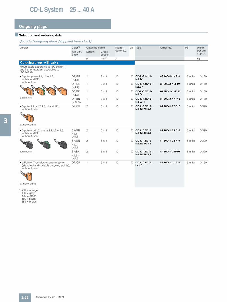
Outgoing plugs
3/26 Siemens LV 70 · 2009
3
Selection and ordering data
Uncoded outgoing plugs (supplied from stock)
1) OR = orange GR = gray GN = green BK = black BN = brown
Version Color1)
Top part/ Base
Outgoing cable Rated current Ie
DT Type Order No. PS* Weight per unit approx.
Length Cross-section
m mm2 A kg
Outgoing plugs with cable
FROR cable according to IEC 60754-1 and flame-retardant according to IEC 60332-1
• 3-pole, phase L1, L2 or L3, with N and PE; without fuse
OR/GR(N/L1)
1 3 × 1 10 X CD-L-A3O10-N/L1-1
8PS0044-1KF10 5 units 0.150
OR/GN(N/L2)
1 3 × 1 10 X CD-L-A3O10-N/L2-1
8PS0044-1LF10 5 units 0.150
OR/BK(N/L3)
1 3 × 1 10 X CD-L-A3O10-N/L3-1
8PS0044-1MF10 5 units 0.150
OR/BN(N2/L3)
1 3 × 1 10 X CD-L-A3O10-N2/L3-1
8PS0044-1NF10 5 units 0.150
• 5-pole, L1 or L2, L3, N and PE; without fuses
OR/OR 2 5 × 1 10 X CD-L-A5O10-N/L1/L2/L3-2
8PS0044-2QF10 5 units 0.320
• 3-pole + L4/L5, phase L1, L2 or L3, with N and PE; without fuses
BK/GRN/L1 + L4/L5
2 5 × 1 10 X CD-L-A5O10-N/L1/L4/L5-2
8PS0044-2RF10 5 units 0.320
BK/GN
N/L2 + L4/L5
2 5 × 1 10 X CD-L-A5O10-N/L2/L4/L5-2
8PS0044-2SF10 5 units 0.320
BK/BK
N/L3 + L4/L5
2 5 × 1 10 X CD-L-A5O10-N/L3/L4/L5-2
8PS0044-2TF10 5 units 0.320
• L4/L5 for 7-conductor busbar system (standard and codable outgoing points), without fuses
OR/OR 1 3 × 1 10 X CD-L-A3O10-L4/L5-1
8PS0044-1UF10 5 units 0.150
G_NSV0_01583
G_NSV0_01584
G_NSV0_01585
G_NSV0_01586
LV70_03.book Seite 26 Mittwoch, 24. September 2008 4:55 16
CD-L System — 25 ... 40 A
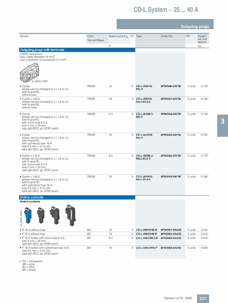
Outgoing plugs
3/27Siemens LV 70 · 2009
3
1) TR = transparent GR = gray BU = blue BK = black
Version Color
Top part/Base
Rated current Ie DT Type Order No. PS* Weight per unit approx.
A kg
Outgoing plugs with terminals
L/N/PE connection: max. cable diameter 14 mm2, max. conductor cross-section 2.5 mm2
• 3-pole, phase can be changed to L1, L2 or L3, with N and PE; without fuse
TR/GR 16 X CD-L-A3O16-N/L-0
8PS0040-0AF16 5 units 0.130
• 3-pole + L4/L5, phase can be changed to L1, L2 or L3, with N and PE; without fuse
TR/GR 16 X CD-L-A5O16-N/L/L4/L5-0
8PS0041-0AF16 5 units 0.150
• 3-pole, phase can be changed to L1, L2 or L3, with N and PE; with micro-fuse 6.3 A, size 5 mm × 20 mm, type gG (IEC), gL (VDE) quick
TR/GR 6.3 X CD-L-A3M6,3-N/L-0
8PS0042-0AF10 5 units 0.140
• 3-pole, phase can be changed to L1, L2 or L3, with N and PE; with cylindrical fuse 16 A, size 8.5 mm × 31.5 mm, type gG (IEC), gL (VDE) quick
TR/GR 16 X CD-L-A3M16-N/L-0
8PS0042-0AF16 5 units 0.150
• 3-pole + L4/L5, phase can be changed to L1, L2 or L3, with N and PE; with micro-fuse 6.3 A, size 5 mm × 20 mm, type gG (IEC), gL (VDE) quick
TR/GR 6.3 X CD-L-A5M6,3-N/L/L4/L5-0
8PS0043-0AF10 5 units 0.170
• 3-pole + L4/L5, phase can be changed to L1, L2 or L3, with N and PE; with cylindrical fuse 16 A, size 8.5 mm × 31.5 mm, type gG (IEC), gL (VDE) quick
TR/GR 16 X CD-L-A5M16-N/L/L4/L5-0
8PS0043-0AF16 5 units 0.190
Mobile contacts
Mobile contacts
• N 16 A without fuse BU 16 X CD-L-AMCO16-N 8PS0081-0AA16 5 units 0.010
• P 16 A without fuse BK 16 X CD-L-AMCO16-P 8PS0082-0AA16 5 units 0.010
• P 10-A holder with micro-fuse 6.3 A, size 5 mm × 20 mm, type gG (IEC), gL (VDE) quick
BK 6.3 X CD-L-AMCM6,3-P 8PS0083-0AA10 5 units 0.010
• P 16-A holder with cylindrical fuse 16 A, size 8.5 mm × 31.5 mm, type gG (IEC), gL (VDE) quick
BK 16 X CD-L-AMCM16-P 8PS0084-0AA16 5 units 0.020
G_NSV0_01587
G_N
SV
0_01
623
LV70_03.book Seite 27 Mittwoch, 24. September 2008 4:55 16

CD-L System — 25 ... 40 A
Outgoing plugs
3/28 Siemens LV 70 · 2009
3
Coded outgoing plugs (delivery on request)
1) RD = red GR = gray GN = green BK = black BN = brown WH = white
Version Color1)
Top part/ Base
Outgoing cable Rated current Ie
DT Type Order No. PS* Weight per unit approx.
Length Cross-section
m mm2 A kg
Outgoing plugs with cable
FROR cable according to IEC 60754-1 and flame-retardant according to IEC 60332-1
For red coded outgoing points
• 3-pole, phase L1, L2 or L3, with N and PE; without fuse
RD/GR(N/L1)
1 3 × 1 10 X CD-L-A3O10-N/L1-1-KR
8PS0054-1KF10 5 units 0.210
RD/GN(N/L2)
1 3 × 1 10 X CD-L-A3O10-N/L2-1-KR
8PS0054-1LF10 5 units 0.210
RD/BK(N/L3)
1 3 × 1 10 X CD-L-A3O10-N/L3-1-KR
8PS0054-1MF10 5 units 0.210
RD/BN(N2/L3)
1 3 × 1 10 X CD-L-A3O10-N2/L3-1-KR
8PS0054-1NF10 5 units 0.210
For white coded outgoing points
• 3-pole, phase L1, L2 or L3, with N and PE; without fuse
WH/GR(N/L1)
1 3 × 1 10 X CD-L-A3O10-N/L1-1-KW
8PS0064-1KF10 5 units 0.210
WH/GN(N/L2)
1 3 × 1 10 X CD-L-A3O10-N/L2-1-KW
8PS0064-1LF10 5 units 0.210
WH/BK(N/L3)
1 3 × 1 10 X CD-L-A3O10-N/L3-1-KW
8PS0064-1MF10 5 units 0.210
WH/BN(N2/L3)
1 3 × 1 10 X CD-L-A3O10-N2/L3-1-KW
8PS0064-1NF10 5 units 0.210
G_NSV0_01588
G_NSV0_01589
LV70_03.book Seite 28 Mittwoch, 24. September 2008 4:55 16

CD-L System — 25 ... 40 A
Outgoing plugs
3/29Siemens LV 70 · 2009
3
1) TR = transparent RD = red WH = white
Version Color
Top part/ Base
Rated current Ie DT Type Order No. PS* Weight per unit approx.
A kg
Outgoing plugs with terminals
L/N/PE connection: max. cable diameter 14 mm2, max. conductor cross-section 2.5 mm2
For red coded outgoing points
• 3-pole, phase can be changed to L1, L2 or L3, with N and PE; without fuse
TR/RD 16 X CD-L-A3O16-N/L-KR-0
8PS0050-0AF16 5 units 0.130
• 3-pole + L4/L5, phase can be changed to L1, L2 or L3, with N and PE; without fuse
TR/RD 16 X CD-L-A5O16-N/L/L4/L5-KR-0
8PS0051-0AF16 5 units 0.150
• 3-pole, phase can be changed to L1, L2 or L3, with N and PE; with cylindrical fuse 16 A, size 8.5 mm × 31.5 mm, type gG (IEC), gL (VDE) quick
TR/RD 16 X CD-L-A3M16-N/L-KR-0
8PS0052-0AF16 5 units 0.150
• 3-pole + L4/L5, phase can be changed to L1, L2 or L3, with N and PE; with cylindrical fuse 16 A, size 8.5 mm × 31.5 mm, type gG (IEC), gL (VDE) quick
TR/RD 16 X CD-L-A5M16-N/L/L4/L5-KR-0
8PS0053-0AF16 5 units 0.190
For white coded outgoing points
• 3-pole, phase can be changed to L1, L2 or L3, with N and PE; without fuse
TR/WH 16 X CD-L-A3O16-N/L-KW-0
8PS0065-0AF16 5 units 0.130
• 3-pole + L4/L5, phase can be changed to L1, L2 or L3, with N and PE; without fuse
TR/WH 16 X CD-L-A5O16-N/L/L4/L5-KW-0
8PS0067-0AF16 5 units 0.150
• 3-pole, phase can be changed to L1, L2 or L3, with N and PE; with cylindrical fuse 16 A, size 8.5 mm × 31.5 mm, type gG (IEC), gL (VDE) quick
TR/WH 16 X CD-L-A3M16-N/L-KW-0
8PS0066-0AF16 5 units 0.150
• 3-pole + L4/L5, phase can be changed to L1, L2 or L3, with N and PE; with cylindrical fuse 16 A, size 8.5 mm × 31.5 mm, type gG (IEC), gL (VDE) quick
TR/WH 16 X CD-L-A5M16-N/L/L4/L5-KW-0
8PS0068-0AF16 5 units 0.190
G_NSV0_01590
G_NSV0_01624
LV70_03.book Seite 29 Mittwoch, 24. September 2008 4:55 16
CD-L System — 25 ... 40 A
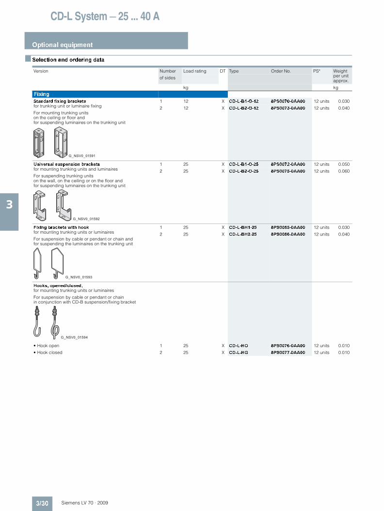
Optional equipment
3/30 Siemens LV 70 · 2009
3
Selection and ordering data
Version Number
of sides
Load rating DT Type Order No. PS* Weight per unit approx.
kg kg
Fixing
Standard fixing brackets for trunking unit or luminaire fixing
For mounting trunking units on the ceiling or floor and for suspending luminaires on the trunking unit
1 12 X CD-L-B1-G-12 8PS0070-0AA00 12 units 0.030
2 12 X CD-L-B2-G-12 8PS0073-0AA00 12 units 0.040
Universal suspension brackets for mounting trunking units and luminaires
For suspending trunking units on the wall, on the ceiling or on the floor and for suspending luminaires on the trunking unit
1 25 X CD-L-B1-O-25 8PS0072-0AA00 12 units 0.050
2 25 X CD-L-B2-O-25 8PS0075-0AA00 12 units 0.060
Fixing brackets with hook for mounting trunking units or luminaires
For suspension by cable or pendant or chain and for suspending the luminaires on the trunking unit
1 25 X CD-L-BH1-25 8PS0085-0AA00 12 units 0.030
2 25 X CD-L-BH2-25 8PS0086-0AA00 12 units 0.040
Hooks, opened/closed, for mounting trunking units or luminaires
For suspension by cable or pendant or chain in conjunction with CD-B suspension/fixing bracket
• Hook open 1 25 X CD-L-HO 8PS0076-0AA00 12 units 0.010
• Hook closed 2 25 X CD-L-HG 8PS0077-0AA00 12 units 0.010
G_NSV0_01591
G_NSV0_01592
G_NSV0_01593
G_NSV0_01594
LV70_03.book Seite 30 Mittwoch, 24. September 2008 4:55 16

CD-L System — 25 ... 40 A
Optional equipment
3/31Siemens LV 70 · 2009
3
Version DT Type Order No. PS* Weight per unit approx.
kg
Cable ducts
Cable ducts made of plastic (white), standard length 3 m.
Cable duct used for cables in auxiliary circuits.
It is mounted on the trunking unit with the fixing brackets for cable ducts (two brackets every 3 m).
X CD-L-CC 8PS0087-0AA00 6 units 0.025
Fixing brackets for cable ducts for mounting the cable ducts on the ceiling, on the floor or on the wall, alone or in combination with trunking units
It can be mounted on the standard fixing brackets or universal suspension brackets.
X CD-L-BCCO 8PS0088-0AA00 12 units 0.040
Optional equipment for degree of protection IP55
IP55 covers for outgoing point X CD-L-FAS 8PS0080-0AA00 12 units 0.010
G_NSV0_01595
G_NSV0_01596
G_NSV0_01597
LV70_03.book Seite 31 Mittwoch, 24. September 2008 4:55 16

CD-L System — 25 ... 40 A
Configuration information
3/32 Siemens LV 70 · 2009
3
Overview
Specimen text for tenders
Item Quantity Description Unit price Amount
... m Busbar trunking system for small loads and lighting installations
• As type-tested low-voltage switchgear and controlgear combination (TTA) according to IEC/EN 60439-1 and -2
• Rated current ... A, corresponds to thermal rated current ... A at max. +40 °C and +35 °C on a 24 h average for indoor installation
• Rated insulation voltage Ui = 690 V AC; overvoltage category/degree of pollution III/3
• Operational voltage ... V, ... Hz
• Rated peak withstand current of busbar trunking system,... kA tested according to IEC/EN 60439-1
• Degree of protection IP55
• 3-, 5-, 7- , 2 × 3, 1 × 5- + 1 × 3-, 2 × 5, 2 × 7-conductor system
• Copper conductor, insulated along its whole length
• Trunking units, sheet steel enclosed, unpainted/painted finish
• Halogen-free
• Outgoing points at 0.5 m, 1 m or 1.5 m intervals per side
• Supplied ready for connection with all assembly parts
• Made by Siemens
• Type CD-L-...
Comprising:
LV70_03.book Seite 32 Mittwoch, 24. September 2008 4:55 16
CD-L System — 25 ... 40 A
Configuration information
3/33Siemens LV 70 · 2009
3
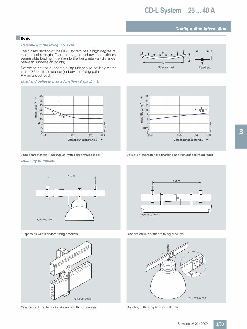
Design
Determining the fixing intervals
The closed section of the CD-L system has a high degree of mechanical strength. The load diagrams show the maximum permissible loading in relation to the fixing interval (distance between suspension points).
Deflection f of the busbar trunking unit should not be greater than 1/350 of the distance (L) between fixing points. F = balanced load.
Load and deflection as a function of spacing L
Load characteristic (trunking unit with concentrated load) Deflection characteristic (trunking unit with concentrated load)
Mounting examples
Suspension with standard fixing brackets
Mounting with cable duct and standard fixing brackets
Suspension with standard fixing brackets
Mounting with fixing bracket with hook
NS
V0_
0001
8L
f
L
F
Streckenlast Punktlast
Befestigungsabstand L
max
. Las
t P
2,0
303540
252015
(kg)
50
2,5 (m) 3,0
NS
V0_
0163
7
f/L = 1/350
Befestigungsabstand Lm
ax. B
iegu
ng f 12
1614
10864
0 NS
V0_
0163
8
f = 1 · L 350
2,0 2,5 (m) 3,0
(mm)
G_NSV0_01633
≤ 3 m
≤ 3 m
G_NSV0_01634
LV70_03.book Seite 33 Mittwoch, 24. September 2008 4:55 16

CD-L System — 25 ... 40 A
Configuration information
3/34 Siemens LV 70 · 2009
3
Arrangement of luminaires
The numbers, e.g. , indicate the corresponding position of the luminaires in the table below.
Single lamp
= Single lamp, non-compensated, p.f. = 0.5
= Single lamp, parallel-compensated, p.f. = 0.9
= Single lamp, alternately series-compensated, p.f. = 0.1
Two lamps
= Two lamps, non-compensated
= Two lamps, duo circuit, p.f. = 1
Three lamps
= Three lamps, alternately series-compensated
= Three lamps, non-compensated
X X X
L1L2L3N
NS
V0_
0002
5
X X X
L1
L2L3
N
NS
V0_
0002
6
X X X
L1L2L3N
X X X
NSV0_00027
X
X
X X
X X
L1L2L3N
NS
V0_
0002
8N
SV
0_00
029
X
X
X X
X X
L1
L2L3
N
NS
V0_
0003
0
X
X
X
X
X
X
L1L2L3N
NS
V0_
0003
1
X
X
X
L1L2L3N
LV70_03.book Seite 34 Mittwoch, 24. September 2008 4:55 16
CD-L System — 25 ... 40 A
Configuration information
3/35Siemens LV 70 · 2009
3
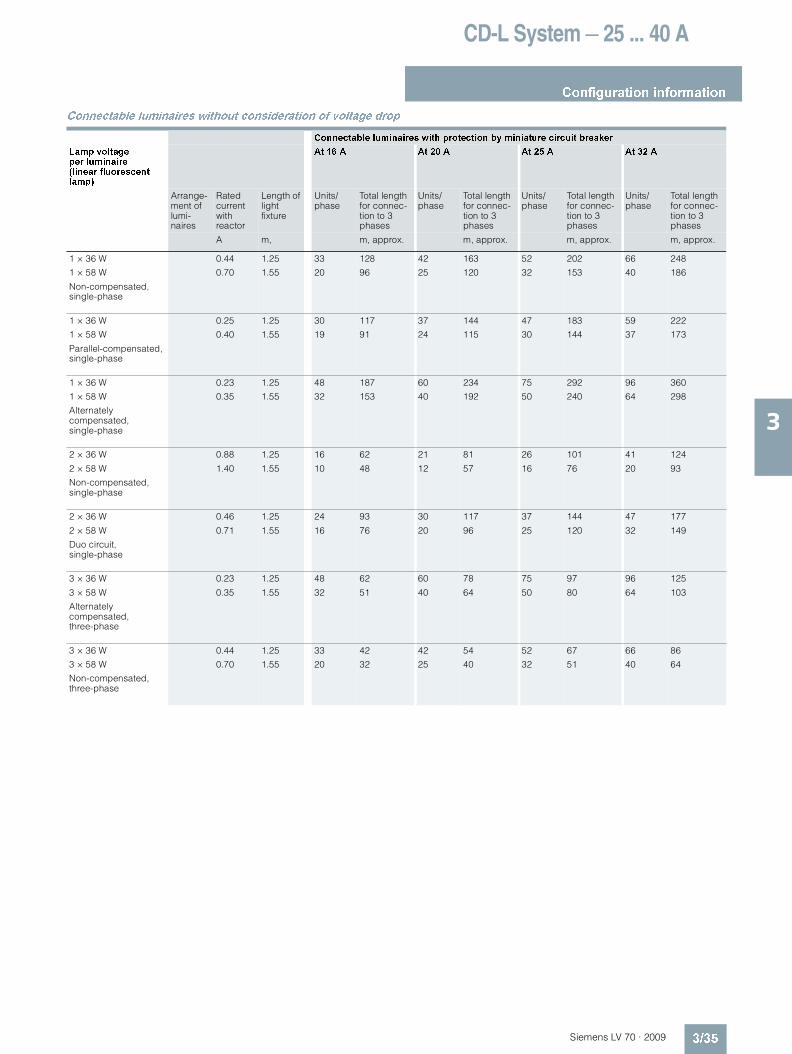
Connectable luminaires without consideration of voltage drop
Connectable luminaires with protection by miniature circuit breaker
Lamp voltage per luminaire(linear fluorescent lamp)
At 16 A At 20 A At 25 A At 32 A
Arrange-ment of lumi-naires
Rated current with reactor
Length of light fixture
Units/phase
Total length for connec-tion to 3 phases
Units/phase
Total length for connec-tion to 3 phases
Units/phase
Total length for connec-tion to 3 phases
Units/phase
Total length for connec-tion to 3 phases
A m, m, approx. m, approx. m, approx. m, approx.
1 × 36 W
1 × 58 W
Non-compensated, single-phase
0.44
0.70
1.25
1.55
33
20
128
96
42
25
163
120
52
32
202
153
66
40
248
186
1 × 36 W
1 × 58 W
Parallel-compensated, single-phase
0.25
0.40
1.25
1.55
30
19
117
91
37
24
144
115
47
30
183
144
59
37
222
173
1 × 36 W
1 × 58 W
Alternately compensated, single-phase
0.23
0.35
1.25
1.55
48
32
187
153
60
40
234
192
75
50
292
240
96
64
360
298
2 × 36 W
2 × 58 W
Non-compensated, single-phase
0.88
1.40
1.25
1.55
16
10
62
48
21
12
81
57
26
16
101
76
41
20
124
93
2 × 36 W
2 × 58 W
Duo circuit, single-phase
0.46
0.71
1.25
1.55
24
16
93
76
30
20
117
96
37
25
144
120
47
32
177
149
3 × 36 W
3 × 58 W
Alternately compensated, three-phase
0.23
0.35
1.25
1.55
48
32
62
51
60
40
78
64
75
50
97
80
96
64
125
103
3 × 36 W
3 × 58 W
Non-compensated, three-phase
0.44
0.70
1.25
1.55
33
20
42
32
42
25
54
40
52
32
67
51
66
40
86
64
LV70_03.book Seite 35 Mittwoch, 24. September 2008 4:55 16

CD-L System — 25 ... 40 A
Configuration information
3/36 Siemens LV 70 · 2009
3
Connectable luminaires with protection by gL melting fuses
Lamp voltage per luminaire(linear fluorescent lamp)
At 16 A At 20 A At 25 A At 35 A
Arrange-ment of lumi-naires
Rated current with reactor
Length of light fixture
Units/phase
Total length for connec-tion to 3 phases
Units/phase
Total length for connec-tion to 3 phases
Units/phase
Total length for connec-tion to 3 phases
Units/phase
Total length for connec-tion to 3 phases
A m, m, approx. m, approx. m, approx. m, approx.
1 × 36 W
1 × 58 W
Non-compensated, single-phase
0.44
0.70
1.25
1.55
33
20
128
96
42
25
163
120
52
32
202
153
72
44
280
211
1 × 36 W
1 × 58 W
Parallel-compensated, single-phase
0.25
0.40
1.25
1.55
36
23
140
110
44
28
171
134
60
38
234
182
90
56
351
268
1 × 36 W
1 × 58 W
Alternately compensated, single-phase
0.23
0.35
1.25
1.55
48
32
187
153
60
40
234
192
75
50
292
240
105
70
409
336
2 × 36 W
2 × 58 W
Non-compensated, single-phase
0.88
1.40
1.25
1.55
16
10
62
48
21
12
81
57
26
16
101
76
36
22
140
105
2 × 36 W
2 × 58 W
Duo circuit, single-phase
0.46
0.71
1.25
1.55
24
16
93
76
30
20
117
96
37
25
144
120
51
35
198
168
3 × 36 W
3 × 58 W
Alternately compensated, three-phase
0.23
0.35
1.25
1.55
48
32
62
51
60
40
78
64
75
50
97
80
105
70
136
112
3 × 36 W
3 × 58 W
Non-compensated, three-phase
0.44
0.70
1.25
1.55
33
20
42
32
42
25
54
40
52
32
67
51
72
44
93
64
LV70_03.book Seite 36 Mittwoch, 24. September 2008 4:55 16

CD-L System — 25 ... 40 A
Configuration information
3/37Siemens LV 70 · 2009
3
Function
Short-circuit protection
The lengths of the busbar lines given in the guide value tables on pages 3/35 and 3/36 take into account only the rated current of the connectable luminaires.
To determine the precise length of the busbar line, voltage drops and short-circuit protection must be taken into account.
Voltage drop ΔU
According to the technical literature, the voltage drop should lie between 3 % and 5 % when the load is evenly split in light networks.
With ΔU (V) according to page 3/38
Fault protection according to DIN VDE 0100 Part 410
Calculation of the current resulting in automatic interruption, taking into account the incoming supply cable and the outgoing unit.
with
For example:
Provided that the protective device is positioned immediately upstream of the busbar line, ZInc can be ignored.
The admissible opening delay is as specified in DIN VDE 0100 Part 430:
with
The total break time of the selected protective device must not exceed the determined admissible opening delay and must not be greater than 5 s.
SchutzorganZuleitung CD-System
Leuchte
Abgang mit Leitung1mm bzw. 1,5mm 2 2
Zul Zul CD CD
NS
V0_
0003
2
x
z z
ΔU(%) = ΔU (V)Ue (V)
× 100 %
Ia = Uo
Zs= Uo
ZSource + ZInc + ZCD + ZOut
Uo
ZSource + ZInc ×lInc + ZCD ×lCD + ZOut =(A) (A)
Ia = Current resulting in automatic interruption (A)
Uo = Voltages to earth (V)
Zs = Fault loop impedance. Can be measured, calculated or determined using the network model.
(Ω)
ZSource = Source impedance (Ω)
lInc = Single length of incoming supply cable (m)
lCD = Single length of CD system (m)
lOut = Length of outgoing unit (m)
ZInc = Loop impedance of incoming supply cable (Ω/m)
ZCD = Loop impedance of CD system (Ω/m)
ZOut = Loop impedance of outgoing unit (Ω/m)
ZInc = 22 × 10-3 Ω/m at 2.5 mm2
ZCD = 4.241 × 10⁻³ Ω/m at CD-L 25 A0.833 × 10-3 Ω/m at CD-L 40 A
ZOut = 54 × 10-3 Ω/m at 1 mm2
36 × 10-3 Ω/m at 1,5 mm2
t = Admissible opening delay (s)
S = Smallest conductor cross-section to be pro-tected (outgoing unit) 1 mm2 or 1.5 mm2
(mm2)
Ia = Current according to above calculation (A)
t = SIa
(s)(115 × )2
LV70_03.book Seite 37 Mittwoch, 24. September 2008 4:55 16
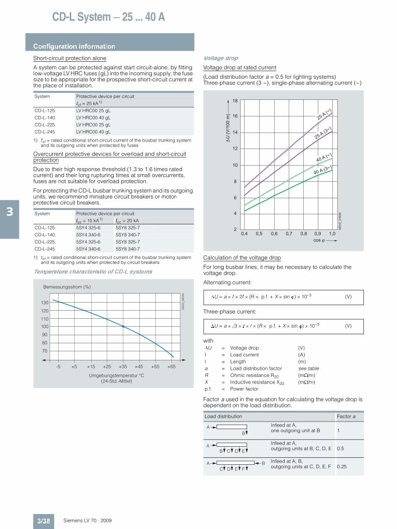
CD-L System — 25 ... 40 A
Configuration information
3/38 Siemens LV 70 · 2009
3
Short-circuit protection alone
A system can be protected against start circuit-alone, by fitting low-voltage LV HRC fuses (gL) into the incoming supply; the fuse size to be appropriate for the prospective short-circuit current at the place of installation.
1) Icf = rated conditional short-circuit current of the busbar trunking system and its outgoing units when protected by fuses
Overcurrent protective devices for overload and short-circuitprotection
Due to their high response threshold (1.3 to 1.6 times rated current) and their long rupturing times at small overcurrents, fuses are not suitable for overload protection.
For protecting the CD-L busbar trunking system and its outgoing units, we recommend miniature circuit breakers or motor-protective circuit breakers.
1) Icf = rated conditional short-circuit current of the busbar trunking system and its outgoing units when protected by circuit breakers
Temperature characteristic of CD-L systems
Voltage drop
Voltage drop at rated current
(Load distribution factor a = 0.5 for lighting systems) Three-phase current (3 ~), single-phase alternating current (~)
Calculation of the voltage drop
For long busbar lines, it may be necessary to calculate the voltage drop.
Alternating current:
Three-phase current:
with
Factor a used in the equation for calculating the voltage drop is dependent on the load distribution.
System Protective device per circuit
Icf = 25 kA1)
CD-L-125. LV HRC00 25 gL
CD-L-140. LV HRC00 40 gL
CD-L-225. LV HRC00 25 gL
CD-L-245 LV HRC00 40 gL
System Protective device per circuit
Icc = 15 kA1)Icc = 20 kA
CD-L-125. 5SY4 325-6 5SY8 325-7
CD-L-140. 5SY4 340-6 5SY8 340-7
CD-L-225. 5SY4 325-6 5SY8 325-7
CD-L-245 5SY4 340-6 5SY8 340-7
Bemessungsstrom (%)
Umgebungstemperatur °C(24-Std.-Mittel)
NS
V0_
0003
4
-5
130
120
110
100
90
80
70
+5 +15 +25 +35 +45 +55 +65
ΔU = Voltage drop (V)I = Load current (A)l = Length (m)a = Load distribution factor see tableR = Ohmic resistance R20 (mΩ/m)X = Inductive resistance X20 (mΩ/m)p.f. = Power factor
Load distribution Factor a
Infeed at A, one outgoing unit at B 1
Infeed at A, outgoing units at B, C, D, E 0.5
Infeed at A, B, outgoing units at C, D, E, F 0.25
(V/1
00 m
)U
18
16
14
12
10
8
6
4
2 NS
V0_
0163
9
25 A (~)
25 A (3~)
40 A (~)
40 A (3~)
0,4 0,5 0,6 0,7 0,8 0,9 1,0cos
ΔU = a × I × 2l × (R × p.f. + X × sin ϕ) × 10–3 (V)
ΔU = a × �3 × I × l × (R × p.f. + X × sin ϕ) × 10–3 (V)
AB
AEDCB
FEDCA B
LV70_03.book Seite 38 Mittwoch, 24. September 2008 4:55 16
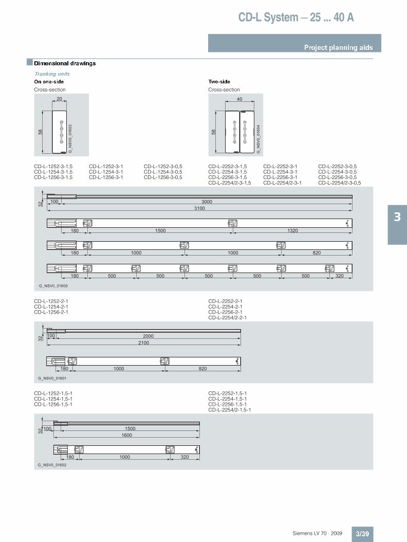
CD-L System — 25 ... 40 A
Project planning aids
3/39Siemens LV 70 · 2009
3
Dimensional drawings
Trunking units
On one-side Two-side
Cross-section Cross-section
CD-L-1252-3-1,5CD-L-1254-3-1,5CD-L-1256-3-1,5
CD-L-1252-3-1CD-L-1254-3-1CD-L-1256-3-1
CD-L-1252-3-0,5CD-L-1254-3-0,5CD-L-1256-3-0,5
CD-L-2252-3-1,5CD-L-2254-3-1,5CD-L-2256-3-1,5CD-L-2254/2-3-1,5
CD-L-2252-3-1CD-L-2254-3-1CD-L-2256-3-1CD-L-2254/2-3-1
CD-L-2252-3-0,5CD-L-2254-3-0,5CD-L-2256-3-0,5CD-L-2254/2-3-0,5
CD-L-1252-2-1CD-L-1254-2-1CD-L-1256-2-1
CD-L-2252-2-1CD-L-2254-2-1CD-L-2256-2-1CD-L-2254/2-2-1
CD-L-1252-1,5-1CD-L-1254-1,5-1CD-L-1256-1,5-1
CD-L-2252-1,5-1CD-L-2254-1,5-1CD-L-2256-1,5-1CD-L-2254/2-1,5-1
G_N
SV
0_01
603
20
58
G_N
SV
0_01
604
40
58
G_NSV0_01600
8201000 1000180
320500 500 500 500500180
13201500180
100 3000310032
8201000180
100 2000210032
G_NSV0_01601
G_NSV0_01602
3201000180
100 1500160032
LV70_03.book Seite 39 Mittwoch, 24. September 2008 4:55 16
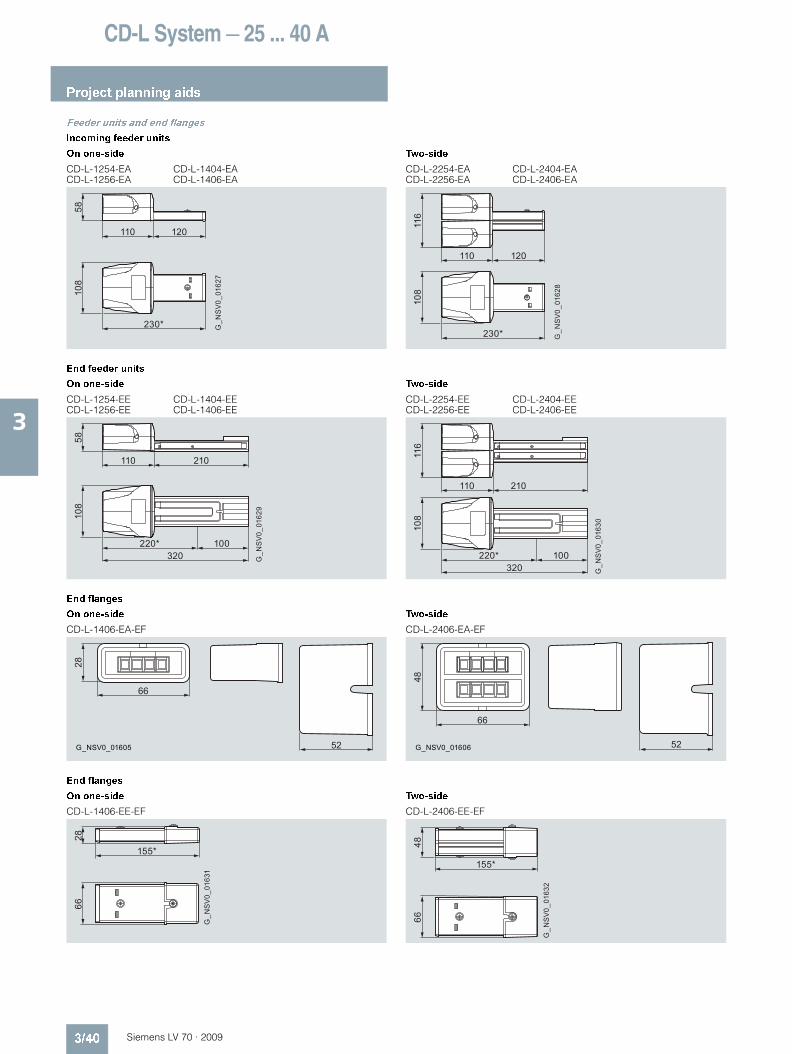
CD-L System — 25 ... 40 A
Project planning aids
3/40 Siemens LV 70 · 2009
3
Feeder units and end flanges
Incoming feeder units
On one-side Two-side
CD-L-1254-EACD-L-1256-EA
CD-L-1404-EACD-L-1406-EA
CD-L-2254-EACD-L-2256-EA
CD-L-2404-EACD-L-2406-EA
End feeder units
On one-side Two-side
CD-L-1254-EECD-L-1256-EE
CD-L-1404-EECD-L-1406-EE
CD-L-2254-EECD-L-2256-EE
CD-L-2404-EECD-L-2406-EE
End flanges
On one-side Two-side
CD-L-1406-EA-EF CD-L-2406-EA-EF
End flanges
On one-side Two-side
CD-L-1406-EE-EF CD-L-2406-EE-EF
G_N
SV
0_01
627
110
230*
5810
8
120
G_N
SV
0_01
628
110
230*
116
108
120G
_NS
V0_
0162
9
110
320
5810
8
210
220* 100
G_N
SV
0_01
630
110
320
116
108
210
220* 100
52
66
28
G_NSV0_01605 G_NSV0_01606 52
66
48
G_N
SV
0_01
631
2866
155*
G_N
SV
0_01
632
4866
155*
LV70_03.book Seite 40 Mittwoch, 24. September 2008 4:55 16
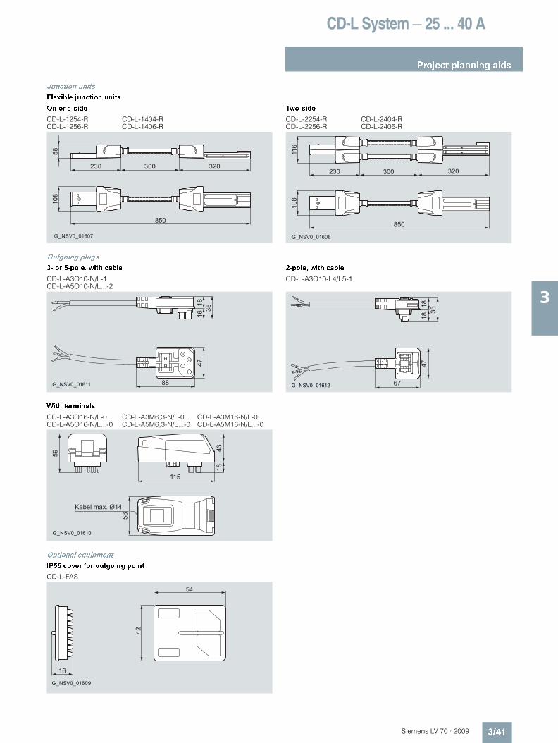
CD-L System — 25 ... 40 A
Project planning aids
3/41Siemens LV 70 · 2009
3
Junction units
Flexible junction units
On one-side Two-side
CD-L-1254-RCD-L-1256-R
CD-L-1404-RCD-L-1406-R
CD-L-2254-RCD-L-2256-R
CD-L-2404-RCD-L-2406-R
Outgoing plugs
3- or 5-pole, with cable 2-pole, with cable
CD-L-A3O10-N/L-1CD-L-A5O10-N/L...-2
CD-L-A3O10-L4/L5-1
With terminals
CD-L-A3O16-N/L-0CD-L-A5O16-N/L...-0
CD-L-A3M6,3-N/L-0CD-L-A5M6,3-N/L...-0
CD-L-A3M16-N/L-0CD-L-A5M16-N/L...-0
Optional equipment
IP55 cover for outgoing point
CD-L-FAS
G_NSV0_01607
230
108
58
850
320300
G_NSV0_01608
230
108
116
320300
850
N
L1
G_NSV0_01611
3516
1847
88 G_NSV0_01612 67
4718
3618
Kabel max. Ø14
G_NSV0_01610
58
43
115
59
16
G_NSV0_01609
16
42
54
LV70_03.book Seite 41 Mittwoch, 24. September 2008 4:55 16
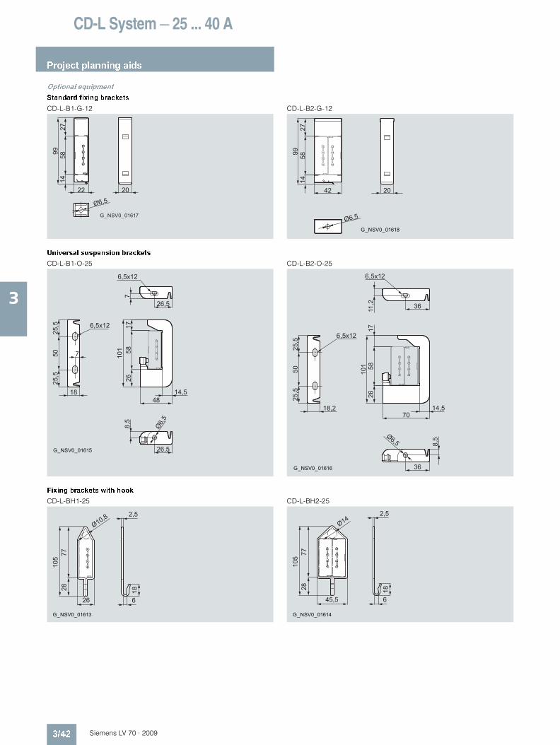
CD-L System — 25 ... 40 A
Project planning aids
3/42 Siemens LV 70 · 2009
3
Optional equipment
Standard fixing brackets
CD-L-B1-G-12 CD-L-B2-G-12
Universal suspension brackets
CD-L-B1-O-25 CD-L-B2-O-25
Fixing brackets with hook
CD-L-BH1-25 CD-L-BH2-25
Ø6,5
G_NSV0_01617
20
9914
5827
22
Ø6,5
G_NSV0_01618
1458
2799
42 20
25,5
25,5
6,5x12
6,5x12
26,5
14,5
26,5
8,5
Ø6,5
G_NSV0_01615
50
18
7
710
1 5817
26
48
11,2
8,5Ø6,5
25,5
25,5
18,2 14,5
G_NSV0_01616
36
36
50 101
26
70
5817
2,5
Ø10,8
18
626
2877
105
G_NSV0_01613 G_NSV0_01614
18
6
2,5Ø14
45,5
2877
105
LV70_03.book Seite 42 Mittwoch, 24. September 2008 4:55 16
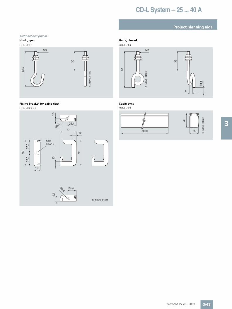
CD-L System — 25 ... 40 A
Project planning aids
3/43Siemens LV 70 · 2009
3
Optional equipment
Hook, open Hook, closed
CD-L-HO CD-L-HG
Fixing bracket for cable duct Cable duct
CD-L-BCCO CD-L-CC
35
M5
63,7
G_N
SV
0_01
619
15,2
G_N
SV
0_01
620
5
35
M5
65
Ø6,526,4
8,5
37,5
37,5
Ø6,5
9,7
26,4
hole
13
75
1247
6,5x12
18
75
G_NSV0_01621G
_NS
V0_
0162
2
40
253000
LV70_03.book Seite 43 Mittwoch, 24. September 2008 4:55 16

CD-L System — 25 ... 40 A
Notes
3/44 Siemens LV 70 · 2009
3
LV70_03.book Seite 44 Mittwoch, 24. September 2008 4:55 16
The information provided in this catalog contains descriptions or characteristics of performance which in case of actual use do not always apply as described or which may change as a result of further development of the products. An obligation to provide the respective characteristics shall only exist if expressly agreed in the terms of contract. Availability and technical specifications are subject to change without notice. All product designations may be trademarks or product names of Siemens AG or supplier companies whose use by third parties for their own purposes could violate the rights of the owners.
Siemens Industrial Automation & Drive Technologies Sir William Siemens House Princess Road Manchester M20 2UR Tel 0161 446 6400 Fax 0161 446 5789 www.siemens.co.uk/busbars