cd22 series · cd22-35 cd22m-15 cd22-100 cd22m-100 - thank you for purchasing cd22 series. we hope...
TRANSCRIPT

■ NPN type
Instruction manual
Precautions for using laser● Regulations in the USAWhen exporting laser devices to the USA, the USA laser control, FDA(Food and Drug Administration) is applied. This product has been alreadyreported to CDRH (Center for Devices and Radiological Health). Fordetails, contact our customer service.
Bundled goods in the boxPlease confirm following goods bundled in the box.
・CD22□-□□□□ ・This instruction manual
● The light source of this product applies the visible light semiconductor laser. Do not allow the laser beam to enter an eye, either directly or reflected from reflective object. If the laser beam enters an eye, it may cause blindness.
● This product is not an explosion proof construction. Do not use the product under flam-mable , explosive gas or liquid environment.
● Do not disassemble or modify the product since it is not designed to automatically stop the laser emission when open. Disassembling or modifying at customer's end it may cause personal injury, fire or electric shock.
●Use of controls or adjustments or performance of procedures other than those specified herein may result in hazardous radiation exposure.
● It is dangerous to wire or attach/remove the connector while the power is on. Make sure to turn off the power before operation.
● Installing in the following places may result in malfunction: 1. A dusty or steamy place 2. A place generating corrosive gas 3. A place directly receiving scattering water or oil. 4. A place suffered from heavy vibration or impact.
● The product is not designed for outdoor use.
● Do not use the sensor in a transient state at power on (Approx. 15min. Warm up period)
● Do not wire with the high voltage cable or the power lines. Failure to do this will cause malfunction by induction or damage.
● Do not use the product in water.
● Operate within the rated range.
● Wipe off dirt on the emitting/receiving parts to maintain correct detection. Also, avoid direct impact on the product.
Warning Mandatory Requirements
Warning Safety Precautions
Indicates a possible hazard that may result in death, serious injury, WARNINGS or serious property damage if the product is used without observing the stated instructions.
CD22SeriesCD22-15□□ CD22M-15□□CD22-35□□ CD22M-15□□CD22-100□□ CD22M-100□□
- Thank you for purchasing CD22 series. We hope you are satisfied with its performance.
- Please read this manual carefully and keep it for future reference.
Displacement sensor
Dimensions
Connection diagram
■ PNP type
■ Pins configuration ( sensor side )
Brown
Gray
Black
Blue
White
■ M12 type
■ M8 type
Display
M12 5pinConnector
Display
M8 4pinConnector
Em
itter
axi
sE
mitt
er a
xis
: 0V / Analog GND
: External input
: Control output*
Mai
n C
ircui
t 3.3V
Brown : +V
: Analog output
* : M8 connector type doesn't have
DC 12~24V ±10%
M12 type M8 typeBrown
Black (None)
Gray Black
White White
Blue Blue
Mai
n C
ircui
t* : M8 connector type doesn't have
DC 12~24V ±10%Brown : +VM12 type M8 typeBrown
: 0V / Analog GND
: Analog outputWhite White
Blue Blue
: : External input
: Control output*Black (None)
Gray Black
Specifications Setup
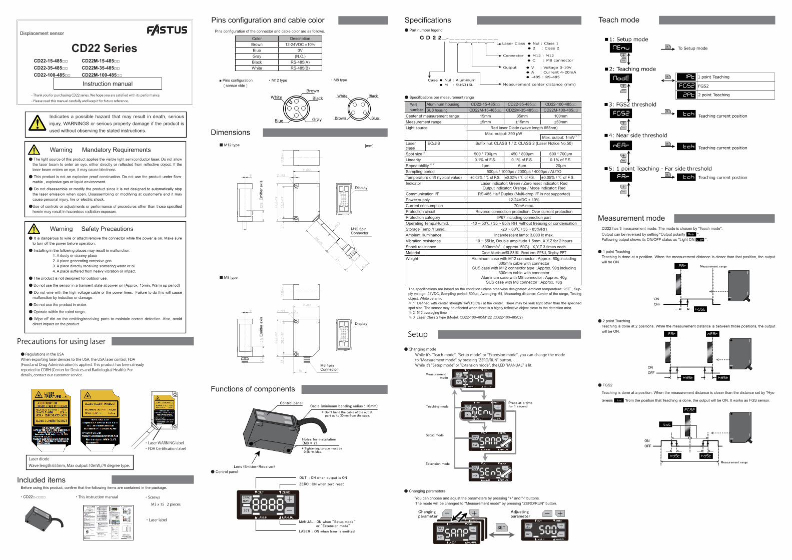
Functions of components
Part number
Aluminum housing CD22-15□□ CD22-35□□ CD22-100□□SUS housing CD22M-15□□ CD22M-35□□ CD22M-100□□
Center of measurement range 15mm 35mm 100mmMeasurement range ±5mm ±15mm ±50mmLight source Red laser Diode (wave length 655nm)
Max. output: 390 µWMax. output: 1mW ※ 3
Laser class
IEC/JIS Suffix nul: CLASS 1 / 2: CLASS 2 (Laser Notice No.50)
Spot size ※ 1 500 * 700µm 450 * 800µm 600 * 700µmLinearity 0.1% of F.S. 0.1% of F.S. 0.1% of F.S.Repeatability ※ 2 1µm 6µm 20µmSampling period 500µs / 1000µs / 2000µs / 4000µs / AUTOTemperature drift (typical value) ±0.02% / ℃ of F.S. ±0.02% / ℃ of F.S. ±0.05% / ℃ of F.S.Indicator Laser indicator: Green / Zero reset indicator: Red
Output indicator: Orange / Mode indicator: RedExternal Input Laser OFF, Teaching, Sample & Hold, One shot, Zero resetControl Output NPN/PNP max.100mA/DC30V ((Residual voltage 1.8 V max.)Current consumption 70mA max. including Analog output currentProtection circuit Reverse connection protection, Over current protectionProtection category IP67 including connection partOperating Temp./Humid. -10 ~ 50℃ / 35 ~ 85% RH without freasing or condensationStorage Temp./Humid. -20 ~ 60℃ / 35 ~ 85%/RHAmbient illuminance Incandescent lamp: 3,000 lx max.Vibration resistence 10 ~ 55Hz, Double amplitude 1.5mm, X,Y,Z for 2 hoursShock resistence 500mm/s2 ( approx. 50G) X,Y,Z 3 times eachMaterial Case: Aluminum/SUS316L, Front lens: PPSU, Display: PETWeight Aluminum case with M12 connector : Approx. 60g including
300mm cable with connectorSUS case with M12 connector type : Approx. 90g including
300mm cable with connectorAluminum case with M8 connector : Approx. 40g
SUS case with M8 connector : Approx. 70g
The specifications are based on the condition unless otherwise designated: Ambient temperature: 23℃ , Sup-ply voltage: 24VDC, Sampling period: 500µs, Averaging: 64, Measuring distance: Center of the range, Testing object: White ceramic※ 1 Defined with center strength 1/e2(13.5%) at the center. There may be leak light other than the specified spot size. The sensor may be affected when there is a highly reflective object close to the detection area.※ 2 512 averaging time※ 3 for Laser Class 2 type ( Model : CD22-100AM122 , CD22-100VM122 , CD22-100A2 , CD22-100V2)
● Specifications per measurement range
● Specifications per output
Part number CD22□-□□V CD22□-□□A CD22□-□□-485Type Voltage output Current output RS-485 typeAnalog output range 0 ~ 10V ※ 1 4 ~ 20mA ーMaximum load impedance ー 300Ω ーOutput impedance 100Ω ー ーPower supply DC12-24V ±10% ※ 1
※ 1 Please keep power supply voltage over 12.0V for Voltage output type to get 0-10V analog output correctly.
● Part number legend
C D 2 2 _- _ _ _ _ _ _ _ _ _
Measurement center distance (mm)
Output
Laser Class
Connector ● M12 : M12● C : M8 connector
● V : Voltage 0-10V● A : Current 4-20mA● -485 : RS-485
● Nul : Class 1● 2 : Class 2
Case ● Nul : Aluminum● M : SUS316L
Control panel
Holes for installation(M3 * 2)
Lens (Emitter/Receiver)
* Tightening torque must be0.5N・m Max.
Cable (minimum bending radius : 10mm)
* Don't bend the cable of the outlet part up to 30mm from the case.
● Control panel
● Changing modeWhile it's "Teach mode", "Setup mode" or "Extension mode", you can change the mode to "Measurement mode" by pressing "ZERO/RUN" button.While it's "Setup mode" or "Extension mode", the LED "MANUAL" is lit.
● Changing parameters
You can choose and adjust the parameters by pressing "+" and "-" buttons.The mode will be changed to "Measurement mode" by pressing "ZERO/RUN" button.
NEnu
NodE
FGS2
nEAr
FAr
-
+
-
+
-
+
-
+
1Pt
FGS2
2Pt
SET
SET
1 point Teaching
FGS2
2 point Teaching
tch
SET
tch
SET
tch
Teaching current position
Teaching current position
Teaching current postiion
SET To Setup mode
■1: Setup mode
■2: Teaching mode
■3: FGS2 threshold
■4: Near side threshold
■5: 1 point Teaching - Far side threshold
-
+
Teach mode
OUT : ON when output is ON
ZERO : ON when zero reset
MANUAL : ON when "Setup mode" or "Extension mode"
LASER : ON when laser is emitted
SET
- + - +Changingparameter
Adjustingparameter
Measurement mode
Teaching mode
Setup mode
Extension mode
Press at a timefor 1 second
・Screws
M3 × 15…2
[mm]
・Laser label [reserve]
・ M12 type ・ M8 type
Black
Brown
White
Blue
・Laser WARNING label・FDA Certification label
Laser diodeWave length:655nm, Max output:10mW,//9 degree type.
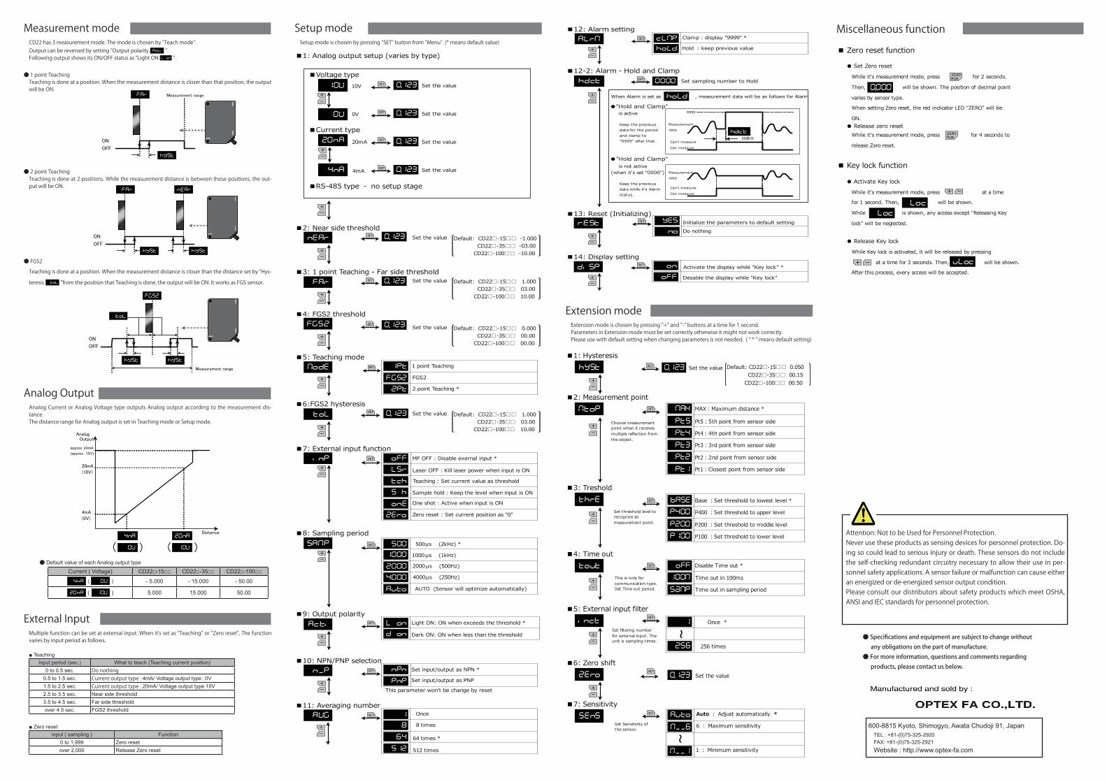
External InputMultiple function can be set at external input. When it's set as "Teaching" or "Zero reset", The function varies by input period as follows.
■ Teachinginput period (sec.) What to teach (Teaching current position)
0 to 0.5 sec. Do nothing0.5 to 1.5 sec. Current output type : 4mA/ Voltage output type : 0V1.5 to 2.5 sec. Current output type : 20mA/ Voltage output type 10V2.5 to 3.5 sec. Near side threshold3.5 to 4.5 sec. Far side thresholdover 4.5 sec. FGS2 threshold
■ Zero resetinput ( sampling ) Function
0 to 1,999 Zero resetover 2,000 Release Zero reset
● Specifications and equipment are subject to change without any obligations on the part of manufacture.● For more information, questions and comments regarding products, please contact us below.
Attention: Not to be Used for Personnel Protection.Never use these products as sensing devices for personnel protection. Do-ing so could lead to serious injury or death. These sensors do not include the self-checking redundant circuitry necessary to allow their use in per-sonnel safety applications. A sensor failure or malfunction can cause either an energized or de-energized sensor output condition.Please consult our distributors about safety products which meet OSHA, ANSI and IEC standards for personnel protection.
600-8815 Kyoto, Shimogyo, Awata Chudoji 91, JapanTEL : +81-(0)75-325-2920FAX: +81-(0)75-325-2921Website : http://www.optex-fa.com
Extension modeExtension mode is chosen by pressing "+" and "-" buttons at a time for 1 second.Parameters in Extension mode must be set correctly otherwise it might not work correctly.Please use with default setting when changing parameters is not needed. ( " * " means default setting)
hYSt
NtoP
thrE
tout
inct
2Ero
SEnS
-
+
-
+
-
+
-
+
-
+
-
+
0.123 Set the valueSET
NAH MAX:Maximum distance *SET
bASE Base :Set threshold to lowest level *SET
SET
SET
0.123 Set the valueSET
SET
Pt5
Pt4
Pt3
Pt2
Pt1
Pt5:5th point from sensor side
Pt4:4th point from sensor side
Pt3:3rd point from sensor side
Pt2:2nd point from sensor side
Pt1:Closest point from sensor side
P400
P200
P100
P400 :Set threshold to upper level
P200 :Set threshold to middle level
P100 :Set threshold to lower level
Choose measurement point when it receives multiple reflection from the object.
Set threshold level to recognize as measurement point.
off Disable Time out *
100N
SaNp
Time out in 100ms
Time out in sampling period
1 Once *
256 256 times
~Set filtering number for external input. Theunit is sampling times.
Auto Auto : Adjust automatically *
N__6
N__1
6 : Maximum sensitivity
1 : Minimum sensitivity
~
Set Sensitivity of the sensor.
This is only for communication type.Set Time out period.
■1: Hysteresis
■2: Measurement point
■3: Treshold
■4: Time out
■5: External input filter
■6: Zero shift
■7: Sensitivity
Default: CD22□-15□□ 0.050 CD22□-35□□ 00.15 CD22□-100□□ 00.50
Measurement modeCD22 has 3 measurement mode. The mode is chosen by "Teach mode".Output can be reversed by setting "Output polarity Acti ".Following output shows its ON/OFF status as "Light ON L on ".
● 1 point TeachingTeaching is done at a position. When the measurement distance is closer than that position, the output will be ON.
● 2 point TeachingTeaching is done at 2 positions. While the measurement distance is between those positions, the out-put will be ON.
● FGS2
Teaching is done at a position. When the measurement distance is closer than the distance set by "Hys-
teresis toL "from the position that Teaching is done, the output will be ON. It works as FGS sensor.
Setup modeSetup mode is chosen by pressing "SET" button from "Menu". (* means default value)
■4: FGS2 threshold
AUG
SANP
1
8-
+
■11: Averaging number
64
-
+
■8: Sampling period500
1000
Once
8 times
64 times *
2000
4000
Auto
500µs (2kHz) *
1000µs (1kHz)
2000µs (500Hz)
4000µs (250Hz)
AUTO (Sensor will optimize automatically)
SET
SET
NodE 1Pt
FGS2-
+
2Pt
SET
■5: Teaching mode1 point Teaching
FGS2
2 point Teaching *
toL 0.123
■6:FGS2 hysteresisSET
10U
0U
20nA
4nA
■Voltage type
■Current type
■RS-485 type - no setup stage
-
+
-
+
10V SET
0V SET
20mA SET
4mASET
0.123 Set the value
0.123 Set the value
0.123 Set the value
0.123 Set the value
■1: Analog output setup (varies by type)
Set the value
-
+
FGS2
FAr
nEAr
-
+
-
+
0.123
0.123
■2: Near side threshold
0.123
■3: 1 point Teaching - Far side threshold
SET
SET
SET
-
+
n_P
Acti
inp
■10: NPN/PNP selectionnPn
PnP-
+
-
+
■9: Output polarityL on
D on
■7: External input functionoFF
LSr-
+
Set input/output as NPN *
Set input/output as PNP
Light ON: ON when exceeds the threshold *
Dark ON: ON when less than the threshold
tch
S h
onE
2Ero
Teaching : Set current value as threshold
Sample hold : Keep the level when input is ON
One shot : Active when input is ON
Zero reset : Set current position as "0"
MF OFF : Disable exernal input *
Laser OFF : Kill laser power when input is ON
SET
SET
SET
-
+
512 times512
Default: CD22□-15□□ 1.000 CD22□-35□□ 03.00 CD22□-100□□ 10.00
This parameter won't be change by reset
Set the value Default: CD22□-15□□ 0.000 CD22□-35□□ 00.00 CD22□-100□□ 00.00
Set the value Default: CD22□-15□□ 1.000 CD22□-35□□ 03.00 CD22□-100□□ 10.00
Set the value Default: CD22□-15□□ -1.000 CD22□-35□□ -03.00 CD22□-100□□ -10.00
FAr
hYSt
ON
OFF
nEAr
hYSt
FGS2
hYSt
Measurement range
ON
OFF
hYSt
toL
FAr
hYSt
Measurement range
ON
OFF
Analog OutputAnalog Current or Analog Voltage type outputs Analog output according to the measurement dis-tance.The distance range for Analog output is set in Teaching mode or Setup mode.
Analog Output
20mA
(10V)
4mA
(0V)
Distance
10U0U
20nA4nA
( ) ( )
approx. 24mA(approx. 15V)
Current ( Voltage) CD22□-15□□ CD22□-35□□ CD22□-100□□
4nA ( 0U ) - 5.000 - 15.000 - 50.00
20nA ( 10U ) 5.000 15.000 50.00
ALrN
-
+
cLNP
hoLD
■12: Alarm settingClamp : display "9999" *
Hold : keep previous value
SET
hdct 0000
■12-2: Alarm - Hold and ClampSet sampling number to HoldSET
-
+ When Alarm is set as , measurement data will be as follows for Alarm.
●"Hold and Clamp" is active
Can't measure
Can measure
Measurement data
9999
hdct回数分
Keep the previous data for the period and clamp to "9999" after that.
rESt
-
+
■13: Reset (Initializing)YES
no
Initialize the parameters to default settingDo nothing
SET
diSP
-
+
on
oFF
■14: Display settingSET Activate the display while "Key lock" *
Desable the display while "Key lock"
hoLD
Keep the previous data while it's Alarmstatus.
●"Hold and Clamp" is not active(when it's set "0000")
Can't measure
Can measure
Measurement data
Miscellaneous function
● Default value of each Analog output type
While it's measurement mode, press at a time
for 1 second. Then, will be shown.
While is shown, any access except "Releasing Key
lock" will be neglected.
■ Key lock function
● Activate Key lock
While Key lock is activated, it will be released by pressing
at a time for 3 seconds. Then, will be shown.
After this process, every access will be accepted.
● Release Key lock
-+
-+
Loc
uLoc
Loc
While it's measurement mode, press for 2 seconds.
Then, will be shown. The position of decimal point
varies by sensor type.
When setting Zero reset, the red indicator LED "ZERO" will be
ON.
■ Zero reset function
● Set Zero reset
● Release zero reset
ZERO RUN
0.000
While it's measurement mode, press for 4 seconds to
release Zero reset.
ZERO RUN
Instruction manual
Included itemsBefore using this product, confirm that the following items are contained in the package.
・CD22□-□□□□ ・This instruction manual
● The light source of this product applies the visible light semiconductor laser. Do not allow the laser beam to enter an eye, either directly or reflected from reflective object. If the laser beam enters an eye, it may cause blindness.
● This product is not an explosion proof construction. Do not use the product under flam-mable , explosive gas or liquid environment.
● Do not disassemble or modify the product since it is not designed to automatically stop the laser emission when open. Disassembling or modifying at customer's end it may cause personal injury, fire or electric shock.
●Use of controls or adjustments or performance of procedures other than those specified herein may result in hazardous radiation exposure.
● It is dangerous to wire or attach/remove the connector while the power is on. Make sure to turn off the power before operation.
● Installing in the following places may result in malfunction: 1. A dusty or steamy place 2. A place generating corrosive gas 3. A place directly receiving scattering water or oil. 4. A place suffered from heavy vibration or impact.
● The product is not designed for outdoor use.
● Do not use the sensor in a transient state at power on (Approx. 15min. Warm up period)
● Do not wire with the high voltage cable or the power lines. Failure to do this will cause malfunction by induction or damage.
● Do not use the product in water.
● Operate within the rated range.
● Wipe off dirt on the emitting/receiving parts to maintain correct detection. Also, avoid direct impact on the product.
Warning Mandatory Requirements
Warning Safety Precautions
Indicates a possible hazard that may result in death, serious injury, WARNINGS or serious property damage if the product is used without observing the stated instructions.
CD22SeriesCD22-15-485□□ CD22M-15-485□□CD22-35-485□□ CD22M-35-485□□CD22-100-485□□ CD22M-100-485□□
- Thank you for purchasing CD22 series. We hope you are satisfied with its performance.
- Please read this manual carefully and keep it for future reference.
Displacement sensor
Dimensions
Pins configuration and cable colorPins configuration of the connector and cable color are as follows.
■ Pins configuration ( sensor side )
Brown
Gray
Black
Blue
White
■ M12 type
■ M8 type
Display
M12 5pinConnector
Display
M8 4pinConnector
Em
itter
axi
sE
mitt
er a
xis
Specifications
Setup
Functions of components
Part number
Aluminum housing CD22-15-485□□ CD22-35-485□□ CD22-100-485□□SUS housing CD22M-15-485□□ CD22M-35-485□□ CD22M-100-485□□
Center of measurement range 15mm 35mm 100mmMeasurement range ±5mm ±15mm ±50mmLight source Red laser Diode (wave length 655nm)
Max. output: 390 µWMax. output: 1mW ※ 3
Laser class
IEC/JIS Suffix nul: CLASS 1 / 2: CLASS 2 (Laser Notice No.50)
Spot size ※ 1 500 * 700µm 450 * 800µm 600 * 700µmLinearity 0.1% of F.S. 0.1% of F.S. 0.1% of F.S.Repeatability ※ 2 1µm 6µm 20µmSampling period 500µs / 1000µs / 2000µs / 4000µs / AUTOTemperature drift (typical value) ±0.02% / ℃ of F.S. ±0.02% / ℃ of F.S. ±0.05% / ℃ of F.S.Indicator Laser indicator: Green / Zero reset indicator: Red
Output indicator: Orange / Mode indicator: RedCommunication I/F RS-485 Half Duplex (Multi-drop I/F is not supported)Power supply 12-24VDC ± 10%Current consumption 70mA max.Protection circuit Reverse connection protection, Over current protectionProtection category IP67 including connection partOperating Temp./Humid. -10 ~ 50℃ / 35 ~ 85% RH without freasing or condensationStorage Temp./Humid. -20 ~ 60℃ / 35 ~ 85%/RHAmbient illuminance Incandescent lamp: 3,000 lx max.Vibration resistence 10 ~ 55Hz, Double amplitude 1.5mm, X,Y,Z for 2 hoursShock resistence 500mm/s2 ( approx. 50G) X,Y,Z 3 times eachMaterial Case: Aluminum/SUS316L, Front lens: PPSU, Display: PETWeight Aluminum case with M12 connector : Approx. 60g including
300mm cable with connectorSUS case with M12 connector type : Approx. 90g including
300mm cable with connectorAluminum case with M8 connector : Approx. 40g
SUS case with M8 connector : Approx. 70g
The specifications are based on the condition unless otherwise designated: Ambient temperature: 23℃ , Sup-ply voltage: 24VDC, Sampling period: 500µs, Averaging: 64, Measuring distance: Center of the range, Testing object: White ceramic※ 1 Defined with center strength 1/e2(13.5%) at the center. There may be leak light other than the specified spot size. The sensor may be affected when there is a highly reflective object close to the detection area.※ 2 512 averaging time※ 3 Laser Class 2 type (Model: CD22-100-485M122 ,CD22-100-485C2)
● Specifications per measurement range
● Part number legend
C D 2 2 _- _ _ _ _ _ _ _ _ _
Measurement center distance (mm)
Output
Laser Class
Connector ● M12 : M12● C : M8 connector
● V : Voltage 0-10V● A : Current 4-20mA● -485 : RS-485
● Nul : Class 1● 2 : Class 2
Case ● Nul : Aluminum● M : SUS316L
Control panel
Holes for installation(M3 * 2)
Lens (Emitter/Receiver)
* Tightening torque must be0.5N・m Max.
Cable (minimum bending radius : 10mm)
* Don't bend the cable of the outlet part up to 30mm from the case.
● Control panel
● Changing modeWhile it's "Teach mode", "Setup mode" or "Extension mode", you can change the mode to "Measurement mode" by pressing "ZERO/RUN" button.While it's "Setup mode" or "Extension mode", the LED "MANUAL" is lit.
● Changing parameters
You can choose and adjust the parameters by pressing "+" and "-" buttons.The mode will be changed to "Measurement mode" by pressing "ZERO/RUN" button.
NEnu
NodE
FGS2
nEAr
FAr
-
+
-
+
-
+
-
+
1Pt
FGS2
2Pt
SET
SET
1 point Teaching
FGS2
2 point Teaching
tch
SET
tch
SET
tch
Teaching current position
Teaching current position
Teaching current postiion
SET To Setup mode
■1: Setup mode
■2: Teaching mode
■3: FGS2 threshold
■4: Near side threshold
■5: 1 point Teaching - Far side threshold
-
+
Teach mode
OUT : ON when output is ON
ZERO : ON when zero reset
MANUAL : ON when "Setup mode" or "Extension mode"
LASER : ON when laser is emittedSET
- + - +Changingparameter
Adjustingparameter
Measurement mode
Teaching mode
Setup mode
Extension mode
Press at a timefor 1 second
・Screws
M3 x 15 2 pieces
[mm]
・Laser label
・ M12 type ・ M8 type
Black
Brown
White
Blue
Color DescriptionBrown 12-24VDC ±10%Blue 0VGray (N.C.)Black RS-485(A)White RS-485(B)
Measurement modeCD22 has 3 measurement mode. The mode is chosen by "Teach mode".Output can be reversed by setting "Output polarity Acti ".Following output shows its ON/OFF status as "Light ON L on ".
● 1 point TeachingTeaching is done at a position. When the measurement distance is closer than that position, the output will be ON.
● 2 point TeachingTeaching is done at 2 positions. While the measurement distance is between those positions, the output will be ON.
● FGS2
Teaching is done at a position. When the measurement distance is closer than the distance set by "Hys-
teresis toL "from the position that Teaching is done, the output will be ON. It works as FGS sensor.
FAr
hYSt
ON
OFF
nEAr
hYSt
FGS2
hYSt
Measurement range
ON
OFF
hYSt
toL
FAr
hYSt
Measurement range
ON
OFF
Precautions for using laser● Regulations in the USAWhen exporting laser devices to the USA, the USA laser control, FDA(Food and Drug Administration) is applied. This product has been alreadyreported to CDRH (Center for Devices and Radiological Health). Fordetails, contact our customer service.
・Laser WARNING label・FDA Certification label
Laser diodeWave length:655nm, Max output:10mW,//9 degree type.

- Specifications and equipment are subject to change without any obligations on the part of manufacture.- For more information, questions and comments regarding products, please contact us below.
Attention: Not to be Used for Personnel Protection.Never use these products as sensing devices for personnel protection. Doing so could lead to serious injury or death. These sensors do not include the self-checking redundant circuitry necessary to allow their use in personnel safety applications. A sensor failure or malfunction can cause either an energized or de-energized sensor output condition.Please consult our distributors about safety products which meet OSHA, ANSI and IEC standards for personnel protection.
600-8815 Kyoto, Shimogyo, Awata Chudoji 91, JapanTEL : +81-(0)75-325-1314FAX: +81-(0)75-325-2921Website : http://www.optex-fa.com
Extension modeExtension mode is chosen by pressing "+" and "-" buttons at a time for 1 second.Parameters in Extension mode must be set correctly otherwise it might not work correctly.Please use with default setting when changing parameters is not needed. ( " * " means default setting)
rESt
-
+
■11: Reset (Initializing)YES
no
SET
diSP
-
+
on
oFF
■12: Display settingSET
Initialize the parameters to default setting
Do nothing
Activate the display while "Key lock" *
Desable the display while "Key lock"
Setup modeSetup mode is chosen by pressing “SET” button from “Menu”. (* means default value)
CommunicationSpecifications are as follows.
Communication method RS-485 Half Duplex (Multi-drop I/F is not supported)Transmission code BinaryData length 8bitStop length 1bitParity check NilBaud rate (bps) 9.6k/19.2k/38.4k/57.6k/115.2k/230.4k/312k/460k/500k/625k/833k/920k/1.25MData classification STX / ETX
■ Data Format
Transmission data : STX COMMAND DATA1 DATA2 ETX BCC
Incoming data : STX ACK RESPONSE1 RESPONSE2 ETX BCCIncoming data (error) : STX NAK ERROR CODE 00H ETX BCC
STX = 02H , ETX = 03H , ACK = 06H , NAK = 15H , BCC = XOR of values hatched
Basic commands : C(43H) Reading out Measurement value/Output statusW(57H) Writing the settingR(52H) Reading out setting
Error code table : 02H Address is invalid04H BCC value is invalid05H Invalid command is issued except "C", "W", "R"06H Setting value is invalid (out of specifications)07H Setting value is invalid (out of range)
■ C(43H) parameter table (Reading out Measurement value/Output status)
Command Type DATA1(upper)
DATA2(lower)
Description
Reading out Measurement value
Write B0h 01hRead Upper data Lower data Response in 2 bytes ※ 1
Reading out Output status
Write B0h 02h
Read 00h Output status
bit:0 = 1 (ON)bit:4 = 0 (the status has been read)
Writing the settingWrite A0h 00h Write the setting into EEPROM. The setting will
be dissapeared if this command is not done.Read 00h 00hDismissing the setting
Write A0h 01h Dismiss the setting and set the parameters to previous value back.Read 00h 00h
Teaching FGS2Write 11h 05hRead 00h 00h
Teaching near side point
Write 11h 06hRead 00h 00h
Teaching far side point
Write 11h 07hRead 00h 00h
Laser ONWrite A0h 03hRead 00h 00h
Laser OFFWrite A0h 02hRead 00h 00h
Execute Zero resetWrite A1h 00hRead 00h 00h
Release Zero resetWrite A1h 01hRead 00h 00h
Execute Key lockWrite A1h 04hRead 00h 00h
Release Key lockWrite A1h 05hRead 00h 00h
InitializingWrite 40h 00h Initialize all parameters except communication
speed and re-boot. The communication won't worrk while initializing.Read 00h 00h
*1 : Measurement value is described as following.
Model CD22□-15-485-□ CD22□-35-485-□ CD22□-100-485-□Range ±5mm ±15mm ±50mmUnit 1µm 10µm 10µmData(Hex) EC78h 1388h FA24h 05DCh EC78h 1388h
Data(Decimal) -5000 +5000 -1500 +1500 -5000 +5000
■ Writing Data Writing is done as following proceedure.
1. Read out setting Execute Command "R" (Reading out setting) on the target parameter. Set "Address" at "DATA1" and "DATA2".
2. Write setting Execute Command "W" (Writing the setting) on the target parameter. Writing data is done to the address set at "1. Read setting".
Example: Setting "Sampling period" to "AUTO" 1. Read out "Sampling period"
Transmission command : STX (02h) R (52h) 40h 06h ETX (03h) BCC (14h)Incoming data : STX (02h) ACK (06h) 00h 00h ETX (03h) BCC (06h)
2. Write the setting
Transmission command : STX (02h) W (57h) 00h 04h ETX (03h) BCC (53h)Incoming data : STX (02h) ACK (06h) 00h 00h ETX (03h) BCC (06h)
* Incoming data of command "W" (Writing the setting) will be "00h" and "00h".
■4: FGS2 threshold
ALrN
AUG
SANP
-
+
cLNP
hoLD
1
8-
+
■10:アラーム(測定不能)時の挙動
■9: Averaging number
64
-
+
■7: Sampling period500
1000
クランプ : 異常値(9999)を出力します *
ホールド : 直前の値を保持し続けます
2000
4000
Auto
500µs (2kHz) *
1000µs (1kHz)
2000µs (500Hz)
4000µs (250Hz)
AUTO(Sensorwilloptimizeautomatically)
SET
SET
SET
NodE 1Pt
FGS2-
+
2Pt
SET
■5: Teaching mode
hdct 0000
■10-2:アラーム時ホールドカウント
(数値直接入力 : サンプリング回数)SET
toL 0.123
■6: FGS2 hysteresisSET
-
+
■1: Buad rate
アラーム時挙動 設定時、測定不能時には以下のように動作します。
●「ホールドカウント」 設定時
測定不可
測定可能
測定データ
●「ホールドカウント」 未設定時
測定不可測定可能
測定データ
9999
hdct回数分
アラーム時ホールドカウントの指定回数分ホールドした後、
「9999」を出力
※
Set the value
-
+
FGS2
FAr
nEAr
-
+
-
+
0.123 Set the value
0.123
■2: Near side thresholdSet the value
0.123
■3: 1 point Teaching - Far side thresholdSet the value
SET
SET
SET
-
+
Acti
-
+
■8: Output polarityL on
D on
SET
512
Default: CD22-15□□ -1.000 CD22-35□□ -03.00
CD22-100□□ -10.00
Default: CD22-15□□ 1.000 CD22-35□□ 03.00 CD22-100□□ 10.00
Default: CD22-15□□ 0.000 CD22-35□□ 00.00
CD22-100□□ 00.00
Default: CD22-15□□ 1.000 CD22-35□□ 03.00
CD22-100□□ 10.00
hoLD
ホールドカウント「0000」設定値は常に直前の値を保持します
※
bAud 9.6
19.2-
+
38.4
SET 9,600bps *
19,200bps
38,400bps
57,600bps
115,200bps
230,400bps
312,500bps
468,750bps
500,000bps
625,000bps
833,333bps
937,500bps
1,250,000bps
57.6
115.2
230.4
312.5
468.8
500.0
625.0
833.3
937.5
1250
1 point Teaching
FGS2
2 point Teaching *
Light ON: ON when exceeds the threshold *
Dark ON: ON when less than the threshold
Once
8 times
64 times *
512 times
hYSt
NtoP
thrE
2Ero
SEnS
-
+
-
+
-
+
-
+
0.123 Set the valueSET
NAH MAX:Maximum distance *SET
bASE Base :Set threshold to lowest level *SET
0.123 Set the valueSET
SET
Pt5
Pt4
Pt3
Pt2
Pt1
Pt5:5th point from sensor side
Pt4:4th point from sensor side
Pt3:3rd point from sensor side
Pt2:2nd point from sensor side
Pt1:Closest point from sensor side
P400
P200
P100
P400 :Set threshold to upper level
P200 :Set threshold to middle level
P100 :Set threshold to lower level
Choose measurement point when it receives multiple reflection from the object.
Set threshold level to recognize as measurement point.
Auto Auto : Adjust automatically *
N__6
N__1
6 : Maximum sensitivity
1 : Minimum sensitivity
~
Set Sensitivity of the sensor.
■1: Hysteresis
■2: Measurement point
■3: Threshold
■6: Zero shift
■7: Sensitivity
Default: CD22□-15□□ 0.050 CD22□-35□□ 00.15 CD22□-100□□ 00.50
Set display value for Zero reset .
Miscellaneous function
While it's measurement mode, press at a time
for 1 second. Then, will be shown.
While is shown, any access except "Releasing Key
lock" will be neglected.
■ Key lock function
● Activate Key lock
While Key lock is activated, it will be released by pressing
at a time for 3 seconds. Then, will be shown.
After this process, every access will be accepted.
● Release Key lock
-+
-+
Loc
uLoc
Loc
While it's measurement mode, press for 2 seconds.
Then, will be shown. The position of decimal point
varies by sensor type.
When setting Zero reset, the red indicator LED "ZERO" will be
ON.
■ Zero reset function
● Set Zero reset
● Release zero reset
ZERO RUN
0.000
While it's measurement mode, press for 4 seconds to
release Zero reset.
ZERO RUN
■ Setting parameter table
Setting Address/Parameter
DATA1 (upper)
DATA2 (lower)
Description
Model type
Address 01h 00h Return center value of measurement range (only for checking model type)
Parameter00h 0Fh 15mm type00h 23h 30mm type00h 64h 100mm type
Measurement mode
Address 40h 04h
Parameter00h 00h 2 point Teaching00h 01h 1 point Teaching00h 02h FGS2 Teaching
Near side thresholdAddress 41h 00h
Parameter Upper data Lower data
Far side thresholdAddress 41h 02h
Parameter Upper data Lower data
FGS2 thresholdAddress 41h 04h
Parameter Upper data Lower data
FGS2 hysteresisAddress 41h 06h
Parameter Upper data Lower data
Output polarity
Address 40h 08h
Parameter00h 00h Light ON: ON when exceeds the threshold
00h 01h Dark ON: ON when less than the threshold
Sampling period
Address 40h 06h
Parameter
00h 00h 500µs00h 01h 1,000µs00h 02h 2,000µs00h 03h 4,000µs00h 04h AUTO
Averaging number
Address 40h 0Ah
Parameter
00h 00h Once00h 01h 8 times00h 02h 64 times00h 03h 512 times
Alarm settingAddress 40h 0Ch
Parameter00h 00h Clamp00h 01h Hold
Alarm - Hold and Clamp
Address 41h 08hParameter Upper data Lower data
Display settingAddress 40h 0Eh
Parameter00h 00h ON00h 01h OFF
HysteresisAddress 41h 10h
Parameter Upper data Lower data
Measurement point
Address 40h 10h
Parameter
00h 00h MAX. : Maximum distance00h 01h Pt5 : 5th point from sensor side00h 02h Pt4 : 4th point from sensor side00h 03h Pt3 : 3rd point from sensor side00h 04h Pt2 : 2nd point from sensor side00h 05h Pt1 : Closest point from sensor side
Threshold
Address 40h 12h
Parameter
00h 00h Base : Lowest level00h 01h Level 400 : Upper level00h 02h Level 200 : middle level00h 03h Level 100 : lower level
Zero shiftAddress 41h 12h
Parameter Upper data Lower data
Sensitivity
Address 40h 14h
Parameter
00h 00h AUTO00h 01h 6 : Maximum sensitivity00h 02h 500h 03h 400h 04h 300h 05h 200h 06h 1 : Minimum sensitivity
* Execute the command "R" (Read out) before executing command "W" (Write).