cdi blood parameter monitoring system 500 compendium i cd ® blood parameter monitoring system 500...
TRANSCRIPT
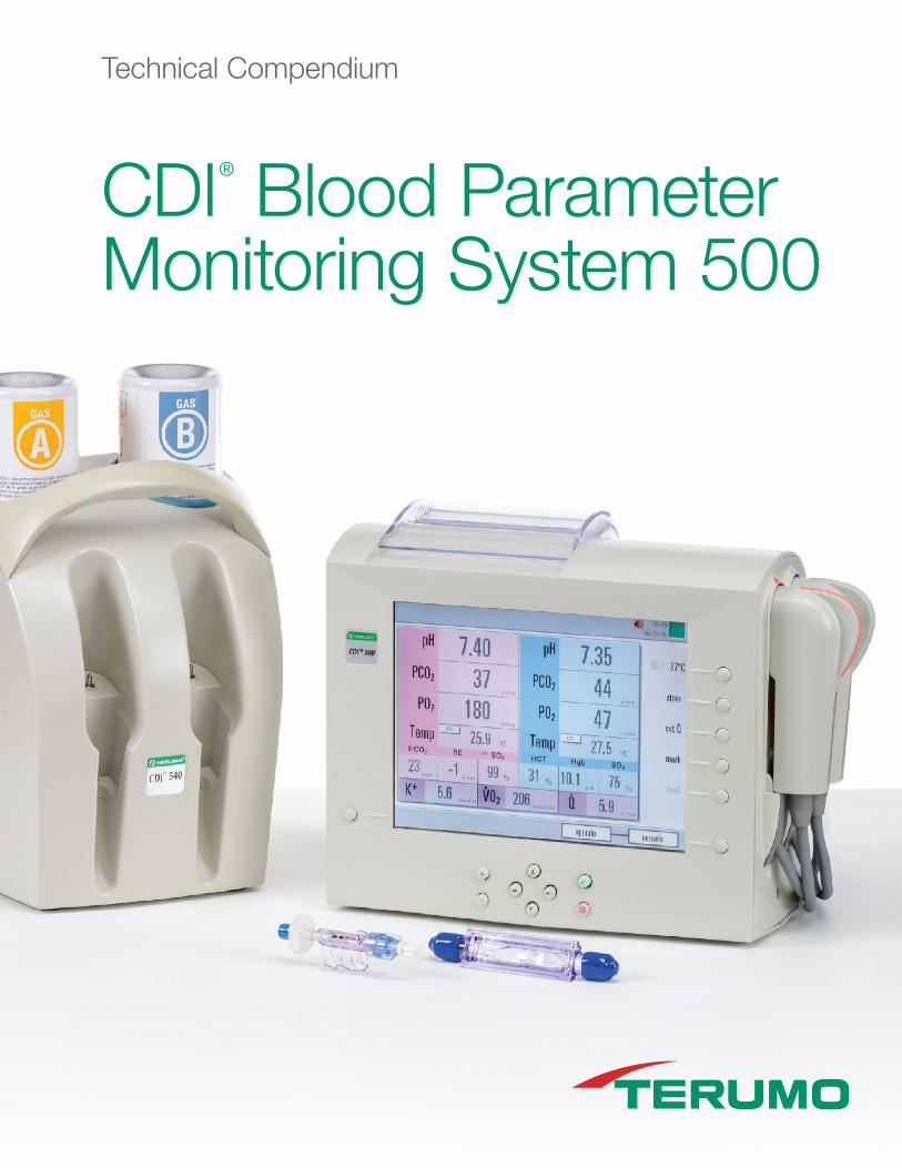
CDI® Blood Parameter Monitoring System 500
Technical Compendium

Technical Compendium CDI® Blood Parameter Monitoring System 500
CDI® Blood Parameter Monitoring System 500
System Overview
The CDI System 500 consists of a monitor to process and display data, a user-selected combination of blood parameter modules (BPMs) and a hematocrit/oxygen saturation probe (H/S probe), disposable sterile sensors and H/S cuvette, and a calibrator.
The disposable sensors and H/S cuvette are installed in the corresponding cable heads at a point in the circuit which will allow adequate exposure to blood (see Figure 1).
Users select the combination of BPMs and H/S probe depending on the parameters to be monitored (see Table 1). BPMs, which measure arterial or venous pH, pCO2, pO2, and K+, use optical fluorescence technology in conjunction with the disposable CDI System 500 shunt sensor. The H/S probe, which measures hematocrit, hemoglobin and oxygen saturation, uses optical reflectance technology in conjunction with the disposable H/S cuvette.
Figure 1: Components of the CDI System 500.
Parameters Measured Components Technology Utilized
Arterial, pH, pCO2, pO2, and K+ Arterial BPM with shunt sensor Optical fluorescence
Venous, pH, pCO2, pO2, and K+ Venous BPM with shunt sensor Optical fluorescence
Hct, Hgb, O2 saturation H/S probe with H/S cuvette Optical reflectance
Table 1: Component configurations of the CDI System 500.

Optical Fluorescence with the CDI® Shunt Sensor
The CDI System 500 uses optical fluorescence technology with the shunt sensor to measure pH, pCO2, pO2, and K+ in blood. The shunt sensor contains four microsensors — one each for pH, pCO2, pO2, and K+ — and a thermistor to measure temperature. The microsensors are in direct contact with the blood, enabling rapid response time.
The CDI System 500 shunt sensor can be placed in any arterial or venous shunt or purge line with continuous flow (see Figure 2). A minimum blood flow requirement of 35 mL/min is necessary for proper measurement.
During normal operation of the CDI System 500, light emitting diodes (LEDs) in the cable heads direct light pulses toward the microsensors, which contain fluorescent dyes (see Figure 3). As these pulses strike the microsensors, fluorescent light is emitted. The intensity of the fluorescent light will vary depending on the pH, pCO2, pO2, and K+ in the blood. A photo detector in the cable head measures the intensity of the fluorescent light and converts it to numerical data which is displayed on the monitor screen.
The pH, pCO2, and pO2 measurements are taken every second. The K+ measurement is taken every six seconds.
Cuvette Blood Flow Rates
The CDI System 500 should only be used where there is blood flow through the extracorporeal circuit. To perform accurately, the H/S cuvette requires blood flow rates shown in Table 3.
Optical Reflectance with the CDI H/S Cuvette
The CDI System 500 uses optical reflectance technology with the H/S probe to measure total hemoglobin and percent oxyhemoglobin, which exhibit different absorbance and reflectance characteristics at different wavelengths.
The flow-through H/S cuvette is installed directly in the tubing circuit. A window in the cuvette allows optical measurement without blood contact (see Figure 1).
LEDs in the H/S probe direct light pulses of specific wavelength at the blood through the optical window in the H/S cuvette (see Figure 4). The absorbance characteristics of hemoglobin and oxyhemoglobin can be measured by the photodetector in the H/S probe. Hemoglobin and oxyhemoglobin measurements are taken every 18 milliseconds.
The output of the detector is converted to numerical data which is displayed on the monitor’s screen.
Figure 3: Optical fluorescence: CDl System 500 shunt sensor and BPM cable head.
Figure 4: Optical reflectance: CDI H/S cuvette and probe.
H/S Cuvette Connector Size Min Flow Max Flow
1/2” 1.0 LPM 7.0 LPM
3/8” 0.5 LPM 4.0 LPM
1/4” 0.2 LPM 1.5 LPM
Table 3: Restoration of blood flow above the minimum through the H/S cuvette will restore performance of the system.

www.terumo-cvgroup.com
Technical Compendium CDI® Blood Parameter Monitoring System 500
CDI® 500 Blood Parameter Monitoring System Calibration of the Microsensors
pH, pCO2, pO2 Sensors
Sensors for pH, pCO2, and pO2 are calibrated using a two-point tonometered calibration system, similar to the system used to calibrate the electrodes in laboratory analyzers.
The calibration process uses the CDI Calibrator 540 and two canisters of calibration gases, Gas A and Gas B. The calibration gases contain precise, defined levels of pCO2 and pO2 gases (see Table 4). During calibration, the shunt sensors (attached to the BPM cable heads) are placed in the calibrator, allowing the calibration gases to flow through the buffer solution contained in each shunt sensor. This exposes the microsensors to the gases with known pCO2 and pO2 values. A predefined pH value for each calibration gas is determined by the interaction of the known pCO2 level in the calibration gas with the buffer solution.
To perform the calibration, the system measures the fluorescent intensities emitted by a microsensor as it is exposed to Gas A and then Gas B. It then plots these two fluorescent measurements as a function of the predefined values of the calibration gases (see example for pO2 in Figure 5). The system uses the two points to create a slope and a y-intercept for that parameter. During bypass, as the system measures the fluorescent intensity of the blood in the extracorporeal circuit, it uses the slope and intercept to extrapolate corresponding blood parameter values.
K+ Sensor
Calibration of the K+ microsensor also relies on a two-point slope and intercept calibration process. The slope is defined using the factory-measured value encoded in the calibration code entered from the sensor pouch during the initial calibration sequence (as described in the Operator’s Manual). The intercept point is obtained after the initiation of bypass using the K+ level in a patient blood sample: the sample is drawn; the CDI System 500 K+ reading is stored in the system; the sample is processed using the laboratory analyzer; the analyzer’s value is then entered into the CDI System 500 to recalibrate the stored reading.
H/S Probe
Each H/S probe is precalibrated at the factory for oxygen saturation, hematocrit, and hemoglobin values; and further calibration is not required before going on bypass. To meet system accuracy limits, perform an in vivo calibration as outlined in the Instructions For Use.
Gas A (Model CDI506)
Gas B (Model CDI507)
pH 7.234 pH units 7.611 pH units
pCO2 7.5% ±0.1% (48.1 mm Hg)
2.8% ±0.1% (18.0 mm Hg)
pO2 27.5% ±0.1% (176.4 mm Hg)
4.0% ±0.1% (25.7 mm Hg)
Table 4: Calibrating gas values for the CDI System 500. Balance of gas mixture is nitrogen (N2). Gases measured at 1 atm and 21° C.
Mea
sure
d Fl
oure
scen
t Int
ensi
ty
Blood Parameter Value (mmHg)
Figure 5: Example of a 2-point calibration for pO2 sensor.
Gas B Value (25.7)
Slope
Gas A Value (176.4)
Y-intercept

www.terumo-cvgroup.com
Technical Compendium CDI® Blood Parameter Monitoring System 500
CDI® System 500 Measures or Calculates 11 Critical Blood ParametersThe CDI Blood Parameter Monitoring System 500 (CDI System 500) was designed and developed to enable continuous monitoring of in-line blood parameters — pH, pCO2, pO2, potassium (K+), oxygen saturation, hematocrit, hemoglobin, and temperature — during cardiopulmonary bypass (CPB). Using optical fluorescence and reflectance technologies and
disposable sensors placed in the extracorporeal circuit, the CDI System 500 monitors and displays real-time changes in blood parameters.
The system provides continuous results and also eliminates the need to consume or dispose of blood samples, as is required in laboratory analyzers.
Figure 2: The CDI System 500 shunt sensors and cuvette are placed in the extracorporeal circuit allowing real-time response to changes in blood parameters.
Mean Standard
pH Sensor -0.018 0.023
pCO2 Sensor -0.2 2.2
pO2 Sensor – Arterial (>80 mm Hg)
6.1 17.6
pO2 Sensor – Venous (<80 mm Hg)
1.3 2.3
Oxygen Saturation Value -0.4 1.6
Temperature -0.07 0.22
Total Hemoglobin Value -0.09 0.38
Potassium Sensor -0.06 0.19
Hematocrit Value -0.4 1.2
System Accuracy Limits
The CDI System 500 has been subjected to rigorous bench tests to simulate the clinical use of the device and assessed for accuracy and precision over the system operating ranges of the measured parameters. Blood samples taken from the test circuit were analyzed in conventional analyzers, and these results were compared (on a sample-by-sample basis) to analyses provided by the CDI System 500.
Table 2 shows the mean difference between the two measurement techniques, and the standard deviation of the differences found.
Table 2: Mean measurement technique and standard deviation differences found.
For information on Terumo Cardiovascular Group products:
Terumo Cardiovascular Group6200 Jackson RoadAnn Arbor, MI 48103-9300USATel: +1.734.663.4145Fax: +1.734.663.7981 www.terumo-cvgroup.com
Terumo Corporation 44-1, 2-chome, HatagayaShibuya-Ku, Tokyo 151-0072 Japan Tel: +81.3.3374.8111 Fax: +81.3.3374.8399www.terumo.co.jp
Terumo Europe N.V. Authorized EC Representative Interleuvenlaan 40, 3001 Leuven Belgium Tel: +32.16.38.12.11 Fax: +32.16.40.02.49 www.terumo-europe.com
Terumo Europe N.V. Cardiovascular Division Ludwig-Erhard-Strasse 6 65760 Eschborn GermanyTel: +49.6196.8023.0Fax: +49.6196.8023.555
Terumo Latin America Corporation 8750 NW 36th Street, Suite 600 Miami, FL 33178 USA Tel: +1.305.477.4822 Fax: +1.305.477.4872
Terumo CorporationDubai BranchAl Masraf Tower, 22nd FloorP.O. Box 20291, DubaiUAETel: +971.4.2212220 Fax: +971.4.2213330
Terumo India Pvt. Ltd. Unit No. 1601 & 1602 Tower B 16th Floor, Unitech Cyber Park Sector-39 Gurgaon, Haryana 122001IndiaTel: +91.124.4718700Fax: +91.124.4718718
Terumo Asia Holdings Pte. Ltd.300 Beach Road#33-03 The Concourse 199555SingaporeTel: +65.6.295.1792Fax: +65.6.294.2329
Terumo® is a registered trademark of Terumo Corporation. CDI® is a registered trademark of Terumo Cardiovascular Systems Corporation. ©2016 Terumo Cardiovascular Systems Corporation. January 2016. 869407
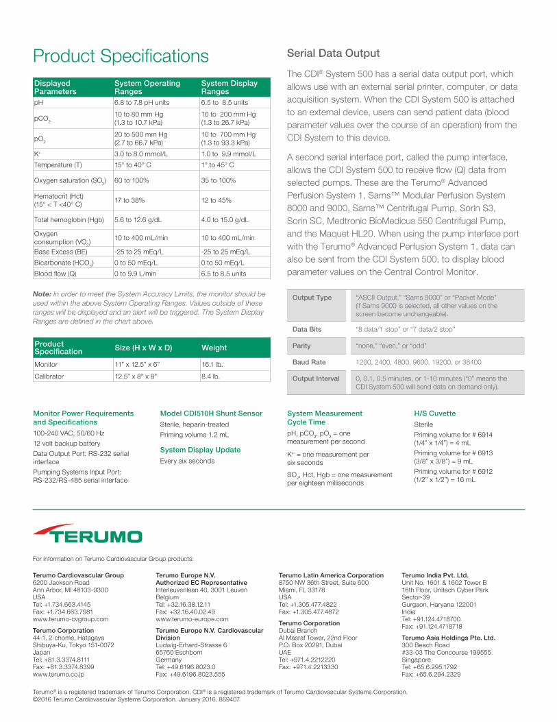
Product Specifications
Monitor Power Requirements and Specifications
100-240 VAC, 50/60 Hz
12 volt backup battery
Data Output Port: RS-232 serial interface
Pumping Systems Input Port: RS-232/RS-485 serial interface
Model CDI510H Shunt Sensor
Sterile, heparin-treated
Priming volume 1.2 mL
System Display Update
Every six seconds
System Measurement Cycle Time
pH, pCO2, pO2 = one measurement per second
K+ = one measurement per six seconds
SO2, Hct, Hgb = one measurement per eighteen milliseconds
H/S Cuvette
Sterile
Priming volume for # 6914 (1/4” x 1/4”) = 4 mL
Priming volume for # 6913 (3/8” x 3/8”) = 9 mL
Priming volume for # 6912 (1/2” x 1/2”) = 16 mL
Output Type “ASCII Output,” “Sarns 9000” or “Packet Mode” (if Sarns 9000 is selected, all other values on the screen become unchangeable).
Data Bits “8 data/1 stop” or “7 data/2 stop”
Parity “none,” “even,” or “odd”
Baud Rate 1200, 2400, 4800, 9600, 19200, or 38400
Output Interval 0, 0.1, 0.5 minutes, or 1-10 minutes (“0” means the CDI System 500 will send data on demand only).
Serial Data Output
The CDI® System 500 has a serial data output port, which allows use with an external serial printer, computer, or data acquisition system. When the CDI System 500 is attached to an external device, users can send patient data (blood parameter values over the course of an operation) from the CDI System to this device.
A second serial interface port, called the pump interface, allows the CDI System 500 to receive flow (Q) data from selected pumps. These are the Terumo® Advanced Perfusion System 1, Sarns™ Modular Perfusion System 8000 and 9000, Sarns™ Centrifugal Pump, Sorin S3, Sorin SC, Medtronic BioMedicus 550 Centrifugal Pump, and the Maquet HL20. When using the pump interface port with the Terumo® Advanced Perfusion System 1, data can also be sent from the CDI System 500, to display blood parameter values on the Central Control Monitor.
Note: In order to meet the System Accuracy Limits, the monitor should be used within the above System Operating Ranges. Values outside of these ranges will be displayed and an alert will be triggered. The System Display Ranges are defined in the chart above.
Displayed Parameters
System Operating Ranges
System Display Ranges
pH 6.8 to 7.8 pH units 6.5 to 8.5 units
pCO2
10 to 80 mm Hg (1.3 to 10.7 kPa)
10 to 200 mm Hg (1.3 to 26.7 kPa)
pO2
20 to 500 mm Hg (2.7 to 66.7 kPa)
10 to 700 mm Hg (1.3 to 93.3 kPa)
K+ 3.0 to 8.0 mmol/L 1.0 to 9.9 mmol/L
Temperature (T) 15° to 40° C 1° to 45° C
Oxygen saturation (SO2) 60 to 100% 35 to 100%
Hematocrit (Hct) (15° < T <40° C)
17 to 38% 12 to 45%
Total hemoglobin (Hgb) 5.6 to 12.6 g/dL 4.0 to 15.0 g/dL
Oxygen consumption (VO2)
10 to 400 mL/min 10 to 400 mL/min
Base Excess (BE) -25 to 25 mEq/L -25 to 25 mEq/L
Bicarbonate (HCO3) 0 to 50 mEq/L 0 to 50 mEq/L
Blood flow (Q) 0 to 9.9 L/min 6.5 to 8.5 units
Product Specification Size (H x W x D) Weight
Monitor 11” x 12.5” x 6” 16.1 lb.
Calibrator 12.5” x 8” x 8” 8.4 lb.