c:documentationbale mover 5-7bm5-7 ops … · adjust position of the tongue plate ... drive up to...
TRANSCRIPT

O p e r a t o r s M a n u a l
E14995V1
Bale MoverBM607/BM605

Operator’sManual
Highline Manufacturing LimitedHWY #27, P.O. Box 307
Vonda, SK S0K 4N0Canada
Phone: 306.258.2233Fax: 306.258.2010
Toll Free: 1.800.665.2010
E14995V1
Bale Mover 605
Bale Mover 607
Printed in Canada Copyright © 2016 by Highline Manufacturing Ltd. All rights reserved.
The content of this manual was based on the most current information available as of the date of copyright. It is the policy ofHighline Manufacturing Limited to improve and develop our products continually. We reserve the right to make changes or addimprovements, at any time, without incurring any obligation to make changes or improvements on machines previously sold.Changes may not be reflected in this manual.

Highline Manufacturing Ltd. Bale Mover 605/607
Highline Team Message
Congratulations on your purchase of the Bale Mover 605/607 manufactured by HighlineManufacturing Ltd.
This Operator’s Manual has been prepared to provide information necessary for the safe andefficient operation of your Bale Mover. In the manual you will find safety procedures,maintenanceroutines and detailed operational instructions.
If you find that you require information not covered in this manual, please feel free to consultyour local dealer. Your dealer is always able to contact Highline for this technical information.
Highline Manufacturing Ltd. thanks and congratulates you for selecting a Bale Mover 605/607as your machine of choice.
Highline Manufacturing Ltd.

Table of Contents
Section 1 - Safety
Serial Number . . . . . . . . . . . . . . . . . . . . . . . . . . . . . . . . . . . . . . . . . . . . . . . . . . . . . . . . . . . . . . . . . . . . . . 1Safety Sign-off Form . . . . . . . . . . . . . . . . . . . . . . . . . . . . . . . . . . . . . . . . . . . . . . . . . . . . . . . . . . . . . . . . . 2Safety Alert Symbol . . . . . . . . . . . . . . . . . . . . . . . . . . . . . . . . . . . . . . . . . . . . . . . . . . . . . . . . . . . . . . . . . . 3General Safety . . . . . . . . . . . . . . . . . . . . . . . . . . . . . . . . . . . . . . . . . . . . . . . . . . . . . . . . . . . . . . . . . . . . . . 4Safety Decals . . . . . . . . . . . . . . . . . . . . . . . . . . . . . . . . . . . . . . . . . . . . . . . . . . . . . . . . . . . . . . . . . . . . . . . 4Safety Decal Locations . . . . . . . . . . . . . . . . . . . . . . . . . . . . . . . . . . . . . . . . . . . . . . . . . . . . . . . . . . . . . . . 9
Section 2 - Transporting the Bale Mover
Tractor requirements . . . . . . . . . . . . . . . . . . . . . . . . . . . . . . . . . . . . . . . . . . . . . . . . . . . . . . . . . . . . . . . . . 1Lift the hitch . . . . . . . . . . . . . . . . . . . . . . . . . . . . . . . . . . . . . . . . . . . . . . . . . . . . . . . . . . . . . . . . . . . . . . . . 1Adjust position of the tongue plate . . . . . . . . . . . . . . . . . . . . . . . . . . . . . . . . . . . . . . . . . . . . . . . . . . . . . . . 1Connect the hitch to the tractor drawbar. . . . . . . . . . . . . . . . . . . . . . . . . . . . . . . . . . . . . . . . . . . . . . . . . . . 2Connect the safety chain to the tractor . . . . . . . . . . . . . . . . . . . . . . . . . . . . . . . . . . . . . . . . . . . . . . . . . . . 2Attach the hydraulic hoses . . . . . . . . . . . . . . . . . . . . . . . . . . . . . . . . . . . . . . . . . . . . . . . . . . . . . . . . . . . . . 2Connect the lighting cable . . . . . . . . . . . . . . . . . . . . . . . . . . . . . . . . . . . . . . . . . . . . . . . . . . . . . . . . . . . . . 3Connect to the control switch . . . . . . . . . . . . . . . . . . . . . . . . . . . . . . . . . . . . . . . . . . . . . . . . . . . . . . . . . . . 3Place the hitch jack in the storage location . . . . . . . . . . . . . . . . . . . . . . . . . . . . . . . . . . . . . . . . . . . . . . . . 3Lower the bale mover deck . . . . . . . . . . . . . . . . . . . . . . . . . . . . . . . . . . . . . . . . . . . . . . . . . . . . . . . . . . . . 3Check the condition of all the tires . . . . . . . . . . . . . . . . . . . . . . . . . . . . . . . . . . . . . . . . . . . . . . . . . . . . . . . 4Raise the bale lift arm . . . . . . . . . . . . . . . . . . . . . . . . . . . . . . . . . . . . . . . . . . . . . . . . . . . . . . . . . . . . . . . . 4Remove the lift arm transport lock from the storage position . . . . . . . . . . . . . . . . . . . . . . . . . . . . . . . . . . 5Install the lift arm transport lock . . . . . . . . . . . . . . . . . . . . . . . . . . . . . . . . . . . . . . . . . . . . . . . . . . . . . . . . 5Swing the lights and the Slow Moving Vehicle (SMV) sign out to be visible . . . . . . . . . . . . . . . . . . . . . . . 6Ensure the lights are working . . . . . . . . . . . . . . . . . . . . . . . . . . . . . . . . . . . . . . . . . . . . . . . . . . . . . . . . . . . 6Transport Speed . . . . . . . . . . . . . . . . . . . . . . . . . . . . . . . . . . . . . . . . . . . . . . . . . . . . . . . . . . . . . . . . . . . . 6
Section 3 - Bale Mover Preparation
Park the tractor and Bale Mover on level ground. . . . . . . . . . . . . . . . . . . . . . . . . . . . . . . . . . . . . . . . . . . . 1Pivot the lights and SMV in toward the rails and pin in place . . . . . . . . . . . . . . . . . . . . . . . . . . . . . . . . . . . 1Adjust the deck chain rails for the size and condition of the bales. . . . . . . . . . . . . . . . . . . . . . . . . . . . . . . 1Check the condition of both bale chains . . . . . . . . . . . . . . . . . . . . . . . . . . . . . . . . . . . . . . . . . . . . . . . . . . 2Check the tension on both chains . . . . . . . . . . . . . . . . . . . . . . . . . . . . . . . . . . . . . . . . . . . . . . . . . . . . . . . 3Remove the transport lock from the bale lift arm cylinder . . . . . . . . . . . . . . . . . . . . . . . . . . . . . . . . . . . . . 3Place transport arm lock in the storage location . . . . . . . . . . . . . . . . . . . . . . . . . . . . . . . . . . . . . . . . . . . . 4Attach the hydraulic hoses . . . . . . . . . . . . . . . . . . . . . . . . . . . . . . . . . . . . . . . . . . . . . . . . . . . . . . . . . . . . . 4Connect the control cable . . . . . . . . . . . . . . . . . . . . . . . . . . . . . . . . . . . . . . . . . . . . . . . . . . . . . . . . . . . . . 4Lower the bale lift arm . . . . . . . . . . . . . . . . . . . . . . . . . . . . . . . . . . . . . . . . . . . . . . . . . . . . . . . . . . . . . . . . 5Set the width of the bale lift arm . . . . . . . . . . . . . . . . . . . . . . . . . . . . . . . . . . . . . . . . . . . . . . . . . . . . . . . . . 5Check that the bale lift arm operates freely when lifting . . . . . . . . . . . . . . . . . . . . . . . . . . . . . . . . . . . . . . 6Check that the chain guards . . . . . . . . . . . . . . . . . . . . . . . . . . . . . . . . . . . . . . . . . . . . . . . . . . . . . . . . . . . 6Ensure the chains operate smoothly . . . . . . . . . . . . . . . . . . . . . . . . . . . . . . . . . . . . . . . . . . . . . . . . . . . . . 7Check the condition of the tires . . . . . . . . . . . . . . . . . . . . . . . . . . . . . . . . . . . . . . . . . . . . . . . . . . . . . . . . . 7Remove any twine or netwrap that maybe built up . . . . . . . . . . . . . . . . . . . . . . . . . . . . . . . . . . . . . . . . . . 7Inspect all the hydraulic cylinders and hoses . . . . . . . . . . . . . . . . . . . . . . . . . . . . . . . . . . . . . . . . . . . . . . . 8Check the condition of the hydraulic motors . . . . . . . . . . . . . . . . . . . . . . . . . . . . . . . . . . . . . . . . . . . . . . . 8

Section 4 - Operating the Bale Mover
Remove the lift arm transport lock . . . . . . . . . . . . . . . . . . . . . . . . . . . . . . . . . . . . . . . . . . . . . . . . . . . . . . 1Place transport arm lock in the storage location . . . . . . . . . . . . . . . . . . . . . . . . . . . . . . . . . . . . . . . . . . . . 1Bale Mover should be operated at field speeds . . . . . . . . . . . . . . . . . . . . . . . . . . . . . . . . . . . . . . . . . . . . 2Load the Bale Mover from the right side . . . . . . . . . . . . . . . . . . . . . . . . . . . . . . . . . . . . . . . . . . . . . . . . . . 2
Loading Bales in the Field . . . . . . . . . . . . . . . . . . . . . . . . . . . . . . . . . . . . . . . . . . . . . . . . . . . . . . . . . . . . . 3
Tractor Cab Controller Operating Modes . . . . . . . . . . . . . . . . . . . . . . . . . . . . . . . . . . . . . . . . . . . . . . . . . 3Lower the bale lift arm . . . . . . . . . . . . . . . . . . . . . . . . . . . . . . . . . . . . . . . . . . . . . . . . . . . . . . . . . . . . . . . . 4Drive up to the bale and position . . . . . . . . . . . . . . . . . . . . . . . . . . . . . . . . . . . . . . . . . . . . . . . . . . . . . . . . 4Drive forward until the lift arm forks are fully under the bale . . . . . . . . . . . . . . . . . . . . . . . . . . . . . . . . . . . 5Activate the hydraulic remote to lift the arm . . . . . . . . . . . . . . . . . . . . . . . . . . . . . . . . . . . . . . . . . . . . . . . 5Automatic Bale Advance . . . . . . . . . . . . . . . . . . . . . . . . . . . . . . . . . . . . . . . . . . . . . . . . . . . . . . . . . . . . . . 6Manual Bale Advance . . . . . . . . . . . . . . . . . . . . . . . . . . . . . . . . . . . . . . . . . . . . . . . . . . . . . . . . . . . . . . . . . 7Indicator on the front of the right rail . . . . . . . . . . . . . . . . . . . . . . . . . . . . . . . . . . . . . . . . . . . . . . . . . . . . . 7Drive to the bale storage site . . . . . . . . . . . . . . . . . . . . . . . . . . . . . . . . . . . . . . . . . . . . . . . . . . . . . . . . . . . 8Traveling on roadways . . . . . . . . . . . . . . . . . . . . . . . . . . . . . . . . . . . . . . . . . . . . . . . . . . . . . . . . . . . . . . . . 8
Unloading Bales . . . . . . . . . . . . . . . . . . . . . . . . . . . . . . . . . . . . . . . . . . . . . . . . . . . . . . . . . . . . . . . . . . . . . 9Tractor Cab Controller . . . . . . . . . . . . . . . . . . . . . . . . . . . . . . . . . . . . . . . . . . . . . . . . . . . . . . . . . . . . . . . . 9
Reloading Bales . . . . . . . . . . . . . . . . . . . . . . . . . . . . . . . . . . . . . . . . . . . . . . . . . . . . . . . . . . . . . . . . . . . . 12Tractor Cab Controller . . . . . . . . . . . . . . . . . . . . . . . . . . . . . . . . . . . . . . . . . . . . . . . . . . . . . . . . . . . . . . . 12
Section 5 - Maintaining the Bale Mover
Shutdown Procedure . . . . . . . . . . . . . . . . . . . . . . . . . . . . . . . . . . . . . . . . . . . . . . . . . . . . . . . . . . . . . . . . . 1Lubrication . . . . . . . . . . . . . . . . . . . . . . . . . . . . . . . . . . . . . . . . . . . . . . . . . . . . . . . . . . . . . . . . . . . . . . . . . 1Chain Adjustment Procedure . . . . . . . . . . . . . . . . . . . . . . . . . . . . . . . . . . . . . . . . . . . . . . . . . . . . . . . . . . . 2Visually Inspect Hydraulic Hoses/Fittings . . . . . . . . . . . . . . . . . . . . . . . . . . . . . . . . . . . . . . . . . . . . . . . . . . 3Tire Changing Procedure . . . . . . . . . . . . . . . . . . . . . . . . . . . . . . . . . . . . . . . . . . . . . . . . . . . . . . . . . . . . . . 4Tire Pressure . . . . . . . . . . . . . . . . . . . . . . . . . . . . . . . . . . . . . . . . . . . . . . . . . . . . . . . . . . . . . . . . . . . . . . . 4
Section 6 - Storing the Bale Mover
Clean all the debris off . . . . . . . . . . . . . . . . . . . . . . . . . . . . . . . . . . . . . . . . . . . . . . . . . . . . . . . . . . . . . . . . 1Lubricate all Bale Mover grease points . . . . . . . . . . . . . . . . . . . . . . . . . . . . . . . . . . . . . . . . . . . . . . . . . . . 1Lubricate the bale chains . . . . . . . . . . . . . . . . . . . . . . . . . . . . . . . . . . . . . . . . . . . . . . . . . . . . . . . . . . . . . 1Park the Bale Mover on level ground . . . . . . . . . . . . . . . . . . . . . . . . . . . . . . . . . . . . . . . . . . . . . . . . . . . . . 1Lower the Bale Mover deck . . . . . . . . . . . . . . . . . . . . . . . . . . . . . . . . . . . . . . . . . . . . . . . . . . . . . . . . . . . . 1Lower the lift arm to the ground . . . . . . . . . . . . . . . . . . . . . . . . . . . . . . . . . . . . . . . . . . . . . . . . . . . . . . . . . 2Raise the hitch until the weight is supported by the jack . . . . . . . . . . . . . . . . . . . . . . . . . . . . . . . . . . . . . . 2Disconnect the hitch . . . . . . . . . . . . . . . . . . . . . . . . . . . . . . . . . . . . . . . . . . . . . . . . . . . . . . . . . . . . . . . . . 3Relieve the pressure on the hydraulic hoses and disconnect them . . . . . . . . . . . . . . . . . . . . . . . . . . . . . . 3Disconnect the electrical connection . . . . . . . . . . . . . . . . . . . . . . . . . . . . . . . . . . . . . . . . . . . . . . . . . . . . . 3Secure the hydraulic hoses and electrical connectors . . . . . . . . . . . . . . . . . . . . . . . . . . . . . . . . . . . . . . . 3
Section 7 - Troubleshooting
Specifications

This Page Left Blank

GENERAL DESCRIPTION OF THE BALE MOVER
The Bale Mover is designed to pick up round bales while driving in the field without the need tostop to pick up a bale.
The bale pickup fork is lowered and positioned by the tractor driver to slide around the lowerportion of the bale. The pickup fork is raised for the bale to be placed on the bale rail. Thechains on the rail moves the bale back to give room for another bale to be loaded. Five or sevenround bales (depending on model) can be loaded on the right side of the machine. The balemover has the capacity of loading and moving 5 or 7 (depending on model) round bales.
The Bale Mover has an automatic advance system to move the bales back to allow for room forthe next bale to be loaded onto the chains. The automatic advance system can be turned on oroff at the operator’s discretion. The bale chains can be operated manually.
The Bale Mover has a 90 degree turn bale fork to automatically turn bales for non-stop loadingfrom virtually any angle. Bales can be picked up from the right side of the machine withouthaving to reposition the machine. The bale fork and chain rails can be adjusted for differentsizes of round bales and for the conditions of the bales.
For unloading bales, the back end of the deck of the bale mover is lowered. As the Bale Moveris driven forward, the bale chains are rotated to assist in the easy unloading of the row of bales.
A row of bales can also be loaded onto the Bale Mover by lowering the back end of the deck,rotating the bale chains to move bales onto the deck while backing the Bale Mover into the rowof bales.
When the Bale Mover is engaged it uses hydraulic power from the tractor to lower and raise thebale fork. The hydraulics are also used to operate the bale chains to move the bales. The deckis raised or lowered using the tractor hydraulics.
The operator of the Bale Mover is located in the tractor cab where they drive the tractor, controlthe speed of driving and the operation of the bale fork and the bale chains.
The Bale Mover is transported with the Bale fork lifted and locked in position.
INTENDED USE OF THE BALE MOVER
• The Bale Mover is designed to pick up round bales that are in the field and move them toa storage location where they are placed in rows.
• The Bale Mover is designed to pick up round bales that have been previously placed in arow and move them to another location.
• The bales have previously been made using a round baler.
The Bale Mover is intended for use in field farming applications. The Bale Mover is intended for use in locations that are not near people or animals who couldbe harmed by the movement of the bale loading fork or the unloading of bales from the deck.

Any uses of the Bale Mover other than the above stated Intended Uses shall be consideredmisuse of the Bale Mover. This misuse shall included (but not limited to):
- Using the Bale Mover in non-farming applications.- Using the Bale Mover around people or in public places.- Moving materials other than round bales from fields.- Using the bale fork to lift objects other than round bales.
Always use the Bale Mover according to the instructions contained in this Operator's Manual andthe safety and instruction decals on the machine.
Perform regular maintenance and repair to ensure that the Bale Mover operates safely andefficiently.
Bale Mover 605/607
The Bale Mover has the ability to pickupround bales from the right. It can carry 5 or 7bales depending on the model. It easilyunloads the bales by tilting the deck, drivingahead while the bale chains move the balesoff the deck.
The Bale Mover can also reload rows ofbales to be moved to another location. Toreload, tilt the deck and backup while thebale chains move the bales onto the deck.
Bale Mover 607 214141 Unloading or Reloading Bales 214142

This Page Left Blank

Section 1 - Safety
SERIAL NUMBER
Your serial number is found on the serial number plate (1) attached to the inside of the leftrail near the motor mount.
It is important to record the serial number for proof of ownership and for any service ormaintenance assistance.
Serial Number
Owner
Model
Date of Purchase
Be Trained Before Operating!
Serial Number Plate Location 215054C
Page 1-1

Section 1 - Safety
SAFETY SIGN-OFF FORM
Highline Manufacturing Ltd. follows the general Safety Standards specified by the AmericanSociety of Agricultural Engineers (ASAE) and the Occupational Safety and Health Administration(OSHA). Anyone who will be operating and/or maintaining the Highline Bale Mover should readand clearly understand all Safety, Operating and Maintenance information presented in thismanual.
Do not operate or allow someone to operate this equipment until this information has beenreviewed. This information should be reviewed by all operator’s before the season start-up.
This sign-off sheet is provided for record keeping to indicate that the person working with theequipment has read and understood the information in the Operator’s Manual and has beeninstructed in the safe operation of the equipment.
Date Employee’s Signature Employer’s Signature
Page 1-2

Section 1 - Safety
SAFETY ALERT SYMBOL
The Safety Alert Symbol means:
ATTENTION!BECOME ALERT!YOUR SAFETY IS INVOLVED!
The Safety Alert Symbol combined with a Signal Word alert to the presence of a hazard and thedegree of possible injury.
Indicates an imminently hazardous situation that, i f notavoided, WILL result in DEATH OR SERIOUS INJURY.The color is Red with White lettering.
Indicates a potentially hazardous situation that, i f notavoided, COULD result in DEATH OR SERIOUSINJURY, and includes hazards that are exposed whenguards are removed or unsafe practices. The color i sOrange with Black lettering.
Indicates a potentially hazardous situation that, i f notavoided, MAY result in MINOR INJURY. The color isYellow with Black lettering.
Page 1-3

Section 1 - Safety
GENERAL SAFETY
1. Ensure that anyone who is going to operate, maintain or work near the Bale Mover is familiarwith the recommended operating, maintenance procedures and safety information containedin this manual and follows all the safety precautions.
2. In addition to the design and configuration of the equipment, hazard control and accidentprevention are dependant upon the awareness, concern, prudence and proper training ofpersonnel involved in the operation, transport, maintenance and storage of the Bale Mover.
3. The Bale Mover shall not be operated without all the guards in place.
SAFETY DECALS
1. Keep decals and signs clean and legible at all times.2. Replace decals and signs that are damaged, missing or have become illegible.3. Replaced parts that displayed a decal should also display the current decal.4. Decals are available from the Highline Parts Department.5. Be familiar with the decals, the type of warning and the area or function(s) related to the
area(s) that requires your awareness.
Page 1-4

Section 1 - Safety
STAY AWAY FROM OVERHEAD POWER LINES
Stay away from power lines when transporting or foldingequipment. Electrocution can occur without contacting power lines.
READ, UNDERSTAND, AND FOLLOW SAFETY INSTRUCTIONS
Read, understand and follow all instructions and safety messagesincluded in this manual and on decals attached to the machine.
Allow only responsible, properly instructed individuals to operateand service the machine.
Failure to follow the instructions and safety messages in thismanual and on the decals attached to the machine could result inserious injury or death.
Keep all safety and instruction decals in good condition. Replaceany missing or damaged decals.
STOP TRACTOR BEFORE GOING NEAR MACHINE
Always disengage power take off, shut off tractor, remove key, setpark brake and wait for all parts to stop turning before servicing.
KEEP PEOPLE BACK WHEN LOADING OR UNLOADINGBALES
Falling bales can cause serious injury or death.Stand clear of Bale Mover when PTO is engaged.Do not operate within 100 ft (30m) of any person.
Page 1-5

Section 1 - Safety
STAND CLEAR OF BALE LIFT ARMS
Moving lift arm can cause serious injury or death.Never stand under lift arms when lowering or raising.Do not allow people near the lift arms when being moved.Lift arms must be fully retracted and locked in place beforeservicing.
Install arm lock chains before transporting bale mover.
DO NOT PLACE HANDS IN THE HINGING AREA WHENRAISING OR LOWERING BALE LIFT ARM
Pinch hazard could cause serious injury or death when raising orlowering lift arm if hands are placed between the hinge area orbetween the arm and rubber stop.
STAY CLEAR OF DECK WHEN RAISING OR LOWERING
There is a crushing hazard if limbs or body is placed between thedeck and ground or surrounding objects when the deck is raised orlowered.
STAY CLEAR OF DECK WHEN IT IS TILTED
There is a crushing hazard if limbs or body is placed between thehitch and deck when the deck is tilted.The deck could be lowered or come down causing serious injury ordeath.
Page 1-6

Section 1 - Safety
UPENDING HAZARD
The hitch can rise rapidly when there are bales on the end of therails but not at the front of the rails.
Use a clevis to attach to towing machine.
Ensure implement is attached to machine before hydraulics areactivated.
DO NOT RIDE ON MACHINE
Falling from the moving machine can cause serious injury ordeath.Falling from the operating machine can cause being entangledunder the machine or being injured by the machine.
USE PAPER OR CARDBOARD TO CHECK FOR HYDRAULICLEAKS
To prevent serious injury or death:Relieve pressure on hydraulic system before repairing, adjusting ordisconnecting.Wear proper hand and eye protection when searching for leaks.Use wood or cardboard instead of hands.Keep all components in good repair.
Fluid injected under the skin must be removed immediately by asurgeon familiar with this type of injury.
DO NOT OPERATE WITH SHIELDS MISSING
Close and secure guards and shields before starting machine.
Keep hand, feet, hair and clothing away from moving parts.
Contact with moving chains or parts could cause serious injury ordeath. Stay clear of moving chain and idler.
Page 1-7

Section 1 - Safety
DO NOT CONTACT MOVING CHAIN
Contacting moving chain or parts could cause serious injury or death.
Never attempt to manually remove bales from rails while hydraulicmotors are moving the chain.Disconnect chain drive hydraulic motors before cleaning the BaleMover.
Always disengage power take off, shut off tractor, remove key, setpark brake and wait for all parts to stop turning before servicing.
ENSURE SLOW MOVING VEHICLE SIGN IS IN PLACE
Ensure the Slow Moving Vehicle sign is in place, clean and easilyvisible.
Ensure the reflectors are in place, clean and easily visible.
Page 1-8

Section 1 - Safety
BM607_A
SAFETY DECAL LOCATIONS
Page 1-9

Section 1 - Safety
This Page Left Blank
Page 1-10

Section 2 - Transporting the Bale Mover
2.0 Transporting the Bale Mover
Only tow the Bale Mover behind aproperly sized and equippedtractor or vehicle which exceedsthe weight of the loaded BaleMover by 50%.
Shut off the tractor engine beforeattaching the bale mover orhydraulics.
Do not allow children or otherpeople to ride on the tractor orBale Mover. Falling off can resultin serious injury or death.
1. Tractor requirements.- Roll Over Protection System (ROPS)- Working seatbelts- 2 Spool Control Valves (SCV)
2. Lift the hitch.
- Lift the hitch with the jack.- Do not attempt to lift the hitch
without using the jack.
3. Adjust position of the tongue plate.
- Level the bale mover by using thehitch jack.
- Remove the tongue plate bolts andmove the tongue plate so that the balemover is level when connected to thetractor drawbar.
- Fasten in place.
Lift the Hitch, Adjust Position of Tongue Plate 214143
Page 2-1

Section 2 - Transporting the Bale Mover
4. Connect the hitch to the tractor drawbar.
- Use at least a 1 1/4" (31.75 mm) pin.
5. Connect the safety chain to the tractorand fasten securely.
6. Tractor wheel tread width settings.- When working on inclines or rough
ground, use the largest tractor wheelwidth possible to maintain tractorstability.
7. Attach the hydraulic hoses.
- Clean the end of the hoses and theconnection.
- Firmly push the hoses into the tractorreceptacle according to userpreference.
- Route the hoses so they do notinterfere with moving parts.
Connect the Hitch and Safety Chain 215032
Attach Hydraulics and Lighting 201199
Page 2-2

Section 2 - Transporting the Bale Mover
8. Connect the lighting cable to the electricalconnection on the tractor.
9. Route the electric control cable from thehitch into the tractor cab and connect tothe control switch.
- Ensure the cable does not interferewith or contact moving parts.
- Connect the switch to the battery for12 volt power supply. Connect withthe ring connectors.
10. Place the hitch jack in the storagelocation.
- Remove all weight from the jack.
- Remove the locking pin holding thejack onto the hitch.
- Place the jack to the storage position(1).
- Fasten the jack in place with the lockpin.
11. Lower the bale mover deck.
- Fully retract the deck lift cylinder sothe bale deck is sitting on the frame ofthe bale mover.
Lower the Deck 214146
Jack in the Storage Location 216040C
Page 2-3

Section 2 - Transporting the Bale Mover
214147
12. Check the condition of all the tires.
- Ensure that the lug nuts have thecone side of the lug nut against thewheel rim.
- Torque the lug nuts to 75 lb-ft (101Nm).
- Fill the tires to 52 psi (358 Kpa).
13. Raise the bale lift arm.
Stand Clear of the Bale Lift arm.
A moving lift arm can causeserious injury or death.Never stand under the lift armwhen lowering or raising.Do not allow people near the liftarm when being moved.
- Activate the hydraulic cylinder to liftthe bale lift arm.
Tires 107094CC
Page 2-4

Section 2 - Transporting the Bale Mover
14. Remove the lift arm transport lockfrom the storage position.
- Remove the clip pin (2) from thestorage tab.
- Remove the arm cylinder lock (1) fromthe storage tab.
15. Install the lift arm transport lock (1) onthe lift arm onto the bale mover frame.
Always use the fork transport lockwhen transporting the Bale Moveron public roads. The fork maydescend rapidly if hydraulicpressure is lost to the lift cylinder.
- Install the arm lock (1) over thecylinder rod.
- Fasten in place with the clip pin (2).
Remove Lift Arm Lock from Storage 216033C
Lift Arm Transport Lock 216034C
Page 2-5

Section 2 - Transporting the Bale Mover
Stay away from overhead powerlines. Electrocution can occurwithout contacting power lines
16. Swing the lights and the Slow MovingVehicle (SMV) sign out to be visible.
- Ensure that the Slow MovingVehicle (SMV) sign is clean andvisible.
17. Ensure the lights are working.
18. Transport Speed
- Do not exceed 24 mph (40 km/h).
19. If traveling on roadways:
- Ensure the clearance lights andSMV are pivoted out and visible.
- Ensure the lights are operating.
- Consult the local road regulationsregarding securing the load androad travel. Follow all theapplicable regulations.
Swing Out the SMV and Lights 215002
Page 2-6

Section 3 - Bale Mover Preparation
Suggested Rail Positions for Size of Bale. Adjust for Condition of Bale 216035C
3.0 Bale Mover Preparation
1. Park the tractor and Bale Mover on levelground. Engage the tractor parking brake.
Shut down the tractor and removethe key before repairing, servicing,lubricating or cleaning themachine.Relieve all hydraulic pressure inthe hoses. Disconnect thehydraulic hoses from the tractor before going near the machine.
2. Ensure all decals are clean and in place.
3. For in field operation, pivot the lights andSMV in toward the rails and pin in place.This will prevent the lights from interferingwith the bales.
4. Adjust the deck chain rails for the sizeand condition of the bales.
- Suggested rail positions for bale sizeare shown. Adjust position for the condition of bales.
Page 3-1

Section 3 - Bale Mover Preparation
Check Condition of the Bale Chains 216035
To adjust rail locations:
- Remove the bolts (1) from the railmounts plates along the length of therail.
- Slide the rail to the alternate mountpositions (2) according to the layoutabove.
- Fasten the mount plates with the boltsand nuts.
5. Check the condition of both bale chains.
- Clean debris and material buildupfrom the chain area and the chainchannels.
- Remove dirt and debris from therail openings (1) and the end ofthe rail.
- Blow out dirt with compressed airor flush with water.
- Check that no wire or other materialsare wrapped in the chain.
- Check that the chain is secure aroundthe end roller.
Adjust Rails for Size and Condition of Bale 215003C
Check That Chain Is On The End Roller 215006
Clean Debris from Rail Openings 215026C
Page 3-2

Section 3 - Bale Mover Preparation
6. Check the tension on both chains.
- The chain can be seen in the sighthole (1) that is in the side of the rail.
- The chain should be in line with theimage of the chain that is on the decalat the sight hole.
- Adjust tension as necessary. See“Chain Adjustment Procedure” in theMaintenance Section.
7. Remove the transport lock (1) from thebale lift arm cylinder.
Note: Do not lower the fork when thetransport lock is in position or damageto the machine will occur.
- Remove the clip pin (2) and removethe lock (1) from the cylinder.
Check Tension of the Chains 215007C
Chain Tension E7567_A
Remove Lift Arm Transport Lock 216034C
Page 3-3

Section 3 - Bale Mover Preparation
8. Place transport arm lock in the storagelocation.
- Place the transport arm lock (1) ontothe storage tab located on the side ofthe bale arm.
- Fasten onto the storage tab with theclip pin (2).
9. Attach the hydraulic hoses.
- Clean the end of the hoses and theconnection.
- Firmly push the hoses into the tractorreceptacle according to userpreference.
- Route the hoses so they do notinterfere with moving parts.
10. Connect the control cable at the hitchto the cable that goes to the controlswitch in the cab.
- Ensure the cable does not interferewith or contact moving parts.
- Connect the switch to the battery for12 volt power supply. Use the ringconnectors to make the connection.
Arm Lock In Storage Position 216033C
Attach Hydraulics 201199
Page 3-4

Section 3 - Bale Mover Preparation
11. Lower the bale lift arm.
Stand Clear of Bale Lift Arms
- Moving lift arm can cause seriousinjury or death.
- Never stand under lift arms whenlowering or raising.
- Do not allow people near the liftarms when the being moved.
Note: Do not lower the fork when thetransport lock is in position or damageto the machine will occur.
12. Set the width of the bale lift arm.
- Loosen the bolts on the holding clamp(1).
- Slide the arm to the suit the size of thebale.
- Tighten the bolts on the holdingclamp(1) to fasten to the lift arm.
Slide Clamp for Bale Width 215020C
Page 3-5

Section 3 - Bale Mover Preparation
13. Check that the bale lift arm operatesfreely when lifting.
Stand Clear of Bale Lift Arms
- Moving lift arms can cause seriousinjury or death.
- Never stand under lift arms whenlowering or raising.
- Do not allow people near the liftarms when the being moved.
14. Check that the chain guards (1) on thehydraulic motors are in place and ingood condition.
The Bale Mover shall not beoperated without all the chainguards in place and in goodcondition.
- Replace missing or broken guardsimmediately.
Check that Lift Arm Operates Freely 216041
Ensure Motor Chain Guards Are In Place 215030C
Page 3-6

Section 3 - Bale Mover Preparation
15. Engage the bale chains motors toensure the chains operate smoothly.
Keep clear of moving chains.Contacting with the moving chainor parts could cause serious injuryor death.
16. Check the condition of the tires.
- Fill to an air pressure of 52 psi (358kPa).
- Inspect the wheels and tires fordamage or foreign objects. Repair orreplace as necessary.
17. Remove any twine or netwrap thatmaybe built up around the hubs orother parts of the machine.
Check that Bale Chains Operate Smoothly 216035
Check the Condition of the Tires 214147
Remove Twine from around Hub 215031
Page 3-7

Section 3 - Bale Mover Preparation
18. Inspect all the hydraulic cylinders andhoses.
Use a piece of cardboard orheavy paper to check for leaks.Do not use your hand. Wearproper hand and eye protectionwhen searching for leaks.
Relieve pressure on hydraulicsystem before repairing, adjustingor disconnecting.
Note: If fluid is injected under the skin, itmust be removed immediately by asurgeon familiar with this type ofinjury.
- Visually inspect all the hydraulic hosesand fittings. - See Section 5 "Maintaining the
Bale Mover" for conditionsindicating that replacement isneeded.
- Ensure the proper size cylinder pinsare in place and secured.
19. Check the condition of the hydraulicmotors and the connections.
20. Lubricate all grease fittings. See theMaintenance Section.
21. Ensure all fasteners are tightened.
Check All Hydraulic Connections 215029
Check the Motor and Connections 215030
Page 3-8

Section 4 - Operating the Bale Mover
4.0 Operating the Bale Mover
Do not allow anyone to ride onthe Bale Mover. - Falling from the machine can
cause injury
Stay clear of overhead powerlines. Electrocution can occurwithout contacting the powerlines.
1. Park on level ground.
2. Remove the lift arm transport lock (1).
Note: Do not lower the fork when thetransport lock is in position or damageto the machine will occur.
- Remove the clip pin (2) and removethe lock (1) from the cylinder.
3. Place transport arm lock in the storagelocation.
- Place the transport arm lock (1) ontothe storage tab located on the side ofthe bale arm.
- Fasten onto the storage tab with theclip pin (2).
Remove Lift Arm Transport Lock 216034C
Place Lift Arm Lock In Storage Position 216033C
Page 4-1

Section 4 - Operating the Bale Mover
4. Drive the Bale Mover into the field area.
5. The Bale Mover should be operated atfield speeds of 3 - 4 mph (4 - 6 km/h).
- It is not required to stop to pick up abale.
6. Load the Bale Mover from the right side.
Load Bale Mover 214140
Page 4-2

Section 4 - Operating the Bale Mover
Right Side Loading 211052
LOADING BALES IN THE FIELD
Tractor Cab Controller Operating Modes
1. The Controller has a 3 position switch thatenables the hydraulic remotes to controlthe bale lift arm and the bale roller chains.
- Switch to the Right- Manual bale lift with Automatic
bale advance on bale chains.- As the lift arm is raised, the
hydraulic oil from the liftcylinder rotates the chainmotors to move the balechains.
- The amount of chain movement isadjustable on the hydraulic blockto adjust for the size of bales.
- Switch Centered - Manual bale lift with manual bale
advance on bale chains.
- Switch to the Left- Manual deck raise/lower with
manual bale chain movement.
2. Hang the switch in a convenient locationin the tractor cab.
3. Move the controller switch to one of theoperating modes.
Decal Showing Switch Functions
Page 4-3

Section 4 - Operating the Bale Mover
4. Lower the bale lift arm.
Stay clear when raising orlowering the arm.
5. Drive up to the bale and position the liftarm fork so that it can lift the bale.
6. The lift arm can rotate a bale somewhatto align it into the lift arm.
Bale Can Be Rotated Some by the Lift Arm 215009
Drive Up to Bale with Arm Lowered 215008
Page 4-4

Section 4 - Operating the Bale Mover
7. Drive forward until the lift arm forks arefully under the bale.
8. Activate the hydraulic remote to lift thearm and place the bale onto the balechains.
Stay clear when lifting bales. If a balefalls off it can cause serious injury ordeath.
Drive Forward Until Fork is Under Bale 215010
Bales On Chain Rails 215012
Lift Bale Onto the Rails 215011
Page 4-5

Section 4 - Operating the Bale Mover
Automatic Bale Advance 211052
Automatic Bale Advance
- When in the Automatic bale advancemode (switch to the right), fully raisethe lift arm to ensure complete oil flowto the bale chain motors.
- As the lift arm is lowered for the nextbale, the chains will move back a setamount to make room for the nextbale.
Note: The amount the bale chains move isadjustable at the hydraulic block.
- Turn the knob (1) on the hydraulicblock counter-clockwise to increasethe distance the chains automaticallymove.
- Turn the knob (1) clockwise todecrease the distance the chainsautomatically move.
Advance Adjustment on Hydraulic Block 215033C
Page 4-6

Section 4 - Operating the Bale Mover
Manual Bale Advance
In the manual bale advance mode (switchcentered), activate the bale chain motors tomove the bales back to make room foranother bale to be loaded.
9. Up to 7 bales or 5 bales (depending onmodel) can be loaded onto the BaleMover.
10. There is an indicator (1) on the front ofthe right rail that will lift when a bale isnear the end of the rails.
- When the indicator lifts there is roomfor one more bale to be loaded at thefront.
Manual Advance 215055
Bale Rail Indicator 216037C
Move Bales Back On Chain Rails 215012
Page 4-7

Section 4 - Operating the Bale Mover
11. Drive to the bale storage site.
- Adjust ground speed to suit the terrainto maintain stability of the load.
12. If traveling on roadways:
- Ensure the bales are securelystrapped to the mover.
- Ensure the clearance lights andSMV are pivoted out and visible.
- Ensure the lights are operating.
- Consult the local road regulationsregarding securing the load androad travel. Follow all theapplicable regulations.
Do not transport the loaded BaleMover faster than 24 mph/40km/h.
Bales Loaded 214140
Drive To the Bale Storage Site 215013
Page 4-8

Section 4 - Operating the Bale Mover
Deck Tilt and Unload 215022
Position in the Storage Location 215014
UNLOADING BALES
Tractor Cab Controller
1. The Control Switch in the tractor cabenables the hydraulic remotes to controlthe deck tilt and the bale roller chains.
- Push the electric control switch to theleft.- Use one tractor remote to tilt the
deck to the unload position. - Use the other tractor remote to
operate the roller chains to pushthe bales back and slide them offof the deck.
2. Position the Bale Mover to unload thebales in the storage location.
Page 4-9

Section 4 - Operating the Bale Mover
Tilt Deck to Fully Raised Position 215015
3. Tilt the deck to the fully raised position.
Stay clear when raising orlowering the bale deck.
Serious injury or death could occurfrom crushing or pinching by thedeck.
.
4. Engage the bale roller chains to move thebales toward the back of the Bale Moverand off the deck.
5. Slowly drive forward as the bales areunloading.
Engage Chains and Drive Ahead 215016
Page 4-10

Section 4 - Operating the Bale Mover
6. When the bales are unloaded and clearof the machine, lower the deckcompletely.
Stay clear when raising orlowering the bale deck.
Serious injury or death could occurfrom crushing or pinching by thedeck.
Lower the Deck 215017
Page 4-11

Section 4 - Operating the Bale Mover
Tilt and Reload Position 215022
Position to Reload Bales 215017
RELOADING BALES
Bales can be reloaded from the bale rowonto the Bale Mover.
Tractor Cab Controller
1. The control switch in the tractor cabenables the hydraulic remotes to controlthe deck tilt and the bale roller chains.
- Push the electric control switch to theleft.- Use one tractor remote to tilt the
deck to the reload position. - Use the other tractor remote to
operate the roller chains to pushthe bales forward onto the deck.
2. Position the Bale Mover to reload thebales from the storage location.
Page 4-12

Section 4 - Operating the Bale Mover
Tilt Deck to Fully Raised Position 215018
3. Tilt the deck to the fully raised position.
Stay clear when raising orlowering the bale deck.
Serious injury or death could occurfrom crushing or pinching by thedeck.
4. Engage the bale roller chains to move thebales forward and onto the Bale Moverdeck.
5. Slowly back up towards the bales as theyare reloading.
Engage Chains and Back Up 215016
Page 4-13
Section 4 - Operating the Bale Mover
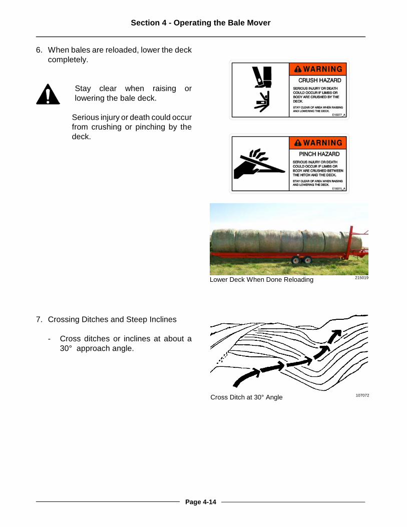
6. When bales are reloaded, lower the deckcompletely.
Stay clear when raising orlowering the bale deck.
Serious injury or death could occurfrom crushing or pinching by thedeck.
7. Crossing Ditches and Steep Inclines
- Cross ditches or inclines at about a30° approach angle.
Lower Deck When Done Reloading 215019
Cross Ditch at 30° Angle 107072
Page 4-14
Section 5 - Maintaining the Bale Mover
5.0 MAINTAINING THE BALE MOVER
Shutdown Procedure
For your safety and the safety ofothers, this procedure must befollowed before dismounting fromthe tractor for repairing, servicing,cleaning or lubricating the BaleMover.
Step 1: Reduce the engine speed to idle.Step 2: Fully lower bale lift arm.Step 3: Disengage hydraulic motors.Step 4: Set the tractor park brake.Step 5: Shut off tractor engine and remove
the key.Step 6: Relieve hydraulic pressure and
disconnect hydraulic hoses.
LubricationLubricate all grease fittings with a qualitylithium complex, extreme pressure NLGIGrade 2 grease.
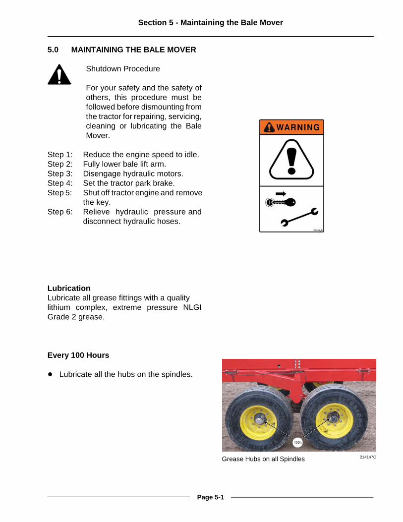
Every 100 Hours
! Lubricate all the hubs on the spindles.
Grease Hubs on all Spindles 214147C
Page 5-1

Section 5 - Maintaining the Bale Mover
! Lubricate the chains with a quality chainoil.
Chain Adjustment Procedure
Check the tension on the 2 rail chains.
- The chain can be seen in the sighthole (1) that is in the side of each rail.
- The chain should be in line with theimage of the chain that is on the decal(1) at the sight hole.
Lubricate the Bale Chains 216035
Check the Tension of All the Chains 211061
Page 5-2

Section 5 - Maintaining the Bale Mover
To adjust the chain tension:
- Loosen the clamping nuts (1) on themotor mount plate.
- Loosen the nut (2) at the end of thethreaded rod on the motor mount.
- Adjust the chain tension by turning theinside nut (3) until the chain is in linewith the image of the chain on thedecal at the sight hole
- Tighten the nut (2) at the end of thethreaded rod to secure the tensionsetting.
- Tighten the clamping nuts (1) on themotor mount plate.
Visually Inspect Hydraulic Hoses/Fittings
Shut down the machine and replace thehydraulic hose assembly if any of thefollowing conditions exist:
- Fitting slippage on hose.- Damaged, cracked, cut or abraded
cover (any reinforcement exposed).- Hard, stiff, heat cracked or charred
hose.- Cracked, damaged or badly corroded
fittings.- Leaks at fitting or in hose.- Kinked, crushed, flattened or twisted
hose.- Blistered, soft, degraded or loose
cover.
Adjust the Chain Tension 215024C
Page 5-3

Section 5 - Maintaining the Bale Mover
Tire Changing Procedure
Before beginning, make sure thetractor is turned off and theparking brake is set.
Securely block the Bale Moverbefore any work is done around orunder the machine.
Relieve hydraulic pressure anddisconnect the hydraulic hoses.
1. Hitch the Bale Mover to the tractor.
2. Block the Bale Mover tires on theopposite side to prevent movement of theBale Mover.
3. Place a jack under the spindle tube of thetire to be changed.
4. Jack for sufficient clearance to removethe tire and put the new tire in place.
5. Fasten the tire.
Tire Pressure
Keep tires properly inflated to 52 psi (358kPa). Tire damage may occur if tires areunder inflated.
Jack Under Spindle Tube to Change Tire 215023C
Page 5-4

Section 6 - Storing the Bale Mover
6.0 STORING THE BALE MOVER
1. Clean all the debris off the Bale Mover.
2. Lubricate all Bale Mover grease points(See Section 5).
3. Lubricate the bale chains to keep themfrom weather exposure.
4. Tighten all bolts to the recommendedtorque.
5. Check the Bale Mover for worn anddamaged parts. Replace as needed.
6. Touch-up the paint to prevent rusting.
7. Park the Bale Mover on level ground.
8. Lower the Bale Mover deck to be fullyresting on the frame.
Stay clear of deck when raising orlowering.
There is a crushing hazard if limbsor body is placed between thedeck and ground or surroundingobjects when the deck is raised orlowered.
Park on Level Ground 216038
Lower Deck onto the Frame 215035
Page 6-1

Section 6 - Storing the Bale Mover
9. Lower the lift arm to the ground.
Stand clear of the bale lift arm.
The moving lift arm can causeserious injury or death.Never stand under lift arms whenlowering or raising.Do not allow people near the liftarms when being moved.
- The lift arm should be lowered duringlong periods of storage so that thecylinder is in the retracted position.The retracted position will prevent therod from being exposed to theelements.
10. Raise the hitch until the weight issupported by the jack.
- Remove the jack from the storageposition and place it onto the hitch.
- Pin the jack in place.
- Ensure that the jack is resting on solidlevel ground or resting on a woodblock.
Lower the Lift Arm 215056M
Raise the Hitch with the Jack 214143
Page 6-2

Section 6 - Storing the Bale Mover
Oil the Chains to Prevent Weathering 214146
11. Oil the bale chains with a rustinhibiting oil or coating to preventweathering.
12. Disconnect the hitch from the tractor.
13. Relieve the pressure on the hydraulichoses and disconnect them.
14. Disconnect the electrical connections.
15. Remove the switch and cable from thetractor cab. Store in a dry place.
16. Secure the hydraulic hoses andelectrical connectors to the hoseholder (1) on the hitch to keep themoff the ground and clean.
Disconnect Hydraulics and Lighting 201199
Hydraulic Hoses and Electrical in Holder 215037C
Page 6-3

Section 6 - Storing the Bale Mover
This Page Left Blank
Page 6-4

Section 7 - Troubleshooting
7.0 TROUBLESHOOTING
Lift Arm
Symptom Problem Solution
Lift Arm Not Lifting Control Switch Place the control switch tothe “right” or “center”position.
Check the wiring to thehydraulic block for power tothe solenoid.
Hydraulics Check the hydraulicconnections to the hydraulicblock and the lift cylinder.
Solenoid on Hydraulic Block Check for power to thesolenoid on the hydraulicblock.
Arm Not Lowering When inAutomatic Bale AdvanceMode
Pilot Check Valve If the pilot line to the checkvalve is blocked it willprevent the fluid fromescaping the cylinder.
Chains
Symptom Problem Solution
Chains Do Not Move -Manual Mode
Control Switch Place the control switch tothe "left" or “center” position.
Check the wiring to thehydraulic block for power tothe solenoid.
Hydraulics Check the hydraulicconnections to the valveblock and the motors.
Page 7-1

Section 7 - Troubleshooting
Symptom Problem Solution
Chain Comes off the Roller Chain Tension Adjust the chain tension sothe chain is in line with theimage of the chain that is onthe decal at the sight hole.See “Chain AdjustmentProcedure” in Section 5.
Automatic Bale Advance Mode
Symptom Problem Solution
Chains Do Not Advance Control Switch Place the control switch tothe “right” position.
Check the wiring to thehydraulic block for power tothe solenoid.
Chains Do Not AdvanceEnough
Lift Arm Not Fully Raised Raise the lift arm to the fullyupright position whenloading a bale. The oil thatmoves the chain motorscomes from the lift cylinderas the arm is lowered.
Adjustment at Valve Block Turn the adjustment valve atthe valve block for morechain advance.
Chains Advance Too Far Adjustment at Valve Block Turn the adjustment valve atthe valve block for lesschain advance.
Page 7-2

Section 7 - Troubleshooting
Deck Lift
Symptom Problem Solution
Too much weight at the frontof the deck rails
Move bales on the railstoward the rear of themachine.
Deck Not Lifting Control Switch Place the control switch tothe "left" position.
Check the wiring to thehydraulic block for power tothe solenoid.
Solenoid on Hydraulic Block Check for power to thesolenoid on the hydraulicblock.
Hydraulics Check the hydraulicconnections to the hydraulicblock and the lift cylinder.
Page 7-3

Section 7 - Troubleshooting
This Page Left Blank
Page 7-4

Specifications
BALE MOVER SPECIFICATIONS
BM607 BM605
Weight (Unloaded) 5826 lb (2645 kg) 5272 lb (2393 kg)
Tongue Weight (unloaded) 1350 lb (613 kg) 1372 lb (623 kg)
Tongue Weight (loaded) 2283 lb (1036 kg) 2255 lb (1024 kg)
Tongue Weight (partially loaded) 4229 lb (1920 kg) 3152 lb (1431 kg)
Total Length 44' 1" (13.43 m) 33' 5 1/4" (10.19 m)
Deck Length 37' 4 1/2" (11.39 m) 26' 8 3/4" (8.14 m)
Total Width 8' 4 1/4" (2.54 m) 8' 4 1/4" (2.54 m)
Total Width - with axle extension 9' 0" (2.74 m) 9' 0" (2.74 m)
Deck Width 44” (1.1 m) 44" (1.1 m)
Total Height (Max) 13' 1 3/4" (4.0 m) 13' 1 3/4" (4.0 m)
Deck Height 3' 4 3/4" (1.03 m) 3' 4 3/4" (1.03 m)
Ground Clearance 13½” (342 mm) 13½" (342 mm)
Maximum Capacity Seven balesTotal bale weight -11353 lb (5150 kg)
Five balesTotal bale weight -12062 lb (5471 kg)
Tires IF280/70R15 Farm Radial
Horsepower Required 100 hp (74.5 kW)
Hydraulic Outlets 2
Hydraulic Pressure 2,500 psi (17,237 KPa)
Page 1

Specifications
This Page Left Blank
Page 2

Highline New Equipment Limited Warranty PolicyOne (1) Year / 12 Months - Parts and Labour
Highline Mfg. Ltd. (hereinafter "Highline") warrants this new product of Highline's manufacturer to be free fromdefects in material and workmanship, under normal use and service for one (1) full year after initial purchase/retailsale. Highline will warrant its product for one (1) year parts and labour, if performed by a qualified Dealer. ThisLimited Warranty shall apply only to complete machines of Highline's manufacture. Parts are covered by a separateLimited Warranty.
EQUIPMENT AND ACCESSORIES NOT OF HIGHLINE'S MANUFAC TURE ARE WARRANTED ONLY TO THEEXTENT OF THE ORIGINAL MANUFACTURER'S WARRANTY AND SUBJECT TO THEIR ALLOWANCE TOHIGHLINE ONLY IF FOUND DEFECTIVE BY SUCH MANUFACTUR ER.
During the Limited Warranty period specified above, any defect in material or workmanship in any warranted itemof Highline Equipment not excluded below shall be repaired or replaced at Highline's option without charge by anyauthorized independent Highline Dealer. An authorized Dealer must make the warranty repair or replacement.Labour in accordance with Highline's labour reimbursement policy. Highline reserves the right to supplyremanufactured replacement parts as it deems appropriate.
RETAIL PURCHASER RESPONSIBILITYThis Limited Warranty requires proper maintenance and periodic inspections of the Equipment as indicated in theOperator's Manual furnished with each new Equipment. The cost of routine or required maintenance and servicesis the responsibility of the retail purchaser. The retail purchaser is required to keep documented evidence that theseservices were performed. This Highline New Equipment Limited Warranty may be subject to cancellation if the aboverequirements are not performed.
EXCLUSIONS AND LIMITATIONSThe warranties contained herein shall NOT APPLY TO:1. Any defect which was caused (in Highline's sole judgement) by other than normal use and service of the
Equipment, or by any of the following:a. accident b. misuse or negligence c. overloading d. of reasonable and proper maintenance e. improper repair or installation f. unsuitable storage g. non-Highline approved alteration or modification h. natural calamities i. vandalism j. parts or accessories installed on Equipment which were not manufactured or installed by Highline authorized
Dealersk. the elements l. collision or other accident.
2. Any Equipment whose identification numbers or marks have been altered or removed.3. Any Equipment which any of the required or recommended periodic inspection or services have been performed
using parts not manufactured or supplied by Highline or meeting Highline Specifications including, but withoutlimitation, lubricants (oil, grease), belt lacings, and hydraulic fluids.
4. Any Equipment used in demonstrations not performed by a Highline Dealer. Warranty will be at the discretionof Highline for all other demonstration warranty.
5. New Equipment delivered to the retail purchaser in which the warranty registration has not been completed andreturned to Highline within ten (10) days from the date of purchase.
6. Any defect that was caused (in Highline's sole judgement) by operation of the Equipment not abiding by standardoperating procedures outlined in the Operator's Manual.
7. Tire Limited Warranties and support are the responsibility of the respective product's manufacturer.8. Transportation costs, if any, of transporting to the Highline Dealer.9. In no event shall Highline's liability exceed the purchase price of the product.10. Highline shall not be liable to any person under any circumstances for any incidental or consequential damages
(including but not limited to, loss of profits, out of service time and damage to equipment which this equipmentmay be attached) occurring for any reason at any time.
11. Diagnostic and overtime labour premiums are not covered under this Limited Warranty Policy.
Rev 3.1

12. Depreciation damage caused by normal wear, lack of reasonable and proper maintenance, failure to followoperating instructions, misuse, and/or lack of proper protection during storage.
13. Accessory systems and electronics not of Highline's manufacture are warranted only to the extent of suchmanufacturer's respective Limited Warranty if any.
14. Wear items which are listed by product group below:
COMMON WEAR ITEMSRoller chain, sprockets, clutches, shear bolts, clutch components, chains, gearbox housings bolts/torqued parts,flails, feed roller belting, coupler chain, DRV couplers, bogie wheels, apron tines and hoses, blades and blade pans,blade bolts and nuts, skid shoes, chain guards, clutches and clutch components.
PARTS WARRANTYParts replaced in the warranty period will receive the balance of the one year New Equipment Limited Warranty.Replacement parts after the original machine warranty are warranted to be free from defects of material for ninety(90) days or the part will be repaired or replaced, without labour coverage for removal and reinstallation.
EXCLUSION OF WARRANTIESUNLESS OTHERWISE REQUIRED BY LAW, AND EXCEPT FOR THE WARRANTIES EXPRESSLY ANDSPECIFICALLY MADE HEREIN, HIGHLINE MAKES NO OTHER WARRANTIES, AND ANY POSSIBLE LIABILITYOF HIGHLINE HEREIN UNDER IS IN LIEU OF ALL OTHER WARRANTIES, EXPRESS, IMPLIED, ORSTATUTORY, INCLUDING, BUT NOT LIMITED TO, ANY WARRANTIES OF MERCHANT ABILITY OR FITNESSFOR A PARTICULAR PURPOSE. HIGHLINE RESERVES THE RIGHT TO MODIFY, ALTER AND IMPROVE ANYPRODUCT WITHOUT INCURRING ANY OBLIGATION TO REPLACE ANY PRODUCT PREVIOUSLY SOLD WITHSUCH MODIFICATION. NO PERSON IS AUTHORIZED TO GIVE ANY OTHER WARRANTY, OR TO ASSUMEANY ADDITIONAL OBLIGATION ON HIGHLINE'S BEHALF.
Rev 3.1