ce 4228 data communications and networking wide area networks
TRANSCRIPT

CE 4228DATA COMMUNICATIONS AND NETWORKINGWide Area Networks

WAN – Outline
• Circuit switching• Telephone switching network• Traffic• Signaling
• Access networks• Packet switching
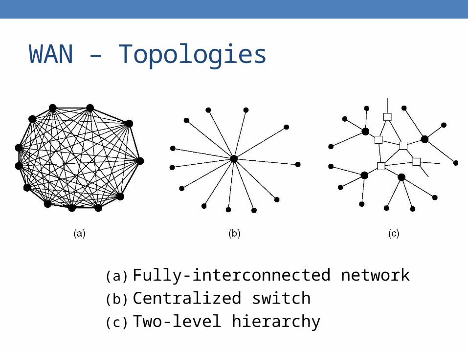
WAN – Topologies
(a) Fully-interconnected network
(b) Centralized switch
(c) Two-level hierarchy

WAN – Switching

Access network
Network
WAN – Switching
• A switch provides the network to a cluster of users• Telephone switch connects a local community
• A multiplexer connects two access networks• A high speed line connects two switches
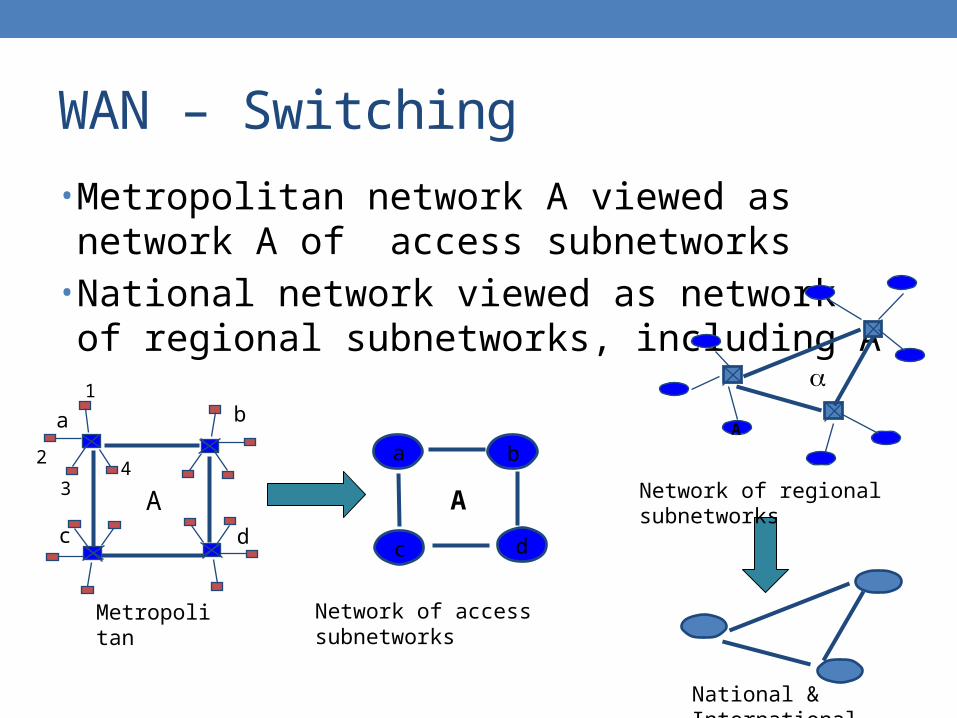
WAN – Switching
• Metropolitan network A viewed as network A of access subnetworks
• National network viewed as network of regional subnetworks, including A
Network of access subnetworks
A
dc
ba
Metropolitan
A
1
a
c
b
d
2
34
A
National & International
Network of regional subnetworks
WAN – Switching
• Long distance transmission is typically done over a network of switched nodes
• Nodes not concerned with content of data• End devices are stations
• Computer, terminal, phone, etc.
• A collection of nodes and connections is a communications network
• Data routed by being switched from node to node

WAN – Switching Nodes
• Nodes may connect to other nodes only, or to stations and other nodes
• Node to node links usually multiplexed• Network is usually partially connected
• Some redundant connections are desirable for reliability
• Two different switching technologies• Circuit switching• Packet switching

WAN – Switching Techniques
(a) Circuit switching
(b) Packet switching

Circuit Switching – Concept
• Dedicated communication path between two stations• Three phases
• Establish• Transfer• Disconnect
• Must have switching capacity and channel capacity to establish connection
• Must have intelligence to work out routing

Circuit Switching – Operation
• Connection set up takes time• Once connected, transfer is transparent with
guaranteed fixed rate• Inefficient
• Channel capacity dedicated for duration of connection• If no data, capacity wasted
• Developed for voice traffic• PSTN
• Public switched telephone network
• PBX• Private branch exchange

Circuit Switching – PSTN

Circuit Switching – Components
• Subscriber• Devices attached to
network
• Subscriber line• Local loop• Subscriber loop• Connection to network• Few km up to few tens of
km
• Exchange• Switching centers• End office
• Support subscribers
• Trunks• Branches between
exchanges• Multiplexed

Circuit Switching – Hierarchy
Regional Centers
Sectional Offices
Primary Offices
Toll Offices
End Offices
Local Loop
International Connections

LATA 1 LATA 2
Net 1
Net 2
1
2 3
4
5
A B
C D
Circuit Switching – Call Routing
• Local calls routed through local network• Local access and transport
area
• Long distance calls routed to long distance service provider

Circuit Switching – Establishment

Circuit Switching – Switch

Circuit Switching – Elements
• Digital switch• Provide transparent signal path between devices
• Network interface• Control unit
• Establish connections• Generally on demand• Handle and acknowledge requests• Determine if destination is free• Construct path
• Maintain connection• Disconnect

Circuit Switching – Space Switch
• Space division switching• Developed for analog environment• Separate physical paths• Crossbar switch
• Number of crosspoints grows as square of number of stations• C = N2
• Loss of crosspoint prevents connection• Inefficient use of crosspoints
• All stations connected, only a few crosspoints in use
• Non-blocking
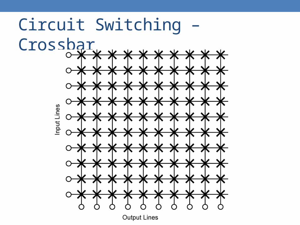
Circuit Switching – Crossbar

Circuit Switching – Multistage
• Reduced number of crosspoints• More than one path through network
• Increased reliability
• More complex control• May be blocking

Circuit Switching – Blocking
• Blocking• A network is unable to connect stations because all paths are
in use• A blocking network allows this• Used on voice systems
• Short duration calls
• Non-blocking• Permit all stations to connect in pairs at once• Used for some military or data connections• Multistage non-blocking switches often called Clos networks

Circuit Switching – 3-Stage

Circuit Switching – 3-Stage
Total crosspoints = kN +k(N/n)2 + kN = 2kN+ k(N/n)2
Number of paths, or maximum # connections = kN/n
nk
nk
nk
nk
N/n N/n
N/n N/n
N/n N/n
kn1
2
N/n
Ninputs
1
2
3 3
N/n
Noutputs
1
2
k
kn
kn
kn
… … …

Circuit Switching – Blocking
• The switch will block a new call when all the paths are used even through the destination is available
nk
nk
nk
N/n N/n
N/n N/n
kn1
N/n
Desiredinput
1
j m
N/n
Desiredoutput
1
kn
kn
n−1
N/n N/nn
N/n N/n2n−2
n−1busy
n−1busy
…… …
…
Free path Free pathN/n N/n2n−1

Circuit Switching – Non-Blocking
• The larger the k, the lower the blocking probability, but the more costly the switch
• If k = (n−1)+(n−1)+1 = 2n−1, the switch is strictly nonblocking
• Total nonblocking crosspoints = 2kN+ k(N/n)2 = (2n−1)[2N+(N/n)2]
• Minimum crosspoints = 4N[√(2N)−1]

Circuit Switching – Non-Blocking
Number of lines Number of crosspoints for
three-stage switch Number of crosspoints for
single-stage switch
128 7,680 16,256
512 63,488 261,632
2,048 516,096 4.2 million
8,192 4.2 million 67 million
32,768 33 million 1 billion
131,072 268 million 17 billion

Circuit Switching – Time Switch
• Time division switching• Use digital time
division techniques to set up and maintain virtual circuits
• Partition low speed bit stream into pieces that share higher speed stream
B0 B1 B2 B3 B4 B5 B6 B7 B8 B9
Time SlotInterchanger
B3 B5 B8 B0 B9 B1 B7 B6 B2 B4
3
5
8
0
9
1
7
6
2
4
0
1
2
3
4
5
6
7
8
9
Circuit Switching – Networks
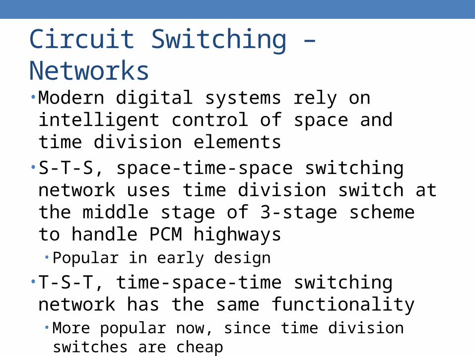
• Modern digital systems rely on intelligent control of space and time division elements
• S-T-S, space-time-space switching network uses time division switch at the middle stage of 3-stage scheme to handle PCM highways• Popular in early design
• T-S-T, time-space-time switching network has the same functionality• More popular now, since time division switches are cheap

Circuit Switching – TST Switches
• Very compact design• Fewer lines because of TDM• Less space because of time-shared crossbar• Interconnection pattern of space switch is reconfigured every
time slot
nk
nk
nk
nk
N/n N/nTime-sharedspace switch
kn1
2
N/n
N inputs
1
2
3 3
N/n
N outputs
TDMn slots
n slots
n slots
n slots
kn
kn
kn
TDMk slots
TDMk slots
Time stage Time stageSpace stage
… …
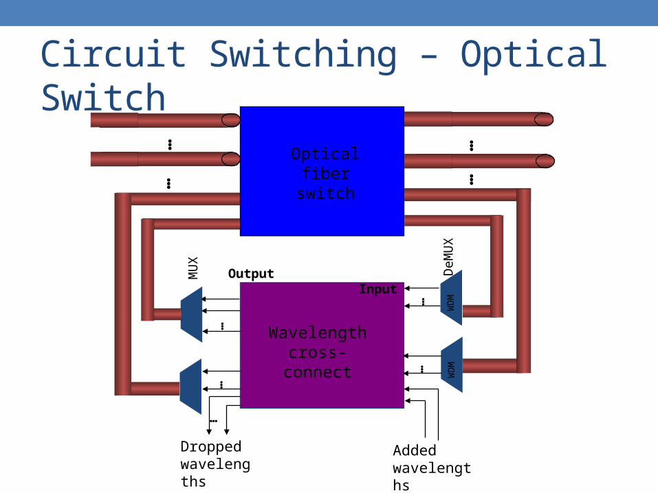
Circuit Switching – Optical Switch
Optical fiber switch
… …
Wavelength cross-connect
……W
DM
WD
M WD
M
Output InputMU
X
DeM
UX
Added wavelengths
Dropped wavelengths
…
…
…
……
WD
M

Circuit Switching – Optical Switch
• Pure optical switching• Light-in, light-out, without optical-to-electronic conversion
• Space switching theory can be used to design optical switches
• MEMs and electro-optic switching devices• Wavelength switches
• Very interesting designs when space switching is combined with wavelength conversion devices

Circuit Switching – Availability
• Grade of service• Probability of loss call
• Determine availability of system• Usual designs have far less outgoing channels than
incoming channels• A connection request will be blocked or denied if the
network has no idle circuit available• A user arriving at the high speed lab leaves whenever he finds
all the workstations are occupied

1
2
3
4
5
6
7
Tru
nk n
umbe
r
active active
active
active active
active
active active
active
active
Circuit Switching – Traffic
All trunks busy, new call requests blockedN(t)
t
Number of busy trunks

Circuit Switching – Traffic

Circuit Switching – Traffic
• The total traffic volume of one hour• Unit in Erlang, represents the continuous use of one
voice path• 1 Erlang = 1 hour of call
• Used to work out how many lines are required between a telephone system and a central office, PSTN exchange lines, or between multiple network locations

Circuit Switching – Traffic
• Suppose• m circuits or m channels available• The time interval between two successive connection
requests is exponentially distributed with mean 1/ seconds• The length of a connection is exponentially distributed with
mean 1/ seconds
• The total traffic is / Erlangs• Average utilization = (1−Pb)(/)/m

Circuit Switching – Erlang-B
• This formula is widely used• Trunking theory• Traffic engineering• Multiple server/processor
systems
• Sizing and capacity planning• Computer and communication
networks• Cellular system• Modem pool• Customer service centers• 191 help centers• Etc.
• Calculators or charts available online
m
n
n
m
b
n
mP
0
!/)/(
!/)/(

Circuit Switching – Erlang-B
• To achieve 1% blocking probability• Traffic of 5 Erlangs requires 11 trunks• Traffic of 10 Erlangs requires 18 trunks

Signaling – Control Functions
• Audible communication with subscriber• Transmission of dialed number• Call-cannot-be-completed indication• Call-ended indication• Signal to ring phone• Billing info• Equipment and trunk status info• Diagnostic info• Control of specialist equipment

Signaling – Telephone Call
• User requests connection• Network signaling establishes
connection• Speakers converse• User(s) hang up• Network releases connection
resources
Signal
Source
Signal
Release
Signal
Destination
Goahead Message

Signaling – Control Sequence
• Both phones on hook• Subscriber lifts receiver
• Off hook
• End office switch signaled• Switch responds with dial tone• Caller dials number• If target not busy, send ringer signal to target
subscriber

Signaling – Control Sequence
• Feedback to caller• Ringing tone• Busy signal
• Target accepts call by lifting receiver• Switch terminates ringing signal and ringing tone• Switch establishes connection• Release connection when source subscriber hangs up

Signaling – DTMF
Hz 1209 1336 1477
697 1 2 3
770 4 5 6
852 7 8 9
941 * 0 #
• Dual-tone multi-frequency• Send each digit by means
of a combination of two frequencies
• Each frequency is not harmonically related• Reduce the risk of signal
imitation

Signaling – Location
• Subscriber to network• Depend on subscriber device and switch
• Within network• Management of subscriber calls and network• More complex

Signaling – Inchannel
• Use same channel for signaling and call• Require no additional transmission facilities
• Inband• Use same frequencies as voice signal• Can go anywhere a voice signal can• Impossible to set up a call on a faulty speech path

Signaling – Inchannel
• Out of band• Voice signals do not use full 4 kHz bandwidth• Narrow signal band within 4 kHz used for control• Can be sent whether or not voice signals are present• Need extra electronics• Slower signal rate because of narrow bandwidth
• Drawbacks• Limited transfer rate• Delay between entering address by dialing and connection• Overcome by use of common channel signaling

Signaling – Common Channel
• Control signals carried over paths independent of voice channel
• One control signal channel can carry signals for a number of subscriber channels
• Common control channel for these subscriber lines• Associated mode
• Common channel closely tracks interswitch trunks
• Disassociated mode• Additional nodes• Effectively two separate networks

Signaling

Signaling
• Common channel signaling modes

Signaling – Techniques

Signaling – SS7
• Signaling System number 7• Common channel signaling scheme• Optimized for 64k digital channel network• Call control, remote control, management and
maintenance• Reliable means of transfer of info in sequence• Will operate over analog and below 64k• Point to point terrestrial and satellite links

Signaling – SS7 Network Element
• SP• Signaling point• Any point in the network
capable of handling SS7 control message
• STP• Signal transfer point• A signaling point capable
of routing control messages
• Control plane• Responsible for
establishing and managing connections
• Information plane• Once a connection is set
up, info is transferred in the information plane

Signaling – SS7
• Transfer points

Signaling – SS7 Network
• STP capacities• Number of signaling links that can be handled• Message transfer time• Throughput capacity
• Network performance• Number of SPs• Signaling delays
• Availability and reliability• Ability of network to provide services in the face of STP
failures
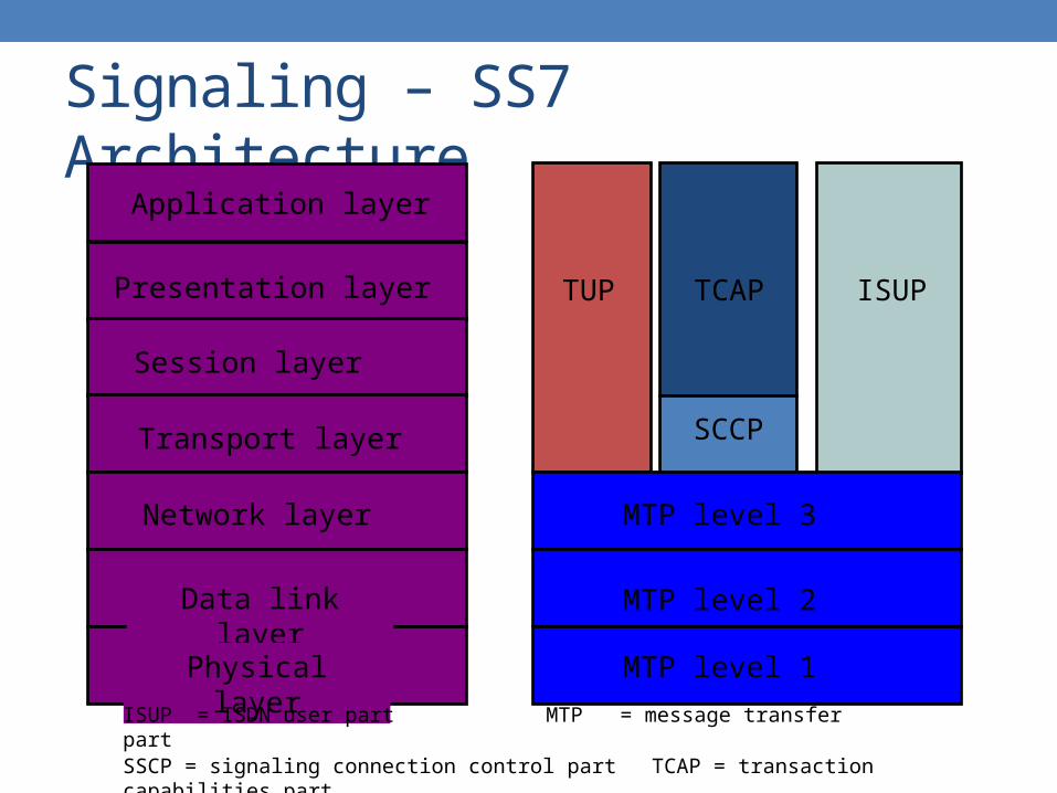
Signaling – SS7 ArchitectureApplication layer
Transport layer
Network layer
Data link layer
Physical layer
Presentation layer
Session layer
SCCP
MTP level 3
MTP level 2
MTP level 1
ISUPTCAPTUP
ISUP = ISDN user part MTP = message transfer partSSCP = signaling connection control part TCAP = transaction capabilities partTUP = telephone user part

Circuit Switching – Traditional

Circuit Switching – Softswitch

Circuit Switching – Softswitch
• General purpose computer running software to make it a smart phone switch
• Lower costs• Greater functionality
• Packetizing of digitized voice data• Allowing voice over IP

Circuit Switching – Softswitch
• Most complex part of telephone network switch is software controlling call process• Call routing• Call processing logic• Typically running on proprietary processor
• Separate call processing from hardware function of switch
• Physical switching done by media gateway• Call processing done by media gateway controller

Access Networks
• Modems, ADSL, and wireless• The use of both analog and digital transmissions for a
computer to computer call• Conversion is done by the modems and codecs
Access Networks – Telephone
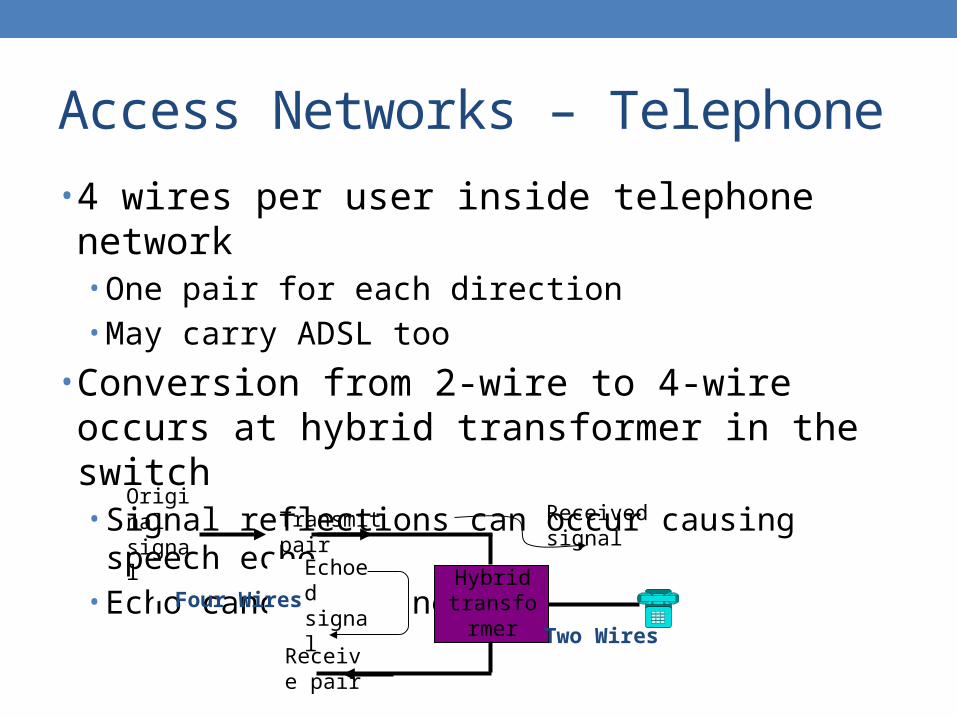
• 4 wires per user inside telephone network• One pair for each direction• May carry ADSL too
• Conversion from 2-wire to 4-wire occurs at hybrid transformer in the switch• Signal reflections can occur causing speech echo• Echo cancellers needed
Original signal
Hybrid transformer
Received signal
Echoed signal
Receive pair
Transmit pair
Two Wires
Four Wires
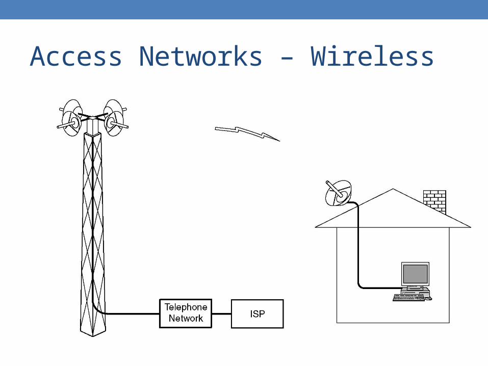
Access Networks – Wireless

Access Networks – Dial-Up Modem

Access Networks – Dial-Up Modem
• For digital data communications over analog PSTN• V.34 bis is capable of 33.6 kbps full duplex
• Shannon limit for the telephone system is about 35 kbps
• V.90 achieves a download speed of 56 kbps by eliminates analog transmission on one end, which reduces noise significantly• Upload speed still limited to 33.6 kbps• Make sense because there is usually more data downloaded
than uploaded

Access Networks – Dial-Up Modem
• 7 bits/sample is used in USA telephone system, so with 8000 samples/second, users are allowed for 56 kbps• In Europe, 8 bits/sample is used, so technically 64 kbps is
possible, but to get international agreement on a standard, 56 kbps was chosen
• V.92• New standard• 48 kbps upload speed• Reduce set up time by a half• Provide call waiting interruption

Access Networks – ADSL
• Asymmetrical digital subscriber line• Link between subscriber and network
• Local loop
• Use currently installed twisted pair cable• Can carry broader spectrum• 1 MHz or more• Must modify POTS by removing filters

Access Networks – ADSL Design
• Asymmetric• Greater capacity downstream than upstream
• Frequency division multiplexing• Lowest 25 kHz for POTS voice
• Plain old telephone service
• Use echo cancellation or FDM to give two bands• Use FDM within bands
• Range of 5.5 km

Access Networks – ADSL Bandwidth
• Bandwidth versus distance over category 3 UTP for DSL
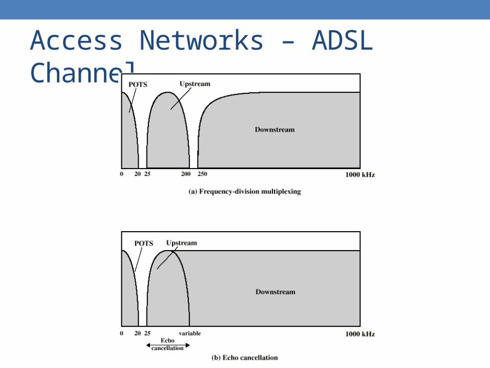
Access Networks – ADSL Channel

Access Networks – DMT
• Discrete multitone• Multiple carrier signals at different frequencies
• 4 kHz subchannels
• Send test signal and use subchannels with better signal to noise ratio
• 256 downstream subchannels at 4 kHz, each is capable of 60 kbps• 15.36 Mbps theoretical maximum bit rate• Impairments bring this down to 1.5 Mbps to 9 Mbps
• ADSL2+ goes up to 2.2 MHz

Access Networks – DMT Bit Allocation

Access Networks – DMT Transmitter

Access Networks – ADSL Arrangement

Access Networks – xDSL
• HDSL• High data rate DSL• Used in T-1/E-1• 2B1Q coding scheme• 2 Mbps over 2 TPs
• Symmetric
• SDSL• Single line DSL• Same as HDSL, but use on
one line• Echo cancellation
• VDSL• Very high data rate DSL• Based on ADSL• Much higher data rate, but
at a very short distance
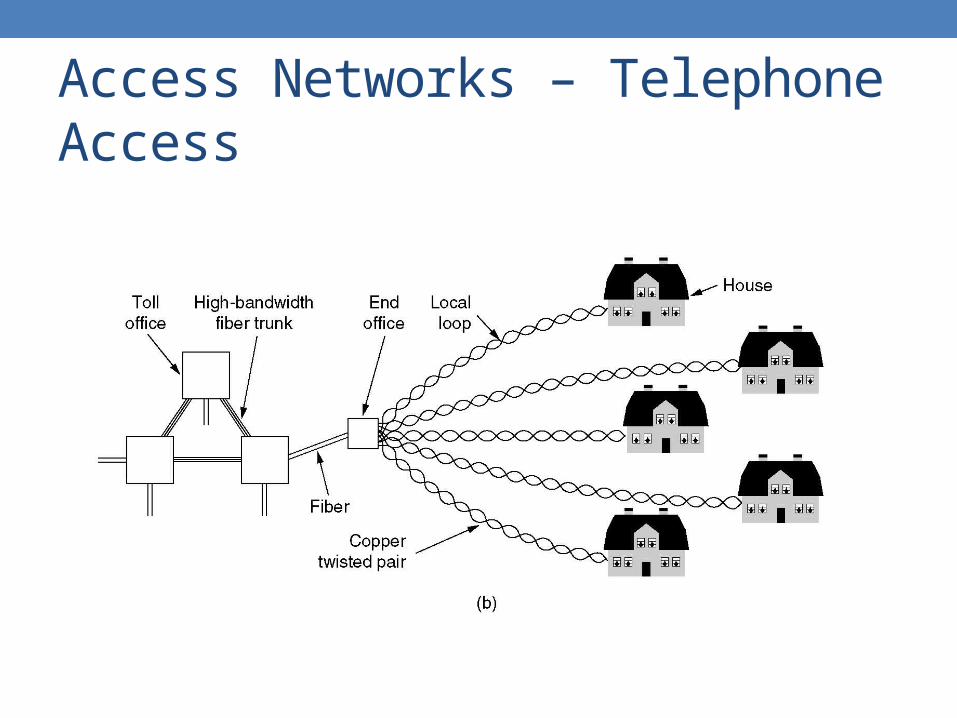
Access Networks – Telephone Access

Access Networks – Cable TV Access

Access Networks – Cable TV

Access Networks – Cable TV Spectrum
• Frequency allocation in a typical cable TV system used for Internet access

Access Networks – Cable Modem
• Two channels from cable TV provider dedicated to data transfer• One in each direction
• Each channel shared by number of subscribers• Scheme needed to allocate capacity• Statistical TDM

Access Networks – Statistical TDM
• In synchronous TDM many slots are wasted• Statistical TDM allocates time slots dynamically based
on demand• Multiplexer scans input lines and collects data until
frame full• Data rate on line lower than aggregate rates of input
lines• May cause problems during peak periods
• Buffer inputs• Keep buffer size to minimum to reduce delay

Access Networks
• Statistical TDM• Buffer size• Delay

Access Networks – Cable Modem
• Downstream• Cable scheduler delivers data in small packets• If more than one subscriber active, each gets fraction of
downstream capacity• May get 500 kbps to 1.5 Mbps
• Also used to allocate upstream time slots to subscribers
• Upstream• User requests timeslots on shared upstream channel
• Dedicated slots for this
• Headend scheduler sends back assignment of future time slots to subscriber

Access Networks – Cable Modem

Access Networks – Cable vs. ADSL
• Coaxial vs. twisted pair• Cable has higher maximum bandwidth
• ADSL providers give specific bandwidth• Each user has a dedicated connection
• Cable does not• Each user shares bandwidth• Unpredictable
• Security

Packet Switching – Concept
• Circuit switching designed for voice• Resources dedicated to a particular call• Much of the time a data connection is idle• Data rate is fixed• Both ends must operate at the same rate
• Need different switching technique to handle computer communications effectively

Packet Switching – Principles
• Data transmitted in small packets• Typically 1500 octets• Longer messages split into series of packets• Each packet contains a portion of user data plus some control
info
• Control info• Routing and addressing info
• Packets are received, stored briefly in buffer and past on to the next node• Store and forward

Packet Switching – Layout

Packet Switching – Store and Forward
Data 1 1
1 1
1 1
2 2
2 2
2 2Data
Tim
e

Packet Switching – Packet Size

Packet Switching – Advantages
• Line efficiency• Single node to node link can be shared by many packets over
time• Packets queued and transmitted as fast as possible
• Data rate conversion• Each station connects to the local node at its own speed• Nodes buffer data if required to equalize rates
• Packets are accepted even network is busy• Delivery may slow down
• Priorities can be used

Packet Switching – Packet Delay
• Total packet delay T = Tq + Tt + Tp
• Queueing delay and medium access time Tq
• Time the packet stays in the link interface buffer of the source node awaiting its turn to be transmitted
• The queueing/medium access time increases with the traffic load

Packet Switching – Service Type
• Connection-oriented service• Telephone system model• Set up a requested connection • Communicate without addressing• Must release the connection
• Connectionless service• Postal system model• Addressed messages are sent without a predetermined path• Messages are delivered independently, may take different
routes, and may arrive out of order

Packet Switching – Techniques
• Station breaks long message into packets• Packets sent one at a time to the network• Packets handled in two ways
• Datagram• Virtual circuit

Packet Switching – Datagram
• Connectionless approach• Each packet treated independently• Packets can take any practical route
• Packet-by-packet routing
• Packets may arrive out of order• Packets may go missing• Up to receiver to re-order packets and recover from
missing packets

Packet Switching
• Datagram

Packet Switching – Virtual Circuit
• Connection-oriented approach• Preplanned route established before any packets sent• Call request and call accept packets establish
connection• Each packet contains a virtual circuit identifier instead
of destination address• No routing decisions required for each packet• Clear request to drop circuit• Not a dedicated path
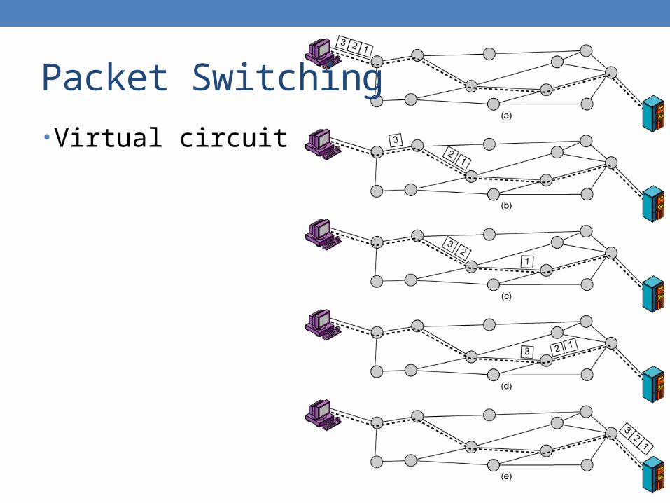
Packet Switching
• Virtual circuit

Packet Switching – Virtual Circuit

Packet Switching – Comparison
• Virtual circuit• Network can provide sequencing and error control• Packets are forwarded more quickly
• No routing decisions to make
• Less reliable• Loss of a node looses all circuits through that node
• Datagram• No call setup phase
• Better if few packets
• More flexible• Routing can be used to avoid congested parts of the network

Packet Switching – Comparison

Packet Switching – Comparison

Packet Switching – Comparison

Packet Switching – Timing

Packet Switching – WAN
• X.25• Frame relay• ATM• MPLS• All of the above are virtual-circuit based
• To provide some sort of guarantees

Packet Switching – Internet
• Internetwork• Network of networks
• IP• Internet Protocol• Connectionless
• TCP• Transmission Control Protocol• Connection-oriented
• On top of any protocol

Packet Switching – IP
• IP is designed with heterogeneity in mind• Must be simple, general, flexible, with no assumption of any
ability in each network• Hence, connectionless
• Provide a best-effort way to transport packets• Unreliable

Packet Switching – IPv4 Header
• Universal packet, all routers must recognize it

Packet Switching – IP Address
• IP address follows a hierarchical format• Allow efficient forwarding algorithm
• Since the packet format is universal, the address must be globally unique• 32-bit IPv4 addresses no longer enough• NAT is a temporary solution• Must migrate to IPv6

Packet Switching – IPv6 Header
• New version, being deployed

Packet Switching – IP Routing
• Process of finding path to forward packets• Hop-by-hop• Usually predetermined• Intra-domain routing
• Shortest path
• Inter-domain routing• Policy-based

Packet Switching – TCP
• IP provides unreliable, best-effort network service• Data-centric applications require reliable data delivery• Thus, TCP must be end-to-end, connection-oriented
transport protocol to provide reliable service• For applications that do not require reliability, the
connectionless UDP can be used instead• Real-time applications

Packet Switching – TCP/IP

WAN – Conclusion
• Circuit switching• Access networks• Packet switching• Internet