ce emc test report - leadmanreport no.: 41005003-e date of issue: d ecember 3, 2004 page 9 rev. 00...
TRANSCRIPT

Compliance Certification Services Inc. Report No.: 41005003-E Date of Issue: December 3, 2004
Note: This report shall not be reproduced except in full, without the written approval of Compliance Certification Services Inc. Ltd. This document may be altered or revised by Compliance Certification Services
Inc. personnel only, and shall be noted in the revision section of the document. Page 1 Total Page: 46
Rev. 00
CE EMC
TEST REPORT
For
Charger
Model: CC2425 24V/2.5A; CC2420 24V/2A; CC2415 24V/1.5A; CC2410 24V/1A; CC3615 36V/1.5A
Trade Name: COMING DATA CO., LTD.
Issued for
COMING DATA CO., LTD. No. 291, Hou Chu Wei St., Sanchung City,
Taipei Hsien, Taiwan
Issued by
Compliance Certification Services Inc. No. 81-1, Lane 210, Bade Rd., 2, Luchu Hsiang,
Taoyuan Hsien, (338) Taiwan TEL: 886-3-324-0332 FAX: 886-3-324-5235
Compliance Certification Services Inc. Report No.: 41005003-E Date of Issue: December 3, 2004
Page 2 Rev. 00
TABLE OF CONTENTS
1 TEST RESULT CERTIFICATION .............................................................................................................3
2 EUT DESCRIPTION....................................................................................................................................4
3.1 EUT SYSTEM OPERATION.............................................................................................................5 3.2 DECISION OF FINAL TEST MODE ................................................................................................5
3 SETUP OF EQUIPMENT UNDER TEST...................................................................................................6
4 FACILITIES AND ACCREDITATIONS....................................................................................................6
5.1 FACILITIES........................................................................................................................................6 5.2 LABORATORY ACCREDITATIONS AND LISTINGS ...................................................................7
5 INSTRUMENT AND CALIBRATION.......................................................................................................8
6.1 MEASURING INSTRUMENT CALIBRATION...............................................................................8 6.2 TEST AND MEASUREMENT EQUIPMENT ..................................................................................8
6 TERMINAL VOLTAGE & DISTURBANCE PORWER EMISSION TEST...........................................11
7.1 LIMIT ...............................................................................................................................................11 7.2 PRELIMINARY TERMINAL VOLTAGE TEST.............................................................................12 7.3 TEST PROCEDURE OF DISTURBANCE POWER ......................................................................13 7.4 TEST RESULTS ...............................................................................................................................15
7 POWER HARMONICS TEST...................................................................................................................18
8 POWER VOLTAGE FLUCTUATION / FLICKER TEST .......................................................................20
9 ELECTROSTATIC DISCHARGE (ESD) IMMUNITY TEST.................................................................22
10 RADIATED ELECTROMAGNETIC FIELD IMMUNITY TEST ...........................................................24
11 FAST TRANSIENTS/BURST IMMUNITY TEST...................................................................................27
12 SURGE IMMUNITY TEST.......................................................................................................................29
13 CONDUCTED DISTURBANCE/INDUCED RADIO-FREQUENCY FIELD IMMUNITY TEST ........31
14 VOLTAGE DIPS / SHORT INTERRUPTIONS .......................................................................................33
APPENDIX I - PHOTOGRAPHS OF TEST SETUP ........................................................................................35
APPENDIX II – TEST RESULT OF EN 61000-3-2/-3 .....................................................................................43


Compliance Certification Services Inc. Report No.: 41005003-E Date of Issue: December 3, 2004
Page 4 Rev. 00
2 EUT DESCRIPTION
Product Charger
Trade Name COMING DATA CO., LTD.
Model CC2425 24V/2.5A; CC2420 24V/2A; CC2415 24V/1.5A; CC2410 24V/1A; CC3615 36V/1.5A
Housing Type Plastic
EUT Power Rating I/P: 220-240VAC O/P: See as below
AC Power Cord Type Unshielded, 1.5m (Non-detachable)
DC Power Cable Type Unshielded, 1.5m (Non-detachable) Note:
1. Different between of five model numbers (list on this report) are list as below:
Model No. Output Voltage Output CurrentCC2425 24V/2.5A 24V 2.5A CC2420 24V/2A 24V 2A CC2415 24V/1.5A 24V 1.5A CC2410 24V/1A 24V 1A CC3615 36V/1.5A 36V 1.5A

Compliance Certification Services Inc. Report No.: 41005003-E Date of Issue: December 3, 2004
Page 5 Rev. 00
3 TEST METHODOLOGY
3.1 EUT SYSTEM OPERATION
The EUT connected with resistive load at full load and half load mode, during all testing.
3.2 DECISION OF FINAL TEST MODE
1. The following test mode(s) were scanned during the preliminary test:
Mode 1 Full Load – CC2425 24V/2.5A
Mode 2 Full Load – CC2420 24V/2A
Mode 3 Full Load – CC3615 36V/1.5A
Mode 4 Half Load – CC2425 24V/2.5A
Mode 5 Power Line – CC2425 24V/2.5A
2. After the preliminary scan, the following test mode was found to produce the highest emission level.
Mode 1 for All test items. Mode 5 for Disturbance Power Emission test item only.
Then, the EUT configuration and cable configuration of the above highest emission mode was chosen for all final test items.

Compliance Certification Services Inc. Report No.: 41005003-E Date of Issue: December 3, 2004
Page 6 Rev. 00
4 SETUP OF EQUIPMENT UNDER TEST
Setup Diagram
See test photographs attached in Appendix 1 for the actual connections between EUT and support equipment.
Support Equipment
No. Equipment Model No. Serial No. FCC ID Trade Name
Data Cable Power Cord
1 Resistor Load N/A N/A N/A N/A N/A Unshielded, 0.1m x 2
Note: All the above equipment/cables were placed in worse case positions to maximize emission signals during emission test.
Grounding: Grounding was in accordance with the manufacturer’s requirements and conditions for the intended use.
5 FACILITIES AND ACCREDITATIONS
5.1 FACILITIES
All measurement facilities used to collect the measurement data are located at CCS Taiwan Linkou Lab at No. 81-1, Lane 210, Bade Rd., 2, Luchu Hsiang, Taoyuan Hsien, Taiwan. The measurement facilities are constructed in conformance with the requirements of CISPR 16-1, ANSI C63.4 and other equivalent standards.

Compliance Certification Services Inc. Report No.: 41005003-E Date of Issue: December 3, 2004
Page 7 Rev. 00
5.2 LABORATORY ACCREDITATIONS AND LISTINGS
The test facilities used to perform Electromagnetic compatibility tests are registered or accredited by the organizations listed in the following table which includes the recognized scope specifically. Country Agency Scope of Accreditation Logo
USA NVLAP
EN 55011, EN 55014-1, AS/NZS 1044, CNS 13783-1, EN 55022, CNS 13438, EN 61000-3-2, EN 61000-3-3, ANSI C63.4, FCC OST/MP-5, AS/NZS CISPR 22, IEC 61000-4-2, IEC 61000-4-3, IEC 61000-4-4, IEC 61000-4-5, IEC 61000-4-6, IEC 61000-4-8, IEC 61000-4-11
USA FCC 3/10 meter Open Area Test Sites to perform FCC Part 15/18 measurements
93105, 90471
Japan VCCI 3/10 meter Open Area Test Sites and conducted test sites to perform radiated/conducted measurements
R-393/1066/725/879/1868C-402/747/912
Norway NEMKO
EN 50081-1/2, EN 50082-1/2, IEC 61000-6-1/2, EN 50091-2, EN 50130-4, EN 55011, EN 55013, EN 55014-1/2, EN 55015, EN 55022, EN 55024, EN 61000-3-2/3, EN 61326-1, IEC 61000-4-2/3/4/5/6/8/11, EN 60601-1-2, EN 300 328-2, EN 300 422-2, EN 301 419-1, EN 301 489-01/03/07/08/09/17, EN 301 419-2/3, EN 300 454-2, EN 301 357-2
ELA 124a ELA 124b ELA 124c
Taiwan CNLA
EN 300 328-1, EN 300 328-2, EN 300 220-1, EN 300 220-2, EN 300 220-3, 47 CFR FCC Part 15 Subpart C, EN 61000-3-2, EN 61000-3-3, CNS 13439, CNS 13783-1, CNS 14115, CNS 13438, AS/NZS CISPR 22, CNS 13022-1, IEC 61000-4-2/3/4/5/6/8/11, CNS 13022-2/3
Taiwan BSMI CNS 13438, CNS 13783-1, CNS 13439, CNS 14115
SL2-IS-E-0014 / IN-E-0014 /A1-E-0014 /R1-E-0014 /R2-E-0014 /L1-E-0014
Canada Industry Canada RSS212, Issue 1
IC 3991-3 IC 3991-4
Note: No part of this report may be used to claim or imply product endorsement by CNLA, NVLAP or other government agency.

Compliance Certification Services Inc. Report No.: 41005003-E Date of Issue: December 3, 2004
Page 8 Rev. 00
6 INSTRUMENT AND CALIBRATION 6.1 MEASURING INSTRUMENT CALIBRATION The measuring equipment utilized to perform the tests documented in this report has been calibrated once a year or in accordance with the manufacturer's recommendations, and is traceable under the IEC 17025 to international or national standards. Equipment has been calibrated by accredited calibration laboratories.
6.2 TEST AND MEASUREMENT EQUIPMENT
The following list contains measurement equipment used for testing. The equipment conforms to the requirement of CISPR 16-1, ANSI C63.2 and other required standards.
Calibration of all test and measurement, including any accessories that may effect such calibration, is checked frequently to ensure the accuracy. Adjustments are made and correction factors are applied in accordance with the instructions contained in the respective manual.
Equipment Used for Emission Measurement
Terminal Voltage Test Site
Name of Equipment Manufacturer Model Serial Number Calibration Due
EMI Test Receiver R&S ESCS30 847793/012 12/19/2004
LISN R&S ESH3-Z5 848773/014 10/27/2005
LISN R&S ENV 4200 830326/016 02/28/2005 Note: The measurement uncertainty is less than +/- 2.83dB, which is evaluated as per the NAMAS NIS 81 and CISPR/A/291/CDV.
Disturbance Power Test Site
Name of Equipment Manufacturer Model Serial Number Calibration Due
EMI Test Receiver R&S ESCS30 847793/012 12/19/2004
Pre-Amplifier ADVANTEST BB525C N/A 07/14/2005
Spectrum Analyzer ADVANTEST R3261AN 31720234 N.C.R
Shielding Room C & C N/A N/A N.C.R
Clamp R&S MDS-21 847905/016 05/19/2005

Compliance Certification Services Inc. Report No.: 41005003-E Date of Issue: December 3, 2004
Page 9 Rev. 00
Power Harmonic & Voltage Fluctuation/Flicker Measurement (EN 61000-3-2&-3-3)
Name of Equipment Manufacturer Model Serial Number Calibration Due
HARMONICS SYSTEM EMC-PARTNER HARMONICS-10
00 094 11/04/2005
Equipment Used for Immunity Measurement
ESD Test Site (IEC 1000-4-2)
Name of Equipment Manufacturer Model Serial Number Calibration Due
ESD Generator EM TEST P30C 0603-01 08/01/2005
Radiated Electromagnetic Field Immunity Test Site (IEC 61000-4-3)
Name of Equipment Manufacturer Model Serial Number Calibration Due
S.G. R&S SMY02 100094 08/05/2005
Power Meter R&S NRVD 837794/029 08/06/2005
Power Sensor R&S URV5-Z2 835640/015 08/06/2005
Power Sensor R&S URV5-Z2 835640/016 08/06/2005
Power Amplifier ar 150W1000 300300 N.C.R
Fast Transients/Burst Test Site (IEC 1000-4-4)
Name of Equipment Manufacturer Model Serial Number Calibration Due
Fast Transients/Burst Generator
HAEFELY TRENCH PEFT- JUNIOR 583 333-117 08/25/2005
Surge Immunity Test Site (IEC/EN EN 61000-4-5)
Name of Equipment Manufacturer Model Serial Number Calibration Due
Surge Tester HAEFELY TRENCH PSUGER 4010 583 334-71 08/25/2005

Compliance Certification Services Inc. Report No.: 41005003-E Date of Issue: December 3, 2004
Page 10 Rev. 00
CS Test Site (IEC 1000-4-6)
Name of Equipment Manufacturer Model Serial Number Calibration Due
S.G. R&S SMY02 100094 08/05/2005
Power Meter R&S NRVD 837794/029 08/06/2005
Power Sensor R&S URV5-Z2 835640/015 08/06/2005
Power Sensor R&S URV5-Z2 835640/016 08/06/2005
Power Amplifier ar 500A100A 300299 N.C.R
CDN Lüthi 801-M3 1879 03/03/2005
CDN FRANKONIA CDN-M2 A3002010 08/06/2005
Voltage Dips/Short Interruption and Voltage Variation Immunity Test Site (IEC/EN 61000-4-11)
Name of Equipment Manufacturer Model Serial Number Calibration Due
Dips/Interruption and Variations Simulator
HAEFELY TRENCH PLINE 1610 080 344-05 04/06/2005

Compliance Certification Services Inc. Report No.: 41005003-E Date of Issue: December 3, 2004
Page 11 Rev. 00
7 TERMINAL VOLTAGE & DISTURBANCE PORWER EMISSION TEST
7.1 LIMIT
Maximum permissible level of Terminal Voltage
At Mains Terminal (dBuV)
At load and additional Terminal(dBuV) Frequency
(MHZ) Quasi-peak Average Quasi-peak Average
0.15 - 0.5 66 - 56 56 - 46 80 70
0.50 - 5.0 56 46 74 64
5.0 - 30.0 60 50 74 64
Note: The lower limit shall apply at the transition frequency.
Maximum permissible level of Disturbance Power
Maximum Disturbance Power Limit (dBpW) Frequency
(MHZ) Quasi-peak Average
30 – 300 45 - 55 35 - 45
Note: The lower limit shall apply at the transition frequency.

Compliance Certification Services Inc. Report No.: 41005003-E Date of Issue: December 3, 2004
Page 12 Rev. 00
7.2 PRELIMINARY TERMINAL VOLTAGE TEST
Procedure of Preliminary Test
The EUT was set up as per the test configuration to simulate typical usage per the user’s manual. When the EUT is a tabletop system, a wooden table with a height of 0.8 meters is used and is placed on the ground plane as per CISPR 14/ EN 55014 (see Test Facility for the dimensions of the ground plane used). When the EUT is a floor-standing equipment, it is placed on the ground plane which has a 3-12 mm non-conductive covering to insulate the EUT from the ground plane.
Support equipment, if needed, was placed as per CISPR 14/ EN 55014.
All I/O cables were positioned to simulate typical actual usage as per CISPR 14/ EN 55014.
The test equipment EUT installed received AC power, 230VAC/50Hz, through a Line Impedance Stabilization Network (LISN), which supplied power source and was grounded to the ground plane.
All support equipment received power from a second LISN.
The EUT test program was started. Emissions were measured on each current carrying line of the EUT using an EMI Test Receiver connected to the LISN powering the EUT.
The Receiver scanned from 150kHz to 30MHz for emissions in each of the test modes.
During the above scans, the emissions were maximized by cable manipulation.
The test mode(s) described in Item 3.2 were scanned during the preliminary test.
After the preliminary scan, we found the test mode described in Item 3.2 producing the highest emission level.
The EUT configuration and cable configuration of the above highest emission level were recorded for reference of the final test.
Procedure of Final Test
EUT and support equipment were set up on the test bench as per the configuration with highest emission level in the preliminary test.
A scan was taken on both power lines, Line 1 and Line 2, recording at least the six highest emissions. Emission frequency and amplitude were recorded into a computer in which correction factors were used to calculate the emission level and compare reading to the applicable limit. If EUT emission level was less –2dB to the Average limit in Q.P. mode, then the emission signal was re-checked using an Average detector.
The test data of the worst-case condition(s) was recorded.

Compliance Certification Services Inc. Report No.: 41005003-E Date of Issue: December 3, 2004
Page 13 Rev. 00
Data Sample:
Freq. (MHz)
Q.P. Raw
(dBuV)
AverageRaw
(dBuV)
Q.P. Limit
(dBuV)
AverageLimit
(dBuV)
Q.P. Margin
(dB)
Average Margin
(dB) Note
x.xx 43.95 --- 56.00 46.00 -12.05 --- L1
Freq. = Emission frequency in MHz Raw dBuV = Uncorrected Analyzer/Receiver reading + Insertion loss of LISN, if it > 0.5 dB Limit dBuV = Limit stated in standard Margin dB = Reading in reference to limit Note = Current carrying line of reading “---“ = The emission level complied with the Average limits, with at least 2dB margin
limits, so no further recheck.
Calculation Formula
Margin (dB) = RAW (dBuV) – Limit (dBuV)
7.3 TEST PROCEDURE OF DISTURBANCE POWER
Procedure of Preliminary Test
The EUT was set up as per the test configuration to simulate typical usage per the user’s manual. When the EUT is a tabletop system, a wooden turntable with a height of 0.8 meters is used which is placed on the ground plane. When the EUT is a floor-standing equipment, it is placed on the ground plane which has a 3-12 mm non-conductive covering to insulate the EUT from the ground plane.
Any lead connecting the main appliance to an auxiliary apparatus is disconnected if this does not affect the operation of the appliance, or is isolated by means of ferrite rings (or an absorbing clamp) close to the appliance.
The EUT received AC power source, 230VAC/50Hz, from the outlet socket under the turntable. All support equipment received power from another socket under the turntable.
The EUT was started. Emissions were scanned and measured using a receiver spectrum analyzer connected to the absorbing clamp.
The absorbing clamp is positioned for maximum indication at each test frequency (30MHz to 300MHz), that means is clamp moved along the main lead until the maximum emission value is found.
After the preliminary scan, we found the test mode described in Item 3.2 producing the highest emission level.
The EUT and cable configuration, antenna position, polarization and turntable position of the above highest emission level were recorded for the final test.

Compliance Certification Services Inc. Report No.: 41005003-E Date of Issue: December 3, 2004
Page 14 Rev. 00
Procedure of Final Test
EUT and support equipment were set up on the turntable as per the configuration with highest emission level in the preliminary test.
The receiver scanned from 30MHz to 300MHz. Emissions were scanned and measured to moving the absorbing clamp along the main lead until the maximum emission value is found.
Recorded at least the six highest emissions. Emission frequency, amplitude, were recorded in which correction factors were used to calculate the emission level and compare reading to the applicable limit, and only Q.P reading will record in this report.
The test data of the worst-case condition(s) was recorded.
Data Sample:
Freq. (MHz)
Corr’dFactor(dB)
QP Raw
(dBuV)
AVG Raw
(dBuV)
QP Corr’ddB(pW)
AVG Corr’ddB(pW)
QP Limit
dB(pW)
AVG Limit
dB(pW)
QP MargindB(pW)
AVG MargindB(pW)
xx.xx 1.80 30.90 --- 32.70 --- 45.20 35.20 -12.50 ---
Freq. = Emission frequency in MHz Corr’d Factor dB = Correction factors for Insertion loss Raw dBuV = Uncorrected Analyzer /Receiver reading Corr’d dB(pW) = Raw reading + Correction factors Limit dB(pW) = Limit stated in standard Margin dB(pW) = Reading in reference to limit “---” = The emission level complied with the Average limits, at
least 2dB margin, so no recheck anymore. P = Peak Reading Q = Quasi-peak Reading A = Average Reading
Calculation Formula
Q.P. Margin dB(pW) = Q.P. Corr’d dB(pW) – Q.P. Limits dB(pW) Q.P. Corr’d dB(pW) = Q.P. Raw (dBuV) + Corr’d Factor (dB)

Compliance Certification Services Inc. Report No.: 41005003-E Date of Issue: December 3, 2004
Page 15 Rev. 00
7.4 TEST RESULTS
Load And Additional Terminal Emission
Model: CC2425 24V/2.5A Test Mode: Mode 1
Temperature: 26°C Humidity: 63% RH
Tested by: Bill Cheng Test Results: Pass
(The chart below shows the highest readings taken from the final data)
L1 = Line One (Live Line) / L2 = Line Two (Neutral Line)
Note: “---” denotes the emission level was or more than 2dB below the Average limit, so no re-check anymore.
Q.P. AVG Q.P. AVG Q.P. AVGRaw Raw Limit Limit Margin Margin
(dBuV) (dBuV) (dBuV) (dBuV) (dB) (dB)0.152 57.79 47.20 65.89 55.89 -8.10 -8.69 L10.220 46.31 --- 62.82 52.82 -16.51 --- L10.538 37.01 --- 56.00 46.00 -18.99 --- L10.932 33.51 --- 56.00 46.00 -22.49 --- L11.497 30.79 --- 56.00 46.00 -25.21 --- L12.080 27.67 --- 56.00 46.00 -28.33 --- L13.240 35.64 --- 56.00 46.00 -20.36 --- L15.882 37.59 --- 60.00 50.00 -22.41 --- L19.937 39.60 --- 60.00 50.00 -20.40 --- L120.680 37.82 --- 60.00 50.00 -22.18 --- L127.493 39.71 --- 60.00 50.00 -20.29 --- L1
0.156 54.26 44.70 65.67 55.67 -11.41 -10.97 L20.230 35.22 --- 62.45 52.45 -27.23 --- L20.508 33.78 --- 56.00 46.00 -22.22 --- L20.985 33.08 --- 56.00 46.00 -22.92 --- L21.332 35.42 --- 56.00 46.00 -20.58 --- L21.905 33.92 --- 56.00 46.00 -22.08 --- L23.790 34.32 --- 56.00 46.00 -21.68 --- L25.638 38.46 --- 60.00 50.00 -21.54 --- L29.449 40.88 --- 60.00 50.00 -19.12 --- L222.672 37.69 --- 60.00 50.00 -22.31 --- L227.140 36.76 --- 60.00 50.00 -23.24 --- L2
Freq.(MHz) NOTE

Compliance Certification Services Inc. Report No.: 41005003-E Date of Issue: December 3, 2004
Page 16 Rev. 00
Disturbance Power Emission
Model: CC2425 24V/2.5A Test Mode: Mode 1
Temperature: 24°C Humidity: 63% RH
Tested by: Bill Cheng Test Results: Pass
(The chart below shows the highest readings taken from the final data)
Note: “---” denotes the emission level was or more than 2dB below the Average limit, so no re-check anymore.
Corr'd Q.P. AVG Q.P. AVG Q.P. AVG Q.P. AVGFactor Raw Raw Corr'd Corr'd Limit Limit Margin Margin(dB) (dBuV) (dBuV) dB(pW) dB(pW) dB(pW) dB(pW) dB(pW) dB(pW)
33.12 0.50 29.00 --- 29.50 --- 45.10 35.10 -15.60 ---39.62 -0.15 31.70 --- 31.55 --- 45.40 35.40 -13.85 ---45.00 1.30 31.00 --- 32.30 --- 45.60 35.60 -13.30 ---64.73 0.72 35.50 --- 36.22 16.90 46.30 36.30 -10.08 -19.4073.19 0.30 34.20 --- 34.50 --- 46.60 36.60 -12.10 ---78.53 0.85 32.20 --- 33.05 --- 46.80 36.80 -13.75 ---90.00 1.40 34.30 --- 35.70 15.70 47.20 37.20 -11.50 -21.5097.70 0.95 27.80 --- 28.75 --- 47.50 37.50 -18.75 ---154.10 0.23 22.60 --- 22.83 --- 49.60 39.60 -26.77 ---175.83 0.20 22.00 --- 22.20 --- 50.40 40.40 -28.20 ---220.00 0.80 22.40 --- 23.20 --- 52.00 42.00 -28.80 ---299.24 2.12 17.20 --- 19.32 --- 55.00 45.00 -35.68 ---
FREQ(MHz)

Compliance Certification Services Inc. Report No.: 41005003-E Date of Issue: December 3, 2004
Page 17 Rev. 00
Disturbance Power Emission
Model: CC2425 24V/2.5A Test Mode: Mode 5
Temperature: 24°C Humidity: 63% RH
Tested by: Bill Cheng Test Results: Pass
(The chart below shows the highest readings taken from the final data)
Note: “---” denotes the emission level was or more than 2dB below the Average limit, so no re-check anymore.
Corr'd Q.P. AVG Q.P. AVG Q.P. AVG Q.P. AVGFactor Raw Raw Corr'd Corr'd Limit Limit Margin Margin(dB) (dBuV) (dBuV) dB(pW) dB(pW) dB(pW) dB(pW) dB(pW) dB(pW)
30.20 0.80 23.20 --- 24.00 --- 45.00 35.00 -21.00 ---45.00 1.30 36.20 --- 37.50 14.90 45.60 35.60 -8.10 -20.7051.23 2.65 38.00 --- 40.65 18.20 45.80 35.80 -5.15 -17.6064.50 0.72 34.20 --- 34.92 15.00 46.30 36.30 -11.38 -21.3090.00 1.40 30.10 --- 31.50 --- 47.20 37.20 -15.70 ---97.88 0.95 32.30 --- 33.25 --- 47.50 37.50 -14.25 ---
103.33 0.71 36.50 --- 37.21 27.00 47.70 37.70 -10.49 -10.70149.57 0.25 24.30 --- 24.55 --- 49.40 39.40 -24.85 ---175.38 0.20 23.50 --- 23.70 --- 50.40 40.40 -26.70 ---220.00 0.80 23.20 --- 24.00 --- 52.00 42.00 -28.00 ---299.55 2.11 15.70 --- 17.81 --- 55.00 45.00 -37.19 ---
FREQ(MHz)

Compliance Certification Services Inc. Report No.: 41005003-E Date of Issue: December 3, 2004
Page 18 Rev. 00
8 POWER HARMONICS TEST
Port : AC mains
Basic Standard : EN 61000-3-2 (2000)
Limits : CLASS A ; CLASS B; CLASS C ; CLASS D
Tested by : Michael Chen
Temperature : 26°C
Humidity : 51% RH
Limit:
Limits for Class A equipment Limits for Class D equipment
Harmonics
Order
n
Max. permissible
harmonics current
A
Harmonics
Order
n
Max. permissible harmonics
current per watt mA/W
Max. permissible
harmonics current
A
Odd harmonics Odd Harmonics only
3 2.30 3 3.4 2.30
5 1.14 5 1.9 1.14
7 0.77 7 1.0 0.77
9 0.40 9 0.5 0.40
11 0.33 11 0.35 0.33
13 0.21 13 0.30 0.21
15<=n<=39 0.15x15/n 15<=n<=39 3.85/n 0.15x15/n
Even harmonics
2 1.08
4 0.43
6 0.30
8<=n<=40 0.23x8/n

Compliance Certification Services Inc. Report No.: 41005003-E Date of Issue: December 3, 2004
Page 19 Rev. 00
Block Diagram of Test Setup:
Test Procedure:
a. The EUT was placed on the top of a wooden table 0.8 meters above the ground and operated to produce the maximum harmonic components under normal operating conditions for each successive harmonic component in turn.
b. The correspondent test program of test instrument to measure the current harmonics emanated from EUT is chosen. The measure time shall be not less than the time necessary for the EUT to be exercised. Test Result : (See Appendix II for details)
PASS FAIL
Harmonics & Flicker
Analyzer +
Power Source EUT
Support Units
Power Cord
0.8m

Compliance Certification Services Inc. Report No.: 41005003-E Date of Issue: December 3, 2004
Page 20 Rev. 00
9 POWER VOLTAGE FLUCTUATION / FLICKER TEST
Port : AC mains
Basic Standard : EN 61000-3-3 (1995 + A1: 2001)
Limits : §5 of EN 61000-3-3
Tested by : Michael Chen
Temperature : 21°C
Humidity : 52% RH
Limit:
TEST ITEM LIMIT REMARK
Pst 1.0 Pst means short-term flicker indicator.
Plt 0.65 Plt means long-term flicker indicator.
Tdt (ms) 500 Tdt means maximum time that dt exceeds 3 %.
dmax (%) 4% dmax means maximum relative voltage change.
dc (%) 3.3% dc means relative steady-state voltage change
Block Diagram of Test Setup:
Harmonics & Flicker
Analyzer +
Power Source
EUT
Support Units
Power Cord
0.8m

Compliance Certification Services Inc. Report No.: 41005003-E Date of Issue: December 3, 2004
Page 21 Rev. 00
Test Procedure: a. The EUT was placed on the top of a wooden table 0.8 meters above the ground and
operated to produce the most unfavorable sequence of voltage changes under normal operating conditions.
b. During the flick measurement, the measure time shall include that part of whole operation cycle in which the EUT produce the most unfavorable sequence of voltage changes. The observation period for short-term flicker indicator is 10 minutes and the observation period for long-term flicker indicator is 2 hours.
Test Result: Test Parameter Measurement Value Limit Result
Pst 0.072 1.0 Pass
Plt 0.072 0.65 Pass
Tdt (ms) 0 500 Pass
dmax (%) 0% 4% Pass
dc (%) 0.03% 3.3% Pass

Compliance Certification Services Inc. Report No.: 41005003-E Date of Issue: December 3, 2004
Page 22 Rev. 00
10 ELECTROSTATIC DISCHARGE (ESD) IMMUNITY TEST
Port : Enclosure
Basic Standard : IEC 1000-4-2
Test Level : ± 8 kV (Air Discharge)
± 4 kV (Contact Discharge)
± 4 kV (Indirect Discharge)
Performance Criterion : B (Standard Required)
Tested by : Michael Chen
Temperature : 23oC
Humidity : 52% RH
Pressure : 1002mbar
Block Diagram of Test Setup: (The 470 k ohm resistors are installed per standard requirement.)
VCP
Ground Reference Plane
Wooden Table
Support units EUT
30 cm
470 kΩ
470 kΩ
HCP
0.5 mm Thick Insulator
470 kΩ
10 cm
0.8 m Wooden Table

Compliance Certification Services Inc. Report No.: 41005003-E Date of Issue: December 3, 2004
Page 23 Rev. 00
Test Procedure:
1. The EUT was located 0.1m minimum from all side of the HCP. 2. The support units were located 1.0m minimum away from the EUT, if any. 3. Selecting appropriate points of EUT for Contact/Air discharge and put a mark on EUT to
show tested points. 4. The following test condition was followed during the tests.
Note: As per IEC/EN 61000-4-2, two 470k bleed resistors cable is connected between the EUT and HCP during the test applicable for power ungrounded or battery operating unit only.
The electrostatic discharges were applied as follows: Amount of discharge Voltage Coupling Result (Pass/Fail)
≥ 10 Point ± 8 kV Air Discharge Pass
≥ 10 Point ± 4 kV Contact Discharge Pass
≥ 10 Point ± 4 kV Indirect Discharge HCP Pass
≥ 10 Point ± 4 kV Indirect Discharge VCP (Right) Pass
≥ 10 Point ± 4 kV Indirect Discharge VCP (Left) Pass
≥ 10 Point ± 4 kV Indirect Discharge VCP (Back) Pass
No any discharge events occurred on the test. Performance & Result:
Criteria A: The apparatus continues to operate as intended. No degradation of performance or loss of function is allowed below a performance level specified by the manufacturer, when the apparatus is used as intended. In some cases the performance level may be replaced by a permissible loss of performance.
Criteria B: The apparatus continues to operate as intended after the test. No degradation of performance or loss of function is allowed below a performance level specified by the manufacturer, when the apparatus is used as intended. In some cases the performance level may be replaced by a permissible loss of performance. During the test, degradation of performance is however allowed.
Criteria C: Temporary loss of function is allowed, provided the functions self recoverable or can be restored by the operation of controls.
PASS FAIL
Observation: No function degraded during the tests.

Compliance Certification Services Inc. Report No.: 41005003-E Date of Issue: December 3, 2004
Page 24 Rev. 00
11 RADIATED ELECTROMAGNETIC FIELD IMMUNITY TEST
Port : Enclosure
Basic Standard : IEC 61000-4-3
Requirements : 3 V/m / with 80% AM. 1kHz Modulation.
Performance Criterion : A (Standard Required)
Tested by : Michael Chen
Temperature : 24oC
Humidity : 59% RH
Pressure : 1002mbar
Block Diagram of Test Setup:
0.8m
Power Amp Signal Generator
EUT Monitoring by using a camera
Control Room
7x3x3
EUT & Support Units
PC Controller to control S.G. & PA as well as forward power
3 meter
1.5 meter

Compliance Certification Services Inc. Report No.: 41005003-E Date of Issue: December 3, 2004
Page 25 Rev. 00
Test Procedure: 1. The EUT was located at the edge of supporting table keep 3 meter away from transmitting
antenna, it just the calibrated square area of field uniformity. The support units were located outside of the uniformity area, but the cable(s) connected with EUT were exposed to the calibrated field as per IEC 61000-4-3.
2. Setting the testing parameters of RS test software per IEC 61000-4-3. 3. From the result of pre-test in step 4, choice the worst side of EUT for final test from 80
MHz to 1000 MHz at 1% steps. 4. Recording the test result in following table.
Test conditions:
Frequency Range : 80MHz-1000MHz Frequency Step : 1% of fundamental Dwell Time : 3 sec Range (MHz) Field Modulation Polarity Position (°) Result (Pass/Fail)
80-1000 3V/m Yes H 0 Pass 80-1000 3V/m Yes V 0 Pass 80-1000 3V/m Yes H 90 Pass 80-1000 3V/m Yes V 90 Pass 80-1000 3V/m Yes H 180 Pass 80-1000 3V/m Yes V 180 Pass 80-1000 3V/m Yes H 270 Pass 80-1000 3V/m Yes V 270 Pass

Compliance Certification Services Inc. Report No.: 41005003-E Date of Issue: December 3, 2004
Page 26 Rev. 00
Performance & Result:
Criteria A: The apparatus continues to operate as intended. No degradation of performance or loss of function is allowed below a performance level specified by the manufacturer, when the apparatus is used as intended. In some cases the performance level may be replaced by a permissible loss of performance.
Criteria B: The apparatus continues to operate as intended after the test. No degradation of performance or loss of function is allowed below a performance level specified by the manufacturer, when the apparatus is used as intended. In some cases the performance level may be replaced by a permissible loss of performance. During the test, degradation of performance is however allowed.
Criteria C: Temporary loss of function is allowed, provided the functions self recoverable or can be restored by the operation of controls.
PASS FAIL
Observation: No function degraded during the tests.
Compliance Certification Services Inc. Report No.: 41005003-E Date of Issue: December 3, 2004
Page 27 Rev. 00
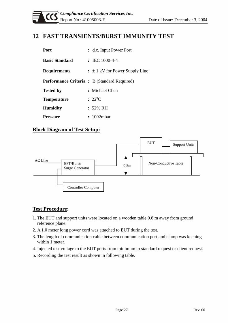
12 FAST TRANSIENTS/BURST IMMUNITY TEST
Port : d.c. Input Power Port
Basic Standard : IEC 1000-4-4
Requirements : ± 1 kV for Power Supply Line
Performance Criteria : B (Standard Required)
Tested by : Michael Chen
Temperature : 22oC
Humidity : 52% RH
Pressure : 1002mbar
Block Diagram of Test Setup:
Test Procedure:
1. The EUT and support units were located on a wooden table 0.8 m away from ground reference plane.
2. A 1.0 meter long power cord was attached to EUT during the test. 3. The length of communication cable between communication port and clamp was keeping
within 1 meter. 4. Injected test voltage to the EUT ports from minimum to standard request or client request. 5. Recording the test result as shown in following table.
Controller Computer
EFT/Burst/ Surge Generator
EUT Support Units
0.8m Non-Conductive Table AC Line

Compliance Certification Services Inc. Report No.: 41005003-E Date of Issue: December 3, 2004
Page 28 Rev. 00
Test conditions:
Impulse Frequency : 5kHz Tr/Th : 5/50ns Burst Duration : 15ms Burst Period : 3Hz
Inject Line Voltage kV Inject Method Result (Pass/Fail)
L ± 1 Direct Pass
N ± 1 Direct Pass
PE ± 1 Direct Pass
L + N ± 1 Direct Pass
L + PE ± 1 Direct Pass
N + PE ± 1 Direct Pass
L + N + PE ± 1 Direct Pass
Performance & Result:
Criteria A: The apparatus continues to operate as intended. No degradation of performance or loss of function is allowed below a performance level specified by the manufacturer, when the apparatus is used as intended. In some cases the performance level may be replaced by a permissible loss of performance.
Criteria B: The apparatus continues to operate as intended after the test. No degradation of performance or loss of function is allowed below a performance level specified by the manufacturer, when the apparatus is used as intended. In some cases the performance level may be replaced by a permissible loss of performance. During the test, degradation of performance is however allowed.
Criteria C: Temporary loss of function is allowed, provided the functions self recoverable or can be restored by the operation of controls.
PASS FAIL
Observation: No function degraded during the tests.

Compliance Certification Services Inc. Report No.: 41005003-E Date of Issue: December 3, 2004
Page 29 Rev. 00
13 SURGE IMMUNITY TEST
Port : Power Cord
Basic Standard : IEC 61000-4-5
Requirements : ± 1 kV (Line to Line)
± 2 kV (Line to Ground)
Performance Criteria : B (Standard Required)
Tested by : Michael Chen
Temperature : 22oC
Humidity : 51% RH
Pressure : 1002mbar
Block Diagram of Test Setup:
Test Procedure: 1. The EUT and support units were located on a wooden table 0.8 m away from ground floor. 2. Injected test voltage to the EUT ports from minimum to standard request or client request. 3. Recording the test result as shown in following table.
Surge Immunity Test
Controller Computer
EUT &
Support Units
0.8m
To AC Source

Compliance Certification Services Inc. Report No.: 41005003-E Date of Issue: December 3, 2004
Page 30 Rev. 00
Test conditions:
Voltage Waveform : 1.2/50 us Current Waveform : 8/20 us Polarity : Positive/Negative Phase angle : 0o, 90o, 270o Number of Test : 5
Coupling Line Voltage (kV) Polarity Coupling Method
Result (Pass/Fail)
L1-L2 1 Positive Capacitive Pass
L1-PE 2 Positive Capacitive Pass
L2-PE 2 Positive Capacitive Pass
L1-L2 1 Negative Capacitive Pass
L1-PE 2 Negative Capacitive Pass
L2-PE 2 Negative Capacitive Pass
Performance & Result:
Criteria A: The apparatus continues to operate as intended. No degradation of performance or loss of function is allowed below a performance level specified by the manufacturer, when the apparatus is used as intended. In some cases the performance level may be replaced by a permissible loss of performance.
Criteria B: The apparatus continues to operate as intended after the test. No degradation of performance or loss of function is allowed below a performance level specified by the manufacturer, when the apparatus is used as intended. In some cases the performance level may be replaced by a permissible loss of performance. During the test, degradation of performance is however allowed.
Criteria C: Temporary loss of function is allowed, provided the functions self recoverable or can be restored by the operation of controls.
PASS FAIL
Observation: No function degraded during the tests.

Compliance Certification Services Inc. Report No.: 41005003-E Date of Issue: December 3, 2004
Page 31 Rev. 00
CDN
EUT and Support units Power
AmplifierPC
Controller
Ground Reference Plane
10 cm isolation supporter
0.1m< L <0.3m
14 CONDUCTED DISTURBANCE/INDUCED RADIO-FREQUENCY FIELD IMMUNITY TEST
Port : d.c. Input Power Port
Basic Standard : IEC 1000-4-6
Requirements : 3 V with 80% AM. 1kHz Modulation.
Injection Method : CDN-M3 for Power Cord
Performance Criterion : A (Standard Required)
Tested by : Michael Chen
Temperature : 24oC
Humidity : 59% RH
Pressure : 1002mbar
Block Diagram of Test Setup:
Test Procedure: 1. The EUT and support units were located at a ground reference plane with the interposition
of a 0.1 m thickness insulating support and the CDN was located on GRP directly. 2. Setting the testing parameters of CS test software as per IEC 61000-4-6. 3. Recording the test result in following table.

Compliance Certification Services Inc. Report No.: 41005003-E Date of Issue: December 3, 2004
Page 32 Rev. 00
Test conditions:
Frequency Range : 0.15MHz-80MHz Frequency Step : 1% of fundamental Dwell Time : 3 sec
Range (MHz) Field Modulation Result (Pass/Fail)
0.15-80 3V Yes Pass
Performance & Result:
Criteria A: The apparatus continues to operate as intended. No degradation of performance or loss of function is allowed below a performance level specified by the manufacturer, when the apparatus is used as intended. In some cases the performance level may be replaced by a permissible loss of performance.
Criteria B: The apparatus continues to operate as intended after the test. No degradation of performance or loss of function is allowed below a performance level specified by the manufacturer, when the apparatus is used as intended. In some cases the performance level may be replaced by a permissible loss of performance. During the test, degradation of performance is however allowed.
Criteria C: Temporary loss of function is allowed, provided the functions self recoverable or can be restored by the operation of controls.
PASS FAIL
Observation: No function degraded during the tests.

Compliance Certification Services Inc. Report No.: 41005003-E Date of Issue: December 3, 2004
Page 33 Rev. 00
15 VOLTAGE DIPS / SHORT INTERRUPTIONS
Port : AC mains
Basic Standard : IEC 61000-4-11
Requirement : PHASE ANGLE 0, 45, 90, 135, 180, 225, 270, 315 degrees Test Level
% UT Reduction
(%) Duration ( periods )
PerformanceCriteria
40 60 10 C Voltage
Dips 70 30 50 C
Test Level % UT
Reduction (%)
Duration ( periods )
PerformanceCriteria Voltage
Interceptions 0 >95 0.5 C
Test Interval : Min. 10 sec.
Tested by : George Kuo
Temperature : 23oC
Humidity : 50% RH
Pressure : 1002mbar
Block Diagram of Test Setup:
Test Procedure: 1. The EUT and support units were located on a wooden table, 0.8 m away from ground
floor. 2. Setting the parameter of tests and then Perform the test software of test simulator. 3. Conditions changes to occur at 0 degree crossover point of the voltage waveform. 4. Recording the test result in test record form.
Dips/Interruption and Variations
Simulator
Controller Computer
EUT &
Support Units
0.8m
To AC Source

Compliance Certification Services Inc. Report No.: 41005003-E Date of Issue: December 3, 2004
Page 34 Rev. 00
Test conditions
The duration with a sequence of three dips/interruptions with interval of 10 s minimum (Between each test event)
Voltage Dips:
Test Level % UT
Reduction (%)
Duration (periods) Observation
Meet Performance
Criteria
40 60 10 Normal A
70 30 50 Normal A Voltage Interruptions:
Test Level % UT
Reduction (%)
Duration (periods) Observation
Meet Performance
Criteria
0 100 0.5 EUT shut down, but can be auto recovered as the events disappear.
B
Normal: No any functions degrade during and after the test.
Performance & Result:
Criteria A: The apparatus continues to operate as intended. No degradation of performance or loss of function is allowed below a performance level specified by the manufacturer, when the apparatus is used as intended. In some cases the performance level may be replaced by a permissible loss of performance.
Criteria B: The apparatus continues to operate as intended after the test. No degradation of performance or loss of function is allowed below a performance level specified by the manufacturer, when the apparatus is used as intended. In some cases the performance level may be replaced by a permissible loss of performance. During the test, degradation of performance is however allowed.
Criteria C: Temporary loss of function is allowed, provided the functions self recoverable or can be restored by the operation of controls.
PASS FAIL

Compliance Certification Services Inc. Report No.: 41005003-E Date of Issue: December 3, 2004
Page 35 Rev. 00
APPENDIX I - PHOTOGRAPHS OF TEST SETUP
TERMINAL VOLTAGE EMISSION

Compliance Certification Services Inc. Report No.: 41005003-E Date of Issue: December 3, 2004
Page 36 Rev. 00
DISTURBANCE POWER EMISSION
Mode 1

Compliance Certification Services Inc. Report No.: 41005003-E Date of Issue: December 3, 2004
Page 37 Rev. 00
Mode 5

Compliance Certification Services Inc. Report No.: 41005003-E Date of Issue: December 3, 2004
Page 38 Rev. 00
POWER HARMONIC & VOLTAGE FLUCTUATION / FLICKER TEST

Compliance Certification Services Inc. Report No.: 41005003-E Date of Issue: December 3, 2004
Page 39 Rev. 00
ELECTROSTATIC DISCHARGE TEST

Compliance Certification Services Inc. Report No.: 41005003-E Date of Issue: December 3, 2004
Page 40 Rev. 00
RADIATED ELECTROMAGNETIC FIELD TEST
FAST TRANSIENTS/BURST TEST

Compliance Certification Services Inc. Report No.: 41005003-E Date of Issue: December 3, 2004
Page 41 Rev. 00
SURGE IMMUNITY TEST
CONDUCTED DISTURBANCE, INDUCED BY RADIO-FREQUENCY FIELDS TEST

Compliance Certification Services Inc. Report No.: 41005003-E Date of Issue: December 3, 2004
Page 42 Rev. 00
VOLTAGE DIPS / INTERRUPTION TEST

Compliance Certification Services Inc. Report No.: 41005003-E Date of Issue: December 3, 2004
Page 43 Rev. 00
APPENDIX II – TEST RESULT OF EN 61000-3-2/-3
Harmonic Emission - IEC 61000-3-2 , EN 61000-3-2 , (EN60555-2)
Comply: IEC 61000-3-2 Ed.2.1 :2001 (incl. Amd.14) - IEC 61000-4-7 Ed.1.0 :1991
NA
HARCS Setup File : unnamed
HARCS Report File : unnamed
Operator : Michael Chen
EUT : CHARGER
Model No. CC2425
Remarks TEMP:26 HUMD:51
Full Bar : Actual Values
Empty Bar : Maximum Values
Blue : Current , Green : Voltage , Red : Failed

Compliance Certification Services Inc. Report No.: 41005003-E Date of Issue: December 3, 2004
Page 44 Rev. 00
Measurement NA Date : 2004/11/30 PM 07:17: V3.15
File :
Operator : Michael Chen
EUT : CHARGER
Model No. CC2425
Remarks TEMP:26 HUMD:51
Urms = 230.1V Freq = 59.981 Range: 5 A
Irms = 0.559A Ipk = 2.317A cf = 4.144
P = 60.86W Pap = 128.6VA pf = 0.473
THDi = 87.9 % THDu = 0.10 % Class A
Test - Time : 5min ( 100 %)
Test completed, Result: PASSED
Order Freq. Imax Imax% Imax%L Limit Status
[Hz] [A] [%] [%] [A]
1 60 0.8997 160.92
2 120 0.0012 0.2183 0.1130 1.0800
3 180 0.2579 46.124 11.212 2.3000
4 240 0.0012 0.2183 0.2839 0.4300
5 300 0.2402 42.959 21.068 1.1400
6 360 0.0015 0.2729 0.5086 0.3000
7 420 0.2127 38.046 27.624 0.7700
8 480 0.0015 0.2729 0.6634 0.2300
9 540 0.1804 32.260 45.090 0.4000
10 600 0.0015 0.2729 0.8293 0.1840
11 660 0.1456 26.037 44.112 0.3300
12 720 0.0018 0.3275 1.1942 0.1533
13 780 0.1114 19.924 53.042 0.2100
14 840 0.0021 0.3821 1.6254 0.1314
15 900 0.0827 14.793 55.135 0.1500
16 960 0.0027 0.4913 2.3883 0.1150

Compliance Certification Services Inc. Report No.: 41005003-E Date of Issue: December 3, 2004
Page 45 Rev. 00
17 1020 0.0620 11.081 46.807 0.1324
18 1080 0.0034 0.6004 3.2840 0.1022
19 1140 0.0504 9.0065 42.521 0.1184
20 1200 0.0037 0.6550 3.9806 0.0920
21 1260 0.0461 8.2424 43.009 0.1071
22 1320 0.0040 0.7096 4.7435 0.0836
23 1380 0.0436 7.8057 44.610 0.0978
24 1440 0.0040 0.7096 5.1747 0.0767
25 1500 0.0409 7.3144 45.437 0.0900
26 1560 0.0037 0.6550 5.1747 0.0708
27 1620 0.0357 6.3865 42.847 0.0833
28 1680 0.0034 0.6004 5.1084 0.0657
29 1740 0.0293 5.2402 37.760 0.0776
30 1800 0.0031 0.5459 4.9757 0.0613
31 1860 0.0229 4.0939 31.535 0.0726
32 1920 0.0027 0.4913 4.7767 0.0575
33 1980 0.0183 3.2751 26.855 0.0682
34 2040 0.0027 0.4913 5.0752 0.0541
35 2100 0.0156 2.7838 24.211 0.0643
36 2160 0.0024 0.4367 4.7767 0.0511
37 2220 0.0150 2.6747 24.590 0.0608
38 2280 0.0024 0.4367 5.0420 0.0484
39 2340 0.0143 2.5655 24.862 0.0577
40 2400 0.0021 0.3821 4.6440 0.0460

Compliance Certification Services Inc. Report No.: 41005003-E Date of Issue: December 3, 2004
Page 46 Rev. 00
NA Date : 2004/11/30 PM 07:07: V3.15
File :
Operator : Michael Chen
EUT : CHARGER
Model No. CC2425
Remarks TEMP:21 HUMD:52
Urms = 230.1V Freq = 60.075 Range: 5 A
Irms = 0.547A Ipk = 2.236A cf = 4.089
P = 59.88W Pap = 125.8VA pf = 0.476
Test - Time : 1 x 10min = 10min ( 100 %)
LIN (Line Impedance Network) : SLIN 0.24ohm +j0.15ohm N:0.16ohm +j0.10ohm
Limits : Plt : 0.65 Pst : 1.00
dmax : 4.00 % dc : 3.30 %
dtLim: 3.30 % dt>Lim: 500ms
Test completed, Result: PASSED
Plt = 0.072
Pst dmax dc dt>Lim Fail
[%] [%] [ms]
1 0.072 0.000 0.030 0.000