ce master user manual for maxxum - minn kota motors
TRANSCRIPT

Feature InformationInstallationOperationAdjustmentsCautionsCircuit BreakerBattery ConnectionWiring DiagramPropeller ReplacementTrouble ShootingMaintenanceLimited Warranty
DescriptionPoseFonctionnementRéglagesPrudencesDisjoncteurBranchement de la batterieSchéma de câblageRemplacement de l’héliceDépannageEntretienGarantie limitée
pg. 2pg. 3pg. 4pg. 5-6pg. 7pg. 8pg. 9pg. 10pg. 11pg. 12pg. 12pg. 14
bowmount bowGuARD 360°® foot contRoL tRoLLInG motoR
motEuR DE P cHE à PéDALE DE commAnDE bowGuARD 360°® montAGE suR PRouE
CE Master User Manual for MAXXUM
NOTE: Do not return your Minn Kota motor to your retailer. Your retailer is not authorized to repair or replace this unit. You may obtain service by: • calling Minn Kota at 1-800-227-6433 or 1-507-345-4623;• returning your motor to the Minn Kota Factory Service Center; • sending or taking your motor--- to any Minn Kota authorized service center on enclosed list.Please include proof of purchase, serial number and purchase date for warranty service with any of the above options.
REMARQUE: Ne pas retourner le moteur Minn Kota au concessionnaire. Ce dernier n’est pas autorisé à le réparer ou à le remplacer. En cas de panne:• Contacter Minn Kota au 1-800-227-6433 ou au 1-507-345-4623;• Retourner le moteur à l’usine Minn Kota;• Ou à un centre de Minn Kota agréé de la liste suivante.Quelle que soit l’option, joindre la facture, mentionner le n° de série et la date d’achat pour bénéficier de la garantie.
PLEAsE tHoRouGHLy READ tHIs usER mAnuAL. foLLow ALL InstRuctIons AnD HEED ALL sAfEty & cAutIonARy notIcEs bELow. usE of tHIs motoR Is onLy PERmIttED foR PERsons tHAt HAvE READ AnD unDERstooD tHEsE usER InstRuctIons. mInoRs mAy usE tHIs motoR onLy unDER ADuLt suPERvIsIon.
LIsEz s’IL vous PLAît tout à fAIt cE mAnuEL D’utILIsAtEuR. suIvEz toutEs LEs InstRuctIons Et fAItEs AttEntIon à toutE LA sécuRIté Et Aux PRéAvIs D’AvERtIssEmEnt cI-DEssous. L’utILIsAtIon DE cE motEuR Est sEuLEmEnt PERmIsE PouR LEs PERsonnEs quI ont Lu Et ont com-PRIs cEs InstRuctIons D’utILIsAtEuR. LEs mInEuRs PEuvEnt utILIsER cE motEuR sEuLEmEnt DAns LA suPERvIsIon ADuLtE.
serial number numéro de série purchase datedate d’achat

fEA
tuR
E Info
Rm
AtIo
n
DEsc
RIPtIo
n
Lifetime warrantyflexible composite shaftGarantie à vieArbre composite souple
bowGuard 360°® breakaway ProtectionProtection bowGuard 360°®
mom/off/con switchcommande mom./
Arrêt/continu
Heel blockbutée du talon
Rugged Aluminum and High strength steel bracket
support d’aluminium robuste et d’acier de qualité supérieure
weedless wedge PropellerHélice anti-herbe weedless wedge
Permanent magnet motormoteur à aimant permanent
momentary switchcommande
Rotary speed controlmolette de réglage de
la vitesse
2
Specifications subject to change without notice.Ces caractéristiques peuvent faire l’objet de modifications sans préavis.
Depth collar Knobbouton du collier de profondeur
Lighted Direction IndicatorIndicateur de direction éclairé
In
stALLA
tIon
PosE
3
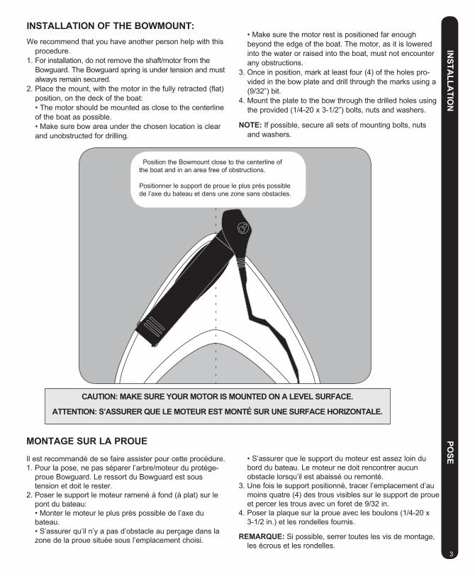
Position the Bowmount close to the centerline of the boat and in an area free of obstructions.
Positionner le support de proue le plus près possible de l’axe du bateau et dans une zone sans obstacles.
cAutIon: mAKE suRE youR motoR Is mountED on A LEvEL suRfAcE.
AttEntIon: s’AssuRER quE LE motEuR Est monté suR unE suRfAcE HoRIzontALE.
InstALLAtIon of tHE bowmount:We recommend that you have another person help with this
procedure.1. For installation, do not remove the shaft/motor from the
Bowguard. The Bowguard spring is under tension and must always remain secured.
2. Place the mount, with the motor in the fully retracted (flat) position, on the deck of the boat:
•Themotorshouldbemountedasclosetothecenterlineof the boat as possible.
•Makesurebowareaunderthechosenlocationisclearand unobstructed for drilling.
•Makesurethemotorrestispositionedfarenoughbeyond the edge of the boat. The motor, as it is lowered into the water or raised into the boat, must not encounter any obstructions.
3. Once in position, mark at least four (4) of the holes pro-vided in the bow plate and drill through the marks using a (9/32”) bit.
4. Mount the plate to the bow through the drilled holes using the provided (1/4-20 x 3-1/2”) bolts, nuts and washers.
notE: If possible, secure all sets of mounting bolts, nuts and washers.
montAGE suR LA PRouE
Il est recommandé de se faire assister pour cette procédure.1. Pour la pose, ne pas séparer l’arbre/moteur du protège-
proue Bowguard. Le ressort du Bowguard est sous tension et doit le rester.
2. Poser le support le moteur ramené à fond (à plat) sur le pont du bateau:
•Monterlemoteurleplusprèspossibledel’axedubateau.
•S’assurerqu’iln’yapasd’obstacleauperçagedanslazone de la proue située sous l’emplacement choisi.
•S’assurerquelesupportdumoteurestassezloindubord du bateau. Le moteur ne doit rencontrer aucun obstacle lorsqu’il est abaissé ou remonté.
3. Une fois le support positionné, tracer l’emplacement d’au moins quatre (4) des trous visibles sur le support de proue et percer les trous avec un foret de 9/32 in.
4. Poser la plaque sur la proue avec les boulons (1/4-20 x 3-1/2 in.) et les rondelles fournis.
REmARquE: Si possible, serrer toutes les vis de montage, les écrous et les rondelles.

bow mount oPERAtIon: The bowmount is designed to fold back and lock the motor flat on the deck when not in use and to provide secure stowage
for transport.•Thepullropereleasesthelockbar,whichautomaticallyengageswhentheunitisloweredorraisedintoposition.The pull grip and rope should be used to both lower and raise the unit.•Themotorrestpositionsthelowerunitasitcomesincontactwiththenoseofthemountandguidesitontothemotor rest.
foot PEDAL contRoLs: Most controls on the remote foot pedal are easy to operate by either foot or hand: •RotarySpeedControl.Thesemotorsofferachoiceoffivespeedsettings.Turntheknobclockwisetoincrease
speed and counter-clockwise to decrease speed. •MOM/OFF/CONSwitch.WhendepressedtoCON,the“constanton”allowsyoutoruncontinuouslywithoutkeep-
ing your foot on the pedal. Depress the switch MOM for momentary operation or to OFF. •MomentarySwitch.WiththeMON/OFF/CONsetto“MOM”,atoetouchonthe“momentary”switchturns the motor on. Let up and the motor stops. •Right/Left.Pushthetoeendofthefootrestdowntoturnrightandpushthehealendofthefootrestdowntoturn
left. Watch the lighted indicator on the motor head to check direction. •Forward/Reverse.Themotoralwaysdrivesforwardbydepressingtheconstantonormomentaryswitch.Youcanreverse
the direction of thrust by turning the motor 180°.
fonctIonnEmEnt Du suPPoRt: Le montage de proue est prévu pour se replier et pour verrouiller le moteur à plat sur le pont lorsqu’il n’est pas utilisé et
pour le transport.•Lecordonlibèrelabarredeverrouillagequis’engageautomatiquementlorsquelemoteurestabaisséourelevéenposition. Utiliser la poignée et le cordon pour abaisser et pour relever le moteur.•Leberceaudumoteurpositionnelemoteurlorsqu’iltouchelenezdusupportetleguidedansleberceau.
PéDALE DE commAnDE: La plupart des commandes peuvent être facilement effectuées à la main ou au pied à partir de la pédale de commande: •Molettederéglagedelavitesse.Cesmoteurscomportentcinqmarchesavantettroismarchesarrière.Tournerla
molette dans le sens horaire pour accélérer et dans le sens inverse pour ralentir. •CommandeMOM/OFF/CON(momentané/arrêt/continu)Mettrelacommandesur«Continu»pourfairetourner
le moteur continuellement sans avoir à laisser le pied sur la pédale. Appuyer sur MOM pour un fonctionnement momentané.
•Commandemomentanée.LacommandeMON/OFF/CONsur«MOM»,unesimplepressionsurlacommande«momentanél»metlemoteurenmarche.Ils’arrêtedèsquelatoucheestrelâchée.
•Droite/gauche.Appuyersurl’avantdelapédalepourtourneràdroiteetsurletalonpourtourneràgauche.Voirl’indicateur lumineux sur le boîtier de commande pour vérifier la direction.
•Inverseurdemarche.Lemoteurtournetoujoursdanslemêmesens.PourinverserlesensdemarchePourinverserlesens de marche, faire pivoter le moteur de 180°.
cAutIon: swItcH tHE mom / off / con contRoL to off wHEn not In usE. If tHE motoR contRoL Is LEft on AnD tHE PRoPELLER RotAtIon Is bLocKED, sEvERE motoR DAmAGE cAn REsuLt.
AttEntIon: touJouRs mEttRE LA commAnDE mom / off / con suR ARR t LoRsquE LE motEuR n’Est PAs utILIsé. sI LA commAnDE Du motEuR Est suR mARcHE Et quE L’HéLIcE Est coIncéE, LE motEuR RIsquE D’ tRE EnDommAGé.
o
PERA
tIon
fo
nc
tIon
nEm
Ent
4

AD
Justm
Ents
Régl R
éGLA
GEs
5
DEPtH ADJustmEnt: •Firmlygrasptheoutershaftorcontrolheadandholditsteady. •Loosenthedepthsettingknobonthehingecoveruntiltheshaftslidesfreely. •Raiseorlowerthemotortothedesireddepth. •Turnthemotorcontrolheadtothedesiredposition. •Tightendepthsettingknobtosecurethemotorinplace.
notE: When setting the depth be sure the top of the motor is submerged at least 12” to avoid churning or agitation of surface water. The propeller must be completely submerged.
RéGLAGE DE LA PRofonDEuR:•Saisirfermementl’arbreextérieurouleboîtierdecommandeetl’immobiliser. •Desserrerlecollierdeserragejusqu’àcequel’arbrecoulisselibrement. •Remonterouabaisserlemoteuràlaprofondeurvoulue. •Tournerleboîtierdecommandesurlapositionvoulue. •Serrerlecollierdeserragepourfixerlemoteurenplace.
REmARquE: Lors du réglage de la profondeur, s’assurer que le haut du moteur est immergé d’au moins 30 cm (12 in.) pour éviter tout remous à la surface de l’eau. L’hélice doit être entièrement immergée.
Depth Setting KnobBouton de réglage de la profondeur
12” Minimum depthProfondeur de 12 in. minimum
wARnInG : wHEn RAIsInG oR LowERInG motoR, KEEP fIn-GERs cLEAR of ALL HInGE AnD PIvot PoInts AnD ALL movInG PARts.
AttEntIon: LoRs DE L’AbAIssEmEnt ou Du RELEvAGE Du motEuR, vEILLER A nE PAs mEttRE LEs DoIGts PRÈs DEs PoInts DE PIncEmEnt Et DEs PIÈcEs En mouvEmEnt.

Cable Tension Adjustment ScrewVis de réglage de la tension du câble
Stainless Steel Cable Câble d’acier inoxydable
cAbLE ADJustmEnt:The steering cable tension is pre-set at the factory but will, through normal use, need occasional adjustment.
Adjust the length and tension by turning the slotted screw located near the bottom of the foot pedal, just under the steering cable cover.
Turn the screw clockwise to increase tension and counter-clockwise to decrease tension.
notE: If the cable becomes too loose, it may disengage for either the roller drum in the control box or the pulley in the foot pedal.
RéGLAGE Du cÂbLE:Le câble de direction est pré-réglé en usine mais l’usure normale doit être compensée de temps à autre. Pour
régler la longueur et la tension, tourner la vis de réglage située près du bas la pédale de commande sous le garant du câble de commande.
Tourner la vis dans le sens horaire pour augmenter la tension et dans le sens contraire pour la diminuer.
REmARquE: Si le câble est trop détendu il peut sortir du tambour dans le boîtier de commande ou de la poulie dans la pédale
Cable PulleyPoulie
A
DJu
stmEn
tsR
égl RéG
LAG
Es
6

c
Au
tIon
s PRu
DEn
cEs
7
Attention: •Avoid running your motor with the propeller outside of the water. This may result in injuries from the rotating
propeller. •It is recommended to set the speed selector to zero and place the motor in the deployed position prior to con-
necting power cables. Disconnect power cables prior to stowing. •Always ensure that the power cables are not twisted or kinked; and that they are securely routed to avoid a
safety or trip hazard. Ensure cables are unobstructed in all locations to avoid damaging the wire insulation. Damage to the insulation could result in failure or injury.
•Always inspect the insulation of the power cables prior to use to ensure they are not damaged.•Disregarding these safety precautions may result in an electrical short of the battery(s) and/or motor. Always
disconnect the motor from the battery(s) before cleaning or checking the propeller.•Avoid submerging the complete motor as water may enter the lower unit through control head and shaft.
Water in the lower unit may cause an electrical short and damage the lower unit. This damage will not be covered by warranty.
caution! •Always operate the motor in a safe distance away from obstructions. Never approach the motor when the
propeller is running. Contact with a spinning propeller may endanger you or others.•Always exercise safe practices when using your motor; stay clear of other watercrafts, swimmers, and any
floating objects. Always obey water regulations applicable to your area of operation. •Never operate the motor while under the influence of alcohol, drugs, medication, or other substances which
may impair your ability to safely operate equipment.•This motor is not suitable for use in strong currents exceeding the thrust level of the motor.
The constant noise pressure level of the motor during use is less than 70dB(A). The overall vibration level does notexceed2,5m/sec≈.
Attention : •Avoid la course à pied de votre moteur avec l’hélice à l’extérieur de l’eau. Cela peut s’ensuivre dans les bles-
sures de l’hélice tournante. •Il est recommandé de montrer le sélectionneur de vitesse au zéro et placer le moteur dans la position
déployée avant de raccorder des câbles de batterie. Débranchez des câbles de batterie avant le fait de ranger.
•Always garantissent que les câbles d’alimentation ne sont pas tournés ou kinked; et cela ils sont solidement mis en déroute pour éviter le hasard de voyage ou une sécurité. Garantissez que les câbles sont libres dans tous les endroits pour éviter de nuire à l’isolation métallique. Le dommage à l’isolation pourrait s’ensuivre dans l’échec ou la blessure.
•Always inspectent l’isolation des câbles d’alimentation avant l’utilisation pour garantir qu’ils ne sont pas nuis.•Disregarding ces précautions de sécurité peut s’ensuivre dans un électrique sauf de la batterie(s) et-ou le
moteur. Débranchez toujours le moteur de la batterie(s) avant le fait de nettoyer ou le fait de vérifier l’hélice.•Évitez de submerger le moteur complet comme l’eau peut entrer dans l’unité plus basse par la tête de con-
trôle et le puits. L’eau dans l’unité plus basse peut provoquer un court électrique et nuire à l’unité plus basse. Ce dommage ne sera pas couvert selon la garantie.
Prudence!•Faites toujours marcher le moteur dans une distance sûre loin des obstructions. N’approchez-vous jamais du
moteur quand l’hélice court. Contact avec une hélice tournante peut mettre vous en danger ou d’autres.•Exercez toujours des pratiques sûres en utilisant votre moteur; évitez d’autre watercrafts, les nageurs
et n’importe quels objets flottants. Obéissez toujours aux règlements d’eau applicables à votre région d’opération.
•Ne faites jamais marcher le moteur pendant que sous l’influence d’alcool, médicaments, médication, ou d’autres substances qui peuvent diminuer votre capacité de bien faire marcher l’équipement.
•Ce moteur n’est pas convenable pour l’utilisation dans de forts courants excédant le niveau de poussée du moteur.
Le niveau de pression bruyant constant du moteur pendant l’utilisation est moins de 70 décibels (A). Le niveau devibrationgénéraln’excèdepas2,5m/sec≈.

cIR
cu
It bR
EAK
ER D
IsJon
ctEu
R
8
boAt RIGGInG AnD motoR InstALLAtIon:
An over-current protection device (circuit breaker or fuse) must be used with this motor. Coast Guard requirements dictate that each ungrounded current-carrying conductor must be protected by a manually reset, trip-free circuit breaker or fuse. The type (voltage and current rating) of the fuse or circuit breaker must be sized accordingly to the trolling motor used. The following breaker sizes are recommended guidelines:
maximum thrust voltage Recommended circuit breaker rating30# to 45# 12V 50A @ 12VDC50# to 55# 12V 60A @ 12VDC65# to 70# 24V 50A @ 24VDC80# 24V 60A @ 24VDC101# 36V 50A @ 36VDCE-Drive 48V 40A @ 48VDC
The appropriate wire size needed to connect your trolling motor to the trolling motor batteries varies depending on the length of cable needed and voltage of the motor. For additional information, please consult appropriate ABYC (American Boat and Yacht Council) and Coast Guard requirements.
Reference:United States Code of Federal Regulations: 33 CFR 183 – Boats and Associated EquipmentABYC E-11: AC and DC Electrical Systems on Boats
GRéEmEnt DE bAtEAu Et mInn KotA InstALLAtIon:
un artifice de protection suractuel (le disjoncteur ou le fusible) doit être utilisé avec ce moteur. Les exi-gences de Garde-côte dictent que chaque conducteur portant courant sans fondement doit être protégé par manuellement la reconstruction, le disjoncteur sans voyage ou le fusible. Le type (le voltage et l’estimation de courant) du fusible ou du disjoncteur doit être de grandeur en conséquence au moteur flânant utilisé. Les gran-deurs de brisant suivantes sont recommandées des directives:
voltage de poussée maximum estimation de disjoncteur Recommandée30# to 45# 12V 50A @ 12VDC50# to 55# 12V 60A @ 12VDC65# to 70# 24V 50A @ 24VDC80# 24V 60A @ 24VDC101# 36V 50A @ 36VDCE-Drive 48V 40A @ 48VDC
Le calibre approprié devait raccorder votre Minn Kota le moteur au moteur batteries varie selon la longueur de câble nécessaire et de voltage du moteur. Pour les renseignements supplémentaires, consultez s’il vous plaît ABYC approprié (le Conseil d’Yacht et de Bateau américain) et les exigences de Garde-côte.
Référence :Code Américain de Règlements Fédéraux : 33 CFR 183 – les Bateaux et l’Équipement AssociéABYC E-11 : le courant alternatif et le courant continu les Systèmes Électriques sur les Bateaux

b
AttER
y co
nn
EctIo
n b
RA
nc
HEm
Ent D
E LA b
AttER
IE
9
RAccoRDEmEnt DE LA bAttERIE:Les moteur fonctionnent avec toute batterie marine cycle profond de 12 V. Pour de meilleurs résultats, utiliser une batterie
deep cycle ou toute autre batterie de 115 A/ht. En général, sur l’eau, un moteur de 12 V consomme 1 A/h par livre de poussée produite par le moteur à haut régime. Un moteur de 24 V consomme 0,75 A/h. La consommation d’ampères dépend aussi des conditions d’utilisation. Veiller à ce que la batterie soit toujours chargée à fond. Un entretien correct permet de garder toute la puissance de la batterie et augmente sa durée de vie. La durée de vie d’une batterie qui n’est pas régulièrement rechargée (dans les 12-24 heures) est généralement réduite. Utiliser un chargeur à régime variable pour éviter de surcharger la batterie.
En cas d’utilisation d’une batterie pour mettre en marche un moteur hors bord à essence, il est préférable de prévoir une ou deux batteries marines Deep Cycle séparées pour le moteur de pêche Minn Kota.
Conseil quant à batteries : ne communiquez jamais le (+) et (-) les terminus de la batterie ensemble. faites attention qu’aucun objet en métal
ne puisse tomber sur la batterie et court les terminus. cela causerait immédiatement un danger de feu court et suprême.
Recommandation : Utilisez des boîtes de batterie et des attaches de terminus de batterie couvertes comme Minn Kota le complice *MK-BC-1.
systèmes 12 v: 1. Assurez-vous que le moteur est éteint (le sélectionneur de vitesse sur “0”). 2. Brancher le câble rouge positif ( + ) sur la borne positive ( + ) de la batterie. 3. Brancher le câble noir négatif ( – ) sur la borne négative ( – ) de la batterie. 4. Pour la sécurité les raisons n’allument pas le moteur jusqu’à ce que l’hélice soit dans l’eau.
Si une prise est installée, respecter la polarité et suivre les instructions du manuel du bateau.
Voir les schémas de câblage pages suivantes
bAttERy connEctIon:The motor will operate with any deep cycle marine 12 volt battery/batteries. For best results use a deep cycle, marine battery
with at least a 115 ampere hour rating. As a general on the water estimate, your 12 volt motor will draw one ampere per hour and your 24 volt motor will draw .75 ampere per hour for each pound of thrust produced when the motor is running on high. The actual ampere draw is subject to your particular environmental conditions and operation requirements. Maintain battery at full charge. Proper care will ensure having battery power when you need it, and will significantly improve the battery life. Failure to recharge lead-acid batteries (within 12-24 hours) is the leading cause of premature battery failure. Use a variable rate charger to avoid overcharging.
If you are using a crank battery to start a gasoline outboard, we recommend that you use a separate deep cycle marine battery/batteries for your Minn Kota trolling motor.
Advice regarding batteries: never connect the (+) and the (–) terminals of the battery together. take care that no metal object can fall onto the
battery and short the terminals. this would immediately lead to a short and utmost fire danger. Recommendation: Use battery boxes and covered battery terminal clamps like Minn Kota accessory #MK-BC-1.
12 volt systems: 1. Make sure that the motor is switched off (speed selector on “0”). 2. Connect positive ( + ) red lead to positive ( + ) battery terminal. 3. Connect negative ( – ) black lead to negative ( – ) battery terminal. 4. For safety reasons do not switch the motor on until the propeller is in the water.
If installing a leadwire plug, observe proper polarity and follow instructions in your boat owner’s manual.
See wiring diagram on following pages.

wIR
InG
DIA
GR
Am
sc
Hém
A D
E cÂ
bLA
GE
10
w
Y
AB R +
MOMENTARY SWITCH�COMMANDE MOMENTANÉE
MOM/OFF/CON SWITCH�COMMANDE MOM/OFF/CON
FIVE SPEED SWITCH�COMMANDE CINQ VITESSES
TERMINAL �BLOCK�BORNIER
BATTERY�BATTERIE
MOTOR�MOTEUR BLACK -�
NOIR-
WHITE CONNECTING WIRE�FIL DE RACCORDEMENT BLANC
RED CONNECTING WIRE�FIL DE RACCORDEMENT ROUGE
WH
ITE
�B
LAN
C
BLA
CK
-�N
OIR
-
BLACK-�NOIR-
BLA
CK
�N
OIR
-
BLA
CK
�N
OIR
RE
D+
�R
OU
GE
+
RED+�ROUGE+
YE
LLO
W�
JAU
NE
INDICATOR LIGHT�VOYANT
wARnInG: • Before connecting Battery, mAKE suRE tHE mom/con swItcH Is In tHE off PosItIon.• Keep leadwire connection tight AnD soLID to bAttERy tERmInALs.• locate Battery in a ventilated comPARtmEnt.
AttEntIon:
• avant de raccorder la Batterie, véRIfIER quE LA commAnDE mom/con Est suR ARRêt.• veiller à ce que les écrous papil-Lons suR LEs boRnEs DE LA bAttERIE soIEnt bIEn sERRés. • placer la Batterie dans un com-PARtImEnt AéRé.
Over-Current Protection Devices not shown in illustrations.Les Artifices de Protection Suractuels non montrés en illustrations.

PRoPELLER REPLAcEmEnt: •Disconnectmotorfrombatterypriortochangingthepropeller.•Holdthepropellerandloosenthepropnutwithapliersorawrench.•Removepropnutandwasher.Ifthedrivepinissheared/broken,youwillneedtoholdtheshaftsteadywitha
screwdriver blade pressed into the slot on the end of the shaft. •Turntheoldproptohorizontal(asillustrated)andpullitstraightoff.Ifthedrivepinfallsout,pushitbackin.•Alignnewpropellerwithdrivepin.•Installpropwasherandpropnut.•Tightenpropnut1/4turnpastsnug.[25-35inchlbs.]Becareful,overtighteningcandamageprop.
REmPLAcEmEnt DE L’HéLIcE: • Débranchezlemoteurdelabatterieavantdechangerl’hélice.•Saisirl’héliceetdesserrerl’écrouavecunepince
ou une clé.•Retirerl’écrouetlarondelledel’hélice.Sil’axed’entraînementestcasséoucisaillé,immobiliserl’arbreavecun
tournevis pressé dans la fente à l’extrémité de l’arbre.•Mettrel’héliceàl’horizontale(schémaci-contre)ettirerl’hélicedroitsursonaxe.Silabroched’entraînementsort,la
remettre en place.•Alignerl’héliceneuvesurl’axed’entraînement.•Poserlarondelleetl’écrou.•Serrerl’écroude1/4detouraprèscontact.[3-4Nm] treprudent,unserrageexcessifpeutendommagerl’hélice.
AttEntIon: DébRAncHER LE motEuR DE LA bAttERIE AvAnt D’EntREPREnDRE L’EntREtIEn DE L’HéLIcE.
Prop nutÉcrou de l’hélice
Slot EndExtrémité fendue
WasherRondelle
Drive pinBroche d’entraînement
Weedless PropellerHéliceanti-herbe
cAutIon: DIsconnEct tHE motoR fRom tHE bAttERy bEfoRE bEGInnInG Any PRoP woRK oR mAIntEnAncE.
PRo
PELLER R
EPLAc
EmEn
t REm
PLAc
EmEn
t DE L’H
éLIcE
11

tRo
ub
LEsHo
otIn
G D
éPAn
nA
GE m
AIn
tEnA
nc
E
EntR
EtIEn
12
tRoubLEsHootInG:1. Motor fails to run or lacks power: •Checkbatteryconnectionsforproperpolarity. •Makesureterminalsarecleanandcorrosionfree.Use
fine sandpaper or emery cloth to clean terminals. •Checkbatterywaterlevel.Addwaterifneeded.
2. Motor loses power after a short running time: •Checkbatterycharge,iflow,restoretofullcharge.
3. Motor is difficult to steer: •Checksteeringcablesforpropertension.Adjustas
necessary.
4. You experience prop vibration during normal operation: •Removeandrotatetheprop180°.Seeremovalinstruc-
tions in prop section.
notE: For all other malfunctions, see enclosed authorized service center listing for nearest service center.
DéPAnnAGE:1. Le moteur ne tourne pas ou manque de puissance: •Vérifierlapolaritéduraccordementàlabatterie. •S’assurerquelesbornesdelabatteriesontpropreset
ne sont pas corrodées. Les nettoyer avec du papier de verre fin ou de la toile émeri.
•Vérifierleniveaudel’eaudelabatterie.Enajouters’ille faut.
2. Le moteur perd sa puissance après un court moment de fonctionnement:
•Vérifierlachargedelabatterieetlarechargersielleest basse.
3. Le moteur est difficile à diriger: •Vérifierlatensionducâblededirection.Leréglers’ille
faut.
4. Des vibrations se font sentir lors du fonctionnement normal de l’hélice:
•Déposerl’héliceetlafairetournerde180°.Voirdéposedans la section hélice.
REmARquE: Pour tout autre dysfonctionnement voir la liste ci-jointe pour trouver le centre de service après-vente agréé le plus proche.
mAIntEnAncE:1. After use, these units should be rinsed with fresh water,
then wiped down with a cloth dampened with an aque-ous based silicone spray such as Armor All®. This series of motors is not equipped for salt water exposure.
2. The propeller must be cleaned of weeds and fishing line. The line can get behind the prop, wear away the seals and allow water to enter the motor. Check this after every 20 hours of operation.
3. Before each use, check to see that the prop nut is secure.
4. To prevent accidental damage during trailering or stor-age, disconnect the battery whenever the motor is off of the water. For prolonged storage, lightly coat all metal
parts with an aqueous based silicone spray.
5. For maximum performance, restore battery to full charge before each use.
6. Keep battery terminals clean with fine sandpaper or emery cloth.
7. The weedless wedge propeller is designed to provide abso-lute weed free operation with very high efficiency. To main-tain this top performance, the leading edge of the blades must be kept smooth. If they are rough or nicked from use, restore to smooth by sanding with fine sandpaper.
EntREtIEn:1. Après chaque utilisation rincer le moteur à l’eau douce
puis l’essuyer avec un chiffon imprégné de silicone tel que l’Armor All®. Les moteurs de cette série ne sont pas prévus pour fonctionner dans l’eau de mer.
2. Nettoyer l’hélice et la débarrasser des herbes et des lignes de pêche. Les lignes peuvent passer derrière l’hélice, user les joints et laisser l’eau pénétrer dans le moteur. Effectuer cette inspection toutes les 20 heures d’utilisation.
3. Avant chaque utilisation, s’assurer que l’écrou de l’hélice est bien serré.
4. Pour un remisage prolongé, débrancher la batterie et enduire toutes les parties métalliques d’une fine couche de silicone pulvérisée.
5. Pour des performances maximum, recharger la batterie à fond avant chaque utilisation.
6. Veiller à la propreté des bornes de la batterie, les nettoyer avec du papier de verre fin ou de la toile émeri.
7. L’hélice à bord anti-herbe est prévue pour assurer un fonctionnement sans enroulement d’herbe et une grande efficacité. Maintenir le bord d’attaque des pales lisse pour maintenir ces performances optimales. Si le bord d’attaque est émoussé le poncer avec du papier de verre fin.
LIm
ItED w
AR
RA
ntyy
GA
RA
ntIE LIm
ItéE
14
Composite ShaftJohnson Outdoors Marine Electronics, Inc. warrants to the original purchas-er that the composite shaft of the purchaser’s Minn Kota® trolling motor isfree from defects in materials and workmanship appearing within the originalpurchaser’s lifetime. Johnson Outdoors Marine Electronics, Inc. will providea new shaft, free of charge, to replace any composite shaft found to bedefective more than two (2) years after the date of purchase. Providing sucha new shaft shall be the sole and exclusive liability of Johnson OutdoorsMarine Electronics, Inc. and the sole and exclusive remedy of the purchaserfor breach of this warranty; and purchaser shall be responsible for installing,or for the cost of labor to install, any new composite shaft provided byJohnson Outdoors Marine Electronics, Inc.
Entire Product Johnson Outdoors Marine Electronics, Inc. warrants to the original purchas-er that the purchaser’s entire Minn Kota® trolling motor is free from defectsin materials and workmanship appearing within two (2) years after the dateof purchase. Johnson Outdoors Marine Electronics, Inc. will, at its option,either repair or replace, free of charge, any parts, including any compositeshaft, found to be defective during the term of this warranty. Such repair orreplacement shall be the sole and exclusive liability of Johnson OutdoorsMarine Electronics, Inc. and the sole and exclusive remedy of the purchas-er for breach of this warranty.
Terms Applicable to Both WarrantiesThese limited warranties do not apply to motors used commercially or in saltwater, nor do they cover normal wear and tear, blemishes that do not affectthe operation of the motor, or damage caused by accidents, abuse, alter-ation, modification, misuse or improper care or maintenance. DAMAGE TOMOTORS CAUSED BY THE USE OF REPLACEMENT PROPELLERS OROTHER REPLACEMENT PARTS NOT MEETING THE DESIGN SPECIFI-CATIONS OF THE ORIGINAL PROPELLER AND PARTS WILL NOT BECOVERED BY THIS LIMITED WARRANTY. The cost of normal mainte-
nance or replacement parts which are not defective are the responsibility ofthe purchaser.To obtain warranty service in the U.S., the motor or part believed to bedefective, and proof of original purchase (including the date of purchase),must be presented to a Minn Kota® Authorized Service Center or to MinnKota®’s factory service center in Mankato, MN. Any charges incurred forservice calls, transportation or shipping/freight to/from the Minn Kota®Authorized Service Center or factory, labor to haul out, remove, re-install orre-rig products removed for warranty service, or any other similar items arethe sole and exclusive responsibility of the purchaser. Motors purchasedoutside of the U.S. (or parts of such motors) must be returned prepaid withproof of purchase (including the date of purchase and serial number) to anyAuthorized Minn Kota® Service Center in the country of purchase. Warrantyservice can be arranged by contacting a Minn Kota® Authorized ServiceCenter listed on the enclosed sheet, or by contacting the factory at 1-800-227-6433, 1-507-345-4623 or fax 1-800-527-4464. Note: Do not return yourMinn Kota® motor or parts to your retailer. Your retailer is not authorized torepair or replace them.
THERE ARE NO EXPRESS WARRANTIES OTHER THAN THESE LIMIT-ED WARRANTIES. IN NO EVENT SHALL ANY IMPLIED WARRANTIES(EXCEPT ON THE COMPOSITE SHAFT), INCLUDING ANY IMPLIEDWARRANTIES OF MERCHANTABILITY OR FITNESS FOR PARTICULARPURPOSE, EXTEND BEYOND TWO YEARS FROM THE DATE OF PUR-CHASE. IN NO EVENT SHALL JOHNSON OUTDOORS MARINE ELEC-TRONICS, INC. BE LIABLE FOR INCIDENTAL, CONSEQUENTIAL ORSPECIAL DAMAGES.
Some states do not allow limitations on how long an implied warranty lastsor the exclusion or limitation of incidental or consequential damages, so theabove limitations and/or exclusions may not apply to you. This warrantygives you specific legal rights and you may also have other legal rightswhich vary from state to state.
LIMITED LIFETIME WARRANTY ON COMPOSITE SHAFT,LIMITED TWO-YEAR WARRANTY ON ENTIRE PRODUCT:
“WARNING: This product contains chemical(s) known to the state of California to cause cancer and/or reproductive toxicity.”
Arbre compositeJohnson Outdoors Marine Electronics, Inc. garantit à l’acheteur d’origineque l’arbre composite du moteur de pêche Minn Kota® est exempt de toutdéfaut de matériaux et de fabrication à vie. Johnson Outdoors MarineElectronics, Inc. fournira un arbre neuf gratuitement pour remplacer toutarbre composite défectueux plus de deux ans après la date d’achat. Fournirun arbre neuf est la seule obligation de Johnson Outdoors MarineElectronics, Inc. et la seule réparation de l’acheteur pour la rupture degarantie. L’acheteur est responsable de la pose ou du prix de la main d’ou-vre pour la pose de tout arbre composite neuf fourni par Johnson OutdoorsMarine Electronics, Inc.
Pour tout le produitJohnson Outdoors Marine Electronics, Inc. garantit à l’acheteur d’origineque l’ensemble du moteur de pêche Minn Kota® est exempt de tout défautde matériaux et de fabrication deux (2) ans après la date d’achat. JohnsonOutdoors Marine Electronics, Inc. décidera de la réparation ou du remplace-ment gratuit de toute pièce, y compris de l’arbre composite, défectueusependant la durée de cette garantie. Cette réparation ou remplacement est laseule responsabilité de Johnson Outdoors Marine Electronics, Inc. et laseule réparation de l’acheteur pour la rupture de garantie.
Termes applicables aux deux garantiesCette garantie limitée ne couvre pas les moteurs utilisés à des fins commer-ciales ou dans l’eau salée, ni l’usure normale et les pannes, les défautsd’aspect qui n’affectent pas le fonctionnement du moteur ou les dommagescausés par un accident, un usage abusif, des altérations, des modifications,une utilisation non conforme à l’usage prévu ou un entretien incorrect. Toutemodification, altération ou l'emploi de pièces autres que Minn Kota sur unmoteur Minn Kota annule la garantie d'usine. Ceci comprend toute altérationde l'hélice ou l'emploi d'hélice de marché secondaire de marque autre queMinn Kota. LES DÉGÂTS AUX MOTEURS CAUSÉS PAR L’EMPLOID’HÉLICES OU AUTRES PIÈCES DE RECHANGE NE RESPECTANT PASLES SPÉCIFICATIONS DE CONCEPTION DE L’HÉLICE ET PIÈCES D’O-
RIGINE NE SERONT PAS COUVERTS PAR CETTE GARANTIE LIMITÉE.Le coût de l’entretien normal ou le remplacement de pièces qui ne sont pasdéfectueuses restent à la charge du propriétaire.
Pour obtenir un service sous garantie aux USA, présenter le moteur ou lapièce défectueuse et la preuve d’achat d’origine (y compris la date d’achat)à un centre d’entretien agréé Minn Kota® ou à l’usine Minn Kota® àMankato, MN. Tout frais encourus au cours d’appels d’entretien, de port oude fret au ou du Centre de réparation de l’usine Minn Kota®, de main d’ou-vre pour le transport, la dépose, la pose ou le raccordement des produitsretirés pour des réparations sous garantie ou tout autre article similaire sontà la charge exclusive de l’acheteur seul.De plus, tous les frais de téléphone et de port aller et retour au centre deréparation Minn Kota® restent à la charge du propriétaire. Les moteursachetés en dehors des USA (ou les pièces de ces moteurs) doivent êtrerenvoyés port payé avec la preuve d’achat (y compris la date d’achat et lenuméro de série) à n’importe quel centre de réparation dans le paysd’achat. Pour obtenir l’autorisation préalable contacter un centre de serviceaprès-vente agréé Minn Kota® figurant sur la liste ci-jointe ou l’usine partéléphone au 1-800-227-6433, 1-507-345-4623 ou par télécopie au 1-800-527-4464. Ne pas retourner le moteur ou les pièces Minn Kota® au conces-sionnaire. Ce dernier n’est pas autorisé à les réparer ou à les remplacer. ILN’EXISTE AUCUNE GARANTIE EXPLICITE ET AU-DELÀ DE CESGARANTIES LIMITÉES. EN AUCUN CAS N’IMPORTE QUELLESGARANTIES TACITES (SAUF CELLE DE L’ARBRE COMPOSITE) YCOMPRIS TOUTES GARANTIES TACITES EN RAPPORT AVEC LAQUALITÉ MARCHANDE OU L’UTILISATION À UN BUT PARTICULIERDOIVENT S’ÉTENDRE AU-DELÀ DE DEUX ANS À PARTIR DE LA DATED’ACHAT. EN AUCUN CAS JOHNSON OUTDOORS MARINE ELEC-TRONICS, INC. NE POURRA ÊTRE TENU RESPONSABLE DE DOM-MAGES DIRECTS OU INDIRECTS. Certains états interdisant des limita-tions de durée de couverture, il se peut que certaines des exclusions ci-dessus ne soient pas applicables. Cette garantie couvre des droits spéci-fiques, mais les droits varient d’un état à l’autre.
GARANTIE À VIE LIMITÉE SUR L’ARBRE COMPOSITE, GARANTIELIMITÉE À DEUX ANS POUR TOUT LE PRODUIT:

15
EnvIRonmEntAL comPLIAncE stAtEmEnt:It is the intention of Johnson Outdoors Marine Electronics, Inc. to be a responsible corporate citizen, operating in compliance with
known and applicable environmental regulations, and a good neighbor in the communities where we make or sell our products.
wEEE Directive:EU Directive 2002/96/EC “Waste of Electrical and Electronic Equipment Directive (WEEE)” impacts most distributors, sellers, and
manufacturers of consumer electronics in the European Union. The WEEE Directive requires the producer of consumer electron-ics to take responsibility for the management of waste from their products to achieve environmentally responsible disposal during the product life cycle.
WEEE compliance may not be required in your location for electrical & electronic equipment (EEE), nor may it be required for EEE designed and intended as fixed or temporary installation in transportation vehicles such as automobiles, aircraft, and boats. In some European Union member states, these vehicles are considered outside of the scope of the Directive, and EEE for those applications can be considered excluded from the WEEE Directive requirement.
This symbol (WEEE wheelie bin) on product indicates the product must not be disposed of with other household refuse. It must be disposed of and collected for recycling and recovery of waste EEE. Johnson Outdoors Marine Electronics, Inc. will mark all EEE products in accordance with the WEEE Directive. It is our goal to comply in the col-lection, treatment, recovery, and environmentally sound disposal of those products; however, these require-ment do vary within European Union member states. For more information about where you should dispose of your waste equipment for recycling and recovery and/or your European Union member state require-ments, please contact your dealer or distributor from which your product was purchased.
Disposal:Minn Kota motors are not subject to the disposal regulations EAG-VO (electric devices directive) that imple-
ments the WEEE directive. Nevertheless never dispose of your Minn Kota motor in a garbage bin but at the proper place of collection of your local town council.
Never dispose of battery in a garbage bin. Comply with the disposal directions of the manufacturer or his representative and dispose of them at the proper place of collection of your local town council.
DécLARAtIon DE confoRmIté EnvIRonnEmEntALE :Johnson Outdoors Marine Electronics, Inc. a l’intention d’être une corporation responsable, fonctionnant en conformité avec les
règlements environnementaux connus et applicables, et d’agir en tant que bon voisin dans les communautés où nous fabriquons ou vendons nos produits.
Directive wEEE :La Directive 2002/96/EC de l’Union européenne traitant des déchets d’équipement électriques et électroniques, soit “Waste of
Electrical and Electronic Equipment (WEEE)”, affecte la plupart des distributeurs, vendeurs et fabriquants de produits électron-iques dans l’Union européenne. La directive WEEE demande que le fabriquant de produits électroniques se charge de la gérance des déchets provenant de leurs produits afin de s’en débarrasser d’une manière responsable par rapport à l’environnement au cours du cycle de vie du produit.
Respecter la directive WEEE peut ne pas être exigé où vous vous trouvez en ce qui concerne l’équipement électrique et électron-ique (EEE), comme ne pas être exigé pour l’équipement électrique et électronique conçu et destiné à des installations temporai-res ou permanentes dans les véhicules de transport comme les automobiles, avions et bateaux. Dans quelques pays membres de l’Union européenne, ces véhicules sont considérés comme au-delà des limites de la directive et l’équipement électrique et électronique pour ces applications peut être considéré exclus des exigences de la directive WEEE.
Ce symbole (roue WEEE) sur un produit indique que le produit ne doit pas être jeté parmi les déchets domestiques. Il doit être mis au rebut et ramassé pour le recyclage et la récupération de déchet d’équipement électrique et électronique. Johnson Outdoors Marine Electronics, Inc. marquera tout équipement électrique et électronique selon la directive WEEE. Nous avons pour but de respecter le ramassage, le traitement, la récupération et la mise au rebut raisonnable par rapport à l’environnement de ces produits ; néanmoins, ces exigences varient parmi les pays membres de l’Union euro-péenne. Pour plus de renseignements sur où mettre au rebut les déchets de votre équipement afin de les recy-cler ou les récupérer et/ou sur les exigences de votre pays membre de l’Union européenne, veuillez contacter le concessionnaire ou distributeur de qui vous avez acheté le produit.
Disposition :Minn Kota les moteurs ne sont pas soumis aux règlements de disposition EAG-VO (la directive d’artifices électrique) qui exécute
la directive WEEE. Ne débarrassez-vous quand même jamais de votre Minn Kota le moteur dans une boîte d’ordures, mais à l’endroit nécessaire de collection de votre conseil municipal local.
Ne débarrassez-vous jamais de la batterie dans une boîte d’ordures. Pliez-vous aux directions de disposition du fabricant ou de son représentant et débarrassez-vous d’eux à l’endroit nécessaire de collection de votre conseil municipal local.

150
153
155157151
152
30
28
27
29
36
38
39
40
41
32
33
42
45
46
47 48
4951
52
53
148
62
149
67
67
68
69
70
72
77
78
80
76
85
87
88
120
118
125
131
121
117
119
61
44
35
37
65
60
55
56
57
64
59
133
147
43
111
50
54
66
58
84
132
138
142
143
144
145
146
79
81
133
134
92
90
103
105
9496
93
95
127128 124
123
129
97
100
98
10210199
122
108
112
106
130
82
109
110
126
107
115
136
137
116
141
31
22
1 2
3
4
67
8 9
1011
12
13
14
15
16
17
18
20
21
23
24 25
19
265
139
91
158
74
75
73 71
135
200
205
PARTS DIAGRAM
MAX55/SC -4255 lbs Thrust12 Volt42” SHAFT
This page provides MinnKota® WEEE compliance disassembly instructions. For more information about where you should dispose of your waste equipment for recycling and recovery and/or your European Union member state requirements, please contact your dealer or distributor from which your product was purchased.tools required but not limited to:FlatHeadscrewdriver,Phillipsscrewdriver,Socketset, Pliers, wire Cutters..

PARTS LIST
2-
100-
121
ARM
ATU
RE
ASSE
MBL
Y 12
V 3.
625
5SPC
55#
78
8-01
5 R
ETAI
NIN
G R
ING
14
0-01
0 BA
LL B
EAR
ING
431-101
CEN
TERHOUSINgASS
EMBL
Y3.625FW
TXT
2-300-196
BRUSH
ENDHOUSINgASS
EMBL
Y3.62SP
CO
2-400-101
PLAINENDHOUSINgASS
EMBL
Y
144-
049
BEAR
ING
- FL
ANG
E (S
ERVI
CE
ON
LY)
88
0-00
3 SE
AL
880-006
SEAL
WITHSHIELD
188-036
BRUSH
ASS
EMBL
Y[2.EA]
725-050
BRUSH
RET
ENTION-P
APER
TUBE
738-036
BRUSH
PLA
TEW
/HOLD
ER
975-040
SPRINg-TO
RSION[2.EA]
33
7-03
6 G
ASKE
T
701-008
O-RINg,THRU-BOLT[2.EA]
70
1-08
1 O
-RIN
G
830-007
SCREW
-8-32[2.EA]
830-042
THRU-BOLT10-32X8
.83”[2.EA]
990-067
WAS
HER
-STE
ELTHRUST
990-070
WAS
HER
-NYL
ATRON[2.EA]
20
9708
7 M
OTO
R A
SSEM
BLY
12V
3.62
5 5S
PC F
W 5
5#
2032003
TUBE
(COMP)4HOLE
-42”
13
7813
1 PR
OP
KIT
20
9116
0 PR
OPE
LLER
(W.W
EDG
E 2)
2151726
WAS
HER
-5/16ST
DSS
20
5310
1 N
UT-
PRO
P,N
YLO
C (M
ED) 5
/16
SS
2092600
PIN-DRIVE(95-4H
P’S)SS
9008236
WAS
HER
1/4FLA
TZINC[4.EA]
2223100
NUT-TEN
SION5/16-18SS[2.E
A]
2262605
PIN-B
WgRDUPP
ERTHREA
DED
2262607
CLE
VISPINZPMAX
XUMBWgRD
22
6080
5 SP
RIN
G C
LIP
21
5040
0 PU
LL-G
RIP
2151700
WAS
HER
-EYE
SHAF
T(.562OD)
29
9184
0 M
OU
NT-
BO
W A
SSEM
BLY,
W/O
BG
RD
FW
STD
22
6424
1 AR
M-U
PPER
FW
,STD
2293501
BUSH
INg,S
TAINLE
SSSTE
EL[4.EA]
2263500
BOLT-S
HOULD
ER(MAX
XUM)[2.EA
]
2994307
ARM-LOWER
ASS
EMBL
Y,ST
D,FW,EXT
2263912
MOTO
RRES
TST
DMAX
XUM
2265514
DEC
AL-MAX
XUM,MOTO
RRES
T[2.EA]
2261505
SPAC
ER,M
OTO
RRES
T[6.EA]
27
7398
7 BO
WPL
ATE/
INST
ASS
EMBL
Y ST
D F
W
2251601
ROPE
(40”),MAX
XUMMOUNT
2261708
WAS
HER
-3/8X1
/2X.010”SS[2.EA]
2267318
BEAR
INgNYL
INER
-[2.EA]
2263434
SCREW
,8-18X1”PPH
SS[2.EA]
2152610
SPRINg-PINLOCKB
AR[2.EA]
22
3360
0 LO
CK
BAR
- BO
W M
OU
NT
2233602
LOCKBA
R,R
EAR-ZINC
21
5270
0 SP
RIN
G-L
OC
KBAR
CAD
.PLT
D
2262
703
SPR
ING
STO
P
2153602
EYESH
AFT-2LOCKB
ARSTD
-PL
1 2 3 4 5 6 7 8 9 10 11 12 13 14 15 16 17 18 19 20 21 22 n 23 24 25 26 27 28 29 30 31 32 33 n 35 36 37 38 39 40 41 42 43 44 45 46 47 48 49 50 51 52
2260506
HINgE-PINHEA
DLE
SSZINC
2293811
YOKE
,MAX
MNT-PO
LYPR
OPY
LENE
29
9176
2 BO
WG
UAR
D A
SSEM
BLY-
FT
CTR
L FW
27
7231
9 BR
ACKE
T BA
SE T
OP/
EYEL
ET A
SSEM
BLY
29
9177
1 BR
KT B
TTM
/BEA
RIN
G F
W A
SSEM
BLY
27
7235
2 EY
ELET
KIT
2263423
SCREW
5/16-18X1”S
HCSZINC
2263425
SCREW
5/16-18X21/2”S
HCS[2.EA]
20
7154
1 SP
RIN
G-S
LEEV
E U
PPER
20
7153
5 SP
RIN
G S
LEEV
E, L
OW
ER
2262
706
SPR
ING
, BO
WG
UAR
D, N
IK P
L
2772
012
TUBE
W/B
EAR
ING
RAC
E AS
SEM
BLY
2272069
TUBE
OUTE
R-21”4HOLE
S
2266
260
BEAR
ING
RAC
E
2266
220
BEAR
ING
RAC
E-ST
EEL
2266000
BEAR
INgBAL
L-ST
EEL[2.EA]
22
6611
5 BE
ARIN
G C
ON
E
2771617
COLLAR
HAL
F-ZINC-2PE
RKIT
2263452
SCREW
-1/4-20X3/4”SHCS[2.EA]
2280201
CONTR
OLBO
XCOVE
R
2372100
SCREW
-8-18X5/8”THDSS[4.EA]
22
7560
1 D
ECAL
-CO
VER
2990
140
DIR
ECTI
ON
AL IN
DIC
ATO
R
22
8273
0 SP
RIN
G, I
ND
ICAT
OR
2375400
SHRINKTU
BE-1/4ODX1-3/4”[2.EA
]
2053414
SCREW
-#8-32X1/2”T
RI-LOBE
[3.EA]
22
6780
0 G
EAR
-IND
ICAT
OR
2372100
SCREW
-8-18X5/8”S
S
2264015
LIgHT/INDICAT
OR
2020713
TERMINAL
-ADAP
TOR,M
AX[2.EA]
2335400
SHRINKTU
BE-1/2ODX2”[2.EA
]
2232
360
PULL
EY-C
ABLE
DR
UM
2261730
WAS
HER
-NYL
ONA/TCONB
29
9624
7 TO
P BE
ARIN
G R
ACE/
PIN
ION
DR
2223468
SCREW
-8-32X7/16”Z
NPL[4.EA]
29
9449
6 FO
OT
PED
AL/P
LUG
ASS
EMBL
Y (A
T)
2283700
PUSH
-BUTT
ONFOOTPE
DAL
23
0273
2 SP
RIN
G-L
OW
ER P
EDAL
SS
2264020
SWITCHMOMEN
TARY
2265140
BOOT-MICROSW
ITCH
2262114
SCREW
-MOUNTINg/SWITCH[2.EA]
2233100
NUT-SW
ITCHMOUNT[2.EA]
2264026
SWITCH-5SPE
ED(A
LLTER
RAIN)
2261701
LOCKW
ASHER
-STA
R
2263105
NUT-HEX
2261715
SPAC
ER-SWITCH5SPMODEL
S
2280
110
KNO
B-SP
EED
CO
NTR
OL
(5 S
PD)
22
6300
0 E-
RIN
G T
RU
-AR
C#5
133-
43
2260
730
CO
NN
ECTO
R 1
/4 M
ALE
TAB
OD
2332103
SCREW
-6-20X3/8”THDSS
22
6641
3 TE
NSI
ON
SC
REW
PLA
TE F
TPED
22
6051
1 PI
N-P
IVO
T A/
T FT
PD
L
2992
102
FT P
ED B
ASE/
PIN
ASS
EMBL
Y SO
NAR
53 54 n 55 56 57 58 59 60 61 62 n 64 65 66 67 68 69 70 71 72 73 74 75 76 77 78 79 80 81 82 84 85 87 88 90 91 92 93 94 95 96
97 98 99 100
101
102
103
105
106
107
108
22
6230
1 PU
LLEY
- FO
OT
PED
AL
2266
400
CO
VER
-PU
LLEY
STA
MPI
NG
2223430
SCREW
-#8X3
/4SSPPH
TYP
E25[4.EA]
2254031
SWITCH-M0M
/OFF
/CON
2266412
SWITCHPLA
TE,FTPE
DAL
2332103
SCREW
-6-20X3/8TH
DSS[2.EA]
2261208
WIREHAR
NES
S,A/TFT.PHD
2267505
CAB
LEASS
Y-RIgHT(5’)
22
6751
5 C
ABLE
ASS
Y-LE
FT (5
’)
2265
430
CAB
LE J
ACKE
T (5
’)
2265110
BOOT-CONTR
OLBO
X
2265
115
BOO
T-FO
OT
PED
AL B
ASE
2372100
SCREW
-8-18X5/8TH
DSS[2.EA]
2261714
WAS
HER
-MAX
XUMFTPD
L[2.EA]
22
6190
1 BR
ACKE
T-C
ON
DU
IT
2301310
SCREW
-8-18X1/2SS[2.EA]
22
6321
0 BR
ACKE
T-C
ON
DU
IT A
DJU
STM
ENT
22
6310
4 N
YLO
CK
KEEP
ER
2263463
SCREW
-1/4-20X2”STLPPH
2355410
SHRINKTU
BE-3/8ODX2”
22
6122
5 LE
ADW
IRE-
BAT
TER
Y
2256
300
TIE
WR
AP-5
.5” B
LAC
K
2263201
CLA
MPWIREHAR
NES
SMICRO[2.EA]
2332103
SCREW
-6-20X3/8TH
DTSS
2260301
CONNEC
TINgW
IRE(SWITCH)
2260312
WIRE,BL
KW/W
HTST
RP191/2
22
6032
2 W
IRE,
BLK
W/B
LUE
STR
P-12
”
2256301
TIEWRAP
-5.5”W
HITE
2266414
BOTT
OMPLA
TEMAX
FOOTPE
D
9953104
SCREW
-8X1/2”SS
[8.EA]
2282500
CONTR
OLBO
X
2267800
gEA
R-IN
DICAT
OR[2.EA]
22
6222
1 IN
DIC
ATO
R-D
RIV
E
2261
905
BRAC
KET/
IND
ICAT
OR
2301310
SCREW
-8-18X1/2”S
S
2994830
BAgASS
EMBL
Y-MAX
XUM
2263431
SCREW
1/4-20X3.5”PPH
[6.EA]
2261713
WAS
HER
-1/4FLA
TSS
[6.EA]
2263103
NUT-1/4-20NYL
OCK-JAMSS[6.EA]
29
9155
0 C
LAM
P C
OLL
AR
AS
SE
MB
LY
2071
550
CLA
MP
CO
LLA
R “
A”
20
7155
5 C
LAM
P C
OLL
AR
“B
”
2072
621
PIN
-KN
UR
LED
22
8150
5 K
NO
B-C
LAM
P C
OLL
AR
2071718
WASHER#10NYLO
NRETA
ININg
2073102
NUT-HEX1/4-28SS
20
7156
0 S
PLI
T C
OLL
AR
2075120
URETH
ANEPAD
2261540
INSERT-TH
READEDBOWPLA
TE(2EA)
109
110
111
112
115
116
117
118
119
120
121
122
123
124
125
126
127
128
129
130
131
132
133
134
135
136
137
138
139
141
142
143
144
145
146 n
*147
*148
*149 n
150
151
152
153
155
157
158
200
205
* Th
is it
em is
par
t of a
n as
sem
bly.
Thi
s ite
m c
anno
t be
sold
sep
arat
ely
due
to m
achi
ning
and
/or a
ssem
bly
that
is re
quire
d.
P/N
227
4956
R
EV
. P
EC
N 3
3293
8
-11
In th
e U
.S.A
., re
plac
emen
t par
ts m
ay b
e or
dere
d di
rect
ly fr
om M
INN
KO
TA P
arts
Dep
t.,
121
Pow
er D
rive,
P.O
.Box
812
9, M
anka
to,
Min
neso
ta 5
6002
-812
9. In
Can
ada,
par
ts m
ay b
e or
dere
d fro
m a
ny o
f the
Can
adia
n Au
thor
ized
Ser
vice
Cen
ters
sho
wn
on th
e en
clos
ed
list.
Be s
ure
to p
rovi
de th
e m
od
el a
nd s
eria
l nu
mbe
rs o
f you
r m
otor
whe
n or
derin
g pa
rts. P
leas
e us
e th
e co
rrect
par
t num
bers
from
th
e pa
rts li
st. P
aym
ent f
or a
ny p
arts
ord
ered
from
the
MIN
N K
OTA
par
ts d
epar
tmen
t, m
ay b
e by
cas
h, p
erso
nal c
heck
, Dis
cove
r Car
d,
MasterCardorVISA.Toorder,call1-800-227-6433orF
AX1-800-527-4464.
HorsdeÉtats-Unis,voirlalisteci-jointepourleCentredeSe
rviceAg
rééMlNNKOTA
leplusproche.
Lors
d’u
ne c
omm
ande
, ne
pas
oub
lier
de f
ourn
ir le
num
éro
de m
odèl
e et
le n
umér
o de
sér
ie d
u m
oteu
r. To
ujou
rs m
entio
nner
le n
umér
o de
piè
ce e
xact
figu
rant
sur
la li
ste
des
pièc
es d
e re
chan
ge.
PARTS LIST


Minn Kota accessoriesavailable for your motor.
Visit our website at www.minnkotamotors.com
Portable Chargers
Stabilizer Kits
OnBoard Chargers
Circuit Breakers
Quick Release Brackets
Quick Plugs
© 2010 Johnson Outdoors Marine Electronics, Inc. p/n 2267138 REV K ECN 32281 6-10