ce rf test report - ООО "Гамма" · ce rf test report for wcmda direct ......
TRANSCRIPT
CE RF Test Report
for WCMDA Direct Spread (UTRA FDD) User Equipment (UE)
Product Name : GSM/WCDMA Wireless Module
Model No. : SIM5300E
Prepared for: Shanghai Simcom Wireless Solutions Co., Ltd
BuildingA, SIM Technology Building, No. 633, Jinzhong Road, Changning District, Shanghai, P.R.China
TEL: +86-21-32523423 FAX: +34-21-32523020
Prepared by:
Unilab (Shanghai) Co., Ltd. Floor 1, No. 1350, Lianxi Rd. Pudong New District, Shanghai, China
TEL: +86-21-50275125 FAX: +86-21-50275126
Date of Receipt : 09-02-2016
Test Date : 09-05-2016~09-09-2016
Issued Date : 09-14-2016
Report No. : UL15820160902E009-2
Report Version : V1.0
Notes:
The test results only relate to these samples which have been tested. Partly using this report will not be admitted unless been allowed by Unilab. Unilab is only responsible for the complete report with the reported stamp of Unilab.

Unilab(Shanghai) Co.,Ltd. Report No. : UL15820160902CE009-2 page 2 of 132
Page: 2 of 132
Test Report Certification
Issued Date : 09-14-2016
Report No. : UL15820160902CE009-2
Product Name : GSM/WCDMA Wireless Module
Applicant : Shanghai Simcom Wireless Solution Ltd
Address : BuildingA, SIM Technology Building, No. 633, Jinzhong Road, Changning
District, Shanghai P.R.China
Manufacturer : Shenyang SIMCom Technology Ltd
Address : No.37, Shenbei Rd, Shenbei New Area, Shenyang,P.R.China
Model No. : SIM5300E
EUT Voltage : MIN: 3.4V, NOR: 3.8V, MAX: 4.4V
Applicable Standard(s) : ETSI EN 301 908-1 V7.1.1
ETSI EN 301 908-2 V7.1.1
3GPP TS 34.121-1 V12.3.0
Test Result : Complied
Performed Location : Unilab (Shanghai) Co., Ltd.
No. 1350, Lianxi Rd. Pudong New District, Shanghai, China
TEL: +86-21-50275125 FAX: +86-21-50277862
Documented By :
(Technical Engineer: Shengguo Zhang)
Reviewed By : (Senior Engineer: Forest Cao)
Approved By :
(Supervisor: Eva Wang)
Unilab(Shanghai) Co.,Ltd. Report No. : UL15820160902CE009-2 page 3 of 132
Page: 3 of 132
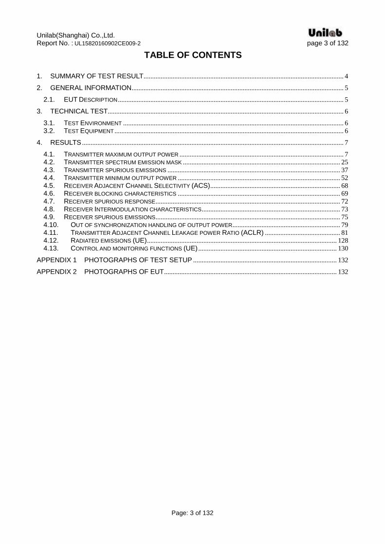
TABLE OF CONTENTS
1. SUMMARY OF TEST RESULT ..................................................................................................................... 4
2. GENERAL INFORMATION ............................................................................................................................ 5
2.1. EUT DESCRIPTION .................................................................................................................................... 5
3. TECHNICAL TEST.......................................................................................................................................... 6
3.1. TEST ENVIRONMENT ................................................................................................................................. 6 3.2. TEST EQUIPMENT ...................................................................................................................................... 6
4. RESULTS ......................................................................................................................................................... 7
4.1. TRANSMITTER MAXIMUM OUTPUT POWER ................................................................................................ 7 4.2. TRANSMITTER SPECTRUM EMISSION MASK ............................................................................................ 25 4.3. TRANSMITTER SPURIOUS EMISSIONS ..................................................................................................... 37 4.4. TRANSMITTER MINIMUM OUTPUT POWER ............................................................................................... 52 4.5. RECEIVER ADJACENT CHANNEL SELECTIVITY (ACS) ............................................................................ 68 4.6. RECEIVER BLOCKING CHARACTERISTICS ............................................................................................... 69 4.7. RECEIVER SPURIOUS RESPONSE ............................................................................................................ 72 4.8. RECEIVER INTERMODULATION CHARACTERISTICS ................................................................................. 73 4.9. RECEIVER SPURIOUS EMISSIONS ............................................................................................................ 75 4.10. OUT OF SYNCHRONIZATION HANDLING OF OUTPUT POWER ............................................................... 79 4.11. TRANSMITTER ADJACENT CHANNEL LEAKAGE POWER RATIO (ACLR) ............................................ 81 4.12. RADIATED EMISSIONS (UE) ............................................................................................................... 128 4.13. CONTROL AND MONITORING FUNCTIONS (UE) ................................................................................. 130
APPENDIX 1 PHOTOGRAPHS OF TEST SETUP .................................................................................... 132
APPENDIX 2 PHOTOGRAPHS OF EUT ..................................................................................................... 132
Unilab(Shanghai) Co.,Ltd. Report No. : UL15820160902CE009-2 page 4 of 132
Page: 4 of 132
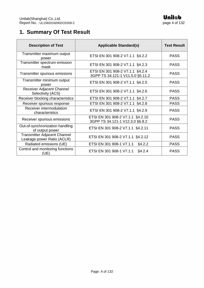
1. Summary Of Test Result
Description of Test Applicable Standard(s) Test Result
Transmitter maximum output power
ETSI EN 301 908-2 V7.1.1 §4.2.2 PASS
Transmitter spectrum emission mask
ETSI EN 301 908-2 V7.1.1 §4.2.3 PASS
Transmitter spurious emissions ETSI EN 301 908-2 V7.1.1 §4.2.4
3GPP TS 34.121-1 V11.5.0 §5.11.2 PASS
Transmitter minimum output power
ETSI EN 301 908-2 V7.1.1 §4.2.5 PASS
Receiver Adjacent Channel Selectivity (ACS)
ETSI EN 301 908-2 V7.1.1 §4.2.6 PASS
Receiver blocking characteristics ETSI EN 301 908-2 V7.1.1 §4.2.7 PASS
Receiver spurious response ETSI EN 301 908-2 V7.1.1 §4.2.8 PASS
Receiver intermodulation characteristics
ETSI EN 301 908-2 V7.1.1 §4.2.9 PASS
Receiver spurious emissions ETSI EN 301 908-2 V7.1.1 §4.2.10 3GPP TS 34.121-1 V12.3.0 §6.8.2
PASS
Out-of-synchronization handling of output power
ETSI EN 301 908-2 V7.1.1 §4.2.11 PASS
Transmitter Adjacent Channel Leakage power Ratio (ACLR)
ETSI EN 301 908-2 V7.1.1 §4.2.12 PASS
Radiated emissions (UE) ETSI EN 301 908-1 V7.1.1 §4.2.2 PASS
Control and monitoring functions (UE)
ETSI EN 301 908-1 V7.1.1 §4.2.4 PASS
Unilab(Shanghai) Co.,Ltd. Report No. : UL15820160902CE009-2 page 5 of 132
Page: 5 of 132
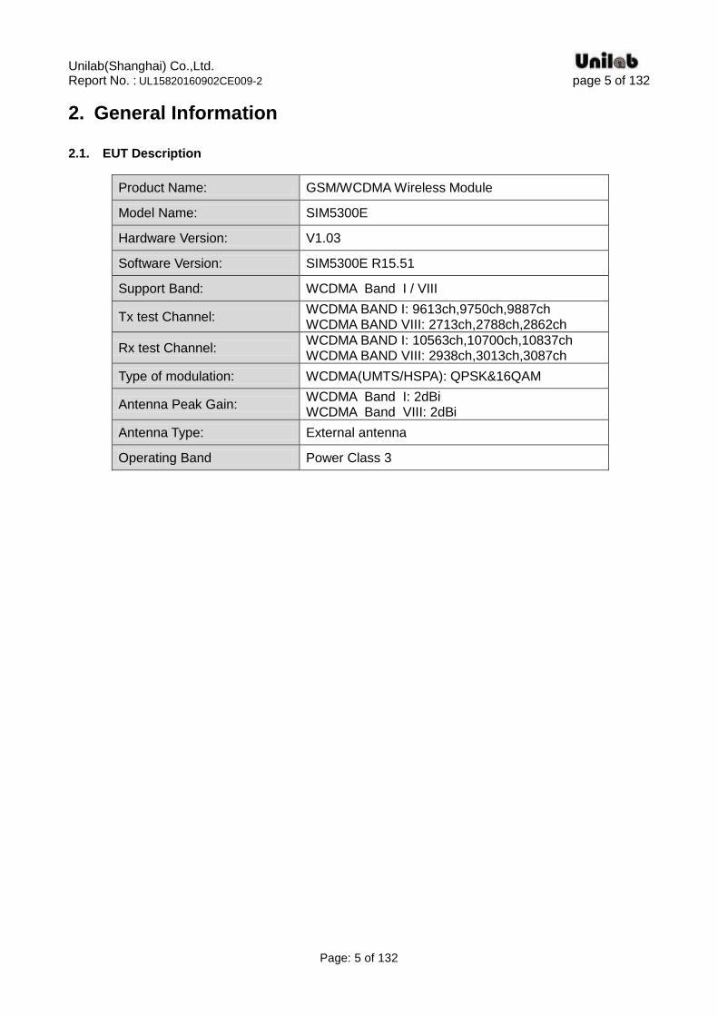
2. General Information 2.1. EUT Description
Product Name: GSM/WCDMA Wireless Module
Model Name: SIM5300E
Hardware Version: V1.03
Software Version: SIM5300E R15.51
Support Band: WCDMA Band I / VIII
Tx test Channel: WCDMA BAND I: 9613ch,9750ch,9887ch WCDMA BAND VIII: 2713ch,2788ch,2862ch
Rx test Channel: WCDMA BAND I: 10563ch,10700ch,10837ch WCDMA BAND VIII: 2938ch,3013ch,3087ch
Type of modulation: WCDMA(UMTS/HSPA): QPSK&16QAM
Antenna Peak Gain: WCDMA Band I: 2dBi WCDMA Band VIII: 2dBi
Antenna Type: External antenna
Operating Band Power Class 3

Unilab(Shanghai) Co.,Ltd. Report No. : UL15820160902CE009-2 page 6 of 132
Page: 6 of 132
3. Technical Test 3.1. Test Environment
Temperature (℃) 20
Humidity (%RH) 51
3.2. Test Equipment
Instrument Manufacturer Model Serial No. Cali. Due Date
Spectrum Analyzer Agilent N9038A MY51210142 11/05/2017
Radio Communication Tester R&S CMW500 106636 11/08/2016
Signal Generator Agilent N5183A MY50140938 09/23/2017
Power Splitter Agilent 11667C/ 52401
MY53806148 02/25/2017
ESG Vector Signal Generator Agilent E4438C MY42081708 09/22/2016
PSG Signal Generator Agilent E8257D MY45470010 09/22/2016
Preamplifier CEM EM30180 3008A0245 02/25/2017
Temperature Chamber WEISS DU/20/40 58226017340050 12/02/2017
Bilog Antenna Schwarzbeck VULB9160 9160-3316 09/19/2016
VHF-UHF-Biconical Antenna Schwarzbeck VUBA9117 9117-263 09/19/2016
Broad-Band Horn Antenna Schwarzbeck BBHA9120D 9120D-942 09/19/2016
Broad-Band Horn Antenna Schwarzbeck BBHA9120D 9120D-943 09/19/2016
Notes:
Normal: the Temperature is +20 ℃, the humidity is 44%, the voltage is 3.8V;
TL : the Temperature is -10 ℃;
TH : the Temperature is +55℃;
VL : the voltage is 3.4V DC VH : the voltage is 4.4V DC
There is only show typical and worst test plots in this report.

Unilab(Shanghai) Co.,Ltd. Report No. : UL15820160902CE009-2 page 7 of 132
Page: 7 of 132
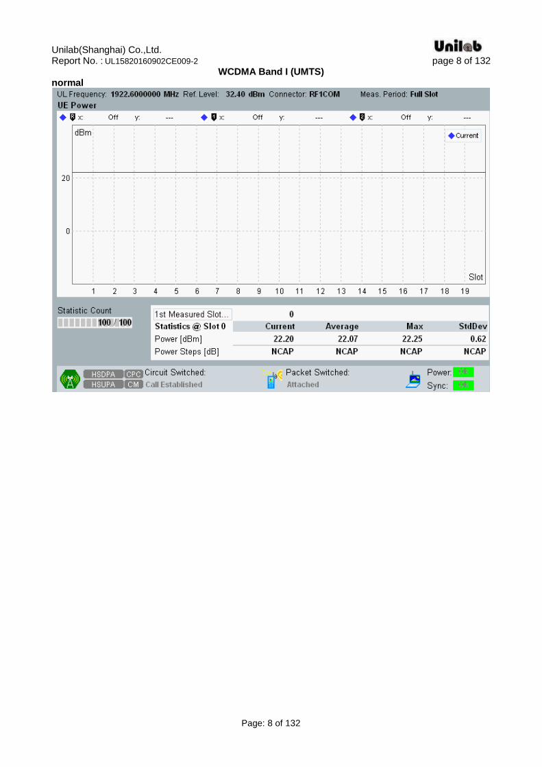
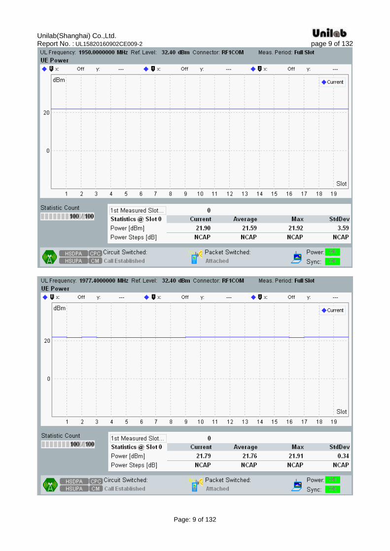
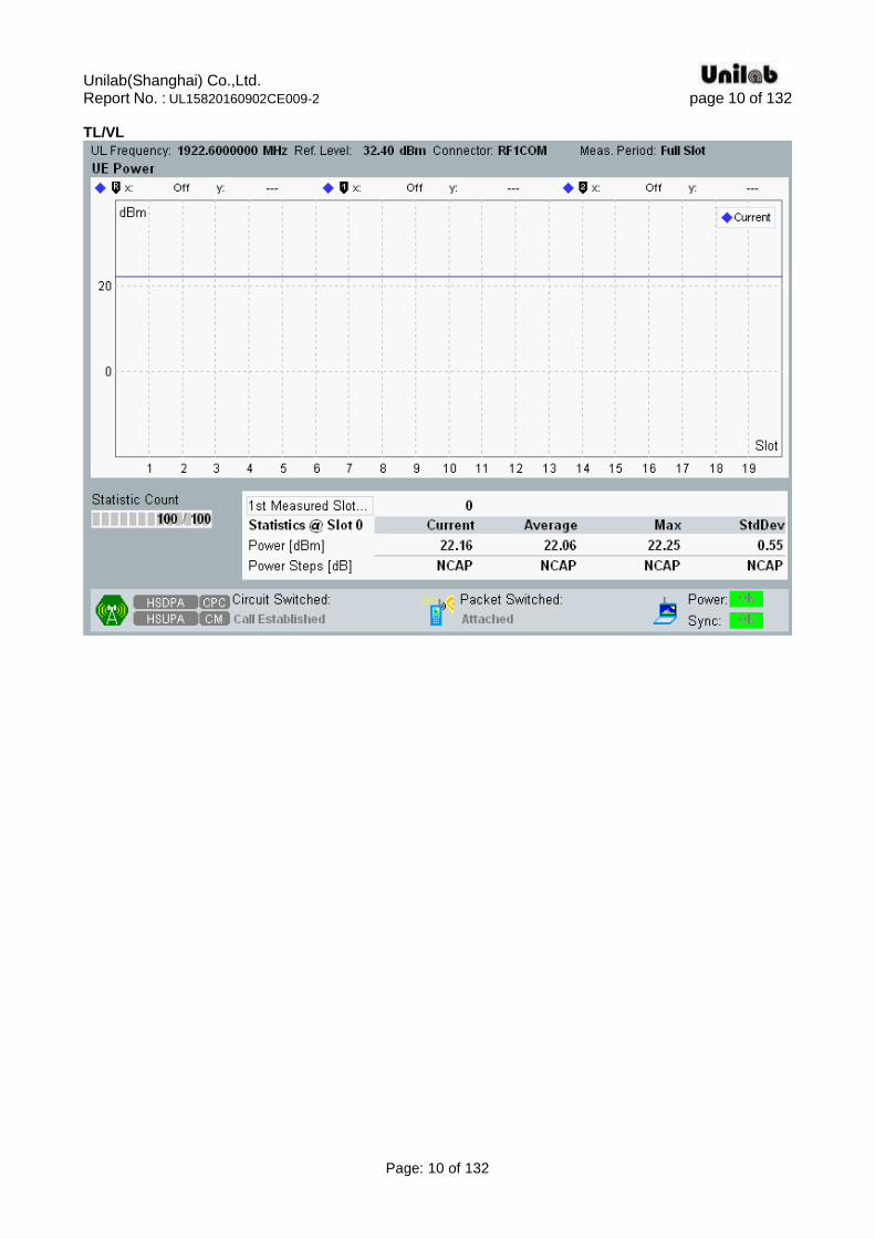
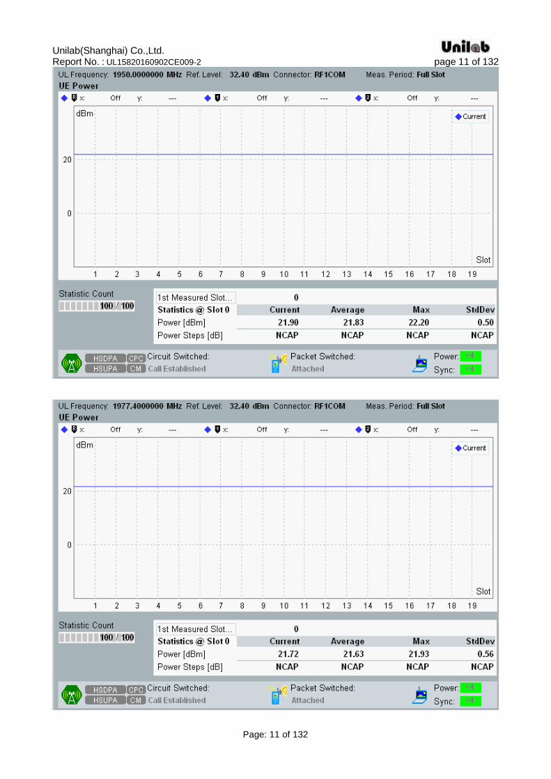
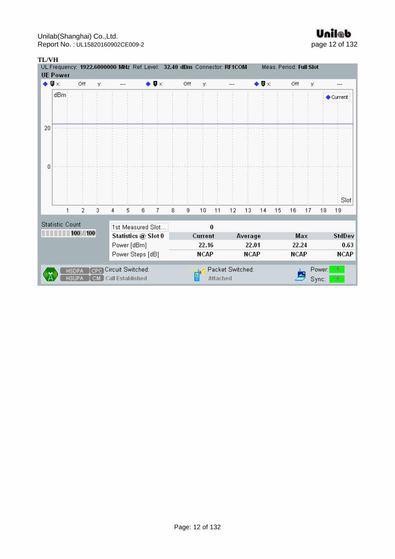
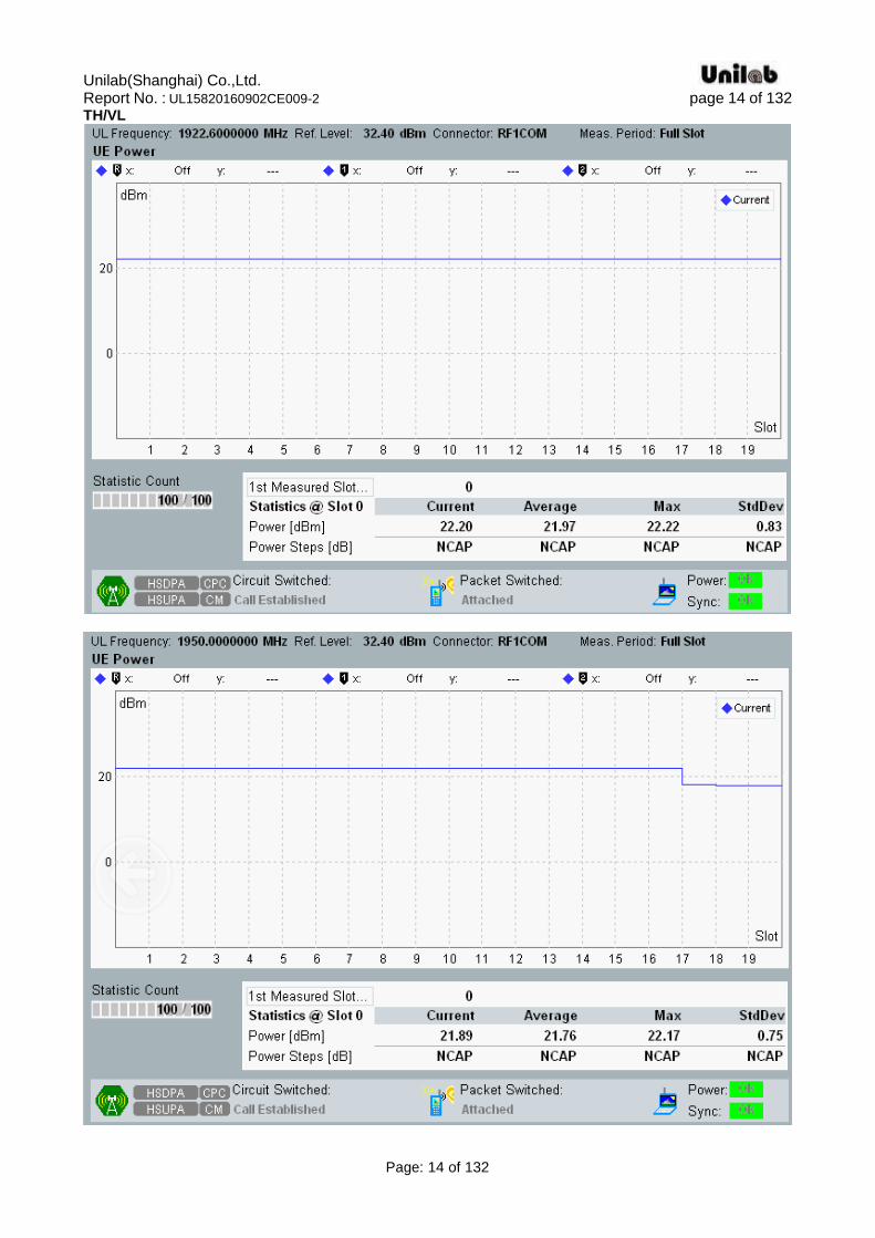
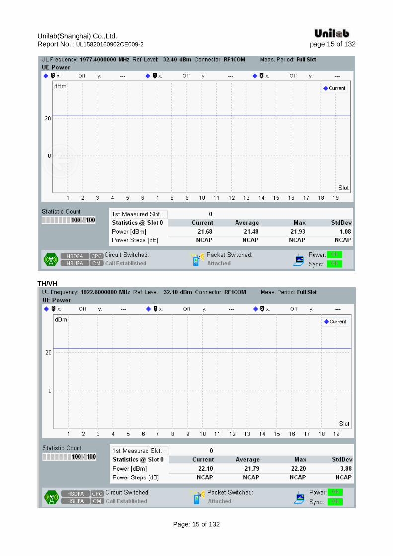
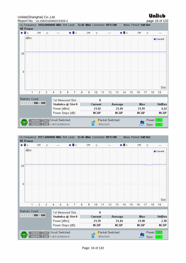
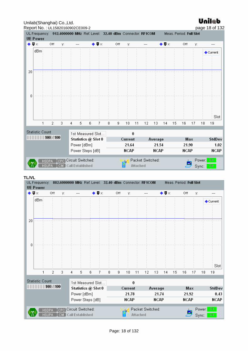
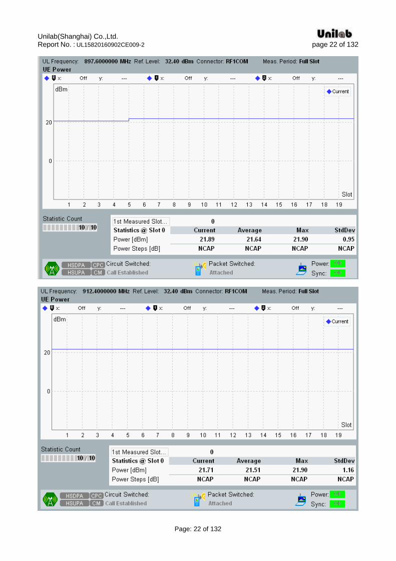
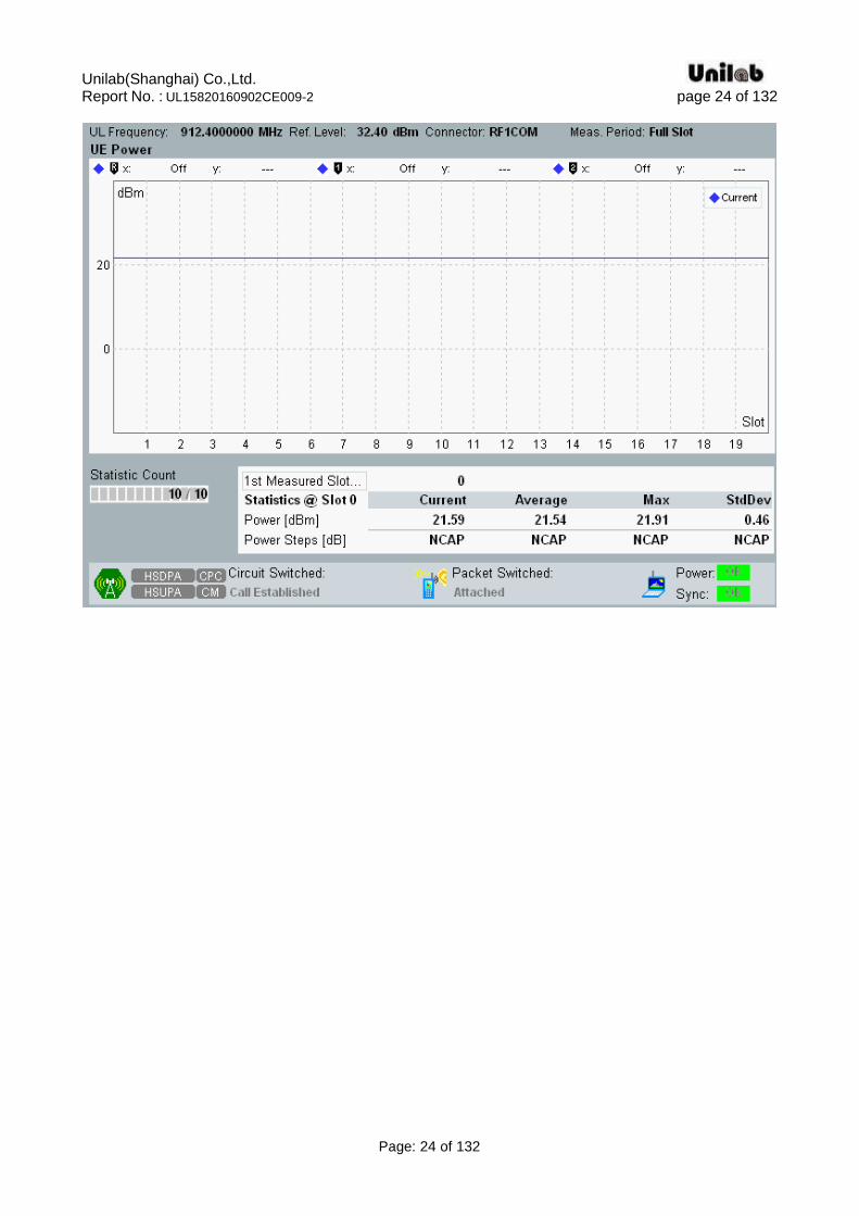
4. Results 4.1. Transmitter maximum output power Standard Applicable According to ETSI EN 301 908-2 V7.1.1(2013-10) §4.2.2, The nominal power defined is the broadband
transmit power of the UE, i.e. the power in a bandwidth of at least (1 + α ) times the chip rate of the radio
access mode. The period of measurement shall be at least one timeslot. Limits The UE maximum output power shall be within the shown value in table 4.2.2.1.2-1 even for the multi-code DPDCH transmission mode.
Table 4.2.2.1.2-1: UE power classes
Note 1: These requirements do not take into account the maximum power reduction allowed to the UE in the presence of HS-DPCCH and E-DCH specified in TS 125 101 [5]. Note 2: The range of UE maximum output power for the various power classes are specified in TS 125 101 [5],clause 6.2.1. The values in table 4.2.2.1.2-1 correspond to the measurement limits taking into account the measurement uncertainty of measurement equipment (see clause 5.2) Test procedure 1) Set and send continuously Up power control commands to the UE.
2) Measure the mean power of the UE in a bandwidth of at least (1+α ) times the chip rate of the radio
access mode. The mean power shall be averaged over at least one timeslot. Test Result
Band Test
Environment
Transmitter maximum output power (dBm)
Low Channel
Middle Channel
High Channel
Result
WCDMA Band I
normal 22.20 21.90 21.79 Pass
TL/VL 22.16 21.90 21.72 Pass
TL/VH 22.16 21.87 21.66 Pass
TH/VL 22.20 21.89 21.68 Pass
TH/VH 22.10 21.92 21.70 Pass
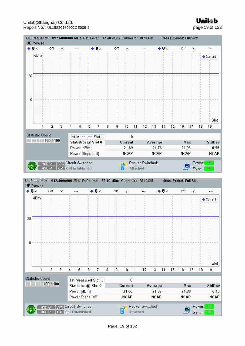
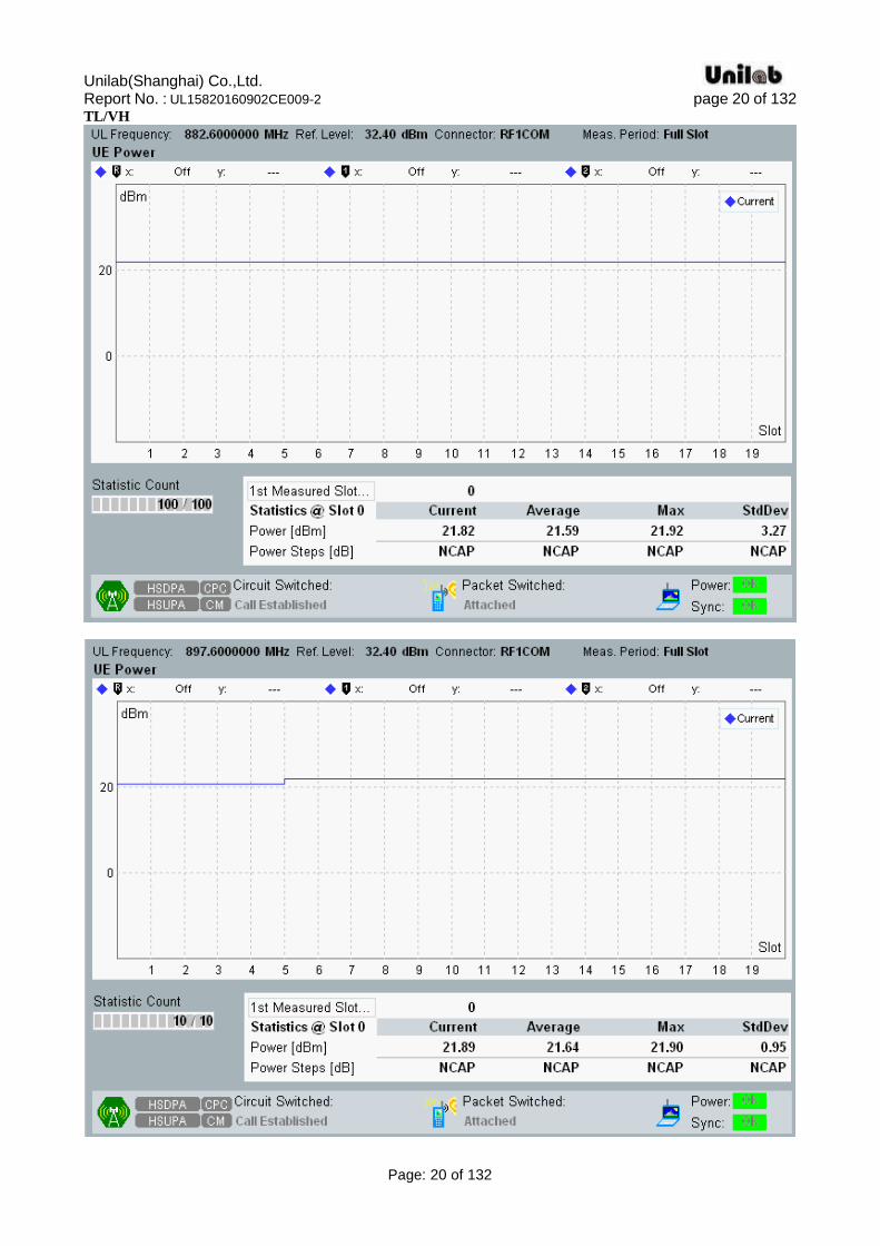
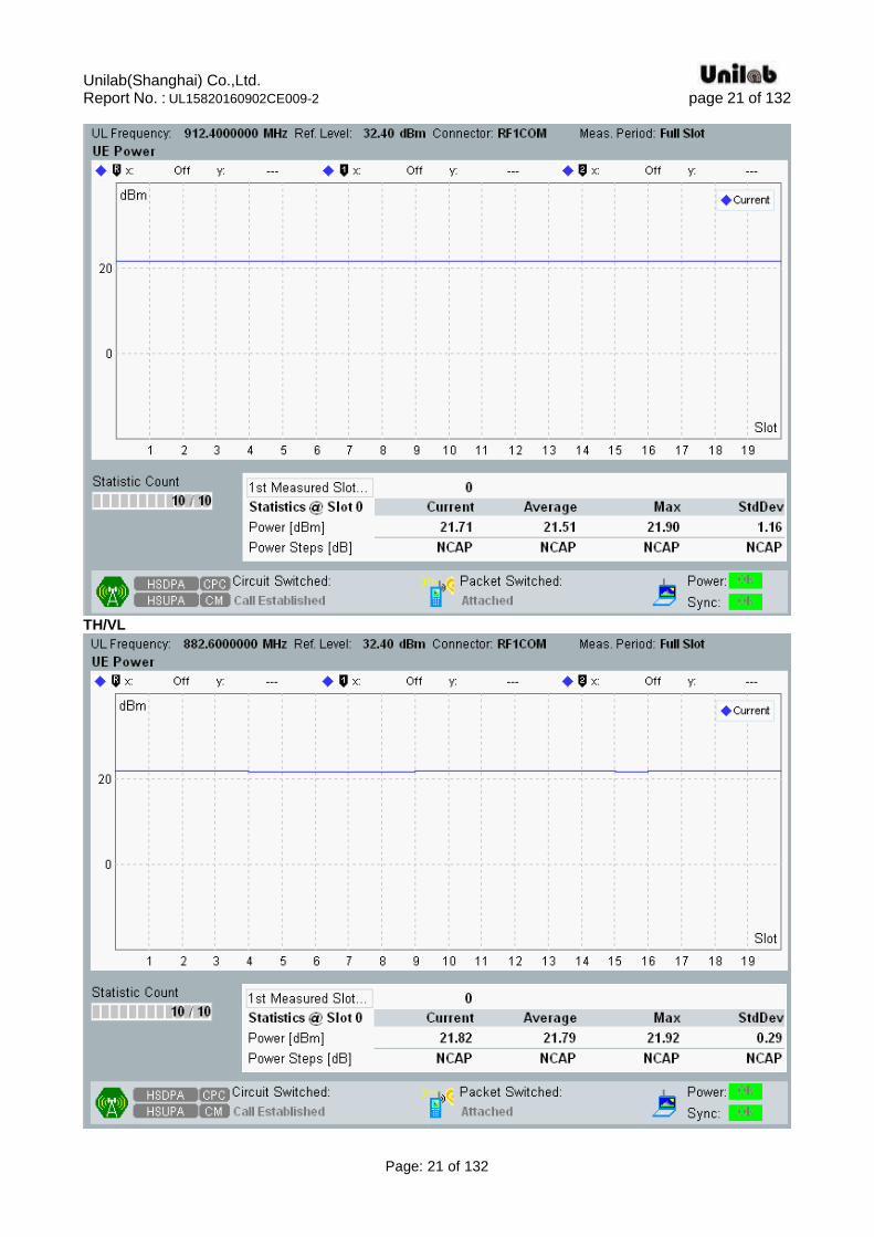
WCDMA Band VIII
normal 21.76 21.91 21.64 Pass
TL/VL 21.78 21.89 21.66 Pass
TL/VH 21.82 21.89 21.71 Pass
TH/VL 21.82 21.89 21.71 Pass
TH/VH 21.82 21.87 21.59 Pass
Please refer to the following data plots.
Unilab(Shanghai) Co.,Ltd. Report No. : UL15820160902CE009-2 page 8 of 132
Page: 8 of 132
WCDMA Band I (UMTS) normal
Unilab(Shanghai) Co.,Ltd. Report No. : UL15820160902CE009-2 page 9 of 132
Page: 9 of 132
Unilab(Shanghai) Co.,Ltd. Report No. : UL15820160902CE009-2 page 10 of 132
Page: 10 of 132
TL/VL
Unilab(Shanghai) Co.,Ltd. Report No. : UL15820160902CE009-2 page 11 of 132
Page: 11 of 132
Unilab(Shanghai) Co.,Ltd. Report No. : UL15820160902CE009-2 page 12 of 132
Page: 12 of 132
TL/VH

Unilab(Shanghai) Co.,Ltd. Report No. : UL15820160902CE009-2 page 13 of 132
Page: 13 of 132
Unilab(Shanghai) Co.,Ltd. Report No. : UL15820160902CE009-2 page 14 of 132
Page: 14 of 132
TH/VL
Unilab(Shanghai) Co.,Ltd. Report No. : UL15820160902CE009-2 page 15 of 132
Page: 15 of 132
TH/VH
Unilab(Shanghai) Co.,Ltd. Report No. : UL15820160902CE009-2 page 16 of 132
Page: 16 of 132

Unilab(Shanghai) Co.,Ltd. Report No. : UL15820160902CE009-2 page 17 of 132
Page: 17 of 132
WCDMA Band VIII (UMTS) normal
Unilab(Shanghai) Co.,Ltd. Report No. : UL15820160902CE009-2 page 18 of 132
Page: 18 of 132
TL/VL
Unilab(Shanghai) Co.,Ltd. Report No. : UL15820160902CE009-2 page 19 of 132
Page: 19 of 132
Unilab(Shanghai) Co.,Ltd. Report No. : UL15820160902CE009-2 page 20 of 132
Page: 20 of 132
TL/VH
Unilab(Shanghai) Co.,Ltd. Report No. : UL15820160902CE009-2 page 21 of 132
Page: 21 of 132
TH/VL
Unilab(Shanghai) Co.,Ltd. Report No. : UL15820160902CE009-2 page 22 of 132
Page: 22 of 132

Unilab(Shanghai) Co.,Ltd. Report No. : UL15820160902CE009-2 page 23 of 132
Page: 23 of 132
TH/VH
Unilab(Shanghai) Co.,Ltd. Report No. : UL15820160902CE009-2 page 24 of 132
Page: 24 of 132
Unilab(Shanghai) Co.,Ltd. Report No. : UL15820160902CE009-2 page 25 of 132
Page: 25 of 132
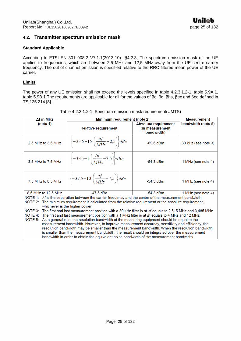
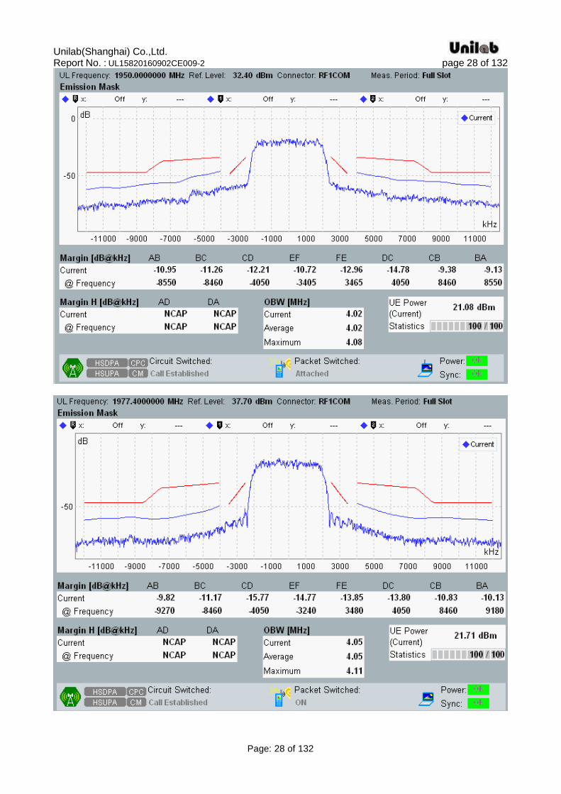
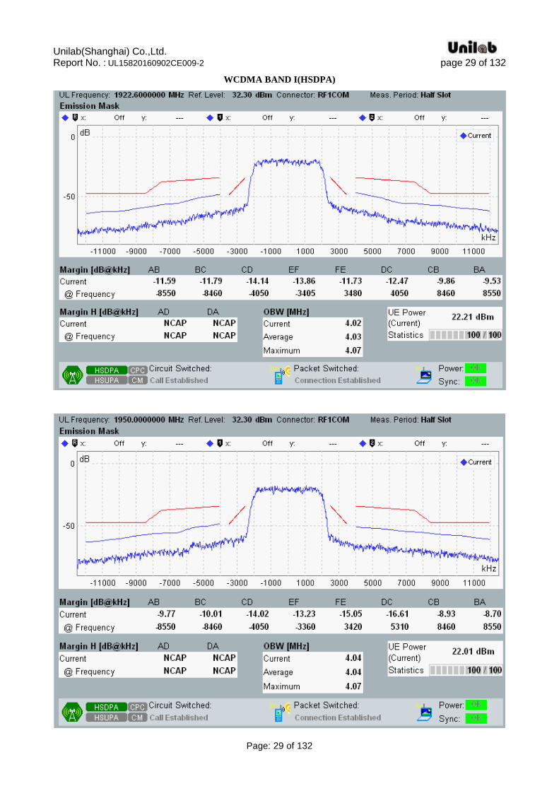
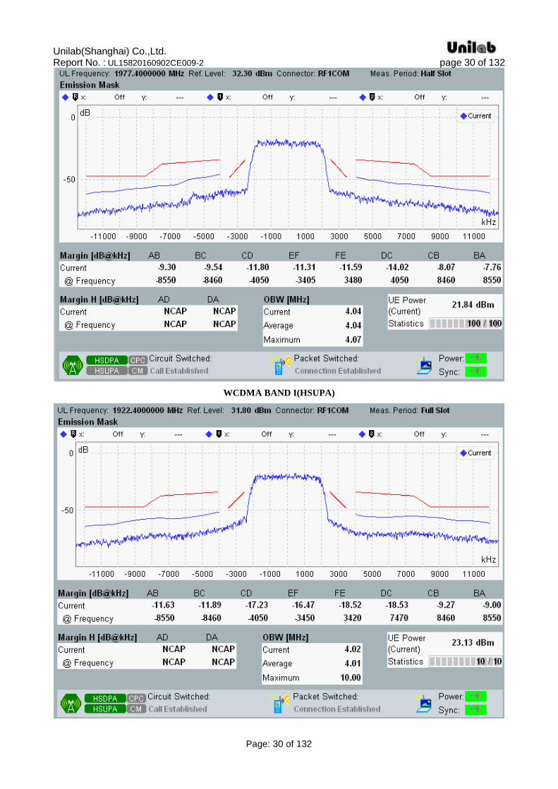
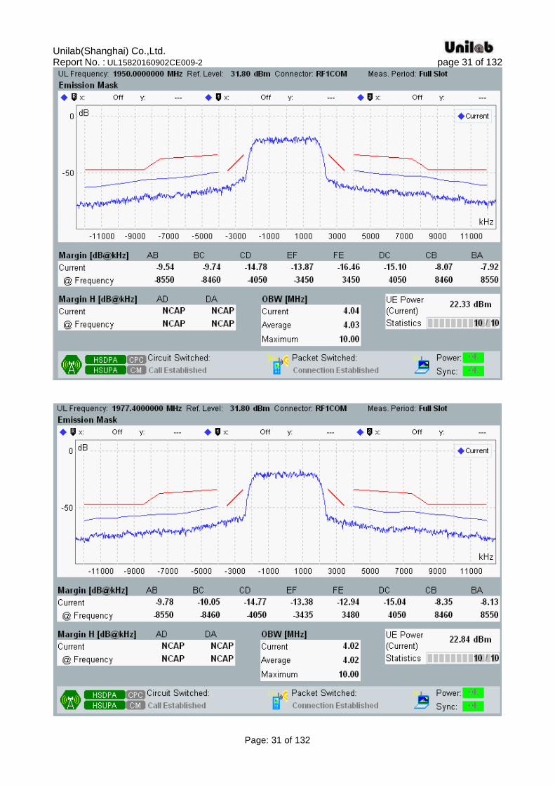
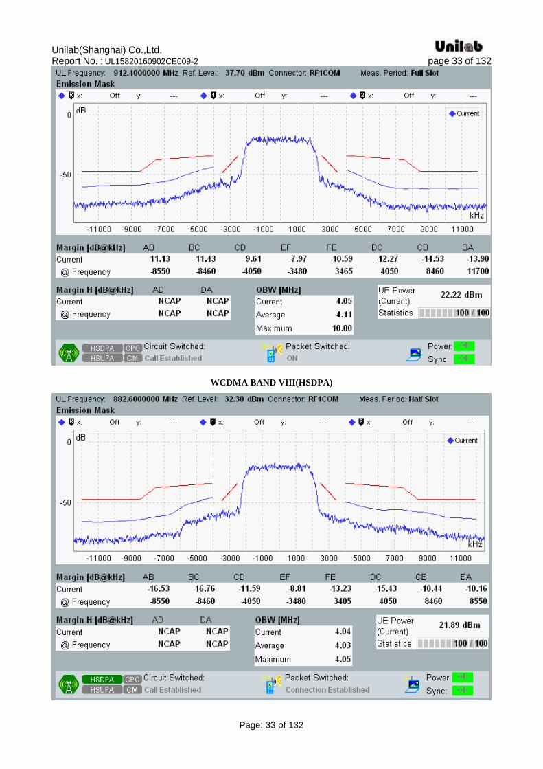
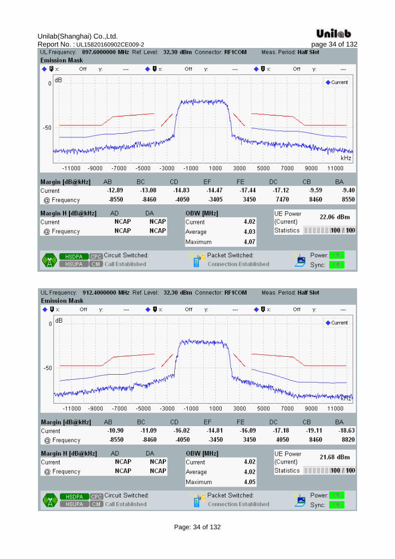
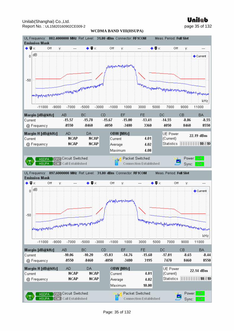
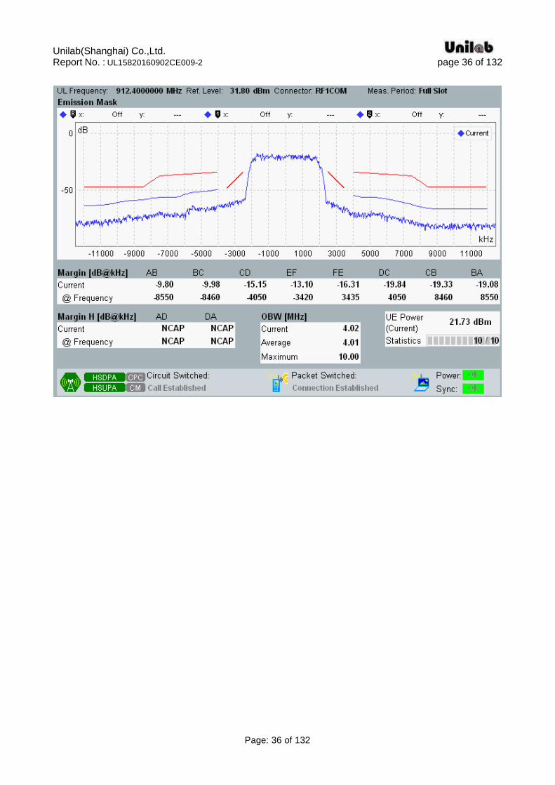
4.2. Transmitter spectrum emission mask Standard Applicable According to ETSI EN 301 908-2 V7.1.1(2013-10) §4.2.3, The spectrum emission mask of the UE applies to frequencies, which are between 2,5 MHz and 12,5 MHz away from the UE centre carrier frequency. The out of channel emission is specified relative to the RRC filtered mean power of the UE carrier. Limits The power of any UE emission shall not exceed the levels specified in table 4.2.3.1.2-1, table 5.9A.1, table 5.9B.1.The requirements are applicable for all for the values of βc, βd, βhs, βec and βed defined in TS 125 214 [8].
Table 4.2.3.1.2-1: Spectrum emission mask requirement(UMTS)

Unilab(Shanghai) Co.,Ltd. Report No. : UL15820160902CE009-2 page 26 of 132
Page: 26 of 132
Table 5.9A.1: Spectrum emission mask requirement(HSDPA)
Table 5.9B.1: Spectrum emission mask requirement(E-DCH)
Unilab(Shanghai) Co.,Ltd. Report No. : UL15820160902CE009-2 page 27 of 132
Page: 27 of 132
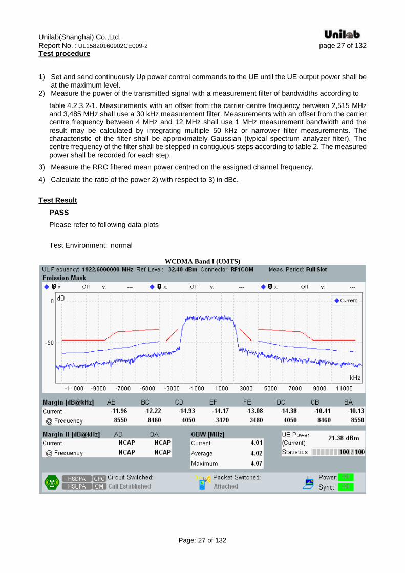
Test procedure
1) Set and send continuously Up power control commands to the UE until the UE output power shall be
at the maximum level. 2) Measure the power of the transmitted signal with a measurement filter of bandwidths according to
table 4.2.3.2-1. Measurements with an offset from the carrier centre frequency between 2,515 MHz and 3,485 MHz shall use a 30 kHz measurement filter. Measurements with an offset from the carrier centre frequency between 4 MHz and 12 MHz shall use 1 MHz measurement bandwidth and the result may be calculated by integrating multiple 50 kHz or narrower filter measurements. The characteristic of the filter shall be approximately Gaussian (typical spectrum analyzer filter). The centre frequency of the filter shall be stepped in contiguous steps according to table 2. The measured power shall be recorded for each step.
3) Measure the RRC filtered mean power centred on the assigned channel frequency.
4) Calculate the ratio of the power 2) with respect to 3) in dBc.
Test Result
PASS
Please refer to following data plots
Test Environment: normal
WCDMA Band I (UMTS)
Unilab(Shanghai) Co.,Ltd. Report No. : UL15820160902CE009-2 page 28 of 132
Page: 28 of 132
Unilab(Shanghai) Co.,Ltd. Report No. : UL15820160902CE009-2 page 29 of 132
Page: 29 of 132
WCDMA BAND I(HSDPA)
Unilab(Shanghai) Co.,Ltd. Report No. : UL15820160902CE009-2 page 30 of 132
Page: 30 of 132
WCDMA BAND I(HSUPA)
Unilab(Shanghai) Co.,Ltd. Report No. : UL15820160902CE009-2 page 31 of 132
Page: 31 of 132

Unilab(Shanghai) Co.,Ltd. Report No. : UL15820160902CE009-2 page 32 of 132
Page: 32 of 132
WCDMA Band VIII (UMTS)
Unilab(Shanghai) Co.,Ltd. Report No. : UL15820160902CE009-2 page 33 of 132
Page: 33 of 132
WCDMA BAND VIII(HSDPA)
Unilab(Shanghai) Co.,Ltd. Report No. : UL15820160902CE009-2 page 34 of 132
Page: 34 of 132
Unilab(Shanghai) Co.,Ltd. Report No. : UL15820160902CE009-2 page 35 of 132
Page: 35 of 132
WCDMA BAND VIII(HSUPA)
Unilab(Shanghai) Co.,Ltd. Report No. : UL15820160902CE009-2 page 36 of 132
Page: 36 of 132
Unilab(Shanghai) Co.,Ltd. Report No. : UL15820160902CE009-2 page 37 of 132
Page: 37 of 132
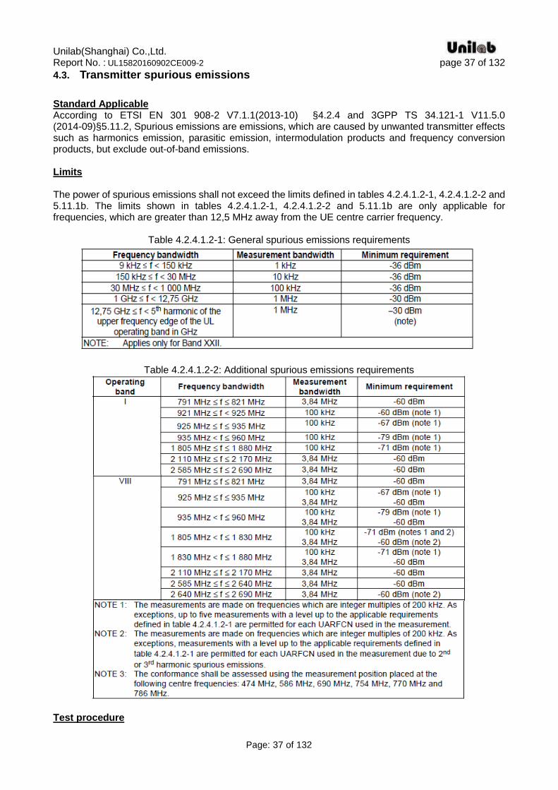
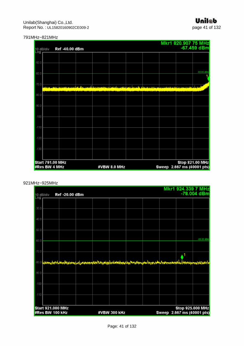
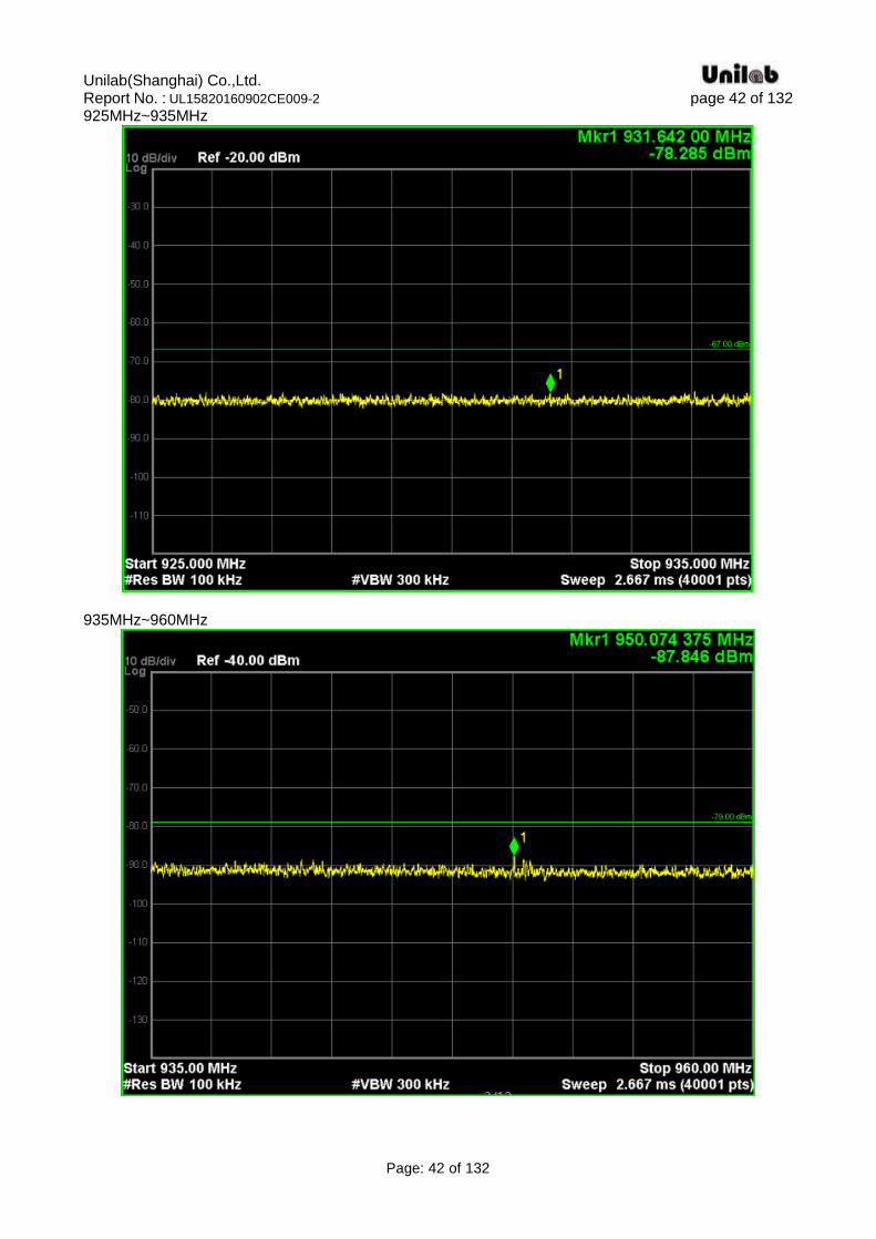
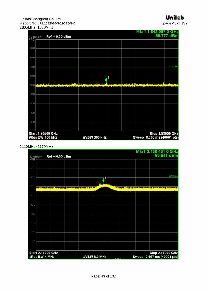
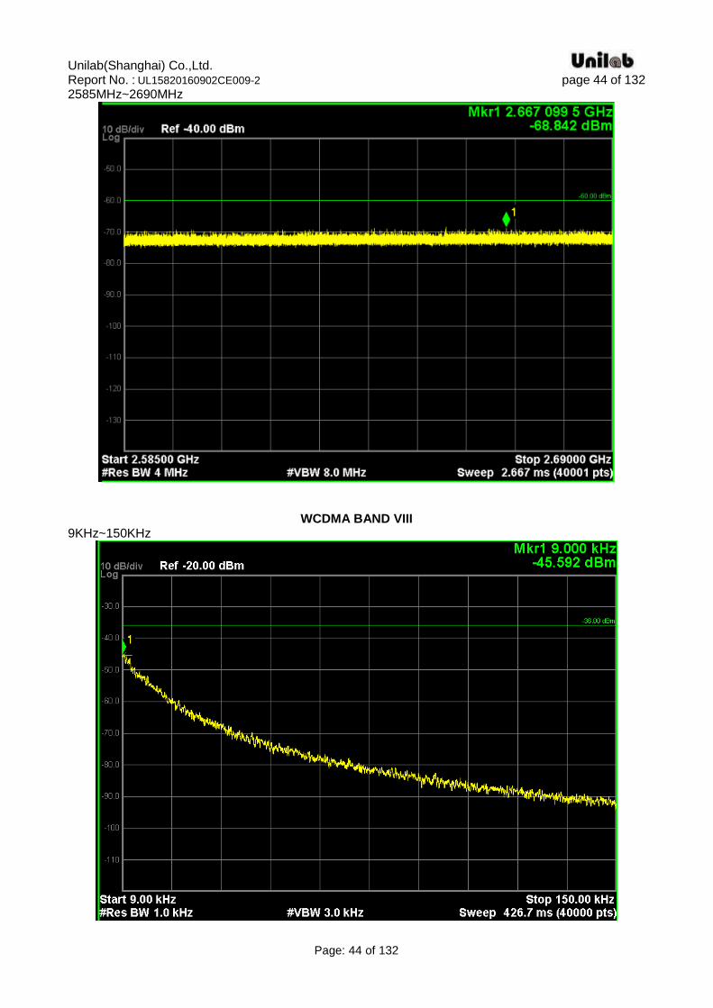
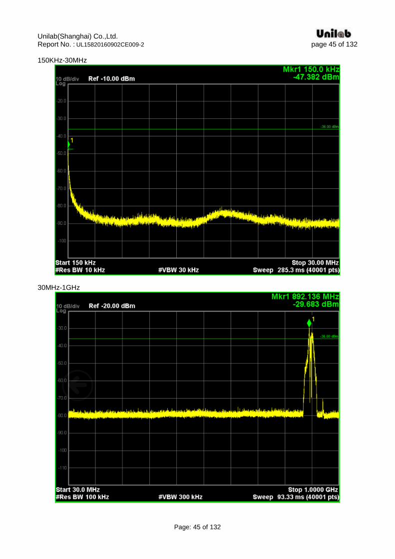
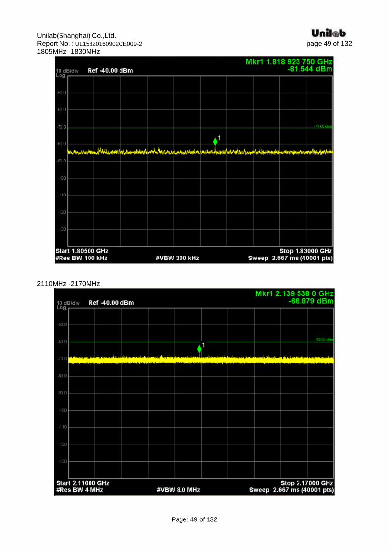
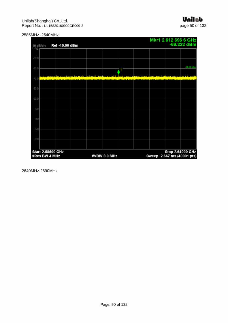
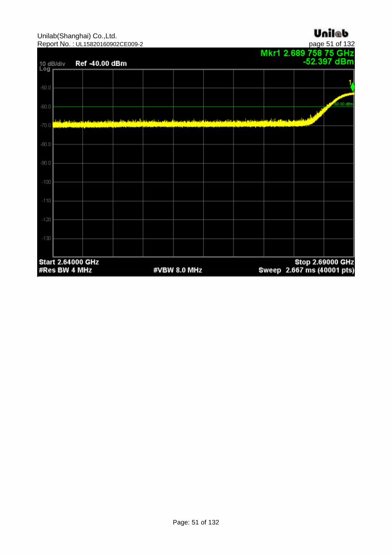
4.3. Transmitter spurious emissions
Standard Applicable According to ETSI EN 301 908-2 V7.1.1(2013-10) §4.2.4 and 3GPP TS 34.121-1 V11.5.0 (2014-09)§5.11.2, Spurious emissions are emissions, which are caused by unwanted transmitter effects such as harmonics emission, parasitic emission, intermodulation products and frequency conversion products, but exclude out-of-band emissions. Limits The power of spurious emissions shall not exceed the limits defined in tables 4.2.4.1.2-1, 4.2.4.1.2-2 and 5.11.1b. The limits shown in tables 4.2.4.1.2-1, 4.2.4.1.2-2 and 5.11.1b are only applicable for frequencies, which are greater than 12,5 MHz away from the UE centre carrier frequency.
Table 4.2.4.1.2-1: General spurious emissions requirements
Table 4.2.4.1.2-2: Additional spurious emissions requirements
Test procedure
Unilab(Shanghai) Co.,Ltd. Report No. : UL15820160902CE009-2 page 38 of 132
Page: 38 of 132
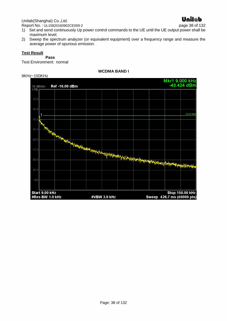
1) Set and send continuously Up power control commands to the UE until the UE output power shall be maximum level.
2) Sweep the spectrum analyzer (or equivalent equipment) over a frequency range and measure the average power of spurious emission.
Test Result Pass Test Environment: normal
WCDMA BAND I 9KHz~150KHz
Unilab(Shanghai) Co.,Ltd. Report No. : UL15820160902CE009-2 page 39 of 132
Page: 39 of 132
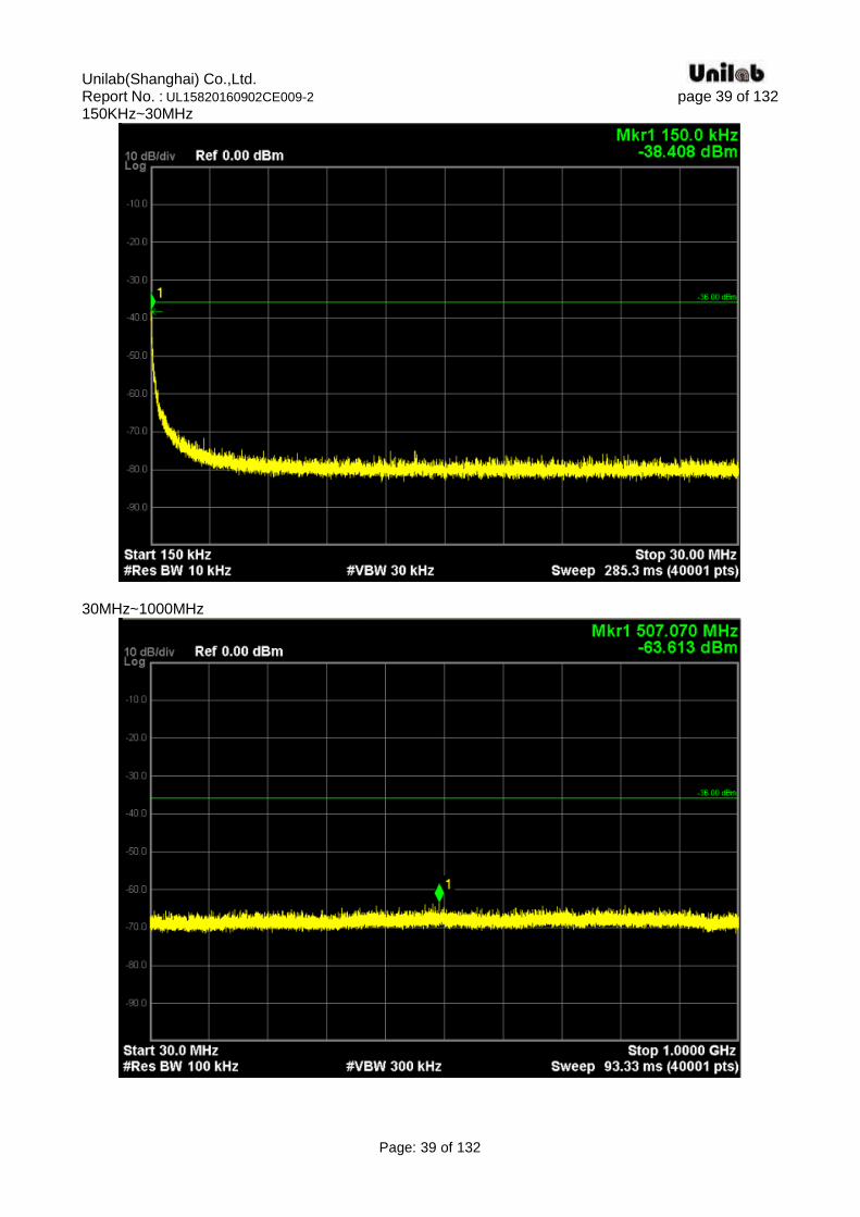
150KHz~30MHz
30MHz~1000MHz
Unilab(Shanghai) Co.,Ltd. Report No. : UL15820160902CE009-2 page 40 of 132
Page: 40 of 132
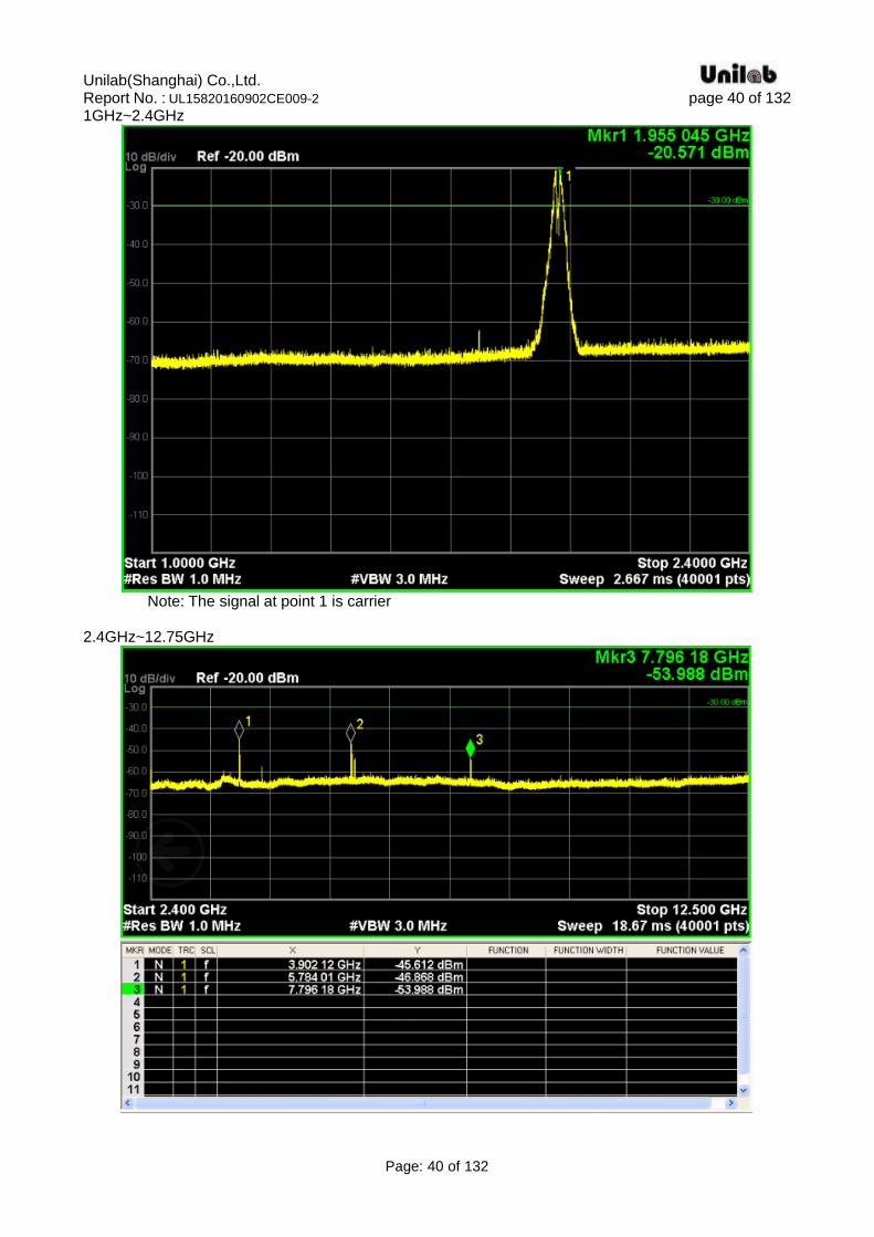
1GHz~2.4GHz
Note: The signal at point 1 is carrier 2.4GHz~12.75GHz
Unilab(Shanghai) Co.,Ltd. Report No. : UL15820160902CE009-2 page 41 of 132
Page: 41 of 132
791MHz~821MHz
921MHz~925MHz
Unilab(Shanghai) Co.,Ltd. Report No. : UL15820160902CE009-2 page 42 of 132
Page: 42 of 132
925MHz~935MHz
935MHz~960MHz
Unilab(Shanghai) Co.,Ltd. Report No. : UL15820160902CE009-2 page 43 of 132
Page: 43 of 132
1805MHz~1880MHz
2110MHz~2170MHz
Unilab(Shanghai) Co.,Ltd. Report No. : UL15820160902CE009-2 page 44 of 132
Page: 44 of 132
2585MHz~2690MHz
WCDMA BAND VIII 9KHz~150KHz
Unilab(Shanghai) Co.,Ltd. Report No. : UL15820160902CE009-2 page 45 of 132
Page: 45 of 132
150KHz-30MHz
30MHz-1GHz
Unilab(Shanghai) Co.,Ltd. Report No. : UL15820160902CE009-2 page 46 of 132
Page: 46 of 132
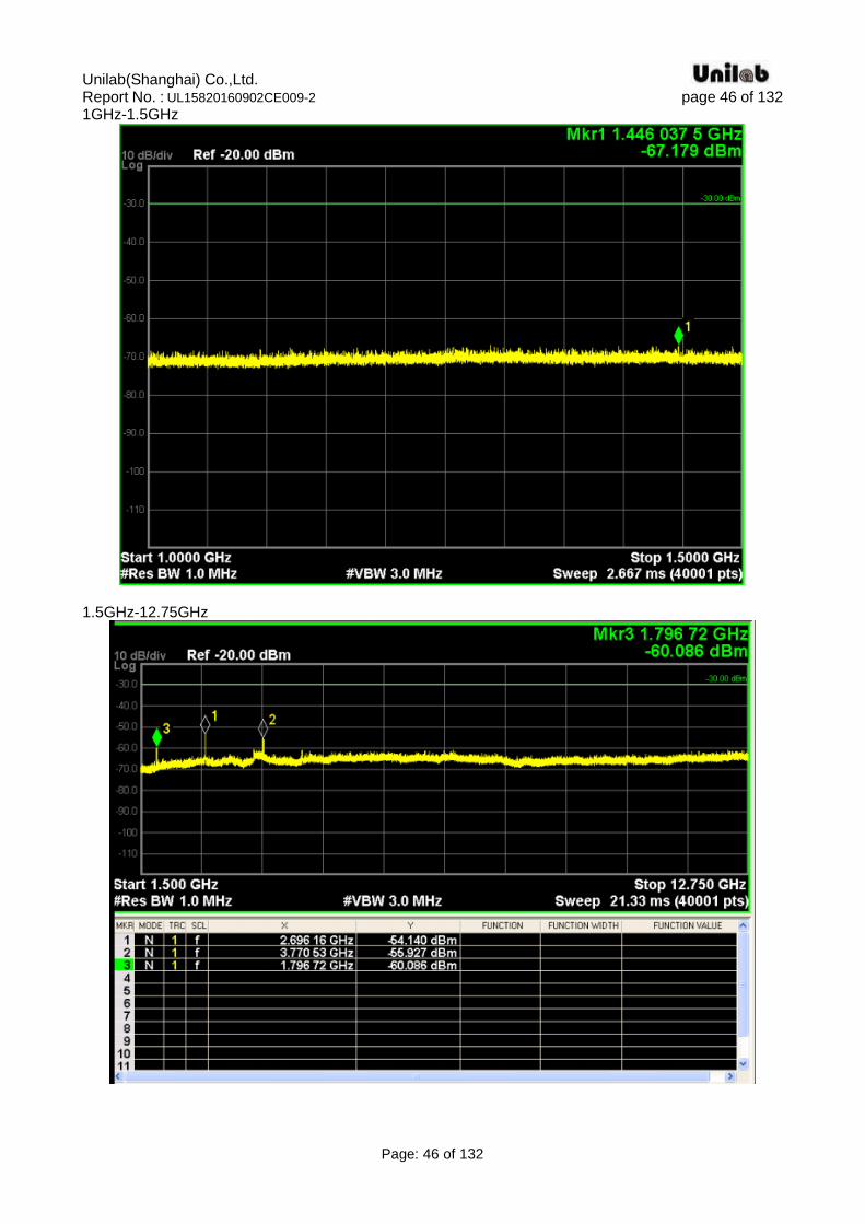
1GHz-1.5GHz
1.5GHz-12.75GHz
Unilab(Shanghai) Co.,Ltd. Report No. : UL15820160902CE009-2 page 47 of 132
Page: 47 of 132
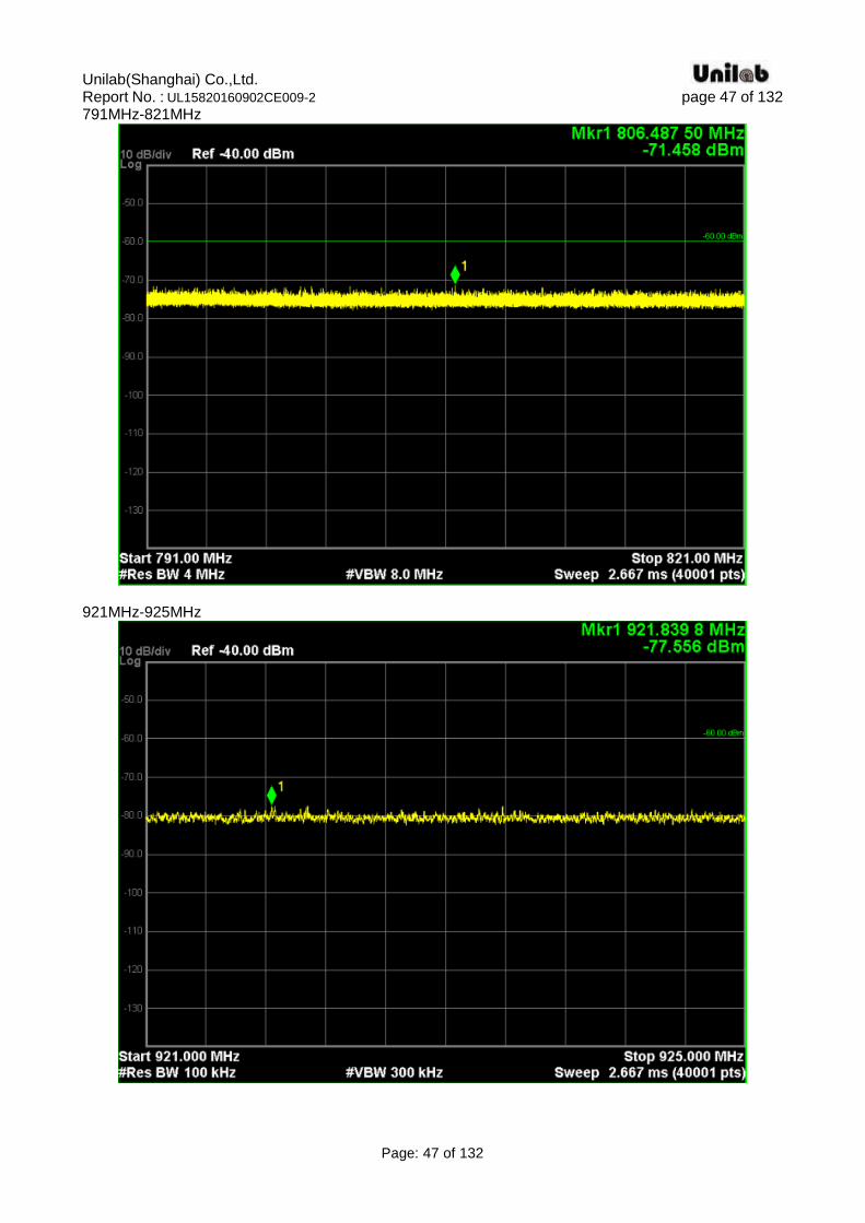
791MHz-821MHz
921MHz-925MHz
Unilab(Shanghai) Co.,Ltd. Report No. : UL15820160902CE009-2 page 48 of 132
Page: 48 of 132
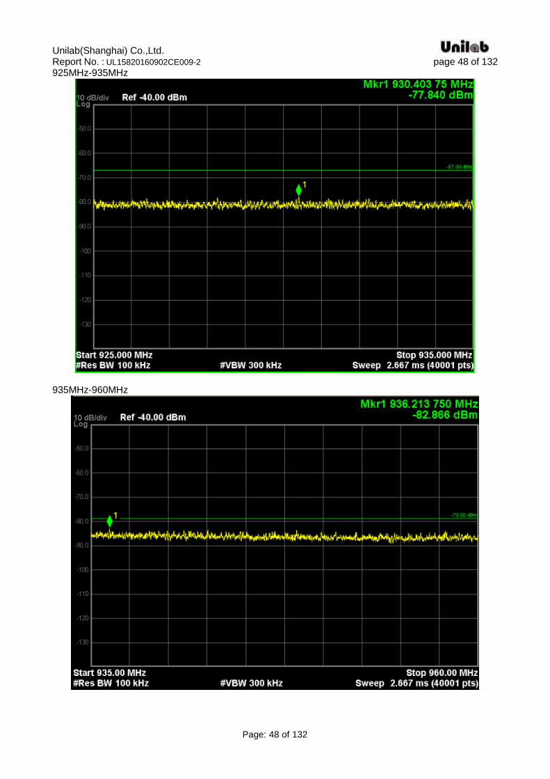
925MHz-935MHz
935MHz-960MHz
Unilab(Shanghai) Co.,Ltd. Report No. : UL15820160902CE009-2 page 49 of 132
Page: 49 of 132
1805MHz -1830MHz
2110MHz -2170MHz
Unilab(Shanghai) Co.,Ltd. Report No. : UL15820160902CE009-2 page 50 of 132
Page: 50 of 132
2585MHz -2640MHz
2640MHz-2690MHz
Unilab(Shanghai) Co.,Ltd. Report No. : UL15820160902CE009-2 page 51 of 132
Page: 51 of 132
Unilab(Shanghai) Co.,Ltd. Report No. : UL15820160902CE009-2 page 52 of 132
Page: 52 of 132
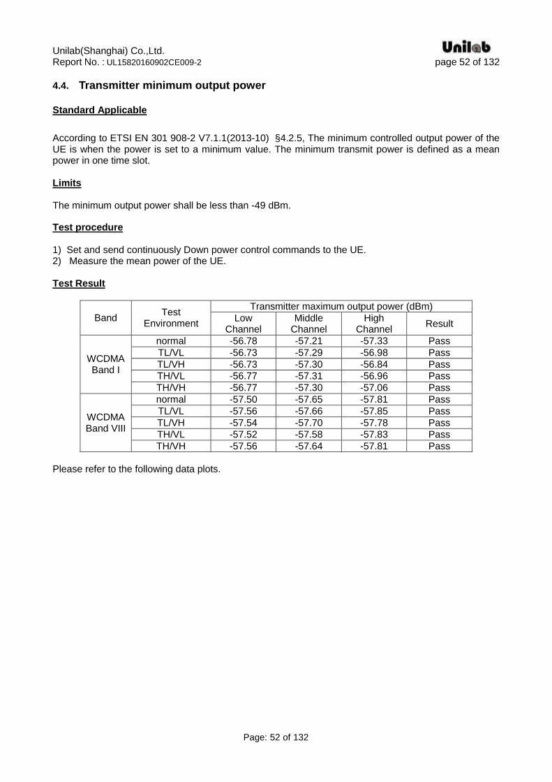
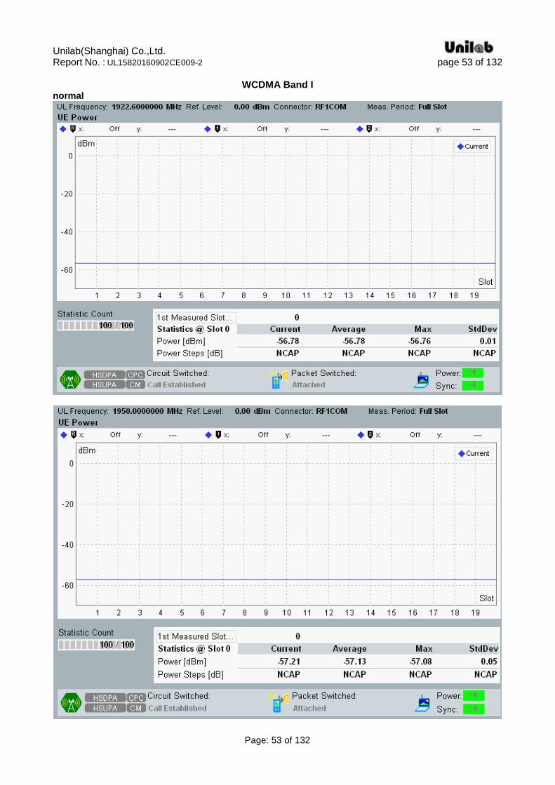
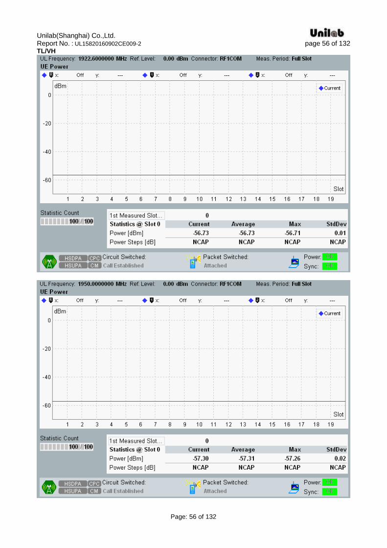
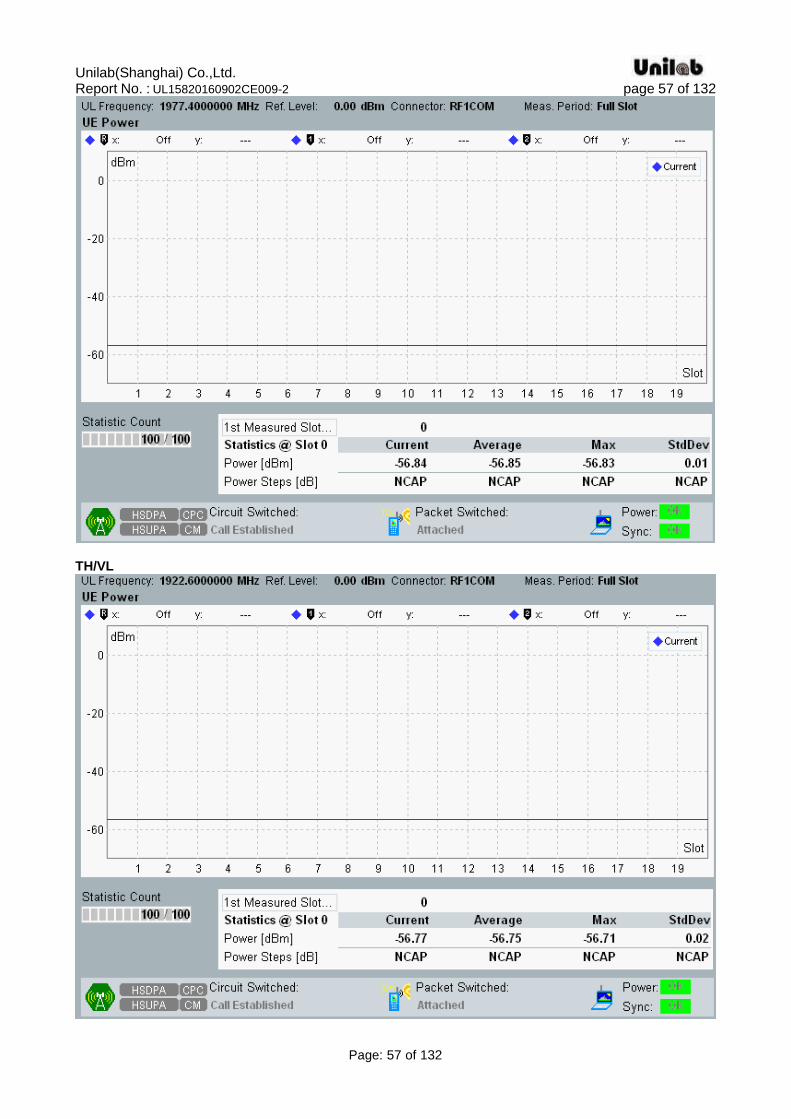
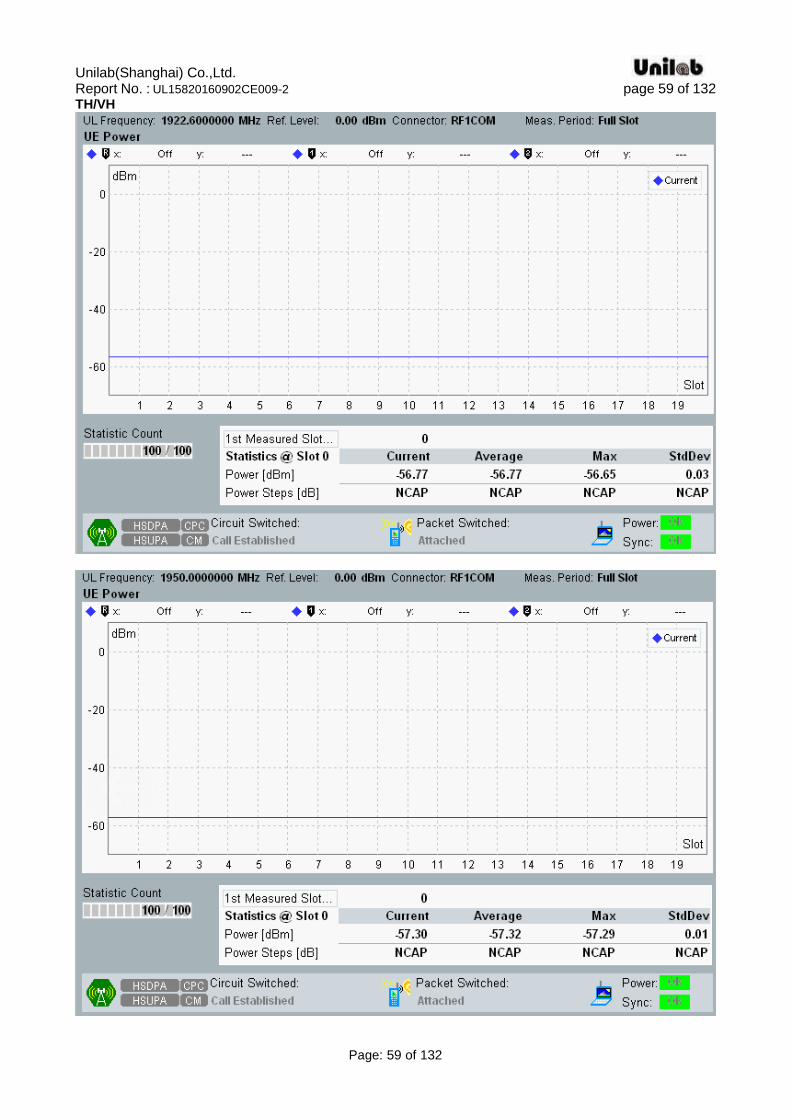
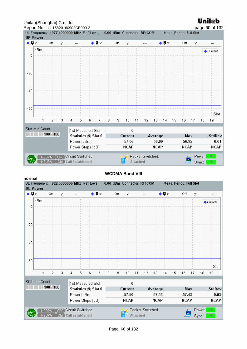
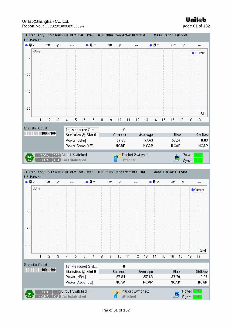
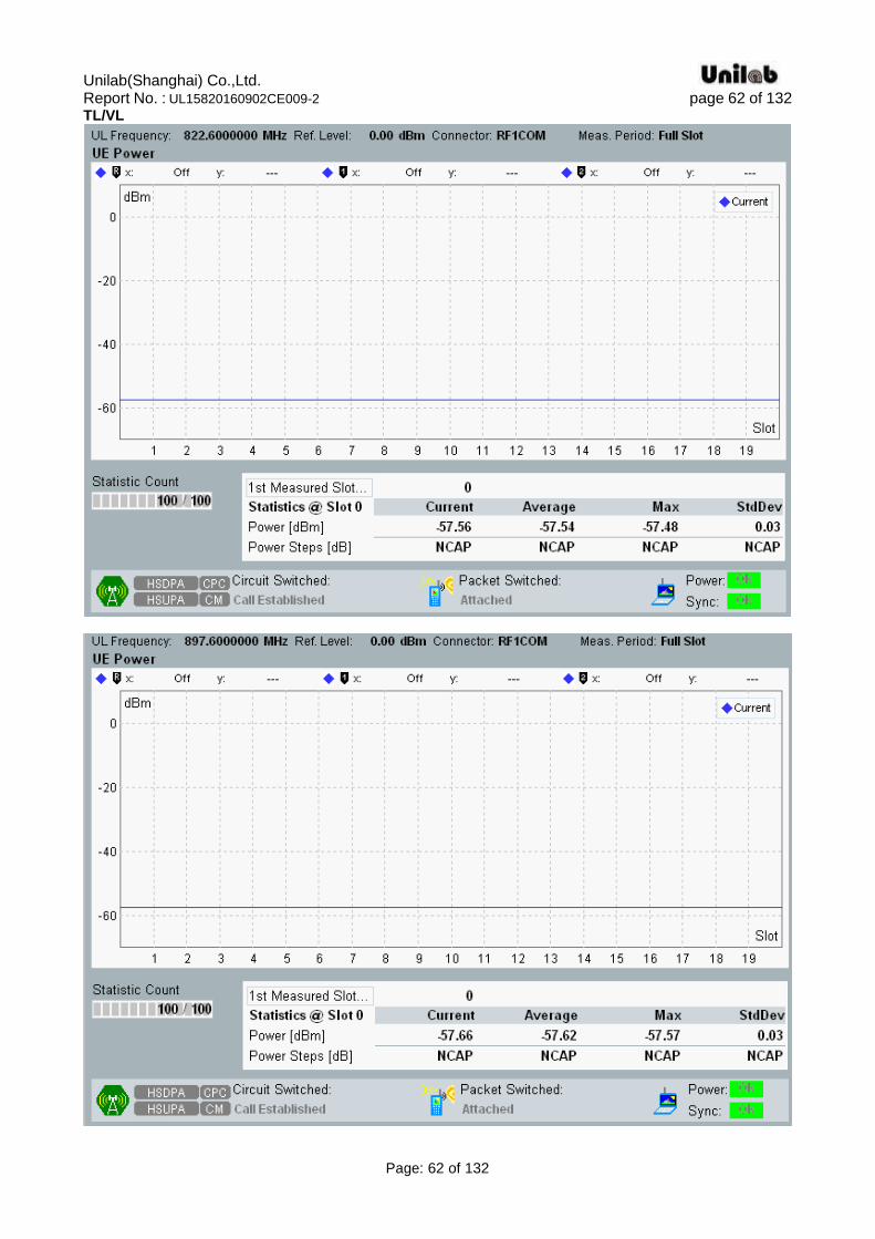
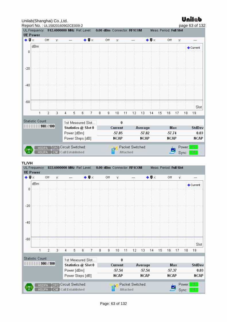
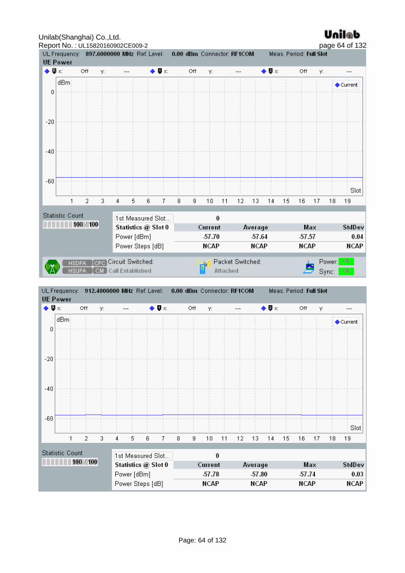
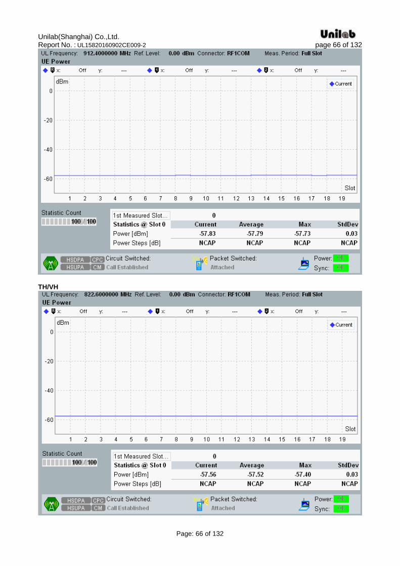
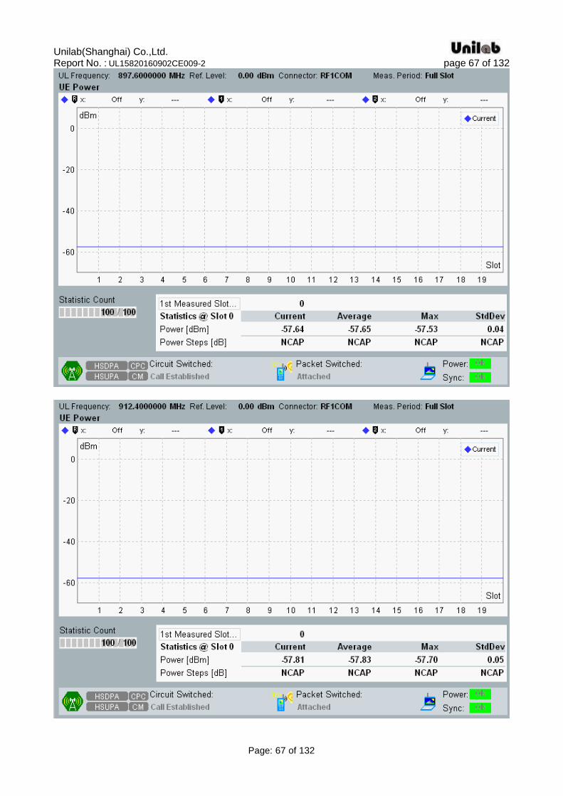
4.4. Transmitter minimum output power Standard Applicable
According to ETSI EN 301 908-2 V7.1.1(2013-10) §4.2.5, The minimum controlled output power of the UE is when the power is set to a minimum value. The minimum transmit power is defined as a mean power in one time slot. Limits The minimum output power shall be less than -49 dBm.
Test procedure 1) Set and send continuously Down power control commands to the UE. 2) Measure the mean power of the UE. Test Result
Band Test
Environment
Transmitter maximum output power (dBm)
Low Channel
Middle Channel
High Channel
Result
WCDMA Band I
normal -56.78 -57.21 -57.33 Pass
TL/VL -56.73 -57.29 -56.98 Pass
TL/VH -56.73 -57.30 -56.84 Pass
TH/VL -56.77 -57.31 -56.96 Pass
TH/VH -56.77 -57.30 -57.06 Pass
WCDMA Band VIII
normal -57.50 -57.65 -57.81 Pass
TL/VL -57.56 -57.66 -57.85 Pass
TL/VH -57.54 -57.70 -57.78 Pass
TH/VL -57.52 -57.58 -57.83 Pass
TH/VH -57.56 -57.64 -57.81 Pass
Please refer to the following data plots.
Unilab(Shanghai) Co.,Ltd. Report No. : UL15820160902CE009-2 page 53 of 132
Page: 53 of 132
WCDMA Band I
normal

Unilab(Shanghai) Co.,Ltd. Report No. : UL15820160902CE009-2 page 54 of 132
Page: 54 of 132
TL/VL

Unilab(Shanghai) Co.,Ltd. Report No. : UL15820160902CE009-2 page 55 of 132
Page: 55 of 132
Unilab(Shanghai) Co.,Ltd. Report No. : UL15820160902CE009-2 page 56 of 132
Page: 56 of 132
TL/VH
Unilab(Shanghai) Co.,Ltd. Report No. : UL15820160902CE009-2 page 57 of 132
Page: 57 of 132
TH/VL

Unilab(Shanghai) Co.,Ltd. Report No. : UL15820160902CE009-2 page 58 of 132
Page: 58 of 132
Unilab(Shanghai) Co.,Ltd. Report No. : UL15820160902CE009-2 page 59 of 132
Page: 59 of 132
TH/VH
Unilab(Shanghai) Co.,Ltd. Report No. : UL15820160902CE009-2 page 60 of 132
Page: 60 of 132
WCDMA Band VIII normal
Unilab(Shanghai) Co.,Ltd. Report No. : UL15820160902CE009-2 page 61 of 132
Page: 61 of 132
Unilab(Shanghai) Co.,Ltd. Report No. : UL15820160902CE009-2 page 62 of 132
Page: 62 of 132
TL/VL
Unilab(Shanghai) Co.,Ltd. Report No. : UL15820160902CE009-2 page 63 of 132
Page: 63 of 132
TL/VH
Unilab(Shanghai) Co.,Ltd. Report No. : UL15820160902CE009-2 page 64 of 132
Page: 64 of 132

Unilab(Shanghai) Co.,Ltd. Report No. : UL15820160902CE009-2 page 65 of 132
Page: 65 of 132
TH/VL
Unilab(Shanghai) Co.,Ltd. Report No. : UL15820160902CE009-2 page 66 of 132
Page: 66 of 132
TH/VH
Unilab(Shanghai) Co.,Ltd. Report No. : UL15820160902CE009-2 page 67 of 132
Page: 67 of 132
Unilab(Shanghai) Co.,Ltd. Report No. : UL15820160902CE009-2 page 68 of 132
Page: 68 of 132
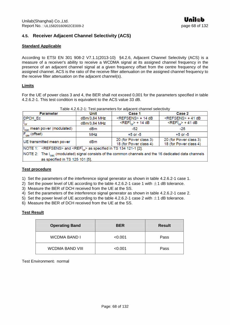
4.5. Receiver Adjacent Channel Selectivity (ACS) Standard Applicable
According to ETSI EN 301 908-2 V7.1.1(2013-10) §4.2.6, Adjacent Channel Selectivity (ACS) is a measure of a receiver's ability to receive a WCDMA signal at its assigned channel frequency in the presence of an adjacent channel signal at a given frequency offset from the centre frequency of the assigned channel. ACS is the ratio of the receive filter attenuation on the assigned channel frequency to the receive filter attenuation on the adjacent channel(s). Limits For the UE of power class 3 and 4, the BER shall not exceed 0,001 for the parameters specified in table 4.2.6.2-1. This test condition is equivalent to the ACS value 33 dB.
Table 4.2.6.2-1: Test parameters for adjacent channel selectivity
Test procedure 1) Set the parameters of the interference signal generator as shown in table 4.2.6.2-1 case 1.
2) Set the power level of UE according to the table 4.2.6.2-1 case 1 with ±1 dB tolerance.
3) Measure the BER of DCH received from the UE at the SS. 4) Set the parameters of the interference signal generator as shown in table 4.2.6.2-1 case 2.
5) Set the power level of UE according to the table 4.2.6.2-1 case 2 with ±1 dB tolerance.
6) Measure the BER of DCH received from the UE at the SS. Test Result
Operating Band BER Result
WCDMA BAND I <0.001 Pass
WCDMA BAND VIII <0.001 Pass
Test Environment: normal
Unilab(Shanghai) Co.,Ltd. Report No. : UL15820160902CE009-2 page 69 of 132
Page: 69 of 132
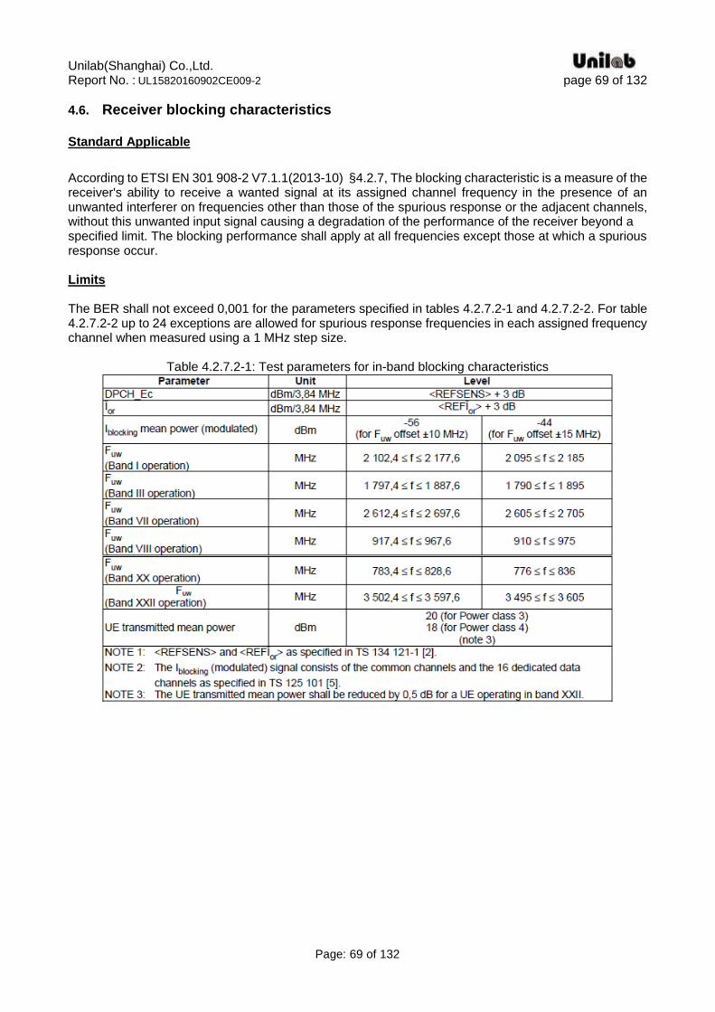
4.6. Receiver blocking characteristics Standard Applicable
According to ETSI EN 301 908-2 V7.1.1(2013-10) §4.2.7, The blocking characteristic is a measure of the receiver's ability to receive a wanted signal at its assigned channel frequency in the presence of an unwanted interferer on frequencies other than those of the spurious response or the adjacent channels, without this unwanted input signal causing a degradation of the performance of the receiver beyond a specified limit. The blocking performance shall apply at all frequencies except those at which a spurious response occur. Limits The BER shall not exceed 0,001 for the parameters specified in tables 4.2.7.2-1 and 4.2.7.2-2. For table 4.2.7.2-2 up to 24 exceptions are allowed for spurious response frequencies in each assigned frequency channel when measured using a 1 MHz step size.
Table 4.2.7.2-1: Test parameters for in-band blocking characteristics
Unilab(Shanghai) Co.,Ltd. Report No. : UL15820160902CE009-2 page 70 of 132
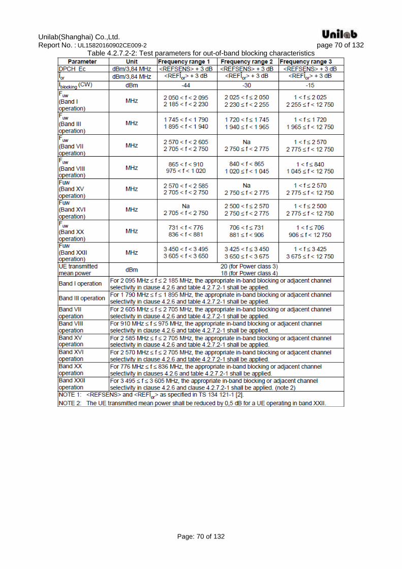
Page: 70 of 132
Table 4.2.7.2-2: Test parameters for out-of-band blocking characteristics
Unilab(Shanghai) Co.,Ltd. Report No. : UL15820160902CE009-2 page 71 of 132
Page: 71 of 132
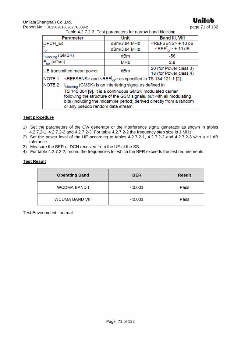
Table 4.2.7.2-3: Test parameters for narrow band blocking
Test procedure 1) Set the parameters of the CW generator or the interference signal generator as shown in tables
4.2.7.2-1, 4.2.7.2-2 and 4.2.7.2-3. For table 4.2.7.2-2 the frequency step size is 1 MHz. 2) Set the power level of the UE according to tables 4.2.7.2-1, 4.2.7.2-2 and 4.2.7.2-3 with a ±1 dB
tolerance. 3) Measure the BER of DCH received from the UE at the SS. 4) For table 4.2.7.2-2, record the frequencies for which the BER exceeds the test requirements. Test Result
Operating Band BER Result
WCDMA BAND I <0.001 Pass
WCDMA BAND VIII <0.001 Pass
Test Environment: normal
Unilab(Shanghai) Co.,Ltd. Report No. : UL15820160902CE009-2 page 72 of 132
Page: 72 of 132
4.7. Receiver spurious response
Standard Applicable
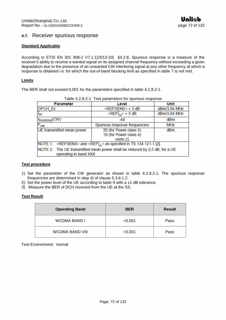
According to ETSI EN 301 908-2 V7.1.1(2013-10) §4.2.8, Spurious response is a measure of the receiver's ability to receive a wanted signal on its assigned channel frequency without exceeding a given degradation due to the presence of an unwanted CW interfering signal at any other frequency at which a response is obtained i.e. for which the out-of-band blocking limit as specified in table 7 is not met. Limits The BER shall not exceed 0,001 for the parameters specified in table 4.2.8.2-1.
Table 4.2.8.2-1: Test parameters for spurious response
Test procedure 1) Set the parameter of the CW generator as shown in table 4.2.8.2-1. The spurious response
frequencies are determined in step 4) of clause 5.3.6.1.2. 2) Set the power level of the UE according to table 9 with a ±1 dB tolerance. 3) Measure the BER of DCH received from the UE at the SS. Test Result
Operating Band BER Result
WCDMA BAND I <0.001 Pass
WCDMA BAND VIII <0.001 Pass
Test Environment: normal
Unilab(Shanghai) Co.,Ltd. Report No. : UL15820160902CE009-2 page 73 of 132
Page: 73 of 132
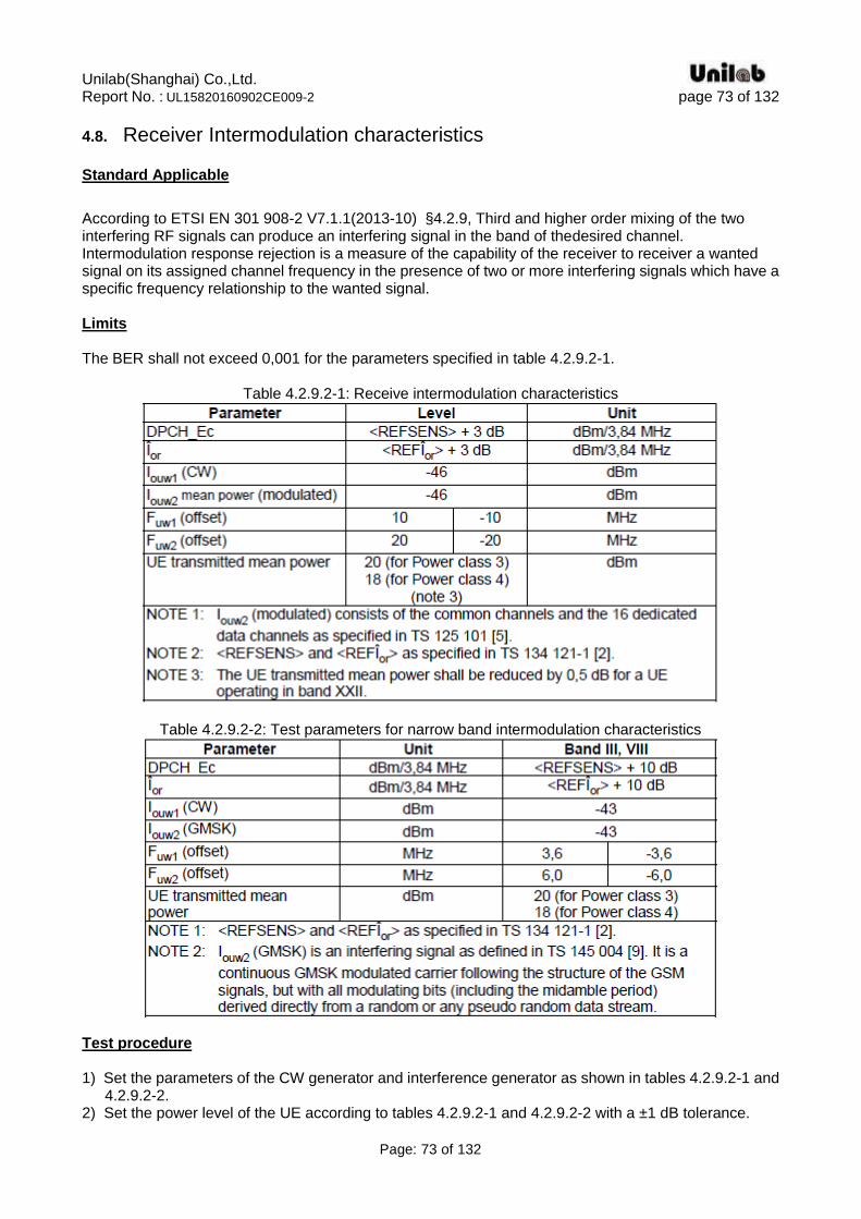
4.8. Receiver Intermodulation characteristics
Standard Applicable
According to ETSI EN 301 908-2 V7.1.1(2013-10) §4.2.9, Third and higher order mixing of the two interfering RF signals can produce an interfering signal in the band of thedesired channel. Intermodulation response rejection is a measure of the capability of the receiver to receiver a wanted signal on its assigned channel frequency in the presence of two or more interfering signals which have a specific frequency relationship to the wanted signal. Limits The BER shall not exceed 0,001 for the parameters specified in table 4.2.9.2-1.
Table 4.2.9.2-1: Receive intermodulation characteristics
Table 4.2.9.2-2: Test parameters for narrow band intermodulation characteristics
Test procedure 1) Set the parameters of the CW generator and interference generator as shown in tables 4.2.9.2-1 and
4.2.9.2-2. 2) Set the power level of the UE according to tables 4.2.9.2-1 and 4.2.9.2-2 with a ±1 dB tolerance.
Unilab(Shanghai) Co.,Ltd. Report No. : UL15820160902CE009-2 page 74 of 132
Page: 74 of 132
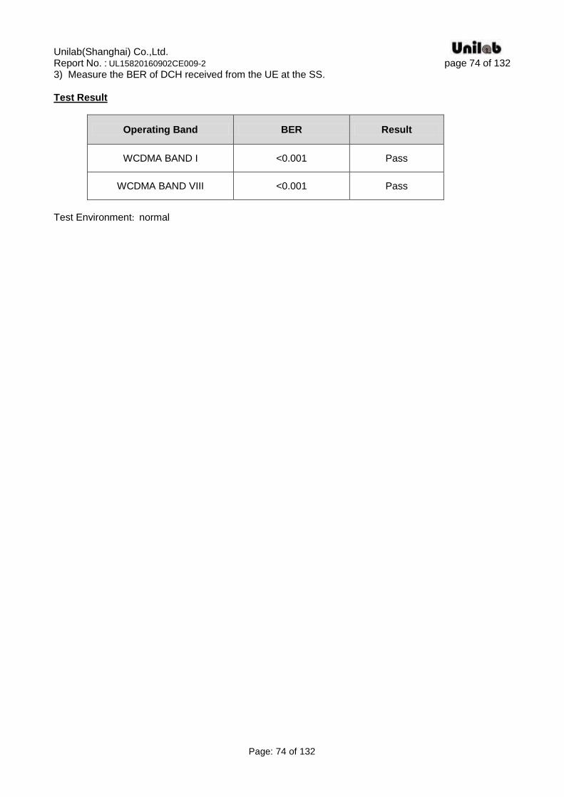
3) Measure the BER of DCH received from the UE at the SS. Test Result
Operating Band BER Result
WCDMA BAND I <0.001 Pass
WCDMA BAND VIII <0.001 Pass
Test Environment: normal
Unilab(Shanghai) Co.,Ltd. Report No. : UL15820160902CE009-2 page 75 of 132
Page: 75 of 132
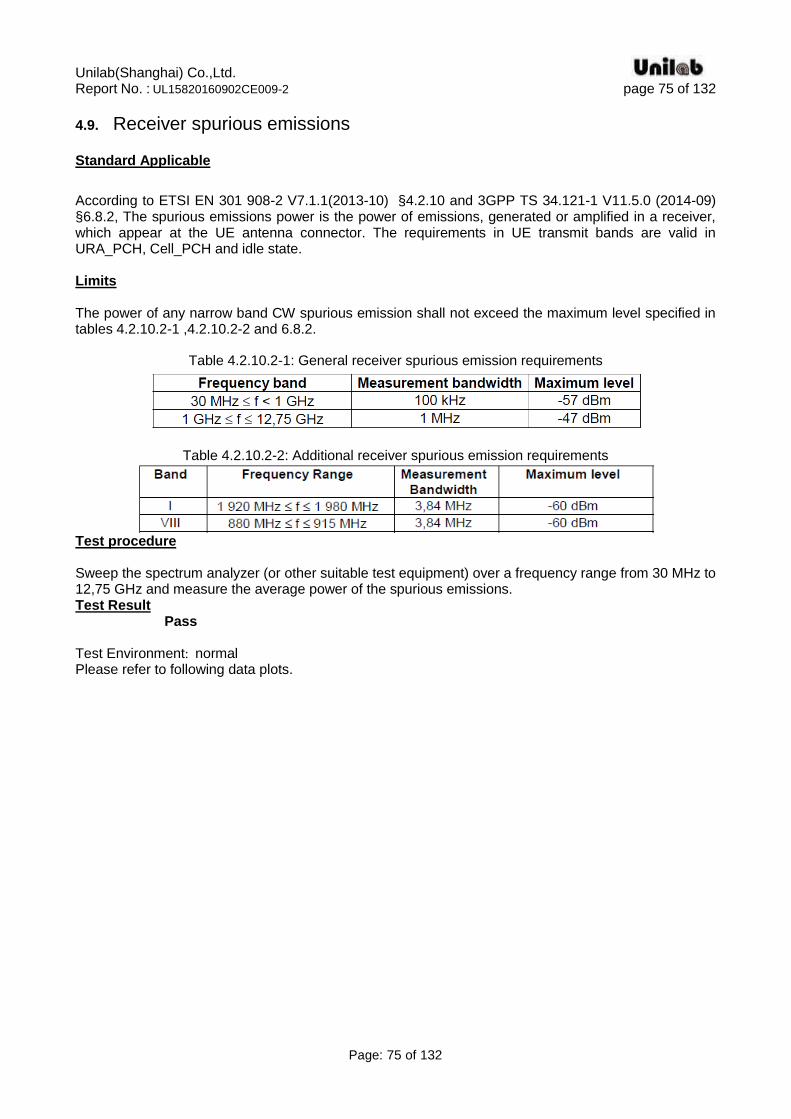
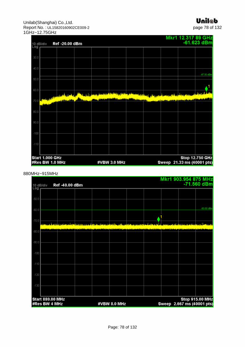
4.9. Receiver spurious emissions
Standard Applicable
According to ETSI EN 301 908-2 V7.1.1(2013-10) §4.2.10 and 3GPP TS 34.121-1 V11.5.0 (2014-09) §6.8.2, The spurious emissions power is the power of emissions, generated or amplified in a receiver, which appear at the UE antenna connector. The requirements in UE transmit bands are valid in URA_PCH, Cell_PCH and idle state. Limits The power of any narrow band CW spurious emission shall not exceed the maximum level specified in tables 4.2.10.2-1 ,4.2.10.2-2 and 6.8.2.
Table 4.2.10.2-1: General receiver spurious emission requirements
Table 4.2.10.2-2: Additional receiver spurious emission requirements
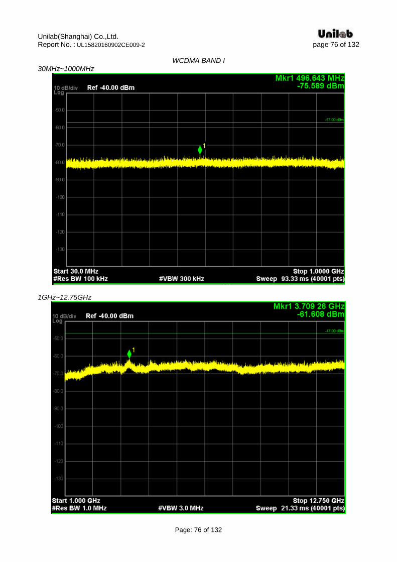
Test procedure Sweep the spectrum analyzer (or other suitable test equipment) over a frequency range from 30 MHz to 12,75 GHz and measure the average power of the spurious emissions. Test Result Pass Test Environment: normal Please refer to following data plots.
Unilab(Shanghai) Co.,Ltd. Report No. : UL15820160902CE009-2 page 76 of 132
Page: 76 of 132
WCDMA BAND I
30MHz~1000MHz
1GHz~12.75GHz

Unilab(Shanghai) Co.,Ltd. Report No. : UL15820160902CE009-2 page 77 of 132
Page: 77 of 132
1920MHz~1980MHz
WCDMA BAND VIII 30MHz~1000MHz
Unilab(Shanghai) Co.,Ltd. Report No. : UL15820160902CE009-2 page 78 of 132
Page: 78 of 132
1GHz~12.75GHz
880MHz~915MHz
Unilab(Shanghai) Co.,Ltd. Report No. : UL15820160902CE009-2 page 79 of 132
Page: 79 of 132
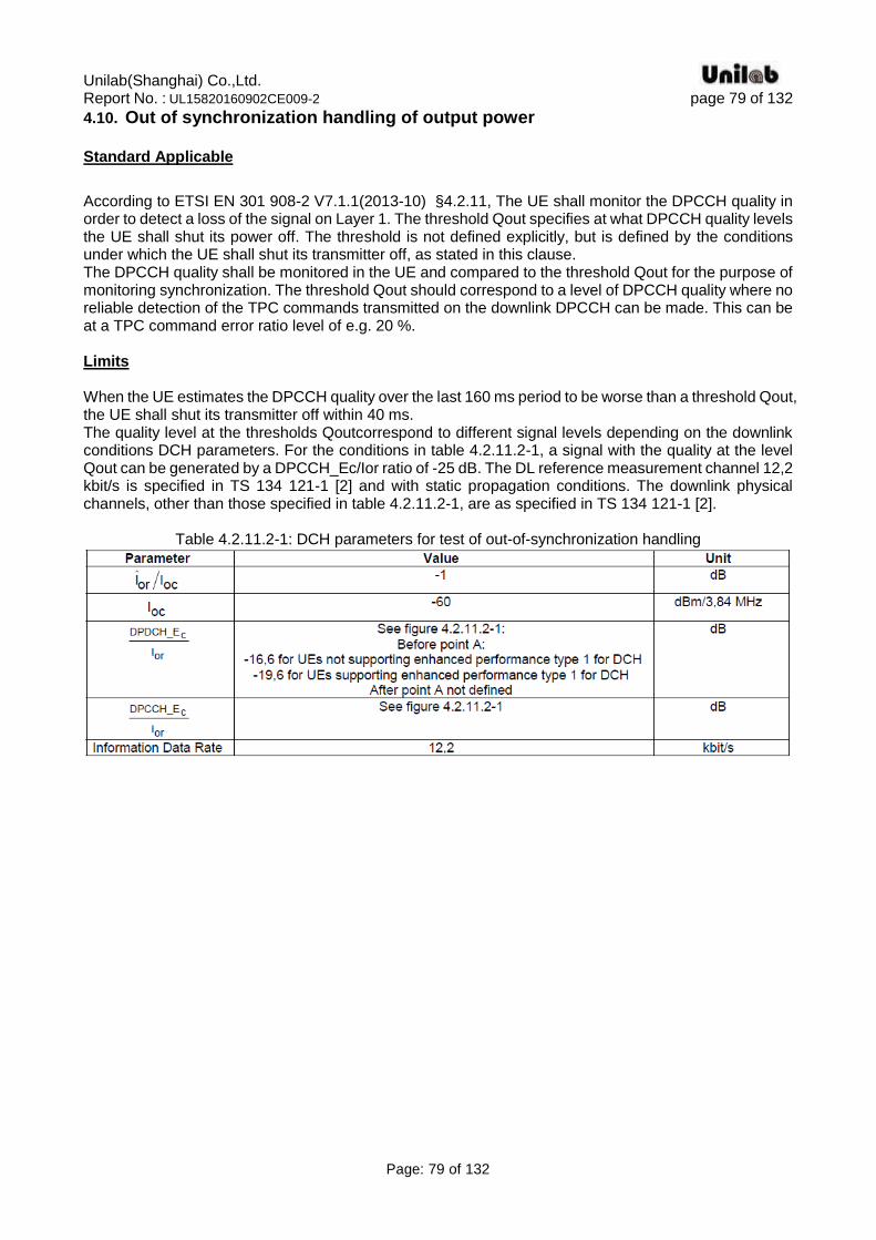
4.10. Out of synchronization handling of output power Standard Applicable
According to ETSI EN 301 908-2 V7.1.1(2013-10) §4.2.11, The UE shall monitor the DPCCH quality in order to detect a loss of the signal on Layer 1. The threshold Qout specifies at what DPCCH quality levels the UE shall shut its power off. The threshold is not defined explicitly, but is defined by the conditions under which the UE shall shut its transmitter off, as stated in this clause. The DPCCH quality shall be monitored in the UE and compared to the threshold Qout for the purpose of monitoring synchronization. The threshold Qout should correspond to a level of DPCCH quality where no reliable detection of the TPC commands transmitted on the downlink DPCCH can be made. This can be at a TPC command error ratio level of e.g. 20 %. Limits When the UE estimates the DPCCH quality over the last 160 ms period to be worse than a threshold Qout, the UE shall shut its transmitter off within 40 ms. The quality level at the thresholds Qoutcorrespond to different signal levels depending on the downlink conditions DCH parameters. For the conditions in table 4.2.11.2-1, a signal with the quality at the level Qout can be generated by a DPCCH_Ec/Ior ratio of -25 dB. The DL reference measurement channel 12,2 kbit/s is specified in TS 134 121-1 [2] and with static propagation conditions. The downlink physical channels, other than those specified in table 4.2.11.2-1, are as specified in TS 134 121-1 [2].
Table 4.2.11.2-1: DCH parameters for test of out-of-synchronization handling
Unilab(Shanghai) Co.,Ltd. Report No. : UL15820160902CE009-2 page 80 of 132
Page: 80 of 132
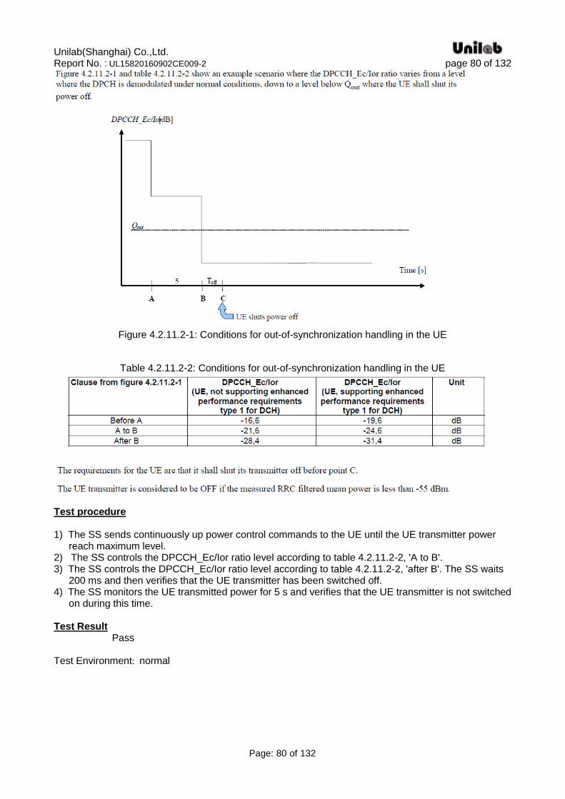
Figure 4.2.11.2-1: Conditions for out-of-synchronization handling in the UE
Table 4.2.11.2-2: Conditions for out-of-synchronization handling in the UE
Test procedure 1) The SS sends continuously up power control commands to the UE until the UE transmitter power
reach maximum level. 2) The SS controls the DPCCH_Ec/Ior ratio level according to table 4.2.11.2-2, 'A to B'. 3) The SS controls the DPCCH_Ec/Ior ratio level according to table 4.2.11.2-2, 'after B'. The SS waits
200 ms and then verifies that the UE transmitter has been switched off. 4) The SS monitors the UE transmitted power for 5 s and verifies that the UE transmitter is not switched
on during this time. Test Result Pass Test Environment: normal
Unilab(Shanghai) Co.,Ltd. Report No. : UL15820160902CE009-2 page 81 of 132
Page: 81 of 132
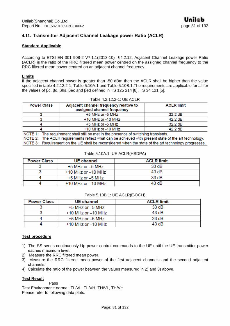
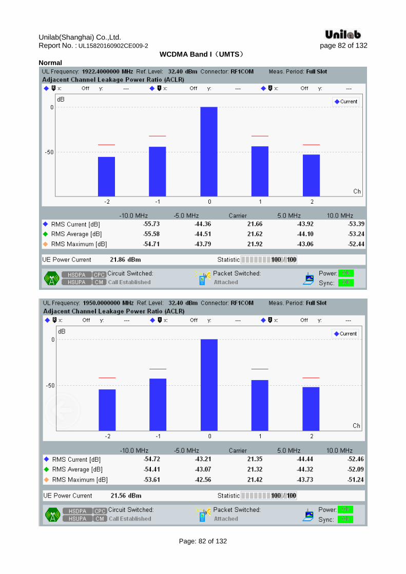
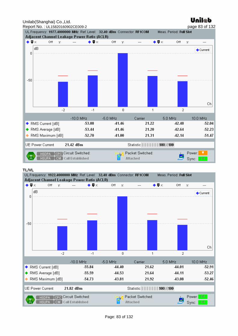
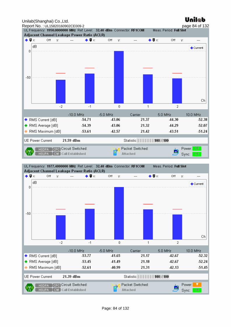
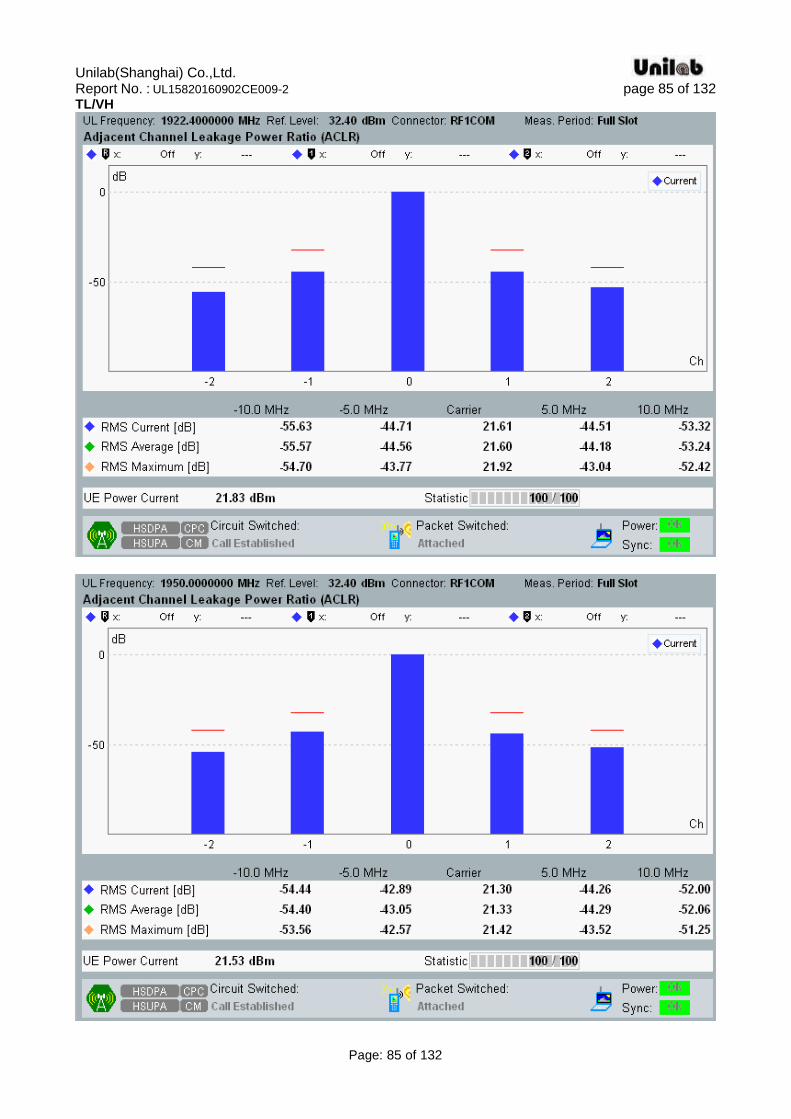
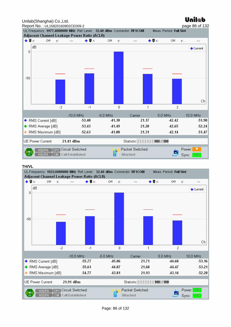
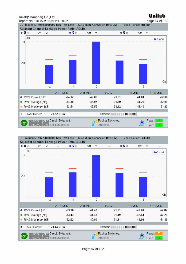
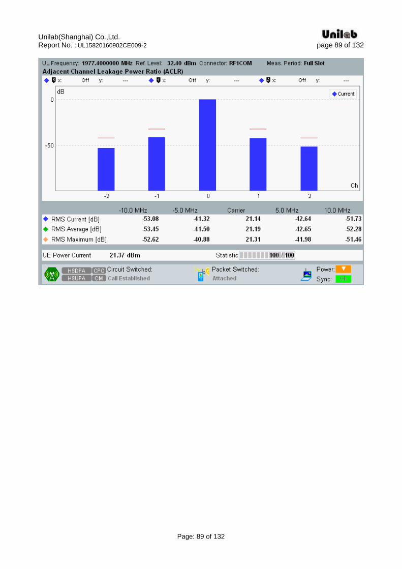
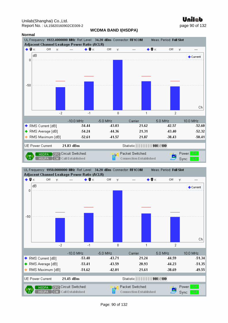
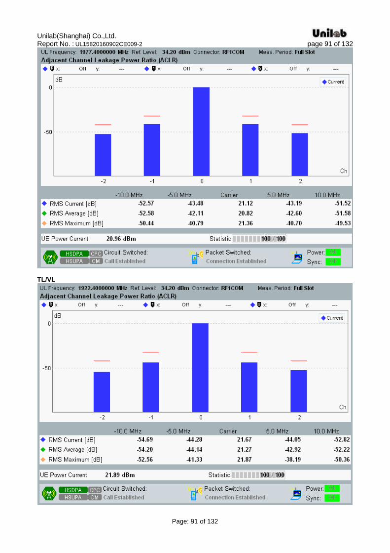
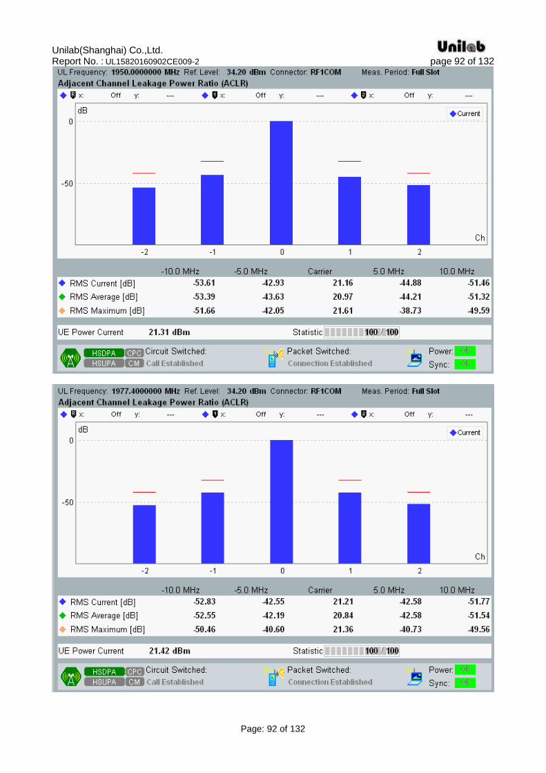
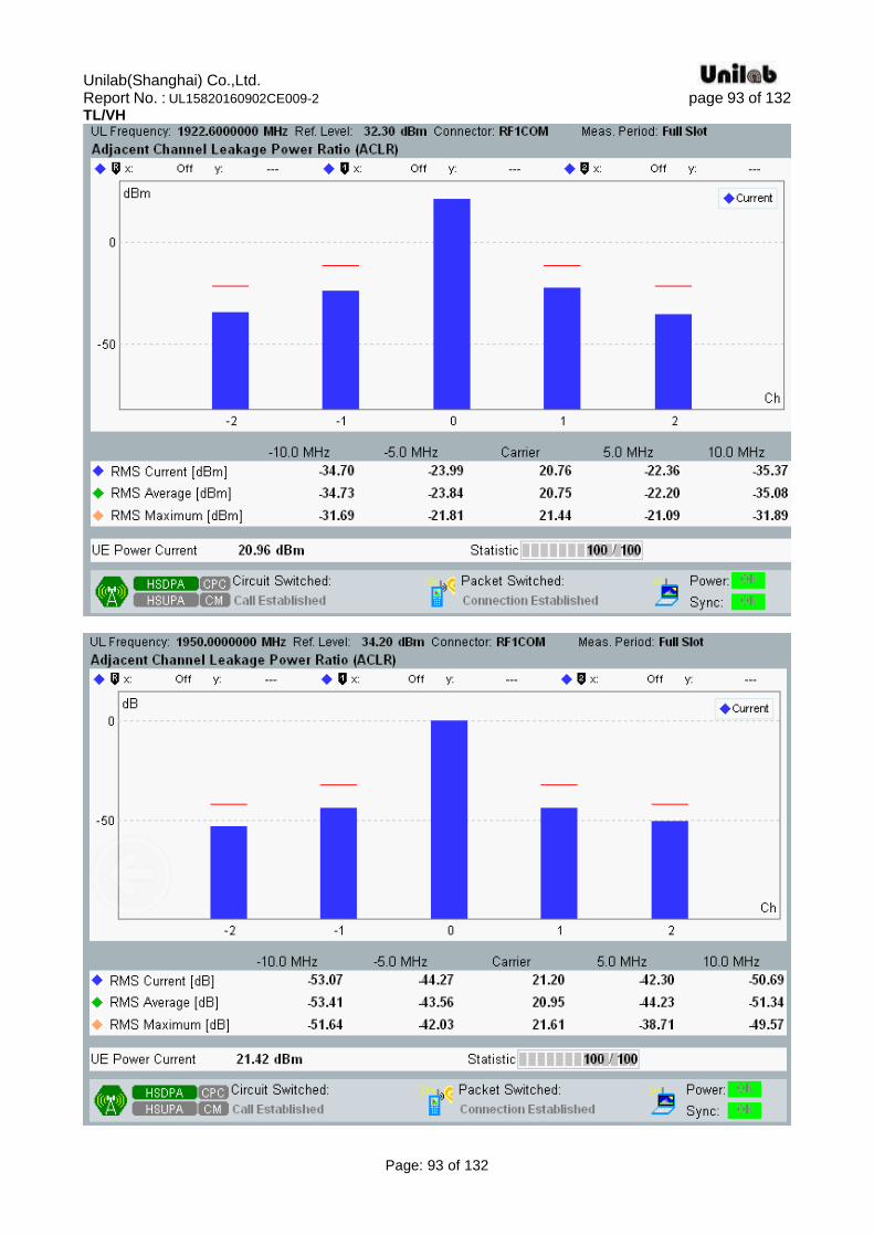
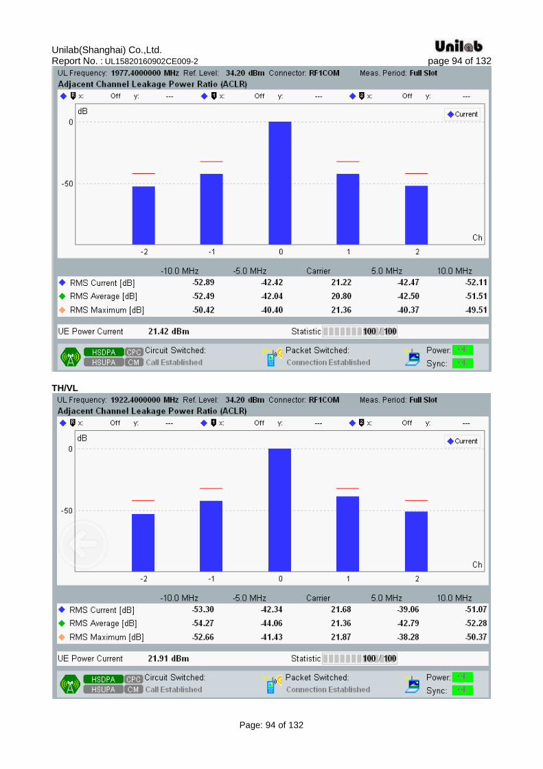
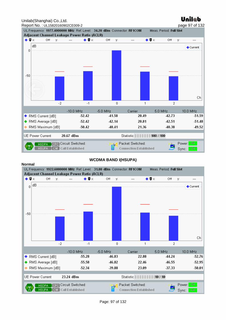
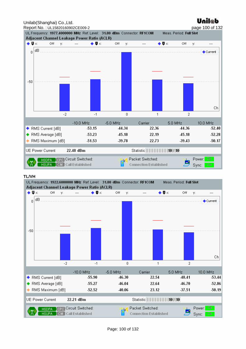
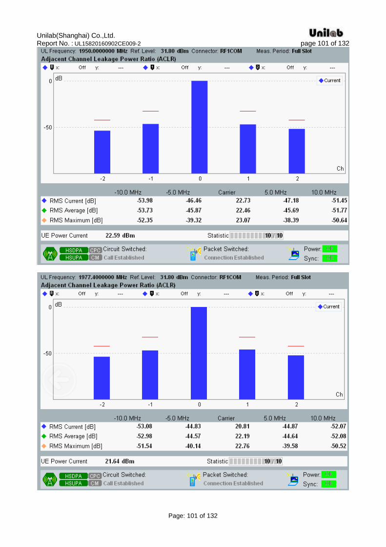
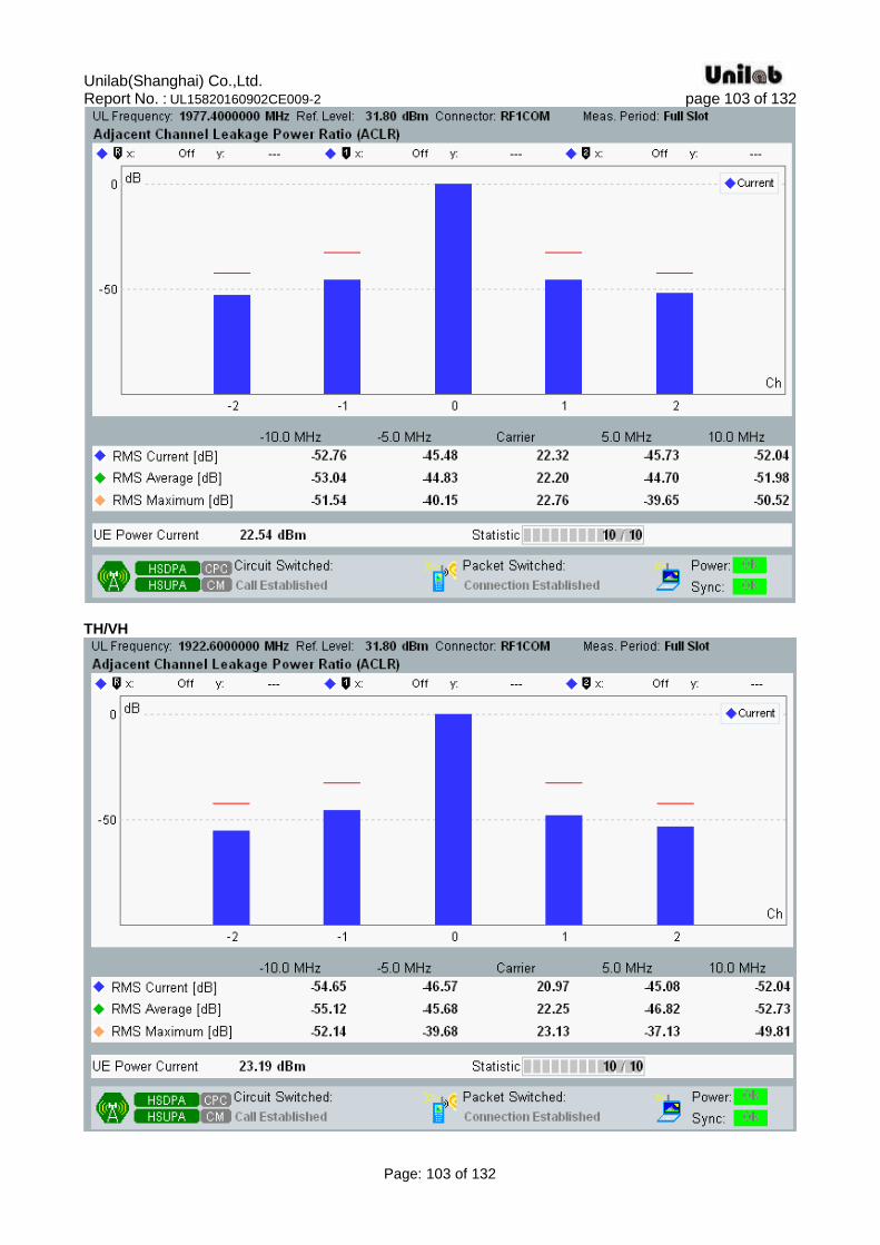
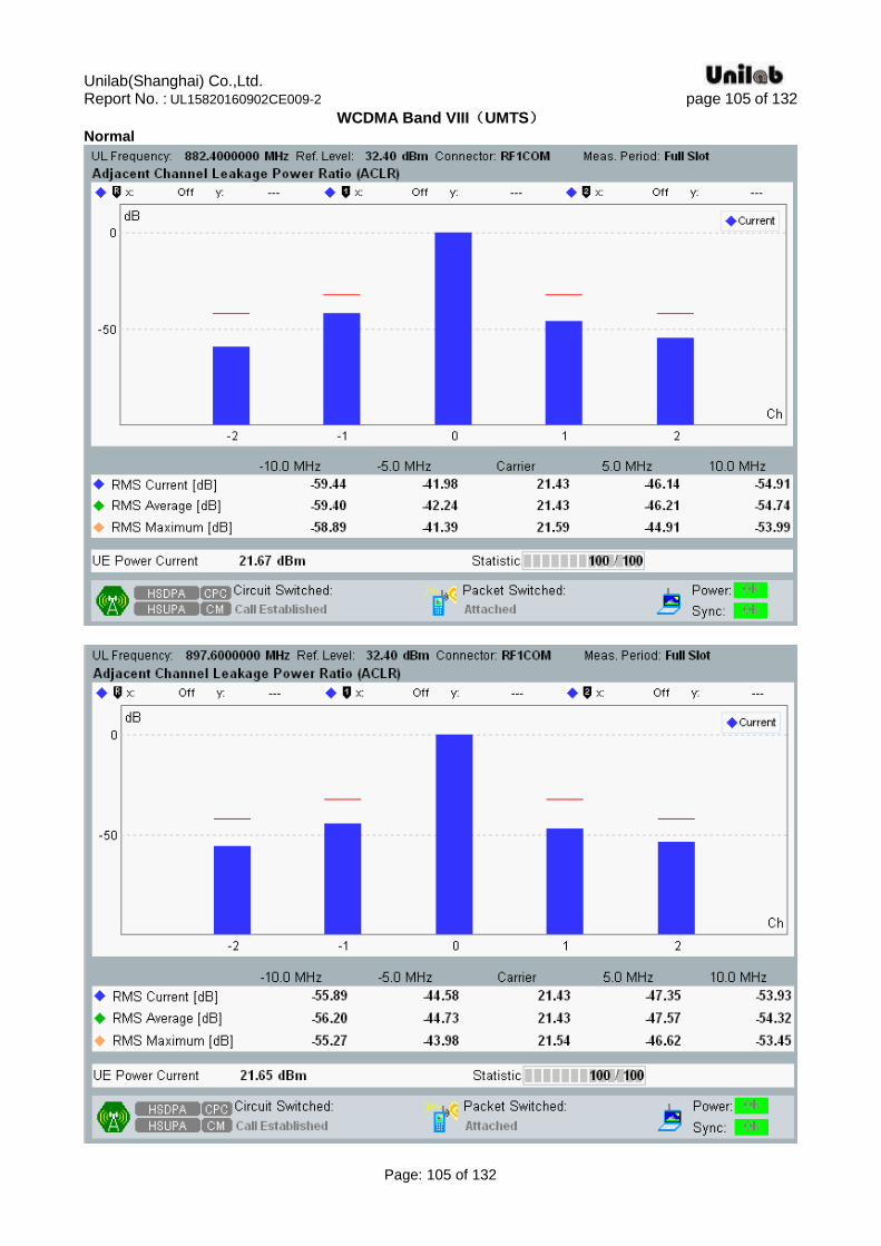
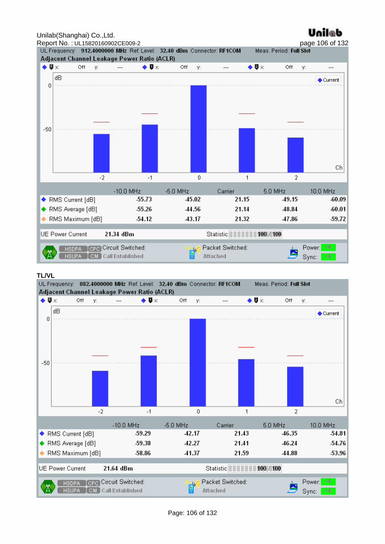
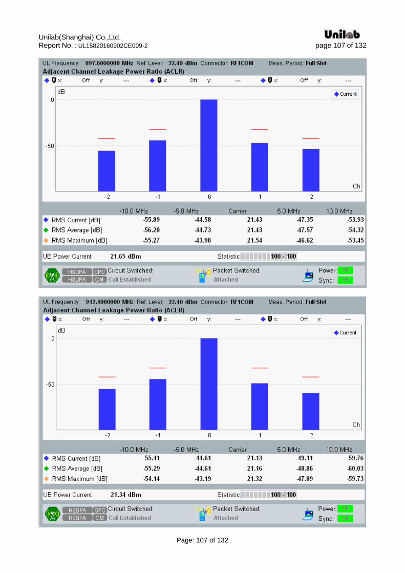
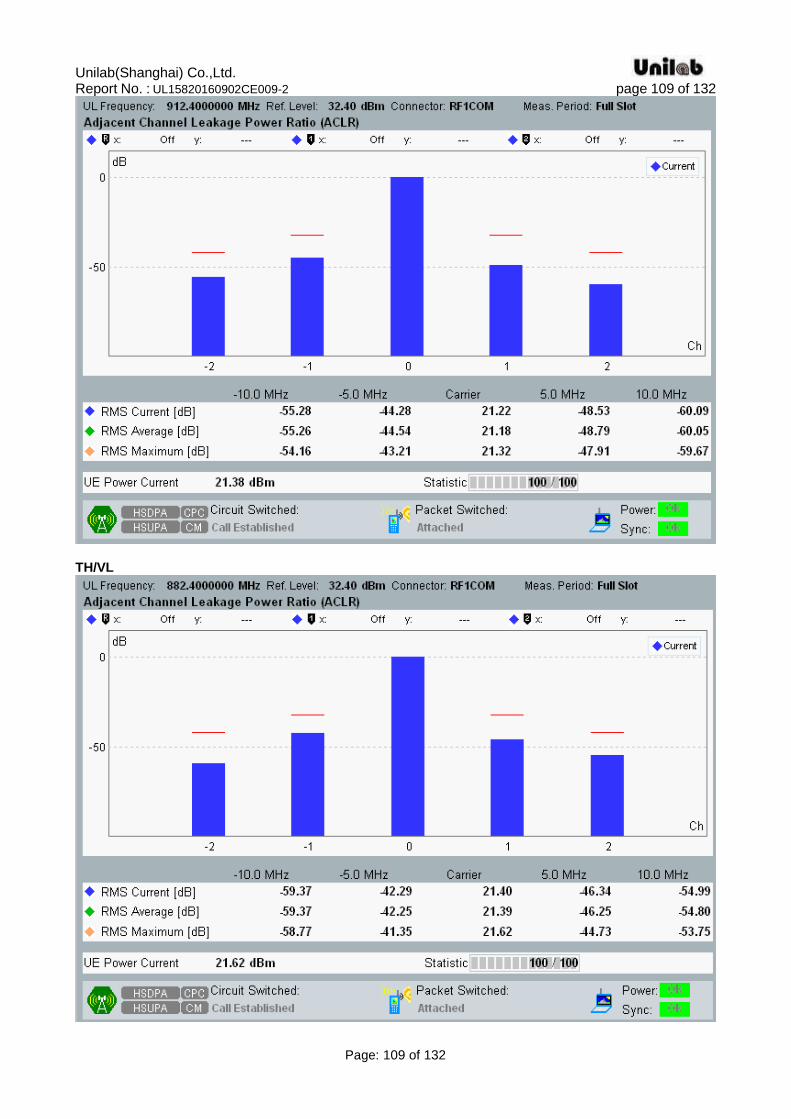
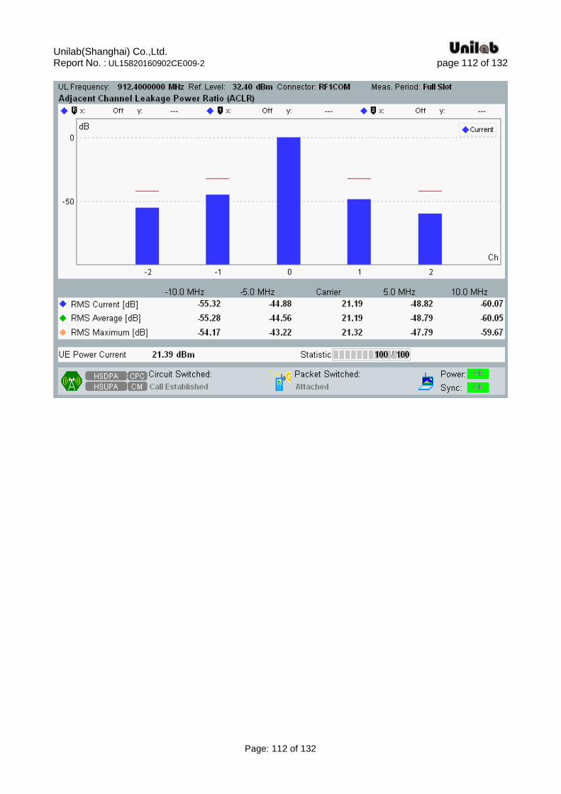
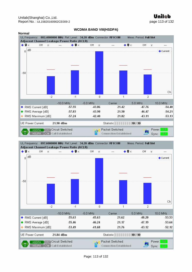
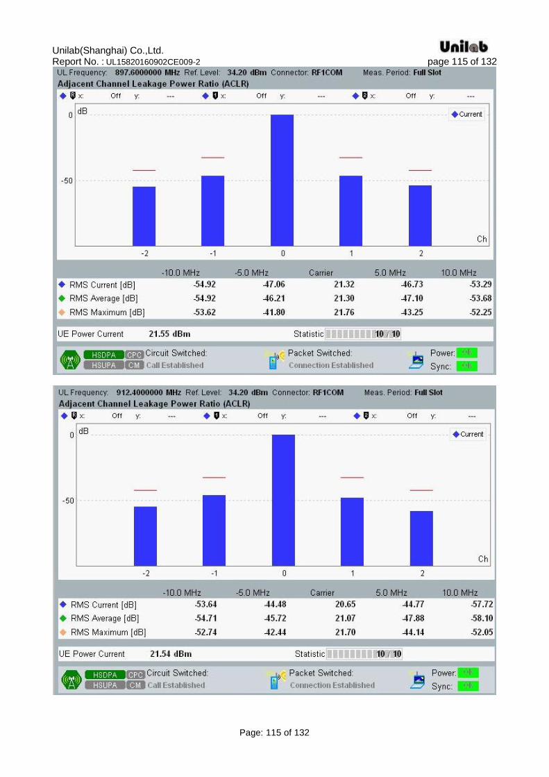
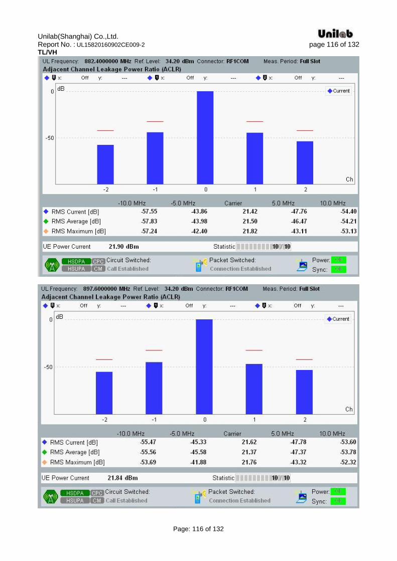
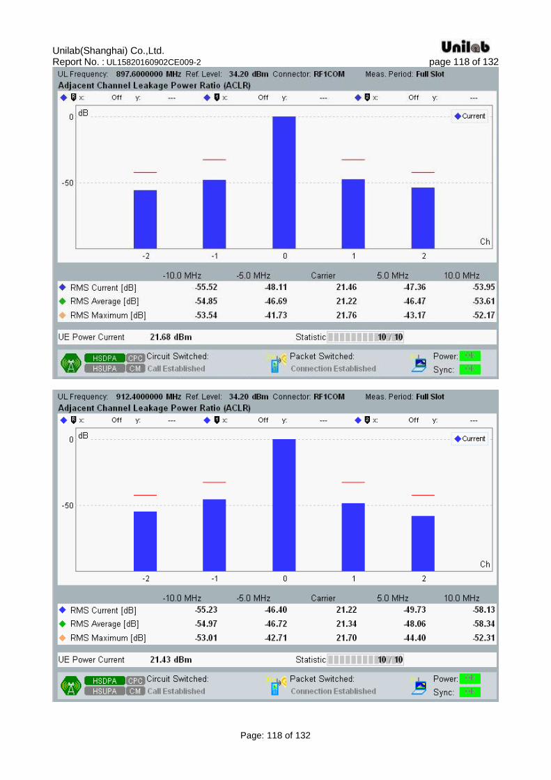
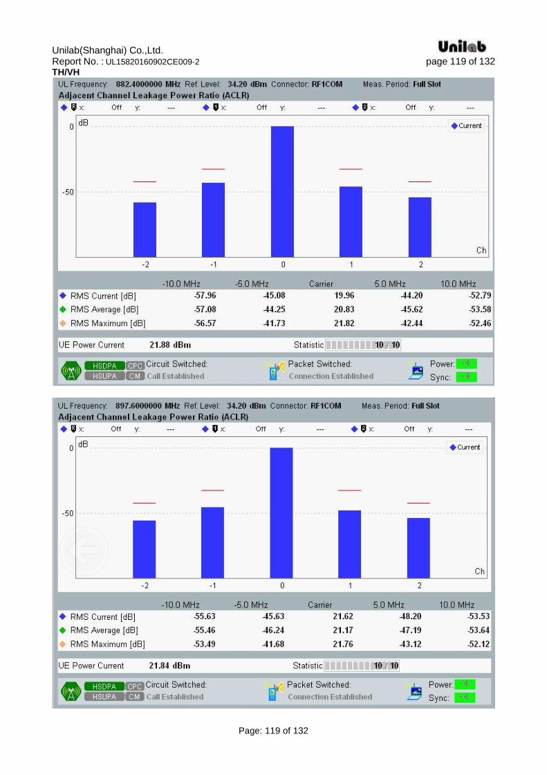
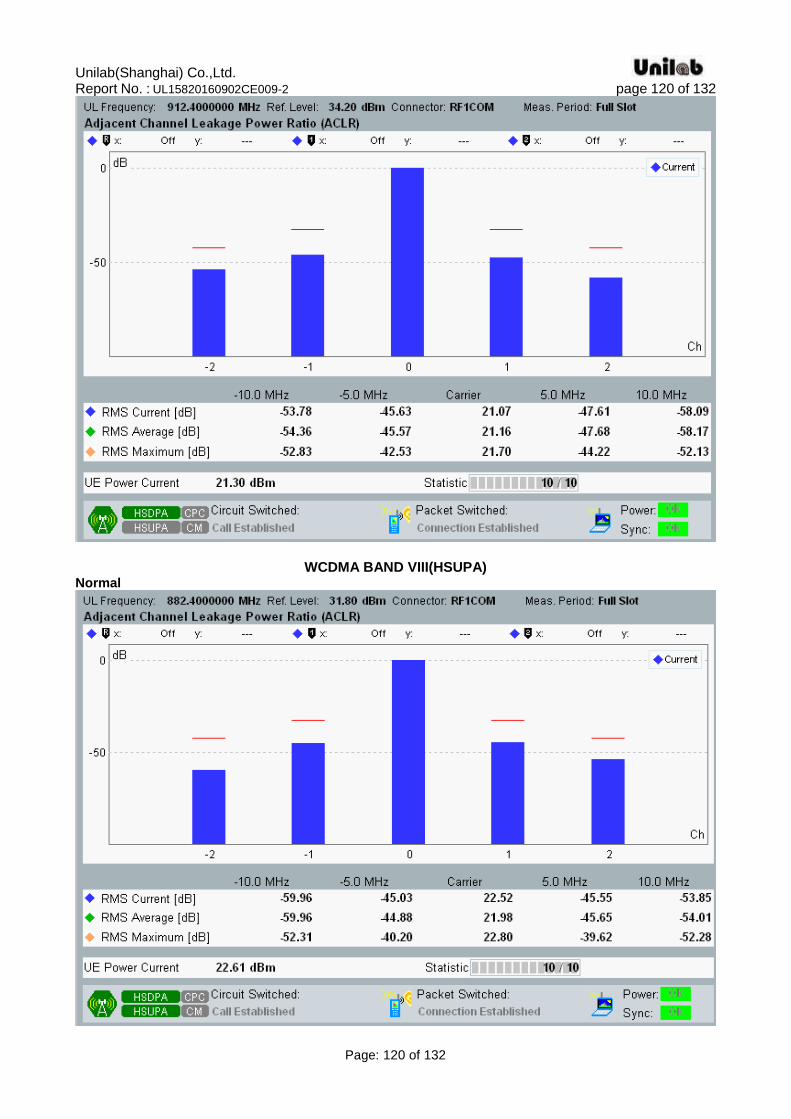
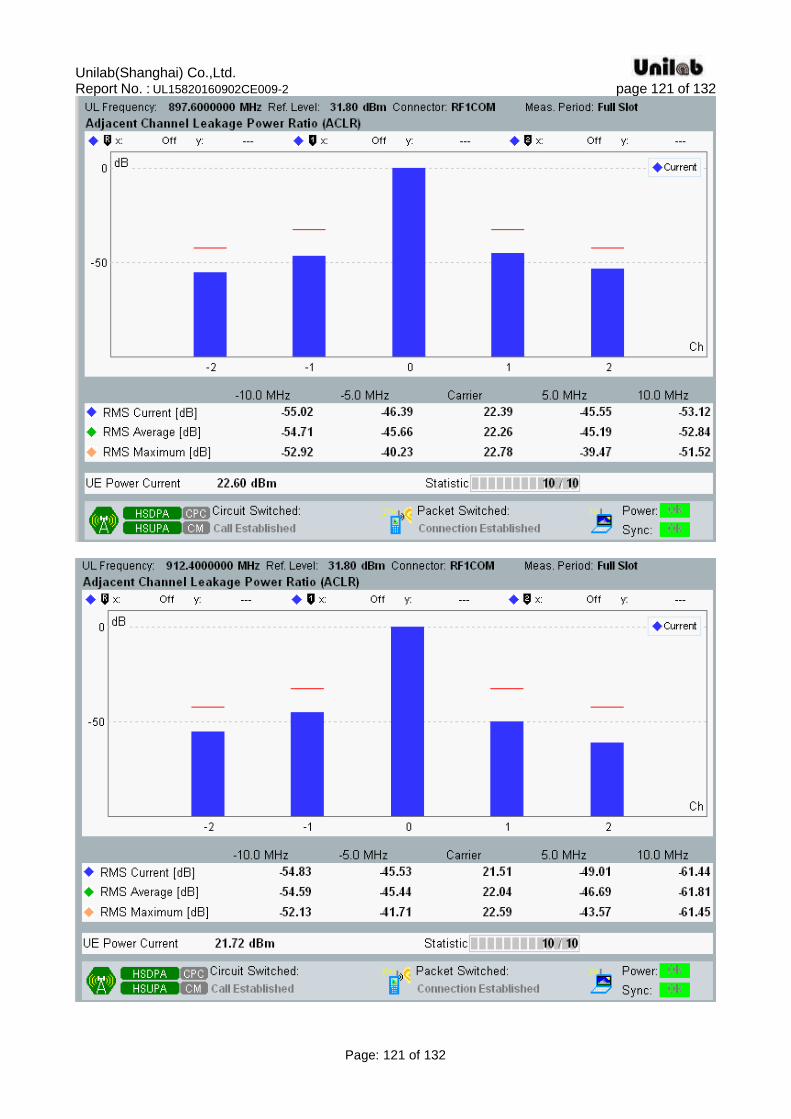
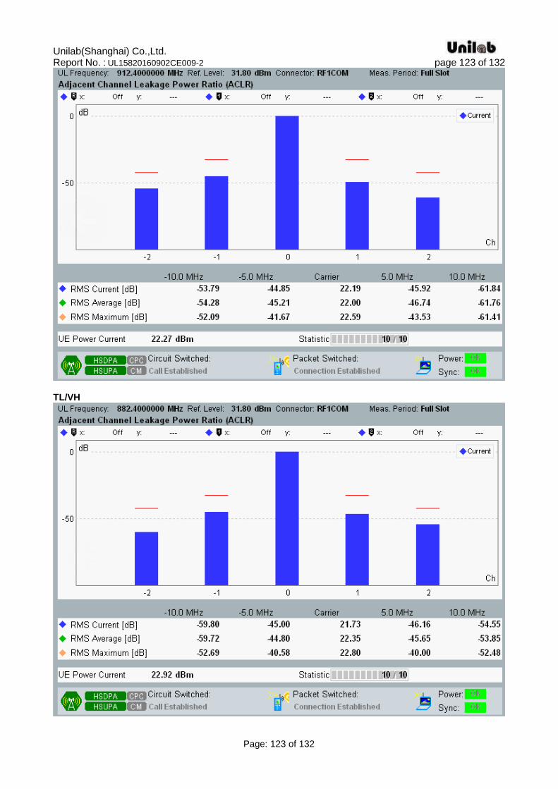
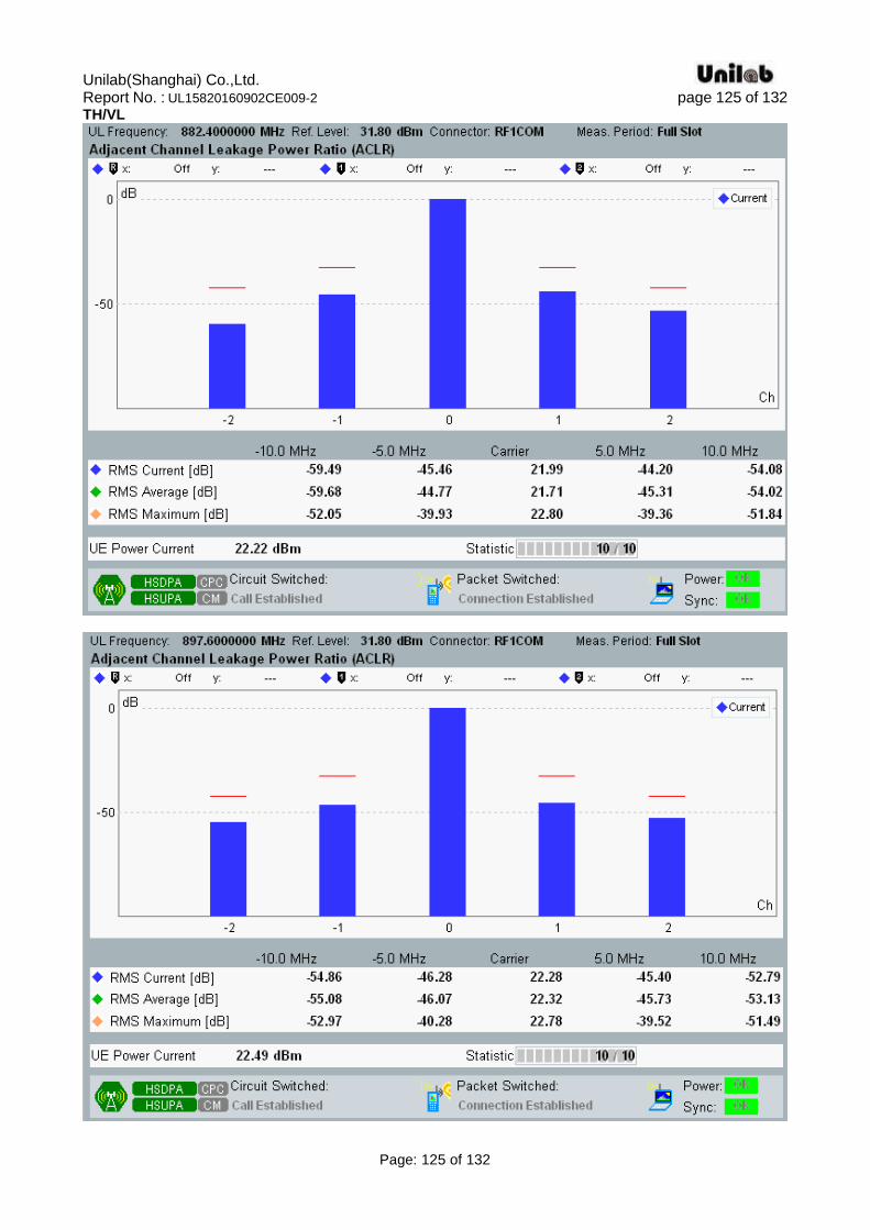
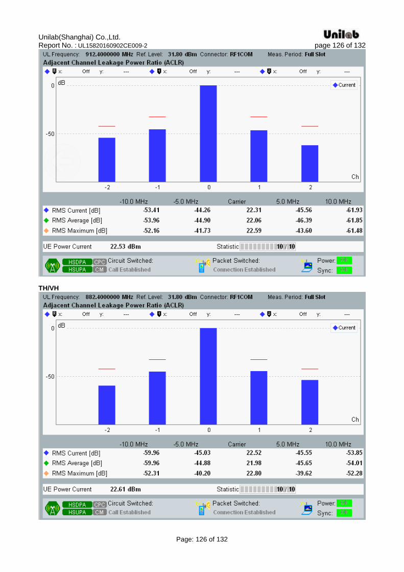
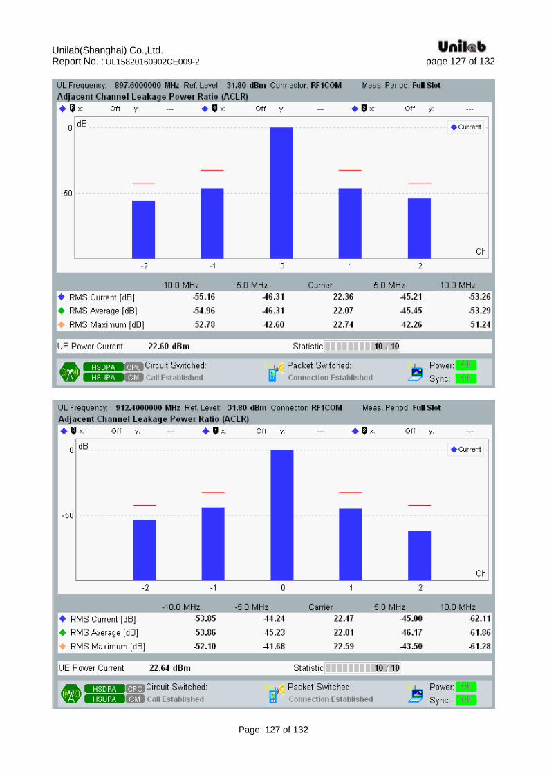
4.11. Transmitter Adjacent Channel Leakage power Ratio (ACLR) Standard Applicable
According to ETSI EN 301 908-2 V7.1.1(2013-10) §4.2.12, Adjacent Channel Leakage power Ratio (ACLR) is the ratio of the RRC filtered mean power centred on the assigned channel frequency to the RRC filtered mean power centred on an adjacent channel frequency. Limits If the adjacent channel power is greater than -50 dBm then the ACLR shall be higher than the value specified in table 4.2.12.2-1, Table 5.10A.1 and Table 5.10B.1.The requirements are applicable for all for the values of βc, βd, βhs, βec and βed defined in TS 125 214 [8], TS 34 121 [5].
Table 4.2.12.2-1: UE ACLR
Table 5.10A.1: UE ACLR(HSDPA)
Table 5.10B.1: UE ACLR(E-DCH)
Test procedure 1) The SS sends continuously Up power control commands to the UE until the UE transmitter power
eaches maximum level. 2) Measure the RRC filtered mean power. 3) Measure the RRC filtered mean power of the first adjacent channels and the second adjacent
channels. 4) Calculate the ratio of the power between the values measured in 2) and 3) above. Test Result Pass Test Environment: normal, TL/VL, TL/VH, TH/VL, TH/VH Please refer to following data plots.
Unilab(Shanghai) Co.,Ltd. Report No. : UL15820160902CE009-2 page 82 of 132
Page: 82 of 132
WCDMA Band I(UMTS) Normal
Unilab(Shanghai) Co.,Ltd. Report No. : UL15820160902CE009-2 page 83 of 132
Page: 83 of 132
TL/VL
Unilab(Shanghai) Co.,Ltd. Report No. : UL15820160902CE009-2 page 84 of 132
Page: 84 of 132
Unilab(Shanghai) Co.,Ltd. Report No. : UL15820160902CE009-2 page 85 of 132
Page: 85 of 132
TL/VH
Unilab(Shanghai) Co.,Ltd. Report No. : UL15820160902CE009-2 page 86 of 132
Page: 86 of 132
TH/VL
Unilab(Shanghai) Co.,Ltd. Report No. : UL15820160902CE009-2 page 87 of 132
Page: 87 of 132

Unilab(Shanghai) Co.,Ltd. Report No. : UL15820160902CE009-2 page 88 of 132
Page: 88 of 132
TH/VH
Unilab(Shanghai) Co.,Ltd. Report No. : UL15820160902CE009-2 page 89 of 132
Page: 89 of 132
Unilab(Shanghai) Co.,Ltd. Report No. : UL15820160902CE009-2 page 90 of 132
Page: 90 of 132
WCDMA BAND I(HSDPA) Normal
Unilab(Shanghai) Co.,Ltd. Report No. : UL15820160902CE009-2 page 91 of 132
Page: 91 of 132
TL/VL
Unilab(Shanghai) Co.,Ltd. Report No. : UL15820160902CE009-2 page 92 of 132
Page: 92 of 132
Unilab(Shanghai) Co.,Ltd. Report No. : UL15820160902CE009-2 page 93 of 132
Page: 93 of 132
TL/VH
Unilab(Shanghai) Co.,Ltd. Report No. : UL15820160902CE009-2 page 94 of 132
Page: 94 of 132
TH/VL

Unilab(Shanghai) Co.,Ltd. Report No. : UL15820160902CE009-2 page 95 of 132
Page: 95 of 132

Unilab(Shanghai) Co.,Ltd. Report No. : UL15820160902CE009-2 page 96 of 132
Page: 96 of 132
TH/VH
Unilab(Shanghai) Co.,Ltd. Report No. : UL15820160902CE009-2 page 97 of 132
Page: 97 of 132
WCDMA BAND I(HSUPA) Normal

Unilab(Shanghai) Co.,Ltd. Report No. : UL15820160902CE009-2 page 98 of 132
Page: 98 of 132

Unilab(Shanghai) Co.,Ltd. Report No. : UL15820160902CE009-2 page 99 of 132
Page: 99 of 132
TL/VL
Unilab(Shanghai) Co.,Ltd. Report No. : UL15820160902CE009-2 page 100 of 132
Page: 100 of 132
TL/VH
Unilab(Shanghai) Co.,Ltd. Report No. : UL15820160902CE009-2 page 101 of 132
Page: 101 of 132

Unilab(Shanghai) Co.,Ltd. Report No. : UL15820160902CE009-2 page 102 of 132
Page: 102 of 132
TH/VL
Unilab(Shanghai) Co.,Ltd. Report No. : UL15820160902CE009-2 page 103 of 132
Page: 103 of 132
TH/VH

Unilab(Shanghai) Co.,Ltd. Report No. : UL15820160902CE009-2 page 104 of 132
Page: 104 of 132
Unilab(Shanghai) Co.,Ltd. Report No. : UL15820160902CE009-2 page 105 of 132
Page: 105 of 132
WCDMA Band VIII(UMTS) Normal
Unilab(Shanghai) Co.,Ltd. Report No. : UL15820160902CE009-2 page 106 of 132
Page: 106 of 132
TL/VL
Unilab(Shanghai) Co.,Ltd. Report No. : UL15820160902CE009-2 page 107 of 132
Page: 107 of 132

Unilab(Shanghai) Co.,Ltd. Report No. : UL15820160902CE009-2 page 108 of 132
Page: 108 of 132
TL/VH
Unilab(Shanghai) Co.,Ltd. Report No. : UL15820160902CE009-2 page 109 of 132
Page: 109 of 132
TH/VL

Unilab(Shanghai) Co.,Ltd. Report No. : UL15820160902CE009-2 page 110 of 132
Page: 110 of 132

Unilab(Shanghai) Co.,Ltd. Report No. : UL15820160902CE009-2 page 111 of 132
Page: 111 of 132
TH/VH
Unilab(Shanghai) Co.,Ltd. Report No. : UL15820160902CE009-2 page 112 of 132
Page: 112 of 132
Unilab(Shanghai) Co.,Ltd. Report No. : UL15820160902CE009-2 page 113 of 132
Page: 113 of 132
WCDMA BAND VIII(HSDPA)
Normal

Unilab(Shanghai) Co.,Ltd. Report No. : UL15820160902CE009-2 page 114 of 132
Page: 114 of 132
TL/VL
Unilab(Shanghai) Co.,Ltd. Report No. : UL15820160902CE009-2 page 115 of 132
Page: 115 of 132
Unilab(Shanghai) Co.,Ltd. Report No. : UL15820160902CE009-2 page 116 of 132
Page: 116 of 132
TL/VH

Unilab(Shanghai) Co.,Ltd. Report No. : UL15820160902CE009-2 page 117 of 132
Page: 117 of 132
TH/VL
Unilab(Shanghai) Co.,Ltd. Report No. : UL15820160902CE009-2 page 118 of 132
Page: 118 of 132
Unilab(Shanghai) Co.,Ltd. Report No. : UL15820160902CE009-2 page 119 of 132
Page: 119 of 132
TH/VH
Unilab(Shanghai) Co.,Ltd. Report No. : UL15820160902CE009-2 page 120 of 132
Page: 120 of 132
WCDMA BAND VIII(HSUPA) Normal
Unilab(Shanghai) Co.,Ltd. Report No. : UL15820160902CE009-2 page 121 of 132
Page: 121 of 132

Unilab(Shanghai) Co.,Ltd. Report No. : UL15820160902CE009-2 page 122 of 132
Page: 122 of 132
TL/VL
Unilab(Shanghai) Co.,Ltd. Report No. : UL15820160902CE009-2 page 123 of 132
Page: 123 of 132
TL/VH

Unilab(Shanghai) Co.,Ltd. Report No. : UL15820160902CE009-2 page 124 of 132
Page: 124 of 132
Unilab(Shanghai) Co.,Ltd. Report No. : UL15820160902CE009-2 page 125 of 132
Page: 125 of 132
TH/VL
Unilab(Shanghai) Co.,Ltd. Report No. : UL15820160902CE009-2 page 126 of 132
Page: 126 of 132
TH/VH
Unilab(Shanghai) Co.,Ltd. Report No. : UL15820160902CE009-2 page 127 of 132
Page: 127 of 132
Unilab(Shanghai) Co.,Ltd. Report No. : UL15820160902CE009-2 page 128 of 132
Page: 128 of 132
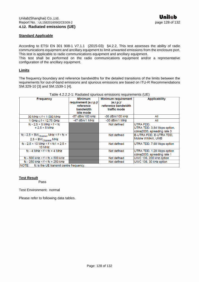
4.12. Radiated emissions (UE) Standard Applicable
According to ETSI EN 301 908-1 V7.1.1 (2015-03) §4.2.2, This test assesses the ability of radio communications equipment and ancillary equipment to limit unwanted emissions from the enclosure port. This test is applicable to radio communications equipment and ancillary equipment. This test shall be performed on the radio communications equipment and/or a representative configuration of the ancillary equipment. Limits The frequency boundary and reference bandwidths for the detailed transitions of the limits between the requirements for out-of-band emissions and spurious emissions are based on ITU-R Recommendations SM.329-10 [3] and SM.1539-1 [4].
Table 4.2.2.2-1: Radiated spurious emissions requirements (UE)
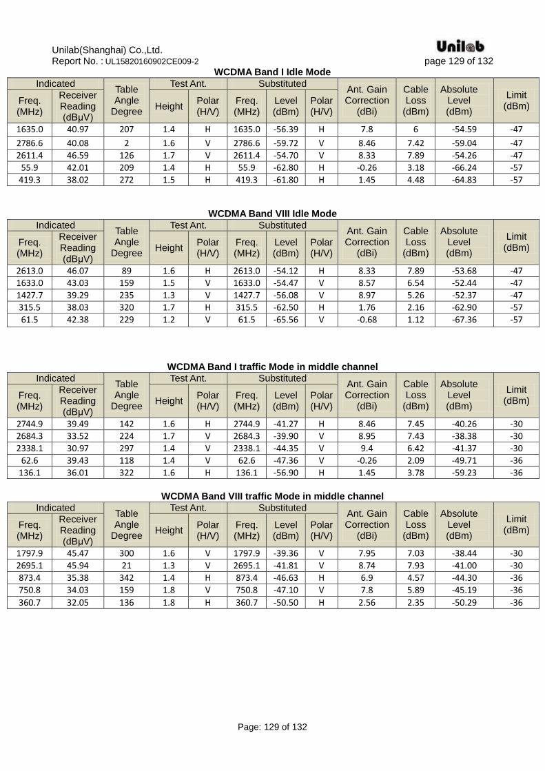
Test Result Pass Test Environment: normal Please refer to following data tables.
Unilab(Shanghai) Co.,Ltd. Report No. : UL15820160902CE009-2 page 129 of 132
Page: 129 of 132
WCDMA Band I Idle Mode
Indicated Table Angle
Degree
Test Ant. Substituted Ant. Gain Correction
(dBi)
Cable Loss
(dBm)
Absolute Level (dBm)
Limit (dBm)
Freq. (MHz)
Receiver Reading (dBμV)
Height Polar (H/V)
Freq. (MHz)
Level (dBm)
Polar (H/V)
1635.0 40.97 207 1.4 H 1635.0 -56.39 H 7.8 6 -54.59 -47
2786.6 40.08 2 1.6 V 2786.6 -59.72 V 8.46 7.42 -59.04 -47
2611.4 46.59 126 1.7 V 2611.4 -54.70 V 8.33 7.89 -54.26 -47
55.9 42.01 209 1.4 H 55.9 -62.80 H -0.26 3.18 -66.24 -57
419.3 38.02 272 1.5 H 419.3 -61.80 H 1.45 4.48 -64.83 -57
WCDMA Band VIII Idle Mode
Indicated Table Angle
Degree
Test Ant. Substituted Ant. Gain Correction
(dBi)
Cable Loss
(dBm)
Absolute Level (dBm)
Limit (dBm)
Freq. (MHz)
Receiver Reading (dBμV)
Height Polar (H/V)
Freq. (MHz)
Level (dBm)
Polar (H/V)
2613.0 46.07 89 1.6 H 2613.0 -54.12 H 8.33 7.89 -53.68 -47
1633.0 43.03 159 1.5 V 1633.0 -54.47 V 8.57 6.54 -52.44 -47
1427.7 39.29 235 1.3 V 1427.7 -56.08 V 8.97 5.26 -52.37 -47
315.5 38.03 320 1.7 H 315.5 -62.50 H 1.76 2.16 -62.90 -57
61.5 42.38 229 1.2 V 61.5 -65.56 V -0.68 1.12 -67.36 -57
WCDMA Band I traffic Mode in middle channel
Indicated Table Angle
Degree
Test Ant. Substituted Ant. Gain Correction
(dBi)
Cable Loss
(dBm)
Absolute Level (dBm)
Limit (dBm)
Freq. (MHz)
Receiver Reading (dBμV)
Height Polar (H/V)
Freq. (MHz)
Level (dBm)
Polar (H/V)
2744.9 39.49 142 1.6 H 2744.9 -41.27 H 8.46 7.45 -40.26 -30
2684.3 33.52 224 1.7 V 2684.3 -39.90 V 8.95 7.43 -38.38 -30
2338.1 30.97 297 1.4 V 2338.1 -44.35 V 9.4 6.42 -41.37 -30
62.6 39.43 118 1.4 V 62.6 -47.36 V -0.26 2.09 -49.71 -36
136.1 36.01 322 1.6 H 136.1 -56.90 H 1.45 3.78 -59.23 -36
WCDMA Band VIII traffic Mode in middle channel
Indicated Table Angle
Degree
Test Ant. Substituted Ant. Gain Correction
(dBi)
Cable Loss
(dBm)
Absolute Level (dBm)
Limit (dBm)
Freq. (MHz)
Receiver Reading (dBμV)
Height Polar (H/V)
Freq. (MHz)
Level (dBm)
Polar (H/V)
1797.9 45.47 300 1.6 V 1797.9 -39.36 V 7.95 7.03 -38.44 -30
2695.1 45.94 21 1.3 V 2695.1 -41.81 V 8.74 7.93 -41.00 -30
873.4 35.38 342 1.4 H 873.4 -46.63 H 6.9 4.57 -44.30 -36
750.8 34.03 159 1.8 V 750.8 -47.10 V 7.8 5.89 -45.19 -36
360.7 32.05 136 1.8 H 360.7 -50.50 H 2.56 2.35 -50.29 -36
Unilab(Shanghai) Co.,Ltd. Report No. : UL15820160902CE009-2 page 130 of 132
Page: 130 of 132
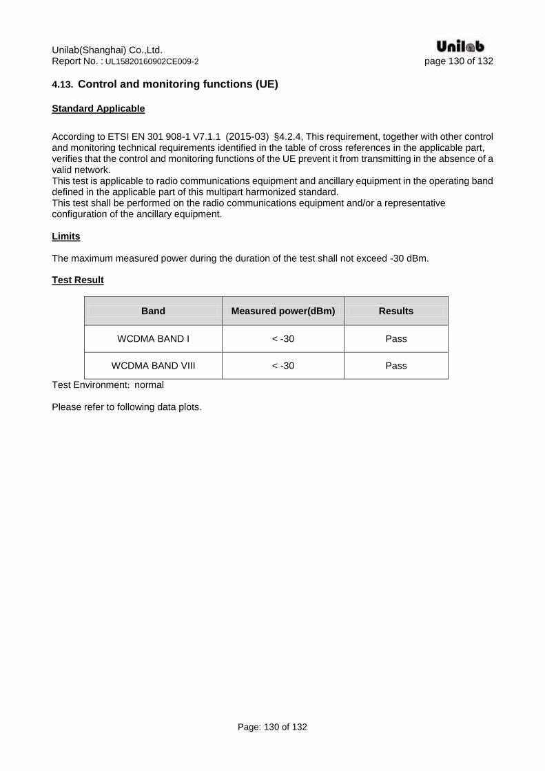
4.13. Control and monitoring functions (UE) Standard Applicable
According to ETSI EN 301 908-1 V7.1.1 (2015-03) §4.2.4, This requirement, together with other control and monitoring technical requirements identified in the table of cross references in the applicable part, verifies that the control and monitoring functions of the UE prevent it from transmitting in the absence of a valid network. This test is applicable to radio communications equipment and ancillary equipment in the operating band defined in the applicable part of this multipart harmonized standard. This test shall be performed on the radio communications equipment and/or a representative configuration of the ancillary equipment. Limits The maximum measured power during the duration of the test shall not exceed -30 dBm.
Test Result
Band Measured power(dBm) Results
WCDMA BAND I < -30 Pass
WCDMA BAND VIII < -30 Pass
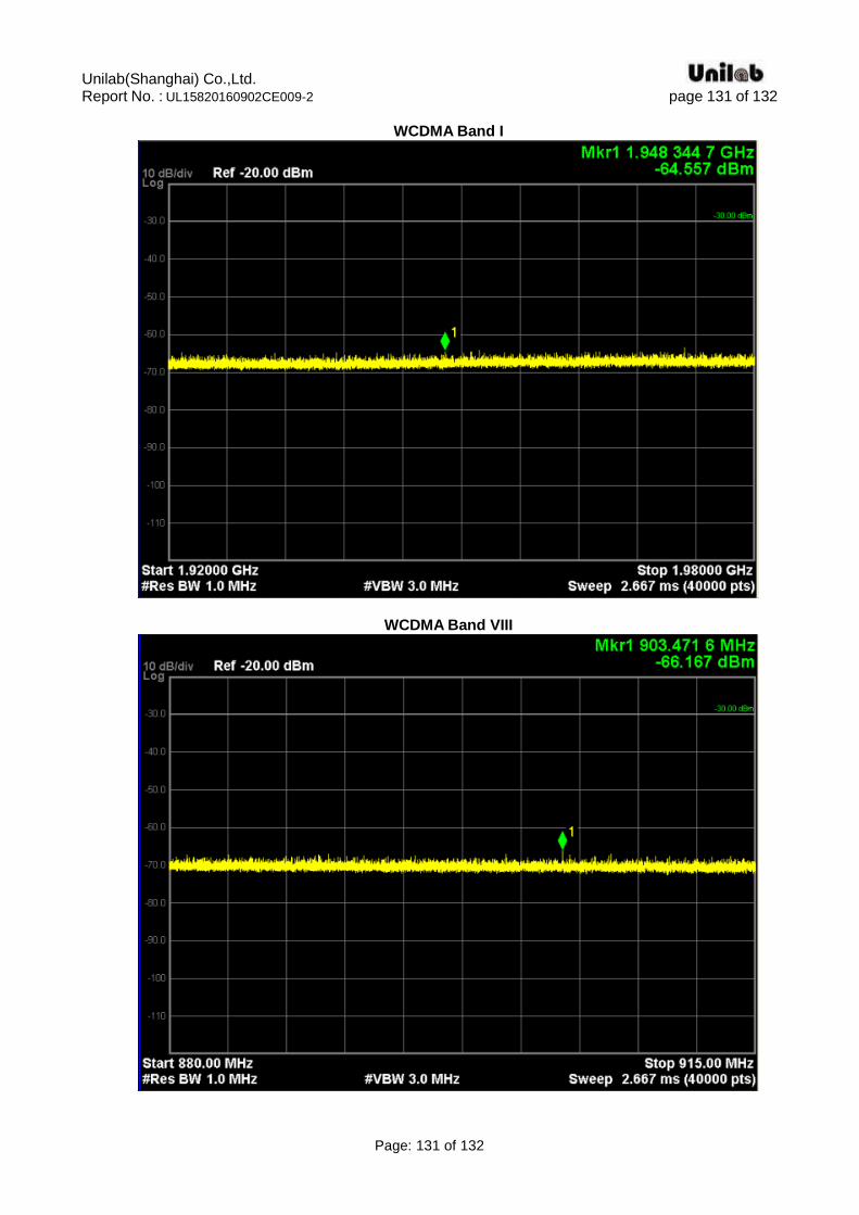
Test Environment: normal Please refer to following data plots.
Unilab(Shanghai) Co.,Ltd. Report No. : UL15820160902CE009-2 page 131 of 132
Page: 131 of 132
WCDMA Band I
WCDMA Band VIII
Unilab(Shanghai) Co.,Ltd. Report No. : UL15820160902CE009-2 page 132 of 132
Page: 132 of 132
APPENDIX 1 PHOTOGRAPHS OF TEST SETUP
Please refer to the file named “RF Test Setup Photos_SIM5300E”.
APPENDIX 2 PHOTOGRAPHS OF EUT
Please refer to the file named “EUT Photos_SIM5300E”.
----End of the report----