cea saclay experience
TRANSCRIPT

CEA Saclay Experience
Pierre Védrine, CEA Saclay, Irfu
EUCARD-2 WP3: Energy Efficiency
(EnEfficient)
Workshop on
Compact and Low Consumption Magnet Design
for Future Linear and Circular Colliders

INSTITUTE OF RESEARCH INTO THE FUNDAMENTAL
LAWS OF UNIVERSE
2
Irfu/SACM is developing and realizing particle accelerators, cryogenic systems and superconducting magnets for the scientific programs of Irfu and more widely of CEA.
Irfu/SACM is involved in large scale projects in Europe and in Japan.
Particle Physics
Nuclear Physics
Astrophysics
Space technologies
Accelerators,
Supra. Magnets
Systems engineering
Detectors, electronic,
computing
Institute of Research into the Fundamental laws of Universe

3
PAST EXPERIENCES
MAGNETS FOR PARTICLE PHYSICS
ATLAS Toroid magnet
CMS solenoid magnet
LHC quadrupole magnet

SUPERCONDUCTING MAGNETS
BACKGROUND
| PAGE 4
ATLAS and CMS: largest magnets Design and follow-up manufacturing
LARGE magnets Construction
For physics GLAD (GSI) For neuroscience ISEULT
Testing For fusion W7X & JT60SA
R&D Nb3Sn and HTS magnets Cryogenic systems Multi-scale simulations
LHC Upgrades Q4 NbTi Quadrupole for HL LHC 16 T Nb3Sn Dipole for FCC

5
(COMPACT AND LOW CONSUMPTION)
ATLAS EXPERIMENT

ATLAS IN COPPER CONDUCTOR !
Electrical Power > 100 MW
Winding size > 2-3 m
Weight > 5000 t of conductor
Reduced space for the detectors

MAGNET DESIGN FOR FUTURE PROJECTS
Efficient choice of conductor
Efficient magnet design
Efficient cryogeny for magnets
Save space for applications (detector, sample, …)
Reduce size, weight and cost …
Save helium, electrical consumption,
| PAGE 7
Magnets for HEP detectors High Field Magnets Cooling Schemes

FUTURE CIRCULAR COLLIDER-HH
LHC
27 km, 8.33 T
14 TeV (c.o.m.)
FCC-hh
80 km, 20 T 100 TeV (c.o.m.)
FCC-hh
100 km, 16 T 100 TeV (c.o.m.)
HE-LHC
27 km, 20 T 33 TeV (c.o.m.)
Geneva
PS
SPS
LHC

FCC / 100 TEV PROTON-PROTON DETECTOR MAGNET
100 TEV proton-proton collider needs a giant solenoid with followings design drivers
(extracted from H. ten Kate slides presented at FCC Workshop @ CERN, 27 May 2014)
26 NOVEMBRE 2014 | PAGE 9

FCC / 100 TEV PROTON-PROTON COLLIDER DETECTOR
A preliminary magnetic design has been performed at Saclay (G. Aubert) with
two driven hypothesis:
- Overall density to limit at 200MPa the hoop stress: ~7A/mm²
- Active shielding (120 000 t of iron required if passive shielding)
26 NOVEMBRE 2014 | PAGE 10
FCC Solenoid
22 GJ
24 m length
10 m diameter
CMS Solenoid
2.7 GJ
12.4 m length
6.6 m diameter

WHY NOT FCC DETECTOR MAGNET WITH MGB2?
In order to work at 10K
Today Jc MgB2 @10K/5T # 20 A/mm² but progress on-going
Jc in very large solenoid is limited by the stress (7A/mm² -> 200MPa)
| PAGE 11

WHY NOT FCC COLLIDER SOLENOID AT 10K?
To decrease the liquefier electrical power
From 4.2K to 10K, the efficiency increase is about 2.5 (Carnot based)
It could be possible to use the CMS liquefier (around 800 W at 4.45K & 4500 W at
50 K)
The actual CMS heat load at 4.4K is 200W
- 60% from radiative load
- 40% from supports load
Scaling assumption from CMS to FCC
- Radiative load is proportionnal to the surface
- Support load is proportionnal to the volume(=mass)
The FCC solenoid load at 4.4 K would be 1600W.
If a power equivalent to CMS refrigerator is « adapted » at 10K, the available power
could be about 2000W.

MGB2 R&D AT SACLAY: MULTIPURPOSE TEST FACILITY
13/32
Conduction cooled facility:
- Background field 3T (can be increased up to 5T)
- Temperature from 4K up to 40K
- Sample current up to 600A
- Sample diameter 300 mm
- Necessary for Wind&React MgB2 wire
13/21

MGB2 R&D AT SACLAY: PANCAKE WINDING
14/21
Double Pancake winding
DP impregnation
DP cross section
1 T / 2km wire solenoid under
manufacturing to be tested under 3T
background field

MGB2 R&D AT SACLAY: PARTNERSHIP AND PROJECTS
15/21
Industrial partnership:
- Winding technology development with SigmaPhi
- Wire material exchange agreement with Columbus
- Cryogen-free and MgB2 development support by Bpi France
Future:
- French ANR proposal “EcoChamp” for high field MgB2 solenoid
(LNCMI, SigamPhi, Columbus)
- FCC support for large MgB2 cable development ?

HIGH FIELD MAGNETS FOR RESEARCH
Magnetic fields serve as a powerful experimental probe
in physics, chemistry and in biology,
Numerous studies in physics, chemistry and biology require high
magnetic fields, homogeneous in space and stable in time.
Currently, magnetic fields above 23 T can only be generated by
resistive magnets, consisting of large water-cooled copper-based
coils in which large currents circulate.
Large electrical power consumption (typically 20 MW) and very
high operating costs, and only a few of such installations exist in the
world, giving access to all-resistive fields up to 38 T, and to hybrid
LTS-resistive fields up to 45 T.
This access is however very limited and very costly. 26 NOVEMBRE 2014 | PAGE 16

The 8.5 T Superconducting magnet
for the 43 T LNCMI hybride magnet.
Cryogenics design: Pressurized Superfluid Helium bath at 1.8 K &
1200 hPa
Goal: To offer a 43 Tesla static field platform
to the scientific community.
Superconduction coil Specifications:
Ri : 0.55 m - Re : 0.9 m - L : 1.4 m - W : 17 t
37 Double pancakes – 7100 A – 3 H – 76 MJ
Hybride Specifications:
43 T in 34 mm warm bore
Collaboration between CNRS and the CEA

34 TESLA RESISTIVE MAGNET
25 T 5 à 15 kA
400 V 2 x 6 MW
9 T 30 kA
400 V 12 MW
Bitter
PolyHelix

A ROBUST 8.5 TESLA SUPERCONDUCTING
MAGNET
8,5 T 7,1 kA 76 MJ
700 kW Liquefier and
pumps included
13 mm
18
mm
RUTHERFORD CABLE ON CONDUIT CONDUCTOR
The superfluid helium in the channel gives the
temperature margin for the coil. He II is 8 times more
energetics than cupper in the same volume.

A SUPERFLUID HELIUM INFRASTRUCTURE
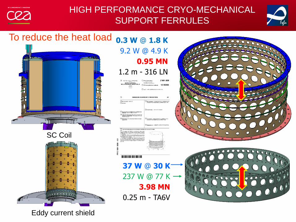
HIGH PERFORMANCE CRYO-MECHANICAL
SUPPORT FERRULES
0.3 W @ 1.8 K
9.2 W @ 4.9 K
0.95 MN
1.2 m - 316 LN
37 W @ 30 K
237 W @ 77 K
3.98 MN
0.25 m - TA6V
SC Coil
Eddy current shield
To reduce the heat load

HIGH FIELD
SUPRECONDUCTING MAGNET OPTION
| PAGE 22

ENVIRONMENTAL AND SOCIO-ECONOMIC IMPACT
By developing all-superconducting magnets for fields beyond 30 Tesla,
running costs would be considerably reduced,
with negligible electricity and moderate cooling costs.
This is a very important development for the financial sustainability of
the research in, and technical applications of, very high magnetic fields
in a context of rising electricity costs, particularly for high field NMR.
The operation of a resistive magnet demands the entire power of the
installation, and requires efficient cooling to remove this dissipated
energy.
The environmental impact is also to be taken into account when we
consider that currently only a minor fraction of this energy can be
recovered.

30T + FULLY SUPERCONDUCTING MAGNET
The aim of this project is to make a design of an
all-superconducting user magnet that will go significantly above
what is currently available, and to test critical components in a
prototype.
The design target chosen is a 30+ Tesla
(30 T minimum and more if possible) solenoid magnet.
A possible design that was suggested consists of a commercial
large-bore 19 T NbTi-Nb3Sn outer coil with an 11 T inner coil
made from HTS conductors, with an inner bore of 30 mm for sample.
| PAGE 24
TASUM H2020 Design study proposal

Helium entrance
Cryocooler
cold head
+
Condenser
Heat
exchanger
Fluid flow
34 cm
19,5 cm
COMPACT COOLING METHODS |
COUPLING TO CRYO-COOLER
Closed natural circulation loop
- Flow is created by the weight
unbalance between the two branches (density change)
- No pumps or pressurization system
- Vapor is re-condensed in the reservoir
Autonomous loop
- Auto-tuned mass flow rate (cooling)
- Independence from a refrigeration unit
Different temperature ranges
ThermAutonome project, CEA Saclay
– Perfect for 100 W compact class system located far from a refrigeration unit
Helium Ø4 mm circulation loop around 4.2 K h~5000 W/m2K
qc=500 W/m2
Y. Song et al., Nucleate boiling heat transfer in a helium natural circulation
loop coupled with a cryocooler, International Journal of Heat and Mass
Transfer, Volume 66, November 2013, Pages 64-71

COMPACT COOLING METHODS |
COUPLING TO CRYO-COOLER
• Pulsating heat pipe
– Pressure change due to volume expansion and contraction at
phase transition
– Oscillation of liquid slugs and vapor bubbles
– High heat transfer due to phase change and convection
– No gravity dependency
– Easy to implement (Any geometry possible)
– Autonomous thermal links
• Self sustained oscillations (cooling)
• Independence from a refrigeration unit
– Different temperature ranges
ThermAutonome project, CEA Saclay
PHP Adiabatic part
PHP Condenser
Cryocooler
170 W @ 77 K
PHP evaporator part
SR2S project, CEA Saclay
36 tubes PHP LN2 100 W class PHP
– Perfect for 100 W compact class system located far from a refrigeration unit without
any geometry dependency
K. Natsume, Heat transfer performance of cryogenic oscillating heat pipes for effective cooling of superconducting
magnets, Cryogenics, Volume 51, Issue 6, June 2011, Pages 309-314

SAVE THE ENERGY….
26 NOVEMBRE 2014 FAILURE (Pong ! ) or POWER (Bingo !)