ceiling fan instruction manual by pci not use water or detergents when cleaning the fan or fan...
TRANSCRIPT

Ceiling FanInstruction Manual
by PCI

Table of Contents
QUESTIONS, PROBLEMS, MISSING PARTS:Before returning to your local retailer, please call our Customer Service Team at 1-877-706-3267.
Safety Rules . . . . . . . . . . . . . . . . . . . 1
Unpacking Your Fan . . . . . . . . . . . . 2
Installing Your Fan . . . . . . . . . . . . . 3
Balancing Your Fan . . . . . . . . . . . 12
Operating Your Fan . . . . . . . . . . . 13
Care of Your Fan . . . . . . . . . . . . . 14
Troubleshooting . . . . . . . . . . . . . . 14
Specifications . . . . . . . . . . . . . . . . 15
Warranty Information . . . . . . . . . 16
Assistance Hotline . . . . . . . . . . . . 18
8002 ∙ 06/23/11 ∙ PCI
Another FineCeiling Fan
by PCI
Thank you for purchasing this PCI ceiling fan. This instruction manual will provide you with all the information to install and operate your new ceiling fan.
This product has been fabricated with the highest standards of quality and safety. Before Installing your new ceiling fan, for your records, remember to record your model number for warranty assistance. Please refer to page 16 (warranty) for further details.
! !WARNING
! !WARNING
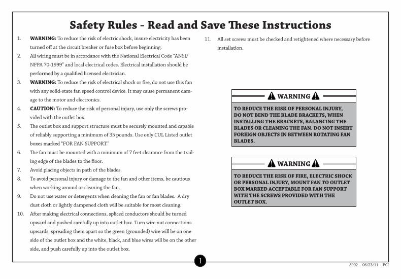
TO REDUCE THE RISK OF PERSONAL INJURY, DO NOT BEND THE BLADE BRACKETS, WHEN INSTALLING THE BRACKETS, BALANCING THE BLADES OR CLEANING THE FAN. DO NOT INSERT FOREIGN OBJECTS IN BETWEEN ROTATING FAN BLADES.
TO REDUCE THE RISK OF FIRE, ELECTRIC SHOCK OR PERSONAL INJURY, MOUNT FAN TO OUTLET BOX MARKED ACCEPTABLE FOR FAN SUPPORT WITH THE SCREWS PROVIDED WITH THE OUTLET BOX.
1
Safety Rules - Read and Save These Instructions1. WARNING: To reduce the risk of electric shock, insure electricity has been
turned off at the circuit breaker or fuse box before beginning.
2. All wiring must be in accordance with the National Electrical Code “ANSI/
NFPA 70-1999” and local electrical codes. Electrical installation should be
performed by a qualified licensed electrician.
3. WARNING: To reduce the risk of electrical shock or fire, do not use this fan
with any solid-state fan speed control device. It may cause permanent dam-
age to the motor and electronics.
4. CAUTION: To reduce the risk of personal injury, use only the screws pro-
vided with the outlet box.
5. The outlet box and support structure must be securely mounted and capable
of reliably supporting a minimum of 35 pounds. Use only CUL Listed outlet
boxes marked “FOR FAN SUPPORT.”
6. The fan must be mounted with a minimum of 7 feet clearance from the trail-
ing edge of the blades to the floor.
7. Avoid placing objects in path of the blades.
8. To avoid personal injury or damage to the fan and other items, be cautious
when working around or cleaning the fan.
9. Do not use water or detergents when cleaning the fan or fan blades. A dry
dust cloth or lightly dampened cloth will be suitable for most cleaning.
10. After making electrical connections, spliced conductors should be turned
upward and pushed carefully up into outlet box. Turn wire nut connections
upwards, spreading them apart so the green (grounded) wire will be on one
side of the outlet box and the white, black, and blue wires will be on the other
side, and push carefully up into the outlet box.
11. All set screws must be checked and retightened where necessary before
installation.
8002 ∙ 06/23/11 ∙ PCI

Standard Bowl EStar Bowl Globe Multi-Arm
The Fan you have purchased will be made up of one of the following light kit configurations:
Please follow the instructions as they pertain to your specific componets.
Standard BowlEstar Bowl
GlobeMulti-Arm
1
4
5
6
7
810
9
2
1
13 13
13
15
13
15
15 15
2
34
14 14
14 14
1617
18
11
! !WARNING
DO NOT INSTALL OR USE FAN IF ANY PART IS DAMAGED OR MISSING. CALL TOLL FREE 1-877-706-3267
2
Unpacking Your Fan
1. Set of blades (5)2. Balancing kit3. Blade Mounting
Hardware Kit (not shown)
Optional Remote Control16. Remote Transmitter17. Remote Receiver18. Remote Owner’s Manual
4. Owners Manual5. Blade Brackets (5) 6. Canopy / Bracket Assembly7. Ball / Downrod Assembly (4” and 12”)8. Pull Chain and Fob (2)9. Fan Motor Assembly10. Cap and Finials in all Finishes11. Switch Housing Cover12. Loose parts bags containing (not shown): Mounting hardware, blade attachment
hardware, electrical hardware, pull chains, wire connectors, etc.
13. Bowl14. Fitter15. 13W CFL Bulbs
(2)
13. EStar Bowl14. Fitter15. 13W GU24
CFL Bulbs (2)
13. Globe14. Fitter15. 13W CFL
Bulb
13. 3 or 4 Pieces of Side Glass
14. 13W CFL Bulbs (3 or 4)
15. Multi Arm Fitter
Replacement Parts
1. Blades (5)2. Blade Brackets (5)3. Hardware Kit4. Glass (3 Options)
8002 ∙ 06/23/11 ∙ PCI

Outlet Box
Outlet Box
Angled CeilingMaximum18° angle
Provide StrongSupport
HangerOpening MustBe Facing Up Side
Chip
RecessedOutlet Box
Outlet Box
! !WARNING
TO REDUCE THE RISK OF FIRE, ELECTRICSHOCK OR PERSONAL INJURY, MOUNT FANONLY TO AN OUTLET BOX MARKED ACCEPTABLE FOR FAN SUPPORT AND USE THE MOUNTING SCREWS PROVIDED WITH THE OUTLET BOX. OUTLET BOXES COMMONLY USED FOR THE SUPPORT OF LIGHTING FIXTURES MAY NOT BE ACCEPTABLE FOR FAN SUPPORT AND MAY NEED TO BE REPLACED. CONSULT A QUALIFIED ELECTRICIAN IF IN DOUBT.
3
Installing Your Fan
Tools Required
Mounting Options
Phillips screwdriver, adjustable wrench, stepladder, and wire cutters.
If there isn’t an existing mounting box, thenread the following instructions. Disconnect thepower by removing fuses or turning off circuitbreakers.
Secure the outlet box directly to the buildingstructure. Use appropriate fasteners and buildingmaterials. The outlet box and its supportmust be able to fully support the moving weightof the fan (at least 35 lbs.) Do not use plasticoutlet boxes.
Figures 1-3 are examples of different ways tomount the outlet box.
Note: You may need a longer downrod to maintain proper blade clearance when installing on asteep, sloped ceiling. The maximum angleallowable is 18°. If the canopy touches downrod, remove the decorative canopy bottom cover and turn the canopy 180° before attaching thecanopy to the mounting plate.
Note: For slope ceiling installation, make sure that the chip of the hanger bracket is toward the floor.
Figure 1
Figure 2
Figure 3
Figure 4
8002 ∙ 06/23/11 ∙ PCI
To hang your fan where there is an existing fixture but no ceiling joist, you may need an installation hanger bar as shown in Figure 4 (available at your PCI Retailer).
RemoveLoosen butDo Not Remove
UL ListedElectrical box
120VWires
HangerBracket
Mounting Screws(supplied withelectrical box)
Tab
Motor WiresBall / DownrodAssembly
Ceiling Canopy
Motor Collar Cap(Wet Fan Only)Motor Collar
Canopy BottomCover
4
Hanging Your Fan
Option 1:Standard Ceiling Mounting
Figure 5
Figure 6
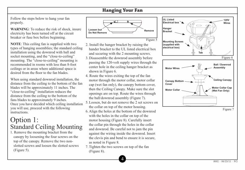
Follow the steps below to hang your fan properly.
WARNING: To reduce the risk of shock, insureelectricity has been turned off at the circuitbreaker or fuse box before beginning.
NOTE: This ceiling fan is supplied with twotypes of hanging assemblies; the standard ceilinginstallation using the downrod with ball andsocket mounting, and the “close-to-ceiling”mounting. The “close-to-ceiling” mounting isrecommended in rooms with less than 8-footceilings or in areas where additional space isdesired from the floor to the fan blades.
When using standard downrod installation, thedistance from the ceiling to the bottom of the fanblades will be approximately 11 inches. The“close-to-ceiling” installation reduces the distance from the ceiling to the bottom of the fans blades to approximately 9 inches.Once you have decided which ceiling installationyou will use, proceed with the following instructions.
1. Remove the mounting bracket from the canopy by loosening the four screws on the top of the canopy. Remove the two non-slotted screws and loosen the slotted screws (Figure 5).
2. Install the hanger bracket by raising the hander bracket to the UL listed electrical box and securing with the 2 mounting screws.
3. Disassemble the downrod assembly before passing the 120-volt supply wires through the center hole in the ceiling hanger bracket as shown in Figure 6.
4. Route the wires exiting the top of the fan motor through the motor collar, motor collar cap (wet fan only), the canopy bottom cover, then the Ceiling Canopy. Make sure the slot openings are on top. Route the wires through the ball/downrod assembly (Figure 7).
5. Loosen, but do not remove the 2 set screws on the collar on top of the motor housing.
6. Align the holes at the bottom of the downrod with the holes in the collar on top of the motor housing (Figure 8). Carefully insert the collar pin through the holes in the collar and downrod. Be careful not to jam the pin against the wiring inside the downrod. Insert the clevis pin and bend to ensure it is secure, as noted in Figure 8.
7. Tighten the two screws on top of the fan (Figure 8).
Figure 7
8002 ∙ 06/23/11 ∙ PCI
Screw and Lock washer
Gasket
Collar
Ceiling Canopy
RemoveLoosen butDo Not Remove
Canopy
ClevisPin
MotorHousing
Collar Pin
Set Screw
Canopy BottomCover
OutletBox
HangerBracket
Screws
Canopy
OutletBox
HangerBracket
Screws
! !WARNING
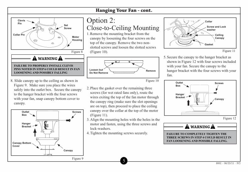
FAILURE TO COMPLETELY TIGHTEN THE THREE SCREWS IN STEP 4 COULD RESULT IN FAN LOOSENING AND POSSIBLE FALLING.
! !WARNING
FAILURE TO PROPERLY INSTALL CLEVIS PINS NOTED IN STEP 6 COULD RESULT IN FAN LOOSENING AND POSSIBLY FALLING
5
Hanging Your Fan - cont.
Option 2:Close-to-Ceiling Mounting
Figure 10
1. Remove the mounting bracket from the canopy by loosening the four screws on the top of the canopy. Remove the two non-slotted screws and loosen the slotted screws (Figure 10).
5. Secure the canopy to the hanger bracket as shown in Figure 12 with four screws included with your fan. Secure the canopy to the hanger bracket with the four screws with your fan.
2. Place the gasket over the remaining three screws (for wet rated fans only), route the wires exiting the top of the fan motor through the canopy ring (make sure the slot openings are on top), then proceed to place the ceiling canopy over the collar at the top of the motor (Figure 11).
3. Align the mounting holes with the holes in the motor and fasten, using the three screws and lock-washers.
4. Tighten the mounting screws securely.
Figure 11
Figure 9
Figure 8
8. Slide canopy up to the ceiling as shown in Figure 9. Make sure you place the wires safely into the outlet box. Secure the canopy to the hanger bracket with the four screws with your fan, snap canopy bottom cover to canopy.
Figure 12
8002 ∙ 06/23/11 ∙ PCI

TRIC
RKED
ULListedElectricalBox
SlideMountingBracketOverScrew Heads
CeilingMountingBracket
Hook
120VWires
MountingScrews(Supplied withElectrical Box)
Close-to-CeilingMounting
Standard Mounting
! !WARNING
! !WARNING
! !WARNING
! !WARNING
WHEN MOUNTING THE FAN ON A SLOPEDCEILING, THE STANDARD BALL/DOWNRODMOUNTING METHOD MUST BE USED. MAKESURE THE MOUNTING PLATE SLOTS ARE ONTHE LOWER SIDE BY SLIDING THE MOUNTINGBRACKET FROM THE TOP DOWN.
TO REDUCE THE RISK OF FIRE, ELECTRICSHOCK OR OTHER PERSONAL INJURY, MOUNTFAN ONLY TO AN OUTLET BOX MARKEDACCEPTABLE FOR FAN SUPPORT AND USE THEMOUNTING SCREWS PROVIDED WITH THEOUTLET BOX.
WHEN USING THE STANDARD BALL/DOWNRODMOUNTING. THE TAB IN THE RING MUST RESTIN THE GROOVE OF THE HANGER BALL. FAILURE TO PROPERLY SEAT THE TAB IN THEGROOVE COULD CAUSE DAMAGE TO WIRING.
THE HOOK AS SHOWN IN FIGURE 11 IS ONLY TOBALANCE THE FAN WHILE ATTACHINGWIRING. FAILURE TO HANG AS SHOWN IN FIGURE 14 MAY RESULT IN HOOK BREAKINGCAUSING THE FAN TO FALL. HOOK MUST PASSFROM INSIDE TO OUTSIDE OF CANOPY.
6
Installing Your Fan To The Electrical Box
Figure 13 Figure 14
1. Pass the 120-volt supply wires through the center hole in the ceiling mounting plate as shown in Figure 13.
2. Install the ceiling mounting bracket on the outlet box, by sliding the mounting plate over the two screws provided with the outlet box (Figure 13). When using “close-to-ceiling” mounting, it is important that the mounting bracket be level. If necessary, use leveling washers (not included) between the mounting bracket and the electrical box.
Note that the flat side of the mounting bracket is toward the electrical box (Figure 13).
3. Securely tighten the two mounting screws.
4. If using the “close-to-ceiling” mounting option, carefully lift the fan assembly up to the ceiling mounting bracket and hang the fan on the hook provided by utilizing one of the holes at the outer rim of the ceiling canopy (Figure 14). If Using standard mounting, seat the hanger ball in the mounting bracket socket. Make sure the tab on the mounting bracket socket is properly seated in the groove in the hanger ball (Figure 14).
8002 ∙ 06/23/11 ∙ PCI
SUPPLY CIRCUIT
BLA
CK
WH
ITE
BLA
CK
BLU
E
GR
EEN
WH
ITE
GroundConductor
Outlet Box
GreenGroundLead
Ground toDownrodSwitch
Canopy
Motor Housing
! !WARNING
! !WARNING
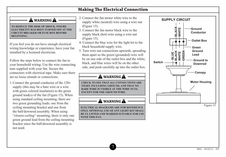
ELECTRICAL DIAGRAMS ARE FOR REFERENCEONLY. OPTIONAL USE OF ANY LIGHT KIT SHALL BE UL LISTED AND MARKED SUITABLE FOR USE WITH THIS FAN.
CHECK TO SEE THAT ALL CONNECTIONS ARETIGHT, INCLUDING GROUND, AND THAT NOBARE WIRE IS VISIBLE AT THE WIRE NUTS,EXCEPT FOR THE GROUND WIRE.
! !WARNINGTO REDUCE THE RISK OF SHOCK, INSURE ELECTRICITY HAS BEEN TURNED OFF AT THE CIRCUIT BREAKER OR FUSE BOX BEFORE BEGINNING.
7
Making The Electrical Connection
Figure 15
If you feel you do not have enough electricalwiring knowledge or experience, have your faninstalled by a licensed electrician.
Follow the steps below to connect the fan toyour household wiring. Use the wire connectingnuts supplied with your fan. Secure the connectors with electrical tape. Make sure there are no loose strands or connections.
1. Connect the ground conductor of the 120v supply (this may be a bare wire or a wire with green colored insulation) to the green ground lead(s) of the fan (Figure 15). When using standard ceiling mounting, there are two green grounding leads; one from the ceiling mounting bracket and one from the ball/downrod assembly. When using “closeto-ceiling” mounting, there is only one green ground lead from the ceiling mounting bracket since the ball/downrod assembly is not used.
2. Connect the fan motor white wire to the supply white (neutral) wire using a wire nut (Figure 15).
3. Connect the fan motor black wire to the supply black (hot) wire using a wire nut (Figure 15).
4. Connect the blue wire for the light kit to the black household supply wire.
5. Turn wire nut connections upwards, spreading them apart so the green (grounded) wire will be on one side of the outlet box and the white, black, and blue wires will be on the other side, and push carefully up into the outlet box.
8002 ∙ 06/23/11 ∙ PCI

Screws
Blade Bracket
Blade Bracket
Screw
Paper Washer
Blade
Washers
! !WARNING
! !WARNING
MOTOR IS SHIPPED WITH RUBBER MOTORBLOCKS TO PREVENT MOVEMENT DURINGTRANSPORTATION. REMOVE MOTOR BLOCKS PRIOR TO ATTACHING BLADE BRACKETS.
LOCKING SLOTS OF CEILING CANOPY ARE AN AID TO MOUNTING, DO NOT LEAVE FAN ASSEMBLY UNATTENDED UNTIL ALL FOUR CANOPY SCREWS ARE ENGAGED AND FIRMLY TIGHTENED.
8
Finishing The Fan Installation
Figure 16
Figure 17
Attaching the Fan Blades
2. Tighten each screw securely.3. Fasten the blade assembly to the motor by
inserting the alignment post into the slot on the bottom of the motor and tightening the motor screws. Please note that the motor screws may be pre-attached into the blade brackets (Figure 17).
4. Repeat steps 1-3 for the remaining blades.
1. Attach blade to blade bracket using the screws provided (Figure 16). Insert a screw into the bracket. Repeat for the two remaining screws.
1. Align the locking slots of the ceiling canopy with the two screws in the mounting plate. Push up to engage the slots and turn clockwise to lock in place. Immediately tighten the two mounting screws firmly.
2. Install the remaining two mounting screws into the holes in the canopy and tighten firmly.
3. You may now proceed to attaching the fan blades.
1. Carefully unhook the fan from the mounting plate and align the locking slots of the canopy with the two screws in the mounting plate. Push up to engage slots and turn clockwise to lock in place. Immediately tighten the two mounting screws firmly.
2. Install the remaining two mounting screws into the holes in the canopy and tighten firmly.
3. You may now proceed to attaching the fan blades.
Close-to-Ceiling Mounting
Standard Ceiling Mounting
8002 ∙ 06/23/11 ∙ PCI

Switch HousingScrews
Thumbscrews
Blue Wires
White Wires
Bulb
Light Kit
Globe
Fan with light kit
9
Glass Installation Options 1
Figure 18
Figure 19
1. Connect the two blue to blue light kit wires by single pin and connect the two white to white light kit wires by single pin.
2. Remove the three screws from the switch housing, then insert the light kit into the switch housing.
3. Align the three screw holes in the switch housing with the screw holes in the light kit.
4. Re-Install the three screws.
1. Only the fan pull chain is functional. Second light pull chain in switch housing does not function for this configuration but must be in the “on” position for proper light kit operation.
2. Refer to the instructions that came with your accessory light kit for proper assembly.
3. Consult a certified electrician if needed.
5. Install bulb provided.6. Insert the globe into the fixture. Tighten the
thumbscrews manually until finger-tight. Do not overtighten.
Note: If thumbscrews are pre-installed, loosen the thumbscrews before inserting the globe, then retighten securely.
Your Fan will have one of the following 3 light kit options: Globe, Bowl, or Multi-Arm Light Kit.
Option 1Attaching the Globe
Aftermarket OptionAccessory Light Kitfor fans without light kits
8002 ∙ 06/23/11 ∙ PCI
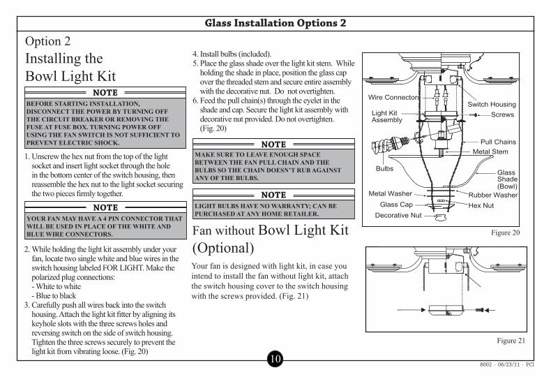
Screws
Pull Chains
Switch Housing
Bulbs Glass Shade(Bowl)
Glass CapDecorative Nut
Metal Washer Rubber WasherHex Nut
Wire Connectors
Light KitAssembly
Metal Stem
Switch Housing
ScrewsSwitch HousingCover
NOTE
NOTE
BEFORE STARTING INSTALLATION, DISCONNECT THE POWER BY TURNING OFF THE CIRCUIT BREAKER OR REMOVING THE FUSE AT FUSE BOX. TURNING POWER OFF USING THE FAN SWITCH IS NOT SUFFICIENT TO PREVENT ELECTRIC SHOCK.
MAKE SURE TO LEAVE ENOUGH SPACEBETWEEN THE FAN PULL CHAIN AND THEBULBS SO THE CHAIN DOESN’T RUB AGAINSTANY OF THE BULBS.
NOTELIGHT BULBS HAVE NO WARRANTY; CAN BEPURCHASED AT ANY HOME RETAILER.
NOTEYOUR FAN MAY HAVE A 4 PIN CONNECTOR THAT WILL BE USED IN PLACE OF THE WHITE AND BLUE WIRE CONNECTORS.
10
Glass Installation Options 2
Option 2Installing the Bowl Light Kit
1. Unscrew the hex nut from the top of the light socket and insert light socket through the hole in the bottom center of the switch housing, then reassemble the hex nut to the light socket securing the two pieces firmly together.
2. While holding the light kit assembly under your fan, locate two single white and blue wires in the switch housing labeled FOR LIGHT. Make the polarized plug connections:
- White to white - Blue to black 3. Carefully push all wires back into the switch
housing. Attach the light kit fitter by aligning its keyhole slots with the three screws holes and reversing switch on the side of switch housing. Tighten the three screws securely to prevent the light kit from vibrating loose. (Fig. 20)
Your fan is designed with light kit, in case youintend to install the fan without light kit, attach the switch housing cover to the switch housing with the screws provided. (Fig. 21)
Fan without Bowl Light Kit (Optional)
4. Install bulbs (included).5. Place the glass shade over the light kit stem. While
holding the shade in place, position the glass cap over the threaded stem and secure entire assembly with the decorative nut. Do not overtighten.
6. Feed the pull chain(s) through the eyelet in the shade and cap. Secure the light kit assembly with decorative nut provided. Do not overtighten.
(Fig. 20)
Figure 20
Figure 21
8002 ∙ 06/23/11 ∙ PCI

Screws
Light kit
ReverseSwitch
4 Pin Connector(or 4 pin connector)
Switch Housing
Thumb Screws
Bulbs
Glass Shade
NOTEYOUR FAN MAY HAVE A 4 PIN CONNECTOR THAT WILL BE USED IN PLACE OF THE WHITE AND BLUE WIRE CONNECTORS
! !CAUTIONBEFORE STARTING INSTALLATION, DISCONNECT THE POWER BY TURNING OFF THE CIRCUIT BREAKER OR REMOVING THE FUSE AT FUSE BOX. TURNING POWER OFF USING THE FAN SWITCH IS NOT SUFFICIENT TOPREVENT ELECTRIC SHOCK.
NOTETHE LIGHT KIT WITH YOUR FAN MAY HAVE 3 OR 4 LIGHTS
11
Glass Installation Options 3
Figure 22
Figure 23
Option 3Installing the Multi Arm Light Kit
1. While holding the light kit assembly under your fan, locate two single white and blue wires in the switch housing labeled FOR LIGHT. Make the polarized plug connections:
- White to white - Blue to black
2. Carefully push all wires back into the switch housing. Attach the light kit fitter by aligning its keyhole slots with the three screw holes and the reverse switch on the side of the switch housing. Tighten the three screws securely to prevent the light kit from vibrating loose. (Fig. 22)
3. Mount the glass shades to the light fixture by unscrewing partway the thumbscrews on the glass holders, insert the glass, then gently tighten the thumbscrews by hand evenly to the glass. DO NOT OVER TIGHTEN
(Fig. 23).4. Install three bulbs (included). NOTE: CFL
bulbs are NOT dimmable.
8002 ∙ 06/23/11 ∙ PCI

TouchingCeiling
AdhesiveWeight
Blade Clip-On Weight
12
Balancing Your Fan
Figure 24
The following procedure should correct most fan wobble.Check after each step.1. Check that all blade and blade bracket screws are secure.2. Most fan wobble problems are caused when blade levels are unequal. Check this level
by selecting a point on the ceiling above the tip of one of the blades. Measure from a point on the tip of each blade to a point directly above the blade on the ceiling. Measure this distance as shown in Figure 24. Rotate the fan until the next blade is positioned for measurement. Repeat for each blade. Measurements deviation should be within 1/8”. Run the fan for 10 Minutes.
3. Use the enclosed Blade Balancing Kit if the blade wobble is still noticeable.4. To use the kit, begin by adjusting the fan speed to find where you get the most wobble.5. Turn off the fan and then attach the clip-on weight about halfway down any blade. 6. Turn the fan back on to see if this has helped the wobble, continue moving the clip-on
weight from blade to blade.7. Once you have isolated the “wobble” blade, start moving the clip-on weight up and down
the length of the blade (starting and stopping the fan each time) until you locate the correct spot to stop the wobble.
8. Once the wobble has been located, place one of the adhesive weight on the upper side of the blade where the clip-on weight was located.
9. Remove the clip-on weight, turn the fan on.
Figure 25
8002 ∙ 06/23/11 ∙ PCI

NOTEWAIT FOR FAN TO STOP BEFORE CHANGING THE SETTING OF THE SLIDE SWITCH.
13
Operating Your Fan
Turn on the power and check the operation of your fan. There are two pull chains available in your fan:
1. 3-speed pull chain- it controls the fan speed as follows:1-Pull = High Speed2-Pulls = Medium Speed3-Pulls = Low Speed4-Pulls = Fan Off
Speed settings for warm or cool weather depend on factors such as the room size, ceiling height, number of fans, and so on.
Cool weather - (Reverse) An upward airflow moves warm air off the ceiling area as shown in Figure 27. This allows you to set your heating unit on a lower setting without affecting your comfort.
The slide switch controls directions: forward (switch down ) or reverse (switch up ).
Warm weather - (Forward) A downward air flow creates a cooling effect as shown in Figure 26. This allows you to set your air conditioner on a higher setting without affecting your comfort.
Figure 26 Figure 27
8002 ∙ 06/23/11 ∙ PCI

! !WARNINGMAKE SURE THE POWER IS OFF AT THE ELECTRICAL PANEL BOX BEFORE YOU ATTEMPT ANY REPAIRS. REFER TO THE SECTION, “MAKING ELECTRICAL CONNECTIONS.”
14
Care Of Your Fan / Troubleshooting
Care of Your Fan TroubleshootingPROBLEM SOLUTIONHere are some suggestions to help you
maintain your fan.1. Because of the fan’s natural movement,
some connections may become loose. Check the support connections, brackets, and blade attachments twice a year. Make sure they are secure. (It is not necessary to remove fan from ceiling.)
2. Clean your fan periodically to help maintain its new appearance over the years. Do not use water when cleaning. Use only a soft brush or lint-free cloth to avoid scratching the finish. The plating is sealed with a lacquer to minimize discoloration or tarnishing.
3. You can apply a light coat of furniture polish to the wood for additional protection and enhanced beauty. Cover small scratches with a light application of shoe polish.
4. There is no need to oil your fan. The motor has permanently lubricated sealed ball bearings.
1. Check main and branch circuit fuses or breakers.2. Check line wire connections to the fan and switch wire
connections in the switch housing.
1. Make sure all motor housing screws are snug.2. Make sure the screws that attach the fan blades bracket to the
motor hub are tight.3. Make sure wire nut connections are not rattling against each
other or the interior wall of the switch housing. CAUTION: Make sure main power is off.4. Allow a 24-hour “breaking-in” period. Most noises associated
with a new fan disappear during this time.5. If using the ceiling fan light kit, make sure the screws securing
the glassware are tight. Check that the light bulb is also secure.6. Make sure there is a short distance from the ceiling to the
canopy. It should not touch the ceiling.7. Make sure your ceiling box is secure and rubber isolator pads
are used between mounting bracket and outlet box.
Fan will not start
Fan sounds noisy
8002 ∙ 06/23/11 ∙ PCI

Typical Measurements for This Fan Series.
NOTETHE VALUES ON THIS CHART ARE APPROXIMATE AND REPRESENTATIVE OF THE PERFORMANCE OF TYPICAL FANS WITH THE SAME SIZE MOTOR, BLADE DIAMETERS AND PITCH AS THE FAN YOU PURCHASED. THESE MEASUREMENTS DO NOT INCLUDE ANY POWER THAT THE LIGHT KIT USES. FOR PRECISE SPECIFICATIONS PLEASE REFER TO THE CHART ON THE CARTON.
15
Specifications
These are approximate measures. They do not include Amps and Wattage used by the light kit.
Fan Size Speed Volts Amps Watts RPM CFM CFM/W
52”(1.32 m)
Low 120 0.21 9.9 56 1644 166
Medium 120 0.34 26.5 101 3090 117
High 120 0.50 59.9 146 4569 76
8002 ∙ 06/23/11 ∙ PCI

16
Warranty
IMPORTANT NOTE:To ensure warranty service, your fan must be
registered (see warranty card herein)
You must present a copy of the originalpurchase receipt to obtain warranty service.
CEILING FAN WARRANTY CENTER3059 FOREST HILL IRENE RD., SUITE 103
GERMANTOWN, TN 38138
Attach receipt here foreasy location.
8002 ∙ 06/23/11 ∙ PCI
PCI Lifetime Limited Warranty(Lifetime warranty on motor)PCI warrants the fan motor to be free from defects in workmanship and material present at time of shipment from the factory for a lifetime after the date of purchase by the original purchaser. PCI also warrants that all other fan parts, excluding any glass or acrylic blades, to be free from defects in workmanship and material at the time of shipment from the factory for a period of one years after the date of purchase by the original purchaser. We agree to correct such defects without charge or at our option replace with a comparable or superior model if the product is returned to PCI. To obtain warranty service, you must present a copy of the receipt as proof of purchase. All costs of removing and reinstalling the product are your responsibility. Damage to any part such as by accident or misuse or improper installation or by affixing any accessories, is not covered by this warranty. Because of varying climatic conditions, this warranty does not cover any changes in plated finishes, including rusting, pitting, corroding, tarnishing or peeling. Brass finishes of this type give their longest useful life when protected from varying weather conditions. A certain amount of “wobble” is normal and should not be considered a defect. Servicing performed by unauthorized persons shall render the warranty invalid. To obtain service, contact our service department at 1-877-706-3267. You will be responsible for all insurance and freight charges. A copy of the sales receipt is required to obtain service. We will return you fan freight pre-paid. Please pack your fan properly to avoid damage in transit. PCI will not be responsible for such damages.
In no event shall PCI be liable for consequential or incidental damages.
Some states do not allow the exclusion or limitation of consequential or incidental damages, in which case the above limitation or exclusion may not apply.
This warranty gives you specific legal rights. You may also have other rights which vary state to state.

17
Owner Registration Card
8002 ∙ 06/23/11 ∙ PCI
Ow
ner R
egis
trat
ion
Car
dPl
ease
fill
out,
cut a
long
das
hed
line,
affi
x pr
oper
pos
tage
and
retu
rn th
e ow
ner
regi
stra
tion
card
with
in 1
0 da
ys to
insu
re th
at y
our n
ew C
eilin
g Fa
n is
cov
ered
by
the
limite
d w
arra
nty.
Purc
hase
r’s N
ame:
Addr
ess:
Stat
e:
Z
ip:
Mod
el N
o:
P
urch
ase
Dat
e:
Whe
re P
urch
ased
(Sto
re N
ame)
:
Stor
e Ad
dres
s:
Sta
te:
Zi
p:
Type
of s
tore
whe
re p
urch
ased
:
If ho
me
inst
alla
tion,
whi
ch ro
om?
Whe
re fa
n w
ill b
e us
ed:
If co
mm
erci
al In
stitu
tion,
wha
t typ
e of
bus
ines
s?
Ligh
ting
Cen
ter
Bui
ldin
g Su
pply
Cen
ter
Dep
artm
ent S
tore
Fam
ily R
oom
Pa
tio
Livi
ng R
oom
Rest
aura
nt
B
ar
Stor
e
Office
Oth
er
Bedr
oom
P
orch
Kitc
hen
Oth
er
Oth
er
Vend
or N
o:
UPC
:
18
Assistance Hotline
8002 ∙ 06/23/11 ∙ PCI
CALL TOLL-FREEFOR ASSISTANCE
WE PROVIDEPrompt shipment of missing, broken, or defective parts. CALL 1-877-706-3267 Between 8:00 am and 5:00 pm PacificStandardTime,Monday-Friday
Glass BrokenMissing Parts?
?
NEED HELP?PleaseDONOTRETURNMERCHANDISE
BEFOREYOUCALL