cell phone lockers - 19000 · pdf filesalsbury industries 1010 east 62nd street, los angeles,...
TRANSCRIPT

SALSBURY INDUSTRIES 1010 East 62
nd Street, Los Angeles, CA 90001-1598
Phone: 1-800-624-5269 Int’l Phone: 323-846-6700 Fax: 1-800-624-5299 Int’l Fax: 323-846-6800
www.lockers.com www.mailboxes.com [email protected] [email protected]
Installation instructions are provided as general guidelines. It is advised that a professional installer be consulted. Salsbury Industries assumes no product assembly or installation liability. Copyright © 2014 Salsbury Industries. All rights reserved. (Rev. 12, 1/21/2014) Page 1 of 10
Cell Phone Lockers - 19000 Series Surface Mounted Installation Instructions
Installation of the Surface Mounted Enclosure Remove the locker unit from the enclosure. Drill mounting holes in the enclosure to fasten it to the mounting surface. It is important to use at least four (4) fasteners (not provided) and place one each at the four (4) corners of the mounting surface (either on the rear panel or the bottom panel). Choose appropriate hardware for the particular conditions of the installation.
Installing the Cell Phone Locker into the Enclosure Install the locker unit into the enclosure by sliding it into the enclosure until its front peripheral flange is flush against the front of the enclosure. Open the four corner compartments of the cell phone locker. Install #8 x 1-1/4 in. long screws (provided) through the top and bottom of the locker unit into the enclosure. Close the compartment doors.

SALSBURY INDUSTRIES 1010 East 62
nd Street, Los Angeles, CA 90001-1598
Phone: 1-800-624-5269 Int’l Phone: 323-846-6700 Fax: 1-800-624-5299 Int’l Fax: 323-846-6800
www.lockers.com www.mailboxes.com [email protected] [email protected]
Installation instructions are provided as general guidelines. It is advised that a professional installer be consulted. Salsbury Industries assumes no product assembly or installation liability. Copyright © 2014 Salsbury Industries. All rights reserved. (Rev. 12, 1/21/2014) Page 2 of 10
Cell Phone Lockers - 19100 Series Surface Mounted with Front Access Panel
Installation Instructions
Installation of the Surface Mounted Enclosure Remove the locker unit from the enclosure. Drill mounting holes in the enclosure to fasten it to the mounting surface. It is important to use at least four (4) fasteners (not provided) and place one each at the four (4) corners of the mounting surface (either on the rear panel or the bottom panel). Choose appropriate hardware for the particular conditions of the installation.
Installing the Cell Phone Locker into the Enclosure Install the locker unit into the enclosure by sliding it into the enclosure until its front peripheral flange is flush against the front of the enclosure. Open the front panel access compartment of the cell phone locker then open the front panel. Install #8 x 3/4 in. long screws (provided) through the slots in the sides of the front peripheral flange of the locker unit into the enclosure. Close the front panel then the front panel access compartment.
SALSBURY INDUSTRIES 1010 East 62
nd Street, Los Angeles, CA 90001-1598
Phone: 1-800-624-5269 Int’l Phone: 323-846-6700 Fax: 1-800-624-5299 Int’l Fax: 323-846-6800
www.lockers.com www.mailboxes.com [email protected] [email protected]
Installation instructions are provided as general guidelines. It is advised that a professional installer be consulted. Salsbury Industries assumes no product assembly or installation liability. Copyright © 2014 Salsbury Industries. All rights reserved. (Rev. 12, 1/21/2014) Page 3 of 10
Cell Phone Lockers – 19000/19100 Series Surface Mounted Installation Instructions
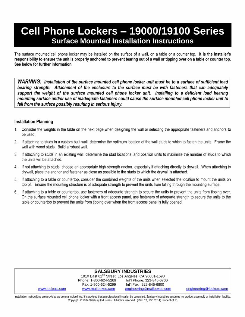
The surface mounted cell phone locker may be installed on the surface of a wall, on a table or a counter top. It is the installer’s responsibility to ensure the unit is properly anchored to prevent tearing out of a wall or tipping over on a table or counter top. See below for further information.
WARNING: Installation of the surface mounted cell phone locker unit must be to a surface of sufficient load
bearing strength. Attachment of the enclosure to the surface must be with fasteners that can adequately support the weight of the surface mounted cell phone locker unit. Installing to a deficient load bearing mounting surface and/or use of inadequate fasteners could cause the surface mounted cell phone locker unit to fall from the surface possibly resulting in serious injury.
Installation Planning
1. Consider the weights in the table on the next page when designing the wall or selecting the appropriate fasteners and anchors to be used.
2. If attaching to studs in a custom built wall, determine the optimum location of the wall studs to which to fasten the units. Frame the wall with wood studs. Build a robust wall.
3. If attaching to studs in an existing wall, determine the stud locations, and position units to maximize the number of studs to which the units will be attached.
4. If not attaching to studs, choose an appropriate high strength anchor, especially if attaching directly to drywall. When attaching to drywall, place the anchor and fastener as close as possible to the studs to which the drywall is attached.
5. If attaching to a table or countertop, consider the combined weights of the units when selected the location to mount the units on top of. Ensure the mounting structure is of adequate strength to prevent the units from falling through the mounting surface.
6. If attaching to a table or countertop, use fasteners of adequate strength to secure the units to prevent the units from tipping over. On the surface mounted cell phone locker with a front access panel, use fasteners of adequate strength to secure the units to the table or countertop to prevent the units from tipping over when the front access panel is fully opened.

SALSBURY INDUSTRIES 1010 East 62
nd Street, Los Angeles, CA 90001-1598
Phone: 1-800-624-5269 Int’l Phone: 323-846-6700 Fax: 1-800-624-5299 Int’l Fax: 323-846-6800
www.lockers.com www.mailboxes.com [email protected] [email protected]
Installation instructions are provided as general guidelines. It is advised that a professional installer be consulted. Salsbury Industries assumes no product assembly or installation liability. Copyright © 2014 Salsbury Industries. All rights reserved. (Rev. 12, 1/21/2014) Page 4 of 10
Cell Phone Lockers – 19000/19100 Series Surface Mounted Installation
Weights of Surface Mounted Cell Phone Lockers
8” Deep Compartments
7 Doors High Total Weight – Lbs.
19078/19178-14 2 “A” Doors Wide 95
19078/19178-21 3 “A” Doors Wide 155
19078/19178-24 4 “A” Doors Wide 175
19078/19178-35 5 “A” Doors Wide 250
6 Doors High
19068/19168-10 2 “A” Doors Wide 80
19068/19168-18 3 “A” Doors Wide 130
19068/19168-20 4 “A” Doors Wide 170
19068/19168-30 5 “A” Doors Wide 215
5 Doors High
19058/19158-09 2 “A” Doors Wide 65
19058/19158-10 2 “B” Doors Wide 125
19058/19158-15 3 “A” Doors Wide 100
19058/19158-16 4 “A” Doors Wide 130
19058/19158-20 4 “A” Doors Wide 135
19058/19158-25 5 “A” Doors Wide 180
4 Doors High
19048/19148-07 2 “A” Doors Wide 55
19048/19148-12 3 “A” Doors Wide 90
19048/19148-14 4 “A” Doors Wide 115
19048/19148-20 5 “A” Doors Wide 145
3 Doors High
19038/19138-06 2 “A” Doors Wide 45
19038/19138-09 3 “A” Doors Wide 65
19038/19138-10 4 “A” Doors Wide 90
19038/19138-15 5 “A” Doors Wide 110
5” Deep Compartments
7 Doors High Total Weight – Lbs.
19075/19175-14 2 “A” Doors Wide 90
19075/19175-21 3 “A” Doors Wide 145
19075/19175-24 4 “A” Doors Wide 165
19075/19175-35 5 “A” Doors Wide 235
6 Doors High
19065/19165-10 2 “A” Doors Wide 75
19065/19165-18 3 “A” Doors Wide 120
19065/19165-20 4 “A” Doors Wide 155
19065/19165-30 5 “A” Doors Wide 200
5 Doors High
19055/19155-09 2 “A” Doors Wide 70
19055/19138-10 2 “B” Doors Wide 135
19055/19138-15 3 “A” Doors Wide 110
19055/19138-16 4 “A” Doors Wide 140
19055/19138-20 4 “A” Doors Wide 145
19055/19138-25 5 “A” Doors Wide 165
4 Doors High
19045/19145-07 2 “A” Doors Wide 50
19045/19145-12 3 “A” Doors Wide 80
19045/19145-14 4 “A” Doors Wide 105
19045/19145-20 5 “A” Doors Wide 130
3 Doors High
19035/19135-06 2 “A” Doors Wide 40
19035/19135-09 3 “A” Doors Wide 55
19035/19135-10 4 “A” Doors Wide 80
19035/19135-15 5 “A” Doors Wide 95
The weights above include the surface mounted cell phone locker unit and from 25 to 140 lbs. of contents depending on the size of the cell phone locker.

SALSBURY INDUSTRIES 1010 East 62
nd Street, Los Angeles, CA 90001-1598
Phone: 1-800-624-5269 Int’l Phone: 323-846-6700 Fax: 1-800-624-5299 Int’l Fax: 323-846-6800
www.lockers.com www.mailboxes.com [email protected] [email protected]
Installation instructions are provided as general guidelines. It is advised that a professional installer be consulted. Salsbury Industries assumes no product assembly or installation liability. Copyright © 2014 Salsbury Industries. All rights reserved. (Rev. 12, 1/21/2014) Page 5 of 10
Cell Phone Lockers - 19000 Series
Recessed Mounted Installation Instructions
The recessed mounted cell phone locker must be securely supported by a frame constructed of 2”x4” or 2”x6” lumber. Construct support framing as shown on page 8 of these instructions. Cut a hole in the wall according to the Rough Opening Dimensions calculated on page 7.
Installation Instructions
Place the unit in the rough opening. Open all left hand compartment doors. Locate a screw in each compartment fastened into the left vertical door frame member (some compartments may not have a screw). Remove screws.
Open the front panel and drill mounting holes through the sides of the peripheral flange of the locker unit. Fasten the unit (hardware not provided) to the support framing. Close the front panel and re-install the removed screws.
Notes
1. Wall opening and lumber frame must be square.
2. Do not deform, force, or twist the locker frame to fit an incorrect rough opening or fit against an irregular surface.

SALSBURY INDUSTRIES 1010 East 62
nd Street, Los Angeles, CA 90001-1598
Phone: 1-800-624-5269 Int’l Phone: 323-846-6700 Fax: 1-800-624-5299 Int’l Fax: 323-846-6800
www.lockers.com www.mailboxes.com [email protected] [email protected]
Installation instructions are provided as general guidelines. It is advised that a professional installer be consulted. Salsbury Industries assumes no product assembly or installation liability. Copyright © 2014 Salsbury Industries. All rights reserved. (Rev. 12, 1/21/2014) Page 6 of 10
Cell Phone Lockers - 19100 Series
Recessed Mounted with Front Access Panel Installation Instructions
The recessed mounted cell phone locker must be securely supported by a frame constructed of 2”x4” or 2”x6” lumber. Construct support framing as shown on page 8 of these instructions. Cut a hole in the wall according to the Rough Opening Dimensions calculated on page 7.
Installation Instructions
Place the unit in the rough opening. Open the front panel access compartment of the cell phone locker then open the front panel. Fasten the unit (hardware not provided) to the support framing. Close the front panel then the front panel access compartment.
Notes
1. Wall opening and lumber frame must be square.
2. Do not deform, force, or twist the locker frame to fit an incorrect rough opening or fit against an irregular surface.
SALSBURY INDUSTRIES 1010 East 62
nd Street, Los Angeles, CA 90001-1598
Phone: 1-800-624-5269 Int’l Phone: 323-846-6700 Fax: 1-800-624-5299 Int’l Fax: 323-846-6800
www.lockers.com www.mailboxes.com [email protected] [email protected]
Installation instructions are provided as general guidelines. It is advised that a professional installer be consulted. Salsbury Industries assumes no product assembly or installation liability. Copyright © 2014 Salsbury Industries. All rights reserved. (Rev. 12, 1/21/2014) Page 7 of 10
Cell Phone Lockers – 19000/19100 Series Recessed Mounted Installation Instructions
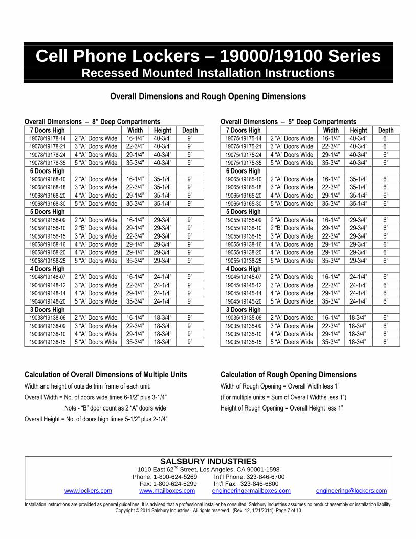
Overall Dimensions and Rough Opening Dimensions
Overall Dimensions – 8” Deep Compartments 7 Doors High Width Height Depth
19078/19178-14 2 “A” Doors Wide 16-1/4” 40-3/4” 9”
19078/19178-21 3 “A” Doors Wide 22-3/4” 40-3/4” 9”
19078/19178-24 4 “A” Doors Wide 29-1/4” 40-3/4” 9”
19078/19178-35 5 “A” Doors Wide 35-3/4” 40-3/4” 9”
6 Doors High
19068/19168-10 2 “A” Doors Wide 16-1/4” 35-1/4” 9”
19068/19168-18 3 “A” Doors Wide 22-3/4” 35-1/4” 9”
19068/19168-20 4 “A” Doors Wide 29-1/4” 35-1/4” 9”
19068/19168-30 5 “A” Doors Wide 35-3/4” 35-1/4” 9”
5 Doors High
19058/19158-09 2 “A” Doors Wide 16-1/4” 29-3/4” 9”
19058/19158-10 2 “B” Doors Wide 29-1/4” 29-3/4” 9”
19058/19158-15 3 “A” Doors Wide 22-3/4” 29-3/4” 9”
19058/19158-16 4 “A” Doors Wide 29-1/4” 29-3/4” 9”
19058/19158-20 4 “A” Doors Wide 29-1/4” 29-3/4” 9”
19058/19158-25 5 “A” Doors Wide 35-3/4” 29-3/4” 9”
4 Doors High
19048/19148-07 2 “A” Doors Wide 16-1/4” 24-1/4” 9”
19048/19148-12 3 “A” Doors Wide 22-3/4” 24-1/4” 9”
19048/19148-14 4 “A” Doors Wide 29-1/4” 24-1/4” 9”
19048/19148-20 5 “A” Doors Wide 35-3/4” 24-1/4” 9”
3 Doors High
19038/19138-06 2 “A” Doors Wide 16-1/4” 18-3/4” 9”
19038/19138-09 3 “A” Doors Wide 22-3/4” 18-3/4” 9”
19038/19138-10 4 “A” Doors Wide 29-1/4” 18-3/4” 9”
19038/19138-15 5 “A” Doors Wide 35-3/4” 18-3/4” 9”
Calculation of Overall Dimensions of Multiple Units
Width and height of outside trim frame of each unit:
Overall Width = No. of doors wide times 6-1/2” plus 3-1/4”
Note - “B” door count as 2 “A” doors wide
Overall Height = No. of doors high times 5-1/2” plus 2-1/4”
Overall Dimensions – 5” Deep Compartments 7 Doors High Width Height Depth
19075/19175-14 2 “A” Doors Wide 16-1/4” 40-3/4” 6”
19075/19175-21 3 “A” Doors Wide 22-3/4” 40-3/4” 6”
19075/19175-24 4 “A” Doors Wide 29-1/4” 40-3/4” 6”
19075/19175-35 5 “A” Doors Wide 35-3/4” 40-3/4” 6”
6 Doors High
19065/19165-10 2 “A” Doors Wide 16-1/4” 35-1/4” 6”
19065/19165-18 3 “A” Doors Wide 22-3/4” 35-1/4” 6”
19065/19165-20 4 “A” Doors Wide 29-1/4” 35-1/4” 6”
19065/19165-30 5 “A” Doors Wide 35-3/4” 35-1/4” 6”
5 Doors High
19055/19155-09 2 “A” Doors Wide 16-1/4” 29-3/4” 6”
19055/19138-10 2 “B” Doors Wide 29-1/4” 29-3/4” 6”
19055/19138-15 3 “A” Doors Wide 22-3/4” 29-3/4” 6”
19055/19138-16 4 “A” Doors Wide 29-1/4” 29-3/4” 6”
19055/19138-20 4 “A” Doors Wide 29-1/4” 29-3/4” 6”
19055/19138-25 5 “A” Doors Wide 35-3/4” 29-3/4” 6”
4 Doors High
19045/19145-07 2 “A” Doors Wide 16-1/4” 24-1/4” 6”
19045/19145-12 3 “A” Doors Wide 22-3/4” 24-1/4” 6”
19045/19145-14 4 “A” Doors Wide 29-1/4” 24-1/4” 6”
19045/19145-20 5 “A” Doors Wide 35-3/4” 24-1/4” 6”
3 Doors High
19035/19135-06 2 “A” Doors Wide 16-1/4” 18-3/4” 6”
19035/19135-09 3 “A” Doors Wide 22-3/4” 18-3/4” 6”
19035/19135-10 4 “A” Doors Wide 29-1/4” 18-3/4” 6”
19035/19135-15 5 “A” Doors Wide 35-3/4” 18-3/4” 6”
Calculation of Rough Opening Dimensions
Width of Rough Opening = Overall Width less 1”
(For multiple units = Sum of Overall Widths less 1”)
Height of Rough Opening = Overall Height less 1”

SALSBURY INDUSTRIES 1010 East 62
nd Street, Los Angeles, CA 90001-1598
Phone: 1-800-624-5269 Int’l Phone: 323-846-6700 Fax: 1-800-624-5299 Int’l Fax: 323-846-6800
www.lockers.com www.mailboxes.com [email protected] [email protected]
Installation instructions are provided as general guidelines. It is advised that a professional installer be consulted. Salsbury Industries assumes no product assembly or installation liability. Copyright © 2014 Salsbury Industries. All rights reserved. (Rev. 12, 1/21/2014) Page 8 of 10
Cell Phone Lockers – 19000/19100 Series Recessed Mounted Installation Instructions
Top View of Cell Phone Lockers in Wall
Side View of Cell Phone Lockers in Wall
SALSBURY INDUSTRIES 1010 East 62
nd Street, Los Angeles, CA 90001-1598
Phone: 1-800-624-5269 Int’l Phone: 323-846-6700 Fax: 1-800-624-5299 Int’l Fax: 323-846-6800
www.lockers.com www.mailboxes.com [email protected] [email protected]
Installation instructions are provided as general guidelines. It is advised that a professional installer be consulted. Salsbury Industries assumes no product assembly or installation liability. Copyright © 2014 Salsbury Industries. All rights reserved. (Rev. 12, 1/21/2014) Page 9 of 10
Cell Phone Lockers – 19000/19100 Series Identification Window Installation Instructions
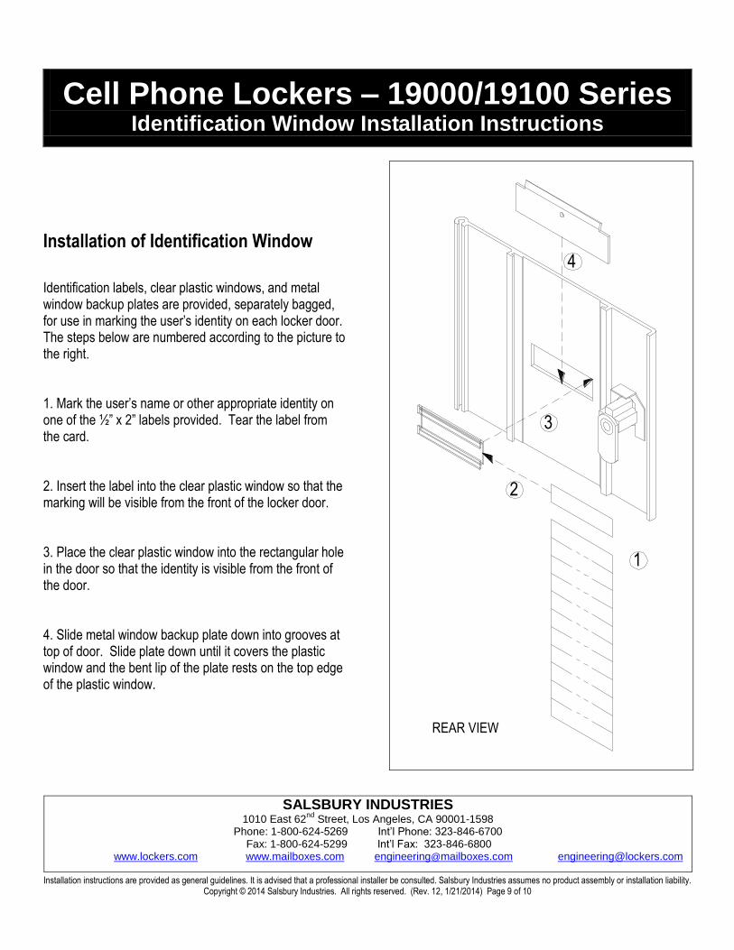
Installation of Identification Window
Identification labels, clear plastic windows, and metal window backup plates are provided, separately bagged, for use in marking the user’s identity on each locker door. The steps below are numbered according to the picture to the right. 1. Mark the user’s name or other appropriate identity on one of the ½” x 2” labels provided. Tear the label from the card. 2. Insert the label into the clear plastic window so that the marking will be visible from the front of the locker door. 3. Place the clear plastic window into the rectangular hole in the door so that the identity is visible from the front of the door. 4. Slide metal window backup plate down into grooves at top of door. Slide plate down until it covers the plastic window and the bent lip of the plate rests on the top edge of the plastic window.
2
3
4
1
REAR VIEW

SALSBURY INDUSTRIES 1010 East 62
nd Street, Los Angeles, CA 90001-1598
Phone: 1-800-624-5269 Int’l Phone: 323-846-6700 Fax: 1-800-624-5299 Int’l Fax: 323-846-6800
www.lockers.com www.mailboxes.com [email protected] [email protected]
Installation instructions are provided as general guidelines. It is advised that a professional installer be consulted. Salsbury Industries assumes no product assembly or installation liability. Copyright © 2014 Salsbury Industries. All rights reserved. (Rev. 12, 1/21/2014) Page 10 of 10
Cell Phone Lockers – 19000/19100 Series Resettable Combination Lock Operating & Resetting Instructions
The resettable combination lock is a durable and easy-to-use lock providing resettable combination access without the need for keys. Please read this entire page before use.
The lock has a four (4) digit combination setting. When the lock is locked (closed), a red indicator appears in a window next to the operation knob. When the lock is unlocked (open), a green indicator appears in the window.
There are two (2) modes of operation: fixed combination or resettable combination. In fixed combination mode, the lock is continually opened and closed with the same custom combination that was set. In the resettable combination mode, the combination may be changed after each time the lock is opened.
The factory preset combination is 0000. Master key operation may be used at any time to open a lock.
Setup for a Fixed Combination
1. If locked, turn the four (4) dials to the factory preset combination (0000) or the known combination that unlocks the lock.
2. Turn the operation knob clockwise 180 to the open position. The indicator in the window will turn from red to green.
3. Turn the reset/fix stem on the back of the lock from the “Fix” to the “Reset” position.
4. Returning to the front of the lock, set the desired custom fixed combination on the four (4) dials.
5. On the back of the lock, return the reset/fix button back to “Fix”.
The lock is now set to continuously open using the custom fixed
combination. After locking, scrambling the four (4) dials will secure
the contents.
Setup for a Resettable Combination
1. If locked, turn the four (4) dials to the factory preset combination (0000) or the known combination that unlocks the lock.
2. Turn the operation knob clockwise 180 to the open position. The indicator in the window will turn from red to green.
3. Turn the reset/fix stem on the back of the lock from the “Fix” to the “Reset” position. Leave the button in this position.
4. Close the door. Do not lock it.
The lock combination can now be resettable by the user setting their
own desired combination before turning the operation knob to the
locked position (red window indicator). After locking, scrambling
the four (4) dials will secure the contents.
Decode Operation
Used to determine lock combination.
1. Open the door. Use the master key if necessary.
2. Push the decode lever up and hold it in place. Rotate each of the dials on the front of the lock until it stops or there is a “click” sound. Release the decode lever.
3. Each dial will now be in the “open” combination position.
DECODE LEVER
RESET/FIX STEM
PUSH
RED/GREEN INDICATOR
WINDOW
FOUR (4) DIALS
OPERATION
KNOB