cello with neptune e-coder quick install guidee - ti … 1 general instructions the cello quick...
TRANSCRIPT

CEL
LO W
ITH
NEP
TUN
E E-
CO
DER
® Q
UIC
K IN
STA
LL G
UID
E
Cello with Neptune E-Coder®
Quick Install Guidee

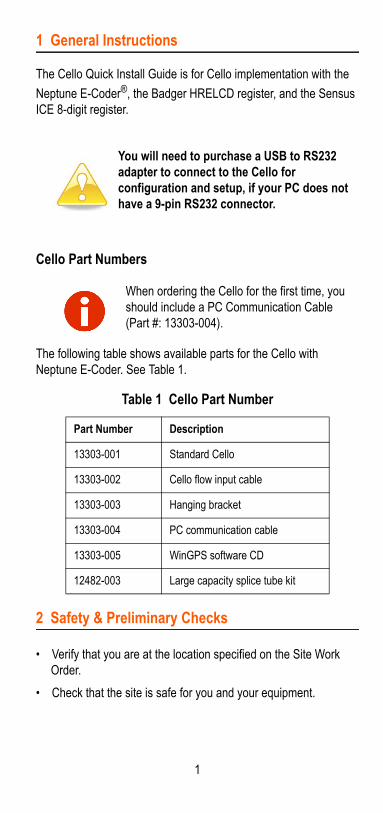
1 General Instructions
The Cello Quick Install Guide is for Cello implementation with the
Neptune E-Coder®, the Badger HRELCD register, and the Sensus ICE 8-digit register.
Cello Part Numbers
The following table shows available parts for the Cello with Neptune E-Coder. See Table 1.
2 Safety & Preliminary Checks
• Verify that you are at the location specified on the Site Work Order.
• Check that the site is safe for you and your equipment.
You will need to purchase a USB to RS232 adapter to connect to the Cello for configuration and setup, if your PC does not have a 9-pin RS232 connector.
When ordering the Cello for the first time, you should include a PC Communication Cable (Part #: 13303-004).
Table 1 Cello Part Number
Part Number Description
13303-001 Standard Cello
13303-002 Cello flow input cable
13303-003 Hanging bracket
13303-004 PC communication cable
13303-005 WinGPS software CD
12482-003 Large capacity splice tube kit
1

• Notify the customer of your presence and tell the customer that you must have access to the water meter.
• Confirm and/or update the Cello number on the Site Work Order.
3 Configuring the Cello
Install the WinGPS software and save the configuration files that are included in the manufacturer’s installation CD. If the configuration files are not found contact Neptune Customer Support.
To configure the Cello, complete the following steps.
When installing meters, follow any guidelines issued by your company in addition to those given in this guide. Never perform an installation during a lightning storm or under excessively wet conditions.
Before wiring the Cello to the register or registers, complete the configuration and setup process of the Cello. You can set up the Cello in the office before connecting to the register.
The Cello will need to send all identifying numbers to the data servers prior to reading the register data.
Domestic Wireless Voice Coverage maps are found at the following two links. Select the 2G coverage maps.
• Go to: http://www.att.com/maps/wireless-coverage.html#fbid=YfMhdJIrSq0
After completing the setup of the Cello, an email MUST be sent the next business day to [email protected] asking to enable the Neptune export for this Cello ID. The email must include the Cello ID.
2

Figure 1 Black Screw Cap
Figure 2 Connect Cello to Laptop
Accessing the WinGPS Software
To access the WinGPS software (Part #:13303-005) on the PC and set up the Cello, complete the following steps.
1 Remove the black screw cap from the Cello. See Figure 2.
2 Connect the Cello to the laptop using a PC 9-pin RS232 to 6-way B/H communication input cable (Part #:13303-004) with a serial to USB cable (not supplied). See Figure 2.
WinGPS software is compatible with the following:
• Windows XP®
• Windows Vista
• Windows 7 (32 or 64 bit)
• Windows 8 (32 or 64 bit)
3
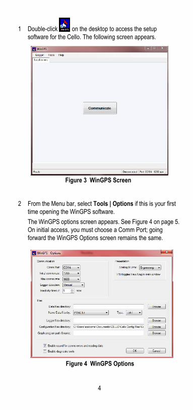
1 Double-click on the desktop to access the setup software for the Cello. The following screen appears.
Figure 3 WinGPS Screen
2 From the Menu bar, select Tools | Options if this is your first time opening the WinGPS software.
The WinGPS options screen appears. See Figure 4 on page 5. On initial access, you must choose a Comm Port; going forward the WinGPS Options screen remains the same.
Figure 4 WinGPS Options
4
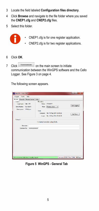
3 Locate the field labeled Configuration files directory.
4 Click Browse and navigate to the file folder where you saved the CNEP1.cfg and CNEP2.cfg files.
5 Select this folder.
6 Click OK.
7 Click on the main screen to initiate communication between the WinGPS software and the Cello Logger. See Figure 3 on page 4.
The following screen appears.
Figure 5 WinGPS - General Tab
• CNEP1.cfg is for one register application.
• CNEP2.cfg is for two register applications.
5

On the General Tab
1 Select Logger at the top of the screen, and then select Configure (or press Ctrl + C).
Figure 6 WinGPS - Logger
2 From the WinGPS folder, select one of the following files:
• CNEP1.cfg (one register application).
• CNEP2.cfg (two register applications).
3 Double-click the.cfg file, then click Configure to send the configuration to the Cello.
4 Type the following when configured:• Site Name (such as Hospital Cello 300 Main Street)• Customer Number (Utility Customer Number, such as the
Utility’s Zip Code)
Figure 7 Site Name and Customer Number
5 Click Save.
On the Channels Tab
On the Channels tab you have significant columns of data. See Figure 8 on page 8.
• The Channel column shows the Channel Name.
• The Range column shows the scale factor and unit of measure.
6

• The Live Input column shows the current read once a register is connected and polled.
• The Rate column shows the interval data timing.
The Communications Server populates the Channels tab with the correct information once the initial Config and Setup file is received.
Figure 8 WinGPS - Channels Tab
After connecting the register, click Live Input and the current read displays in the field to confirm Register to Cello connectivity. See Figure 9.
Figure 9 Live Input Button and Reading
The registers connected to the Cello are identified by the number on the Cello ID Label, as shown in Figure 10 on page 9.
The Cello ID with a 2 for HI and a 3 for LO are visible on the Cello Label. Use these numbers to identify the registers once they are imported into N_SIGHT™.
7

Figure 10 Cello ID Label
To edit the Channel fields:
1 Click Channel to highlight. See Figure 11
Figure 11 Channel Highlighted
2 Click Edit Channel. See Figure 12.
Figure 12 Edit Channel Button
Leave the Logging Rate as the default value. Changing can increase data charges. Look at the Ch Name and type the corresponding MIU ID from the Cello ID Label. Edit the Scale Factor field to match the utilities unit of measure, gal= gallons, cuf= cubic feet, etc. See Figure 12.
Figure 13 MIU ID and Scale Factor Fields
8

.
3 After editing is completed, click OK.
On the Remote Comms Tab
1 Select the Remote Comms tab.
The following screen appears.
Figure 14 WinGPS - Remote Comms Tab
2 Select the Operate modem every check box.
• Leave the drop-down selection as Day. This is the default.
• Select the time for the modem call in time. The default is 5:00 a.m.
Neptune recommends using the HI and LO numbers found on the Cello label for the MIU ID.
When connecting two registers, use the HI and LO numbers for the MIU ID.
When setting up the Cello, include the HI and LO ID numbers on a utility work order for reference.
9

3 Click the Retry Mode drop-down menu, and choose Repeat every 2 hours.
On the Index Tab
1 Select the Index tab.
The following screen appears.
Figure 15 WinGPS - Index Tab
2 Confirm the Index is formatted like the reading you are expect-ing.
The reading that comes from the register populates this field after it is connected.
All other values can be left as the defaults. Changing these to a more frequent reporting interval can reduce battery life and increase cellular data charges.
10

On the General Tab
1 Select the General tab.
The following screen appears.
Figure 16 WinGPS Complete Configuration
2 Click Adjust Clock to synchronize the clock with the PC.
3 Click Start Logging.
A WinGPS prompt appears to Clear Data and Start recording.
4 Choose Now or another specified time.
5 Leave the Monitor Comms after Start selected.The communications dialog appears for the duration of the Cello’s communications.
11
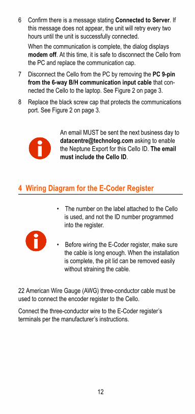
6 Confirm there is a message stating Connected to Server. If this message does not appear, the unit will retry every two hours until the unit is successfully connected.
When the communication is complete, the dialog displays modem off. At this time, it is safe to disconnect the Cello from the PC and replace the communication cap.
7 Disconnect the Cello from the PC by removing the PC 9-pin from the 6-way B/H communication input cable that con-nected the Cello to the laptop. See Figure 2 on page 3.
8 Replace the black screw cap that protects the communications port. See Figure 2 on page 3.
4 Wiring Diagram for the E-Coder Register
22 American Wire Gauge (AWG) three-conductor cable must be used to connect the encoder register to the Cello.
Connect the three-conductor wire to the E-Coder register’s terminals per the manufacturer’s instructions.
An email MUST be sent the next business day to [email protected] asking to enable the Neptune Export for this Cello ID. The email must include the Cello ID.
• The number on the label attached to the Cello is used, and not the ID number programmed into the register.
• Before wiring the E-Coder register, make sure the cable is long enough. When the installation is complete, the pit lid can be removed easily without straining the cable.
12
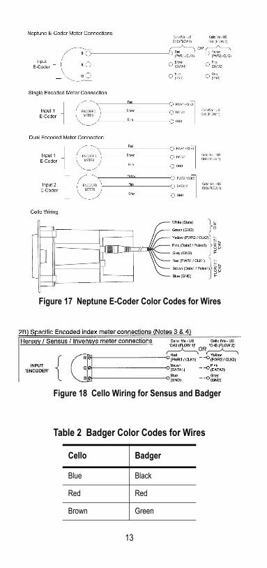
Figure 17 Neptune E-Coder Color Codes for Wires
Figure 18 Cello Wiring for Sensus and Badger
Table 2 Badger Color Codes for Wires
Cello Badger
Blue Black
Red Red
Brown Green
13

Figure 19 Cello Wires
5 Wiring the E-Coder and Cello
Figure 20 E-Coder and Cello Wiring
Figure 21 Scotchlok Connector
All encoder terminal connections that are not pre-wired and potted must be covered with
Novagard (G661) or Dow® Corning Compound 4.
1 Use a 3M Scotchlok Type UR connector to connect the MIU wires to the encoder wires.
2 Hold the Scotchlok connec-tor between your index fin-ger and thumb with the red cap facing down. See Figure 21.
14

Figure 22 Seating Connector Wires
Figure 23 UR Crimping Tool
Figure 24 Improper Connections
Do not strip colored insulation from the wires or strip and twist bare wires prior to inserting the connector. Insert insulated colored wires directly into the Scotchlok connector.
3 Using a non-stripped black wire from the pigtail and a non-stripped red wire from the Cello, insert the wires into the Scotch-lok connector until fully seated in connector. See Figure 22
4 Place the connector (red cap side down) between the jaws of the UR crimp-ing tool as shown in Figure 23
5 Check to ensure that the wires are still fully seated in the connector before crimping the connector. Figure 24 shows improper connections as the wires are not fully seated.
Red wires not fully seated
15

6 Squeeze the connector firmly with the proper crimping tool until you hear a pop and gel leaks out the end of the connector.
7 Repeat steps 2 through 6 for each color wire.
Figure 25 All Three Color Wires Connected
Connecting the Splice Tube
To finish the installation of the Scotchloks, complete the following steps to install the Connector King Splice Tube (Kit Part Number 12482-003).
Figure 26 Splice Tube
When all three color wires are correctly seated and connected in the Scotchloks, the unit is properly wired. See Figure 25
1 Take all three connected Scotchloks and push them into the splice tube until fully covered by the silicone grease. See Figure 26.
Neptune recommends the Large Capacity King Splice Tube Kit (PN 12482-003) for use with the Cello communication input cable.
Splice Tube
16

Figure 27 Black Wires in Slots
3 Snap the cover closed, making sure that both black wires are properly seated in the slots of the splice tube.
6 Configuring N_SIGHT™ R900® Host Software to Process Cello Data
Setting Up the FTP Host Information
In N_SIGHT R900, complete the following.
1 Click Utilities.
2 Click Table Maintenance.
3 Click FTP Host Information from the drop-down selection list.
2 Separate each black wire, then place them in the slots on each side of the splice tube as shown in Figure 27.
Neptune Customer Support MUST be contacted prior to setting up the host software to confirm software version and generate a user name and password for the secure FTP server.
You must have the R900® Gateway module activated in your host software in order for this capability to be available. Contact Customer Support at (800) 647-4832 to get further information regarding the activation of additional modules.
17
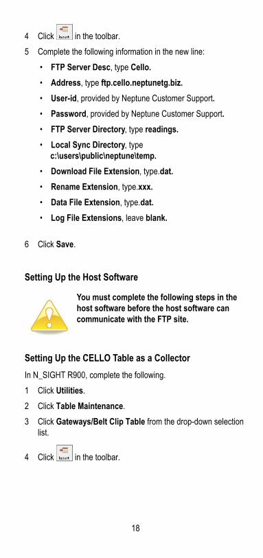
4 Click in the toolbar.
5 Complete the following information in the new line:
• FTP Server Desc, type Cello.
• Address, type ftp.cello.neptunetg.biz.
• User-id, provided by Neptune Customer Support.
• Password, provided by Neptune Customer Support.
• FTP Server Directory, type readings.
• Local Sync Directory, typec:\users\public\neptune\temp.
• Download File Extension, type.dat.
• Rename Extension, type.xxx.
• Data File Extension, type.dat.
• Log File Extensions, leave blank.
6 Click Save.
Setting Up the Host Software
Setting Up the CELLO Table as a Collector
In N_SIGHT R900, complete the following.
1 Click Utilities.
2 Click Table Maintenance.
3 Click Gateways/Belt Clip Table from the drop-down selection list.
4 Click in the toolbar.
You must complete the following steps in the host software before the host software can communicate with the FTP site.
18
19
5 Complete the following information in the new line:
• Serial Number, type CELLO.
• Collector Description, type CELLO.
• Address (optional), type the address.
• City (optional), type the city.
• State (optional), type the state.
• Zip (optional), type the zip code.
• Site ID, type the assigned site ID provided by Neptune.
• Hardware Version, select V1.
• FTP Server, select CELLO.
6 Click Save.
7 Click on the tool bar, and then click OK to save the configuration settings.
Enabling Gateway File Processing Events
1 Click Utilities.
2 Click the Gateway tab.
3 Click Gateway File Processing Event Enabled.
4 Click Save.
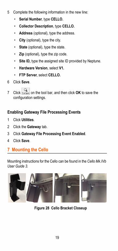
7 Mounting the Cello
Mounting instructions for the Cello can be found in the Cello Mk.IVb User Guide 3.
Figure 28 Cello Bracket Closeup

8 Checklist
Before leaving the installation site, be sure to do the following.
9 Contact Information
Within the United States, Neptune Customer Support is available Monday through Friday, 8:00 a.m. to 6:00 p.m. Eastern Standard Time, by telephone or fax.
To contact Customer Support by phone, call (800) 647-4832. If all Support Technicians are helping other customers, your call will be routed to the Customer Support voice mail system. Please leave your name, the name of your company, and your telephone number. Your call will be returned during business hours in the order it was received.
To contact Customer Support by fax, send a description of your problem to (334) 283-7497. Please include on the fax cover sheet the best time of day for a Support Technician to contact you. To contact Customer Support by email, send your letter to the following address: [email protected].
Notes
Record the MIU ID for each register.
Verify that you have followed all requirements in this Quick Install Guide.
Verify that you have recorded all required information.
Clean up any installation debris.
Verify that the requirements of the site work order have been completed.
Let the customer know you are finished or when you will return to complete your work if you are unable to finish in one day.
20


neptunetg.com
Neptune Technology Group Inc.1600 Alabama Highway 229Tallassee, AL 36078USATel: (800) 633-8754Fax: (334)283-7293
Neptune Technology Group (Canada) Ltd.7275 West Credit AvenueMississauga, OntarioL5N 5M9CanadaTel: (905) 858-4211Fax: (905) 858-0428
Neptune Technology Group Inc.Ejército Nacional No. 418Piso 12, Desp. 1201-1202Col. Chapultepec MoralesDelegación Miguel Hidalgo11570 México, Distrito FederalTel: (525) 55203 5294 / (525) 55203 5708Fax: (525) 55203 6503
QI Cello 09.14 Part No. 13303-006© Copyright 2013-2014, Neptune Technology Group Inc.Neptune is a registered trademark of Neptune Technology Group Inc.
Take Control