cellular and mobile communications · diversity receiver in co-channel interference –different...
TRANSCRIPT
CELLULAR AND MOBILE COMMUNICATIONS
by
VIDYA SAGAR POTHARAJU
Associate Professor,
Dept of ECE,
VBIT.
August 3, 2018
UNIT II Syllabus
CO-CHANNEL INTERFERENCE
Measurement of real time Co-channel interference, Design of antenna system, Antenna
parameters and their effects, Diversity technique- Space diversity, Polarization diversity,
Frequency diversity, Time diversity.
NON CO-CHANNEL INTERFERENCE
Adjacent channel interference, Near end far end interference, cross talk, Effects on coverage
and interference by power decrease, Antenna height decrease, Effects of cell site
components.
August 3, 2018 VIDYA SAGAR P 2
Co-Channel Interference
•Frequency reuse - there are several cells that use the same set of frequencies
co-channel cells
co-channel interference
•To reduce co-channel interference, co-channel cell must be separated by a minimum distance.
•When the size of the cell is approximately the same
co-channel interference is independent of the transmitted power
co-channel interference is a function of
R: Radius of the cell
D: distance to the center of the nearest co-channel cell
•Increasing the ratio Q=D/R, the interference is reduced.
•Q (co-channel interference reduction method) is called the co-channel reuse ratio
August 3, 2018 VIDYA SAGAR P 3
Co-channel Interference Reduction Factor
Q= D/R
D = f(KI, C/I)
where KI is the number of co channel interfering cells in the first tier and
C/I is the received carrier‐to‐interference ratio at the desired mobile receiver
August 3, 2018 VIDYA SAGAR P 4

Real time Co-Channel Interference
Signal is
Interference is
The received signal is
Where
And
August 3, 2018 VIDYA SAGAR P 5
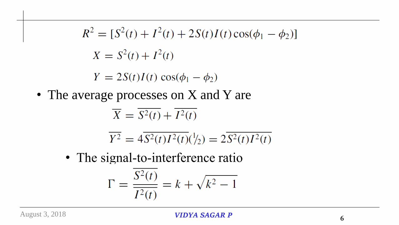
• The average processes on X and Y are
• The signal‐to‐interference ratio
August 3, 2018 VIDYA SAGAR P 6
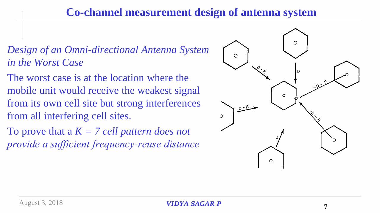
Co-channel measurement design of antenna system
Design of an Omni-directional Antenna System
in the Worst Case
The worst case is at the location where the
mobile unit would receive the weakest signal
from its own cell site but strong interferences
from all interfering cell sites.
To prove that a K = 7 cell pattern does not
provide a sufficient frequency‐reuse distance
August 3, 2018 VIDYA SAGAR P 7
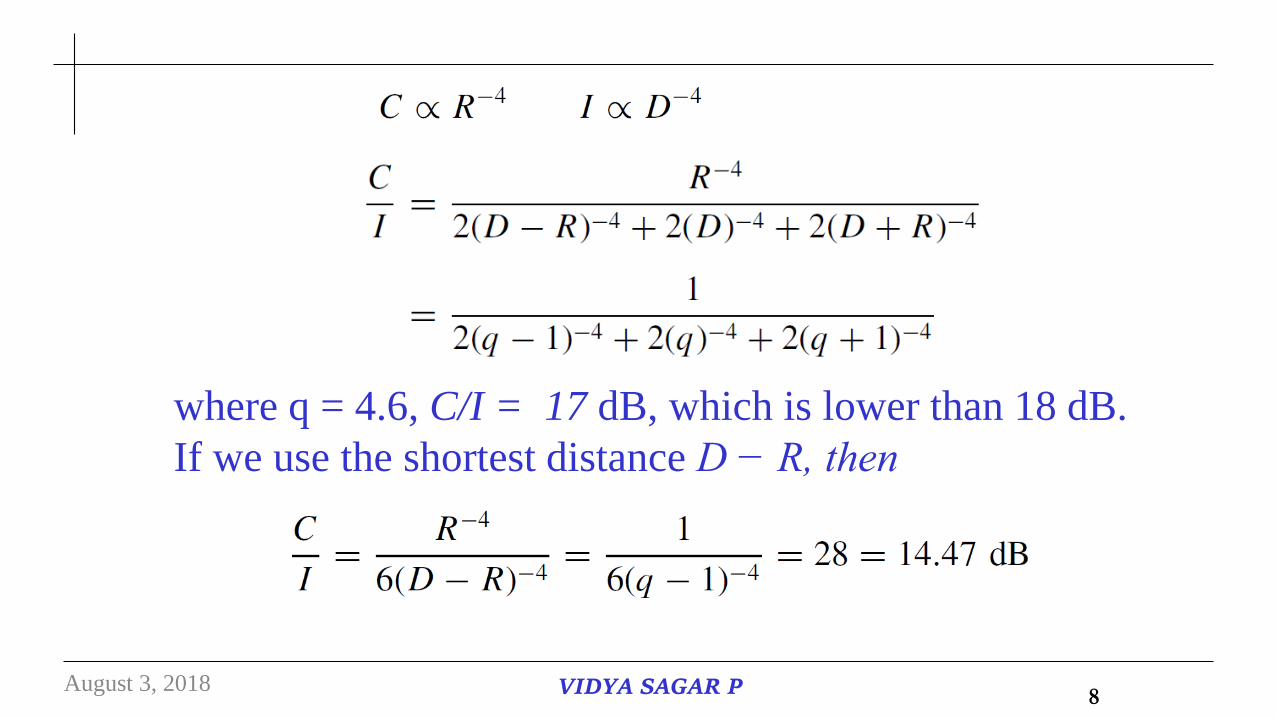
where q = 4.6, C/I = 17 dB, which is lower than 18 dB.
If we use the shortest distance D − R, then
August 3, 2018 VIDYA SAGAR P 8
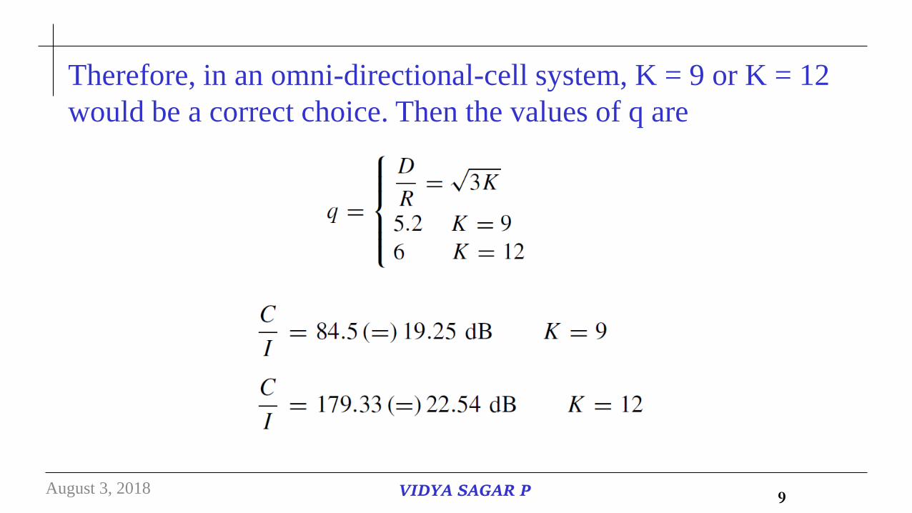
Therefore, in an omni-directional-cell system, K = 9 or K = 12
would be a correct choice. Then the values of q are
August 3, 2018 VIDYA SAGAR P 9
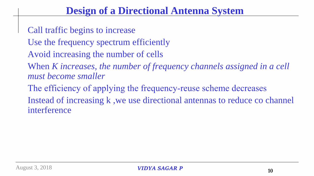
Design of a Directional Antenna System
Call traffic begins to increase
Use the frequency spectrum efficiently
Avoid increasing the number of cells
When K increases, the number of frequency channels assigned in a cell must become smaller
The efficiency of applying the frequency‐reuse scheme decreases
Instead of increasing k ,we use directional antennas to reduce co channel interference
August 3, 2018 VIDYA SAGAR P 10
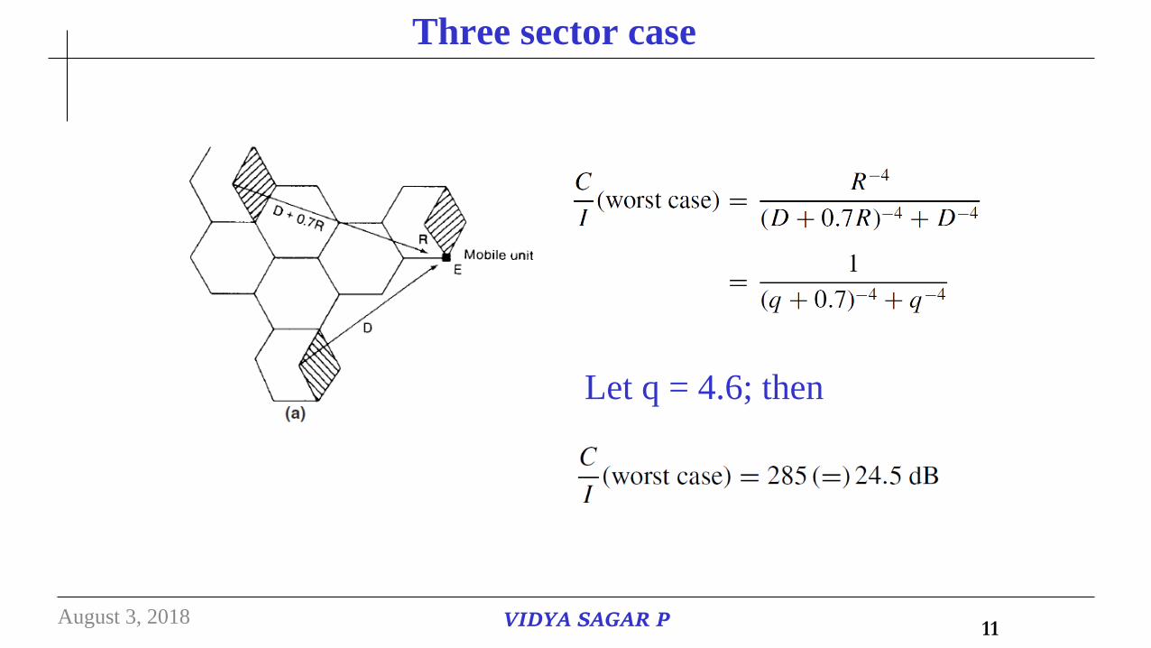
Three sector case
Let q = 4.6; then
August 3, 2018 VIDYA SAGAR P 11
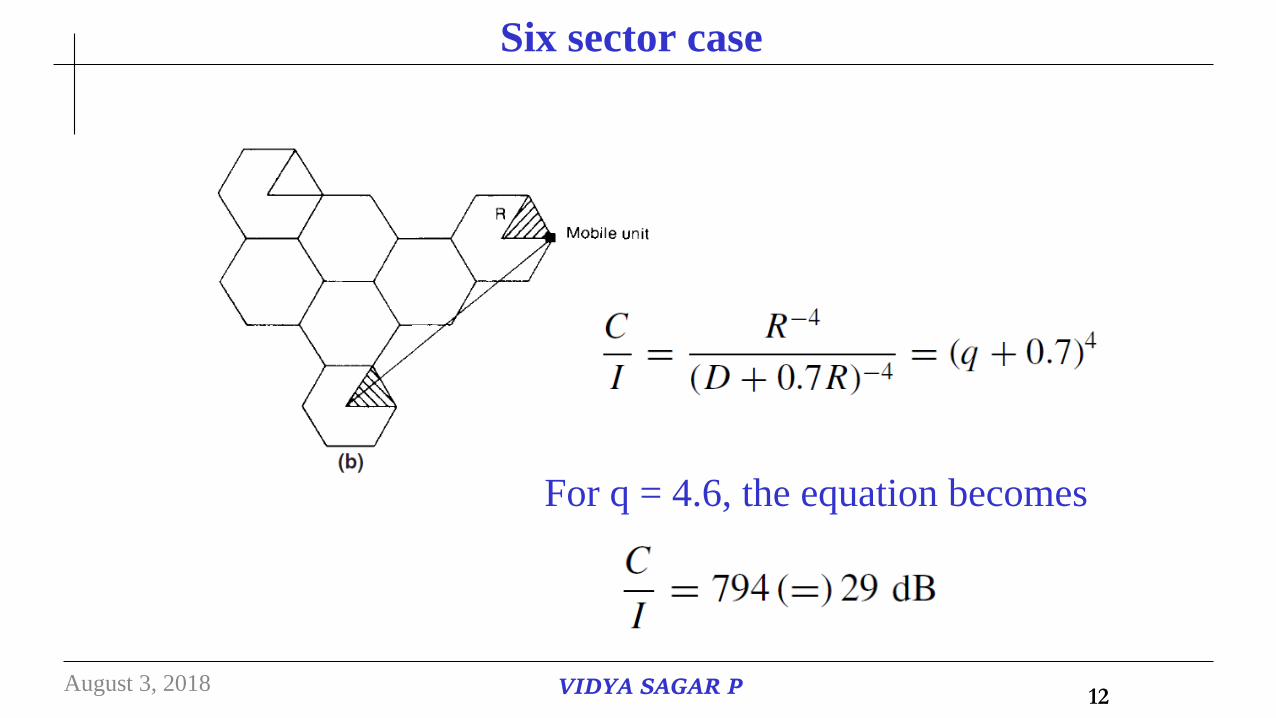
Six sector case
For q = 4.6, the equation becomes
August 3, 2018 VIDYA SAGAR P 12
Diversity Receiver In Co-Channel Interference –Different Types
Diversity: It is the technique used to compensate for fading channel
impairments. It is implemented by using two or more receiving antennas.
Diversity is usually employed to reduce the depth and duration of the fades
experienced by a receiver in a flat fading channel.
These techniques can be employed at both base station and mobile receivers.
Types of Diversity
Spatial or antenna diversity → most common
•Use multiple Rx antennas in mobile or base station
•Even small antenna separation (∝ λ ) changes phase of signal → constructive /destructive
nature is changed
Other diversity types → polarization, frequency, & time diversity
August 3, 2018 VIDYA SAGAR P 13
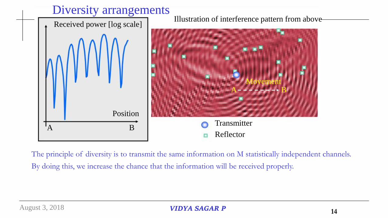
Diversity arrangements Illustration of interference pattern from above
Received power [log scale]
Movement
Position
A B
A B
Transmitter
Reflector
The principle of diversity is to transmit the same information on M statistically independent channels.
By doing this, we increase the chance that the information will be received properly.
August 3, 2018 VIDYA SAGAR P 14
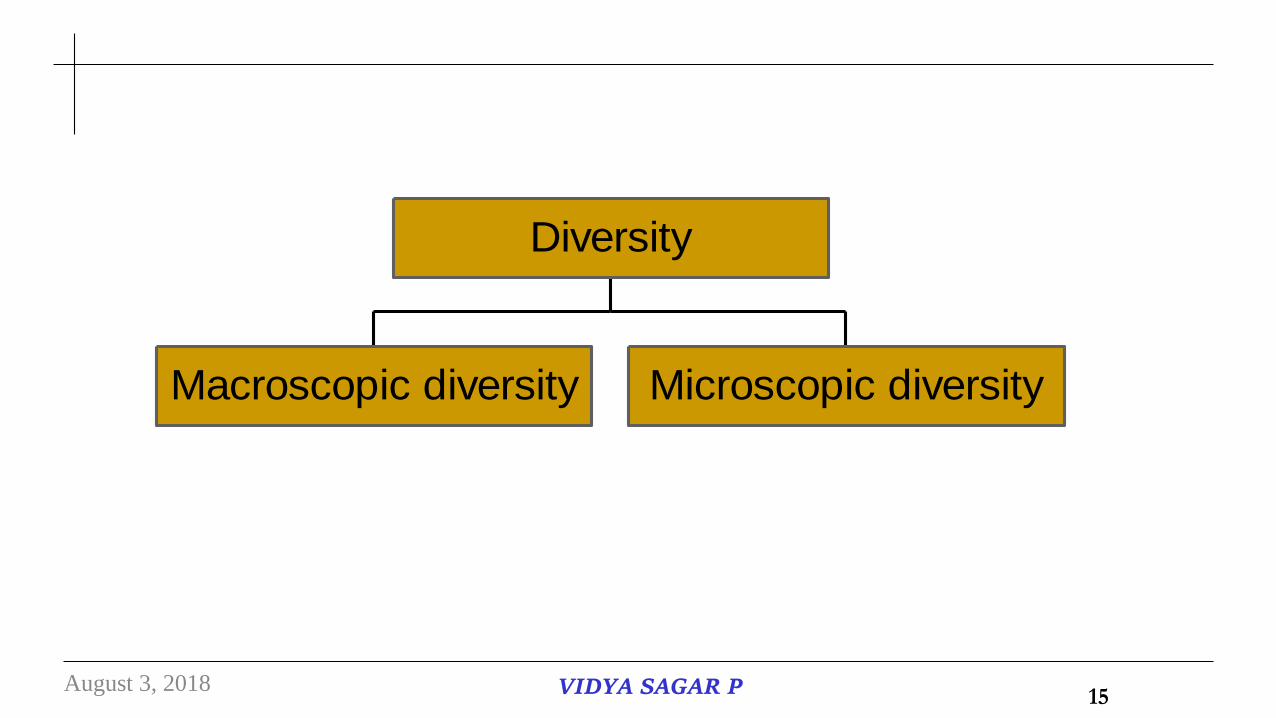
Macroscopic diversity Microscopic diversity
Diversity
August 3, 2018 VIDYA SAGAR P 15
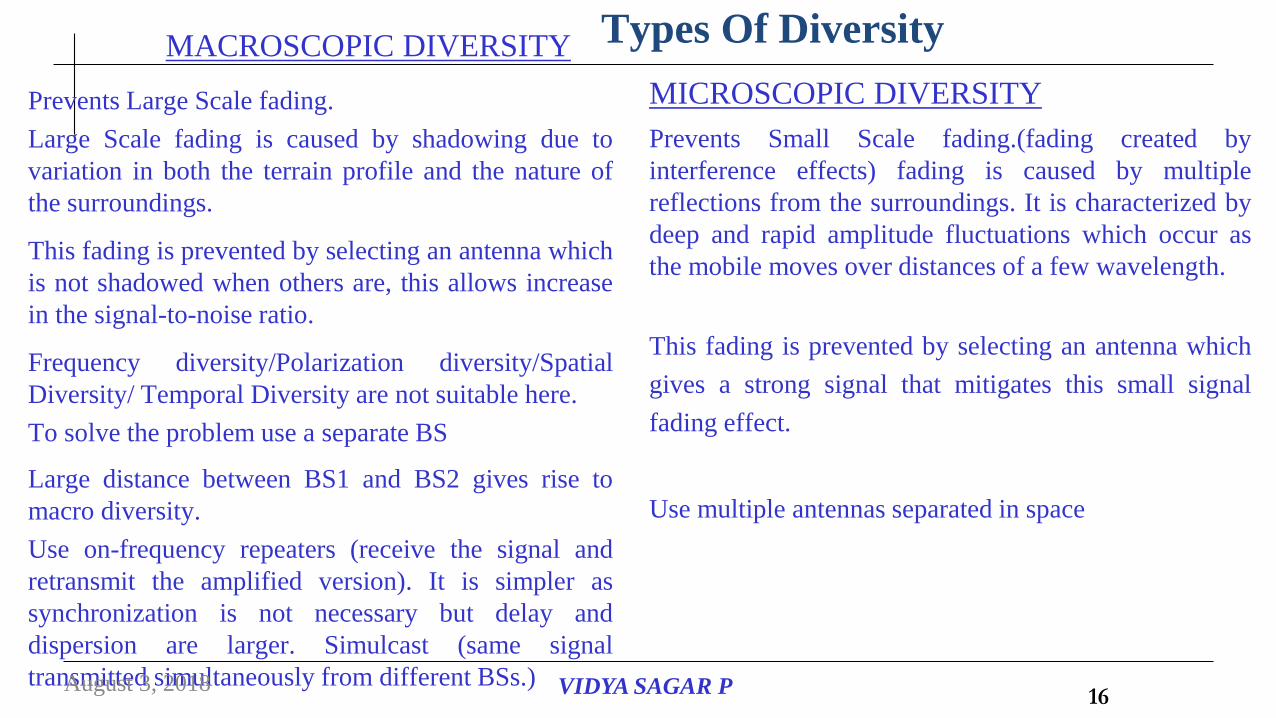
Types Of DiversityMACROSCOPIC DIVERSITY
Prevents Large Scale fading.
Large Scale fading is caused by shadowing due to
variation in both the terrain profile and the nature of
the surroundings.
This fading is prevented by selecting an antenna which
is not shadowed when others are, this allows increase
in the signal-to-noise ratio.
Frequency diversity/Polarization diversity/Spatial
Diversity/ Temporal Diversity are not suitable here.
To solve the problem use a separate BS
Large distance between BS1 and BS2 gives rise to
macro diversity.
Use on-frequency repeaters (receive the signal and
retransmit the amplified version). It is simpler as
synchronization is not necessary but delay and
dispersion are larger. Simulcast (same signal
transmitted simultaneously from different BSs.)
MICROSCOPIC DIVERSITY
Prevents Small Scale fading.(fading created by
interference effects) fading is caused by multiple
reflections from the surroundings. It is characterized by
deep and rapid amplitude fluctuations which occur as
the mobile moves over distances of a few wavelength.
This fading is prevented by selecting an antenna which
gives a strong signal that mitigates this small signal
fading effect.
Use multiple antennas separated in space
August 3, 2018 VIDYA SAGAR P 16

Microscopic diversity Techniques
Spatial Diversity (several antenna elements separated in space)
Temporal Diversity (repetition of the transmit signal at different times)
Frequency Diversity (transmission of the signal on different frequencies)
Angular Diversity (multiple antennas with different antenna patterns)
Polarization Diversity (multiple antennas receiving different polarizations)
August 3, 2018 VIDYA SAGAR P 17
August 3, 2018 VIDYA SAGAR P 18

August 3, 2018 VIDYA SAGAR P 19
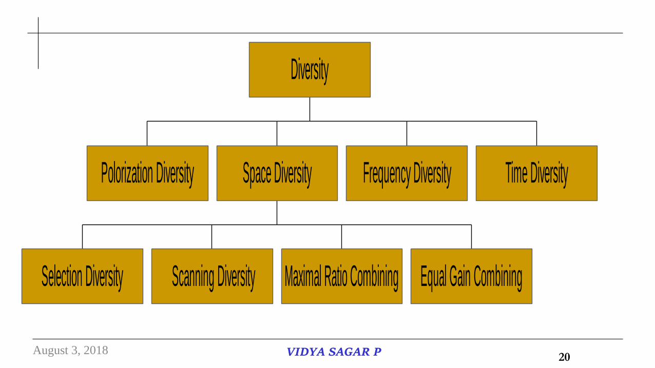
Polorization Diversity
Selection Diversity Scanning Diversity Maximal Ratio Combining Equal Gain Combining
Space Diversity Frequency Diversity Time Diversity
Diversity
August 3, 2018 VIDYA SAGAR P 20

Polarization Diversity
Principle :
Polarization diversity relies on the decorrelation of the two receive ports to achieve diversity gain. The two receiver ports must remain cross-polarized.
August 3, 2018 VIDYA SAGAR P 21

Selection Diversity Scanning Diversity Maximal Ratio Combining Equal Gain Combining
Space Diversity
August 3, 2018 VIDYA SAGAR P 22
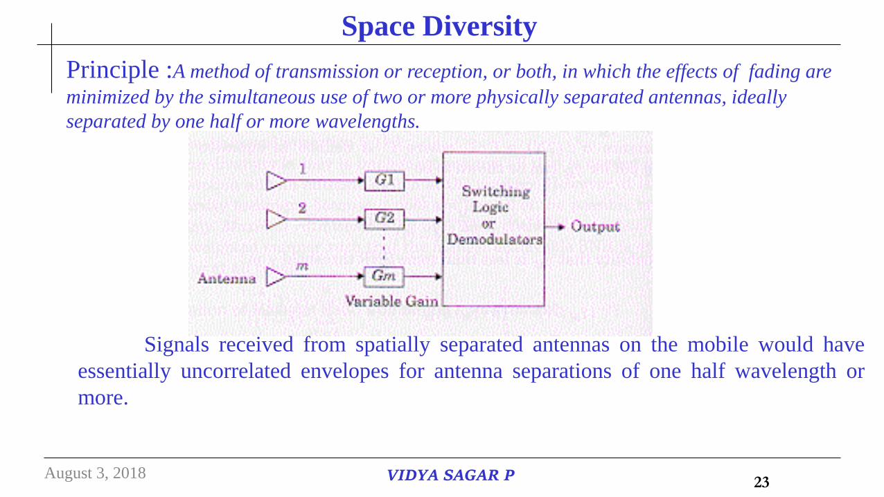
Signals received from spatially separated antennas on the mobile would have
essentially uncorrelated envelopes for antenna separations of one half wavelength or
more.
Space Diversity
Principle :A method of transmission or reception, or both, in which the effects of fading are
minimized by the simultaneous use of two or more physically separated antennas, ideally
separated by one half or more wavelengths.
August 3, 2018 VIDYA SAGAR P 23
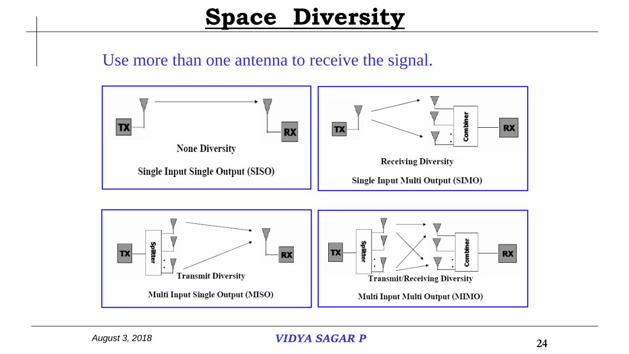
Use more than one antenna to receive the signal.
Space Diversity
August 3, 2018 VIDYA SAGAR P 24
•Selection diversity offers an average improvement in the link margin without requiring additional transmitter power or sophisticated receiver circuitry.
•Selection diversity is easy to implement because all that is needed is a side monitoring station and an antenna switch at the receiver.
•However it is not an optimal diversity technique because it does not use all of the possible branches simultaneously.
•In practice the SNR is measured as (S+N)/N, since it is difficult to measure SNR.
Selection Diversity Technique :
Principle :Selecting the best signal among all the signals received from different
braches at the receiving end.
August 3, 2018 VIDYA SAGAR P 25

August 3, 2018 VIDYA SAGAR P 26
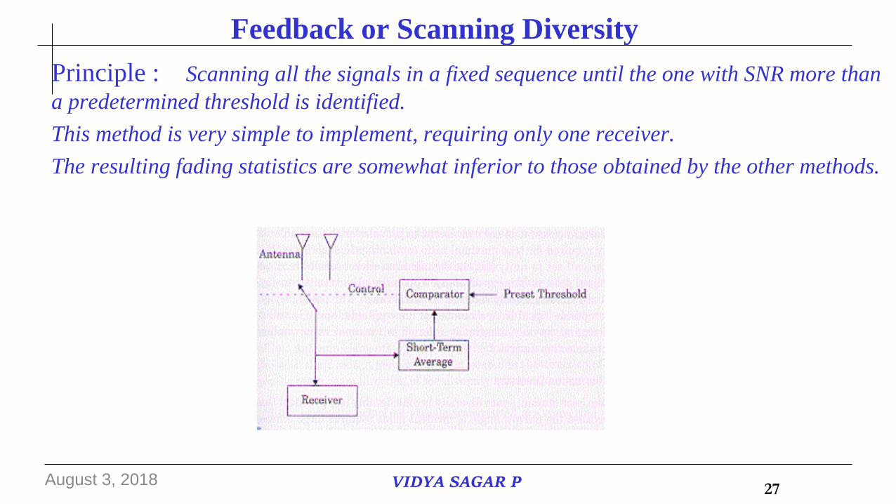
Feedback or Scanning Diversity
Principle : Scanning all the signals in a fixed sequence until the one with SNR more than
a predetermined threshold is identified.
This method is very simple to implement, requiring only one receiver.
The resulting fading statistics are somewhat inferior to those obtained by the other methods.
August 3, 2018 VIDYA SAGAR P 27
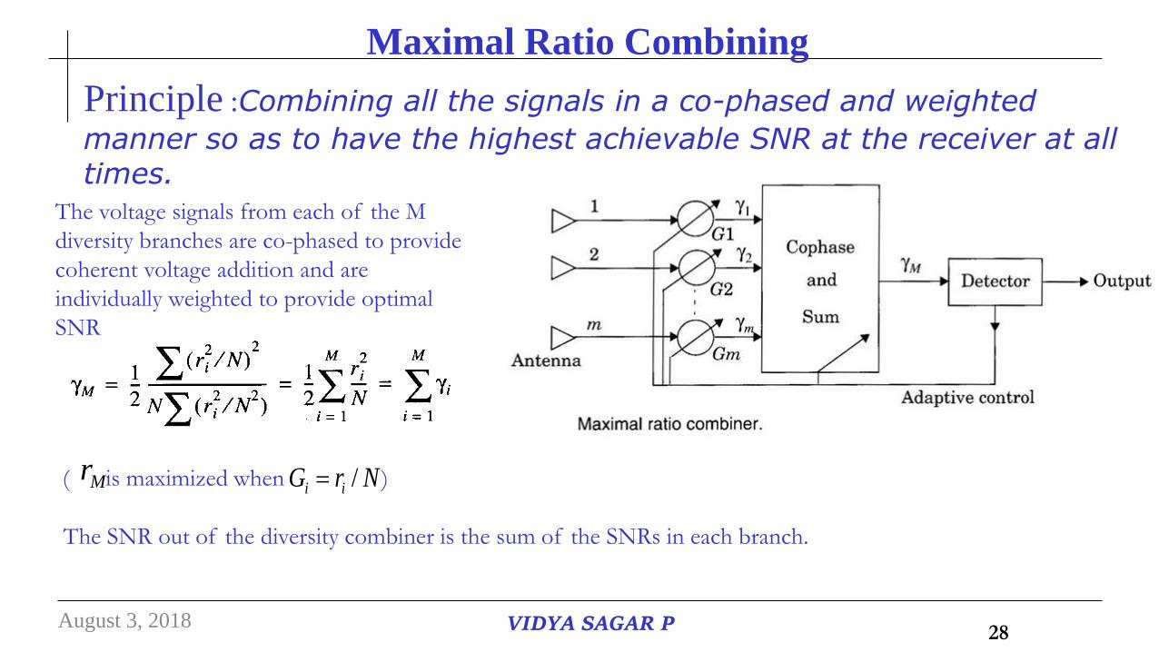
Maximal Ratio Combining
Principle :Combining all the signals in a co-phased and weighted
manner so as to have the highest achievable SNR at the receiver at all times.
The voltage signals from each of the M
diversity branches are co-phased to provide
coherent voltage addition and are
individually weighted to provide optimal
SNR
( is maximized when )Mr NrG ii /
The SNR out of the diversity combiner is the sum of the SNRs in each branch.
August 3, 2018 VIDYA SAGAR P 28

Equal Gain Combining
Principle :Combining all the signals in a co-phased manner with
unity weights for all signal levels so as to have the highest achievable SNR at the receiver at all times.
Combine multiple signals into one
G = 1, but the phase is adjusted for each received signal.
The signal from each branch are co-phased vectors add in-phase.
Better performance than selection diversity
August 3, 2018 VIDYA SAGAR P 29
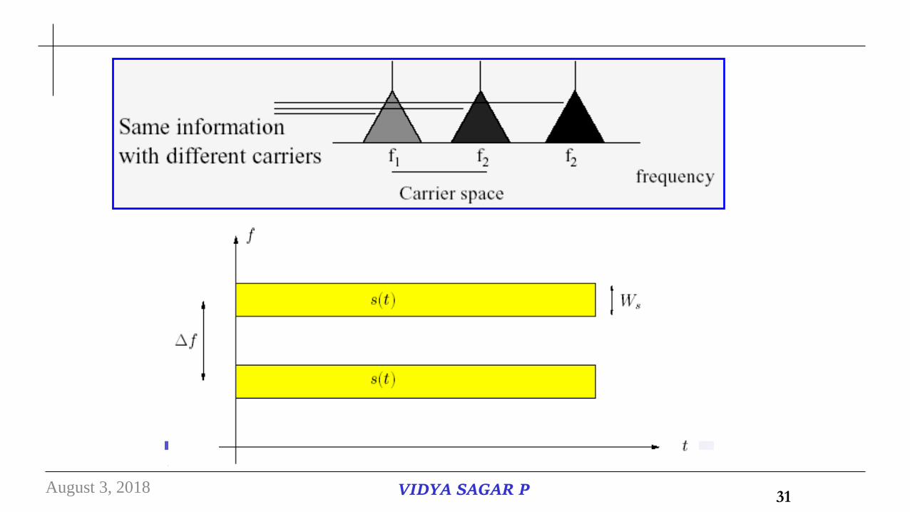
•The rational behind this technique is that frequencies separated by more than the coherence
bandwidth of the channel will not experience the same fade.
•The probability of simultaneous fade will be the product of the individual fading probabilities.
•This is often employed in microwave LOS links which carry several channels in a frequency division
multiplex mode(FDM).
Frequency Diversity
Principle :The same information signal is transmitted and received
simultaneously on two or more independent fading carrier frequencies.
August 3, 2018 VIDYA SAGAR P 30
August 3, 2018 VIDYA SAGAR P 31
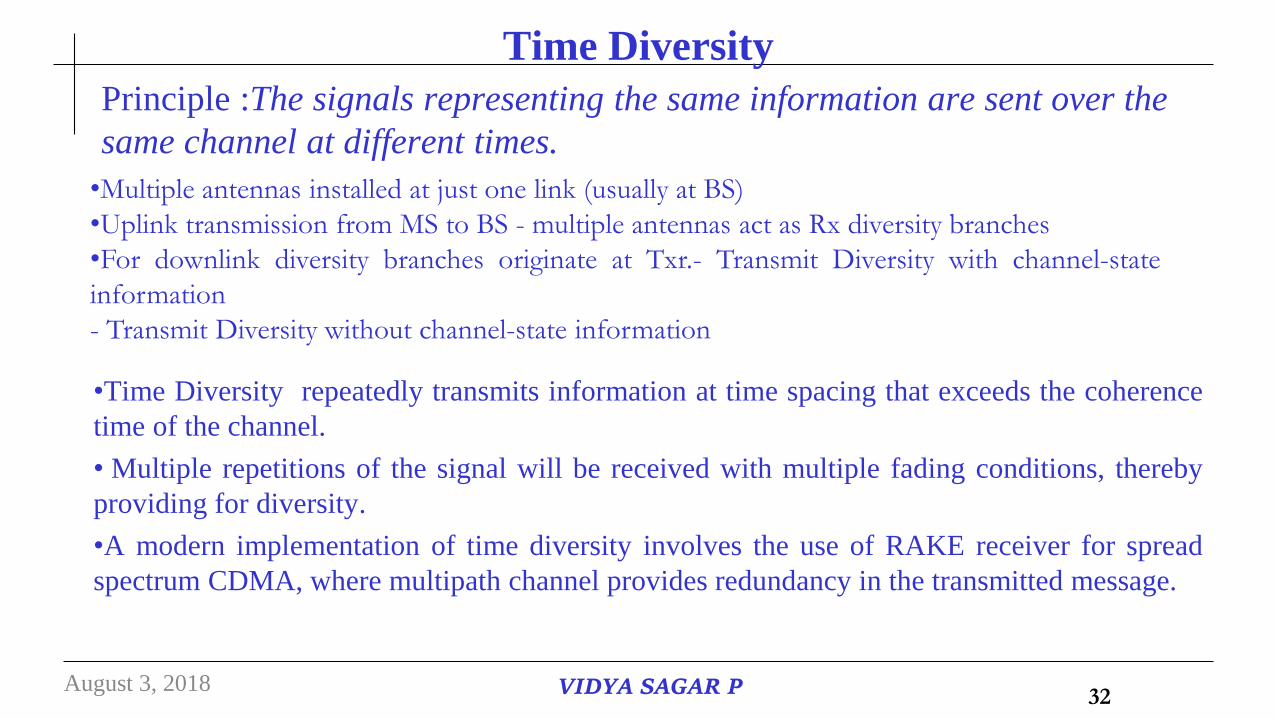
Time Diversity
Principle :The signals representing the same information are sent over the
same channel at different times.
•Time Diversity repeatedly transmits information at time spacing that exceeds the coherence
time of the channel.
• Multiple repetitions of the signal will be received with multiple fading conditions, thereby
providing for diversity.
•A modern implementation of time diversity involves the use of RAKE receiver for spread
spectrum CDMA, where multipath channel provides redundancy in the transmitted message.
•Multiple antennas installed at just one link (usually at BS)
•Uplink transmission from MS to BS - multiple antennas act as Rx diversity branches
•For downlink diversity branches originate at Txr.- Transmit Diversity with channel-state
information
- Transmit Diversity without channel-state information
August 3, 2018 VIDYA SAGAR P 32

The RAKE Rx is a time diversity Rx that collects time-shifted versions of
the original Tx signal
August 3, 2018 VIDYA SAGAR P 33
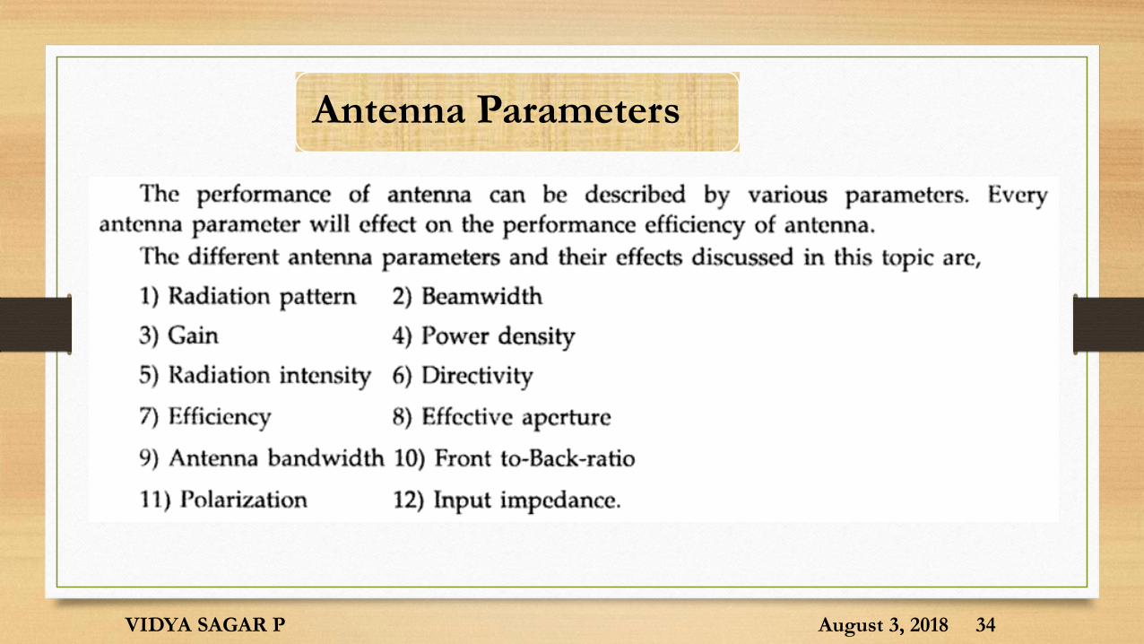
Antenna Parameters
August 3, 2018VIDYA SAGAR P 34
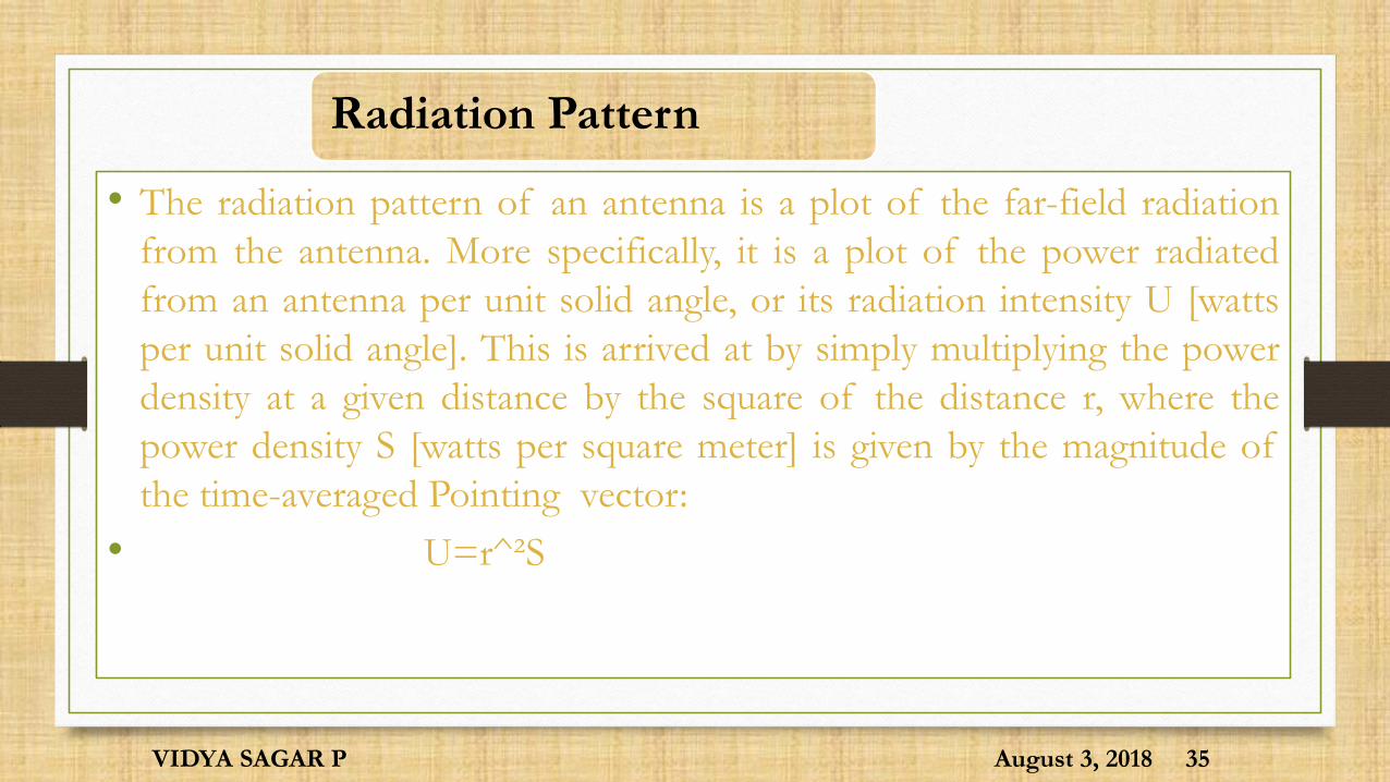
Radiation Pattern
• The radiation pattern of an antenna is a plot of the far-field radiation
from the antenna. More specifically, it is a plot of the power radiated
from an antenna per unit solid angle, or its radiation intensity U [watts
per unit solid angle]. This is arrived at by simply multiplying the power
density at a given distance by the square of the distance r, where the
power density S [watts per square meter] is given by the magnitude of
the time-averaged Pointing vector:
• U=r^²S
August 3, 2018VIDYA SAGAR P 35

August 3, 2018VIDYA SAGAR P 36

Directivity
• The directivity D of an antenna, a function of direction
• is defined by the ratio of radiation intensity of antenna in direction to
the mean radiation intensity in all directions.
August 3, 2018VIDYA SAGAR P 37

Radiation Resistance and Efficiency
• The resistive part of the antenna impedance is split into two parts, a
radiation resistance Rr and a loss resistance Rl. The power dissipated in
the radiation resistance is the power actually radiated by the antenna, and
the loss resistance is power lost within the antenna itself. This may be
due to losses in either the conducting or the dielectric parts of the
antenna. Radiation efficiency e of the antenna as e is the ratio of power
radiated to the power accepted by antenna
• antenna with high radiation efficiency therefore has high associated
radiation resistance compared with the losses. The antenna is said to be
resonant if its input reactance Xa =0.
August 3, 2018VIDYA SAGAR P 38
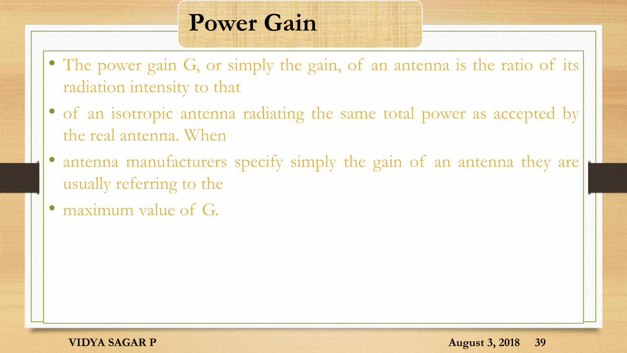
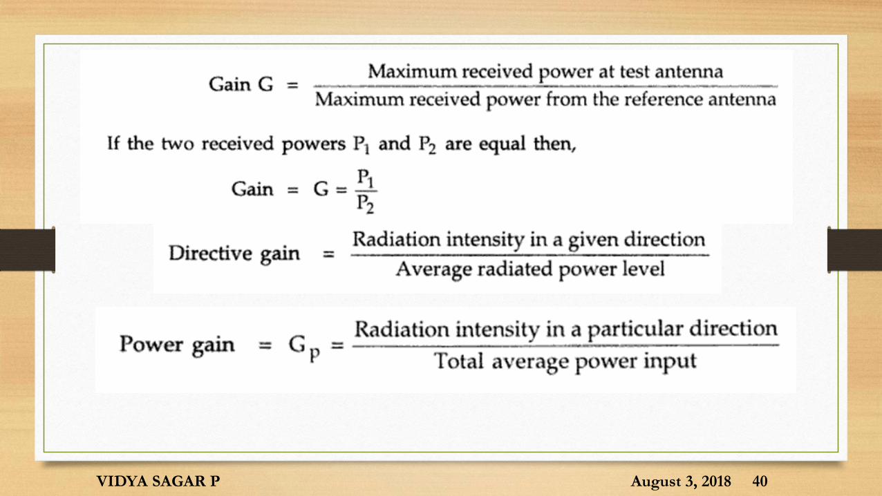
Power Gain
• The power gain G, or simply the gain, of an antenna is the ratio of its
radiation intensity to that
• of an isotropic antenna radiating the same total power as accepted by
the real antenna. When
• antenna manufacturers specify simply the gain of an antenna they are
usually referring to the
• maximum value of G.
August 3, 2018VIDYA SAGAR P 39
August 3, 2018VIDYA SAGAR P 40
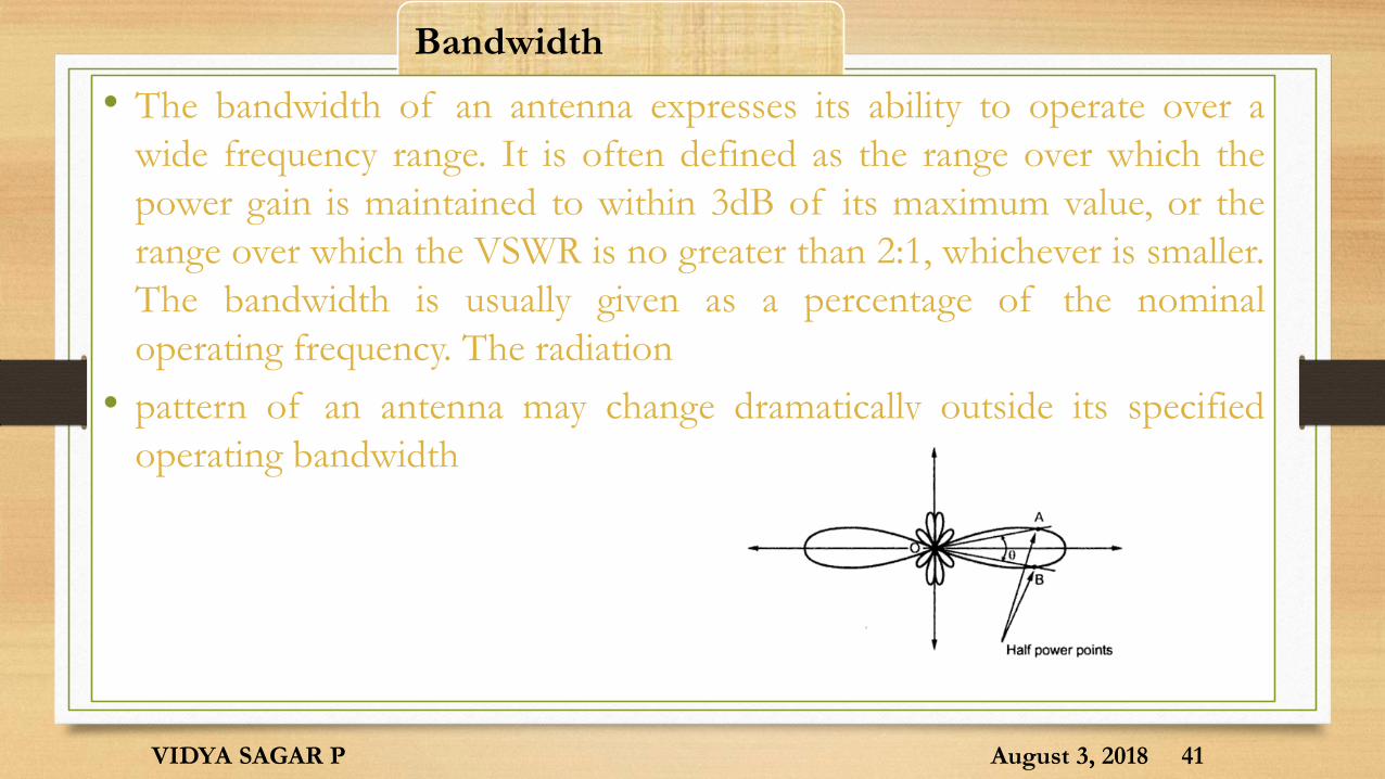
Bandwidth
• The bandwidth of an antenna expresses its ability to operate over a
wide frequency range. It is often defined as the range over which the
power gain is maintained to within 3dB of its maximum value, or the
range over which the VSWR is no greater than 2:1, whichever is smaller.
The bandwidth is usually given as a percentage of the nominal
operating frequency. The radiation
• pattern of an antenna may change dramatically outside its specified
operating bandwidth.
August 3, 2018VIDYA SAGAR P 41
Reciprocity
• Reciprocity theorem:
• If a voltage is applied to the terminals of an antenna A and the current measuredat the terminals of another antenna B then an equal current will be obtained at
the terminals of antenna A if the same voltage is applied to the terminals of
antenna B.
August 3, 2018VIDYA SAGAR P 42
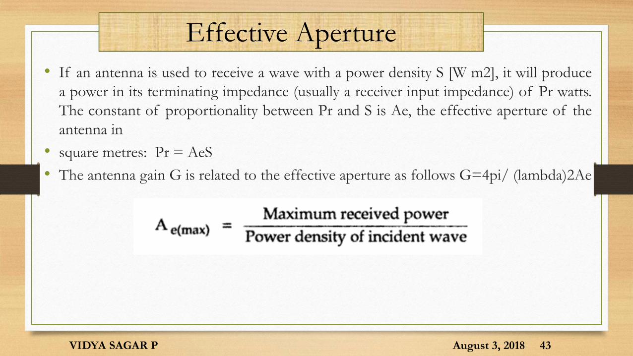
Effective Aperture
• If an antenna is used to receive a wave with a power density S [W m2], it will produce
a power in its terminating impedance (usually a receiver input impedance) of Pr watts.
The constant of proportionality between Pr and S is Ae, the effective aperture of the
antenna in
• square metres: Pr = AeS
• The antenna gain G is related to the effective aperture as follows G=4pi/ (lambda)2Ae
August 3, 2018VIDYA SAGAR P 43

Thank you………………
August 3, 2018VIDYA SAGAR P
44