celox for on-line process control in modern steelmaking · pdf filethe masters when it comes...
TRANSCRIPT
The masters when it comes to control techniques
Celox® for on-line process control in modern steelmaking
Ing. R. MaesProduct Application Manager
Heraeus Electro-NiteInternational N.V.
EN_brochure.indd 1 10/09/12 13:26

Celox® for on-line
proCess Control in modern steelmaking
EN_brochure.indd 2 10/09/12 13:26
1. ABOUT CELOX® 4
1.1 Measuring principle 4
1.2 Celox® and measuring system description 5
1.2.1 Celox® sensor 5
1.2.2 Celox® lance and accessories 7
1.2.3 Instrumentation 9
1.3 Formulae 9
1.4 Standard operating procedure 13
1.5 Sensor precision 14
1.6 Sample comparison 17
2. FAST MEASUREMENTS OF OXYGEN, CARBON AND ALUMINUM VIA THE CELOX® ROUTE 19
2.1 Oxygen determination 19
2.2 Carbon determination 20
2.3 Aluminium determination 21
3. CELOX® FOR PROCESS CONTROL IN MODERN STEELMAKING 23
3.1 Decarburization control in converters and EAF 23
3.1.1 Quick carbon determination (Quick-Tap practice) 23
3.1.2 Calculation of pre-deoxidation additions 24
3.1.3 Control of bottom stir efficiency 25
3.2 Decarburization control at degassing stations 25
3.3 Deoxidation control at the ladle treatment station 26
3.3.1 LCAK- steel grades (slab casters) 26
3.3.2 Mn-Si – killed steel grades (billet casters) 30
3.3.3 Successful continuous billet casting through oxygen control in mixed operations 34
3.4 Desulphurisation control 39
CElox® foR oN-lINE
PRoCEss CoNtRol IN ModERN stEElMAkINg
3
EN_brochure.indd 3 10/09/12 13:26
Celox® for on-line
proCess Control in modern steelmaking
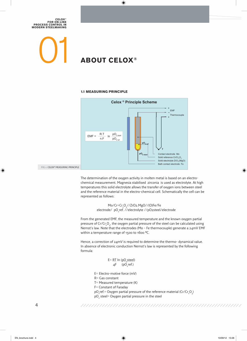
Fig.1: CELOX® MEASURING PRINCIPLE
ABoUt CElox®011.1 MEAsURINg PRINCIPlE
Thermocouple
Solid electrolyte ZrO (MgO)Solid reference Cr/Cr2O3
Contact electrode Mo
Bath contact electrode Fe
EMF
+
+-
T
pO2 steel
2
pO2 ref
EMF = lnR.T pO2 steel
pO2 refn.F
Celox ® Principle Scheme
The determination of the oxygen activity in molten metal is based on an electro-chemical measurement. Magnesia stabilised zirconia is used as electrolyte. At high temperatures this solid electrolyte allows the transfer of oxygen ions between steel and the reference material in the electro-chemical cell. Schematically the cell can be represented as follows:
Mo/Cr+Cr2O3//ZrO2.MgO//(O)Fe/Fe electrode/ pO2ref. //electrolyte //pO2steel/electrode
From the generated EMF, the measured temperature and the known oxygen partial pressure of Cr/Cr2O3, the oxygen partial pressure of the steel can be calculated using Nernst’s law. Note that the electrodes (Mo – Fe thermocouple) generate a 24mV EMF within a temperature range of 1500 to 1600 °C.
Hence, a correction of 24mV is required to determine the thermo- dynamical value. In absence of electronic conduction Nernst’s law is represented by the following formula:
E= RT ln (pO2steel) 4F (pO2ref.)
E= Electro-motive force (mV) R= Gas constant T= Measured temperature (K) F= Constant of Faraday pO2ref.= Oxygen partial pressure of the reference material (Cr/Cr2O3) pO2 steel= Oxygen partial pressure in the steel
4
EN_brochure.indd 4 10/09/12 13:26
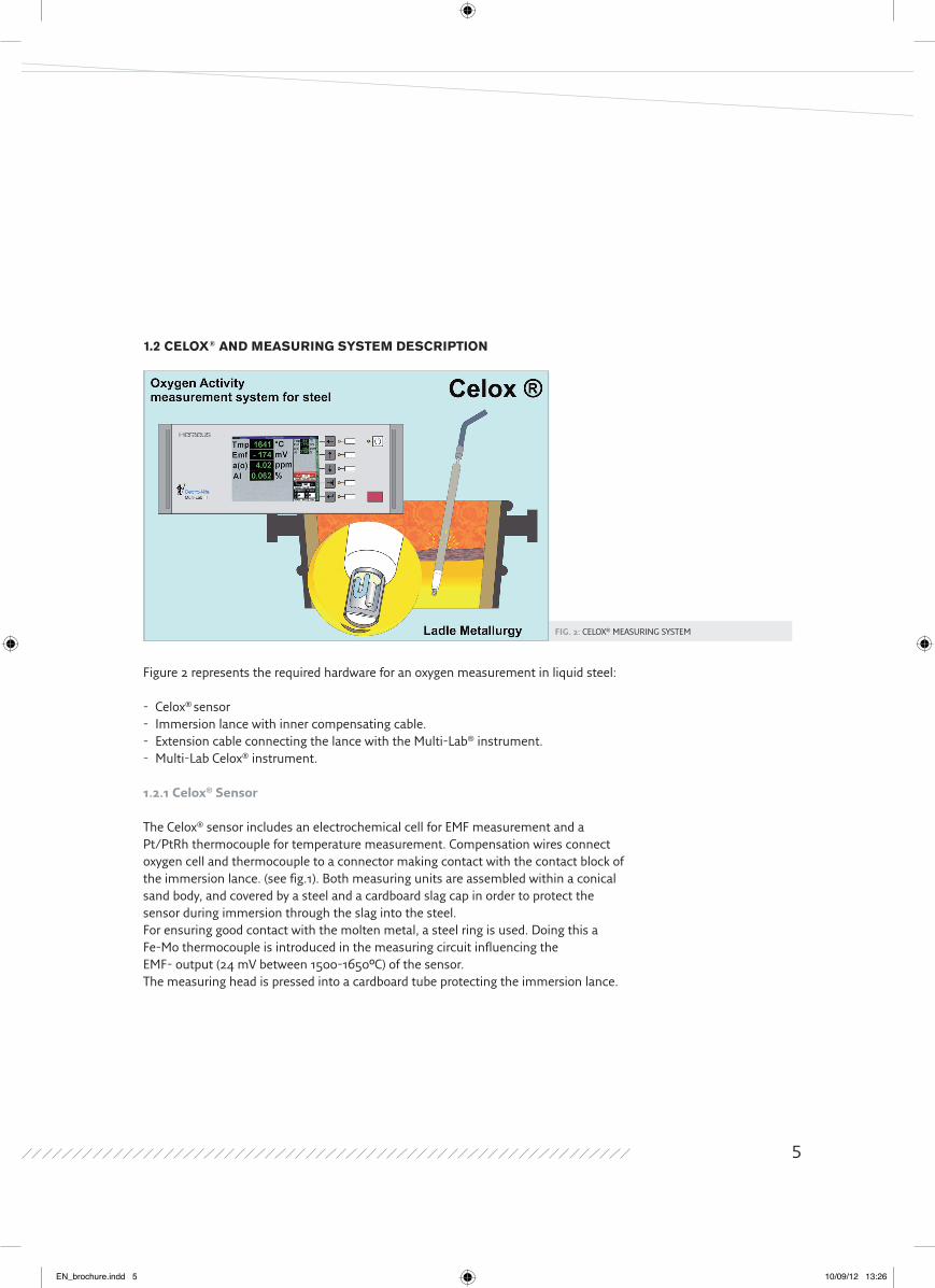
Fig. 2: CELOX® MEASURING SYSTEM
1.2 CElox® ANd MEAsURINg systEM dEsCRIPtIoN
Figure 2 represents the required hardware for an oxygen measurement in liquid steel:
- Celox® sensor- Immersion lance with inner compensating cable.- Extension cable connecting the lance with the Multi-Lab® instrument.- Multi-Lab Celox® instrument.
1.2.1 Celox® Sensor
The Celox® sensor includes an electrochemical cell for EMF measurement and a Pt/PtRh thermocouple for temperature measurement. Compensation wires connect oxygen cell and thermocouple to a connector making contact with the contact block of the immersion lance. (see fig.1). Both measuring units are assembled within a conical sand body, and covered by a steel and a cardboard slag cap in order to protect the sensor during immersion through the slag into the steel.For ensuring good contact with the molten metal, a steel ring is used. Doing this a Fe-Mo thermocouple is introduced in the measuring circuit influencing the EMF- output (24 mV between 1500-1650°C) of the sensor. The measuring head is pressed into a cardboard tube protecting the immersion lance.
5
EN_brochure.indd 5 10/09/12 13:26
Celox® for on-line
proCess Control in modern steelmaking
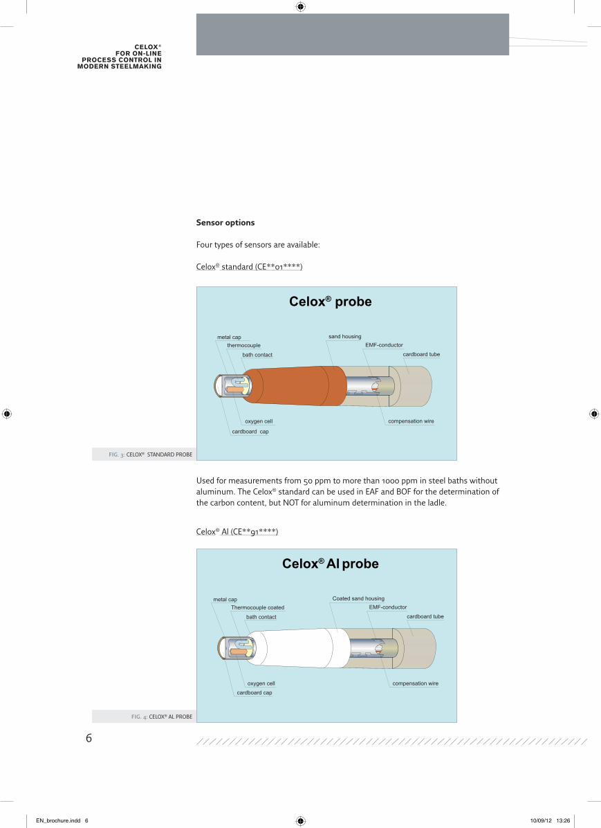
Fig. 3: CELOX® STANDARD PROBE
Fig. 4: CELOX® AL PROBE
Celox® probe
compensation wire
EMF-conductor
cardboard tube
metal cap
cardboard cap
oxygen cell
thermocouple
bath contact
sand housing
Celox® Al probe
compensation wire
EMF-conductor
cardboard tube
metal cap
cardboard cap
oxygen cell
Thermocouple coated
bath contact
Coated sand housing
Sensor options
Four types of sensors are available:
Celox® standard (CE**01****)
Used for measurements from 50 ppm to more than 1000 ppm in steel baths without aluminum. The Celox® standard can be used in EAF and BOF for the determination of the carbon content, but NOT for aluminum determination in the ladle.
Celox® Al (CE**91****)
6
EN_brochure.indd 6 10/09/12 13:26
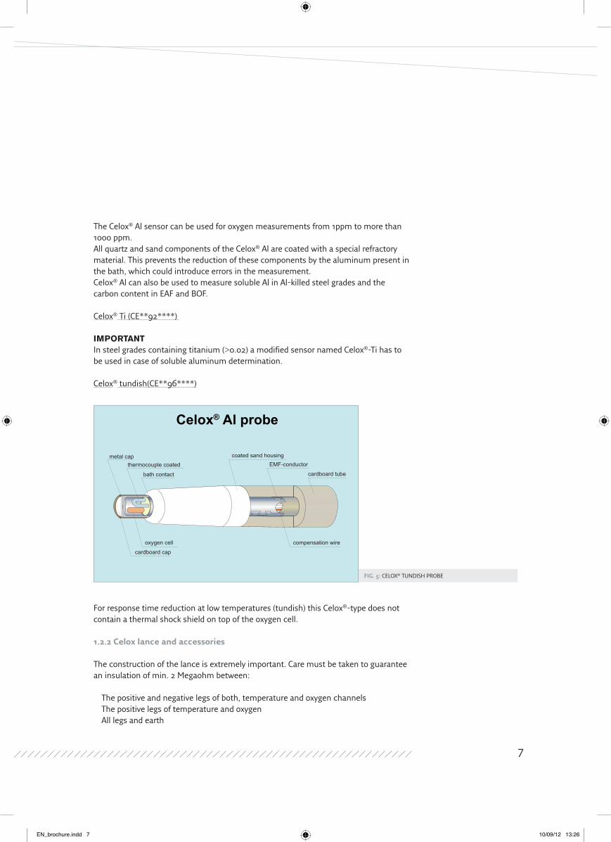
Fig. 5: CELOX® TUNDISH PROBE
The Celox® Al sensor can be used for oxygen measurements from 1ppm to more than 1000 ppm.All quartz and sand components of the Celox® Al are coated with a special refractory material. This prevents the reduction of these components by the aluminum present in the bath, which could introduce errors in the measurement.Celox® Al can also be used to measure soluble Al in Al-killed steel grades and the carbon content in EAF and BOF.
Celox® Ti (CE**92****)
IMPoRtANtIn steel grades containing titanium (>0.02) a modified sensor named Celox®-Ti has to be used in case of soluble aluminum determination.
Celox® tundish(CE**96****)
For response time reduction at low temperatures (tundish) this Celox®-type does not contain a thermal shock shield on top of the oxygen cell.
1.2.2 Celox lance and accessories
The construction of the lance is extremely important. Care must be taken to guarantee an insulation of min. 2 Megaohm between:
The positive and negative legs of both, temperature and oxygen channels The positive legs of temperature and oxygen All legs and earth
Celox® Al probe
compensation wire
EMF-conductor
cardboard tube
metal cap
oxygen cell
cardboard cap
thermocouple coated
bath contact
coated sand housing
7
EN_brochure.indd 7 10/09/12 13:26
Celox® for on-line
proCess Control in modern steelmaking
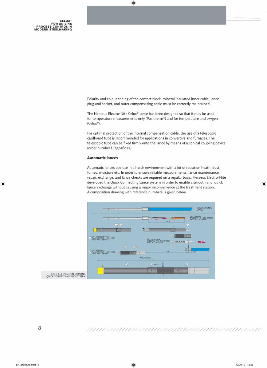
Fig.6: COMPOSITION DRAwINGQUICK CONNECTING LANCE SYSTEM
Polarity and colour coding of the contact block, mineral insulated inner cable, lance plug and socket, and outer compensating cable must be correctly maintained.
The Heraeus Electro-Nite Celox® lance has been designed so that it may be used for temperature measurements only (Positherm®) and for temperature and oxygen (Celox®).
For optimal protection of the internal compensation cable, the use of a telescopic cardboard tube is recommended for applications in converters and furnaces. The telescopic tube can be fixed firmly onto the lance by means of a conical coupling device (order number LC33016077)
Automatic lances
Automatic lances operate in a harsh environment with a lot of radiation heath, dust, fumes, moisture etc. In order to ensure reliable measurements, lance maintenance, repair, exchange, and lance checks are required on a regular basis. Heraeus Electro-Nite developed the Quick Connecting Lance system in order to enable a smooth and quick lance exchange without causing a major inconvenience at the treatment station.A composition drawing with reference numbers is given below.
CONVENTIONALLANCE
QCL detachable part/SSALESREF NO. : LC24016001PART NO. : 108.057.6- QCL contactblock
SALESREF NO. : LC24016005PART NO. : 118.002.6-
QCL fixed part/SSALESREF NO. : LC24016000PART NO. : 108.056.6-
Wire protection
QCL/S
QCL ConnectorSALESREF NO. : LC24016006PART NO. : 118.003.6-
8
7
1 2 3
1
2
3
4 5
5
4
6 6
7 9 8
max
.30,
5
G 3
/4”
min.16~381
330 +5 0
8
EN_brochure.indd 8 10/09/12 13:26
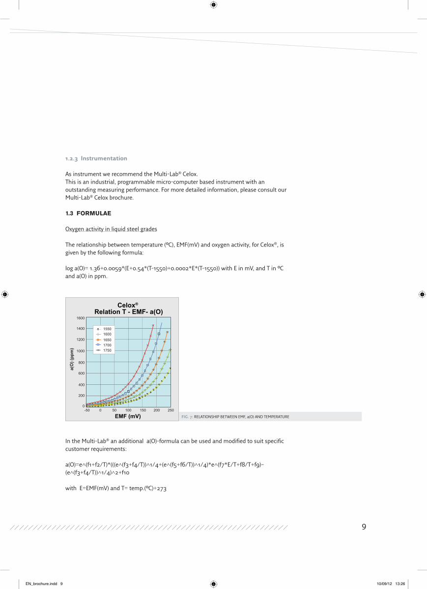
Fig. 7: RELATIONSHIP BETwEEN EMF, a(O) AND TEMPERATURE
1.2.3 instrumentation
As instrument we recommend the Multi-Lab® Celox.This is an industrial, programmable micro-computer based instrument with an outstanding measuring performance. For more detailed information, please consult our Multi-Lab® Celox brochure.
1.3 foRMUlAE
Oxygen activity in liquid steel grades
The relationship between temperature (°C), EMF(mV) and oxygen activity, for Celox®, is given by the following formula:
log a(O)= 1.36+0.0059*(E+0.54*(T-1550)+0.0002*E*(T-1550)) with E in mV, and T in °C and a(O) in ppm.
Celox® Relation T - EMF- a(O)
EMF (mV)
a(O
) (pp
m)
15010050-500
200
400
600
800
1000
1200
1400
1600
0 200 250
15501600165017001750
In the Multi-Lab® an additional a(O)-formula can be used and modified to suit specific customer requirements:
a(O)=e^(f1+f2/T)*(((e^(f3+f4/T))^1/4+(e^(f5+f6/T))^1/4)*e^(f7*E/T+f8/T+f9)–(e^(f3+f4/T))^1/4)^2+f10
with E=EMF(mV) and T= temp.(°C)+273
9
EN_brochure.indd 9 10/09/12 13:26
Celox® for on-line
proCess Control in modern steelmaking
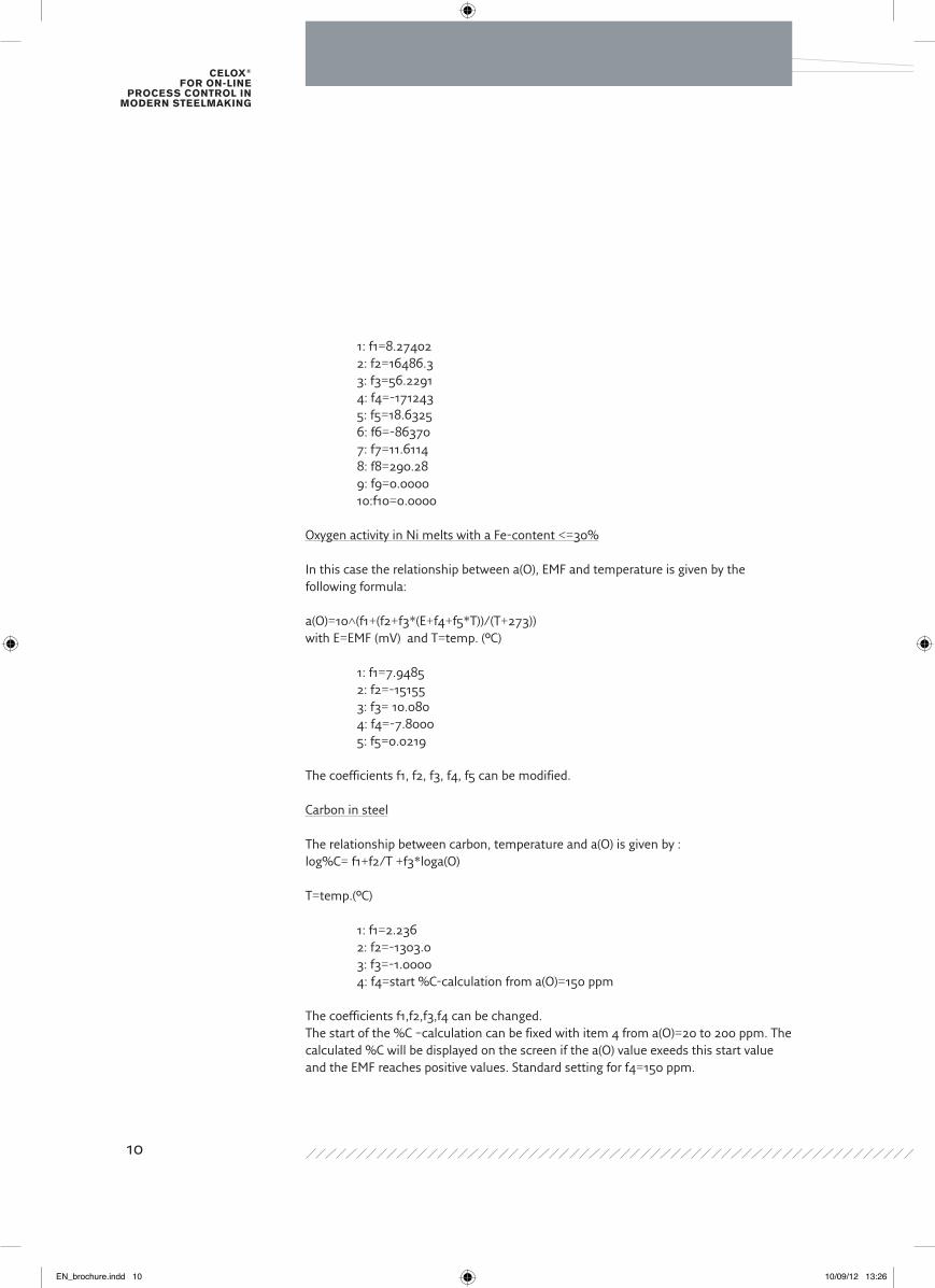
1: f1=8.27402 2: f2=16486.3 3: f3=56.2291 4: f4=-171243 5: f5=18.6325 6: f6=-86370 7: f7=11.6114 8: f8=290.28 9: f9=0.0000 10:f10=0.0000
Oxygen activity in Ni melts with a Fe-content <=30%
In this case the relationship between a(O), EMF and temperature is given by the following formula:
a(O)=10^(f1+(f2+f3*(E+f4+f5*T))/(T+273)) with E=EMF (mV) and T=temp. (°C)
1: f1=7.9485 2: f2=-15155 3: f3= 10.080 4: f4=-7.8000 5: f5=0.0219
The coefficients f1, f2, f3, f4, f5 can be modified.
Carbon in steel
The relationship between carbon, temperature and a(O) is given by :log%C= f1+f2/T +f3*loga(O)
T=temp.(°C)
1: f1=2.236 2: f2=-1303.0 3: f3=-1.0000 4: f4=start %C-calculation from a(O)=150 ppm
The coefficients f1,f2,f3,f4 can be changed.The start of the %C –calculation can be fixed with item 4 from a(O)=20 to 200 ppm. The calculated %C will be displayed on the screen if the a(O) value exeeds this start value and the EMF reaches positive values. Standard setting for f4=150 ppm.
10
EN_brochure.indd 10 10/09/12 13:26
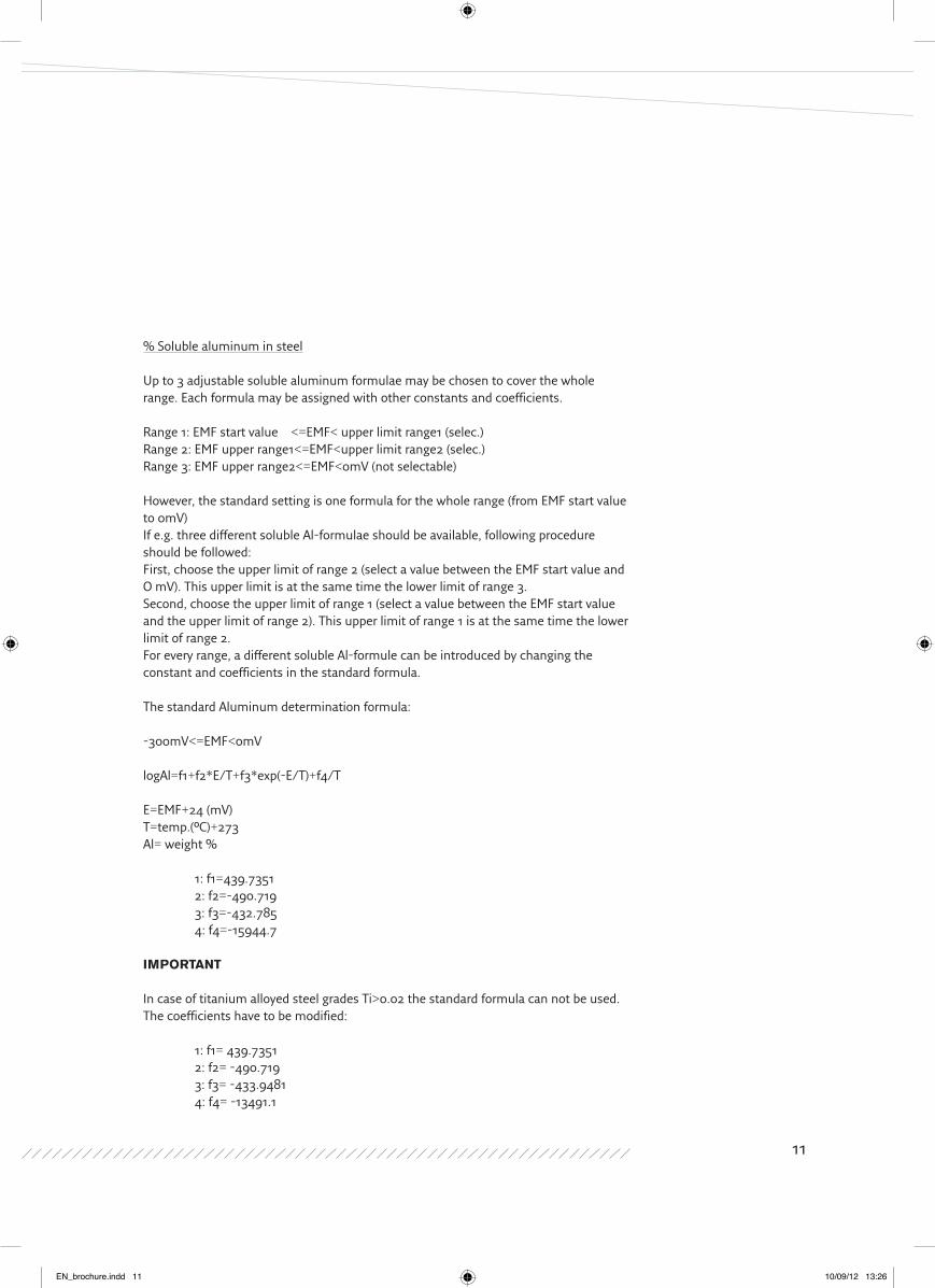
% Soluble aluminum in steel
Up to 3 adjustable soluble aluminum formulae may be chosen to cover the whole range. Each formula may be assigned with other constants and coefficients.
Range 1: EMF start value <=EMF< upper limit range1 (selec.)Range 2: EMF upper range1<=EMF<upper limit range2 (selec.)Range 3: EMF upper range2<=EMF<0mV (not selectable)
However, the standard setting is one formula for the whole range (from EMF start value to 0mV) If e.g. three different soluble Al-formulae should be available, following procedure should be followed:First, choose the upper limit of range 2 (select a value between the EMF start value and O mV). This upper limit is at the same time the lower limit of range 3.Second, choose the upper limit of range 1 (select a value between the EMF start value and the upper limit of range 2). This upper limit of range 1 is at the same time the lower limit of range 2.For every range, a different soluble Al-formule can be introduced by changing the constant and coefficients in the standard formula.
The standard Aluminum determination formula:
-300mV<=EMF<0mV
logAl=f1+f2*E/T+f3*exp(-E/T)+f4/T
E=EMF+24 (mV)T=temp.(°C)+273 Al= weight %
1: f1=439.7351 2: f2=-490.719 3: f3=-432.785 4: f4=-15944.7
IMPoRtANt
In case of titanium alloyed steel grades Ti>0.02 the standard formula can not be used. The coefficients have to be modified:
1: f1= 439.7351 2: f2= -490.719 3: f3= -433.9481 4: f4= -13491.1
11
EN_brochure.indd 11 10/09/12 13:26
Celox® for on-line
proCess Control in modern steelmaking
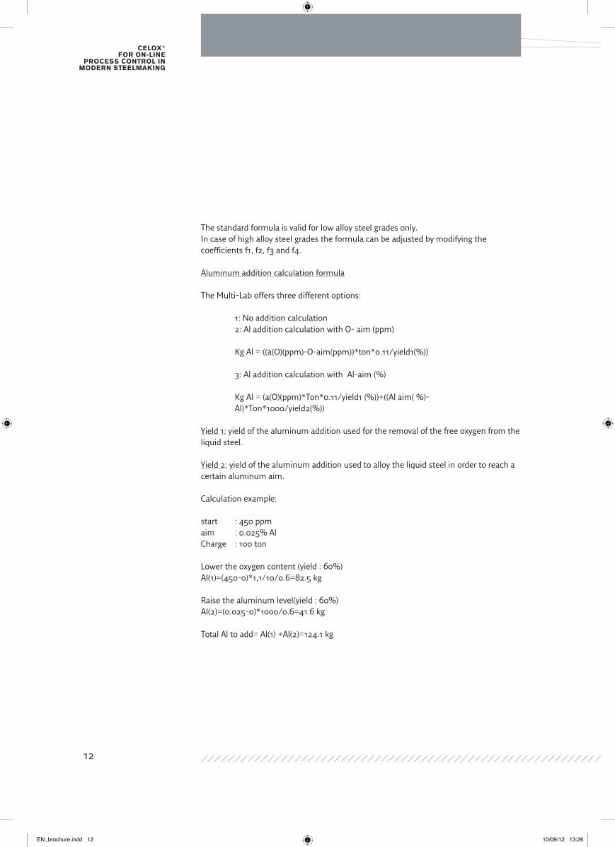
The standard formula is valid for low alloy steel grades only.In case of high alloy steel grades the formula can be adjusted by modifying the coefficients f1, f2, f3 and f4.
Aluminum addition calculation formula
The Multi-Lab offers three different options:
1: No addition calculation 2: Al addition calculation with O- aim (ppm)
Kg Al = ((a(O)(ppm)-O-aim(ppm))*ton*0.11/yield1(%)) 3: Al addition calculation with Al-aim (%)
Kg Al = (a(O)(ppm)*Ton*0.11/yield1 (%))+((Al aim( %)- Al)*Ton*1000/yield2(%))
Yield 1: yield of the aluminum addition used for the removal of the free oxygen from the liquid steel.
Yield 2: yield of the aluminum addition used to alloy the liquid steel in order to reach a certain aluminum aim.
Calculation example:
start : 450 ppmaim : 0.025% AlCharge : 100 ton
Lower the oxygen content (yield : 60%)Al(1)=(450-0)*1,1/10/0.6=82.5 kg
Raise the aluminum level(yield : 60%)Al(2)=(0.025-0)*1000/0.6=41.6 kg
Total Al to add= Al(1) +Al(2)=124.1 kg
12
EN_brochure.indd 12 10/09/12 13:26
1.4 stANdARd oPERAtINg PRoCEdURE
In order to obtain accurate results, the following precautions should be taken:
•Probesmustbekeptdryandhandledcarefully.
•Thelanceandextensioncablemustbekeptdryandinagoodcondition.Manymeasurement errors are the result of lance or cable problems.
•Theprobemustbewellfixedontothelanceandimmersedquicklythroughtheslaginto the liquid metal to a depth of 30 to 40 cm, away from the ladle or furnace lining and from the influence of the slag.
•Gasstirring(Ar,N2,…)hastobestoppedduringCelox® measurement. The recommended waiting time after stirring is 60 seconds. In case waiting time is not respected, wrong oxygen levels may be measured.
•Theelectricpowerofthefurnacehastobeswitchedoffduringmeasurement. Additions should be thoroughly mixed before measurement, typically for about 3-4
minutes.
•Slagcrustsshouldbekeptthin,ortheslagbefluxedtopreventmechanicaldamageto the probe on immersion.
•Temperaturerangefrom1570°Cupto1740°C. Use Celox® tundish in case temperature is lower then 1570°C.
13
EN_brochure.indd 13 10/09/12 13:26

Celox® for on-line
proCess Control in modern steelmaking
Fig. 8: TYPICAL TEMPERATURE AND OXYGEN TRACE
1.5 sENsoR PRECIsIoN
The measuring traces of both temperature, and oxygen signals are characterized by stable plateaus and short response times. The recommended immersion time is approximately 8 to 10 seconds.
The accuracy of the thermocouple wire is 0 to +4 °C at 1554 °C.
Oxygen cells used for the production of Celox are submitted to the most rigourous quality control procedures.All critical components such as the solid electrolyte, reference material etc. are all manufactured in house by Heraeus Electro-Nite. In this way, quality is 100% assured throughout the entire sensor production process.
27-1-99 11:50 HT-NO. : 32 Place : 1 No: 340Type : S
300 1650270 1640240 1630210 1620180 1610150 1600120 1590
90 158060 157030 1560
0 15500.0 2.0 4.0 6.0 8.0 10.0 t (s)
EM
F
: [m
V]
TE
MP
:
∞C
TEMP:Tvar:EMF:Evar:a(O):C:
1598.2 ∞C -1.3 ∞C 216.2 mV -1.9 mV 633.1 ppm 0.041 %
Multi-labCelox
14
EN_brochure.indd 14 10/09/12 13:26
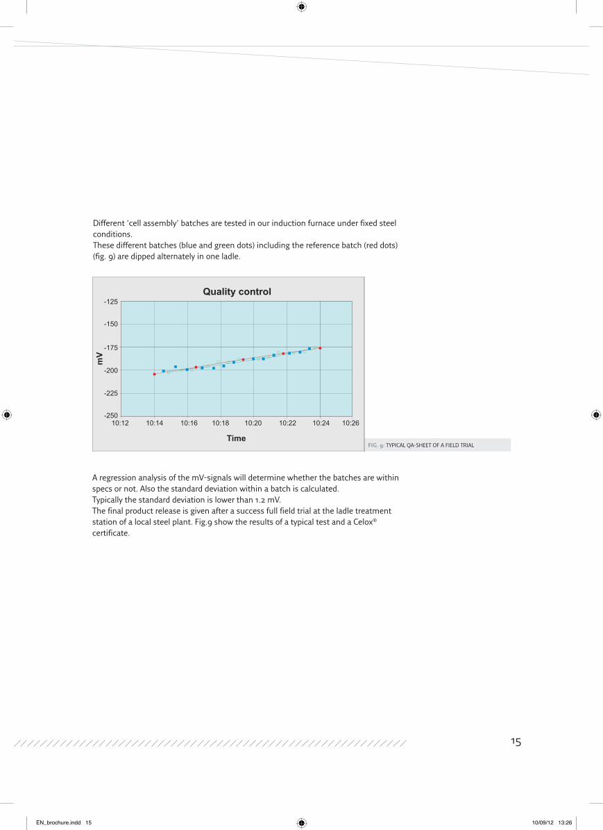
Fig. 9: TYPICAL QA-SHEET OF A FIELD TRIAL
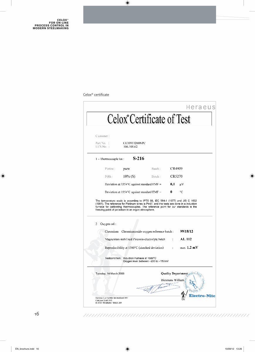
A regression analysis of the mV-signals will determine whether the batches are within specs or not. Also the standard deviation within a batch is calculated. Typically the standard deviation is lower than 1.2 mV.The final product release is given after a success full field trial at the ladle treatment station of a local steel plant. Fig.9 show the results of a typical test and a Celox® certificate.
Time
mV
10:12-250
-225
-200
-175
-150
-125
10:14 10:16 10:18 10:20 10:22 10:24 10:26
Quality control
Different ‘cell assembly’ batches are tested in our induction furnace under fixed steel conditions.These different batches (blue and green dots) including the reference batch (red dots) (fig. 9) are dipped alternately in one ladle.
15
EN_brochure.indd 15 10/09/12 13:26
Celox® for on-line
proCess Control in modern steelmaking
Celox® certificate
16
EN_brochure.indd 16 10/09/12 13:26
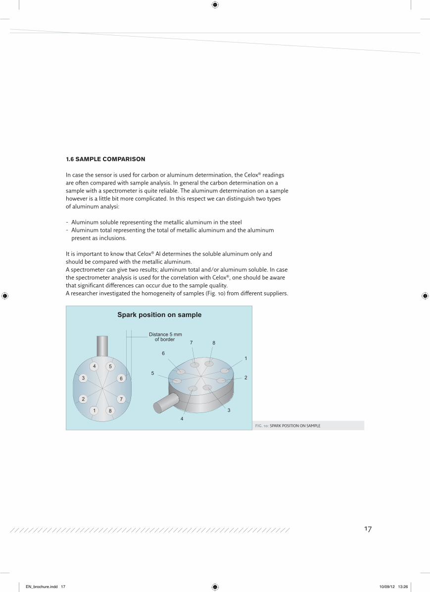
Fig. 10: SPARK POSITION ON SAMPLE
1.6 sAMPlE CoMPARIsoN
In case the sensor is used for carbon or aluminum determination, the Celox® readings are often compared with sample analysis. In general the carbon determination on a sample with a spectrometer is quite reliable. The aluminum determination on a sample however is a little bit more complicated. In this respect we can distinguish two typesof aluminum analysi:
- Aluminum soluble representing the metallic aluminum in the steel- Aluminum total representing the total of metallic aluminum and the aluminum
present as inclusions. It is important to know that Celox® Al determines the soluble aluminum only and should be compared with the metallic aluminum.A spectrometer can give two results; aluminum total and/or aluminum soluble. In case the spectrometer analysis is used for the correlation with Celox®, one should be aware that significant differences can occur due to the sample quality. A researcher investigated the homogeneity of samples (Fig. 10) from different suppliers.
Spark position on sample
6
7 8
1
2
3
4
54 5
6
7
8
3
2
1
Distance 5 mmof border
17
EN_brochure.indd 17 10/09/12 13:26
Celox® for on-line
proCess Control in modern steelmaking
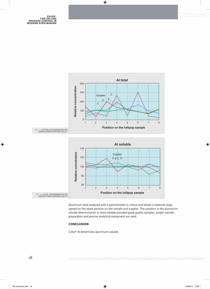
Fig. 11: Al-TOTAL DETERMINATION ON SAMPLES FROM SUPPLIER A,B,C,D.
Fig. 12: Al-SOL. DETERMINATION ON SAMPLES FROM SUPPLIER A,B,C,D
Aluminum total analysed with a spectrometer is critical and shows a relatively large spread on the spark position on the sample and supplier. The variation in the aluminum soluble determination is more reliable provided good quality samples, proper sample preparation and precise analytical equipment are used.
CoNClUsIoN Celox® Al determines aluminum soluble.
Al totalR
elat
ive
conc
entr
atio
n
Position on the lollipop sample
400
300
200
100
01 2 3 4 5 6 7 8
Supplier
A B
C
D
Al soluble
Rel
ativ
e co
ncet
ratio
n
Position on the lollipop sample
140
120
100
80
601 2 3 4 5 6 7 8
SupplierA B C D
18
EN_brochure.indd 18 10/09/12 13:26
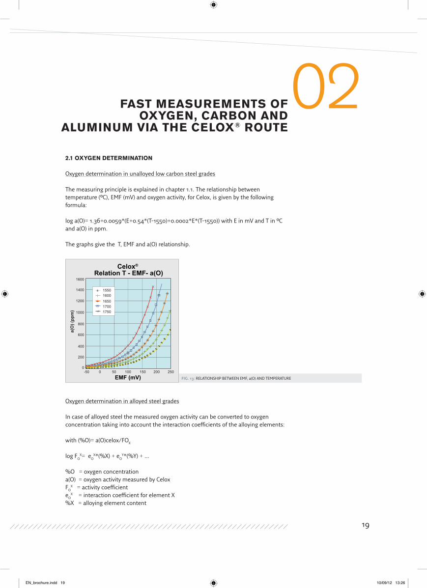
Fig. 13: RELATIONSHIP BETwEEN EMF, a(O) AND TEMPERATURE
2.1 oxygEN dEtERMINAtIoN
Oxygen determination in unalloyed low carbon steel grades
The measuring principle is explained in chapter 1.1. The relationship between temperature (°C), EMF (mV) and oxygen activity, for Celox, is given by the following formula:
log a(O)= 1.36+0.0059*(E+0.54*(T-1550)+0.0002*E*(T-1550)) with E in mV and T in °C and a(O) in ppm.
The graphs give the T, EMF and a(O) relationship.
fAst MEAsUREMENts of oxygEN, CARBoN ANd
AlUMINUM VIA tHE CElox® RoUtE
02
Oxygen determination in alloyed steel grades
In case of alloyed steel the measured oxygen activity can be converted to oxygen concentration taking into account the interaction coefficients of the alloying elements:
with (%O)= a(O)celox/FOX
log FOX= eO
X*(%X) + eOY*(%Y)+…
%O = oxygen concentrationa(O) = oxygen activity measured by CeloxFO
X = activity coefficient eO
X = interaction coefficient for element X%X = alloying element content
Celox® Relation T - EMF- a(O)
EMF (mV)
a(O
) (pp
m)
15010050-500
200
400
600
800
1000
1200
1400
1600
0 200 250
15501600165017001750
19
EN_brochure.indd 19 10/09/12 13:26
Celox® for on-line
proCess Control in modern steelmaking
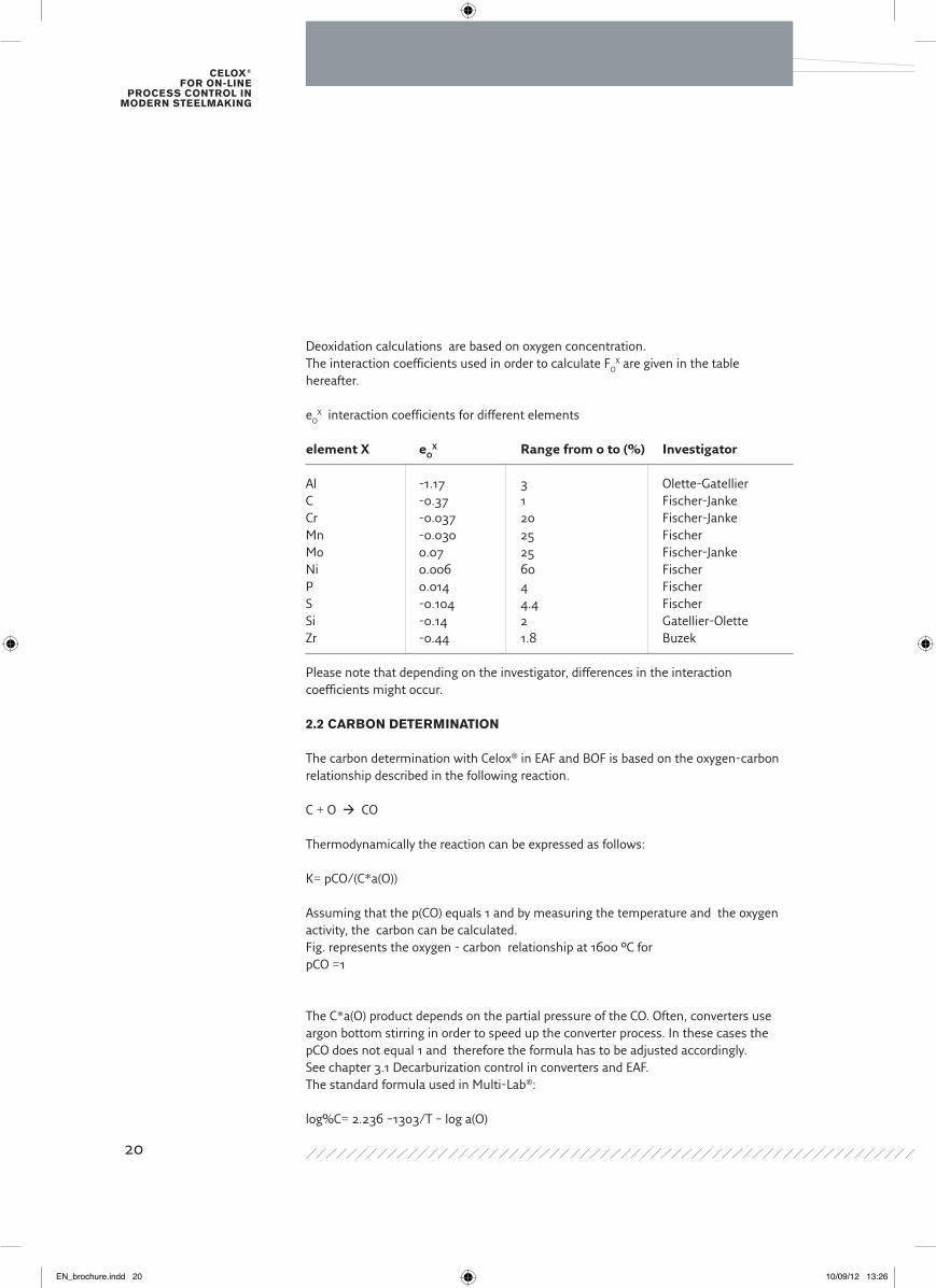
Deoxidation calculations are based on oxygen concentration.The interaction coefficients used in order to calculate FO
X are given in the table hereafter. eO
X interaction coefficients for different elements
element X eOX Range from 0 to (%) investigator
Al -1.17 3 Olette-GatellierC -0.37 1 Fischer-JankeCr -0.037 20 Fischer-JankeMn -0.030 25 FischerMo 0.07 25 Fischer-JankeNi 0.006 60 FischerP 0.014 4 FischerS -0.104 4.4 FischerSi -0.14 2 Gatellier-OletteZr -0.44 1.8 Buzek
Please note that depending on the investigator, differences in the interaction coefficients might occur.
2.2 CARBoN dEtERMINAtIoN
The carbon determination with Celox® in EAF and BOF is based on the oxygen-carbon relationship described in the following reaction.
C + O CO
Thermodynamically the reaction can be expressed as follows:
K= pCO/(C*a(O))
Assuming that the p(CO) equals 1 and by measuring the temperature and the oxygen activity, the carbon can be calculated.Fig. represents the oxygen - carbon relationship at 1600 °C for pCO =1
The C*a(O) product depends on the partial pressure of the CO. Often, converters use argon bottom stirring in order to speed up the converter process. In these cases the pCO does not equal 1 and therefore the formula has to be adjusted accordingly.See chapter 3.1 Decarburization control in converters and EAF.The standard formula used in Multi-Lab®:
log%C= 2.236 –1303/T – log a(O)
20
EN_brochure.indd 20 10/09/12 13:26
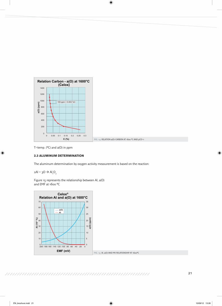
Fig. 14: RELATION a(O)-CARBON AT 1600 °C AND pCO=1
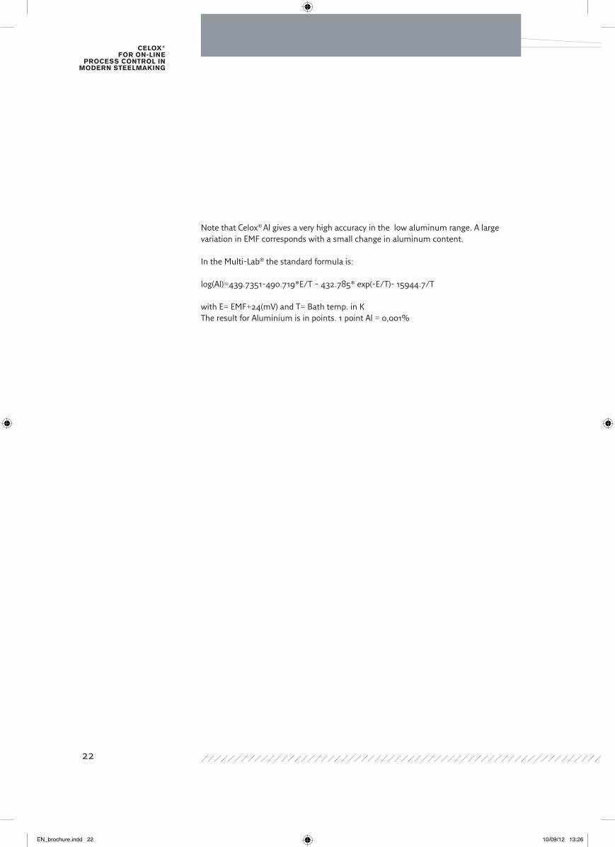
Fig. 15: Al, a(O) AND MV RELATIONSHIP AT 1600°C
T=temp. (°C) and a(O) in ppm
2.3 AlUMINUM dEtERMINAtIoN
The aluminum determination by oxygen activity measurement is based on the reaction:
2Al + 3O Al2O3
Figure 15 represents the relationship between Al, a(O) and EMF at 1600 °C
C (%)
a(O
) (pp
m)
0.10.050 0.15 0.2 0.25 0.30
200
400
600
800
1000 100 ppm = 0.003 %C
1200
1400
Relation Carbon - a(O) at 1600°C (Celox)
Celox® Relation Al and a(O) at 1600°C
EMF (mV)
Al (
10-3 %
)
a(O
) (pp
m)
0 0
10 5
20 10
30 15
40 20
50 25
60 30
70 35
0-20-40-60-80-100-120-140-160-180-200
a(O)Al
21
EN_brochure.indd 21 10/09/12 13:26
Celox® for on-line
proCess Control in modern steelmaking
Note that Celox® Al gives a very high accuracy in the low aluminum range. A large variation in EMF corresponds with a small change in aluminum content.
In the Multi-Lab® the standard formula is:
log(Al)=439.7351-490.719*E/T – 432.785* exp(-E/T)- 15944.7/T
with E= EMF+24(mV) and T= Bath temp. in KThe result for Aluminium is in points. 1 point Al = 0,001%
22
EN_brochure.indd 22 10/09/12 13:26
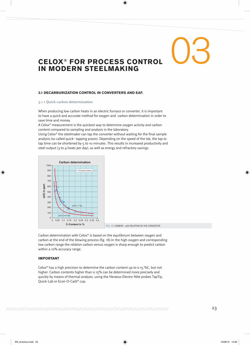
Fig. 16: CARBON - a(O) RELATION IN THE CONVERTER
CElox® foR PRoCEss CoNtRol IN ModERN stEElMAkINg
033.1 dECARBURIzAtIoN CoNtRol IN CoNVERtERs ANd EAf.
3.1.1 Quick carbon determination
when producing low carbon heats in an electric furnace or converter, it is important to have a quick and accurate method for oxygen and carbon determination in order to save time and money.A Celox® measurement is the quickest way to determine oxygen activity and carbon content compared to sampling and analysis in the laboratory.Using Celox® the steelmaker can tap the converter without waiting for the final sample analysis (so called quick- tapping praxis). Depending on the speed of the lab, the tap to tap time can be shortened by 5 to 10 minutes. This results in increased productivity and steel output (3 to 4 heats per day), as well as energy and refractory savings.
Carbon determination with Celox® is based on the equilibrium between oxygen and carbon at the end of the blowing process (fig. 16).In the high oxygen and corresponding low carbon range the relation carbon versus oxygen is sharp enough to predict carbon within a 10% accuracy range.
IMPoRtANt
Celox® has a high precision to determine the carbon content up to 0.15 %C, but not higher. Carbon contents higher than 0.15% can be determined more precisely and quickly by means of thermal analysis, using the Heraeus Electro-Nite probes TapTip, Quick-Lab or Econ-O-Carb® cup.
C-Content in %
a(O
) in
ppm
=Practical Values
1000
900
800
700
600
500
400
300
200
100
00 0.05 0.1 0.15 0.2 0.25 0.3 0.35 0.4
p(CO) =1 bar
p(CO) =0.5 bar
Carbon determination
23
EN_brochure.indd 23 10/09/12 13:26
Celox® for on-line
proCess Control in modern steelmaking
Carbon formula
The relationship between carbon, temperature and a(O) is given by :
Log%C= f1+f2/T +f3*loga(O)
T=temp.(°C)
1: f1=2.236 2: f2=-1303.0 3: f3=-1.0000 4: f4=start %C-calculation from 150 ppm
The coefficients f1,f2,f3,f4 can be changed.The start of the %C –calculation can be fixed with item 4 from a(O)=20 to 200 ppm. The calculated %C will be displayed on the screen if the a(O) value exeeds this start value and the EMF reaches positive values. Standard setting for a(O)=150 ppm.
3.1.2 Calculation of pre-deoxidation additions
An oxygen measurement in the EAF or converter is also used to calculate the deoxidation additions to be added to the tapping stream or to the transfer ladle.Knowing the oxygen level is especially beneficial for low carbon steels having relatively high and fluctuating oxygen levels. A carbon content of 0.02% for example corresponds to an oxygen level between 600 and 1000 ppm depending on the blowing practice.
Aluminium addition calculation formula
The Multi-Lab® offers three different options:
1: No addition calculation 2: Al addition calculation with O- aim (ppm)
Kg Al= ((a(O)(ppm)-O-aim(ppm))*ton*0.11/yield1(%)) 3: Al addition calculation with Al-aim (%)
Kg Al= (a(O)(ppm)*Ton*0.11/yield1 (%))+((Al aim( %)- Al)*Ton*1000/yield2(%))
Yield 1: the yield of the aluminum addition used for the removal of the free oxygen from the liquid steel.
Yield 2: the yield of the aluminum addition used to alloy the liquid steel in order to reach a certain aluminum aim.
24
EN_brochure.indd 24 10/09/12 13:26
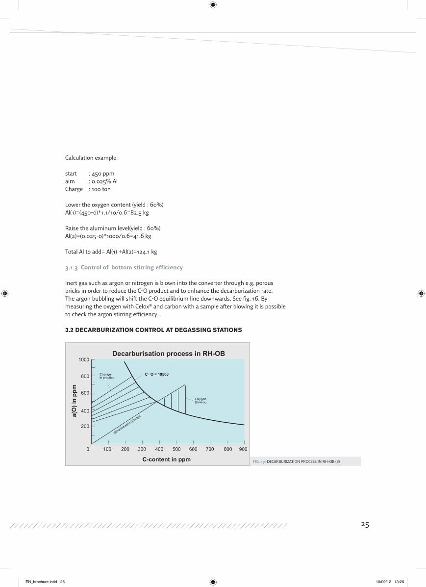
Fig. 17: DECARBURIZATION PROCESS IN RH-OB (8)
Calculation example:
start : 450 ppmaim : 0.025% AlCharge : 100 ton
Lower the oxygen content (yield : 60%)Al(1)=(450-0)*1,1/10/0.6=82.5 kg
Raise the aluminum level(yield : 60%)Al(2)=(0.025-0)*1000/0.6=41.6 kg
Total Al to add= Al(1) +Al(2)=124.1 kg
3.1.3 Control of bottom stirring efficiency
Inert gas such as argon or nitrogen is blown into the converter through e.g. porous bricks in order to reduce the C-O product and to enhance the decarburization rate. The argon bubbling will shift the C-O equilibrium line downwards. See fig. 16. By measuring the oxygen with Celox® and carbon with a sample after blowing it is possible to check the argon stirring efficiency.
3.2 dECARBURIzAtIoN CoNtRol At dEgAssINg stAtIoNs
C-content in ppm
a(O
) in
ppm
1000
OxygenBlowing
Changein practice
C O = 19500
Stöchiometric Change
800
600
400
200
0 100 200 300 400 500 600 700 800 900
Decarburisation process in RH-OB
25
EN_brochure.indd 25 10/09/12 13:26
Celox® for on-line
proCess Control in modern steelmaking
The graphic describes the decarburization process of ULC – steel grades in a RH-OB. In this example the carbon content before treatment is 380 ppm. In theory (stoechiometric change) the decarburization process will follow the dotted line. In reality however the decarburization process will be infuenced by external oxygen coming from the slag. At the end of the process a carbon content of 15 ppm and an oxygen content of around 250 ppm is obtained. Extra oxygen blowing is required in case the carbon content before degassing is higher than 380 ppm otherwise the decarburization process will be too long or the carbon target will not be reached.In case the carbon content is lower than 380 ppm, the decarburization will be faster but the end oxygen will be higher and more aluminum will be required to kill the steel.RH- degassers require an even tighter control of oxygen (400 to 500ppm) and carbon (200 to 250 ppm). If no oxygen is blown in the steel during the RH treatment, the final carbon content will depend on the oxygen and carbon level before vacuum. The target is to obtain the lowest carbon content (<20 ppm) and a reproducible low oxygen content (250 ppm) at the end of the treatment.The example above shows clearly that a close control of oxygen and carbon is required for efficient and low cost decarburization. 3.3 dEoxIdAtIoN CoNtRol At tHE lAdlE tREAtMENt stAtIoN
One of the main purposes of ladle metallurgy is to adjust the chemical analysis of the steel in order to have a composition appropriate for the continuous caster.The deoxidation praxis for billet and slab casters must be distinguished, because of the different steel grades.
3.3.1 LCAK- steel grades (slab casters)
The aluminum aim for this type of steel is normally around 0.040%.Because of the equilibrium between oxygen and aluminum, Celox® is not only suitable to measure the oxygen activity but also the soluble aluminum content. This method has a relative accuracy of 10%.
26
EN_brochure.indd 26 10/09/12 13:26
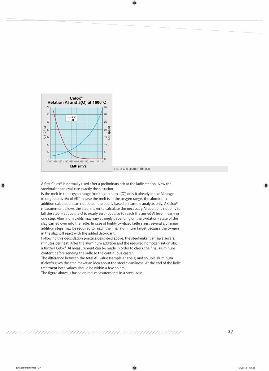
Fig. 18: Al-O RELATION FOR LCAK
A first Celox® is normally used after a preliminary stir at the ladle station. Now the steelmaker can evaluate exactly the situation.Is the melt in the oxygen range (100 to 200 ppm a(O)) or is it already in the Al range (0.005 to 0.020% of Al)? In case the melt is in the oxygen range, the aluminum addition calculation can not be done properly based on sample analysis only. A Celox® measurement allows the steel maker to calculate the necessary Al additions not only to kill the steel (reduce the O to nearly zero) but also to reach the aimed Al level, nearly in one step. Aluminum yields may vary strongly depending on the oxidation- state of the slag carried over into the ladle. In case of highly oxydized ladle slags, several aluminum addition steps may be required to reach the final aluminum target because the oxygen in the slag will react with the added deoxidant. Following this deoxidation practica described above, the steelmaker can save several minutes per heat. After the aluminum addition and the required homogenisation stir, a further Celox®-Al measurement can be made in order to check the final aluminum content before sending the ladle to the continuous caster.The difference between the total Al- value (sample analysis) and soluble aluminum (Celox®) gives the steelmaker an idea about the steel cleanliness. At the end of the ladle treatment both values should be within a few points. The figure above is based on real measurements in a steel ladle.
Celox® Relation Al and a(O) at 1600°C
EMF (mV)
Al (
10-3 %
)
a(O
) (pp
m)
0 0
10 5
20 10
30 15
40 20
50 25
60 30
70 35
0-20-40-60-80-100-120-140-160-180-200
a(O)Al
27
EN_brochure.indd 27 10/09/12 13:26
Celox® for on-line
proCess Control in modern steelmaking
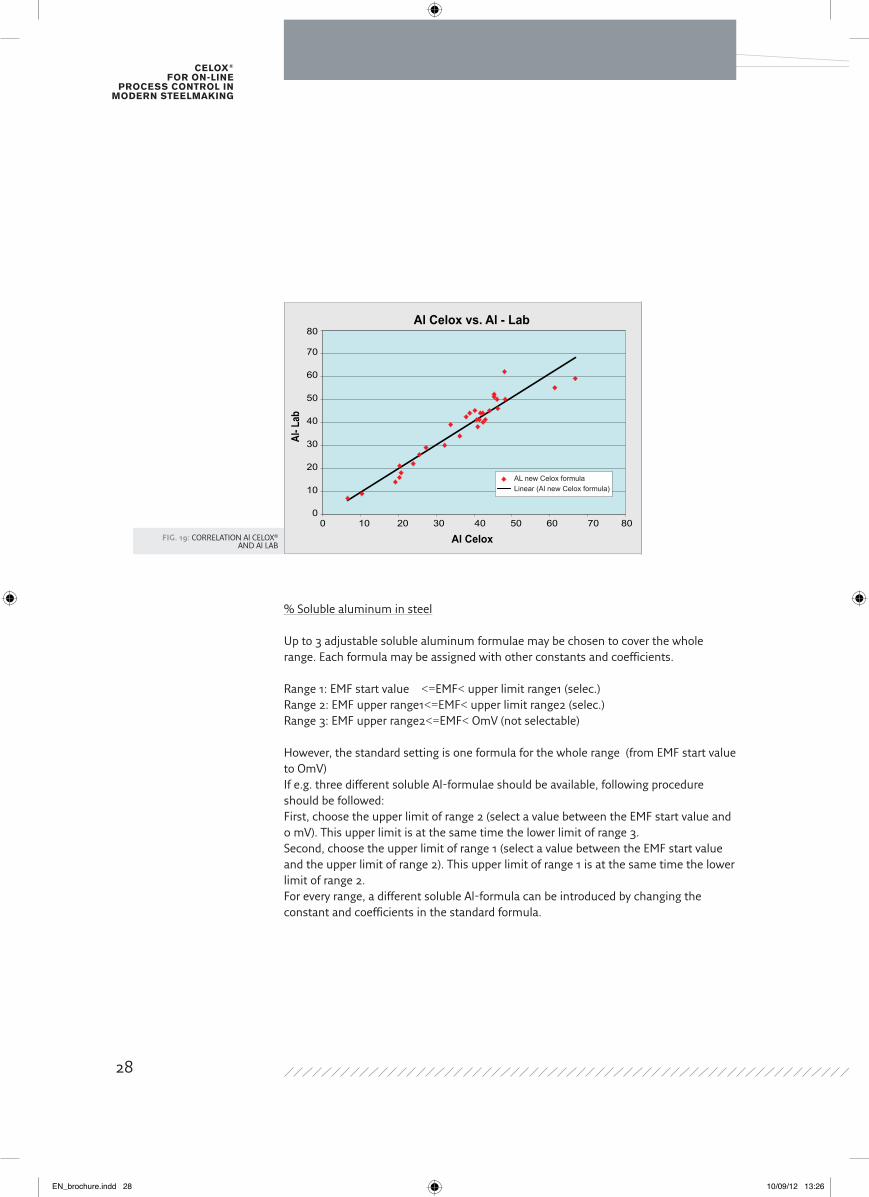
Fig. 19: CORRELATION Al CELOX® AND Al LAB
% Soluble aluminum in steel
Up to 3 adjustable soluble aluminum formulae may be chosen to cover the whole range. Each formula may be assigned with other constants and coefficients.
Range 1: EMF start value <=EMF< upper limit range1 (selec.)Range 2: EMF upper range1<=EMF< upper limit range2 (selec.)Range 3: EMF upper range2<=EMF< OmV (not selectable)
However, the standard setting is one formula for the whole range (from EMF start value to OmV) If e.g. three different soluble Al-formulae should be available, following procedure should be followed:First, choose the upper limit of range 2 (select a value between the EMF start value and 0 mV). This upper limit is at the same time the lower limit of range 3.Second, choose the upper limit of range 1 (select a value between the EMF start value and the upper limit of range 2). This upper limit of range 1 is at the same time the lower limit of range 2.For every range, a different soluble Al-formula can be introduced by changing the constant and coefficients in the standard formula.
Al Celox vs. Al - Lab
Al Celox
00 10 20 30 40 50 60 70 80
10
20
30
40
50
60
70
80
Al- L
ab
AL new Celox formulaLinear (Al new Celox formula)
28
EN_brochure.indd 28 10/09/12 13:26
The standard Aluminum determination formula:
-300mV<=EMF<OmV
logAl=f1+f2*E/T+f3*exp(-E/T)+f4/T
E=EMF+24 (mV)T=temp.(°C)+273 Al= weight %
1: f1=439.7351 2: f2=-490.719 3: f3=-432.785 4: f4=-15944.7
IMPoRtANt
In case of titanium alloyed steel grades Ti>0.02% the standard formula can not be used. The coefficients have to be modified:
1: f1= 439.7351 2: f2= -490.719 3: f3= -433.9481 4: f4= -13491.1
The standard formula is valid for low alloy steel grades only.In case of high alloy steel grades the formula can be adjusted by modifying the coefficients f1, f2, f3 and f4. Aluminium addition calculation.
The required amount of aluminum to reach a certain oxygen aim or aluminum aimcan easily be calculated. See chapter 1.2.3.
The Multi-Lab® offers three different options:
1: No addition calculation 2: Al addition calculation with O- aim (ppm)
Kg Al= ((a(O)-O-aim(ppm))*ton*0.11)/yield1(%)) 3: Al addition calculation with Al-aim (%) Kg Al= (a(O)*Ton*0.11/yield1 (%))+((Al aim %-Al)* Ton*1000/yield2(%))
29
EN_brochure.indd 29 10/09/12 13:26
Celox® for on-line
proCess Control in modern steelmaking
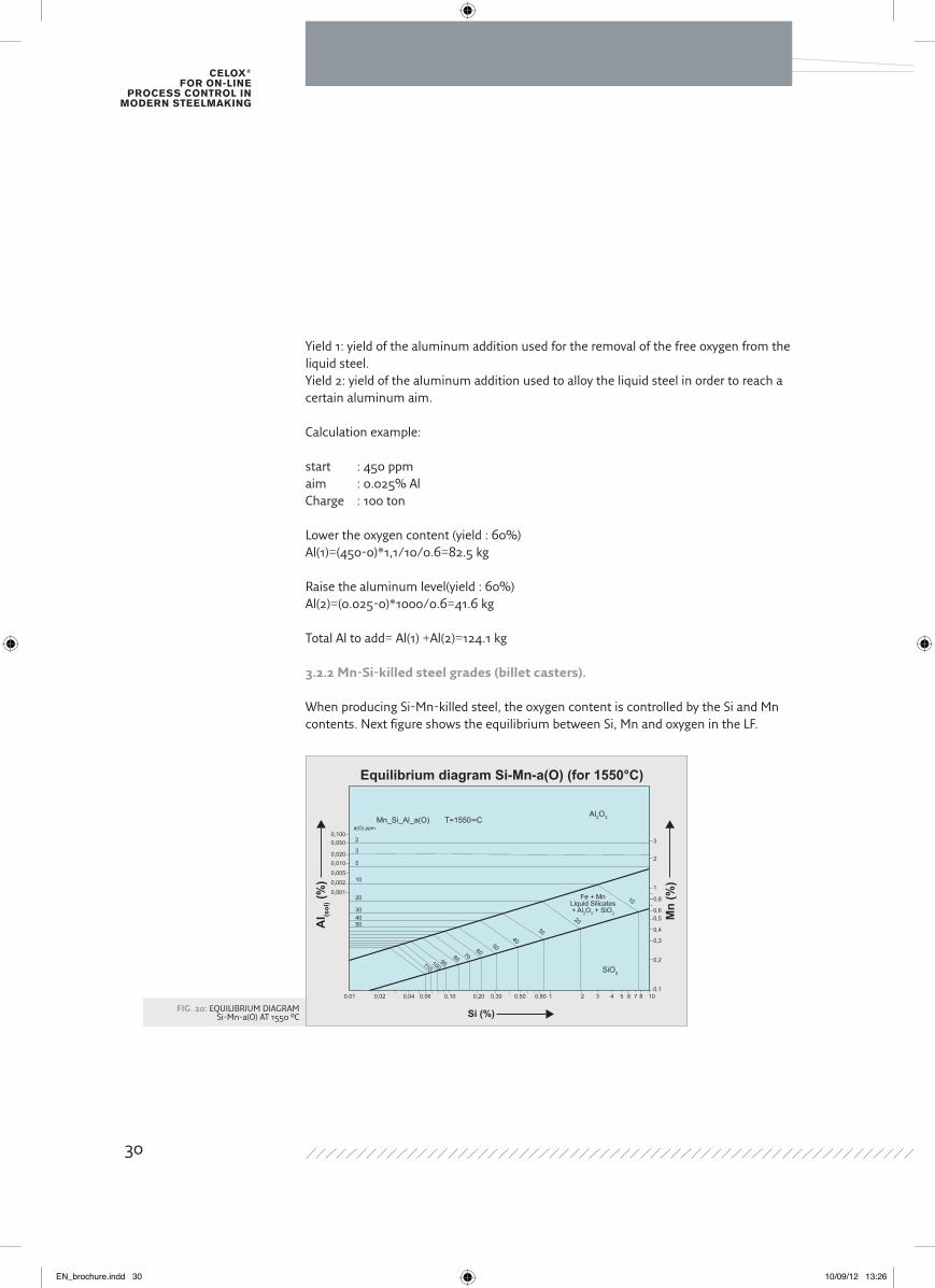
Fig. 20: EQUILIBRIUM DIAGRAM Si-Mn-a(O) AT 1550 °C
Yield 1: yield of the aluminum addition used for the removal of the free oxygen from the liquid steel.Yield 2: yield of the aluminum addition used to alloy the liquid steel in order to reach a certain aluminum aim.
Calculation example:
start : 450 ppmaim : 0.025% AlCharge : 100 ton
Lower the oxygen content (yield : 60%)Al(1)=(450-0)*1,1/10/0.6=82.5 kg
Raise the aluminum level(yield : 60%)Al(2)=(0.025-0)*1000/0.6=41.6 kg
Total Al to add= Al(1) +Al(2)=124.1 kg
3.2.2 Mn-Si-killed steel grades (billet casters).
when producing Si-Mn-killed steel, the oxygen content is controlled by the Si and Mn contents. Next figure shows the equilibrium between Si, Mn and oxygen in the LF.
Si (%)
Equilibrium diagram Si-Mn-a(O) (for 1550°C)
20,1000,050
0,0200,010
0,005
0,002
0,001
0,01 0,02 0,04 0,06 0,10 0,20 0,30 0,50 0,80 1 2 3 4 5 6 7 8 100,1
0,2
0,3
0,4
0,50,6
0,8
1
2
3
10
2030
405060708090100110
Fe + MnLiquid Silicates+ Al2O3 + SiO2
Al2O3
SiO2
Mn_Si_Al_a(O) T=1550∞C
3
5
10
20
304050A
l (sol
) (%
)
Mn
(%)
a(O) ppm
30
EN_brochure.indd 30 10/09/12 13:26
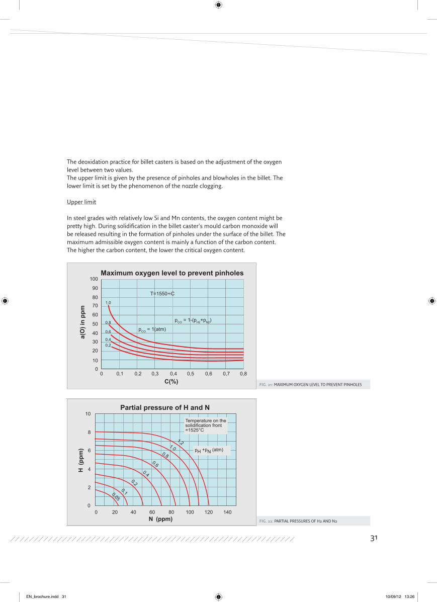
Fig. 21: MAXIMUM OXYGEN LEVEL TO PREVENT PINHOLES
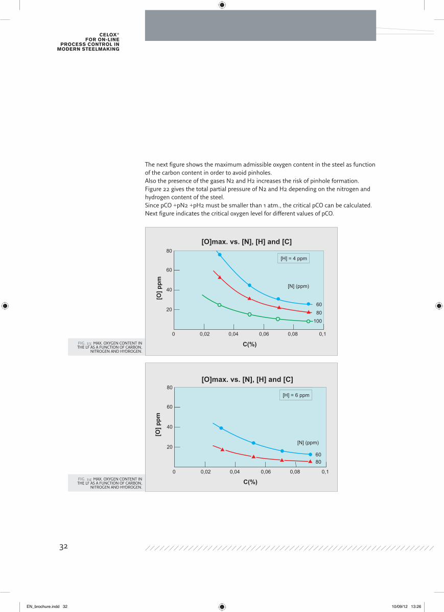
Fig. 22: PARTIAL PRESSURES OF H2 AND N2
The deoxidation practice for billet casters is based on the adjustment of the oxygen level between two values.The upper limit is given by the presence of pinholes and blowholes in the billet. The lower limit is set by the phenomenon of the nozzle clogging.
Upper limit
In steel grades with relatively low Si and Mn contents, the oxygen content might be pretty high. During solidification in the billet caster’s mould carbon monoxide will be released resulting in the formation of pinholes under the surface of the billet. The maximum admissible oxygen content is mainly a function of the carbon content. The higher the carbon content, the lower the critical oxygen content.
a(O
) in
ppm
C(%)
Maximum oxygen level to prevent pinholes
T=1550∞C
pCO = 1(atm)
pCO = 1-(pH2+pN2)
100
90
8070
60
50
40
30
20
10
00 0,1 0,2 0,3 0,4 0,5 0,6 0,7 0,8
1,0
0,8
0,6
0,40,2
Partial pressure of H and N10
8
6
4
2
00 20 40 60 80 100 120 140
N (ppm)
H (p
pm)
1.21.0
0.80.6
0.4
0.2
0.10.05
pH +pN (atm)
Temperature on thesolidification front=1525°C
31
EN_brochure.indd 31 10/09/12 13:26
Celox® for on-line
proCess Control in modern steelmaking
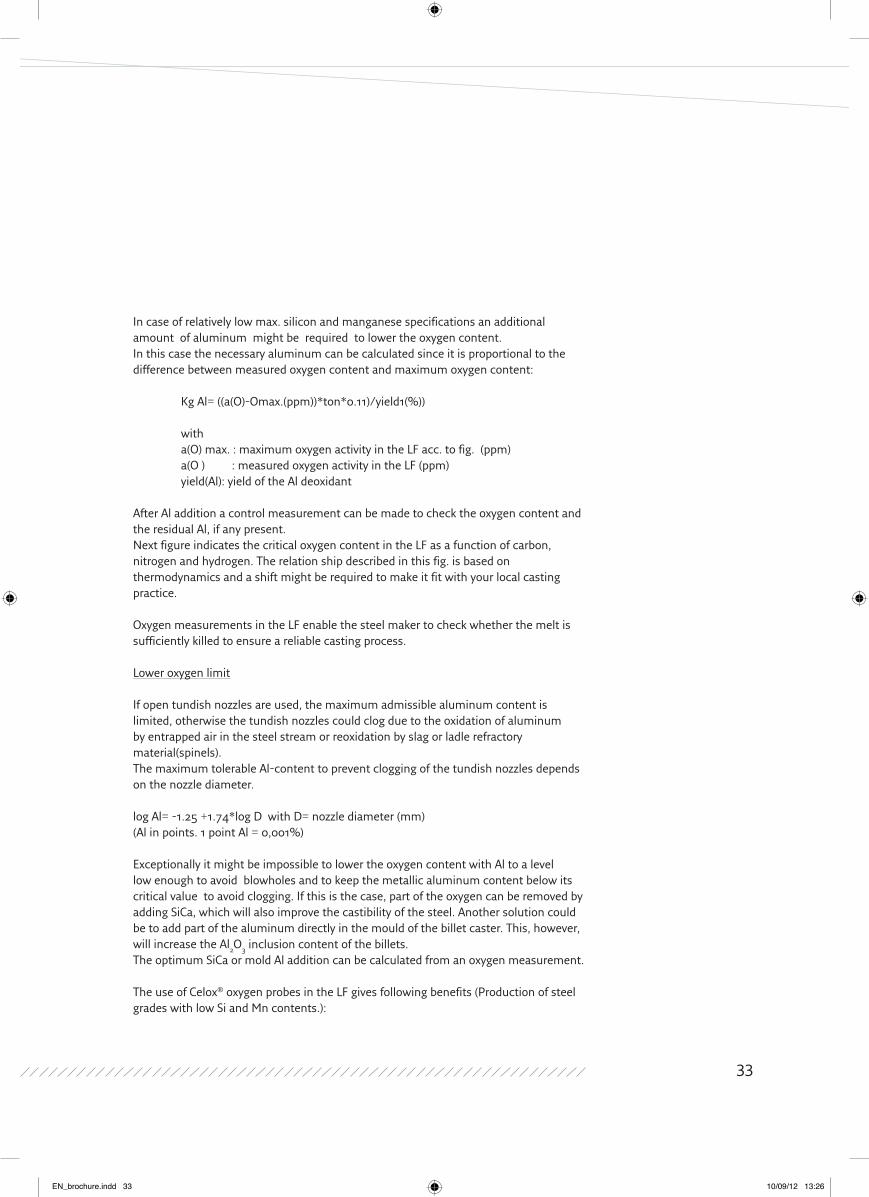
Fig. 23: MAX. OXYGEN CONTENT IN THE LF AS A FUNCTION OF CARBON,
NITROGEN AND HYDROGEN.
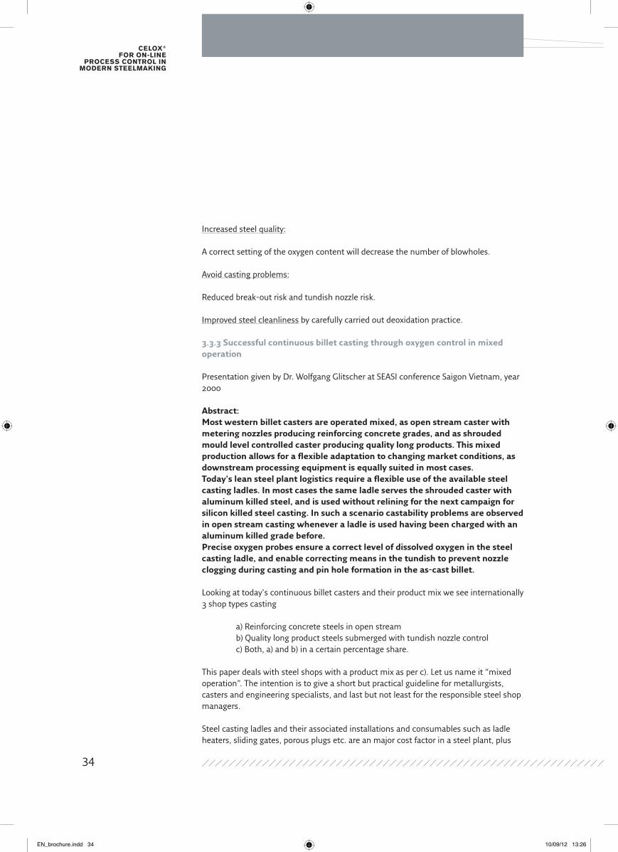
Fig. 24: MAX. OXYGEN CONTENT IN THE LF AS A FUNCTION OF CARBON,
NITROGEN AND HYDROGEN.
The next figure shows the maximum admissible oxygen content in the steel as function of the carbon content in order to avoid pinholes.Also the presence of the gases N2 and H2 increases the risk of pinhole formation.Figure 22 gives the total partial pressure of N2 and H2 depending on the nitrogen and hydrogen content of the steel.Since pCO +pN2 +pH2 must be smaller than 1 atm., the critical pCO can be calculated.Next figure indicates the critical oxygen level for different values of pCO.
[O]max. vs. [N], [H] and [C]
C(%)
[O] p
pm
80
60
40
20
0 0,02 0,04 0,06 0,08
[H] = 4 ppm
[N] (ppm)
0,1
6080
100
C(%)
[O] p
pm
80
60
40
20
0 0,02 0,04 0,06 0,08
[H] = 6 ppm
[N] (ppm)
0,1
6080
[O]max. vs. [N], [H] and [C]
32
EN_brochure.indd 32 10/09/12 13:26
In case of relatively low max. silicon and manganese specifications an additional amount of aluminum might be required to lower the oxygen content.In this case the necessary aluminum can be calculated since it is proportional to the difference between measured oxygen content and maximum oxygen content:
Kg Al= ((a(O)-Omax.(ppm))*ton*0.11)/yield1(%))
with a(O) max. : maximum oxygen activity in the LF acc. to fig. (ppm) a(O ) : measured oxygen activity in the LF (ppm) yield(Al): yield of the Al deoxidant
After Al addition a control measurement can be made to check the oxygen content and the residual Al, if any present.Next figure indicates the critical oxygen content in the LF as a function of carbon, nitrogen and hydrogen. The relation ship described in this fig. is based on thermodynamics and a shift might be required to make it fit with your local casting practice.
Oxygen measurements in the LF enable the steel maker to check whether the melt is sufficiently killed to ensure a reliable casting process. Lower oxygen limit
If open tundish nozzles are used, the maximum admissible aluminum content is limited, otherwise the tundish nozzles could clog due to the oxidation of aluminum by entrapped air in the steel stream or reoxidation by slag or ladle refractory material(spinels).The maximum tolerable Al-content to prevent clogging of the tundish nozzles depends on the nozzle diameter.
log Al= -1.25 +1.74*log D with D= nozzle diameter (mm) (Al in points. 1 point Al = 0,001%)
Exceptionally it might be impossible to lower the oxygen content with Al to a level low enough to avoid blowholes and to keep the metallic aluminum content below its critical value to avoid clogging. If this is the case, part of the oxygen can be removed by adding SiCa, which will also improve the castibility of the steel. Another solution could be to add part of the aluminum directly in the mould of the billet caster. This, however, will increase the Al2O3 inclusion content of the billets.The optimum SiCa or mold Al addition can be calculated from an oxygen measurement.
The use of Celox® oxygen probes in the LF gives following benefits (Production of steel grades with low Si and Mn contents.):
33
EN_brochure.indd 33 10/09/12 13:26
Celox® for on-line
proCess Control in modern steelmaking
Increased steel quality:
A correct setting of the oxygen content will decrease the number of blowholes.
Avoid casting problems: Reduced break-out risk and tundish nozzle risk.
Improved steel cleanliness by carefully carried out deoxidation practice.
3.3.3 Successful continuous billet casting through oxygen control in mixed operation
Presentation given by Dr. wolfgang Glitscher at SEASI conference Saigon Vietnam, year 2000
Abstract:Most western billet casters are operated mixed, as open stream caster with metering nozzles producing reinforcing concrete grades, and as shrouded mould level controlled caster producing quality long products. This mixed production allows for a flexible adaptation to changing market conditions, as downstream processing equipment is equally suited in most cases.Today’s lean steel plant logistics require a flexible use of the available steel casting ladles. in most cases the same ladle serves the shrouded caster with aluminum killed steel, and is used without relining for the next campaign for silicon killed steel casting. in such a scenario castability problems are observed in open stream casting whenever a ladle is used having been charged with an aluminum killed grade before.Precise oxygen probes ensure a correct level of dissolved oxygen in the steel casting ladle, and enable correcting means in the tundish to prevent nozzle clogging during casting and pin hole formation in the as-cast billet.
Looking at today’s continuous billet casters and their product mix we see internationally 3 shop types casting
a) Reinforcing concrete steels in open stream b) Quality long product steels submerged with tundish nozzle control c) Both, a) and b) in a certain percentage share.
This paper deals with steel shops with a product mix as per c). Let us name it “mixed operation”. The intention is to give a short but practical guideline for metallurgists, casters and engineering specialists, and last but not least for the responsible steel shop managers.
Steel casting ladles and their associated installations and consumables such as ladle heaters, sliding gates, porous plugs etc. are an major cost factor in a steel plant, plus
34
EN_brochure.indd 34 10/09/12 13:26
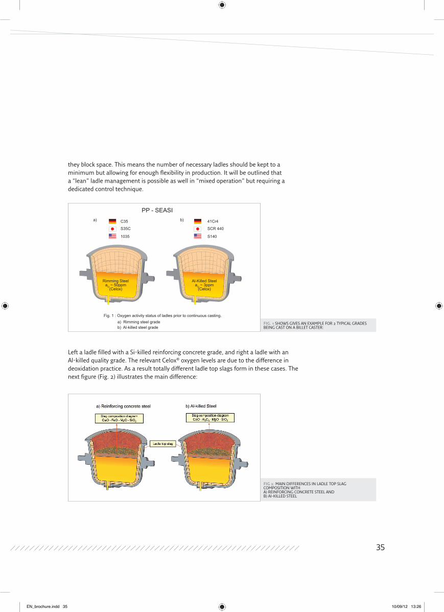
Fig. 1 SHOwS GIVES AN EXAMPLE FOR 2 TYPICAL GRADES BEING CAST ON A BILLET CASTER:
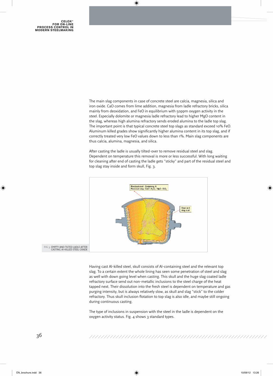
Fig 2: MAIN DIFFERENCES IN LADLE TOP SLAG COMPOSITION wITH A) REINFORCING CONCRETE STEEL AND B) Al-KILLED STEEL
they block space. This means the number of necessary ladles should be kept to a minimum but allowing for enough flexibility in production. It will be outlined that a “lean” ladle management is possible as well in “mixed operation” but requiring a dedicated control technique.
Left a ladle filled with a Si-killed reinforcing concrete grade, and right a ladle with an Al-killed quality grade. The relevant Celox® oxygen levels are due to the difference in deoxidation practice. As a result totally different ladle top slags form in these cases. The next figure (Fig. 2) illustrates the main difference:
Al-Killed SteelaO ~ 3ppm
(Celox)
Rimming SteelaO ~ 50ppm
(Celox)
C35 41Cr4
S35C SCR 440
1035 S140
PP - SEASI
Fig. 1 : Oxygen activity status of ladles prior to continuous casting. a) Rimming steel gradeb) Al-killed steel grade
a) b)
35
EN_brochure.indd 35 10/09/12 13:26
Celox® for on-line
proCess Control in modern steelmaking
Fig 3: EMPTY AND TILTED LADLE AFTER CASTING Al-KILLED STEEL GRADE
The main slag components in case of concrete steel are calcia, magnesia, silica and iron oxide. CaO comes from lime addition, magnesia from ladle refractory bricks, silica mainly from deoxidation, and FeO in equilibrium with 50ppm oxygen activity in the steel. Especially dolomite or magnesia ladle refractory lead to higher MgO content in the slag, whereas high alumina refractory sends eroded alumina to the ladle top slag. The important point is that typical concrete steel top slags as standard exceed 10% FeO. Aluminum killed grades show significantly higher alumina content in its top slag, and if correctly treated very low FeO values down to less than 1%. Main slag components are thus calcia, alumina, magnesia, and silica.
After casting the ladle is usually tilted-over to remove residual steel and slag. Dependent on temperature this removal is more or less successful. with long waiting for cleaning after end of casting the ladle gets “sticky” and part of the residual steel and top slag stay inside and form skull, Fig. 3.
Having cast Al-killed steel, skull consists of Al-containing steel and the relevant top slag. To a certain extent the whole lining has seen some penetration of steel and slag as well with down going level when casting. This skull and the huge slag coated ladle refractory surface send out non-metallic inclusions to the steel charge of the heat tapped next. Their dissolution into the fresh steel is dependent on temperature and gas purging intensity, but is always relatively slow, as skull and slag “stick” to the colder refractory. Thus skull inclusion flotation to top slag is also idle, and maybe still ongoing during continuous casting. The type of inclusions in suspension with the steel in the ladle is dependent on the oxygen activity status. Fig. 4 shows 3 standard types.
36
EN_brochure.indd 36 10/09/12 13:26
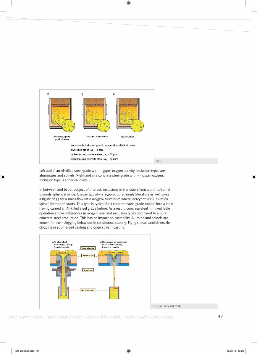
Fig 4
Fig 5: BILLET CASTER TYPES
Left and a) an Al-killed steel grade with ~ 3ppm oxygen activity. Inclusion types are aluminates and spinels. Right and c) a concrete steel grade with ~ 50ppm oxygen. Inclusion type is spherical oxide.
In between and b) our subject of interest: inclusions in transition from alumina/spinel towards spherical oxide. Oxygen activity is 35ppm. Surprisingly literature as well gives a figure of 35 for a mass flow ratio oxygen/aluminum where Hercynite (FeO-alumina spinel) formation starts. This type is typical for a concrete steel grade tapped into a ladle having carried an Al-killed steel grade before. As a result, concrete steel in mixed ladle operation shows differences in oxygen level and inclusion types compared to a pure concrete steel production. This has an impact on castability. Alumina and spinels are known for their clogging behaviour in continuous casting. Fig. 5 shows tundish nozzle clogging in submerged casting and open stream casting.
37
EN_brochure.indd 37 10/09/12 13:26
Celox® for on-line
proCess Control in modern steelmaking
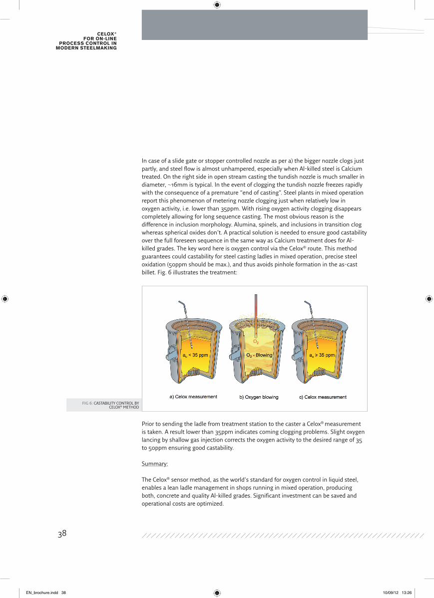
Fig 6: CASTABILITY CONTROL BY CELOX® METHOD
In case of a slide gate or stopper controlled nozzle as per a) the bigger nozzle clogs just partly, and steel flow is almost unhampered, especially when Al-killed steel is Calcium treated. On the right side in open stream casting the tundish nozzle is much smaller in diameter, ~16mm is typical. In the event of clogging the tundish nozzle freezes rapidly with the consequence of a premature “end of casting”. Steel plants in mixed operation report this phenomenon of metering nozzle clogging just when relatively low in oxygen activity, i.e. lower than 35ppm. with rising oxygen activity clogging disappears completely allowing for long sequence casting. The most obvious reason is the difference in inclusion morphology. Alumina, spinels, and inclusions in transition clog whereas spherical oxides don’t. A practical solution is needed to ensure good castability over the full foreseen sequence in the same way as Calcium treatment does for Al-killed grades. The key word here is oxygen control via the Celox® route. This method guarantees could castability for steel casting ladles in mixed operation, precise steel oxidation (50ppm should be max.), and thus avoids pinhole formation in the as-cast billet. Fig. 6 illustrates the treatment:
Prior to sending the ladle from treatment station to the caster a Celox® measurement is taken. A result lower than 35ppm indicates coming clogging problems. Slight oxygen lancing by shallow gas injection corrects the oxygen activity to the desired range of 35 to 50ppm ensuring good castability.
Summary:
The Celox® sensor method, as the world’s standard for oxygen control in liquid steel, enables a lean ladle management in shops running in mixed operation, producing both, concrete and quality Al-killed grades. Significant investment can be saved and operational costs are optimized.
38
EN_brochure.indd 38 10/09/12 13:26
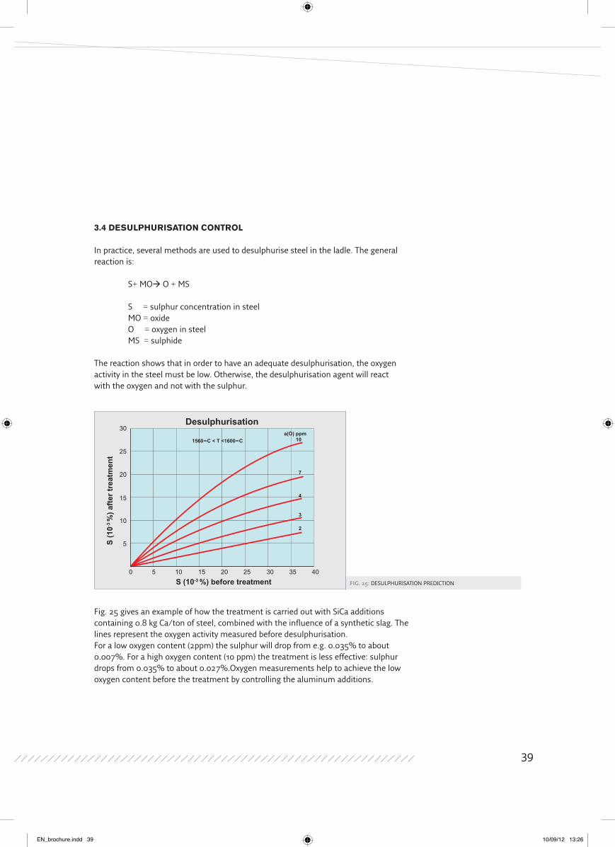
Fig. 25: DESULPHURISATION PREDICTION
3.4 dEsUlPHURIsAtIoN CoNtRol
In practice, several methods are used to desulphurise steel in the ladle. The general reaction is:
S+ MO O + MS
S = sulphur concentration in steel MO = oxide O = oxygen in steel MS = sulphide
The reaction shows that in order to have an adequate desulphurisation, the oxygen activity in the steel must be low. Otherwise, the desulphurisation agent will reactwith the oxygen and not with the sulphur.
Fig. 25 gives an example of how the treatment is carried out with SiCa additions containing 0.8 kg Ca/ton of steel, combined with the influence of a synthetic slag. The lines represent the oxygen activity measured before desulphurisation.For a low oxygen content (2ppm) the sulphur will drop from e.g. 0.035% to about 0.007%. For a high oxygen content (10 ppm) the treatment is less effective: sulphur drops from 0.035% to about 0.027%.Oxygen measurements help to achieve the low oxygen content before the treatment by controlling the aluminum additions.
Desulphurisation
0
5
10
15
20
25
30
5 10 15 20 25 30 35 40
a(O) ppm10
7
4
3
2
S (10-3 %) before treatment
S (1
0-3 %
) afte
r tre
atm
ent
1560∞C < T <1600∞C
39
EN_brochure.indd 39 10/09/12 13:26

Celox® for on-line
proCess Control in modern steelmaking
NotEs
40
EN_brochure.indd 40 10/09/12 13:26

NotEs
41
EN_brochure.indd 41 10/09/12 13:26
Celox® for on-line
proCess Control in modern steelmaking
NotEs
42
EN_brochure.indd 42 10/09/12 13:26

EN_brochure.indd 43 10/09/12 13:26

Heraeus Electro-Nite International N.V.Centrum Zuid 11053530 Houthalen, Belgium
Phone + 32 (0) 11 / 60 02 11Fax + 32 (0) 11 / 60 04 00E-mail: [email protected]
Des
ign:
ww
w.ta
beok
a.be
- D
ate
of p
rint:
00/0
0/2
010
EN_brochure.indd 44 10/09/12 13:26