cement kiln catalogue -...
TRANSCRIPT

CEMENT KILN BURNERS Catalogue
2014

In 2004, a few months after foundation, Dynamis installed its first burner at a Votorantim
Cimentos plant in Brazil. The entire process of conceiving and delivering such equipment
represented an important achievement for the company and helped establishing its mindset for
the following decade: deliver innovative solutions to clients’ demands, constantly aiming
energy efficiency and operational cost reduction.
Almost a decade later, Dynamis has installed more than 60 fully operational burners, which are
responsible for over 40% of the clinker production in Brazil - 4th biggest cement market in the
world - and 60% in Argentina.
The company's main clients are Votorantim Corporation, #1 cement company in Brazil (and one
of the top-ten players in the world, excluding China), with approximately 40% market share,
and InterCement, who recently acquired Cimpor Corporation to become the 2nd largest cement
company in Brazil, with approximately 25% market share. The company has also provided
burner installations for Nassau, Ciplan, Supremo, Apodi and Elizabeth.
Dynamis' innovative thinking has recently captured the attention of international companies,
leading to the development of projects for Heidelberg Group/ Cementa AB - Degenham/
Sweden, Holcim Malagueño - Córdoba/ Argentina, Ciments de Sibline – Beiruth/ Lebanon, and
traditional engineering and equipment suppliers like LVT, Outotec and Krupp Polysius.
Experience and Innovation AT YOUR SERVICE
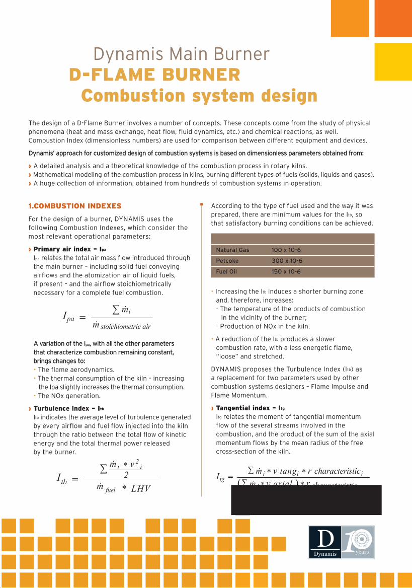
According to the type of fuel used and the way it was prepared, there are minimum values for the Itb, so that satisfactory burning conditions can be achieved.
• Increasing the Itb induces a shorter burning zone and, therefore, increases: - The temperature of the products of combustion in the vicinity of the burner; - Production of NOx in the kiln.
• A reduction of the Itb produces a slower combustion rate, with a less energetic flame, “loose” and stretched.
DYNAMIS proposes the Turbulence Index (Itb) as a replacement for two parameters used by other combustion systems designers – Flame Impulse and Flame Momentum.
› Tangential index – Itg
Itg relates the moment of tangential momentum flow of the several streams involved in the combustion, and the product of the sum of the axial momentum flows by the mean radius of the free cross-section of the kiln.
Dynamis Main BurnerD-FLAME BURNER Combustion system design
The design of a D-Flame Burner involves a number of concepts. These concepts come from the study of physical phenomena (heat and mass exchange, heat flow, fluid dynamics, etc.) and chemical reactions, as well. Combustion Index (dimensionless numbers) are used for comparison between different equipment and devices.
Dynamis’ approach for customized design of combustion systems is based on dimensionless parameters obtained from:
› A detailed analysis and a theoretical knowledge of the combustion process in rotary kilns.› Mathematical modeling of the combustion process in kilns, burning different types of fuels (solids, liquids and gases).› A huge collection of information, obtained from hundreds of combustion systems in operation.
1.COMBUSTION INDEXES
For the design of a burner, DYNAMIS uses the following Combustion Indexes, which consider the most relevant operational parameters:
› Primary air index – Ipa
Ipa relates the total air mass flow introduced through the main burner – including solid fuel conveying airflows and the atomization air of liquid fuels, if present – and the airflow stoichiometrically necessary for a complete fuel combustion.
A variation of the Ipa, with all the other parameters that characterize combustion remaining constant, brings changes to: • The flame aerodynamics. • The thermal consumption of the kiln – increasing the Ipa slightly increases the thermal consumption. • The NOx generation.
› Turbulence index – Itb
Itb indicates the average level of turbulence generated by every airflow and fuel flow injected into the kiln through the ratio between the total flow of kinetic energy and the total thermal power released by the burner.
FUEL MINIMUM TURBULENCE INDEX
Natural Gas 100 x 10-6
Petcoke 300 x 10-6
Fuel Oil 150 x 10-6
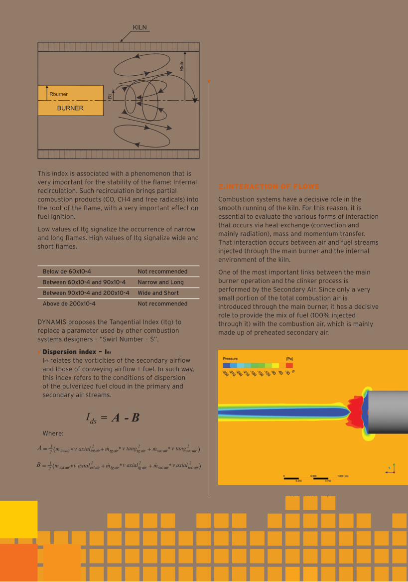
This index is associated with a phenomenon that is very important for the stability of the flame: Internal recirculation. Such recirculation brings partial combustion products (CO, CH4 and free radicals) into the root of the flame, with a very important effect on fuel ignition.
Low values of Itg signalize the occurrence of narrow and long flames. High values of Itg signalize wide and short flames.
DYNAMIS proposes the Tangential Index (Itg) to replace a parameter used by other combustion systems designers – “Swirl Number – S”.
› Dispersion index – Ids
Ids relates the vorticities of the secondary airflow and those of conveying airflow + fuel. In such way, this index refers to the conditions of dispersion of the pulverized fuel cloud in the primary and secondary air streams.
Where:
TANGENTIAL INDEX (ITG) FLAME GEOMETRY
Below de 60x10-4 Not recommended
Between 60x10-4 and 90x10-4 Narrow and Long
Between 90x10-4 and 200x10-4 Wide and Short
Above de 200x10-4 Not recommended
DYNAMIS strongly recommends not to evaluate main burners only taking into account a single combustion index (Flame Momentum or Flame Impulse, for example). This poor analysis can lead to false conclusions,which usually lead to maximizing only one parameter at the expense of many others, which also have great importance to combustion itself and the process carried out inside the kiln, as well.
2.INTERACTION OF FLOWS
Combustion systems have a decisive role in the smooth running of the kiln. For this reason, it is essential to evaluate the various forms of interaction that occurs via heat exchange (convection and mainly radiation), mass and momentum transfer. That interaction occurs between air and fuel streams injected through the main burner and the internal environment of the kiln.
One of the most important links between the main burner operation and the clinker process is performed by the Secondary Air. Since only a very small portion of the total combustion air is introduced through the main burner, it has a decisive role to provide the mix of fuel (100% injected through it) with the combustion air, which is mainly made up of preheated secondary air.
Pressure Profile Close to Burner Tip
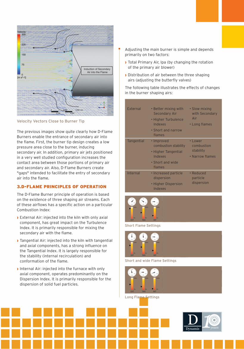
The previous images show quite clearly how D-Flame Burners enable the entrance of secondary air into the flame. First, the burner tip design creates a low pressure area close to the burner, inducing secondary air. In addition, primary air jets positioned in a very well studied configuration increases the contact area between those portions of primary air and secondary air. Also, D-Flame Burners create "gaps" intended to facilitate the entry of secondary air into the flame.
Velocity Vectors Close to Burner Tip
Short Flame Settings
Short and wide Flame Settings
Long Flame Settings
3.D-FLAME PRINCIPLES OF OPERATION
The D-Flame Burner principle of operation is based on the existence of three shaping air streams. Each of these airflows has a specific action on a particular Combustion Index:
› External Air: injected into the kiln with only axial component, has great impact on the Turbulence Index. It is primarily responsible for mixing the secondary air with the flame.
› Tangential Air: injected into the kiln with tangential and axial components, has a strong influence on the Tangential Index. It is largely responsible for the stability (internal recirculation) and conformation of the flame.
› Internal Air: injected into the furnace with only axial component, operates predominantly on the Dispersion Index. It is primarily responsible for the dispersion of solid fuel particles.
Adjusting the main burner is simple and depends primarily on two factors:
› Total Primary Air, Ipa (by changing the rotation of the primary air blower)
› Distribution of air between the three shaping airs (adjusting the butterfly valves)
The following table illustrates the effects of changes in the burner shaping airs:
SHAPING AIR INCREASING AIRFLOW REDUCING AIRFLOW
• Slow mixing with Secondary Air
• Long flames
• Lower combustion stability
• Narrow flames
• Reduced particle dispersion
• Better mixing with Secondary Air
• Higher Turbulence Indexes
• Short and narrow flames
• Improved combustion stability
• Higher Tangential Indexes
• Short and wide flames
• Increased particle dispersion
• Higher Dispersion Indexes
External
Tangential
Internal
100%
0%
EXT
300
600
mbar
0
100%
0%
TAN
300
600
mbar
0
100%
0%
INT
300
600
mbar
0
100%
0%
EXT
300
600
mbar
0
100%
0%
TAN
300
600
mbar
0
100%
0%
INT
300
600
mbar
0
100%
0%
EXT
300
600
mbar
0
100%
0%
TAN
300
600
mbar
0
100%
0%
INT
300
600
mbar
0

D-Flame Burners are tailor-made to each client’s specific needs, which usually involve demands such as: high flame turbulence indexes, flexibility for using different fuels, control of greenhouse gases, necessity of burning industrial waste and even uncontrolable parameters like how to answer to seasonality impact on certain fuels availability. All these demands have direct influence on each burner design attributes.
Ranging from 10 to 100Gcal/h, D-Flame Burners are designed to operate with pulverized solid fuels (petcoke, coal, charcoal), gaseous fuels (natural gas, LPG), fuel oil (diesel and ultra-viscous oils) besides liquid, pasty and solid industrial waste.
D-Flame BURNERS
D-Flame Burners are highly flexible, giving the operator better process control – thermal profile, heating rate, flame shape and more. After heating up, D-Flame Burners give a more stable coating formation, avoiding unburned material during initial operation.
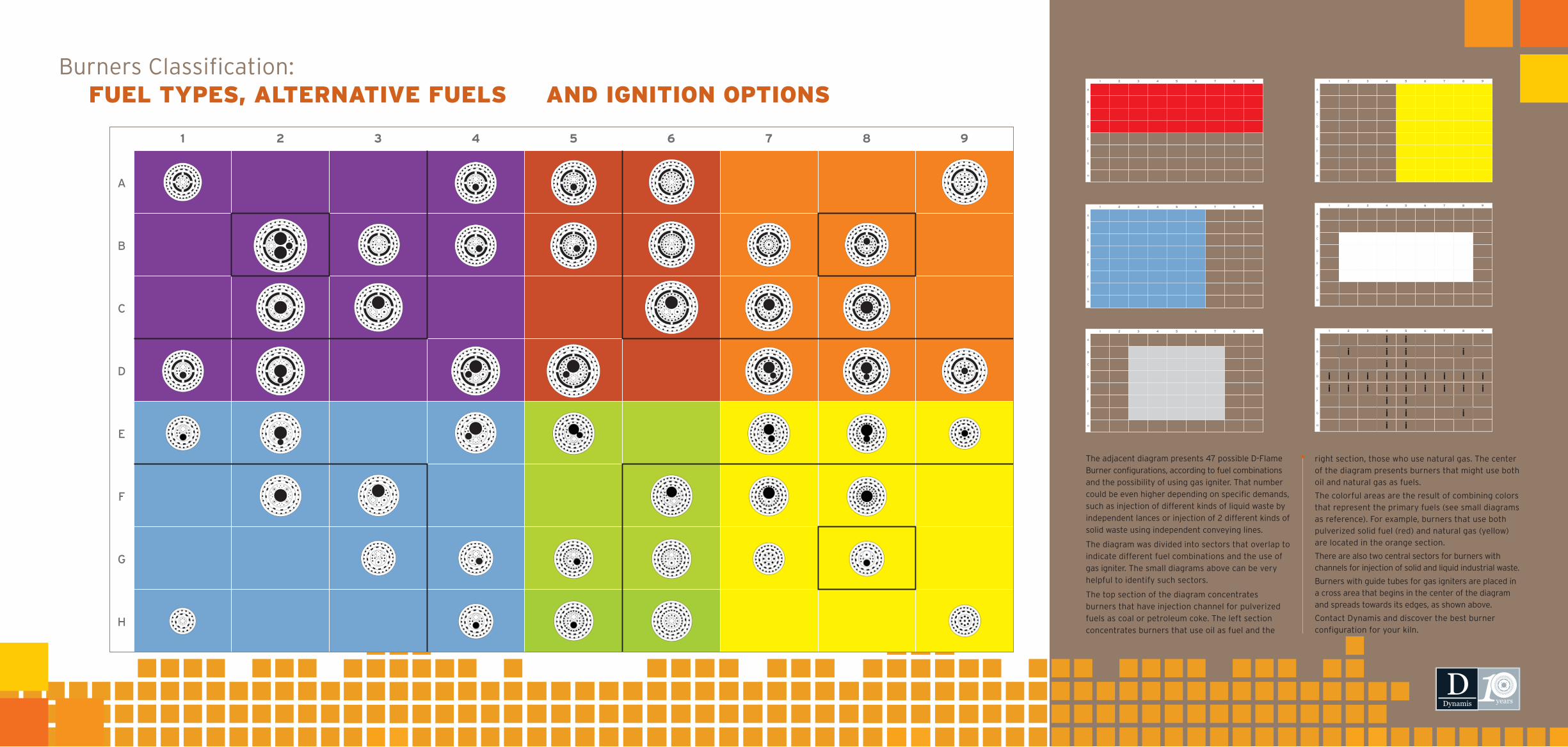
The adjacent diagram presents 47 possible D-Flame
Burner configurations, according to fuel combinations
and the possibility of using gas igniter. That number
could be even higher depending on specific demands,
such as injection of different kinds of liquid waste by
independent lances or injection of 2 different kinds of
solid waste using independent conveying lines.
The diagram was divided into sectors that overlap to
indicate different fuel combinations and the use of
gas igniter. The small diagrams above can be very
helpful to identify such sectors.
The top section of the diagram concentrates
burners that have injection channel for pulverized
fuels as coal or petroleum coke. The left section
concentrates burners that use oil as fuel and the
Burners Classification: FUEL TYPES, ALTERNATIVE FUELS AND IGNITION OPTIONS
right section, those who use natural gas. The center of the diagram presents burners that might use both oil and natural gas as fuels.
The colorful areas are the result of combining colors that represent the primary fuels (see small diagrams as reference). For example, burners that use both pulverized solid fuel (red) and natural gas (yellow) are located in the orange section.
There are also two central sectors for burners with channels for injection of solid and liquid industrial waste.
Burners with guide tubes for gas igniters are placed in a cross area that begins in the center of the diagram and spreads towards its edges, as shown above.
Contact Dynamis and discover the best burner configuration for your kiln.
A
1 2 3 4 5 6 7 8 9
B
C
D
E
F
G
H
PULVERIZED FUEL
A
1 2 3 4 5 6 7 8 9
B
C
D
E
F
G
H
NATURAL GAS
A
1 2 3 4 5 6 7 8 9
B
C
D
E
F
G
H
OIL
A
1 2 3 4 5 6 7 8 9
B
C
D
E
F
G
H
SOLID WASTE
A
1 2 3 4 5 6 7 8 9
B
C
D
E
F
G
H
LIQUID WASTE
A
1 2 3 4 5 6 7 8 9
B
C
D
E
F
G
H
IGNITER
A
1 2 3 4 5 6 7 8 9
B
C
D
E
F
G
H

Dynamis sustains that calciner burners should be treated similarly to main burners. This means that many considerations regarding the interaction between the fuel jet and the calciner internal environment must be taken in account when studying the combustion in a calciner. Such conditions may vary considerably depending on the type of calciner, reason why there is an ideal burner for each calciner configuration.
For example, the combustion conditions inside a modern separate-line calciner with vertical combustion chamber are very different from those inside an in-line calciner. The first one can operate with a hot dust-free core and the tertiary air flowing along the internal walls defining a spinning pattern. As well, the raw meal admission into the equipment can be designed to keep higher dust concentrations only at the chamber periphery.
On the other hand, the in-line calciner does not have a hot core, and its internal atmosphere is heavily loaded with dust. So, the fuel ignition happens in very poor conditions. Therefore, it is important to define the number of fuel injection points and the best location for such injection into this kind of calciner. Additionally, it is very important to provide the best ignition conditions to the fuel, which can only be obtained with high-turbulence burners. Dynamis makes complete calciner CFD modeling to find the optimum location to install the burners. Both modeling and field measurements are clear in showing how calciner burners are important to allow the best use of the in-line calciner volume, if compared to single injection tubes.
Dynamis CALCINER BURNER
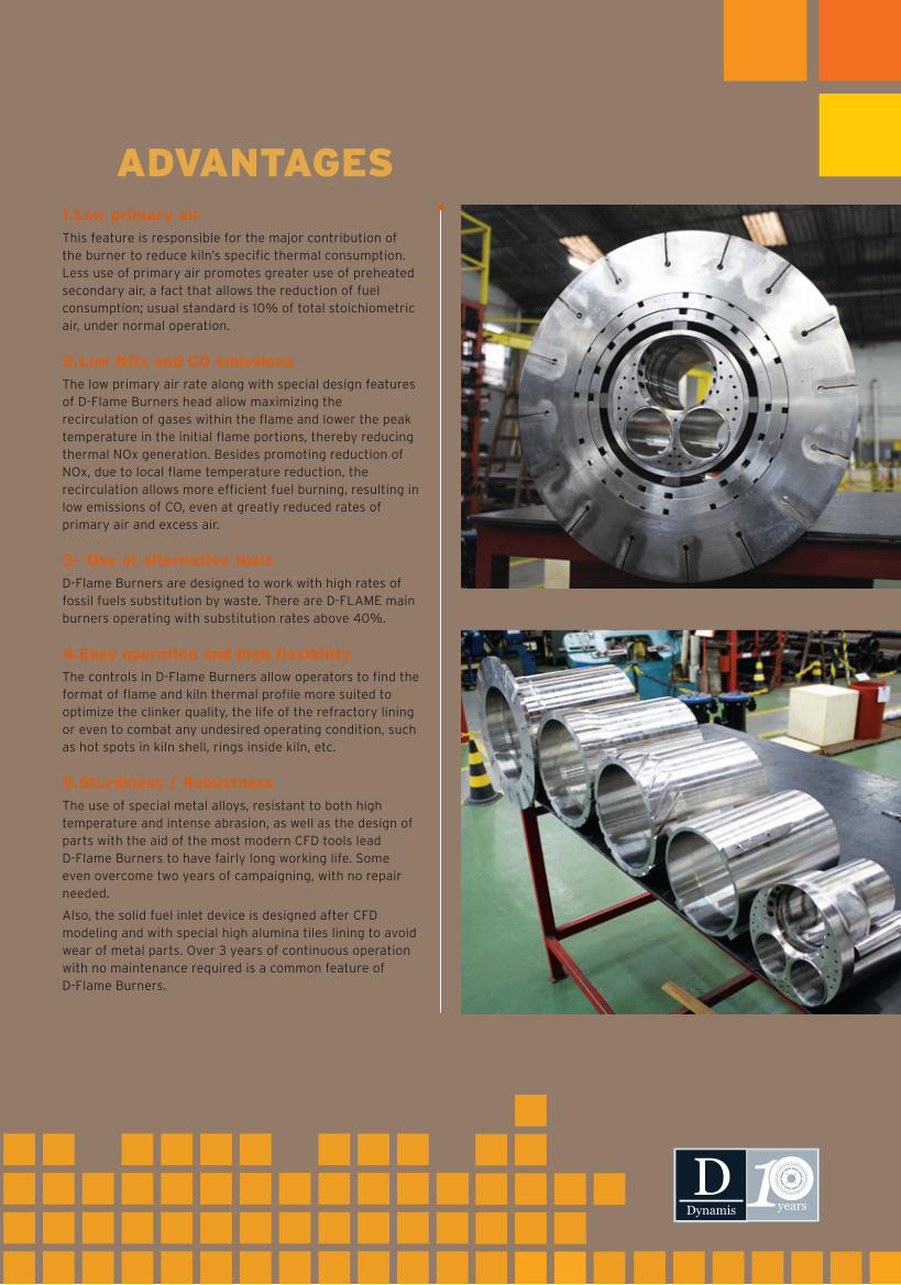
1.Low primary airThis feature is responsible for the major contribution of the burner to reduce kiln’s specific thermal consumption. Less use of primary air promotes greater use of preheated secondary air, a fact that allows the reduction of fuel consumption; usual standard is 10% of total stoichiometric air, under normal operation.
2.Low NOx and CO emissionsThe low primary air rate along with special design features of D-Flame Burners head allow maximizing the recirculation of gases within the flame and lower the peak temperature in the initial flame portions, thereby reducing thermal NOx generation. Besides promoting reduction of NOx, due to local flame temperature reduction, the recirculation allows more efficient fuel burning, resulting in low emissions of CO, even at greatly reduced rates of primary air and excess air.
3- Use of alternative fuelsD-Flame Burners are designed to work with high rates of fossil fuels substitution by waste. There are D-FLAME main burners operating with substitution rates above 40%.
4.Easy operation and high flexibilityThe controls in D-Flame Burners allow operators to find the format of flame and kiln thermal profile more suited to optimize the clinker quality, the life of the refractory lining or even to combat any undesired operating condition, such as hot spots in kiln shell, rings inside kiln, etc.
5.Sturdiness / RobustnessThe use of special metal alloys, resistant to both high temperature and intense abrasion, as well as the design of parts with the aid of the most modern CFD tools lead D-Flame Burners to have fairly long working life. Some even overcome two years of campaigning, with no repair needed.
Also, the solid fuel inlet device is designed after CFD modeling and with special high alumina tiles lining to avoid wear of metal parts. Over 3 years of continuous operation with no maintenance required is a common feature of D-Flame Burners.
D-Flame Burner ADVANTAGES
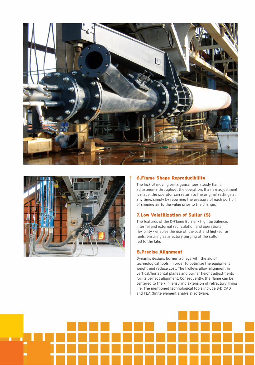
6.Flame Shape ReproducibilityThe lack of moving parts guarantees steady flame adjustments throughout the operation. If a new adjustment is made, the operator can return to the original settings at any time, simply by returning the pressure of each portion of shaping air to the value prior to the change.
7.Low Volatilization of Sulfur (S)The features of the D-Flame Burner - high turbulence, internal and external recirculation and operational flexibility - enables the use of low-cost and high-sulfur fuels, ensuring satisfactory purging of the sulfur fed to the kiln.
8.Precise AlignmentDynamis designs burner trolleys with the aid of technological tools, in order to optimize the equipment weight and reduce cost. The trolleys allow alignment in vertical/horizontal planes and burner height adjustments for its perfect alignment. Consequently, the flame can be centered to the kiln, ensuring extension of refractory lining life. The mentioned technological tools include 3-D CAD and FEA (finite element analysis) software.
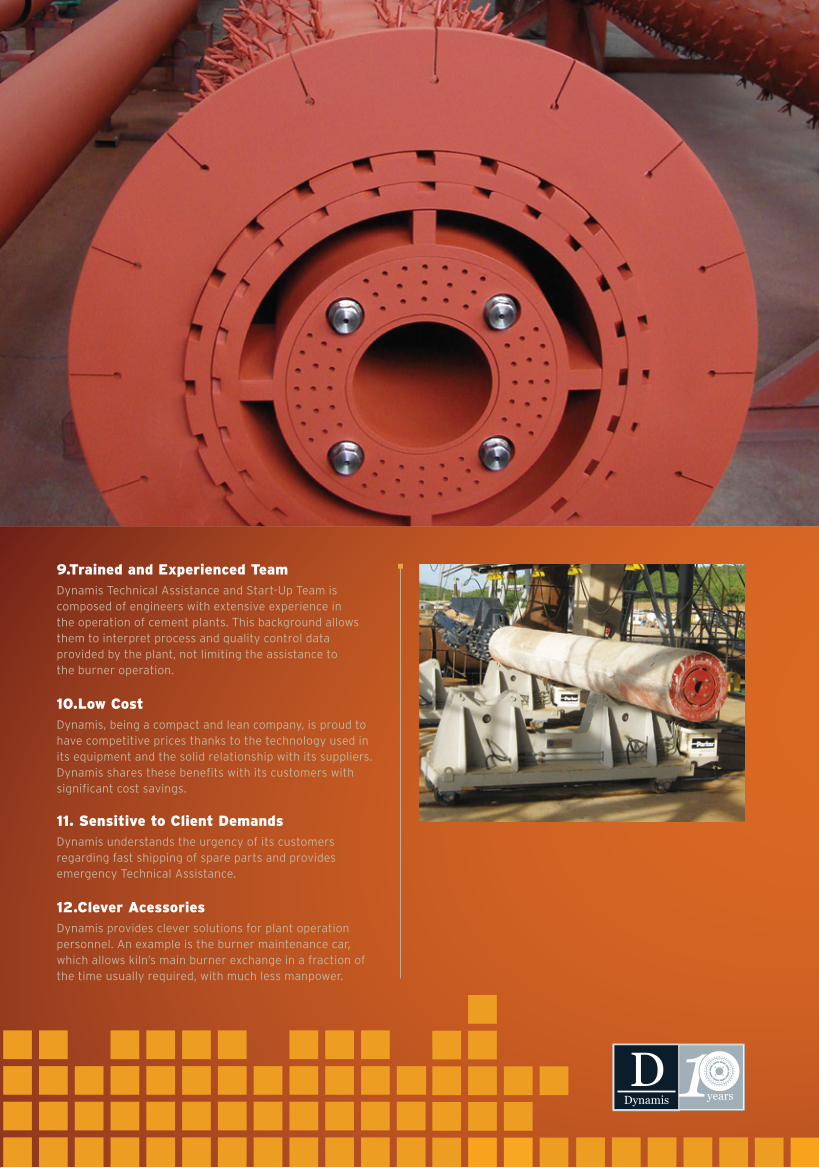
9.Trained and Experienced TeamDynamis Technical Assistance and Start-Up Team is composed of engineers with extensive experience in the operation of cement plants. This background allows them to interpret process and quality control data provided by the plant, not limiting the assistance to the burner operation.
10.Low CostDynamis, being a compact and lean company, is proud to have competitive prices thanks to the technology used in its equipment and the solid relationship with its suppliers. Dynamis shares these benefits with its customers with significant cost savings.
11. Sensitive to Client DemandsDynamis understands the urgency of its customers regarding fast shipping of spare parts and provides emergency Technical Assistance.
12.Clever AcessoriesDynamis provides clever solutions for plant operation personnel. An example is the burner maintenance car, which allows kiln’s main burner exchange in a fraction of the time usually required, with much less manpower.
1.Low primary airThis feature is responsible for the major contribution of the burner to reduce kiln’s specific thermal consumption. Less use of primary air promotes greater use of preheated secondary air, a fact that allows the reduction of fuel consumption; usual standard is 10% of total stoichiometric air, under normal operation.
2.Low NOx and CO emissionsThe low primary air rate along with special design features of D-Flame Burners head allow maximizing the recirculation of gases within the flame and lower the peak temperature in the initial flame portions, thereby reducing thermal NOx generation. Besides promoting reduction of NOx, due to local flame temperature reduction, the recirculation allows more efficient fuel burning, resulting in low emissions of CO, even at greatly reduced rates of primary air and excess air.
3- Use of alternative fuelsD-Flame Burners are designed to work with high rates of fossil fuels substitution by waste. There are D-FLAME main burners operating with substitution rates above 40%.
4.Easy operation and high flexibilityThe controls in D-Flame Burners allow operators to find the format of flame and kiln thermal profile more suited to optimize the clinker quality, the life of the refractory lining or even to combat any undesired operating condition, such as hot spots in kiln shell, rings inside kiln, etc.
5.Sturdiness / RobustnessThe use of special metal alloys, resistant to both high temperature and intense abrasion, as well as the design of parts with the aid of the most modern CFD tools lead D-Flame Burners to have fairly long working life. Some even overcome two years of campaigning, with no repair needed.
Also, the solid fuel inlet device is designed after CFD modeling and with special high alumina tiles lining to avoid wear of metal parts. Over 3 years of continuous operation with no maintenance required is a common feature of D-Flame Burners.
6.Flame Shape ReproducibilityThe lack of moving parts guarantees steady flame adjustments throughout the operation. If a new adjustment is made, the operator can return to the original settings at any time, simply by returning the pressure of each portion of shaping air to the value prior to the change.
7.Low Volatilization of Sulfur (S)The features of the D-Flame Burner - high turbulence, internal and external recirculation and operational flexibility - enables the use of low-cost and high-sulfur fuels, ensuring satisfactory purging of the sulfur fed to the kiln.
8.Precise AlignmentDynamis designs burner trolleys with the aid of technological tools, in order to optimize the equipment weight and reduce cost. The trolleys allow alignment in vertical/horizontal planes and burner height adjustments for its perfect alignment. Consequently, the flame can be centered to the kiln, ensuring extension of refractory lining life. The mentioned technological tools include 3-D CAD and FEA (finite element analysis) software.
9.Trained and Experienced TeamDynamis Technical Assistance and Start-Up Team is composed of engineers with extensive experience in the operation of cement plants. This background allows them to interpret process and quality control data provided by the plant, not limiting the assistance to the burner operation.
10.Low CostDynamis, being a compact and lean company, is proud to have competitive prices thanks to the technology used in its equipment and the solid relationship with its suppliers. Dynamis shares these benefits with its customers with significant cost savings.
11. Sensitive to Client DemandsDynamis understands the urgency of its customers regarding fast shipping of spare parts and provides emergency Technical Assistance.
12.Clever AcessoriesDynamis provides clever solutions for plant operation personnel. An example is the burner maintenance car, which allows kiln’s main burner exchange in a fraction of the time usually required, with much less manpower.

Tel.: + 55 11 3801 3761
Rua Padre Chico, 85 - Cj 11
São Paulo | SP | Brazil
Visit our website:w w w. d y n a m i s - b r. c o m