cementing practices
DESCRIPTION
Cementing PracticesTRANSCRIPT
1
1
Cementing Practices
By
Dr. Khaled Abdel Fattah
2
Cement and Cementing
Reasons for Cementing Casing:
• Supports vertical and radial load on casing.
• Controls the formation pressure whilst drilling.
• Isolates porous formations.
• Helps protect against corrosion.
• Restrict fluid movement.
• Prevent pollution of fresh water.
2
3
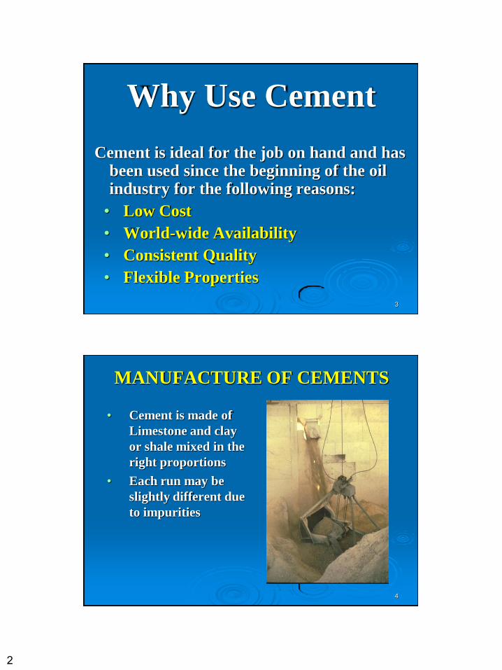
Why Use Cement
Cement is ideal for the job on hand and has been used since the beginning of the oil industry for the following reasons:
• Low Cost
• World-wide Availability
• Consistent Quality
• Flexible Properties
4
MANUFACTURE OF CEMENTS
• Cement is made of
Limestone and clay
or shale mixed in the
right proportions
• Each run may be
slightly different due
to impurities
3
5
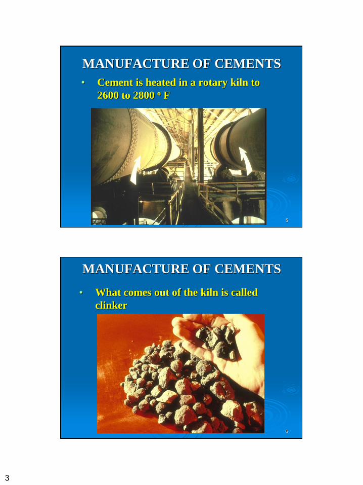
MANUFACTURE OF CEMENTS
• Cement is heated in a rotary kiln to
2600 to 2800 o F
6
MANUFACTURE OF CEMENTS
• What comes out of the kiln is called
clinker
4
7
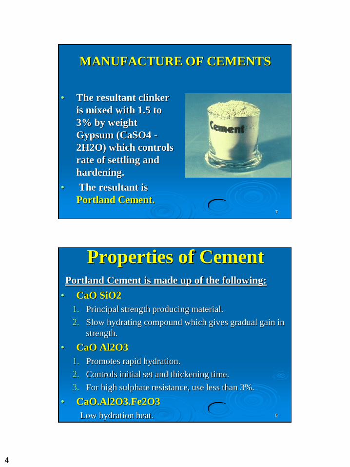
MANUFACTURE OF CEMENTS
• The resultant clinker
is mixed with 1.5 to
3% by weight
Gypsum (CaSO4 -
2H2O) which controls
rate of settling and
hardening.
• The resultant is
Portland Cement.
8
Properties of Cement Portland Cement is made up of the following:
• CaO SiO2
1. Principal strength producing material.
2. Slow hydrating compound which gives gradual gain in
strength.
• CaO Al2O3
1. Promotes rapid hydration.
2. Controls initial set and thickening time.
3. For high sulphate resistance, use less than 3%.
• CaO.Al2O3.Fe2O3
Low hydration heat.
5
9
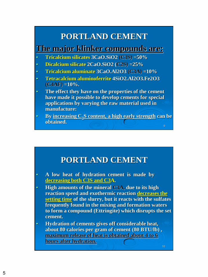
PORTLAND CEMENT
The major klinker compounds are: • Tricalcium silicates 3CaO.SiO2 (C3S) =50%
• Dicalcium silicate 2CaO.SiO2 (C2S) =25%
• Tricalcium aluminate 3CaO.Al2O3 (C3A) =10%
• Tetracalcium aluminoferrite 4SiO2.Al2O3.Fe2O3 (C4AF) =10%.
• The effect they have on the properties of the cement have made it possible to develop cements for special applications by varying the raw material used in manufacture:
• By increasing C3S content, a high early strength can be obtained.
10
PORTLAND CEMENT
• A low heat of hydration cement is made by decreasing both C3S and C3A.
• High amounts of the mineral C3A, due to its high reaction speed and exothermic reaction decreases the setting time of the slurry, but it reacts with the sulfates frequently found in the mixing and formation waters to form a compound (Ettringite) which disrupts the set cement.
• Hydration of cements gives off considerable heat, about 80 calories per gram of cement (80 BTU/lb) , maximum release of heat is obtained about 4 to 6 hours after hydration.
6
11
PORTLAND CEMENT
The principal differences between construction
and oil well cements are that:
(1) no aggregate is added to the oil well cements.
(2) large volumes of water are used in oil well
cements in order to permit the cement slurry to
be pumped.
12
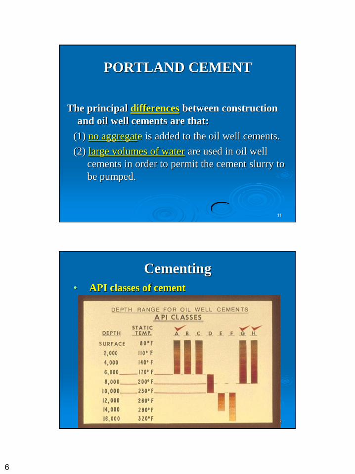
Cementing
• API classes of cement
7
13
Cement Requirements 1. Low viscosity over a sufficient period.
2. Sufficient strength within a reasonably short time in order that the waiting-on-cement time (WOC) can be kept to a minimum. The strength must be sufficient to avoid mechanical failure under prevailing downhole static and dynamic loads.
3. Effective seal between the casing and the formation.
4. Impermeable that fluids cannot flow through it when it has set.
5. Chemically inert to any formations or fluids with which it may come into contact.
6. Stable enough for the length of time it will be in use, which may be many years.
14
Thickening time
• It determines the length of time the slurry can be pumped.
• Thickening time is the time necessary for the slurry consistency to reach 100 poises under simulated bottom hole temperature and pressure.
• Thickening time is affected by the following factors:
• pumping rate: eddies and currents resulting from turbulent flow increases the thickening time.
• amount of cement components that hydrate rapidly (C3A, C3S).
• fineness to which the clinker is ground
8
15
Strength-time requirements
In oil well drilling the cement bulk surrounding the casing is subjected to the following stresses:
• Static stress: shear stresses due to the dead weight of the pipes; compressive stresses due to the action of fluids and formations
• Dynamic stresses resulting from the drilling operation, specially the vibrations of the drill string.
• To withstand these stresses a compressive strength of the order of 500 psi , after 24 hours period, is needed.
16
Perforating qualities
• Ordinary cements when they are completely hardened, fracture excessively when perforated.
• Low strength cements are usually less brittle and have less tendency to shatter upon perforating.
• Shattering of cement is not desired when perforating near an OWC or OGC.
• Additives such as bentonite, pozzolan and latex increase the ductility of set cement.
9
17
Corrosion resistance • Set cement could be penetrated by
corrosive liquids (especially those containing (CO2 or SO4).
• Cement corrosion decreases the final compressive strength render the cement more permeable.
• Reduction of the hardening time improves the cements' resistance to corrosion by corrosive fluids.
18
Bond requirements • For clean surfaces (rock or metal) the bond
increases with time and moderate temperatures.
• Mud cake and dirty casing surfaces reduce markedly the bond between casing (or rocks ) and cement.
• Additives such as salt and fine sand increases the bond between casing and the set cement.
10
19
Cement Additives Various additives are mixed with cement slurry for any
of the following reasons:
• To vary the density between 10.8 to 20 ppg.
• To increase or decrease strength.
• To accelerate or retard setting time.
• To control filtration rate.
• To reduce viscosity.
• To increase corrosion resistance.
• As lost circulation material.
• To improve economics.
20
Cement Additives • Calcium lignosulphate, pozzolan and CMHEC
are considered the most common retarders.
• Calcium lignosulphate could exist in the drilling
fluids where it is usually used as a thinner.
• Calcium chloride is the most common accelerator.
• Salt water slightly reduces the thickening time.
This is of interest in areas where sea water can be
utilized as a mixing water for the slurry.
11
21
Lightweight Additives
• Extra water causes the particles to separate and settle out.
• Bentonite: For each 1% by weight add extra water 3 to 5% by weight.
• Diatomaceous Earth: Similar effects to gel, less strength reduction.
• Perlite: Ground volcanic lava.
• Gilzonite: 25 to 50% with cement.
• Pozzolan: 50-50 with cement gives greater strength and better sulphate resistance.
22
Heavyweight Additives
• Barites (S.G. 4.3 ): 35.03 ppg
• Hematite (S.G. 5.05): 42.12 ppg
• Ottowa Sand (S.G. 2.1): 17.51
ppg
12
23
Accelerators
• Calcium Chloride: 2%
• Sodium Chloride: 2 - 2.5% (retards with
high concentrations)
• Seawater
24
Retarders
• Calcium lignosulphonate for temperatures up to 260°F.
• Calcium lignosulphonate plus organic acid for temperatures above 260°F.
• Diacel LWL, i.e. Carboxymethyl-hydroxyethyl-cellulose ( controls filtration rate).
13
25
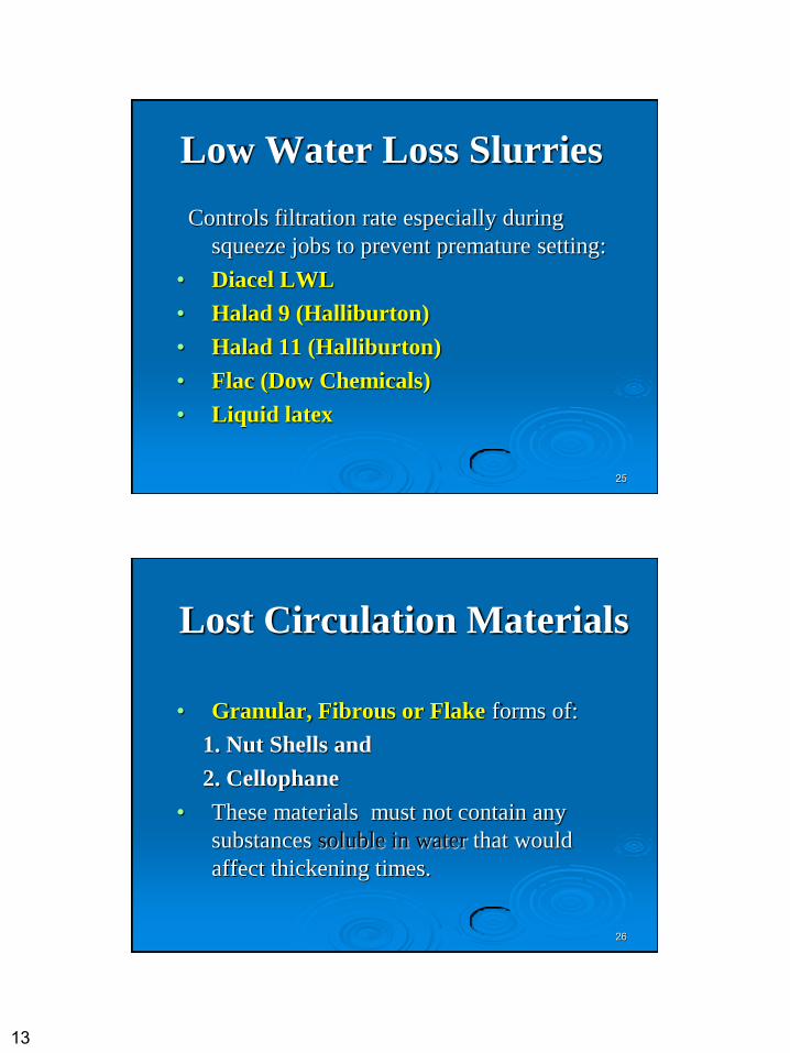
Low Water Loss Slurries
Controls filtration rate especially during
squeeze jobs to prevent premature setting:
• Diacel LWL
• Halad 9 (Halliburton)
• Halad 11 (Halliburton)
• Flac (Dow Chemicals)
• Liquid latex
26
Lost Circulation Materials
• Granular, Fibrous or Flake forms of:
1. Nut Shells and
2. Cellophane
• These materials must not contain any
substances soluble in water that would
affect thickening times.
14
27
28
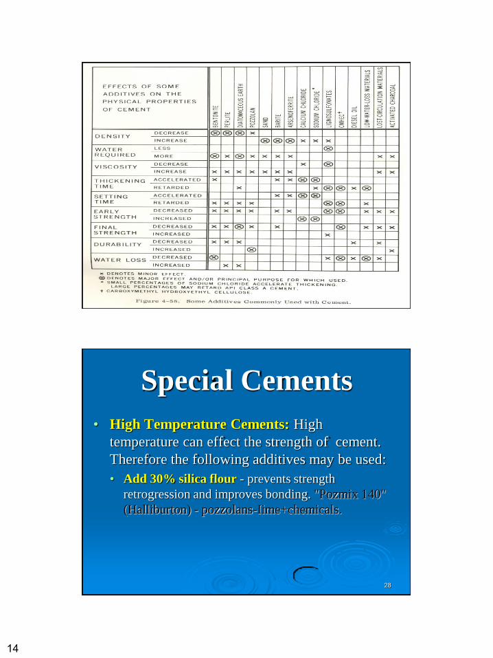
Special Cements
• High Temperature Cements: High
temperature can effect the strength of cement.
Therefore the following additives may be used:
• Add 30% silica flour - prevents strength
retrogression and improves bonding. "Pozmix 140"
(Halliburton) - pozzolans-Iime+chemicals.
15
29
Diesel oil cements
• A portland cement to which a surface active
agent is added, it is designed for mixing with
diesel oil.
• It will not set and harden until it comes in
contact with water.
• It is used for shutting off water production
from the completion interval of a well.
30
Perlite cements • Perlite cements are prepared by adding perlite
to ordinary portland.
• Perlite is a light volcanic ore, when heated to
fusion it gives rise to a very low density
product (13 lb/ft3).
• Bentonite is usually added to perlite cement
slurries to disperse perlite more uniformly
through the mixture.
• Perlite cements are expensive.
16
31
Latex cement • It is composed of latex, cement and water.
• It is used for plug back jobs for water exclusion.
• It is especially resistant to oil and mud contamination.
• It gives a high strength bond with casing and rocks.
32
Pozzolanic cements • Pozzolan (siliceous rocks of volcanic origin) is
added to portland cements or used with lime (lime-
pozzolan cement).
• Pozzolan cements have higher pumpability times
than most conventional cements.
• Pozzolanic cements are light, ductile and they are
proved to be satisfactory deep well cements.
17
33
Considerations after cementing
• After cement hardens, release of pressure on the casing permits it to contract so that the bond with the cement may be loosened.
• Release of pressure on the casing before the cement sets eliminates this problem.
• Bleed off the pressure is made if the back pressure valve in the casing string is holding satisfactorily.
34
Types of Cementing Processes
I. Primary Cementing
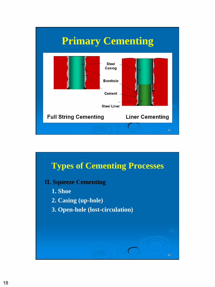
1. Full String
2. Liners
3. Large Pipe
4. Stage
A. Survey and perforate
B. Stage collars
18
35
Primary Cementing
36
Types of Cementing Processes
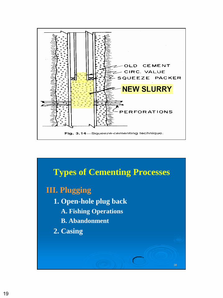
II. Squeeze Cementing
1. Shoe
2. Casing (up-hole)
3. Open-hole (lost-circulation)
19
37
38
Types of Cementing Processes
III. Plugging
1. Open-hole plug back
A. Fishing Operations
B. Abandonment
2. Casing
20
39
Cementing
40
Primary Cementing Practices
• For the best cementing job, concentricity of the
pipe in the wellbore is very important.
• The more concentric the pipe the easier it is to get a
cement uniformly around the pipe, thus the bond
will be complete.
• Without a good bond, the cement job becomes a big
problem involving remedial practices which can be
extremely expensive.
• So why not pay a little extra to ensure the primary
job is done well in the first place.
21
41
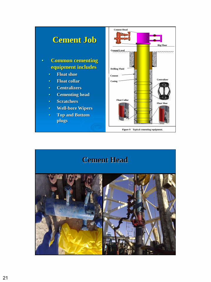
Cement Job
• Common cementing
equipment includes
• Float shoe
• Float collar
• Centralizers
• Cementing head
• Scratchers
• Well-bore Wipers
• Top and Bottom
plugs
Cement Head
Drilling Fluid
Cement
Casing
Float Collar
Float Shoe
Centralizer
Ground Level
Rig Floor
Figure 9 Typical cementing equipment.
42
Cement Head
22
43
44
23
45
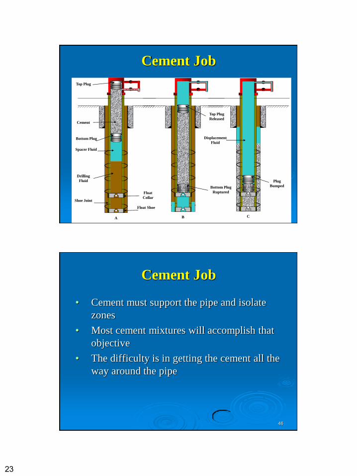
Cement Job
Drilling
Fluid
Spacer Fluid
Bottom Plug
Shoe Joint
Top Plug
Cement
A B C
Float Shoe
Float
Collar
Bottom Plug
Ruptured
Top Plug
Released
Plug
Bumped
Displacement
Fluid
46
Cement Job
• Cement must support the pipe and isolate
zones
• Most cement mixtures will accomplish that
objective
• The difficulty is in getting the cement all the
way around the pipe
24
47
Cement Job
• The industry assumes that if the cement
has a compressive strength of 500 psi it
will support the pipe
• The 500 psi includes a safety factor from
two to five
48
Cement Job
• Cement must also isolate the zone
• Hydraulic bond strengths were tested in
the laboratory and the hydraulic bond
varied with the roughness of the pipe
• Sandblasting the casing was popular for a
while along with Ruff Coat (resin and sand
coated pipe)
25
49
Cement Job
• There was no correlation between
hydraulic bonding and compressive
strength
• The trick is to get the cement all the way
around the pipe
50
Cement Job
• There are a number of things we can do to increase the odds of getting a good cement job
• Centralization of the casing
• Pipe movement - rotation and/or reciprocation
• Drilling fluid condition
• Hole conditions
• Displacement velocity
• Spacer fluids
• Mud - cement density differences
• Contact time
26
51
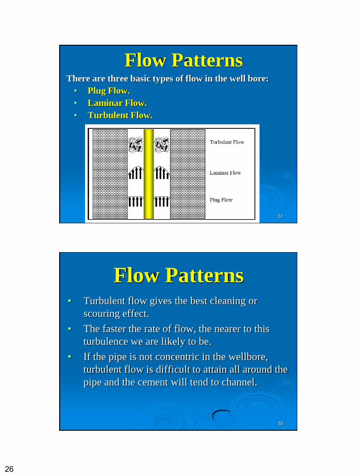
Flow Patterns There are three basic types of flow in the well bore:
• Plug Flow.
• Laminar Flow.
• Turbulent Flow.
52
Flow Patterns • Turbulent flow gives the best cleaning or
scouring effect.
• The faster the rate of flow, the nearer to this
turbulence we are likely to be.
• If the pipe is not concentric in the wellbore,
turbulent flow is difficult to attain all around the
pipe and the cement will tend to channel.
27
53
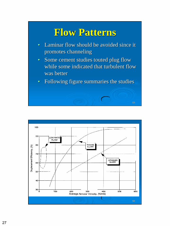
Flow Patterns • Laminar flow should be avoided since it
promotes channeling
• Some cement studies touted plug flow
while some indicated that turbulent flow
was better
• Following figure summaries the studies
54
28
55
Flow Patterns • It is better to pump thin cement slurries
at higher flow rates
• If ECD or hole size prevents higher flow
rates, consider plug flow
• For plug flow, you may have to take the
U-tube effect into account
56
Effective Centralization
• We have know for more than half a century
that centralizing the casing will aid in
getting a good cement job
• For a non-Newtonian fluid, the velocity on
the narrow side of the annulus is slower
than the velocity on the wide side of the
annulus
29
57
Effective Centralization
• This is more critical in deviated wells than in
straight holes.
• We must not use too many as we will be unable
to get the casing into the ground.
• Frictional forces will be greater than the pipe
weight.
58
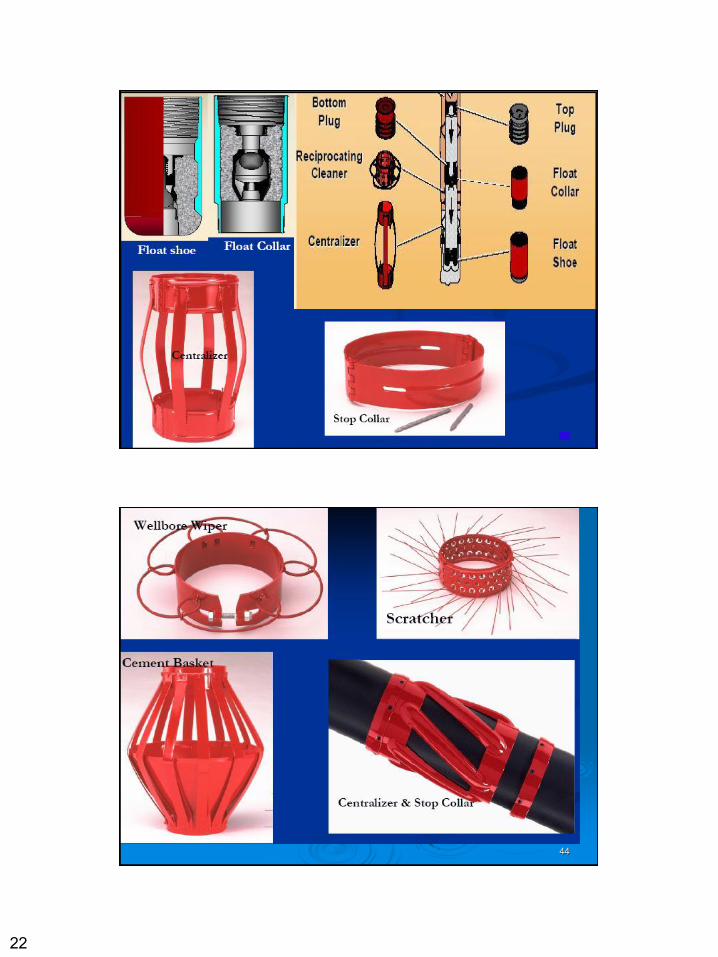
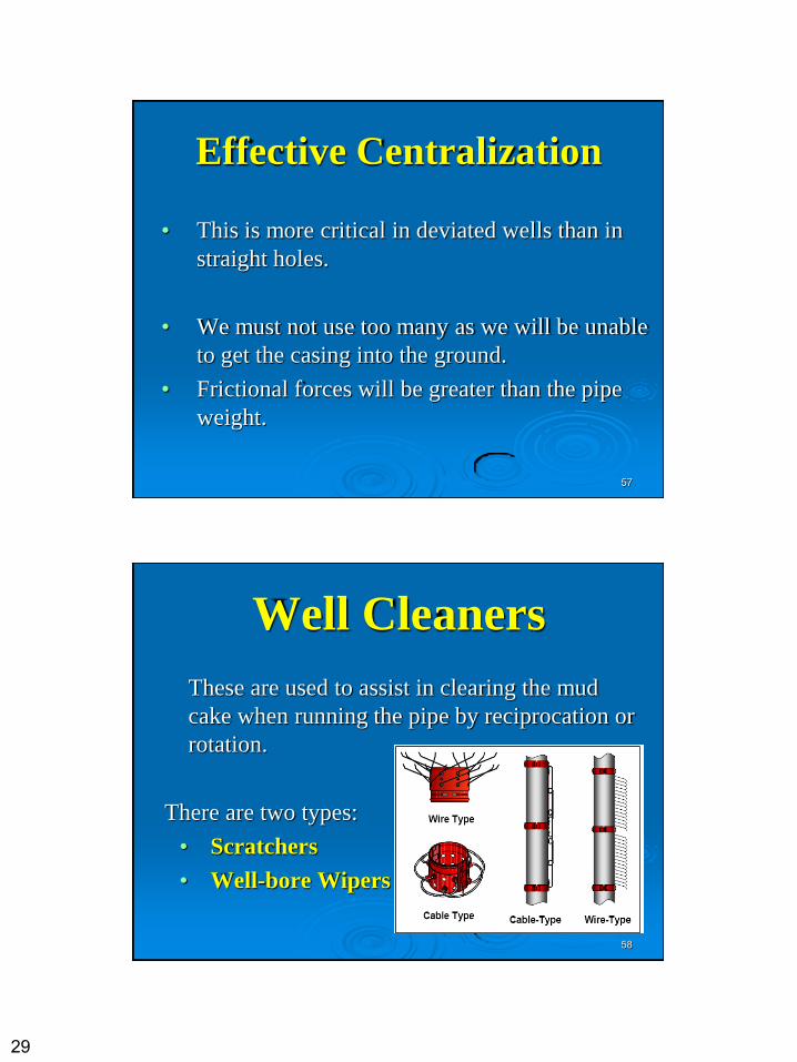
Well Cleaners
These are used to assist in clearing the mud
cake when running the pipe by reciprocation or
rotation.
There are two types:
• Scratchers
• Well-bore Wipers
30
59
Stop Collars
• To secure this 'jewellery' to the pipe 'stop
collars' are sometimes required.
• BEWARE! Too much jewellery can cause
the pipe to 'hang up' in the well bore.
60
Cement Contamination
• To prevent contamination, washes and plugs are
often pumped ahead of slurry.
• The washing water and chemicals assist in
cleaning the wellbore as well as acting as a spacer.
• If too much water is pumped, the hydrostatic
pressure can be dangerously lowered and a kick
may occur up the outside of the casing.
31
61
• The first wiper plug cleans the inside of the casing and landing in the float collar, the diaphragm bursts and allows the cement to be pumped out of the casing.
• The final plug separates the cement from the displacing mud and signals displacement complete, when it 'bumps' on the first plug.
• The casing, from the float to the shoe will be full of cement, if there is any contaminated cement collected by the final plug it will be inside this portion.
• The cement around the shoe joint must be of the best quality.
• In the float and the shoe are ball valves on springs which will not allow the cement to back flow.
62
Evaluation of Cement Job. • In the past, cement jobs have been assumed to be
good, unless there was immediate evidence to the
contrary.
• Now, however, cement evaluation logs are
becoming more and more prevalent.
• CBL (cement bond log) is normally run on
wireline after drilling the next hole section.
• It might be necessary to perforate and squeeze if
these logs show that the primary job is not all that
it might be.
32
63
Stage Cementing
64
Stage Cementing
This technique is used for cementing two or more separate sections behind a casing string. Used for the following reasons:
1. When a long cement column could not be used without breakdown of the formation behind the string.
2. When it is necessary to reduce the pumping
pressure at the surface, especially in cementing
deep wells.
3. When slurries of different compositions are used
for cementing distinct sections.
33
65
Inner String Cementing
• When it is necessary to cement pipe with diameters of 16 inch, 18 inch, 20 inch, or larger, tubing or drill pipe is commonly used as an inner string in the placement of the cement.
• The tubing, or drill string, is stabbed into a specially designed float collar or guide shoe.
• This procedure reduces the cementing time and the volume required to pump the cementing plug.
• It also avoids having to displace a large volume of cement that would be in the large casing if channeling should occur.
66
Deep Well Liner Cementing
• Deep wells usually start with 20 to 30-inch conductor casing and are ultimately completed with 5, 5-1/2 or 7-inch liners.
• In some of the deep wells, it is common to set two liners (a drilling liner and a production liner) before reaching the ultimate drilling objective.
• The wear and tear on the intermediate liner during drilling often requires the setting of a tie-back string before the well is completed.
• The tie-back string stabilizes and reinforces the intermediate liner and intermediate casing, which may have been weakened during the drilling process.
34
67
Plug Back Cementing
68
Plug Back Cementing
Reasons for plugging 1. Zone Isolation
2. Lost Circulation
3. Directional Drilling
4. Abandonment
35
69
Placement Methods
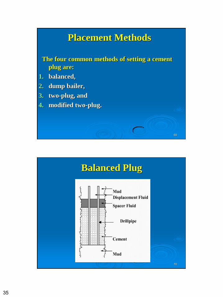
The four common methods of setting a cement
plug are:
1. balanced,
2. dump bailer,
3. two-plug, and
4. modified two-plug.
70
Balanced Plug
36
71
Balanced Plug • The balanced plug method is the one most frequently
used.
• It is a simple method and requires no equipment other than a cementing service unit.
• Placing a desired quantity of slurry into the work string and displacing it near the bottom of the work string.
• Keep displacing until the level of cement outside of the work string balances with the level inside the work string.
• Last of all, you pull the work string up out of the slurry.
• This leaves the cement plug in place.
72
Balanced Plug
• Two disadvantages of the balanced plug method are:
1. mud contamination and
2. movement of the plug.
• Mud contamination is especially possible when you use small quantities of cement.
• The excess cement used when the hole size is uncertain may create fluid loss below the plug and allow the plug to move downward.
37
73
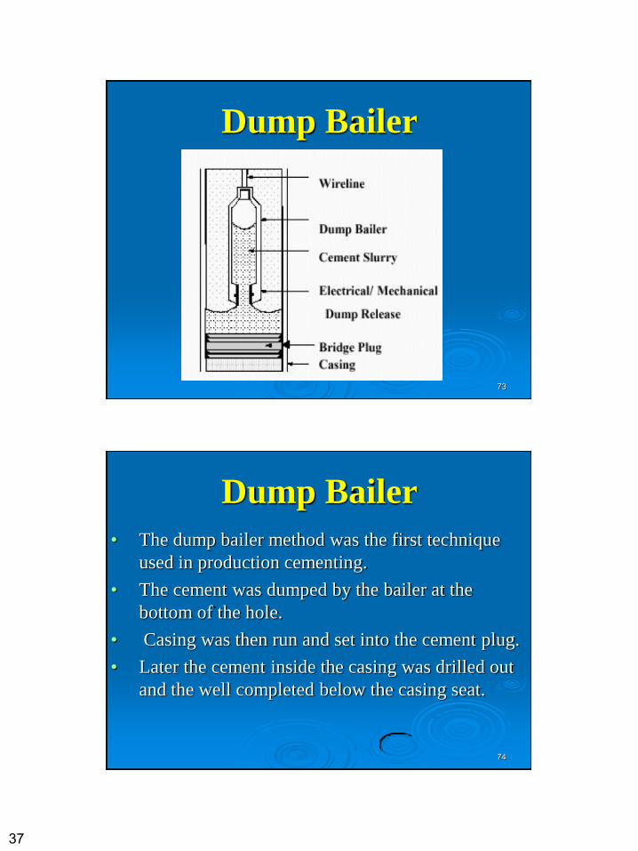
Dump Bailer
74
Dump Bailer
• The dump bailer method was the first technique
used in production cementing.
• The cement was dumped by the bailer at the
bottom of the hole.
• Casing was then run and set into the cement plug.
• Later the cement inside the casing was drilled out
and the well completed below the casing seat.
38
75
Dump Bailer
• Today, the dump bailer method usually involves setting a cement basket, permanent bridge plug, or sand pack below the desired plug location.
• The bailer then dumps the cement above the basket, bridge plug or sand pack.
• The dump bailer method is generally used at shallower depths.
• Present day retarders, however, have increased the depth range to over 12,000 feet.
76
Dump Bailer
• The advantages of this method are: low cost and
depth control since the bailer is run on a
wireline.
• The disadvantages are adapting the method for
setting deep plugs, contaminating the cement, and
the slowness of the method.
39
77
Testing A Cement Plug
• The most common technique used to test a plug is setting
the weight from the workstring onto the top of the plug,
(10000-15000 lb)
• Another method of testing a cement plug involves the use
of drill stem testing tools.
• Run the testing tools and expand the open hole packer as
near to the top of the plug as possible.
• When the tool opens, you can use the hydrostatic loading
of the anchor pipe to determine if the plug will slide down
the hole or if it is still soft.
78
SQUEEZE CEMENTING
40
79
SQUEEZE CEMENTING
• Definition: the process of applying hydraulic
pressure to force or squeeze a cement slurry into a
formation void or against a porous zone.
• It is the most common type of down-hole remedial
cementing.
• Its objective is to obtain a seal between the casing
and the formation.
80
Purposes of squeeze cementing • Control high GOR's. By isolating the oil zone from
an adjacent gas zone.
• To control excessive water or gas. Water or gas
sands can be squeezed off below the oil sand to
help decrease water/oil or gas/oil ratios.
• Independent water or gas zones can usually be
squeezed to eliminate water or gas intrusion.
• To repair casing leaks. Cement can be squeezed
through corrosion holes in casing.
41
81
Purposes of squeeze cementing
• To seal off thief zones or lost-circulation zones.
• To protect against fluid migration into a producing
zone (block squeezing).
• To isolate zone in permanent completions.
• To correct a defective primary cementing job.
• To prevent fluid migration from abandoned zones
or wells.
82
SQUEEZE TERMINOLOGY
• Squeeze Pressure-Squeeze cementing objectives are usually defined by pressure requirements.
• The "high-pressure" technique involves breaking down the formation and pumping cement slurry or cement filtrate into the formation until a specific surface pressure can be maintained without bleed off.
• The 'low-pressure" technique involves placing cement over the interval to be squeezed and applying a pressure sufficient to form a filter cake of dehydrated cement in perforations, channels, or fractures that may be open.
42
83
SQUEEZE TERMINOLOGY
• Block Squeezing - block squeeze is to perforate above and below the pay section and then squeeze cement through the perforations. It is used to isolate the producing zone before completing a well. The technique normally involves two perforating steps, two squeeze steps, and drilling out.
• Breakdown Pressure - Breakdown pressure is the pressure necessary to break down or fracture the formation so that it will accept fluid.
• In high-pressure squeezing, this is the pressure that must be achieved before putting cement slurry or cement filtrate into a formation.
• With the low- pressure technique, a satisfactory squeeze can be performed without breaking down the formation.
84
SQUEEZE TERMINOLOGY
• Fracture Gradient -Fracture gradient is usually defined
as the pressure per foot of depth required to initiate a
fracture. Less pressure is required to extend and prop a
fracture than to create it.
• Bottom-Hole Treating Pressure: It is the pressure
exerted on the formation during a squeeze operation.
• It is the surface pressure plus the hydrostatic pressure of
well fluids minus the frictional pressure.
• To fracture a formation, this pressure must be exceeded.
43
85
SQUEEZE TERMINOLOGY
• Cement Dehydration - The water is squeezed
form the cement slurry and a filter cake of solid
particles forms on the face of the formation.
• If excessive pressure is exerted, the formation will
fracture and some slurry will be forced into the
fractures during the squeeze.
86
Squeeze Methods Techniques
Bradenhead squeeze method • The original method of squeezing was the
bradenhead method, which is accomplished through tubing or drillpipe without the use of a packer.
• A predetermined amount of slurry is mixed and pumped to a specific height outside the tubing or drillpipe.
• The tubing or drillpipe is then pulled out of the slurry and the wellhead is packed off at the surface.
44
87
Bradenhead squeeze method
88
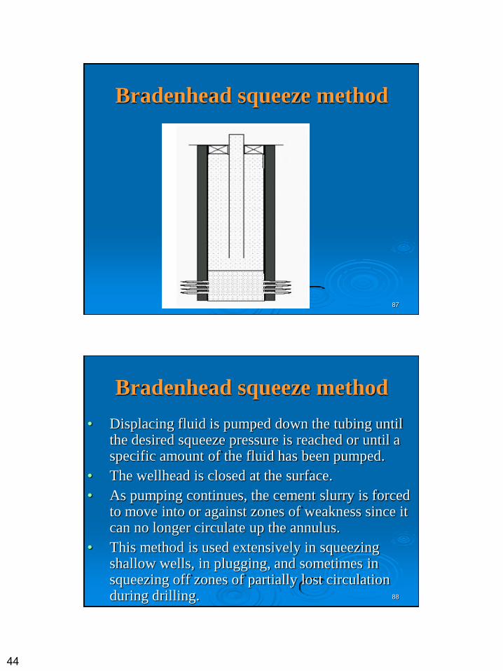
Bradenhead squeeze method
• Displacing fluid is pumped down the tubing until the desired squeeze pressure is reached or until a specific amount of the fluid has been pumped.
• The wellhead is closed at the surface.
• As pumping continues, the cement slurry is forced to move into or against zones of weakness since it can no longer circulate up the annulus.
• This method is used extensively in squeezing shallow wells, in plugging, and sometimes in squeezing off zones of partially lost circulation during drilling.
45
89
Bradenhead squeeze method
• In deeper wells, the cement maybe spotted halfway
down the tubing before the casing valve at the
surface is closed.
• The applicability of bradenhead squeezing is
restricted because the casing must be pressure tight
above the point of squeezing and because
maximum pressures are limited by the burst
strength of casing.
90
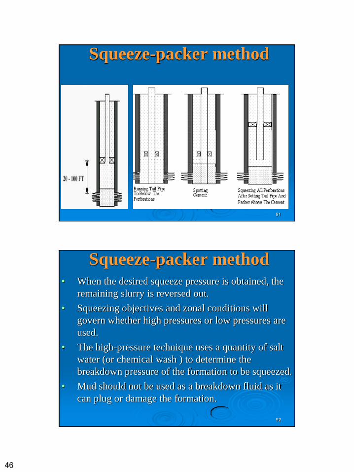
Squeeze-packer method
• The squeeze -packer method uses a retrievable or a non retrievable tool run on tubing to a position near the top of the zone to be squeezed.
• This technique is generally considered superior to the bradenhead method since it confines pressures to a specific point in the hole.
• Before the cement is placed, a pressure test is conducted to determine the formation breakdown pressure.
• The section below the perforations to be squeezed must be isolated with a bridge plug.
46
91
Squeeze-packer method
92
Squeeze-packer method • When the desired squeeze pressure is obtained, the
remaining slurry is reversed out.
• Squeezing objectives and zonal conditions will
govern whether high pressures or low pressures are
used.
• The high-pressure technique uses a quantity of salt
water (or chemical wash ) to determine the
breakdown pressure of the formation to be squeezed.
• Mud should not be used as a breakdown fluid as it
can plug or damage the formation.
47
93
Squeeze-packer method
• The use of squeeze packers makes it possible to apply higher pressure to satisfy down-hole points than can be applied with the bradenhead method.
• The two commonly used packers are the drillable and the retrievable.
• Drillable packers, which are expendable, are left in the well and can be drilled out after the squeeze operation.
• The retrievable packer is rented on a job basis and, after the squeeze job, is removed from the well.
• While each packer has its specific application , the ratio of usage is approximately 40/60
94
SQUEEZE PRESSURE REQUIREMENTS
• After breakdown, a slurry of cement and water
is spotted near the formation and pumped at a low rate.
• As pumping continues, injection pressures begin to build up until surface pressure indicates that either cement dehydration or a squeeze has occurred.
• Pressure is held momentarily on the formation to verify static conditions and then released to determine if the cement will stay in place.
48
95
SQUEEZE PRESSURE REQUIREMENTS
• If the desired squeeze pressure is not obtained, a
hesitation is often employed.
• This method involves mixing one batch of cement
( 30 to 100 sack), placing it against the formation,
waiting at least until the initial set, and repeating
the operation as many times as required.
• The low-pressure technique has become the more
efficient method of squeezing with the
development of controlled-fluid-loss cements and
retrievable packers.
96
SQUEEZING FRACTURED ZONES
• In squeezing fractured limestone and dolomite formations,
greater emphasis must be placed on effectively sealing the fracture network or channel system behind the casing.
• It is necessary to modify the slurry design from that used to squeeze permeable sandstones, where the prime interest is slurry behavior within the perforations.
• In squeezing a fractured carbonate formation it is more important that the cement fill the fracture or channels than that it build up a filter cake.
• Larger volumes of slurry are required than for squeezing permeable sand stone reservoirs.
49
97
Slurry Design • The volume of cement slurry to be squeezed cannot be
controlled precisely, and experience in the vicinity of the
job is the best guide. However, there are some useful
indexes and rules of thumb:
• The volume should not exceed the capacity of the run-in
string.
• Two sacks of cement should be used per foot of perforated
interval.
• The minimum volume should be 100 sk if an injection rate
of 2 bbl/min. can be achieved after break-down; otherwise
it should be 50 sk.
98
Workover fluids • Where well conditions permit and where it is obtainable,
salt water or fresh water is the preferred work-over fluid for both low-pressure and high-pressure squeeze jobs.
• However, even if clean fluids are used and pressures are great enough to fracture the formation , if a well has been perforated in mud, or if perforations have ever been contacted by mud, some mud plugs may remain and more than one squeeze job may be needed.
• Should squeezing be necessary in mud filled or partially plugged perforations, one of the best ways to insure a uniform deposit of cement is to run a weak hydrochloric or acetic acid solution ahead of the cement. The acid shrinks the clay particles and allows the cement slurry to penetrate farther.
50
99
TESTING SQUEEZE JOBS
• The apparent success or failure of a squeeze job should be
confirmed by applying pressure to the set cement.
• Although squeeze jobs are most commonly tested by-
pump pressure, a better way is to create a pressure
differential in the wellbore.
• This can be accomplished by swabbing, by artificially
lifting fluid from the well, or by circulating oil or a lighter
fluid down the tubing and closing the circulating ports
above the packer.
• This differential pressure should not exceed the drawdown
expected in the well when it is put on production.
100
END