cementite - phase-trans.msm.cam.ac.uk · full critical review cementite h. k. d. h. bhadeshia...
TRANSCRIPT

FULL CRITICAL REVIEW
CementiteH. K. D. H. Bhadeshia
Materials Science and Metallurgy, University of Cambridge, Cambridge, UK
ABSTRACTCementite occurs in steels, in meteorites, possibly at the core of the Earth and has uses inits pure form. It’s composition can deviate from Fe3C, but not by much because the Fe–Cbond contributes to its cohesion. Its crystallographic unit cell is orthorhombic andprimitive, with large lattice parameters, explaining its hardness. Many of its propertiesare anisotropic. Its single-crystal elastic properties have been investigated usingfirst-principles calculations and by clever experiments. The iron atoms in the cell occupytwo types of positions with different point symmetries; the four carbon atoms lodgewithin prismatic interstices. The structure can develop defects such as dislocations, faultsand vacancies. Cementite is metallic and ferromagnetic with a Curie temperature ofabout 187◦C. When alloyed, metallic solutes substitute on to the iron sites; smalleratoms such as boron replace carbon at interstitial sites. This review focuses on cementiteas a single phase.
ARTICLE HISTORYReceived 5 September 2018Accepted 17 December 2018
KEYWORDSCementite; iron carbides;crystal structure; stability;properties
1. Introduction
In its crystalline, liquid and glassy states, iron has anaffinity for carbon in its many forms, whether toform a solution over a wide range of compositions,or in the form of compounds with narrowly definedcompositions, such as cementite. It is possible, there-fore, to find equilibria between iron and graphite,iron and diamond and iron and cementite, representedconventionally by the respective binary, two-phase dia-grams. Such diagrams identify domains, for example,in temperature and composition space, where either asingle phase or a combination of phases is stable. How-ever, the term stable is a tenuous concept because theremight be something else also consisting of Fe and C,which may be more stable. Instead of considering justtwo phases together, if we now put iron, graphite andcementite in mutual contact at ambient pressure thenthe cementite eventually must give way to the morestable equilibrium between graphite and iron. All equi-libria in this sense are metastable; even the constituentsof atoms will all decay eventually if the Universe keepson expanding.
Nevertheless, some 50 million tonnes of cementite isproduced annually within about 1.6 billion tonnes ofsteel, adding enormously to the quality of life. This isbecause it is hard at ambient temperature, as we shallsee, due to its crystal structure that has a much lowersymmetry than all the forms in which the iron occurs.Its metastability mostly does not matter over the time
scale and conditions of normal life. The longestsingle-span suspension bridge in the world, the Aka-shi-Kaikyo Bridge, utilises exceptionally strong ropesto suspend the deck. The bridge connects Kobe withAwaji Island and has a span of 1.9 km between thetowers. There is enough steel wire used in the bridgeto circle the earth seven times, with the bridge beingdesigned to withstand an earthquake of Richter 8.5magnitude. The bridge represents a magnificient tri-umph of engineering and steel containing substantialquantities of cementite, without which the ropeswould be nothing short of feeble (Figure 1).
In spite of its metastability, we shall see that cemen-tite is found in meteorites that have cooled at a fewdegrees per million years, and within diamondsfound deep in the bowels of the Earth. It perhaps hasplayed a seminal role in the genesis of carbon nano-tubes from gaseous reactions. There is fledgling workto indicate that nanoparticles of cementite may havea useful purpose in biomedicine for the site-specificdelivery of healing drugs.
This is a review about cementite as a phase in itsown right. How was its chemical composition estab-lished given that the nature of carbon inside steelcould not have been understood in the very earlydays of metallography? In 1878, Müller [1] dissolvedsome steel in dilute sulphuric acid to leave behind ablack residue which when analysed contained 6.01–7.38 wt-% carbon. Müller referred to this as
© 2019 The Author(s). Published by Informa UK Limited, trading as Taylor & Francis GroupThis is an Open Access article distributed under the terms of the Creative Commons Attribution-NonCommercial-NoDerivatives License (http://creativecommons.org/licenses/by-nc-nd/4.0/), which permits non-commercial re-use, distribution, and reproduction in any medium, provided the original work is properly cited, and is not altered, transformed, orbuilt upon in any way.
CONTACT H. K. D. H. Bhadeshia [email protected] Materials Science and Metallurgy, University of Cambridge, 27 Charles Babbage Road, CambridgeCB3 0FS, UK
INTERNATIONAL MATERIALS REVIEWS2020, VOL. 65, NO. 1, 1–27https://doi.org/10.1080/09506608.2018.1560984

amorphous iron. Comprehensive experiments doneindependently by Abel around 1883 were publishedin 1885 in a report, on the state of carbon withinsteel [2]. This confirmed ‘the correctness of the con-clusions based on earlier experiments, that the carbonin cold-rollled steel exists in the form of a definiteiron carbide, approximating the formula Fe3C or to amultiple of that formula’. In the same experiments,hardened steel (presumably martensitic) ‘appeared tohave the effect of preventing or arresting the separationof carbon, as a definite carbide’.
The name has its origins in the theory of Osmondand Werth, in which the structure of solidified steelconsists of a kind of cellular tissue, the iron constitutingthe nucleus and the carbide the envelope of the cells1
[3,4]. The carbide was therefore envisioned to cementthe iron.
In mineralogy, the carbide is known as cohenite (Fe,Ni,Co)3C, after the German mineralogist Emil Cohen,who was investigating material of meteoric origin. Theimpact of carbon-containing meteorites with themoon is speculated to lead to a reduction of theiron-containing minerals on its surface; the resultingreaction with the carbonaceous gases generated bythe impact produces cementite [5]. Cementite is infact of much wider interest than in metallurgy alone,within subjects spanning from astrophysics, planetaryscience, Lunar processes, and biomedicine to namebut a few.
Cementite often is said to be metastable withrespect to graphite. However, as shown in Figure 2,pure cementite when allowed to coexist only withgraphite, is stable in the presence of graphite, pre-sumably because the iron does not dissolve in graph-ite. When ferrite on the other hand is allowed tocoexist with cementite and graphite, the stable
mixture at equilibrium becomes ferrite and graphite.These calculations are consistent with observationson carburised iron, where the cementite in contactwith ferrite decomposes more rapidly to graphiteduring heat treatment, than cementite that is lodgedwithin coke [6]. Nanoparticles of cementite that aresurrounded by a thin shell of carbon remain stableas cementite during heat treatment at 700◦C for 90min at ambient pressure [7]. This might contradictthe observation of cementite, rather than graphite,in meteorites that are iron-rich. However, meteoritesare created when under large pressures; cementitethen becomes stable because there is a prominentreduction in molar volume (≈ 14%) when graphitechanges into cementite [8]. However, it is not clearwhether the meteoric material is under high press-ures during cooling through the temperatureswhere cementite precipitates (it would be necessaryfor the meteorite to have been enclosed within amuch larger cosmic body). At the low pressuresassociated with the size of typical meteorites, thecementite should decompose during cooling, but itdoes not do so. Meteorites cool at extraordinarilyslow rates, some 10 K per million years, so any crys-tal will tend to grow with a high state of perfection.In the absence of heterogeneous nucleation sites,the genesis of graphite would be retarded, leavingopen the possibility that the cementite observed isin fact metastable, not stabilised by pressure [9].Cementite particles have also been found in deeply-mined diamonds observed at ambient pressure, thatwill have experienced some 50 GPa of pressureduring their formation [10]; this cementite is alsolikely to be metastable.
2. Stoichiometry of cementite
The carbon atoms in cementite are located in intersti-tial sites [12,13]; any deficit from the 3:1 Fe:C atomratio is attributed to interstitial vacancies that normallyare occupied by carbon atoms, as inferred from latticeparameter changes [14]. The specific volume of cemen-tite that is in equilibrium with ferrite at ambient temp-erature is found to be greater than that calculated usingits measured lattice parameters, indicating vacant car-bon sites, i.e. a deviation from the stoichiometric com-position [15]. Similar conclusions have been reachedby measuring phase fractions and lattice parametersin rapidly cooled Fe–C alloys containing large carbonconcentrations [16]. Indeed, the detailed changes inthree lattice parameters of cementite quenched fromdifferent temperatures have been shown to be consist-ent qualitatively with corresponding parameters calcu-lated using ab initio methods where carbon-specificsites are left unoccupied [17].
Figure 1. The Akashi-Kaikyo Bridge in Japan, the longestsingle-span suspension bridge, which relies on huge cablesmade from pearlitic steel. Photograph courtesy of ProfessorNobutaka Yurioka.
1‘une sorte de tissu cellulaire, le fer constituant le noyau et le carbure l’enveloppe des cellules’
2 H. K. D. H. BHADESHIA
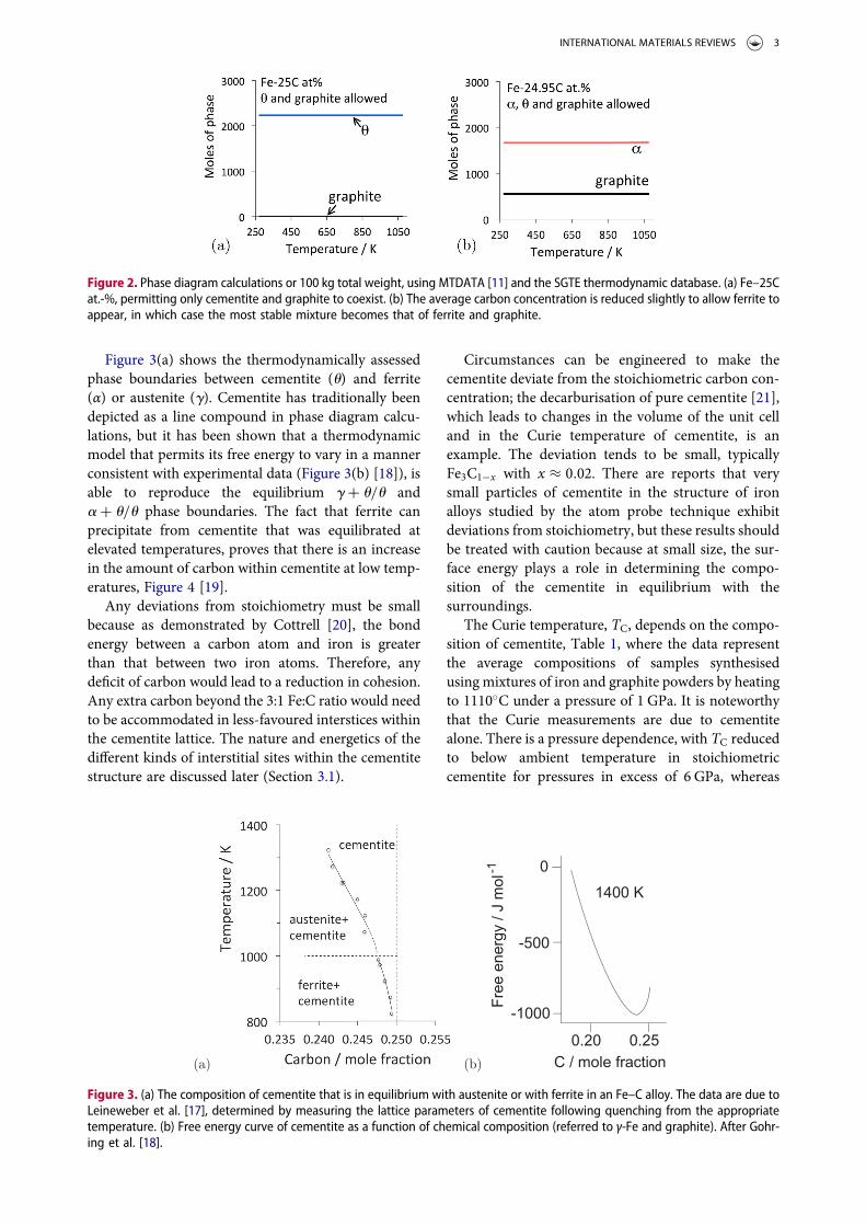
Figure 3(a) shows the thermodynamically assessedphase boundaries between cementite (u) and ferrite(α) or austenite (g). Cementite has traditionally beendepicted as a line compound in phase diagram calcu-lations, but it has been shown that a thermodynamicmodel that permits its free energy to vary in a mannerconsistent with experimental data (Figure 3(b) [18]), isable to reproduce the equilibrium g + u/u anda + u/u phase boundaries. The fact that ferrite canprecipitate from cementite that was equilibrated atelevated temperatures, proves that there is an increasein the amount of carbon within cementite at low temp-eratures, Figure 4 [19].
Any deviations from stoichiometry must be smallbecause as demonstrated by Cottrell [20], the bondenergy between a carbon atom and iron is greaterthan that between two iron atoms. Therefore, anydeficit of carbon would lead to a reduction in cohesion.Any extra carbon beyond the 3:1 Fe:C ratio would needto be accommodated in less-favoured interstices withinthe cementite lattice. The nature and energetics of thedifferent kinds of interstitial sites within the cementitestructure are discussed later (Section 3.1).
Circumstances can be engineered to make thecementite deviate from the stoichiometric carbon con-centration; the decarburisation of pure cementite [21],which leads to changes in the volume of the unit celland in the Curie temperature of cementite, is anexample. The deviation tends to be small, typicallyFe3C1−x with x ≈ 0.02. There are reports that verysmall particles of cementite in the structure of ironalloys studied by the atom probe technique exhibitdeviations from stoichiometry, but these results shouldbe treated with caution because at small size, the sur-face energy plays a role in determining the compo-sition of the cementite in equilibrium with thesurroundings.
The Curie temperature, TC, depends on the compo-sition of cementite, Table 1, where the data representthe average compositions of samples synthesisedusing mixtures of iron and graphite powders by heatingto 1110◦C under a pressure of 1 GPa. It is noteworthythat the Curie measurements are due to cementitealone. There is a pressure dependence, with TC reducedto below ambient temperature in stoichiometriccementite for pressures in excess of 6 GPa, whereas
Figure 2. Phase diagram calculations or 100 kg total weight, using MTDATA [11] and the SGTE thermodynamic database. (a) Fe–25Cat.-%, permitting only cementite and graphite to coexist. (b) The average carbon concentration is reduced slightly to allow ferrite toappear, in which case the most stable mixture becomes that of ferrite and graphite.
Figure 3. (a) The composition of cementite that is in equilibrium with austenite or with ferrite in an Fe–C alloy. The data are due toLeineweber et al. [17], determined by measuring the lattice parameters of cementite following quenching from the appropriatetemperature. (b) Free energy curve of cementite as a function of chemical composition (referred to γ-Fe and graphite). After Gohr-ing et al. [18].
INTERNATIONAL MATERIALS REVIEWS 3

carbon-rich cementite remains ferromagnetic to higherpressures ( ≈ 7 GPa).
An interpretation [24] of the change in magneticproperties as a function of pressure attributes thephenomenon to the volume-dependent two-state the-ory for the high magnetic moment to small-volumelow moment transition. Using an X-ray techniqueand diamond anvil equipment, it has been determinedexperimentally that the loss of ferromagnetism occursat about 10 GPa. The change in volume required toinduce the magnetic transition is about 5% [24,25].
The atom probe permits the composition of cemen-tite to be measured directly using time-of-flight massspectroscopy. There are, nevertheless, difficulties inmeasuring the carbon concentration of cementite[26]. It has not yet been possible to demonstrate
small deviations from stoichiometry using such high-resolution methods. However, using conventionalatom probe field ion microscopy, extremely small(4 nm) cementite particles in severely deformed mix-tures of ferrite and cementite have been shown to con-tain only 16 at.-% of carbon, a concentration thatrecovers to the 25 at.-% when the mixture is annealedto reduce the defect density and coarsen the cementite[27]. It is argued that the deformation introducesdefects such as vacancies into the cementite, leadingto the reduction in carbon concentration. However, itis important to note that the particles containingsuch a large deviation from stoichiometry were notproven to retain the orthorhombic crystal structure.
One study, based on neutron diffraction intensitiesmeasured over at temperatures ranging from ambientto 800◦C in a eutectoid steel, claims huge deviationsof the carbon concentration from the stoichiometricratio in undeformed cementite [28]; the result is unli-kely given the extensive experimental data that existin the literature for the Fe3C composition of this kindof cementite. Zhukov and co-workers have claimed,on the basis of lattice parameter measurements ormetallographic observations, that the temperaturefrom which a cast iron is quenched can alter the stoi-chiometry of cementite, but the results do not accountfor the partitioning of other solutes between thecementite and other phases [29,30].
3. Crystal structure of cementite
Cementite has an orthorhombic unit cell and the com-mon convention is to set the order of the lattice par-ameters as a = 0.50837 nm, b = 0.67475 nm andc = 0.45165 nm. There are 12 atoms of iron in theunit cell and 4 of carbon, as illustrated in Figure 5.Four of the iron atoms are located on mirror planes,whereas the other eight are at general positions(point symmetry 1).
The lattice type is primitive (P). There are n-glideplanes normal to the x-axis, at 1
4 x and 34 x involving
translations of (b/2) + (c/2). There are mirror planesnormal to the y-axis and a-glide planes normal to thez-axis, at heights 1
4 z and34 z with fractional translations
of a/2 parallel to the x-axis. The space group symbol istherefore Pnma [31]. Each Wyckoff position in thisspace group is labelled with a letter (Table 2); thus,the eight iron atoms in general positions are labelledwith the letter ‘d’, and the remaining four on mirrorplanes with the letter ‘c’; the number preceding theletter, for example, the ‘8’ in 8d, denotes the numberof equivalent positions in the cell.2
Figure 4. Precipitation of fine platelets of ferrite from cemen-tite. Reproduced with permission of Taylor and Francis from[19].
Table 1. Ambient pressure measurements of the Curietemperature of cementite as a function of its carbonconcentration. Data from Walker et al. [22], determined bymaking cementite as a part of a transformer. Choe [23]reports a somewhat lower Tc of 167.6◦C determined using asuperconducting quantum interference magnetometer forambient pressure.Phases present Nominal at% C TC / ◦C
cementite, graphite 26 174cementite 25 186cementite 25 187cementite 23 173cementite, Fe 22 173
2The space group Pnma has been reported to be inconsistent with cementite that has been annealed at a high temperature, based on a comparison ofexperimental electron energy-loss fine structure spectra with calculations. A technique such as this gives qualitative information about the local atomicconfigurations within the structure [32]. However, Mossbäuer and X-ray diffraction experiments show that the correct space group for annealed cementiteis in fact Pnma [33].
4 H. K. D. H. BHADESHIA

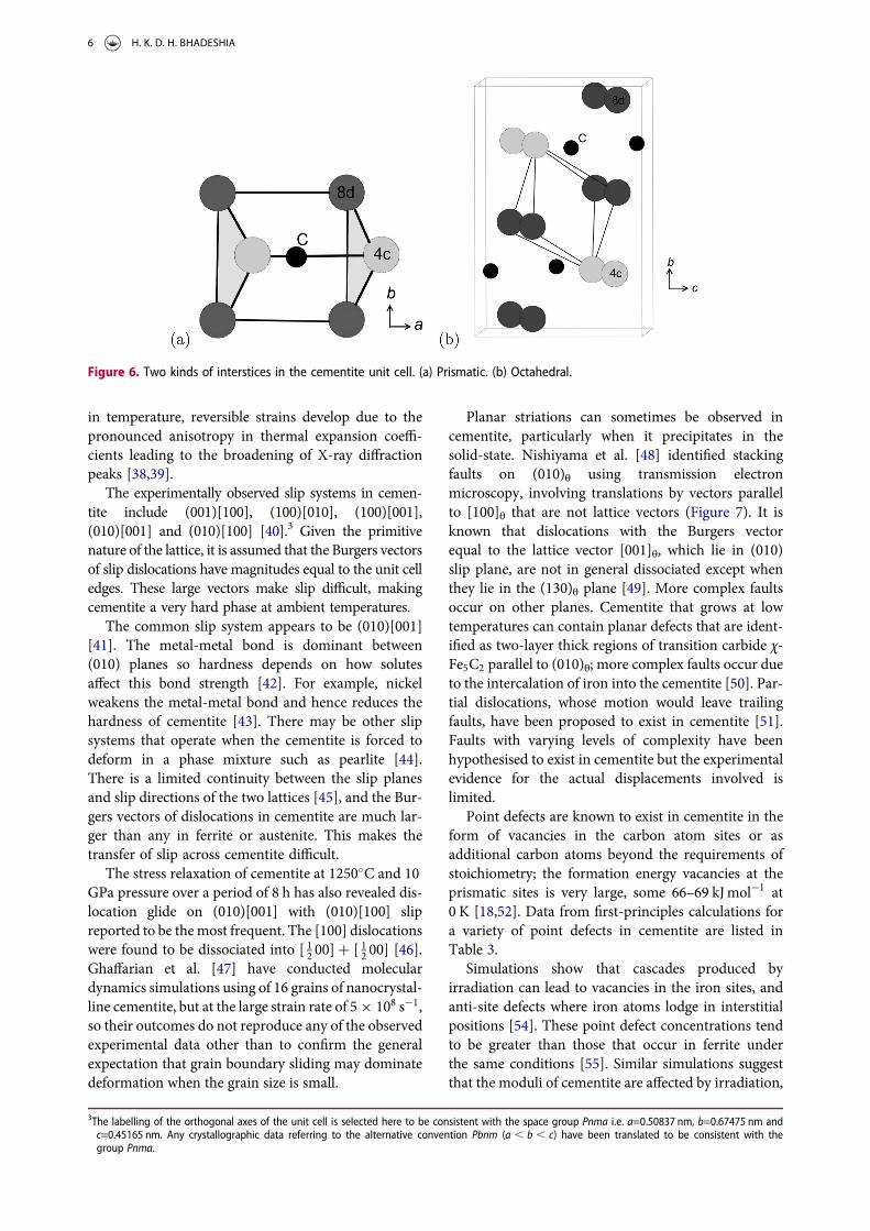
3.1. Types of interstitial sites
There are prismatic, octahedral and three kinds of tet-rahedral interstices in the cementite unit cell; if thespace within each is defined from the centre of theinterstice to the boundary of the nearest iron atom,then the sizes are 0.71, 0.53, 0.34, 0.26 and 0.28 Å[34]. The centres of the prismatic interstices lie on mir-ror planes so there are four per cell (4c, Table 2) and
they all are filled with carbon atoms in the stoichio-metric form of cementite [13]. The smaller octahedralinterstices, of which there are four per cell (4a, Table 2),are empty in pure cementite unless the carbon concen-tration exceeds 25 at.-%, and the tetrahedral intersticesare too small to be occupied by carbon. When hydro-gen enters the cementite lattice, it locates in the octa-hedral [35] interstices because the prismatic ones areoccupied by carbon (Figure 6).
3.2. Structural defects and deformation
Given the orthorhombic structure, the elastic moduli ofcementite vary with the direction within the crystal[36]. The shear modulus C44 is exceptionally small,some two times smaller than the corresponding termfor aluminium. Nevertheless, the cementite has anexceptionally large ideal shear strength because elasticdeformation reduces its symmetry from orthorhombicto monoclinic (space group P21/c), with an accompa-nying increase in three-dimensional covalent bondingthat stiffens the material [37]. Thermal expansion is afunction of crystallographic orientation; when cemen-tite in its polycrystalline state is subjected to a change
Figure 5. The crystal structure of cementite, consisting of 12 iron atoms (large) and 4 carbon atoms (small, hatched pattern). Thefractional z coordinates of the atoms are marked. Notice that four of the iron atoms are located on mirror planes, whereas the othersare at general locations where the only point symmetry is a monad. The pleated layers parallel to (100) are in . . . ABABAB . . . stack-ing with carbon atoms occupying interstitial positions at the folds within the pleats, with all carbon atoms located on the mirrorplanes. There are four Fe3C formula units within a given cell.
Table 2. Wyckoff positions for space group Pnma.Multiplicity Wyckoff Site Coordinates
letter symmetry
8 d 1 (x, y, z) (− x + 12 ,− y, z + 1
2 )
(− x, y + 12 ,− z)
(x + 12 ,− y + 1
2 ,− z + 12 )
(− x,− y,− z) (x + 12 , y,− z + 1
2 )
(x,− y + 12 , z)
(− x + 12 , y +
12 , z +
12 )
4 c .m. (x, 14 , z) (− x + 12 ,
34 , z +
12 )
(− x, 34 ,− z) (x + 12 ,
14 ,− z + 1
2 )
4 b −1 (0, 0, 12 ) (12 , 0, 0) (0,
12 ,
12 ) (
12 ,
12 , 0)
4 a −1 (0, 0, 0) ( 12 , 0,12 ) (0,
12 , 0) (
12 ,
12 ,
12 )
Note: Table of space group symbols, July 2018, http://www.cryst.ehu.es/cgi-bin/cryst/programs/nph-wp-list.
INTERNATIONAL MATERIALS REVIEWS 5
in temperature, reversible strains develop due to thepronounced anisotropy in thermal expansion coeffi-cients leading to the broadening of X-ray diffractionpeaks [38,39].
The experimentally observed slip systems in cemen-tite include (001)[100], (100)[010], (100)[001],(010)[001] and (010)[100] [40].3 Given the primitivenature of the lattice, it is assumed that the Burgers vectorsof slip dislocations have magnitudes equal to the unit celledges. These large vectors make slip difficult, makingcementite a very hard phase at ambient temperatures.
The common slip system appears to be (010)[001][41]. The metal-metal bond is dominant between(010) planes so hardness depends on how solutesaffect this bond strength [42]. For example, nickelweakens the metal-metal bond and hence reduces thehardness of cementite [43]. There may be other slipsystems that operate when the cementite is forced todeform in a phase mixture such as pearlite [44].There is a limited continuity between the slip planesand slip directions of the two lattices [45], and the Bur-gers vectors of dislocations in cementite are much lar-ger than any in ferrite or austenite. This makes thetransfer of slip across cementite difficult.
The stress relaxation of cementite at 1250◦C and 10GPa pressure over a period of 8 h has also revealed dis-location glide on (010)[001] with (010)[100] slipreported to be themost frequent. The [100] dislocationswere found to be dissociated into [ 12 00] + [ 12 00] [46].Ghaffarian et al. [47] have conducted moleculardynamics simulations using of 16 grains of nanocrystal-line cementite, but at the large strain rate of 5 × 10⁸ s−1,so their outcomes do not reproduce any of the observedexperimental data other than to confirm the generalexpectation that grain boundary sliding may dominatedeformation when the grain size is small.
Planar striations can sometimes be observed incementite, particularly when it precipitates in thesolid-state. Nishiyama et al. [48] identified stackingfaults on (010)θ using transmission electronmicroscopy, involving translations by vectors parallelto [100]θ that are not lattice vectors (Figure 7). It isknown that dislocations with the Burgers vectorequal to the lattice vector [001]θ, which lie in (010)slip plane, are not in general dissociated except whenthey lie in the (130)θ plane [49]. More complex faultsoccur on other planes. Cementite that grows at lowtemperatures can contain planar defects that are ident-ified as two-layer thick regions of transition carbide χ-Fe5C2 parallel to (010)θ; more complex faults occur dueto the intercalation of iron into the cementite [50]. Par-tial dislocations, whose motion would leave trailingfaults, have been proposed to exist in cementite [51].Faults with varying levels of complexity have beenhypothesised to exist in cementite but the experimentalevidence for the actual displacements involved islimited.
Point defects are known to exist in cementite in theform of vacancies in the carbon atom sites or asadditional carbon atoms beyond the requirements ofstoichiometry; the formation energy vacancies at theprismatic sites is very large, some 66–69 kJmol−1 at0 K [18,52]. Data from first-principles calculations fora variety of point defects in cementite are listed inTable 3.
Simulations show that cascades produced byirradiation can lead to vacancies in the iron sites, andanti-site defects where iron atoms lodge in interstitialpositions [54]. These point defect concentrations tendto be greater than those that occur in ferrite underthe same conditions [55]. Similar simulations suggestthat the moduli of cementite are affected by irradiation,
Figure 6. Two kinds of interstices in the cementite unit cell. (a) Prismatic. (b) Octahedral.
3The labelling of the orthogonal axes of the unit cell is selected here to be consistent with the space group Pnma i.e. a=0.50837 nm, b=0.67475 nm andc=0.45165 nm. Any crystallographic data referring to the alternative convention Pbnm (a , b , c) have been translated to be consistent with thegroup Pnma.
6 H. K. D. H. BHADESHIA

but the lattice parameters used do not seem to be cor-rect [56].
3.3. Hexagonal cementite
A hexagonal form of cementite (Fe3C) has been dis-cussed in the literature, a form less stable than theorthorhombic variety. There is a dearth of experimen-tal evidence and confusion about the actual structureand its chemical composition. Nagakura [57] usingelectron diffraction concludes that the space group isP6322 with lattice parameters a = 0.4767 nm and c =0.4354 nm, as illustrated in Figure 8; although thestructure selected is consistent with the compositionFe3C, the carbon concentration could not be measuredwith the techniques used.
The original structure proposed by Jack [58,59] wasrather different than that of Nagakura, with the ironatoms in a hexagonal close-packed arrangement andcarbon atoms in octahedral interstitial sites, withchemical composition FexC, where x = 2.4−3 and lat-tice parameters a = 0.273 nm, c = 0.433 nm.
It is not clear whether a hexagonal form of cementitewith a composition Fe3C actually exists. There are
theoretical calculations associated with the phase,based on empirical methods or first principles[60,61]. Electron diffraction patterns from interplane-tary dust particles have been identified with Nagakura’sindexing of hexagonal cementite, although the chemi-cal composition or stoichiometry of the particlesremain undetermined and the same paper sometimesconfuses the Nakagura and Jack structures in the dis-cussion of the cementite [62]. A recent study has
Figure 7. Creation of a stacking fault on (010)θ by a partial displacement parallel to [100]θ that does not recreate the lattice. Carbonatoms have been omitted for clarity. (a) Unfaulted structure. (b) Faulted structure. Adapted from [48].
Table 3. Calculated formation energies for point defects incementite, referred to ferromagnetic bcc iron and diamondas the reference states. Data from the 128 atom simulationsby Jiang et al. [53]. The mole fraction of carbon in cementiteis denoted x. For example, placing an iron atom in aprismatic interstice leads to a carbon concentration that isless than 25 at.-%.
DefectFormation energy per defect /
kJ mol−1x / molefraction
Fe vacancy, 4c site 160 . 0.25Fe vacancy, 8d site 140 . 0.25C vacancy in prismaticinterstice
61 , 0.25
C in Fe-4c site 358 . 0.25C in Fe-8d site 273 . 0.25Fe in prismatic interstice 256 , 0.25C in octahedral interstice 71 . 0.25Fe in octahedralinterstice
511 , 0.25
Figure 8. Projection of the possible crystal structure of the hex-agonal form of cementite, using the parameters and symmetryproposed by Nagakura [57]. The fractional z-coordinates ofatoms not located at z = 0,1 are marked. The carbon atoms(hatched) are located in a third of the octahedral intersticesformed by the iron atoms.
INTERNATIONAL MATERIALS REVIEWS 7

claimed that a large fraction of the cementite present ina eutectic mixture with ferrite is hexagonal cementite,on the basis of electron back scattered diffraction[63]. However, their independent X-ray diffractiondata do not show two forms of cementite, only theorthorhombic variety.
4. Magnetic properties
Cementite at ambient pressure and room temperatureis a metallic ferromagnet that becomes paramagneticbeyond the Curie temperature TC of 186◦C (Table 1);TC has been reported to be 208◦C [64] but based onchanges in thermal expansivity that may not havesufficient resolution. The very first measurement wasby Wologdine in 1909 [65], in which particles ofcementite suspended between magnetic poles wereseen to collapse as the temperature was increased, giv-ing TC = 180◦C. Smith in 1911 indicated changes inmagnetometer readings due to cementite containedin steel to be between 180 and 250◦C, claiming thatactual Curie temperature to be around 240◦C [66].Honda in 1915 put this value at 210◦C [67].
The calculated magnetisation of cementite as a func-tion of temperature is illustrated in Figure 9 [68], wherethe average magnetisation at 0 K is about 1.86mB.There are a number of calculations of the local mag-netic moments on the four iron atoms located on mir-ror planes (4c) and at the eight located at generalpositions (8d), giving estimates within the ranges1.92–2.01 and 1.74–1.957mB, respectively, [68–71] at0 K. The ranges quoted primarily arise because the esti-mation of the local magnetic moment depends on thesize of the region (‘muffin tin’) over which the momentis calculated, and there may be differences in numericalaccuracies of the methods used; the total magneticmoment of the unit cell which sums over the entireregion is therefore essentially identical in the varietyof calculations available [72].
There is a transition from ferromagnetic to non-magnetic states at 25 GPa pressure and 300 K [73].
The term nonmagnetic is used here because it is notclear whether the magnetic collapse corresponds to aloss of spin correlation or to a transition from ahigh-spin to a low-spin state. There is a volume con-traction of 2–3% following the transition from the fer-romagnetic state. The structure, with its orthorhombicsymmetry, is magnetically anisotropic, with [001]θ,[010]θ being the easiest and second easiest, and [100]θthe hardest magnetisation directions [23,74,75]. Themag-netocrystalline anisotropy energy is 334+20 kJm−3 [75].The dominant domain walls lie in the (001)θ plane,Figure 10 [76]; Hillert and Lange first observed magneticdomains in cementite [77].
Substitutional solutes such as nickel, chromium,manganese, etc. affect the magnetic properties of cemen-tite. The addition of nickel reduces the saturation mag-netisation simply because of the replacement of highmagnetic moment iron atoms with low moment nickelatoms. These together with observations on othersolutes such as Mn and Cr, on the saturation magnetisa-tion, are consistent with the average alloy magneticmoment per atom to be expected from the Slater-Paul-ing curve. The alloying has only a minor effect on theintrinsic magnetic moment of the iron atoms [78].Alloying with manganese makes the cementite magneti-cally softer, i.e. reduces its coercivity [79]. The influenceof substitutional solutes on the magnetic moment ofiron is, naturally, site-specific (Table 4).
The effect of manganese goes beyond the dilution ofthe magnetic moment per atom when manganese sub-stitutes for iron [81]. Calculations for (Fe1−xMnx)3Cshow that at 0 K the spins on manganese atoms thatlocate on 8d positions adopt an antiferromagneticalignment, whereas all Fe and Mn atoms at 4d pos-itions have identical spins (Figure 11). As a conse-quence, the net total magnetisation per unit celldecreases with an increase in manganese concen-tration. If the cell contains eight or more Mn atoms,then the 8d layer has a perfectly antiferromagneticarrangement with the remaining atoms in the 4c pos-itions in a ferromagnetic alignment [81].
Figure 9. Calculated magnetisation of cementite as a functionof temperature, after Dick et al. [68].
Figure 10. Magnetic domain structure of cementite. Reprintedfrom [76], with the permission of AIP Publishing.
8 H. K. D. H. BHADESHIA

Cementite exhibits a magnetocaloric effect [82].During adiabatic demagnetisation, the alignment ofmagnetic spins decreases. Since the total entropyremains constant during the adiabatic conditions, theincrease in magnetic entropy on the removal of theapplied field is compensated for by a decrease in temp-erature. If demagnetisation occurs isothermally, thenthe change in magnetic entropy leads to a correspond-ing change in total entropy. Measurements indicate anadiabatic change in temperature of 1.76+ 0.01Kduring a field change of 2 T. When the magnetic fieldis changed from 0 to 20 T and an entropy changeunder isothermal conditions of 3 J K−1 kg−1 [82].
There is a single report [83] of two modifications ofcementite, one ferromagnetic and the other paramag-netic, coexisting at ambient temperature. This conclusionwas based on the interpretation of Mössbauer spectra.There has been no follow-up on this observation or anytheoretical interpretation since the original publication.
5. Thermal properties
The average thermal expansion coefficient of polycrys-talline cementite changes from 6.8 × 10⁻⁶ K−1 to16.2 × 10−6 K−1 as the sample is heated to beyondthe Curie temperature, Figure 12 [64].
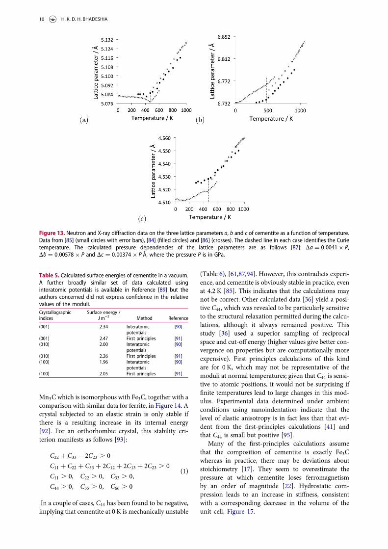
Figure 13 shows diffraction data [84–86] for each ofthe lattice parameters of cementite as a function of temp-erature. The parameter a is most sensitive to the changefrom the ferromagnetic to paramagnetic state, with acontraction evident as the temperature is raised withinthe ferromagnetic range. An increase in the amplitudeof thermal vibrations in an anharmonic interatomicpotential causes expansion, but the spontaneous magne-tisation leads to a contraction, and this latter effect
dominates the a parameter below TC, leading to theobserved Invar type effect, although it is known thatthe analogy with the Invar effect in austenite is tenuous.The orthorhombic structure is preserved through thetransition at TC. It is not clear why the a parameter isparticularly affected by the magnetic transition.
6. Surface energy
The anisotropy of the surface energy of cementite mayhave a role to play in its fracture, particularly at tempera-tures where its plasticity is limited. The energy cost is inthe creation of two new surfaces. Cementite is foundexperimentally to cleave on the {101}, (001), and {102}planes [88]; this is inconsistent with the data presentedin Table 5 where the (001) plane has the highest surfaceenergy when compared with {010} and {100}. It is specu-lated that there is additional work, for example, localisedplasticity, associated with the process, even thoughcementite is brittle at ambient temperature.
7. Elastic properties of single crystals ofcementite
First-principles calculations of the elastic moduli arepresented in Table 6; the anisotropy is illustrated onstereographic plots for cementite and for comparison,
Table 4. Magnetic moments (in units of mB per iron atom) as afunction of a silicon atom substituted into an 8d or 4c iron site.Data from Jang et al. [71]. Similar site-specific data forchromium in cementite are available in Medvedeva et al. [80].
Fe3C (Fe11Si4c)C4 (Fe11Si8d)C4Fe(4c) 2.059 2.021 1.881Fe(8d) 1.957 1.793 1.852
Figure 11. The orthorhombic unit cell with eight metal atoms in the 8d positions (circles), four in the 4c locations and four carbonatoms (small circles). The magnetic structures are from calculations representative of 0 K. (a) Ferromagnetic cementite of compo-sition Fe3C, where all the metal atoms are iron. (b) Mn3C, where all the metal atoms are manganese. The 8d layers are perfectlyantiferromagnetic, whereas the four atoms at 4c locations all have spins aligned; the Mn3C is therefore a ferrimagnet. Adapted fromAppen et al. [81].
Figure 12. The linear thermal expansion coefficient of poly-crystalline cementite as a function of temperature and mag-netic state. Adapted using data from Umemoto et al. [64].
INTERNATIONAL MATERIALS REVIEWS 9
Mn3C which is isomorphous with Fe3C, together with acomparison with similar data for ferrite, in Figure 14. Acrystal subjected to an elastic strain is only stable ifthere is a resulting increase in its internal energy[92]. For an orthorhombic crystal, this stability cri-terion manifests as follows [93]:
C22 + C33 − 2C23 . 0
C11 + C22 + C33 + 2C12 + 2C13 + 2C23 . 0
C11 . 0, C22 . 0, C33 . 0,
C44 . 0, C55 . 0, C66 . 0
(1)
In a couple of cases, C44 has been found to be negative,implying that cementite at 0 K is mechanically unstable
(Table 6), [61,87,94]. However, this contradicts experi-ence, and cementite is obviously stable in practice, evenat 4.2 K [85]. This indicates that the calculations maynot be correct. Other calculated data [36] yield a posi-tive C44, which was revealed to be particularly sensitiveto the structural relaxation permitted during the calcu-lations, although it always remained positive. Thisstudy [36] used a superior sampling of reciprocalspace and cut-off energy (higher values give better con-vergence on properties but are computationally moreexpensive). First principles calculations of this kindare for 0 K, which may not be representative of themoduli at normal temperatures; given that C44 is sensi-tive to atomic positions, it would not be surprising iffinite temperatures lead to large changes in this mod-ulus. Experimental data determined under ambientconditions using nanoindentation indicate that thelevel of elastic anisotropy is in fact less than that evi-dent from the first-principles calculations [41] andthat C44 is small but positive [95].
Many of the first-principles calculations assumethat the composition of cementite is exactly Fe3Cwhereas in practice, there may be deviations aboutstoichiometry [17]. They seem to overestimate thepressure at which cementite loses ferromagnetismby an order of magnitude [22]. Hydrostatic com-pression leads to an increase in stiffness, consistentwith a corresponding decrease in the volume of theunit cell, Figure 15.
Figure 13. Neutron and X-ray diffraction data on the three lattice parameters a, b and c of cementite as a function of temperature.Data from [85] (small circles with error bars), [84] (filled circles) and [86] (crosses). The dashed line in each case identifies the Curietemperature. The calculated pressure dependencies of the lattice parameters are as follows [87]: Da = 0.0041 × P,Db = 0.00578 × P and Dc = 0.00374 × P Å, where the pressure P is in GPa.
Table 5. Calculated surface energies of cementite in a vacuum.A further broadly similar set of data calculated usinginteratomic potentials is available in Reference [89] but theauthors concerned did not express confidence in the relativevalues of the moduli.Crystallographicindices
Surface energy /J m−2 Method Reference
(001) 2.34 Interatomicpotentials
[90]
(001) 2.47 First principles [91](010) 2.00 Interatomic
potentials[90]
(010) 2.26 First principles [91](100) 1.96 Interatomic
potentials[90]
(100) 2.05 First principles [91]
10 H. K. D. H. BHADESHIA
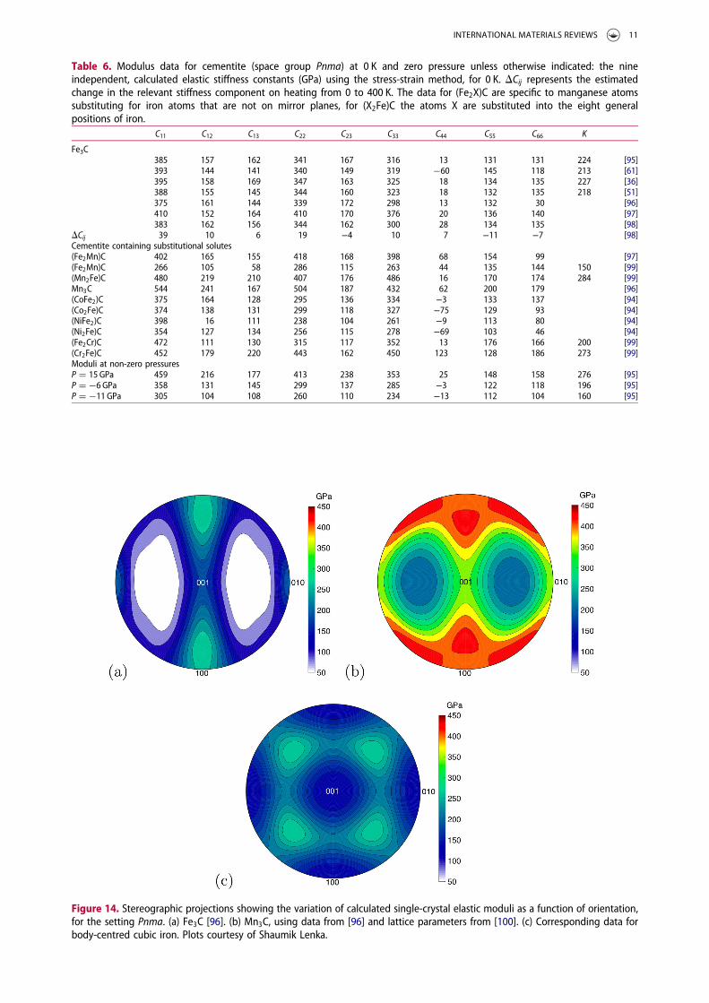
Table 6. Modulus data for cementite (space group Pnma) at 0 K and zero pressure unless otherwise indicated: the nineindependent, calculated elastic stiffness constants (GPa) using the stress-strain method, for 0 K. DCij represents the estimatedchange in the relevant stiffness component on heating from 0 to 400 K. The data for (Fe2X)C are specific to manganese atomssubstituting for iron atoms that are not on mirror planes, for (X2Fe)C the atoms X are substituted into the eight generalpositions of iron.
C11 C12 C13 C22 C23 C33 C44 C55 C66 K
Fe3C385 157 162 341 167 316 13 131 131 224 [95]393 144 141 340 149 319 −60 145 118 213 [61]395 158 169 347 163 325 18 134 135 227 [36]388 155 145 344 160 323 18 132 135 218 [51]375 161 144 339 172 298 13 132 30 [96]410 152 164 410 170 376 20 136 140 [97]383 162 156 344 162 300 28 134 135 [98]
DCij 39 10 6 19 −4 10 7 −11 −7 [98]Cementite containing substitutional solutes(Fe2Mn)C 402 165 155 418 168 398 68 154 99 [97](Fe2Mn)C 266 105 58 286 115 263 44 135 144 150 [99](Mn2Fe)C 480 219 210 407 176 486 16 170 174 284 [99]Mn3C 544 241 167 504 187 432 62 200 179 [96](CoFe2)C 375 164 128 295 136 334 −3 133 137 [94](Co2Fe)C 374 138 131 299 118 327 −75 129 93 [94](NiFe2)C 398 16 111 238 104 261 −9 113 80 [94](Ni2Fe)C 354 127 134 256 115 278 −69 103 46 [94](Fe2Cr)C 472 111 130 315 117 352 13 176 166 200 [99](Cr2Fe)C 452 179 220 443 162 450 123 128 186 273 [99]Moduli at non-zero pressuresP = 15 GPa 459 216 177 413 238 353 25 148 158 276 [95]P = −6 GPa 358 131 145 299 137 285 −3 122 118 196 [95]P = −11 GPa 305 104 108 260 110 234 −13 112 104 160 [95]
Figure 14. Stereographic projections showing the variation of calculated single-crystal elastic moduli as a function of orientation,for the setting Pnma. (a) Fe3C [96]. (b) Mn3C, using data from [96] and lattice parameters from [100]. (c) Corresponding data forbody-centred cubic iron. Plots courtesy of Shaumik Lenka.
INTERNATIONAL MATERIALS REVIEWS 11

In some ingenious experiments, the elastic propertiesof single-crystals of cementite were measured for ambi-ent temperature (Table 7), [102]. The measured moduliare less than those calculated, even though an increase intemperature stiffen the cementite [98]. Koo et al. [102]conducted similar measurements on single crystals ofcementite which may have contained some manganese,estimated to be less than 0.5 wt-%. First principles cal-culations indicate that manganese increases the mod-ulus of cementite (Table 6) consistent with the datathat E100 = 315+ 23 GPa and E001 = 251+ 18 GPa.
8. Elastic properties of polycrystallinecementite
The pressure dependence of the bulk modulus ofcementite is of importance in determining the charac-teristics of the phase at the core of the earth. Measure-ments have therefore been made using diamond anvilcells subjected to synchrotron X-rays to determinethe pressure–volume relationship with the data fittedto an equation of state as follows [103]:
P=!Pr−
12(3Kr−5Pr)
"1−
#VVr
$−2/3%
+ 98Kr
#K ′r−4+ 35Pr
9Kr
$"1−
#VVr
$−2/3%2&#VVr
$−5/3
(2)
Vr is the selected reference volume, and Pr, Kr and K ′r are
the pressure, isothermal bulk modulus and pressure
dependence of that bulk modulus, all at the referencevolume, respectively. The relationship between the bulkmodulus and volume was also given in [103, equation(1b)] but that equation seems to be dimensionally incor-rect. Data corresponding to Equation (2) are as follows:
Magnetic state Kr / GPaV r / Å
3
atom−1Pr /GPa K ′r Reference
Nonmagnetic, 300 K,25 ≥ P ≤ 187 GPa
290±13 9.341 0.0±1.6 3.76± 0.18 [104,105]
The unmodified form of the Birch-Murnaghanequation is [104,106]:
P = 32Ko (V
V0)−7/3 − (V
V0)−5/3
" %
× 1− 34(4− K ′
o) (VV0
)−2/3 − 1" %! &
(3)
where V0 = 155.28 Å3 [104] and Ko are the volumeand isothermal bulk modulus at 1 bar and 300 K,respectively, and K ′
o is the first pressure derivative ofKo at 300 K [104]. With this equation of state, themeasured data are in Table 8.
The data from first-principles calculations of single-crystal elasticity can be used to estimate the elasticproperties of polycrystalline cementite by assuminguniform stress (Reuss) or uniform strain (Voigt)throughout the cementite [109]:
KR=[S11+ S22+ S33+ 2(S12+ S23+ S13)]−1
KV=[C11+ C22+ C33+ 2(C12+ C23+ C13)/9
GR=15
4(S11+ S22+ S33−S12−S23−S13)+ 3(S44+ S55+ S66)
GV=C11+ C22+ C33−C12−C23−C13
15+ C44+ C55+ C66
5
E=9KG/(3K+ G)andn=(3K/[2−G])/(3K+ G)
(4)
where S represents a compliance, E, K and G are theYoung’s, bulk and shear moduli, ν is the Poisson’sratio and the subscripts ‘R’ and ‘V’ representing theReuss andVoigt formulations; the absence of a subscriptindicates an average of the Reuss and Voigt values.Using Jiang et al.’s single-crystal data (Table 6) givesK = 227 GPa, G = 75 GPa, E = 203 GPa and n=0.35 for
Figure 15. Experimentally determined plot of pressure versusdensity for polycrystalline cementite. The gradient increaseswith density, indicating an increase in the bulk modulus withpressure. Data from Fiquet et al. [101].
Table 7. Comparison of the measured and calculated elasticmoduli of pure Fe–C single-crystals of cementite. Data fromKoo et al. [102], rounded off to integers. The uncertaintiesrepresent scatter in experimental data. The calculated valuesare based on first-principles estimates due to Jiang et al. [36].
OrientationMeasured E / GPa (ambient
temperature)Calculated E / GPa
(0 K)
[100] 262+ 32 287[001] 213+ 45 221
Table 8. Measured equation of state data [73]. There are threesets of values stated for the paramagnetic state studies byLitasov et al. [107] corresponding to different equations ofstate used to analyse the experimental data.Magnetic state Ko / GPa K ′0 Reference
Ferromagnetic 179.4+ 7.8 4.8+ 1.6 [73]Ferromagnetic 175.4+ 3.5 5.1+ 0.3 [108]‘Nonmagnetic’ 288+ 42 4 [73]Ferromagnetic 175 5 [107]Paramagnetic 190 4.8 [107]Paramagnetic 191 4.68 [107]Paramagnetic 194 4.6 [107]
12 H. K. D. H. BHADESHIA

zero Kelvin. The Young’s modulus of pure polycrystal-line cementite has beenmeasured to be 196 GPa, but canincrease to values as high as 245 GPa when alloyed withsolutes such as chromium and manganese [64].Measurements on thin (210 nm), polycrystalline filmsof cementite indicate a Young’s modulus of 177 GPa,which gives a shear modulus of 70 GPa assuming thatthe Poisson’s ratio is 0.26 and isotropic elasticity[110,111]. The Poisson’s ratio measured on samples ofcementite containing 28% porosity has been reportedto decrease almost linearly from 0.254 to 0.246 as thetemperature is increased from 95 to 290 K [112].
9. Preparation of cementite
Samples of bulk, pure cementite are difficult to preparegiven that cementite in contact with iron is less stablethan the corresponding equilibrium between graphiteand ferrite. The largest samples have been manufacturedby mechanical alloying in experiments by Umemotoet al. [113]. Powders of iron and graphite in the correctstoichiometric ratio are milled together, resulting in asolid solution, as indicated by very broad ( ≈ 15◦) X-ray diffraction peaks in locations typical of body-centredcubic iron. The mechanically alloyed powder was thenspark plasma sintered under vacuum at 50MPa pressurefor 300 s at 1173 K, inducing the formation of cementite,Figure 16(a) [113]. The density achieved was 7.5 g cm−3,which is less than the measured value for pure cementiteof 7.662 g cm−3 [114] indicating a degree of porosity inthe sintered samples.
The sintering step has been unnecessary in otherwork where cementite was obtained directly duringthe milling process [116–118]. This might be explainedby the fact that Umemoto et al. [113] milled their pow-ders for a much longer time. A comparison of the{110}a X-ray diffraction peaks obtained in the twostudies is shown in Figure 17. The broadening is causedby strain due primarily to dislocations locked withinthe powder, indicating a much larger defect densityin the samples of the Umemoto study. Carbon prefersto be located at dislocations rather than in cementite
[119]; this explains the necessity for the sinteringstage in the Umemoto study.
It has been proposed, based on evidence fromMöss-bauer spectroscopy, that there are intermediate stagesbetween the formation of the solid solution duringmilling, and that of cementite. The process may firstinvolve transition carbides such as Hägg (Fe2C) andɛ-carbide, followed by cementite [120]. Cementitecan be made directly from Hägg carbide through thereaction Fe + Fe2C ( Fe3C [121]. Alternatively, pow-dered cementite can be made by heating Hägg carbide,which is richer in carbon, in a nitrogen stream at 800◦Cfor some 20 min [122]. The resulting sample may con-tain traces of free iron and amorphous carbon. Cemen-tite also forms when a mixture of iron and graphiteheated under a pressure of less than 5 GPa at about1000◦C, Figure 16(b) [115]. Cementite powders havebeen made traditionally by electrochemical extractionfrom steel containing cementite [123].
A clever method [75] for fabricating a ‘single crystal’of cementite is to incorporate electrolytically extractedcementite particles into a resin which then is subjectedto a 10 Tesla magnetic field for some 24 h with thecomposite periodically rotated in the field to magneti-cally align the particles as the resin solidifies. Thisenabled the magnetocrystalline anisotropy of thecementite to be determined experimentally.
Figure 16. (a) A sample of cementite, courtesy of Professor Minoru Umemoto of Toyohashi University. (b) Reaction of 80 wt-% Feand 20 wt-% graphite for 10 min at the temperatures and pressures indicated. Selected data from [115].
Figure 17. A comparison of the {110}u X-ray peaks from theexperiments of Umemoto et al. [113] and Joubouri et al.[118] – the latter has been corrected to the Co Ka wavelengthto permit the comparison.
INTERNATIONAL MATERIALS REVIEWS 13

Iron can be converted into cementite by exposing itto a carburising gas mixture, if the activity of carbonrelative to graphite is maintained at greater than one.Graphite is deposited preferentially unless the surfaceof the iron is contaminated with blocking atoms suchas sulphur, in which case cementite is precipitated[124]. It has been demonstrated that cementite canbe made by carburising magnetite (Fe3O4) at 1073 Kwith carbon monoxide [125]. It is speculated thatcementite produced in this manner could be used inan electrical arc furnace to produce iron while at thesame time reducing carbon dioxide emissions.
Nanoparticles of cementite can be prepared by thethermal decomposition of Fe(CO)5 (iron pentacarbo-nyl). These fine particles may be of use in biomedicinefor delivery of drugs to specific locations within thebody, with the localisation achieved by an externalmagnetic field [126]. Elemental iron particles havebeen proposed for this purpose but they tend to oxidise[127]. Cementite is more corrosion and oxidationresistant,4 while retaining sufficient ferromagnetismto implement the delivery mechanism. Dispersions ofpolymer coated cementite nanoparticles have beenmanufactured by subjecting a gaseous mixture ofC2H4/Fe(CO)5/C5H8O2 to a continuous wave CO2
laser pyrolysis [129], Figure 18.Cementite powder containing pores about 20 nm in
size from an aqueous mixture of iron chloride, colloidalsilica and 4,5-dicyanoimidalzole. The dicyanoimidal-zole is the source of carbon when the mixture is heatedto 700◦C to produce the powder of cementite whichalso contains amorphous silica. The silica is thenremoved by solution in sodium hydroxide, leavingthe porous cementite with a high specific surface areaof 415 m2 g−1. This cementite was demonstrated to becatalytically active in the decomposition of ammoniainto a mixture of hydrogen and nitrogen. Cementiteapparently has greater stability under harsh conditionsthan metallic iron, and is safer with respect to thedanger of explosions associated with fine metallic pow-ders [130]. Cementite has in fact been shown to exhibitcatalytic activity even in the classical Firscher-Torpschprocess for converting gaseous components intohydrocarbon liquids [131].
10. Electrical conductivity
Electrical conductivity data from first-principles calcu-lations, measurements made on cementite-containingmicrostructures and on pure cementite are compiledin Figure 19. The large difference between the calculatedvalue and measurements is attributed to the fact that areal material is likely to contain defects that reduce elec-trical conductivity. The Umemoto data on pure, bulkcementite are from its polycrystalline state [113]; it is
not clear why those due to Lee and Simkovich [132] cor-respond to a much lower conductivity, although it isnoted that the sample preparation methods for thetwo studies are different. The fact that the electricalresistance (i.e. reciprocal of conductivity) increaseswith temperature confirms that cementite is metallicrather than a semiconductor [132].
11. Strength, ductility, toughness and wear
The ideal strength of cementite, i.e. in the absence ofdislocations, can be estimated using first principlesmethods. An increment of strain is applied to a unitcell which then is allowed to relax both in shape andatomic positions, so that only the stress along theapplied direction is non-zero. The stress corresponds
Figure 19. The data on pure cementite are from [113,132], thecalculated datum from [69] and the measurements of mixedmicrostructures, extrapolated to single-phase cementite, from[133].
Figure 18. Cementite nanoparticles produced using laserpyrolysis of a gaseous mixture. Reproduced from Morjanet al. [129] with permission from Elsevier.
4The mechanism of oxidation, i.e. the formation first of Fe3O4 followed by Fe2O3 remains identical to that of metallic iron [128].
14 H. K. D. H. BHADESHIA

to the derivative of the free energy with respect tostrain. The maximum in strength is given by aninstability when an inflexion occurs in the free energyversus strain curve. Calculated data using this methodare illustrated in Figure 20; as expected, there is con-siderable anisotropy in properties.
Early experiments designed to measure the strengthof cementite were confined to small samples extractedfrom high carbon steel. Ribbon-like samples of cemen-tite 1–2 μm thick and 1 mm long when tested by bend-ing gave strength estimates in the range 4.6–8 GPa[134]. Experiments on 2.5μm thick films of cementitewith a grain size of about 50 nm, on samples preparedusing plasma vapour deposition, revealed a microhard-ness of about 1230 HV at ambient temperature,decreasing to about 650 HV at 673 K [110]. Young’smoduli measured on polycrystalline thin films rangefrom 160–180 GPa. More comprehensive hardnessdata are shown in Figure 21; it is clear that hardnessmeasurements from bulk cementite samples preparedby mechanical alloying and spark plasma sintering,are systematically lower than some measurementsmade on eutectic cementite within cast iron, or pre-pared by plasma synthesis. In the latter case the grainsize can be as small as 50 nm which may add somestrengthening, but the intrinsic resistance to plasticdeformation due to the Peierls barrier is likely to be amuch greater contribution. The sintered samples all
contain some porosity which can reduce the strength[135], however, the data from Kagawa and Okamoto[136] from cementite in cast iron, are remarkably con-sistent with those on bulk cementite (Figure 21). Thereis an intriguing study by Drapkin et al. [137] where pri-mary cementite was found to be much harder (≈ 1070–1350 HV) than eutectic cementite (≈ 740–960 HV) incast iron; these data are unexplained.
Indentation fracture toughness values have beenreported for cementite in alloyed cast-iron, i.e.embedded single-crystals of cementite, Table 9 [141].The absolute values of toughness are really quitesmall, but bearing that in mind, vanadium seems toenhance toughness, possibly because it softens thecementite, although the mechanism involved is notknown. The single-crystal mechanical data shouldvary with the crystallographic orientation; the scatterobserved in nanoindentation evaluations of hardnessand modulus [142] may be a consequence of theneglect of orientation effects.
Cementite in steels is often touted as helping resistwear in a variety of applications such as bearings andrails [143–145] where the carbide is present as aminor phase embedded within a matrix of ferrite ormartensite. Figure 22 shows the reciprocal of thewear rate for a variety of samples of ferrite containingdifferent amounts of cementite [146], including datafor pure cementite made by mechanical alloying
Figure 20. Calculated ideal values of ultimate strength at corresponding engineering strains for perfect crystals of cementite. (a)Tensile deformation along crystallographic axes parallel to the cell axes. (b) Shears on the planes and directions indicated. Uniformcolour indicates data from Garvik et al. [51] whereas the cross-hatched bars are from Jiang and Srinivasan [37].
INTERNATIONAL MATERIALS REVIEWS 15

followed by plasma sintering. The reciprocal wear rateis given by PL/V, where P is the applied pressure, and Vis the volume of material lost as the pin of the samplematerial rubs against a rotating alumina disc over a dis-tance L.
As concluded by Sasaki et al. [146], the data showthat at low pressures, the wear rate decreases as theamount of cementite in the sample increases, as longas the abrasion process does not lead to the formationof large brittle chips of cementite. At the high pressure,the brittle chip formation makes the pure cementitewear more rapidly than at low pressures.
12. Substitutional solutes
Alloying cementite with manganese reduces the rate atwhich it might decompose into graphite [147]; it hasbeen known for some time that cementite becomesmore stable when it ‘unites with manganese’, some-times resulting in the growth of robust single-crystalsknown as Speigeleisenkristall [148]. Figure 23(a)shows that the addition of manganese permits cemen-tite to co-exist with graphite and ferrite, whereas in thesame circumstances, a Fe–25C at.-% steel would, atequilibrium, consist only of a mixture of ferrite andgraphite. The cementite in the Fe–C–Mn alloy containsmanganese, the equilibrium composition of which atlow temperatures is more akin to Mn3C than Fe3C(Figure 23(b)).
Chromium hardens cementite, presumably by solidsolution strengthening; Figure 21 shows that the effectis not large. Therefore, the effect of chromiumadditions on the wear resistance of cementite is alsominimal, when the comparison is limited to data forsingle-phase cementite (i.e. neglecting samples withCr, 6 wt-% in [149,150]).
The magnetic properties are affected in line withexpectations, i.e. substituting an atom with a lowermagnetic moment reduces the saturation magnetisa-tion [78,151]. Iron atoms in cementite have local mag-netic moments of 1.97mB or 1.88mB per atom,depending on whether they are located on the mirror
Table 9. Indentation fracture toughness of cementite presentin cast irons at ambient temperature [141]. The hardnessdata measurements include elastic strains and hence will beunderestimated. The chemical compositions representenergy-dispersive X-ray analysis data of the cementite phasealone. The indentation toughness of cementite of unspecifiedcomposition in a nickel-containing cast iron has beenreported to be 4.09+0.68 MPa m1/2 although the reportedhardness of 1340 HV is quite large [140].Alloy content / wt-% Fracture toughness / MPa m1/2 Hardness / HV
9.2 Cr 2.24+0.10 11475.1 Cr 1.52+0.10 10734.5 V 2.74+0.11 936
Figure 21. (a) The Vickers hardness of cementite. The data forpure cementite, filled circles and crosses, are from Umemotoet al. [113] and Kagawa & Okamoto [136]. Umemoto’s dataare from bulk cementite, Kagawa’s from cementite withincast iron. Those for cementite containing chromium at the con-centrations are from Zheng et al. [138]. The curves representmeasurements on cementite in cast iron, alloyed with anunspecified amount of chromium or boron [136]. The hardnessvalues may be underestimates due to some porosity in thesamples. (b) Ambient temperature microhardness data forcementite within a cast iron microstructure [139,140] andfrom plasma deposited Fe3C [110]. The chemical compositionsindicated are in wt-% and represent measurements on cemen-tite alone.
Figure 22. Data from the abrasion of a pin made out of thematerial of interest, against an alumina disc. After Sasakiet al. [146].
16 H. K. D. H. BHADESHIA

or general positions [152]; the corresponding values formanganese and nickel are about 0.8 and 0.6mB,respectively, when substituted into the mirror sites.The addition of nickel therefore reduces the saturationmagnetisation of the alloyed cementite, but the Curietemperature, which depends on the coupling betweenthe magnetic ions, increases [153]. The experimentson nickel-alloying of cementite are limited becausethe cementite tends to be unstable when nickel is forcedinto its lattice by mechanical alloying. During mechan-ical alloying of the stoichiometric mixtures, followed byheat treatment, an amorphous phase forms first, fol-lowed by the crystallisation of nickel-rich cementiteand then the decomposition of the cementite [154].These observations are consistent with first-principlescalculations that show that the substitution of nickel(or cobalt) make the cementite less stable with respectto a mixture of α-iron and graphite [155].
There are circumstances where nickel-containingcementite has a favourable free energy of formation[156]. (Fe,Ni)3C is in fact stable to decomposition at650◦C over a range 10–50 at.-% Ni when the activityof carbon (aC) in the gas with which the carbide is incontact is less than one (Figure 24). It is claimed that(Fe,Ni)3C was detected by metallography and X-raystructure analysis, but it is not clear how these tech-niques reveal the chemical composition of the cemen-tite [156].
Chromium has a strong affinity for carbon andhence when alloyed in cementite, makes the lattermore stable with the free energy of formation decreas-ing systematically with concentration [80,157]. Zhouet al. [158] have published data for chromium incementite showing similar trends although the absolutevalues of formation energy are much greater, even forpure cementite. Manganese too is a carbide former,and once some complex magnetic effects (Section 4)are accounted for, leads to a thermodynamicallymore stable cementite. A compilation of data on a var-iety of solutes affecting the formation energy of cemen-tite at 0 K are presented in Figure 25. There is asignificant variation in DF for pure cementite; the
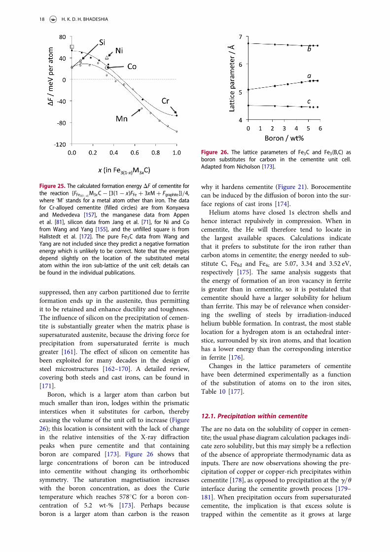
single point by Dick et al. [68] is likely to be themost accurate since the graphite free energy is directlycalculated rather than offset from diamond, although itis noted the van der Waals forces are neglected. Thedata for nickel and cobalt may be uncertain becauseWang and Yan obtained DFFe3C to be negative, in con-tradiction to both experimental and other theory-baseddata, and their paper does not give details of the refer-ence states used. The indications are that scandium,titanium, vanadium, zirconium, and niobium substi-tutions into cementite make it more stable relative toits pure form [159], but their efficacy in this contextmay be compromised by the limits of solubility orthe tendency to form other carbides.
Figure 25 shows that silicon reduces the stability ofcementite, a fact that is of considerable technologicalsignificance. It often is added to steel to suppresscementite while ensuring that the concentration issmall enough that graphite does not form during thefabrication or use of the alloy [160]. If cementite is
Figure 23. Phase diagram calculations for 100 kg total weight, using MTDATA [11] and the SGTE thermodynamic database. Fe–25C–4.08Mn at.-%, permitting cementite, graphite and ferrite to co-exist. (a) Equilibrium phase mixture as a function of tempera-ture. (b) The equilibrium manganese concentration in cementite for the calculations presented in (a).
Figure 24. The free energy of formation associated with the
reaction M + 13C ( M3C occurring at 650◦C, as a function of
the manganese or nickel concentrations. Adapted from Grabkeet al. [156].
INTERNATIONAL MATERIALS REVIEWS 17
suppressed, then any carbon partitioned due to ferriteformation ends up in the austenite, thus permittingit to be retained and enhance ductility and toughness.The influence of silicon on the precipitation of cemen-tite is substantially greater when the matrix phase issupersaturated austenite, because the driving force forprecipitation from supersaturated ferrite is muchgreater [161]. The effect of silicon on cementite hasbeen exploited for many decades in the design ofsteel microstructures [162–170]. A detailed review,covering both steels and cast irons, can be found in[171].
Boron, which is a larger atom than carbon butmuch smaller than iron, lodges within the prismaticinterstices when it substitutes for carbon, therebycausing the volume of the unit cell to increase (Figure26); this location is consistent with the lack of changein the relative intensities of the X-ray diffractionpeaks when pure cementite and that containingboron are compared [173]. Figure 26 shows thatlarge concentrations of boron can be introducedinto cementite without changing its orthorhombicsymmetry. The saturation magnetisation increaseswith the boron concentration, as does the Curietemperature which reaches 578◦C for a boron con-centration of 5.2 wt-% [173]. Perhaps becauseboron is a larger atom than carbon is the reason
why it hardens cementite (Figure 21). Borocementitecan be induced by the diffusion of boron into the sur-face regions of cast irons [174].
Helium atoms have closed 1s electron shells andhence interact repulsively in compression. When incementite, the He will therefore tend to locate inthe largest available spaces. Calculations indicatethat it prefers to substitute for the iron rather thancarbon atoms in cementite; the energy needed to sub-stitute C, Fe8d and Fe4c are 5.07, 3.34 and 3.52 eV,respectively [175]. The same analysis suggests thatthe energy of formation of an iron vacancy in ferriteis greater than in cementite, so it is postulated thatcementite should have a larger solubility for heliumthan ferrite. This may be of relevance when consider-ing the swelling of steels by irradiation-inducedhelium bubble formation. In contrast, the most stablelocation for a hydrogen atom is an octahedral inter-stice, surrounded by six iron atoms, and that locationhas a lower energy than the corresponding intersticein ferrite [176].
Changes in the lattice parameters of cementitehave been determined experimentally as a functionof the substitution of atoms on to the iron sites,Table 10 [177].
12.1. Precipitation within cementite
The are no data on the solubility of copper in cemen-tite; the usual phase diagram calculation packages indi-cate zero solubility, but this may simply be a reflectionof the absence of appropriate thermodynamic data asinputs. There are now observations showing the pre-cipitation of copper or copper-rich precipitates withincementite [178], as opposed to precipitation at the g/uinterface during the cementite growth process [179–181]. When precipitation occurs from supersaturatedcementite, the implication is that excess solute istrapped within the cementite as it grows at large
Figure 25. The calculated formation energy DF of cementite forthe reaction {FFe3(1−x)M3xC− [3(1− x)FFe + 3xM + Fgraphite]}/4,where ‘M’ stands for a metal atom other than iron. The datafor Cr-alloyed cementite (filled circles) are from Konyaevaand Medvedeva [157], the manganese data from Appenet al. [81], silicon data from Jang et al. [71], for Ni and Cofrom Wang and Yang [155], and the unfilled square is fromHallstedt et al. [172]. The pure Fe3C data from Wang andYang are not included since they predict a negative formationenergy which is unlikely to be correct. Note that the energiesdepend slightly on the location of the substituted metalatom within the iron sub-lattice of the unit cell; details canbe found in the individual publications.
Figure 26. The lattice parameters of Fe3C and Fe3(B,C) asboron substitutes for carbon in the cementite unit cell.Adapted from Nicholson [173].
18 H. K. D. H. BHADESHIA

driving forces and low temperatures. This is rather likethe trapping of silicon in cementite that forms at lowtemperatures [71].
13. Thermodynamic properties
There are significant calculations of the heat capacityof cementite, using a combination of density func-tional theory and quantum Monte Carlo methods[68]. These permit the individual contributions ofphonon, electronic and magnetic components, withthe total heat capacity in good agreement with ther-modynamic assessments based on the CALPHADmethod [172]. The calculated values of the differentcomponents are illustrated in Figure 27. Polynomialfunctions describing the free energy of cementite asa function of temperature have been derived by Hall-stedt et al. [172]. CALPHAD type data on cementiteare widely available in the literature so are not repro-duced here, other than in context where they add toinsight or interpretation.
13.1. Stability and graphitisation
It has been known for some time [182–184] thatcementite is metastable with respect to the equilibriumbetween graphite and α-iron for all temperatures belowthe eutectoid in the iron-carbon binary phase diagram.Graphite and γ-iron saturated with graphite form amore stable mixture than cementite and γ-iron forhigher temperatures. On the other hand, if cementite
and α-iron can somehow coexist at temperaturesabove the Fe–C eutectoid, then free energy of for-mation data indicate that the mixture would be stablerelative to α-iron+graphite, Figure 28.
The data presented in Figure 28 are essentially con-sistent with first principles calculations as far as thetemperature dependence of DF is concerned, althoughthe absolute values do not seem to compare well withthermodynamic data [68]. Nevertheless, the cementiteis predicted correctly to be metastable at 0 K, as long asthe ground state energy of graphite is calculated ratherthan an estimation based on a shift from that of dia-mond [68]. There exists a contradictory first-principlescalculation [155] that suggests DF , 0 at 0 K, but thereare insufficient details presented about how the groundstate energy of graphite has been introduced.
Cementite presumably is easier to nucleate in thesolid-state than graphite, hence its ubiquitous in itsmetastable form. One consequence is the phenomenonof metal dusting, associated with the formation ofcementite due to the desorption of gases such as COon the steel surface at an elevated temperature (400–800◦C) when the activity of carbon in the gas issufficiently large [156]. The oxygen partial pressureshould be low enough to ensure that oxide formationdoes not become the dominant degradation mechan-ism. The cementite then decomposes into fine particlesof iron and graphite, i.e. the dust. An addition of asmall amount of hydrogen sulphide to the carburisinggas leads to the adsorption of a monolayer of sulphurwhich helps retard its decomposition into graphiteand iron [185].
Figure 27. The calculated components of the heat capacity ofcementite as a function of temperature at zero pressure;adapted from Dick et al. [68].
Table 10. Change in the lattice parameters of cementite (Pnma) as a function of the concentration in wt-%. The coefficients arederived from the work of Kagawa and Okamoto [177].Solute Da / Å wt-%−1 Db / Å wt-%−1 Dc / Å wt-%−1 Concentration limit / wt-%
Mo 0.001276732 0.007352941 0.002538071 3.2Mn −0.002061431 0 −0.001239669 4.85Cr −0.002328289 −0.001445087 −0.000874126 3.49Ni −0.001637331 −0.000814332 −0.000404858 2.08
Figure 28. The formation energy DF of cementite for the reac-tion FFe3C − [3FFe + Fgraphite]/4. Data from CALPHAD assess-ment by Hallstedt et al. [172]. A negative value implies thatcementite becomes stable relative to the mixture of α andgraphite.
INTERNATIONAL MATERIALS REVIEWS 19

The formation of graphite leads to a large expansionin volume:
Fe3C'()*(+Vu
( 3Fe')*+0.911Vu
+ graphite'((()*(((+0.227Vu
= 1.138Vu
where Vu is the volume of cementite. Therefore, unlessvoids are associated with cementite, it would be necess-ary for iron to diffuse in order to accommodate thegrowing graphite [186]. Phosphorus and sulphurretard the process of graphitisation by segregation toany void surfaces, or possibly to ferrite-cementiteinterfaces.
Samples of cementite have been prepared by thereaction of Fe2O3 with a mixture of 10% CO2–H2
[187] for the purposes of thermal stability assessments.The samples had an average carbon concentration ofless than the stoichiometric proportion, so probablycontained some iron. They tended to decompose intomixtures of carbon and iron when heated in pureargon at temperatures in the range 800–1100 K forperiods of 10–60 min. As noted previously (Section1), cementite that is in contact with iron decomposesmore rapidly than when the cementite is isolatedwithin a surrounding of carbon [6,7]. The decompo-sition of carbon-rich gases can be catalysed on ironparticles, leading first to the conversion of the iron par-ticles into cementite, which then decomposes into amixture of carbon nanotubes and iron particleswhich may become embedded within the tubes [188].
Cementite can be synthesised by gas(CH4 + H2 + Ar) carburising iron-oxides at about750◦C. Figure 29 shows the thermal stability of suchcementite in the form of time–temperature–transform-ation curves, when the carbide is reheated to a varietyof temperatures. The rate at which the cementitedecomposes is a lot slower when it is made from titano-magnetite; this was attributed to titanium dissolved inthe cementite which makes it more stable to decompo-sition when compared against the binary cementitegenerated from haematite [189]. A difficulty with this
interpretation is that phase diagram calculationsusing the CALPHAD method indicate that there isno solubility of titanium in cementite [190]; the tita-nium is more likely to be dissolved in the residualiron reported by Longbottom et al. [189]. However,the same calculations show that when pure cementiteis in equilibrium with iron-containing dissolved tita-nium, the cementite becomes stable to the formationof graphite.
Some calculations indicate that the orthorhombic η–Fe2C, monoclinic χ–Fe5C2 and cubic Fe23C6 are allthermodynamically more stable than cementite atzero Kelvin [191]. A temperature dependence calcu-lated for cementite to include lattice vibrations andmagnetic contributions for the cementite and η indi-cated that the former becomes more stable when pre-cipitation occurs below 330 K. Similar estimates werenot made for Fe23C6 and χ-carbide. In practice, kineticfactors such as the activation energy for nucleation,which is a sensitive function of interfacial energy, willplay a role in the sequence of precipitation. Othersolutes commonly present in steel may alter these con-siderations. After all, transition carbides of iron oftenprecede cementite during the temperature of marten-site or the formation of bainite at temperatures wellabove 330 K.
14. Cementite precipitation in metallic glass
Amorphous alloys of iron precipitate cementite whentheir carbon concentration is sufficiently large; it isdifficult to be specific because there is no phase dia-gram relating to the equilibrium between cementiteand the glassy alloy or even whether an equilibriummixture of glass and cementite is possible. Figure 30shows cementite and ferrite obtained by the devitrifica-tion of a binary glassy-steel 500 nm thick film duringheat treatment at just 300◦C. It is not clear why thecementite is heavily faulted but its shape indicates
Figure 29. Time, temperature and 50% transformation dia-grams for the decomposition of cementite into elementaliron and carbon. In one case, the cementite is made by carbur-ising haematite ore (Fe2O3), and in the other by similarly car-burising titanomagnetite (Fe(1−x)TixO4). Selected data fromLongbottom et al. [189].
Figure 30. Cementite (majority phase, containing planar faults)and equiaxed ferrite, crystallised from metallic glass films ofcomposition Fe–13.6C at.-% by heat treatment at 300◦C for3 h. Reproduced from Fillon et al. [192] with permission fromElsevier.
20 H. K. D. H. BHADESHIA

that the growth process is reconstructive in nature.This would require the diffusion of iron atoms, andindeed, the rate of transformation is found to be slowerthan expected from the diffusion of carbon alone [192].
Metallic glasses have a larger free volume thansupercooled liquid because they essentially becomeconfigurationally frozen once below the glass-tran-sition temperature. It is expected therefore that diffu-sion coefficients will be greater than in the crystallineversion of the material. The measurement of diffusioncoefficients is complicated by the fact that the glass willundergo structural changes such as relaxation and ulti-mately, devitrification, when measurements are con-ducted. Experiments on the diffusion of iron in avariety of metallic glasses in their relaxed condition,show that there is indeed an enhanced diffusivity inthe glassy state (Figure 31, [193]).
15. Carbon nanotubes – role of cementite
Carbon nanotube formation from gaseous hydrocar-bons is catalysed by fine particles of transition metals,particularly iron. Bulky iron or thin films of iron arenot as effective as dispersed fine particles [196]; thisis because flat surfaces do not form good templatesfor the growth of tubes, and indeed, the size of catalystparticles correlates with the diameters of the nanotubesgenerated [e.g. [197]].
Iron does catalyse the breakdown of hydrocarbonsin appropriate circumstances, but there has been dis-cussion [reviewed in Section 5.1.3, [198]] aboutwhether it is the iron particles or the cementiteparticles that form subsequently, that induce thenucleation and growth of multiwalled or single-walledcarbon nanotubes. Environmental transmission elec-tron microscopy has provided clear evidence for ‘gra-phitic networks’ first forming on cementite particles,followed by the genesis of carbon nanotube growth
[199,200]. The process of carbon depositing on thecementite particle is not uniform, so carbon diffusesthrough the cementite from the graphite-rich regionto that which is not coated, leading to the expulsionof carbon filaments [196].
Not everyone accepts these conclusions about therole of cementite; Tessonnier et al. [201] comment onelectron beam-induced artefacts and the possible roleof surface diffusion. Nevertheless, X-ray diffractionexperiments involving nanotube formation in afluidised bed where a mixture of ethylene, hydrogenand nitrogen is catalysed to decompose by iron sup-ported on alumina, indicate that the iron is convertedinto metastable cementite which then decomposesinto a more stable mixture of iron and carbon-nano-tubes, rather like the ordinary process of graphitisation[188]. Mössbauer spectroscopy and transmission elec-tronmicroscopy of nanotubes synthesised by the cataly-tic decomposition of acetylene on iron particles haveshown that while α-iron is the active centre for thebreakdown of acetylene, cementite formation inducesthe growth of the carbon nanotubes [202].
The presence of α-iron or cementite particles withincarbon nanotubes can add a magnetic function that hasthe potential for exploitation in devices. Tubes syn-thesised the pyrolysis of liquid hydrocarbon in a mix-ture containing ferrocene [Fe(C2H5)2] end up withsome 90% of the particles within being cementite, act-ing as single-domain ferromagnets [203].
16. Conclusions
The need to understand cementite comes from its met-allurgical importance, it can help interpret data on theEarth’s inner core and in order to understand why itoccurs in meteorites which will have cooled incrediblyslowly. Raw particles of ferromagnetic cementite mayin the future play a role in the delivery of drugs tospecific locations within the body. And it is clear thatcementite, like body-centred cubic iron, has catalyticproperties, but is more resistant to oxidation than theiron. Cementite can now be manufactured in sizeablesamples, and there are a number of mechanisms bywhich nanoparticles of cementite can be made. As aresult, its intrinsic properties have been characterisedin detail over a very large range of temperatures andpressures. The phase has been a fertile ground forfirst-principles calculations of the effect of alloyingelements substituting for iron or carbon, and on itsmagnetic structure. There are a few puzzling obser-vations that have been published but do not seem tohave been followed-up:
. There are large discrepancies in hardness datawhich do not seem to be at fault or attributable towhether they represent micro- or macro-hardnessmeasurements.
Figure 31. 59Fe tracer diffusion coefficients in Fe–Zr and Fe–Bglassy metals in the relaxed state. Self-diffusion data for iron inferrite are included from [194,195], for comparison purposes.Selected data on the amorphous alloys from Horvath et al.[193].
INTERNATIONAL MATERIALS REVIEWS 21
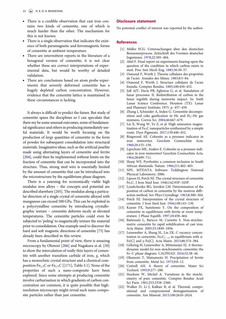
. There is a credible observation that cast iron con-tains two kinds of cementite, one of which ismuch harder than the other. The mechanism forthis is not known.
. There is a single observation that indicates the exist-ence of both paramagnetic and ferromagnetic formsof cementite at ambient temperature.
. There are intermittent reports in the literature of ahexagonal version of cementite; it is not clearwhether these are correct interpretations of exper-imental data, but would be worthy of detailedvalidation.
. There are conclusions based on atom probe exper-iments that severely deformed cementite has ahugely depleted carbon concentration. However,evidence that the cementite lattice is maintained inthese circumstances is lacking.
It always is difficult to predict the future. But study ofcementite spans the disciplines so I can speculate thattheremy be some unusual outcomes, some of fundamen-tal significance and others in producing immediately use-ful materials. It would be worth focusing on theproduction of large quantities of cementite in the formof powder for subsequent consolidation into structuralmaterials. Imaginative ideas, such as the artificial pearlitemade using alternating layers of cementite and ferrite[204], could then be implemented without limits on thefraction of cementite that can be incorporated into thestructure. Thus, strong steel wire is essentially limitedby the amount of cementite that can be introduced intothe microstructure by the equilibrium phase diagram.
There is a yearning for economically viable highmodulus iron alloys – the concepts and potential aredescribed elsewhere [205]. The modulus along a particu-lar direction of a single crystal of cementite alloyed withmanganese can exceed 500 GPa. This can be exploited ina polycrystalline cementite by introducing crystallo-graphic texture – cementite deforms nicely at elevatedtemperatures. The cementite particles could even besubjected to ‘poling’ to magnetically texture the materialprior to consolidation. One example used to discover thehard and soft magnetic directions of cementite [75] hasalready been described in this review.
From a fundamental point of view, there is amazingmicroscopy by Ohmori [206] and Nagakura et al. [50]to show the intercalation of really thin layers of cemen-tite with another transition carbide of iron, χ, whichhas a monoclinic crystal structure and a chemical com-position Fe2.2C or Fe2.5C [[171], Table 3.1]. None of theproperties of such a nano-composite have beenexplored. Since some attempts at producing cementiteinvolve carburisation in which gradients of carbon con-centration are common, it is quite possible that high-resolution microscopy might reveal such nano-compo-site particles rather than just cementite.
Disclosure statement
No potential conflict of interest was reported by the author.
References
[1] Müller FCG. Untersuchungen über den deutschenBesssemerprocess. Zeitschrift des Vereines deutscherIngenieure. 1978;22:385–404.
[2] Abel F. Final report on experiments bearing upon thequestion of the condition in which carbon exists insteel. Proc Inst Mech Eng. 1885;36:30–57.
[3] Osmond F, Werth J. Theorie cellulaire des propriétésde l’acier. Annales des Mines. 1885;8:5–84.
[4] Osmond F, Werth J. Structure cellulaire de l’acierfoundu. Comptes Rendus. 1885;100:450–452.
[5] Jull AJT, Davis PR, Eglinton G, et al. Simulation oflunar processes: II. Redistribution of carbon in thelunar regolith during meteorite impact. In: SixthLunar Science Conference. Houston (TX): Lunarand Planetary Institute; 1975. p. 457–459.
[6] Zhang J, Schneider A, Inden G. Cementite decompo-sition and coke gasification in He and H2–He gasmixtures. Corros Sci. 2004;46:667–679.
[7] Lei X, Wang W, Ye Z, et al. High saturation magne-tization of Fe3C nanoparticles synthesized by a simpleroute. Dyes Pigments. 2017;139:448–452.
[8] Ringwood AE. Cohenite as a pressure indicator iniron meteorites. Geochim Cosmochim Acta.1960;20:155–158.
[9] Lipschutz ME, Anders E. Cohenite as a pressure indi-cator in iron meteorites? Geochim Cosmochim Acta.1964;28:699–711.
[10] Sharp WE. Pyrrhotite: a common inclusion in SouthAfrican diamonds. Nature. 1966;211:402–403.
[11] NPL. MTDATA. Software. Teddington: NationalPhysical Laboratory; 2006.
[12] Lipson H, Petch NJ. The crystal structure of cementiteFe3C. J Iron Steel Inst. 1940;142:95P–103P.
[13] Lyashchenko BG, Sorokin LM. Determination of theposition of carbon in cementite by the neutron diffr-action method. Sov Phys Crystallogr. 1963;8:300–304.
[14] Petch NJ. Interpretation of the crystal structure ofcementite. J Iron Steel Inst. 1944;149:143–150.
[15] Kayser FX, Sumitomo Y. On the composition ofcementite in equilibrium with ferrite at room temp-erature. J Phase Equilib. 1997;18:458–464.
[16] Battezzati L, Baricco M, Curiotto S. Non-stoichio-metric cementite by rapid solidification of cast iron.Acta Mater. 2005;53:1849–1856.
[17] Leineweber A, Shang SL, Liu ZK. C-vacancy concen-tration in cementite, Fe3C1−z , in equilibrium with α-Fe[C] and γ-Fe[C]. Acta Mater. 2015;86:374–384.
[18] Göhring H, Leineweber A, Mittemeijer EJ. A thermo-dynamic model for non-stoichiometric cementite; theFe–C phase diagram. CALPHAD. 2016;52:38–46.
[19] Okamoto T, Matsumoto H. Precipitation of ferritefrom cementite. Metal Sci. 1975;9:8–12.
[20] Cottrell AH. A theory of cementite. Mater SciTechnol. 1993;9:277–280.
[21] Stuckens W, Michel A. Variations in the stoichi-ometry of pure cementite. Comptes Rendus AcadSci Paris. 1961;253:2358–2360.
[22] Walker D, Li J, Kalkan B, et al. Thermal, compo-sitional and compressional demagnetization ofcementite. Am Mineral. 2015;100:2610–2624.
22 H. K. D. H. BHADESHIA
[23] Choe HJ, Terai T, Fukuda T, et al. Easy axis of mag-netization of Fe3C prepared by an electrolytic extrac-tion method. J Magn Magn Mater. 2016;417:1–5.
[24] Duman E, Acet M, Wassermann EF. Magneticinstabilities in Fe3C cementite particles observedwith Fe K-Edge X-ray circular dichroism underpressure. Phys Rev Lett. 2005;94:075502.
[25] Khmelevskyi S, Ruban AV, Mohn P. Electronic struc-ture analysis of the pressure induced metamagnetictransition and magnetovolume anomaly in Fe3C –cementite. J Phys Condens Matter. 2005;17:7345–7352.
[26] Kitaguchi HS, Lozano-Perez S, Moody MP.Quantitative analysis of carbon in cementite usingpulsed laser atom probe. Ultramicroscopy.2014;147:51–60.
[27] Hong MH, Reynolds WT Jr., Tarui T, et al. Atomprobe and transmission electron microscopy investi-gations of heavily drawn pearlitic steel wire. MetallMater Trans A. 1999;30:717–727.
[28] Voronin VI, Berger IF, Gornostyrev YuN, et al.Composition of cementite in the dependence on thetemperature. In situ neutron diffraction study andab initio calculations. JETP Lett (English version).2010;91:143–146.
[29] Zhukov AA, Shalashov VA, Tomas VK, et al.Variation of the composition, structure, and hardnessof cementite with quenching. Metal Sci Heat Treat.1970;12:16–18.
[30] Zhukov AA, Polovinchuk VP, Osadchuk AYu, et al.Transformations in cementite in the zone of contactwith ferrous phases. Metals Sci Heat Treat.1992;34:723–725.
[31] Fasiska EJ, Jeffrey GA. On the cementite structure.Acta Crystallogr. 1965;19:463–471.
[32] Maratkanova AN, Surnin DV, Deev AN, et al. EEFLSstudy of the cementite local structure. J SynchrotronRad. 2001;8:413–415.
[33] Elsukov EP, Dorofeev GA, Ul’yanov AL, et al. On theproblem of the cementite structure. Phys MetalsMetall. 2006;102:76–82.
[34] Jiang C, Maloy SA, Srinivasan SG. A computationalmethod to identify interstitial sites in complexmaterials. Scripta Mater. 2008;58:739–742.
[35] Kawakami K, Matsumiya T. Ab-initio investigation ofhydrogen trap state by cementite in bcc-Fe. ISIJ Int.2013;53:709–713.
[36] Jiang C, Srinivasan SG, Caro A, et al. Structural, elas-tic, and electronic properties of Fe3C from first prin-ciples. J Appl Phys. 2008;103:043502.
[37] Jiang C, Shrinivasan SG. Unexpected strain-stiffeningin crystalline solids. Nature. 2013;496:339–342.
[38] Leineweber A. Anisotropic microstrain broadening incementite, Fe3C, caused by thermal microstress: com-parison between prediction and results from diffrac-tion-line profile analysis. J Appl Crystallogr.2012;45:944–949.
[39] Leineweber A. Thermal expansion anisotropy assource for microstrain broadening of polycrystallinecementite, Fe3C. J Appl Crystallogr. 2016;49:1632–1644.
[40] Inoue A, Ogura T, Muramatsu T. Burgers vectors ofdislocations in cementite crystal. Scripta Metall.1977;11:1–5.
[41] Alkorta J, Sevillano JG. Assessment of elastic aniso-tropy and incipient plasticity in Fe3C by nanoinden-tation. J Mater Res. 2012;27:45–52.
[42] Mizuno M, Tanaka I, Adachi H. Effect of solute atomson the chemical bonding of Fe3C (cementite). PhilosMag B. 1997;75:237–248.
[43] Inoue A, Ogura M, Masumoto K. Lattice defects anddeformation / fracture behavior of cementite in steel.Bull Jpn Inst Metals. 1974;13:653–664.
[44] Gil-Sevillano J. Room temperature plastic defor-mation of pearlitic cementite. Mater Sci Eng.1975;21:221–225.
[45] Karkina LE, Karkin IN, Kabanova IG, et al.Crystallographic analysis of slip transfer mechanismsacross the ferrite/cementite interface in carbon steelswith fine lamellar structure. J Appl Crystallogr.2015;48:97–106.
[46] Mussi A, Cordier P, Ghosh S, et al. Transmission elec-tron microscopy of dislocations in cementitedeformed at high pressure and high temperature.Philos Mag. 2016;96:1773–1789.
[47] Ghaffarian H, Taheri AK, Kang K, et al. Moleculardynamics simulation study of the effect of temperatureand grain size on the deformation behavior of poly-crystalline cementite. Scripta Mater. 2015;95:23–26.
[48] Nishiyama A, Kore’eda A, Katagiri S. Study of planedefects in the cementite by transmission electronmicroscopy. Trans JIM. 1964;5:115–121.
[49] Kar’kina LE, Kar’kin IN, Zubkova TA. Atomisticsimulation of stacking faults in cementite: planes con-taining vector [100]. Phys Metals Metallogr.2014;115:814–829.
[50] Nakamura Y, Mikami T, Nagakura S. In situ hightemperature electron microscopic study of the for-mation and growth of cementite particles in thethird stage of tempering. Trans Jpn Inst Metals.1985;26:876–885.
[51] Garvik N, Carrez Ph, Cordier P. First-principles studyof the ideal strength of Fe3C cementite. Mater Sci EngA. 2013;572:25–29.
[52] Nematollahi GhA, von Pezold J, Neugebauer J, et al.Thermodynamics of carbon solubility in ferrite andvacancy formation in cementite in strained pearlite.Acta Mater. 2013;61:1773–1784.
[53] Jiang C, Uberuaga BP, Srinivasan SG. Point defectthermodynamics and diffusion in Fe3C: a first prin-ciples study. Acta Mater. 2008;56:3236–3244.
[54] Henriksson KOE. Cascades in model steels: the effectof cementite (Fe3C) and Cr23C6 particles on short-term crystal damage. Nucl Instrum Methods PhysRes B. 2015;352:36–38.
[55] Henriksson KOE, Nordlund K. Irradiation cascadesin cementite: 0.1–10 keV Fe recoils. Nucl InstrumMethods Phys Res B. 2012;277:136–139.
[56] Henriksson KO, Nordlund K. Mechanical and elasticchanges in cementite Fe3C subjected to cumulative 1keV Fe recoils. Nucl Instrum Methods Phys Res B.2014;338:119–125.
[57] Nagakura S. Study of metallic carbides by electrondiffraction part III. Iron carbides. J Phys Soc Japan.1959;14:186–195.
[58] Jack KH. Results of further X-ray structural investi-gations of the iron-carbon and iron-nitrogen systemsand of related interstitial alloys. Acta Crystallogr.1950;3:392–394.
[59] Jack DH, Jack KH. Carbides and nitrides in steel.Mater Sci Eng. 1973;11:1–27.
[60] Liu Z, Li Z, Liu W. Calculation of the valence electronstructures of alloying cementite and its biphase inter-face. Sci China Ser E. 2001;44:542–552.
INTERNATIONAL MATERIALS REVIEWS 23
[61] Lv ZQ, Zhang FC, Sun SH, et al. First-principles studyon the mechanical, electronic and magnetic proper-ties of Fe3C. Comput Mater Sci. 2008;44:690–694.
[62] Christoffersen R, Buseck PR. Epsilon carbide: a lowtemperature component of interplanetary dust par-ticles. Science. 1983;222:1327–1329.
[63] Trepcznśka Łent M. Directional solidification of Fe–Fe3C white eutectic alloy. Crystal Res Technol.2017;52:1600359.
[64] Umemoto M, liu ZG, Masuyama K, et al. Influence ofalloy additions on production and properties of bulkcementite. Scripta Mater. 2001;45:391–397.
[65] Wologdine M. Note sur les propriétés magnétiques dequelques composés du fer. Comptes Rendus.1909;148:776–777.
[66] Smith SWJ, White W, Barker SG. The magnetic tran-sition temperature of cementite. Proc Phys SocLondon. 1911;24:62–69.
[67] HondaK, TakagiH.On themagnetic transformation ofcementite. Sci Rep Tohoku Imp Univ. 1915;4:161–167.
[68] Dick A, Körmann F, Hickel T, et al. Ab initio baseddetermination of thermodynamic properties ofcementite including vibronic, magnetic, and elec-tronic excitations. Phys Rev B. 2011;84:125101.
[69] Häglund J, Grimvall G, Jarlberg T. Electronic struc-ture, X-ray photoemission spectra, and transportproperties of Fe3C (cementite). Phys Rev B.1991;44:2914–2919.
[70] Arzhnikov AK, Dobysheva LV, Demangeat C.Structural peculiarities of cementite and their influ-ence on magnetic characteristics. J Phys CondensMatter. 2007;19:196214.
[71] Jang JH, Kim IG, Bhadeshia HKDH. Substitutionalsolution of silicon in cementite: a first-principlesstudy. Comput Mater Sci. 2009;44:1319–1326.
[72] Jang JH. Private communication to H. K. D. H.Bhadeshia. First principles calculations. 2018 Jul.
[73] Lin JF, Struzhkin VV, Mao HK, et al. Magentic tran-sition in compressed Fe3C from X-ray emission spec-troscopy. Phys Rev B. 2004;70:212405.
[74] Reznik B, Kontny A, Uehara M, et al. Magneticdomains and magnetic stability of cohenite from theMorasko iron meteorite. J Magn Magn Mater.2017;426:594–603.
[75] Yamamoto S, Terai T, Fukuda T, et al.Magnetocrystalline anisotropy of cementite pseudosingle crystal fabricated under a rotating magneticfield. J Magn Magn Mater. 2018;451:1–4.
[76] Keh AS, Johnson CA. Ferromagnetic domain struc-tures in cementite. J Appl Phys. 1963;34:2670–2676.
[77] Hillert M. The kinetics of the first stage of tempering.Acta Metall. 1959;7:653–658.
[78] Dobysheva LV. First-principles calculations foralloyed cementite (Fe–Ni)3C. Bull Russ Acad Sci.2017;81:798–802.
[79] Ul’yanov AI, Chulkina AA, Volkov VA, et al.Structural state and magnetic properties of cementitealloyed with manganese. Phys Metals Metallogr.2012;113:1134–1145.
[80] Medvedeva NI, Shein IR, Konyaeva MA, et al. Effectof chromium on the electronic structure and mag-netic properties of cementite. Phys MetalsMetallogr. 2008;105:568–573.
[81] von Appen J, Eck B, Dronskowski R. A density-func-tional stude of the phase diagram of cementite-type(Fe,Mn)3C at absolute zero temperature. J ComputChem. 2010;31:2620–2627.
[82] Kaeswurm B, Friemert K, G’ursoy M, et al. Directmeasurement of the magnetocaloric effect in cemen-tite. J Magn Magn Mater. 2016;410:105–108.
[83] Ron M, Shechter H, Hirsch AA, et al. On theMössbauer study of cementite. Phys Lett.1966;20:481–483.
[84] Reed RC, Root JH. Determination of the temperaturedependence of the lattice parameters of cementite byneutron diffraction. Scripta Mater. 1997;38:95–99.
[85] Wood IG, Vočadlo L, Knight KS, et al. Thermalexpansion and crystal structure of cementite, Fe3C,between 4 and 600 K determined by time-of-flight neu-tron powder diffraction. J Appl Crystallogr.2004;37:82–90.
[86] Litasov KD, Rashchenko SV, Shmakov AN, et al.Thermal expansion of iron carbides, Fe7C3 andFe3C, at 297–911 K determined by in situ X-ray diffr-action. J Alloys Comp. 2015;628:102–106.
[87] Gorai S, Ghosh PS, Bhattacharya C, et al. Ab-initiostudy of pressure evolution of structural, mechanicaland magnetic properties of cementite (Fe3C) phase.In: AIP Conference Proceedings. vol. 1942.New York (NY): AIP Publishing; 2018. p. 030015.
[88] Inoue A, Ogura T, Masumoto T. Deformation andfracture behaviours of cementite. Trans JIM.1976;17:663–672.
[89] Liyange LSI, Kim SG, Houze J, et al. Structural, elastic,and thermal properties of cementite (Fe3C) calculatedusing a modified embedded atom method. Phys RevB. 2014;2014:094102.
[90] Ruda M, Farkas D, Garcia G. Atomistic simulations inthe Fe–C system. ComputMater Sci. 2009;45:550–560.
[91] Chiou WC Jr., Carter EA. Structure and stability ofFe3C cementite surfaces from first principles. SurfSci. 2003;530:88–100.
[92] Born M. On the stability of crystal lattices. I. MathProc Cambridge Philos Soc. 1940;36:160–172.
[93] Patil SKR, Khare SV, Tuttle BR, et al. Mechanicalstability of possible structures of PtN investigatedusing first-principles calculations. Phys Rev B.2006;73:104118.
[94] Wang CX, Lv ZQ, Fu WT, et al. Electronic properties,magnetic properties and phase stability of alloyedcementite (Fe,M)3C (M=Co,Ni) from density-func-tional theory calculations. Solid State Sci.2011;13:1658–1663.
[95] Nikolussi M, Shang SL, Gressmann T, et al. Extremeelastic anisotropy of cementite, Fe3C: First-principlescalculations and experimental evidence. ScriptaMater. 2008;59:814–817.
[96] Ghosh G. A first-principles study of cementite (Fe3C)and its alloyed counterparts: elastic constants, elasticanisotropies, and isotropic elastic moduli. AIP Adv.2015;5:087102.
[97] Huang L, Tu Y, Wang X, et al. Site preference ofmanganese in mn-alloyed cementite. Phys StatusSolidi B. 2016;253:1623–1628.
[98] Mauger L, Herriman JE, Hellman O, et al. Phononsand elasticity of cementite through the Curie temp-erature. Phys Rev B. 2017;95:024308.
[99] Lv ZQ, Fu WT, Sun SH, et al. First-principles studyon the electronic structure, magnetic properties andphase stability of alloyed cementite with Cr or Mn. JMagn Magn Mater. 2011;323:915–919.
[100] Dierkes H, Dronskowski R. High-resolution powderneutron diffraction on Mn3C. Zeitschrift für anorga-nische und allgemeine Chemie. 2014;640:3148–3152.
24 H. K. D. H. BHADESHIA

[101] Fiquet G, Badro J, Gregoryanz E, et al. Sound velocityin iron carbide (Fe3C) at high pressure: implicationsfor the carbon content of the earth’s inner core.Phys Earth Planet Inter. 2009;172:125–129.
[102] Koo BW, Chang YJ, Hong SP, et al. Experimentalmeasurement of Young’s modulus from a single crys-talline cementite. Scripta Mater. 2014;82:25–28.
[103] Sata N, Shen G, Rivers ML, et al. Pressure-volumeequation of state of teh high-pressure B2 phase ofNaCl. Phys Rev B. 2002;65:104114.
[104] Li J, Mao HK, Fei Y, et al. Compression of Fe3C to 30GPa at room temperature. Phys Chem Miner.2002;29:166–169.
[105] Sata N, Hirose K, Shen G, et al. Compression of FeSi,Fe3C, Fe0.95O, and FeS under core pressures andimplication for light element in the earth’s core. JGeophys Res. 2010;115:B09204.
[106] Birch F. Equation of state and thermodynamic par-ameters of NaCl to 300 kbar in the high-temperaturedomain. J Geophys Res. 1986;91:4949–4954.
[107] Litasov KD, Sharygin IS, Dorogokupets PI, et al.Thermal equation of state and thermodynamic prop-erties of iron carbide Fe3C to 31 GPa and 1473 K. JGeophys Res. 2013;118:1–11.
[108] Scott HP, Williams Q, Knittle. E. Stability andequation of state of cementite to 73 GPa: implicationsfor carbon in the earth’s core. Geophys Res Lett.2001;28:1875–1878.
[109] Panda KB, Ravi Chandran KS. First principlesdetermination of elastic constants and chemicalbonding of titanium boride (TiB) on the basis of den-sity functional theory. Acta Mater. 2006;54:1641–1657.
[110] Li SJ, Ishihara M, Yumoto H, et al. Characterisation ofcementite films prepared by electron-shower-assistedPVD method. Thin Solid Films. 1998;316:100–104.
[111] Mizubayashi H, Li SJ, Yumoto H, et al. Young’s mod-ulus of single phase cementite. Scripta Mater.1999;40:773–777.
[112] Dodd SP, Saunders GA, Cankurtaran M, et al.Ultrasonic study of the temperature and hydrostaticpressure dependences of the elastic properties of poly-crystalline cementite (Fe3C). Phys Status Solidi A.2003;198:272–281.
[113] Umemoto M, Liu ZG, Takaoka H, et al. Production ofbulk cementite and its characterization. Metall MaterTrans A. 2001;32:2127–2131.
[114] Ishigaki T. Determination of the density of cementite.Sci Rep Tohoku Imp Univ. 1927;16:295–302.
[115] Tsuzuki A, Sago S, Hirano S, et al. High temperatureand pressure preparation and properties of ironcarbides Fe7C3 and Fe3C. J Mater Sci. 1984;19:2513–2518.
[116] Chaira D, Mishra BK, Sangal S. Magnetic propertiesof cementite powder produced by reaction milling. JAlloys Comp. 2009;474:396–400.
[117] Al-Joubori AA, Suryanarayana C. Synthesis of Fe–Calloys by mechanical alloying. In: Materials Science& Technology Conference and Exhibition 2014.Vol. 1. New York (NY): Curran Associates Inc;2014. p. 509–516.
[118] Al-Joubori AA, Suryanarayana C. Synthesis and ther-mal stability of homogeneous nanostructured Fe3C(cementite). J Mater Sci. 2018;53:7877–7890.
[119] Kalish D, Cohen M. Structural changes and strength-ening in the strain tempering of martensite. Mater SciEng. 1970;6:156–166.
[120] Matteazzi P, Miani F, Le Caër G. Kinetics of cemen-tite mechanosynthesis. Hyperfine Interact.1991;68:173–176.
[121] Hofer LJE, Cohn EM. Synthesis of cementite. J ChemPhys. 1950;18:766–767.
[122] Herbstein FH, Smuts J. Comparison of X-ray andneutron-diffraction refinements of the structure ofcementite Fe3C. Acta Crystallogr. 1964;17:1331–1332.
[123] Rokhmanov NYa, Sirenko AF, Bakharev SA. Thermalexpansion of cementite in hypereutectoid iron-carbonalloy. Metal Sci Heat Treat. 1997;39:7–10.
[124] Grabke HJ, Müller-Lorenz EM, Schneider A.Carburization and metal dusting on iron. ISIJ Int.2001;41:S1–S8.
[125] Kim DY, Heo YU, Sasaki Y. Cementite formationfrom magnetite under high pressure conditions. ISIJInt. 2013;53:950–957.
[126] Ramanujan RV. Magnetic particles for biomedicalapplications. In: Narayan R, editor. Biomedicalmaterials. Boston (MA): Springer; 2009. Chapter 17.p. 477–491.
[127] Shultz MD, Calvin S, Gonzalez-Jiminez F, et al. Gold-coated cementite nanoparticles: an oxidation-resist-ant alternative to α-iron. Chem Mater.2009;21:5594–5600.
[128] Galwey AK, Jamieson DM, Wheeler BR, et al. Theoxidation of cementite. Corros Sci. 1974;14:527–532.
[129] Morjan I, Alexandrescu R, Scarisoreanu M, et al.Controlled manufacturing of nanoparticles by thelaser pyrolysis: application to cementite iron carbide.Appl Surf Sci. 2009;255:9638–9642.
[130] Kraupner A, Antonietti M, Palkovits R, et al.Mesoporous Fe3C as magnetic supports and asheterogeneous catalyst. J Mater Chem.2010;20:6019–6022.
[131] Shultz JF, Hall WK, Dubs TA, et al. Studies of theFischer-Torpsch synthesis. XV. Cementite as a cata-lyst. J Am Chem Soc. 1956;78:282–285.
[132] Lee MC, Simkovich G. Electrical conduction behav-iour of cementite, Fe3C. Metall Trans A.1987;18:485–486.
[133] Helsing J, Grimvall G. Thermal conductivity of castiron: models and analysis of experiments. J ApplPhys. 1991;70:1198–1206.
[134] Webb WW, Foregeng WJ. Mechanical behavior ofmicrocrystals. Acta Metall. 1958;6:462–469.
[135] Lee H, Speyer RF. Hardness and fracture toughness ofpressureless-sintered boron carbide (B4C). J AmCeram Soc. 2002;85:291–293.
[136] Kagawa A, Okamoto T. Hot hardness of cementite. JMater Sci. 1983;18:225–230.
[137] Drapkin BM, Kimstach GM, Moldtsova TD.Hardness of cementite. Metal Sci Heat Treat.1996;38:408–409.
[138] Zheng BC, Huang ZF, Xing JD, et al. Effects of chro-mium addition on preparation and properties of bulkcementite. J Iron Steel Res. 2016;23:842–850.
[139] Taran YuN, Novik VI. Microhardness of cementite.Metal Sci Heat Treat. 1971;13:818–820.
[140] Fernández-Vicente A, Pellizzari M, Arias JL.Feasibility of laser surface treatment of pearlitic andbainitic ductile irons for hot rolls. J Mater ProcTechnol. 2012;212:989–1002.
[141] Coronado JJ, Rodriguez SA. Cementite characteriz-ation with chromium and vanadium contents usingindentation technique. J Iron Steel Res Int.2015;22:366–370.
INTERNATIONAL MATERIALS REVIEWS 25

[142] Zubakova TA, Yakovleva IL, Kar’kina LE, et al. Studyof the hardness and elastic modulus of cementite inthe structure of granular pearlite by the nano-inden-tation method. Metal Sci Heat Treat. 2014;56:330–335.
[143] Monma K, Maruta R, Yamamoto T, et al. Effect ofparticle sizes of carbides and amounts of undissolvedcarbide on the fatigue life of bearing steel. J Jpn InstMetals. 1968;32:1198–1204.
[144] Bhadeshia HKDH. Steels for bearings. Prog Mater Sci.2012;57:268–435.
[145] Bhadeshia. HKDH. Steels for rails. In: Encyclopediaof materials science. Oxford: Pergamon Press,Elsevier Science; 2007. p. 1–7.
[146] Sasaki T, Yakou T, Umemoto M, et al. Two-bodyabrasive wear property of cementite. Wear.2006;260:1090–1095.
[147] Umemoto M, Todaka Y, Takahashi T, et al. Hightemperature deformation behavior of bulk cementiteproduced by mechanical alloying and spark plasmasintering. Mater Sci Eng A. 2004;375–377:894–898.
[148] Shimura S. A study on the structure of cementite.Proc Imp Acad. 1930;6:269–271.
[149] Zheng B, Huang Z, Xing J, et al. Two-body abrasionresistance of cementite containing different chro-mium concentrations. J Mater Res. 2016;31:655–662.
[150] Zheng B, Huang Z, Xing J, et al. Three-body abrasivewear behavior of cementite with different chromiumconcentrations. Tribology Lett. 2016;61:1–13.
[151] Wang X, Chen X, Ding H, et al. Synthesis andmagneticproperties of Fe3C doped with Mn or Ni for appli-cations as adsorbents. Dyes Pigments. 2017;144:76–79.
[152] Zhang X, Hickel T, Rogal J, et al. Structural trans-formations among austenite, ferrite and cementitein Fe–C alloys: a unified theory based on ab initiosimulations. Acta Mater. 2015;99:281–289.
[153] Shigematsu T. Invar properties of cementite(Fe1−xMex)3C, Me=Cr, Mn, Ni. J Phys Soc Jpn.1975;39:915–920.
[154] Ulyanov AI, Chulkina AA, Volkov VA, et al.Structure and magnetic properties of mechanicallysynthesized (Fe1−xNix)75C25 nanocomposites. PhysMetals Metallogr. 2017;118:691–699.
[155] Wang X, Yan M. Effect of cobalt and nickel on thestructural stability for Fe3C: first-principles calcu-lations. Int J Mod Phys B. 2009;23:1135–1140.
[156] Grabke HJ, Krajak R, Nava Paz JC. On the mechan-ism of catastrophic carburization: ‘metal dusting’.Corros Sci. 1993;35:1141–1150.
[157] Konyaeva MA, Medvedeva NI. Electronic structure,magnetic properties and stability of binary and tern-ary (Fe,Cr)3C and (Fe,Cr)7C3. Phys Solid State.2009;51:2084–2089.
[158] Zhou CT, Xiao B, Feng J, et al. First principles studyon the elastic properties and electronic structures of(Fe, Cr)3C. Comput Mater Sci. 2009;45:986–992.
[159] Shein IR, Medvedeva NI, Ivanovskii AL. Electronicstructure and magnetic properties of Fe3C with 3dand 4d impurities. Phys Status Solidi B.2007;244:1971–1981.
[160] Bhadeshia HKDH, Honeycombe RWK. Steels: micro-structure and properties. 4th ed. London: Elsevier;2017.
[161] Kozeschnik E, Sonderegger B, Holzer I, et al.Computer simulation of the precipitate evolutionduring industrial heat treatment of complex alloys.Mater Sci Forum. 2007;539–543:2431–2436.
[162] Allten AG, Payson P. The effect of silicon on thetempering of martensite. Trans ASM.1953;45:498–532.
[163] OwenWS. The effect of silicon on the kinetics of tem-pering. Trans ASM. 1954;46:812–829.
[164] Keh AS. Imperfections and plastic deformation ofcementite in steel. Acta Metall. 1963;11:1101–1103.
[165] Gordine J, Codd I. The influence of Si up to 1.5 wt%on the tempering of a spring steel. J Iron Steel Inst.1969;207:461–467.
[166] Pickering FB. The development of ultrahigh strengthsteels – a historical case study. In Phase transform-ations. Vol. 2. London: Institution of Metallurgists;1979. p. VI–7.
[167] Matas SJ, Hehemann RF. The structure of bainite inhypoeutectoid steels. TMS-AIME. 1961;221:179–185.
[168] Entin R. The elementary reactions in the austenite –pearlite, bainite transformations. In: Zackay VF,Aaronson HI, editors. Decomposition of austeniteby diffusional processes. New York (NY):Interscience; 1962. p. 295–211.
[169] Deliry J. Noveau carbure de fer transformation baini-tique dans les aciers au carbone silicium. Mem Sci RevMetall. 1965;62:527–550.
[170] Pomey J. Revenu de la martensite et reaction baini-tique inferieure: Cas des aciers au carbone-siliciumet des aciers au carbone. Mem Sci Rev Metall.1966;63:507–532.
[171] Bhadeshia HKDH. Bainite in steels: theory and prac-tice. 3rd ed. Leeds: Maney Publishing; 2015.
[172] Hallstedt B, Djurovic D, von Appen J, et al.Thermodynamic properties of cementite (Fe3C).CALPHAD. 2010;34:129–133.
[173] Nicholson ME. Solubility of boron in Fe3C and vari-ation of saturation magnetization, Curie temperature,and lattice parameter of fe3(c,b) with compositioncementite. J Metals. 1957;9:1–6.
[174] Koifman IS, Egorshina TV, Laskova GV. X-ray analy-sis of borocementite. Metal Sci Heat Treat.1969;11:141–142.
[175] He BL, Ping DH, Geng WT. First-principles study ofhelium trapping in cementite Fe3C. J Nucl Mater.2014;444:368–372.
[176] Kawakami K, Matsumiya T. Ab initio investigation ofhydrogen trap state by cementite in bcc-Fe. ISIJ Int.2013;53:709–713.
[177] Kagawa A, Okamoto T. Lattice parameters of cemen-tite in Fe–C–X (X=Cr, Mn, Mo, and Ni) alloys. TransJIM. 1979;20:659–666.
[178] Zelenty J, Smith GDW, Wilford K, et al. Secondaryprecipitation within the cementite phase of reactorpressure vessel steels. Scripta Mater.2016;115:118–122.
[179] Wasynczuk JA, Fisher RM, Thomas G. Effects of cop-per on proeutectoid cementite precipitation. MetallTrans A. 1986;17:2163–2173.
[180] Fourlaris G, Baker AJ, Papadimitriou GD.Microscopic characterisation of ε-Cu interphase pre-cipitation in hypereutectoid Fe–C–Cu alloys. ActaMetall Mater. 1995;43:2589–2604.
[181] Khalid FA, Edmonds DV. A transmission electronmicroscopy study of copper precipitation in thecementite phase of hypereutectoid alloy steels.Metall Trans A. 1993;24:781–793.
[182] Yap CP, Liu CL. The free energy, entropy and heat offormation of iron carbide (Fe3C). Trans Faraday Soc.1934;28:788–797.
26 H. K. D. H. BHADESHIA

[183] Darken LS, Gurry RW. Free energy of formation ofcementite and the solubility of cementite in austenite.Trans AIME (J Metals). 1951;3:1015–1018.
[184] Chipman J. Thermodynamics and phase diagram ofthe Fe–C system. Metall Trans. 1972;3:55–64.
[185] Grabke HJ, Müller-Lorenz EM. Effect of sulfur on thestability of cementite. Steel Res Int. 1995;66:254–258.
[186] Okamoto A. Graphite formation in high-purity cold-rolled carbon steels.Metall Trans A. 1989;20:1917–1925.
[187] Miki T, Ishii K. Decomposition behaviour of Fe3Cunder Ar atmosphere. ISIJ Int. 2014;54:29–31.
[188] Pellegrino L, Daghetta M, Pelosato R, et al.Searching for rate determining step in CNT for-mation:the role of cementite. Chem Eng Trans.2013;32:739–744.
[189] Longbottom RJ, Ostrovski O, Zhang J, et al. Stabilityof cementite formed from hematite and titanomagne-tite ore. Metall Mater Trans B. 2007;38:175–184.
[190] Bhadeshia HKDH. 2018. Equilibrium calculations forthe Fe–Ti–C system allowing ferrite and cementite toco-exist. http://www.phase-trans.msm.cam.ac.uk/mtdataarchive/FeTiC.txt.
[191] Fang CM, Sluiter MHF, van Huis MA, et al. Origin ofpredominance of cementite among iron carbides insteel at elevated temperatures. Phys Rev Lett.2010;105:055503.
[192] Fillon A, Sauvage X, Lawrence B, et al. On the directnucleation and growth of ferrite and cementite with-out austenite. Scripta Mater. 2015;95:35–38.
[193] Horvath J, Ott J, Pfahler K, et al. Tracer diffusion inamorphous alloys. Mater Sci Eng. 1988;97:409–413.
[194] Buffington FS, Hirano K, Cohen M. Self diffusion iniron. Acta Metall. 1961;9:434–439.
[195] Borg RJ, Birchenall CE. Self diffusion in alpha-iron.Trans AIME. 1960;218:980–984.
[196] Ermakova MA, Ermakov DYu, Chuvilin AL, et al.Decomposition of methane over iron catalysts atthe range of moderate temperatures: the influence
of structure of the catalytic systems and the reactionconditions on the yield of carbon and morphologyof carbon filaments. J Catal. 2001;201:183–197.
[197] Jourdain V, Bichara C. Current understanding of thegrowth of carbon nanotubes in catalytic chemicalvapour deposition. Carbon. 2013;58:2–39.
[198] Dupuis AC. The catalyst in the CCVD of carbon nano-tubes – a review. Prog Mater Sci. 2005;50:929–961.
[199] Schaper AK, Hou H, Greiner A, et al. The role of ironcarbide in multiwalled carbon nanotube growth. JCatal. 2004;222:250–254.
[200] Yoshida H, Takeda S, Uchiyama T, et al. Atomic-scalein-situ observation of carbon nanotube growth fromsolid state iron carbide nanoparticles. Nano Lett.2008;8:2082–2086.
[201] Tessonnier JP, Su DS. Recent progress on the growthmechanism of carbon nanotubes: a review.ChemSusChem. 2011;4:824–847.
[202] Pérez-Cabero M, Taboada JB, Guerrero-Ruiz A, et al.The role of alpha-iron and cementite phases in thegrowing mechanism of carbon nanotubes: a57FeMössbauer spectroscopy study. Phys Chem ChemPhys. 2006;8:1230–1235.
[203] Basaev AS, Bokhonov BB, Demidenko OF, et al.Synthesis and properties of magnetically functionalizedcarbon nanotubes. Nanotechnol Russ. 2008;3:184–190.
[204] Umemoto M, Todaka Y, Tsuchiya K.Mechanical properties of cementite and fabricationof artificial pearlite. Mater Sci Forum. 2003;426–432:859–864.
[205] Tanaka K, Saito T. Phase equilibria in TiB2-reinforced high modulus steel. J Phase Equilib.1999;20:207–214.
[206] Ohmori Y. Precipitation of iron carbides in lower bai-nite and tempered martensite in Fe–C alloys. In:International Conference on MartensiticTransformations ICOMAT ’86. Tokyo: Japan Instituteof Metals; 1986. p. 5878–594.
INTERNATIONAL MATERIALS REVIEWS 27