cen workshop 77 n 11 · pdf file91 aircraft control ... (eha) and started to introduce ema for...
TRANSCRIPT

BP “Modules for Electro-Mechanical Actuators in Aircraft” version 1.0 Page 1
12015-01-28
Business Plan for the CEN Workshop on “Modules for Electro-Mechanical Actuators in Aircraft”
Version 1.0
(Approved at Kick-Off meeting on 2015-01-28)
1 Here the date of updating should go, updated by the last editor
CEN Workshop 77 N 11

BP “Modules for Electro-Mechanical Actuators in Aircraft” version 1.0 Page 2
Table of Contents
1. Status of the Business Plan ..................................................................................4
2. Background to the Workshop ...............................................................................5
2.1. Market environment..................................................................................................5
2.2. Legal environment ....................................................................................................5
2.3. Existing standards and standard related activities and documents ..........................6
2.4. Motivation for the creation of this Workshop.............................................................7
3. Workshop proposers and Workshop participants ..............................................8
3.1. Workshop proposers ................................................................................................8
3.2. Workshop participants ..............................................................................................9
4. Workshop scope and objectives.........................................................................10
4.1. Workshop scope.....................................................................................................10
4.2. Workshop objectives ..............................................................................................13
5. Workshop programme .........................................................................................14
5.1. Languages..............................................................................................................14
5.2. Work plan ...............................................................................................................14
5.2.1. General process .....................................................................................................14
5.2.2. Work items..............................................................................................................15
5.2.3. Deliverables............................................................................................................16
5.2.4. Time schedule ........................................................................................................16
5.3. Work already delivered...........................................................................................17
6. Workshop structure .............................................................................................18
6.1. Workshop Plenary ..................................................................................................18
6.2. Workshop Chair ......................................................................................................18
6.3. Working Groups and Working Group Chairs ..........................................................18
6.4. Workshop Secretariat .............................................................................................19
6.5. Editors ....................................................................................................................19
7. Resource requirements .......................................................................................20
8. Related activities, liaisons, etc............................................................................21
9. Contact points ......................................................................................................22
10. Annex A – Description of proposed Work Items ...............................................23
10.1. Power Drive Electronics modular architecture guidelines.......................................24
10.2. Power Core Module................................................................................................24
10.3. Control & Monitoring Module ..................................................................................24
10.4. Internal Standardized Supply Interface ..................................................................25
10.5. Protocol for Inverter Control Over LVDS ................................................................26

BP “Modules for Electro-Mechanical Actuators in Aircraft” version 1.0 Page 3
10.6. Motor interface........................................................................................................26

BP “Modules for Electro-Mechanical Actuators in Aircraft” version 1.0 Page 4
1. Status of the Business Plan1
The current status of this plan is: 2Review and resolution CEN/BTFor feedback by interested partiesFor approval at Kick-Off meeting on 28-01-2015Approved at Kick-Off meeting on 28-01-2015
3This draft document is also published on the website of ACTUATION2015 at 4http://www.actuation2015.eu/. 5
67
Please send us your feedback8
To give your feedback on the document, or to contact ACTUATION2015 please write to:[email protected]
11

BP “Modules for Electro-Mechanical Actuators in Aircraft” version 1.0 Page 5
2. Background to the Workshop12
This Business Plan proposes a new CEN Workshop on standardised modules for the development 13of Electro-Magnetic Actuators (EMAs) for aeronautical application. 14
15
2.1. Market environment16
The All-Electric Aircraft is a major target for the next generation of aircraft to lower consumption 17of non-propulsive power and thus fuel burn. Compared to hydraulic and pneumatic systems, 18electrical systems need to be powered only when they are used and rely on a power less subject to 19losses and lighter to distribute. The All-Electric Aircraft is consequently a key means at systems 20level to reduce fuel burn and cost as described in the ACARE 2020 Strategic Research Agenda if 21current technological, economical, and reliability barriers are properly addressed.22A corresponding key challenge is to make Electro Mechanical Actuators (EMAs) available in 23order to replace hydraulic actuators, which are costly to maintain, heavy, and high energy 24consuming. 25In terms of market, this EMA technology is targeting as a first priority the next generation of 26short and medium range aircraft families, successors of the A320/B737 families. The number of 27such aircraft to be potentially sold in the next 30 years is very large. Up to 2010, about 4300 28A320 and 6350 B737 have been built and in 2012, about 2800 A320 / A320NEO and 2300 29B737/B737 MAX were still on order. Newcomers are also entering the air transport (around 100 30passengers) market (e.g. Bombardier, Embraer, COMAC, Irkut).31With an estimated traffic growth of 5% per year, the future market for EMA technology 32represents several tens of thousands of aircraft in a period of 20 years. With a current very rough 33average unit cost of 55 M€ for such an aircraft, and equipment representing about a third of this 34price, the market represents several billion euros for the actuation part. To this main market, the 35other targets (helicopters, regional aircraft, long haul aircraft, and business aircraft) represent 36additional significant multi-billions euros markets.37The stakes are consequently enormous for the aviation industry. Standardising EMA technology 38will enable the aviation industry to address this market efficiently with similar products for 39different aircraft. The larger scale of the market for such standardized products will be an asset 40for equipment manufacturers, aircraft manufacturers, and operators41
42
2.2. Legal environment43
Aircraft equipped with EMA technology will have to be certified by the relevant authorities 44(mostly Federal Aviation Administration (FAA) in the US and the European Aviation Safety 45Agency (EASA) in Europe). This prerequisite will be taken into account when establishing the 46Workshop and developing the CWA.47
48

BP “Modules for Electro-Mechanical Actuators in Aircraft” version 1.0 Page 6
2.3. Existing standards and standard related activities and 49
documents50
At present, there are no standards available for EMAs or for EMA modules. The current 51standardization effort shall be in line with existing standards such as general standards for 52actuators and Integrated Modular Avionics.53
There are quite a few standards developing organizations that issue internationally coordinated 54and used standards in the field of aeronautics:55
ISO – The International Organization for Standardization develops International 56Standards. ISO has published more than 19,000 International Standards covering almost 57all aspects of technology and business. ISO is made of a network of national standards 58bodies (DIN in Germany, AFNOR in France, BSI in the UK, ANSI in USA, etc.). In the 59field of aeronautic equipment, ISO is active through working groups as the ISO/TC 20 60dealing with aircraft and space vehicles.61
ASD-STAN – The ASD-STAN Standardization Committee is the recognized body in 62Europe for the preparation and promotion of European Standards (EN) for aerospace 63applications and is an Associated Body (ASB) to CEN, the European Committee for 64Standardization.65
ARINC – ARINC (Aeronautical Radio, Incorporated) is a provider of communications, 66engineering, and integration solutions to defence, commercial, and government 67customers. ARINC maintains a wide range of standards, including data bus standards, 68avionics equipment packaging standards, and standards for avionics equipment 69predominately installed on transport category aircraft. In December 2013, ARINC was 70acquired by Rockwell Collins.71
CEN – The European Committee for Standardization is a business facilitator in Europe, 72removing trade barriers for European industry and consumers. Its mission is to foster the 73European economy in global trading, the welfare of European citizens and the 74environment. Through its services, it provides a platform for the development of 75European Standards and other technical specifications. CEN is a major provider of 76European Standards and technical specifications with the exception of electro-technology 77(CENELEC) and telecommunication (ETSI). CEN's 33 National Members work together 78to develop voluntary European Standards (ENs).79
SAE – SAE International (formerly the Society of Automotive Engineers) supports the 80technical and professional needs of the mobility industries. SAE International is the single 81largest developer of globally recognized, accepted, and used aerospace standards. SAE 82works closely with industry, government agencies, and regulatory bodies to develop 83standards that meet the needs of the aerospace industry.84
EUROCAE – The European Organisation for Civil Aviation Equipment deals exclusively 85with aviation standardisation (airborne and ground systems and equipment) and related 86documents as required for use in the regulation of aviation equipment and systems.87
88

BP “Modules for Electro-Mechanical Actuators in Aircraft” version 1.0 Page 7
On 6 March 2008, SAE Electro-Mechanical Actuation Committee (A-6B3)2 initiated project 89“ARP5754 - Electromechanical Actuator (EMA), General Characteristics & Guidelines for 90Aircraft Control”3. The project defines general characteristics and guidelines for the design of 91EMAs for flight control applications or other safety critical applications. To our knowledge, 92there has been no activity on this project since mid-2008.93
2.4. Motivation for the creation of this Workshop94
The market requires a strong reduction of the life cycle costs (LCC) of EMA technologies. 95Investing in off-the-shelf, standardised, and scalable modules that can address various actuation 96applications will allow equipment manufacturers and their supply chain to address current 97reliability issues and exploit easier maintenance of EMAs while reducing strongly LCC thanks to 98a larger and sustainable market.99To achieve this standardisation objective, participants will contribute relevant technical 100information to the CEN Workshop, with the objective to reach consensus on a CWA.101
102
2 http://www.sae.org/servlets/works/committeeHome.do?comtID=TEAA6B33 http://standards.sae.org/wip/arp5754/

BP “Modules for Electro-Mechanical Actuators in Aircraft” version 1.0 Page 8
3. Workshop proposers and Workshop participants103
3.1. Workshop proposers104
The Workshop is proposed by the participants of the ACTUATION 2015 project, which is 105funded by the European Commission under the Seventh Framework Programme (FP7/2007–1062013) under grant agreement n° 284915 and especially the following participants:107
108
Organisation Country
Goodrich Actuation Systems SAS, a UTC Aerospace Systems Company
France
ACQ INDUCOM Netherlands
AIRBUS Operations GmbH Germany
AIRBUS Operations LTDUnitedKingdom
AIRBUS Operations SAS France
ALENIA AERMACCHI SpA Italy
BAE Systems (Operations) LTDUnitedKingdom
CISSOID SA Belgium
Compania Espanola de Sistemas Aeronauticos Spain
CROMPTON Technology Group LTDUnitedKingdom
AIRBUS Defence and Space GmbH Germany
EURO HEAT PIPES SA Belgium
FOKKER LANDING GEAR BV Netherlands
Goodrich Actuation Systems Limited, a UTC Aerospace Systems Company
UnitedKingdom
HARMONIC DRIVE AG Germany
LABINAL Power Systems SA France
HOTTINGER BALDWIN MESSTECHNIK GmbH Germany
LIEBHERR-AEROSPACE LINDENBERG GmbH Germany
MEGGITT (SENSOREX) SAS France
MESSIER-BUGATTI-DOWTY SA France

BP “Modules for Electro-Mechanical Actuators in Aircraft” version 1.0 Page 9
Organisation Country
MESSIER-DOWTY LTDUnitedKingdom
MICROSEMI Power Module Products SAS France
PIHER Sensors & Controls SA Spain
PARAGON SA Greece
PIAGGIO Aero Industries SpA Italy
RATIER FIGEAC France
ROLLVIS SA Switzerland
SAAB Aktiebolag Sweden
SAGEM Defense Securite France
SENER Ingenieria Y Sistemas S.A. Spain
SKF Aerospace France France
NLR Netherlands
Technische Universitaet Hamburg-Harburg Germany
THALES Avionics Electrical Motors SAS France
UMBRA CUSCINETTI SpA Italy
109
3.2. Workshop participants110
The Workshop will be open for participation to any interested organization.111

BP “Modules for Electro-Mechanical Actuators in Aircraft” version 1.0 Page 10
4. Workshop scope and objectives112
4.1. Workshop scope113
Over the last years, several industrial programmes initiated the concept of a More Electric 114Aircraft. The aero-equipment industry has launched several studies and developments on more 115electrical actuation with Electro Hydraulic Actuators (EHA) and started to introduce EMA for 116auxiliary equipment. This has provided incremental approaches to address hydraulic circuits 117issues with Fly-By-Wire technologies (A320, B777, and Falcon 7X), introduction of the 2-118hydraulic/2-electric (2H/2E) flight control architecture where flight controls are powered by EHA 119using a local hydraulic reservoir (A380, A350XWB), and no-bleed electrical systems architecture 120(B787) enabling the use of smaller hydraulic components or EMAs for some systems (spoilers, 121brakes, and engine starters). 122Several recent collaborative research and development projects4 also started to develop the All-123Electric Aircraft by moving from Fly-by-Wire to Power-by-Wire technologies. These projects 124have demonstrated on specific systems the superiority of electrical actuation with:125
Reduction of maintenance operations.126
Reduction of leakage-related problems.127
Health and usage monitoring system capability.128
Time effective assembly and tests.129
Improved availability and operation in aircraft.130
The resulting More Electric Aircraft with Power-by-Wire actuators is an answer to limit the 131proliferation of hydraulic circuits. EMA systems are consequently the best candidate for the 132aircraft of the future (i.e. the All- Electric Aircraft) when considering they are:133
Less complex because of the absence of hydraulic system.134
Stiffer than an equivalent EHA since there is no hydraulic fluid in the load path.135
Better suited to long term storage or space applications since there is no leak potential.136
Energy saving, since contrary to hydraulic systems energy is only needed to activate 137EMAs when in use.138
But, compared to hydraulic actuators or EHAs, economic, reliability, and technological barriers 139still persist for a wide adoption of EMAs, especially when considering:140
Economic issues: EMA cost targets fixed by the aircraft manufacturers are not reached in 141the present situation leading to a blocking situation, coming from 142
o Specific costly tailored products with mono sourcing and low scale volume.143
o The lack of standard methods to design, test and qualify EMAs.144
Standardisation of components and “Design to cost” approaches are essential to make the 145electrical actuation cost effective. Generalisation of electrical actuation on board increases 146components production volumes. The definition of families among electrical and 147mechanical components, the standardisation of interfaces, the design of standard modules 148
4 e.g. EC projects POA and MOET.

BP “Modules for Electro-Mechanical Actuators in Aircraft” version 1.0 Page 11
and the sharing of equipment between systems are key factors to decrease the costs like 149done 25 years ago for hydraulic components.150
Reliability issues: the EMA sensitivity to certain single point of failures that can lead to 151mechanical jams, results in a reluctance to mobilise EMA for safety critical applications 152as existing solutions meeting certification requirements are heavy and costly (redundancy, 153fail safe behaviour, etc.) and thus creates difficulties for EMA adoption and certification 154and again impacts on global costs. In particular, Power Drive Electronics (PDE) used to 155drive an EMA, Motors and Mechanics reliability in harsh environment must be improved.156
Technological issues: the current technology in use for the development of EMAs is still 157to be improved in terms of weight due to materials, architectures, and sensors that are not 158fully optimised and not using latest state-of-the-art technologies, including the use of 159ASIC and SiC components that are too expensive for custom made systems. Using the 160latest state-of-the-art technologies and optimising the systems architecture will become 161acceptable for standard modules based actuators when matured and made cost effective 162thanks to standardisation and mass production.163
Consequently, to enable the production of an All-Electric Aircraft in line with ACARE 2020 164objectives, the actuation industry can overcome these last barriers by developing, integrating, and 165validating low-cost EMA technology with:166
Standardised modules (e.g. PDE, motors, sensors, connectors, screws, etc.) and interfaces 167to develop cost effective and reliable EMAs, adaptable for all systems (including safety-168critical systems), to all aircraft systems, and to several market segments (helicopters, 169business, regional and large aircraft).170
Standard design, qualification, and simulation tools with qualified processes and model 171library including in particular a design to cost approach.172
173In the ACTUATION2015 project, a proposal has been prepared for the decomposition of EMAs 174into modules and the decomposition of modules into components. This proposal is depicted in 175Figure 1 below. The potential candidates for standardization are shown with green boxes or green 176borders when guidelines or interfaces are considered.177

BP “Modules for Electro-Mechanical Actuators in Aircraft” version 1.0 Page 12
178
Figure 1: ACTUATION2015 definition of EMA modules and components179and possible candidates for standardization (green boxes).180
181The level of standardization is generally module/component dependent. The Mechanical module, 182for example, is expected to be specific for the application of the EMA in the specific location of 183the aircraft. The PDE, however, is expected to have a much higher level of commonality between 184different EMA applications. The following items have been tentatively identified for 185standardization:186
1. Power Drive Electronics modular architecture guidelines (PDE guidelines).187
2. Power Core Module (PCM).188
3. Control & Monitoring Module (CMM).189
4. Internal Standardized Supply Interface (ISSI).190
5. Protocol for Inverter Control Over LVDS (PICOL).191
6. Motor interface including the motor position feedback sensor (Motor interface).192
193Descriptions of these items are provided in Annex A. Within the Workshop it will be agreed 194which items will be standardized and to what level.195
196

BP “Modules for Electro-Mechanical Actuators in Aircraft” version 1.0 Page 13
4.2. Workshop objectives197
The objective of this Workshop is to define standardised modules and interfaces for the design 198and manufacturing of EMAs and to provide a set of recommendations for further standardization 199activities to be progressed in a new or existing Technical Committee in Europe or internationally. 200The work will consequently focus on the following activities:201
Specify a list of standardised modules including their interface and supporting run-time 202and application software.203
Provide examples.204
Prepare recommendations for the standardisation process.205
The Workshop will develop descriptions of standardized modules of a modular EMA. 206Furthermore the interfaces will be described between the modules. Although the modules are 207stand-alone units, the Workshop will develop an integrated CWA covering all modules, because 208the EMA functionality depends heavily on the integrated EMA.209
210With the agreement about what modules or components of modules will be standardized to what 211level, different Working Groups (WGs) will be established to develop agreed views on the 212standardized modules and components. These WGs will work within the limitations set for the 213complete EMA.214
215

BP “Modules for Electro-Mechanical Actuators in Aircraft” version 1.0 Page 14
5. Workshop programme216
The Workshop will use results of the ACTUATION2015 project as the primary input of technical 217information. Experts of the Workshop will generate the CWA from this and any other input made 218available for the Workshop. Experts will gather in meetings, will work electronically using e-mail 219and eCommittee in between meetings and hold teleconferences.220
221
5.1. Languages222
The CWA, as well as other documents and technical specifications, will be drafted and published 223in the English language. English will also be the working language of the Workshop.224
5.2. Work plan225
5.2.1. Generalprocess226
The work plan is based on an iterative process with two iterations following the Kick-Off (KO) 227meeting. A plenary Workshop meeting is scheduled to validate each of these. A more detailed 228description is provided below:229
230Kick-Off Meeting (KOM)231
Establish agreement between participants about how EMAs will be decomposed into 232modules. Characterize the important interfaces between modules.233
Establish agreement between participants about how modules will be decomposed into 234components. Characterize the important interfaces between components.235
Establish agreement between participants about which modules, which components, and 236which interfaces are to be standardized and to what level.237
Establish WGs (and chairpersons for WGs) for modules, components, and interfaces to be 238standardised.239
Gather inputs for the standardization process.240
241After the KOM, WGs will work and communicate through eCommittee, e-mail and 242teleconferences. In the first two months after the KOM applicable terminology and definitions 243will be agreed upon.244
2451st progress meeting246
Review all preliminary results of WGs.247
Harmonise preliminary results to assure that interfaces between components and modules 248fit.249
250
BP “Modules for Electro-Mechanical Actuators in Aircraft” version 1.0 Page 15
After the 1st progress meeting, WGs will work and communicate through eCommittee, e-mail and 251teleconferences.252
2532nd progress meeting254
Presentation of results of WGs.255
Harmonise preliminary results to assure that interfaces between components and modules 256fit.257
258After the 2nd progress meeting, WGs will finalise the CWA parts. Review of versions and 259communication will take place through eCommittee, e-mail and teleconferences.260
261Final Meeting262
Establish agreement about any open points that may exist in the CWA.263
Discuss the need for further standardisation activities and if needed, define actions.264
265If so decided during the final meeting, a Work Plan for submission of the CWA to further266international standardization will be developed.267
268
5.2.2. Workitems269
Work items are the modules, components, and interfaces for which standardization activities will 270be engaged. The following items have been tentatively identified:271
1. Power Drive Electronics modular architecture guidelines (PDE guidelines).272
2. Power Core Module (PCM).273
3. Control & Monitoring Module (CMM).274
4. Internal Standardized Supply Interface (ISSI).275
5. Protocol for Inverter Control Over LVDS (PICOL).276
6. Motor interface including the motor position feedback sensor (Motor interface).277
278Descriptions of these work items are provided in Annex A. The final list of work items will be 279decided by the Workshop. Each work item will develop its own CWA part in a Working Group.280
281

BP “Modules for Electro-Mechanical Actuators in Aircraft” version 1.0 Page 16
5.2.3. Deliverables282
The following deliverables have been identified:283
1. Draft Business Plan for a CEN Workshop on modules for Electro-Mechanical Actuators 284in aircraft (this document).285
2. Business Plan for a CEN Workshop on modules for Electro-Mechanical Actuators in 286aircraft (approved at KO-meeting).287
3. CWA Consensus Document and Guidelines (one part for each work item).288
289The CWA will contain a set of recommendations for further standardization activities to be 290progressed in a new or existing Technical Committee (or Sub Committee) in Europe or 291internationally (such as the ISO Aerospace fluid systems and components technical committee 292(TC 20/SC 10) that is working on standardising components). In more detail, the CWA will 293contain:294
The list of contributors – participants from the project ACTUATION2015, but also any 295other interested organisation.296
A description of the purpose of the standardisation of modular EMAs.297
The proposed standards with a first description resulting from the work of the 298ACTUATION2015 initiated CEN Workshop.299
Recommendations for the standardisation process (next steps, especially regarding the 300constitution of a technical committee or sub-committee at CEN or ISO level).301
302
As part of these activities, the participants will decide about the format to be used to describe the 303proposed standard modules – possibly having one document per module (e.g. PCM, CMM, etc.) 304or per type of module (i.e. PDE modules).305
5.2.4. Timeschedule306
It is proposed to complete the Workshop during a period of 12 months. The provisional time 307schedule is as follows:308
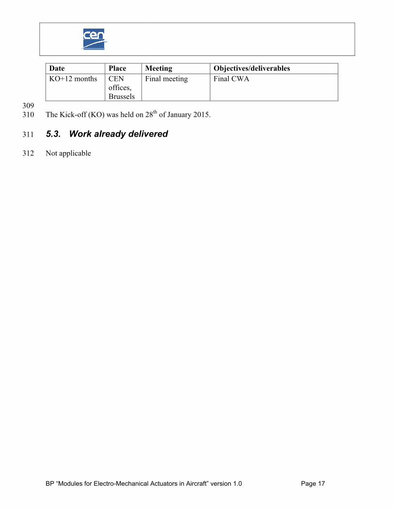
Date Place Meeting Objectives/deliverables
KO2015-01-28
CEN offices, Brussels
Kick-off Meeting Approval of the Business Plan, appointment of Chair and Secretariat
KO+3 months2015-04-22
NLR Amsterdam
1st progress meeting
1st Draft of CWA
KO+9 months TBD 2nd progress meeting
2nd Draft of CWA approval for public comments enquiry (60 days)
BP “Modules for Electro-Mechanical Actuators in Aircraft” version 1.0 Page 17
Date Place Meeting Objectives/deliverables
KO+12 months CEN offices, Brussels
Final meeting Final CWA
309The Kick-off (KO) was held on 28th of January 2015.310
5.3. Work already delivered 311
Not applicable312

BP “Modules for Electro-Mechanical Actuators in Aircraft” version 1.0 Page 18
6. Workshop structure 313
6.1. Workshop Plenary314
The Workshop Plenary is the highest authority of the Workshop. The Workshop Plenary consists 315of representatives from all Workshop members.316
317
6.2. Workshop Chair318
The Workshop Chair is responsible for running of the Workshop. His/her responsibilities include:319
To preside at Workshop Plenary meetings.320
To ensure that the Workshop delivers in line with the Business Plan.321
If deemed necessary, to initiate any required changes to the Business Plan and forward 322issues to the Plenary as appropriate.323
To manage the consensus building process.324
To interface with the Working Groups.325
To manage external liaisons.326
To interface with the CEN regarding strategic directions, problems arising, external 327relationships, etc.328
329
NLR will perform the role of Workshop Chair.330
331
Working Groups and Working Group Chairs/Lead-authors332
Working Groups (WGs) will be established for the development of standardization of selected 333modules and components. The establishment of a WG is during a plenary meeting of the 334Workshop. All participants are invited to contribute their experts to the WG. The Chair of the 335Workshop assigns one of the experts as the Chair of the WG. The Chair of the WG will be 336responsible for the progress of the work in the WG.337
338Definition of Working Groups (WGs) at the Kick-off:339
1. Power Drive Electronics modular architecture guidelines (PDE guidelines): 340o Includes: Internal Standardized Supply Interface (ISSI)341o Lead-author: UTAS France – Serge Bloch342
2. Power Core Module (PCM): 343o Lead-author: Airbus – Marc Fervel344
3. Control & Monitoring Module (CMM): 345o Lead-author: Sagem – Jean-Luc Manca346
4. Protocol for Inverter Control Over LVDS (PICOL) 347o Lead-author: Messier-Bugatti-Dowty – Raphaël Pierra348

BP “Modules for Electro-Mechanical Actuators in Aircraft” version 1.0 Page 19
5. Motor interface including the motor position feedback sensor (Motor interface) 349o Lead-author: UTC – Maamar Benarous350
351
6.3. Workshop Secretariat352
The role of the Secretariat is to co-ordinate the administrative duties involved in the organization 353and implementation of the Workshop, including:354
Business Plan for a CEN Workshop on modules for Electro-Mechanical Actuators in 355aircraft distribution356
Registration, documentation management, meeting organisation support for meetings 357described under 5.2.4 and internal process support358
To act as contact point to respond to any queries of interested parties359
CWA publication and maintenance360
361The Workshop Secretariat will offer the electronic platform for distribution and archiving of the 362Workshop documents. Between meetings, Workshop participants may also use the 363ACTUATION2015 collaborative platform and teleconference services to speed up the consensus 364building on CWA parts.365
366
DIN will perform the role of Workshop Secretariat.367
368
369
6.4. Editors370
GAS-F will provide the technical input for the CWA and will coordinate the contribution of all 371the other ACTUATION2015 industrial participants.372
ARTTIC will take care of the organisation and proof writing of documents. 373
374
375
376

BP “Modules for Electro-Mechanical Actuators in Aircraft” version 1.0 Page 20
7. Resource requirements377
The registration and participation at this CEN Workshop is free of charge for every member of 378the Workshop. All costs related to the participation of interested parties in the Workshop’s 379activities will be borne by themselves.380The cost of the Workshop Secretariat and of the CWA Editors will be supported by 381ACTUATION2015 funding under the work package 72 “Standardisation”. In particular, a sub-382contract to handle the Workshop Secretariat will be given to DIN. The sub-contract will be 383managed by NLR.384
385386

BP “Modules for Electro-Mechanical Actuators in Aircraft” version 1.0 Page 21
8. Related activities, liaisons, etc.387
Not applicable388389390391

BP “Modules for Electro-Mechanical Actuators in Aircraft” version 1.0 Page 22
9. Contact points392
Chairperson:Mr. René EveleensDepartment Manager Aircraft SystemsNational Aerospace Laboratory - NLRAnthony Fokkerweg 21059 CM AmsterdamThe NetherlandsTel: +31 88 511 3600E-mail: [email protected]: www.nlr.nl
Vice-chair:Mr. Henk JentinkAircraft Systems departmentNational Aerospace Laboratory - NLRAnthony Fokkerweg 21059 CM AmsterdamThe NetherlandsTel: +31 88 511 3201E-mail: [email protected]: www.nlr.nl
SecretariatMr. Sebastian EdelhoffProject managerDIN German Institute for Standardization Am DIN-PlatzBurggrafenstrasse 610787 BerlinGermanyTel: +49 30 2601-2453 E-mail: [email protected]: http://www.din.dehttp://www.nl.din.de
CCMC contactMr. Alain DechampsProgramme Manager - Industry, Technology & Infrastructure - StandardsCEN - European Committee for StandardizationCENELEC - European Committee for Electrotechnical StandardizationAvenue Marnix, 17B-1000 BrusselsBelgiumTel: +32 2 550 0867E-mail: [email protected]: www.cencenelec.eu

BP “Modules for Electro-Mechanical Actuators in Aircraft” version 1.0 Page 23
10.Annex A – Description of proposed Work Items393
In the ACTUATION2015 project, a proposal has been prepared for the decomposition of EMAs 394into modules and the decomposition of modules into components. This proposal is depicted in 395Figure 2Fehler! Verweisquelle konnte nicht gefunden werden.. 396
397
Figure 2: ACTUATION2015 definition of EMA modules and components398and possible candidates for standardization (green boxes).399
400The following items have been tentatively identified for standardization:401
1. Power Drive Electronics modular architecture guidelines (PDE guidelines).402
2. Power Core Module (PCM).403
3. Control & Monitoring Module (CMM).404
4. Internal Standardized Supply Interface (ISSI).405
5. Protocol for Inverter Control Over LVDS (PICOL).406
6. Motor interface including the motor position feedback sensor (Motor interface).407
408The following subsections provide descriptions of these items.409
410

BP “Modules for Electro-Mechanical Actuators in Aircraft” version 1.0 Page 24
10.1. Power Drive Electronics modular architecture guidelines411
This standard specification provides guidelines for the design of the Power Drive Electronics 412(PDE). It lists the reference documents applicable to the design of the PDE and describes the key 413PDE features including the external connectors. Those guidelines refer to the set of standard 414module requirements (e.g. PCM, CMM, ISSI, PICOL) to cover the aircraft application range 415addressed in ACTUATION2015.416A variety of other features or elements of the PDE are not covered by standard requirements to 417allow the tailoring of the PDE to a specific application. This includes:418
Casing.419
Thermal management.420
Mechanical support and electrical interconnects between the modules.421
Filter modules.422
Lightening and Electro-Magnetic Protection components.423
Any custom functions that are unique to a particular EMA type.424
10.2. Power Core Module425
Essentially the PCM standard specification consists of two parts:426 An interface control document (ICD) defining the form factor of the board, its connector 427
and pin allocation428 A list of functional and environmental requirements429
The functional description of the PCM can be summarized as follows:430 Provides Motor 3 phase and Solenoid drive power431
o Accepts duty cycle commands via the PICOL bus from CMM-COM module and 432generates the gate drive signals to the switches network433
o Bridge gate drivers provide isolated gate drives to the power switches434o Power switches turn on 270VDC to the motor and solenoid inputs according to 435
gate drive pulse width436 Sends motor phase current, solenoid drive current, input bus voltage and motor position 437
measurement back to CMM modules via PICOL bus438 Provides on-board temperature sensor to be read by CMM-MON439 Provides internal bias voltages from +15V input for proper component operation440 Provides the critical timing control, status acquisition, and external communication 441
interface442
10.3. Control & Monitoring Module443
The CMM-COM and CMM-MON are two copies of the CMM board with different configuration 444and software. Essentially the CMM standard specification consists of two parts:445

BP “Modules for Electro-Mechanical Actuators in Aircraft” version 1.0 Page 25
An interface control document (ICD) defining the form factor of the board, its connector 446and pin allocation447
A list of functional and environmental requirements448
The functional description of the CMM can be summarized as follows:449 Provides primary and secondary µAFDX bus communication to the flight computer 450
system host with transformer isolation451 Address programming via 6 switched ground programming signals452 Provides internal bias voltages from +15VDC input for proper component operation453 Provides sufficient sensor interfaces to meet the need of COM or MON modules for all 454
actuation systems considered in ACTUATION2015 programme455o Temperature sensors (3 max): 4-wire interface to PT100 sensors456o Load/pressure sensors (3 max): bias voltages provided to energize sensors457o xVDT sensors (3 max): 7Vrms excitation at 2kHz provided458o Proximity digital sensor459
Signal processing460o Front end analogue circuitries condition sensor feedbacks for ADC conversions461o Oversees ADC conversions, processes converted data to control actuator 462
operation, and provides operating conditions and health status to system host463 Sends motor and solenoid control information and reads voltage, current, and position 464
status from PCM via high speed PICOL bus465 Provides COM / MON inter-lane communication via communication bus466 Provides Actuator Non-Volatile Memory interface467
10.4. Internal Standardized Supply Interface468
The power supply concept of the PDE may be described as "semi-centralized":469 A first centralized stage of isolated DC/DC down converter is connected to the aircraft 470
low-voltage bus (28VDC) and distributes a standardised regulated +15VDC power supply 471interface to other PDE functions472
Other boards or functions are users of the first stage and generate locally any bias 473voltages necessary for their operation from the +15V input.474
ISSI specification defines the detailed requirements of the first +15VDC centralized stage. Its 475functional scope is as follows:476
Connect the PDE to aircraft low-voltage DC power bus (LVDC)477 Meet all requirements related to DC equipment 478 Supply all internal PDE functions and users that are powered by LVDC479 Provide galvanic insulation between LVDC and ISSI output480 Guarantee the required hold-up/ transparency time during which LVDC voltage can go 481
away but the +15VDC output is expected to remain operational.482 Monitor LVDC bus input voltage and output an under-voltage detection signal to ISSI 483
users.484

BP “Modules for Electro-Mechanical Actuators in Aircraft” version 1.0 Page 26
10.5. Protocol for Inverter Control Over LVDS485
PICOL is the dedicated low-voltage differential signalling (LVDS) digital bus that is used for 486communications (Tx and Rx) between the Command Lane and the PCMs. The objective of 487PICOL digital communication system is to replace the hard-wired interface that the majority of 488systems use to communicate with the power inverter function. The Monitor Lane has a slave 489connection to PICOL that allows it to monitor data that is exchanged between the Command 490Lane and the PCMs.491
The specification describes all PICOL features:492 Single master / multi slaves topology493 PICOL state machine that indicates the current state of the protocol494 Cyclic and deterministic exchanges between modules495 The data exchanged between the modules496 The physical layer of the network497
10.6. Motor interface498
All motors considered in ACTUATION2015 are three-phase star connected brushless permanent 499magnet synchronous motors controlled with 10kHz 270VDC pulse-width modulation (PWM).500
Some of the ACTUATION2015 applications require that the EMA motor provide an 501electromagnetic damping function that is proportional to velocity and permanently engaged. 502Other applications requiring a dual-channel architecture have a dual-winding motor controlled by 503two PDEs operated in an Active/Standby configuration.504
The purpose of the standard motor specification is to define the technical requirements and 505design data applicable for the development of a motor:506
Functional requirements:507o Provide speed and torque as commanded in continuous and short-time duty508o Provide means to monitor rotor position509o Provide means to monitor winding temperature510
Interface requirements511o Single or multiple 3-phase Y-connected (star) brushless permanent magnet 512
synchronous motor, with floating neutral513o Supplied by a HVDC PWM source with a voltage in the range 500-650VDC (full 514
performance) and 400-750VDC (transient)515o Installed as part of an actuator in a non-pressurised, non-temperature controlled 516
area517o Motor feedback position sensor518
Consists of 3 linear Hall-effect probes519 Each linear Hall-effect probe is interfaced to the PCM with a 4-20mA 520
current loop.521o Temperature sensor of PT100 type, 4-wire interface522o Electrical interface523o Mechanical interface.524