center for by -products utilization cbu reports... · for many years questions have been raised...
TRANSCRIPT
Center for By-Products Utilization THE BREAK-OFF TEST METHOD By Tarun R. Naik
Report No. CBU-1990-02 January 1990 Department of Civil Engineering and Mechanics College of Engineering and Applied Science THE UNIVERSITY OF WISCONSIN - MILWAUKEE

THE BREAK-OFF TEST METHOD
by
Tarun R. Naik 1.0 INTRODUCTION For many years questions have been raised regarding concrete quality assurance test methods based upon standard cylinder tests, which measure the potential strength of a concrete batch. In-place concrete strength is not the same as the cylinder concrete strength because the in-place concrete is placed, compacted and cured in a different manner than the cylinder specimen concrete. Determination of accurate in-place strength is critical in form removal and prestress or post-tension force release operations. Also, fast construction techniques and recent construction failures emphasize the need for adopting methods for determining in-p ace concrete strength. Presently several such methods exist and a considerable amount of information is available [1,2,3,4,51. Out of many of these currently available NDT methods, only the Break-Off and the Pull-Out tests measure a direct strength parameters The Break-Off (B.O.) test consists of breaking off an in-place cylindrical concrete specimen at a failure plane parallel to the finished surface of the concrete element. The Break-Off stress at failure can then be related to the compressive or flexural strength of the concrete using a predetermined relationship which relates the concrete strength to the Break-Off strength for a particular source of concrete. The Break-Off test was developed in Norway by-Johansen in 1976 [6]. The B.O. test is still not very widely used in North America. The primary factor in limiting the widespread use of this method being the lack of necessary technical data and experience in North America. Initial work at CANMET in the early 19 80's had indicated a lack of reproducibility in results of this test method (21]. Several papers have been published in Europe about the B.O. method. This chapter provides a more complete and detailed recent information regarding the theory behind the B.O. method, factors affecting this method, and the practical use of this method for laboratory and site investigations. Selected case histories and lab investigations are also included as an attempt to introduce the B.O. method to North America's concrete industry. 2.0 THEORETICAL CONSIDERATIONS The B.O. method is based upon breaking off a cylindrical specimen of in-place concrete. The test specimen has a 55 mm (2.17 in.) diameter and 70 mm (2.76 in.) height. The test specimen is created in the concrete by means of a disposable tubular plastic sleeve, which is cast into the fresh concrete and then removed at the planned time of testing, or by drilling the hardened concrete at the time of the B.O. test. Fig. 2.1 and 2.2 show tubular plastic sleeves and a drill bit, respectively. Both the sleeve and the drill bit are capable of producing a 9.5 mm (3/8 in.) wide groove (counter bore) at the top of the test specimen, Fig. 2.3, for seating the load cell (see Section 3). A force is applied through the load cell by means of a manual hydraulic pump. Figure 2.3 is a schematic of a B.O. concrete cylindrical specimen obtained by inserting a sleeve or drilling a core. The figure also shows location of the applied load at the top of the B.O. test

specimen. In essence, the load configuration is the same as a cantilever beam with circular cross section, subjected @o a concentrated load at it's free end. The force required to Break-Off a test specimen is measured by a mechanical manometer. The Break-Off stress can then be calculated as:
B.O. = M/S
Where:
M = PB.O. * h
h = 65.3 mm
PB.O. Break-Off force at the top
S = ( d)/32
d = 55 mm
In the above simplified formula the manufacturer uses the elementary theory of strength of materials and does not apply the concept of deep beam analysis even though the diameter to length ratio is 1:1.3. This point is being explored (13,14,15). The Break-Off method assumes that the ultimate flexural strength of the concrete is reached at the extreme outside fiber at the base of the B.O. test specimen. In this case, the circular cross-section area would restrict the ultimate fiber stress theoretically to a point, and a crack is initiated at this point. The exact location of the rupture is determined by the loading arrangement, Fig. 2.3, at a distance of 55 mm from the concrete surface. Away from the extreme outside fiber at the base, the stresses successively change in the direction of the neutral axis from tension to compression. The B.0 method is presently the only available test method for directly determining flexural strength of in-place concrete; and, there is a linear relationship between the B.O. flexural strength and modulus of rupture as determined by a beam test [7,8,9,10,11]. 3.0 BREAK-OFF TEST EQUIPMENT The Break-Off tester, Fig. 3.1, consists of a load cell, a manometer, and a manual hydraulic pump capable of breaking a cylindrical concrete specimen having the specified dimensions in Section 2. The load cell has two measuring ranges: low range setting for low strength concrete up to approximately 20 Mpa (3,000 psi) and high range setting for higher strength concrete up to about 60 Mpa (9,000 psi), Fig. 3.2. A tubular plastic sleeve, with internal diameter of 55 mm (2.17 in.) and geometry shown in Fig. 2.1, is used for forming cylindrical specimen in fresh concrete. A sleeve remover, Fig. 3.3, is used for removing the plastic sleeve from the hardened concrete. A diamond tipped drilling bit is used for drilling cores for the B.0 test in hardened concrete, Fig. 2.2. The bit is capable of producing a cylindrical core, along with a reamed ring (counter bore) in the hardened concrete at the top with dimensions similar to that produced by

using a plastic sleeve. The manufacturer also provides a calibrator for calibration and adjustment of the B.0 tester, Fig. 3.4. The procedure of calibrating a B.0 tester is discussed in Section 5.1. 4.0 HISTORICAL BACKGROUND The B.0 method is a relatively new nondestructive test. The first paper was published by Johansen in 1976 [6] and the research work was done at the Norwegian Technical University In 1917, researchers at the NTH and the Research Institute for Cement & Concrete in Norway, developed and patented the Break-Off tester as a method for determination of compressive strength of in-place concrete. Johansen [61 in his first paper indicated the main use of this method as a very efficient way of determining the in-place concrete strength for form removal. In 1979, Johansen and Dahl-Jorgensen published a paper an the use of the B.O. method to detect variation in the concrete strength and curing conditions [12). In their research a comparison was made between the B.O. method and the Pull-Out test method. The compressive strength of cores obtained from the B.O. tests and the standard cube compressive strength was also compared. They concluded that the Pull-Out test method and the core compressive strength values obtained from the B.O. tests have a better ability to differentiate between concrete qualities than the cube test. On the other hand, the BO. test results and the core compressive strength results demonstrated their ability in detecting variation in curing conditions, while the Pull-Out test method did not register some of the curing differences demonstrated by the B.O. and the core results. Also, in 1979, Johansen published another paper (9) on the use of the B.O. method, with a particular reference to its application to airport pavements made of vacuum concrete. The author concluded that the variation of the concrete strength detected by the B.O. method is of the same order of magnitude as the variation detected by conventional flexural beam test. Furthermore, the B.O. strength was about 30% higher than the conventional modulus of rupture because of deviations in the load configurations and geometric parameters between the two test methods. A high sensitivity of the B.C. method to sense the influence of the ambient air temperature on early strength was also indicated in this paper. A good relationship was obtained between B.O. test readings and the compressive strength of the concrete obtained by standard cube testing. In 1980, Byfors tested concrete at early ages, using the Break-Off method [7]. In his research Byfors tested concretes with different water to cement ratios, and different aggregate sizes 8, 16 and 32 mm (5/16", 5/8" and 1-1/4"). The conclusion was that the B.O. method is well suited to detecting low strength concrete made with different sizes of coarse aggregates. After modifications to the B.O. tester, Dahl-Jorgensen published two reports on the use of the B.O. method [12,16]. In this study, he investigated the use of the new equipment in testing epoxy to concrete bond strength, and compared the results of the B.O. and the Pull-Out methods. He concluded that the B.O. test provided results with smaller variations between individual tests than the Pull-Out method. Also, fewer tests were rejected for the B.D. method compared to the Pull-Out method. Nishikawa published his work in 1983 [101, after conducting very limited laboratory research on the use of the B.O. method for determining flexural strength of concrete. He concluded that the relationship between the B.O. test results and cylinder compressive

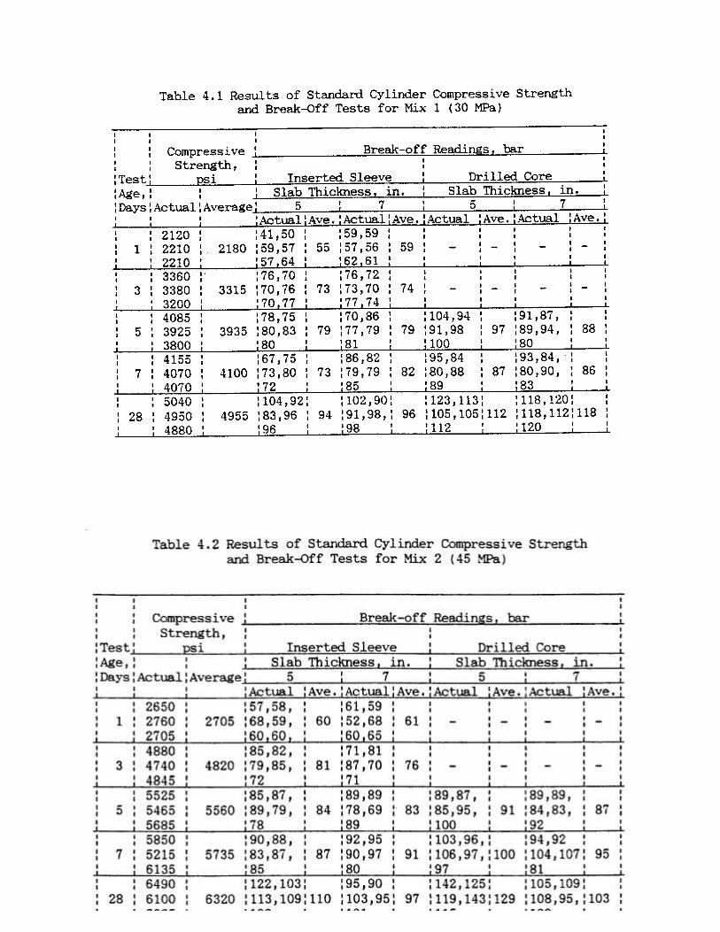
strength tests was complex and of little practical value. Therefore, no attempt was made to correlate these two test results. This is, of course, contrary to all other published information about the B.O. method. He further concluded that the change in the shape of the aggregates was not sensed by the B.O. method. These two conclusions are further discussed in Section 6. Nishikawa indicated a relatively high within test variation for the inserted sleeve B.O. tests as compared to cylinder and beam tests. With respect to other variables, he found that the B.O. test results were affected by water-cement ratio, age, curing conditions, and cement type. In 1984 Carlsson, Eeg, and Jahren published a paper on field experiences with the use of the B.0 tester [171. Six case histories were discussed. The authors concluded a trend towards greater acceptance of the B.O. test method in the field. In 1987 another very limited exploratory investigation was done by Barker and Ramirez [18]. The Scancem version of the tester was used. They investigated the effects of the water to cement ratio, maximum aggregate size, and aggregate shape. They indicated a relatively low within test variation of the method of 6.1%, while that of the cylinder and beam tests were 7.6% and 4.6%, respectively. A regression analysis was performed between 13.0. test results and the cylinder test results. Good correlation was obtained and a detailed statistical study was performed on the effects of different parameters on the B.O. compressive and flexural strengths relation. Also in 1987, Naik, Hassaballah and Salameh conducted a comprehensive laboratory investigation at the University of Wisconsin-Milwaukee [13,14,15]. They were the first to study the effects of the method of obtaining the B.O. test specimen, either by inserting a plastic sleeve in fresh concrete or by drilling a core after the concrete had hardened. Furthermore, they investigated the applicability of the B.O. test for high strength concrete. The strengths investigated were 45 and 55 MPa (6,000 and 8,000 psi), along with 30 MPa (4,000 psi,). They also studied the effect of aggregate shape and slab thickness on the B.O. test results. A total of 524 B.O. tests were performed. They concluded that B.O. readings for crushed aggregates were on the average 10% higher than that for the rounded aggregates. Also, the B.O. test is less variable for crushed aggregate concrete. They also stated that the drilled core B.O. test results were on the average about 9% higher than the inserted sleeve B.O. test results. According to Naik, Hassaballah and Salameh the drilled core test method is preferable, although both methods of obtaining the B.O. test specimen showed good correlation with the compressive strength of the in-place concrete, and also yielded equally consistent B.O. test results, see Tables 4.1, 4.2 and 4.3, and Figures 4.1 and 4.2. They have discussed some of the difficulties encountered in inserting sleeves in harsh concrete or concrete with high amounts of bleeding. Additional statistical analysis is being performed on the large amount of data that this investigation has yielded.

5.0 TEST PROCEDURE 5.1 Inserting Sleeves in Fresh Concrete Sleeves should be at center to center and edge distance of minimum 150 mm (6 in.). They are best pushed in-place by a rocking and twisting action, Fig. 5.1.1. Concrete inside the sleeve and the top of plastic sleeve itself should then be tapped by fingers to insure good compaction for the B.O. specimen. Sleeves should then be moved gently up and down in-place and brought to the same level as the concrete surface at its final position. For stiff mixes, i.e. low slump concrete-, a depression may occur within the confines of the sleeve during the insertion process. In such cases the sleeve should be filled with additional concrete tapped with fingers, and slightly jiggled from side to side. (On the -other hand, for wet, high slump mixes, the sleeve may move upward due to bleeding. For such cases, sleeves should be gently pushed back in-place, as necessary, to the level of the finished concrete surface. Some times this process may have to be repeated until the uplift movement stops after the initial setting has occurred. A small weight may be placed on the sleeve in order to prevent its upward movement. Heavy grease, or other similar material, should be used to lubricate the plastic sleeves for easier removal after the concrete hardens. 5.2 Preparation for Core Drilling from Hardened Concrete

The finished concrete surface should be evaluated for sufficient smoothness in order Io fix the vacuum plate of the core drilling machine. The core barrel should be perpendicular to the concrete surface at all times. The drilling process should be continued to the full depth required to produce a cantilever cylindrical core of 70 mm (2-76 in.) length, with a groove at the top of the core for setting the B.O. tester load cell. A slightly longer drilled core will not affect the B.O. reading, while a slightly shorter drilled core will affect the B.O. reading, Fig. 5.2.1. 5.3 Conducting the B.O. Test At the time of the B.O. test, remove the inserted plastic sleeve by means of the key supplied with the tester, Fig. 3.3. Leave the plastic ring in-place. Remove loose debris from around the cylindrical slit and the top groove, see Fig. 2.3. Select the desired range setting and place the load cell in the groove on the top of the concrete surface so that the load is applied according to Fig. 2.3. The load should be applied to the test specimen at a rate of approximately one stroke of the hand pump per second. This rate is equivalent to about 0.5 MPa (7O psi) of hydraulic pressure per second. After breaking off the test specimen, record the B.O. manometer reading. This manometer reading can then be translated to the concrete strength using curves relating the B.C. reading to the desired concrete strength (i.e., flexural and/or compressive). 5.4 The B.O. Tester Calibration Procedure The B.O. tester should be calibrated preferably each time before use, otherwise periodically. To calibrate the tester, follow the following steps:
(1) Set the calibrator gauge to zero. (2) Place the calibrator in the load cell, (Fig. 5.4.1). (3) Set the load cell on the high setting. (4) Apply the load to the calibrator by pumping the handle until the load cell manometer
reading is 100. (5) Record the dial gauge reading and compare it with the expected value obtained from the
manufacturers calibration chart, Fig. 5.4.2. The dial gauge value should be within 4% of the manufacturer's chart value.
(6) Repeat the above procedure for the low range setting. Adjustment of the B.O. tester is necessary if error in the reading obtained is greater than +4 percent of the expected value from the chart. For a well calibrated tester, the needle on the manometer should move 5 bars per one hand stroke, while the first and/or second strokes might not move it that much. A good rate of applying the load would be one stroke per second. 5.5 Developing a Correlation Curve The B.O. manufacturer provides correlation curves relating the B.O. reading and the compressive strength of the standard 150 x 300 mm cylinders and 150 mm cubes. Figure 5.5.1 is the manufacturer's curves for the high range setting of the load cell, while Fig. 5.5.2 is for the low range setting (see Section 3). This correlation is nonlinear and was empirically derived-. The curve relating the B.O. reading and the compressive strength is concaved upward. This seems to indicate that the B.O. tester is less sensitive for higher concrete strengths. It should be noted that the manufacturers curves consider many variables. However, knowing that concrete itself has inherent variability, a user should develop his own correlation curves for a particular concrete batch. Developing correlation curves for different types of concrete would efficiently increase the accuracy and dependability of the method in predicting the in-place strength.
The following precautions should be taken when developing data for correlations.
(1) Keep the center-to-center and the edge distances of at least 150 mm (6 in.) in the process of inserting sleeves or drilling B.O. cores.
(2) Obtain a minimum of five B.O. readings and three corresponding standard strength test specimens values, i.e., cylinders for compressive strength, and beams for flexural strength, for each test age.
(3) An average of the five B.O. readings and the average of the three standard cylinder test results represent one point on the graph relating the B.D. reading to the desired standard strength of the concrete.
(4) Cover the range of concrete strengths expected in the project, at early as well as at later ages, such as 1,3,5,7,14, and 28 days.
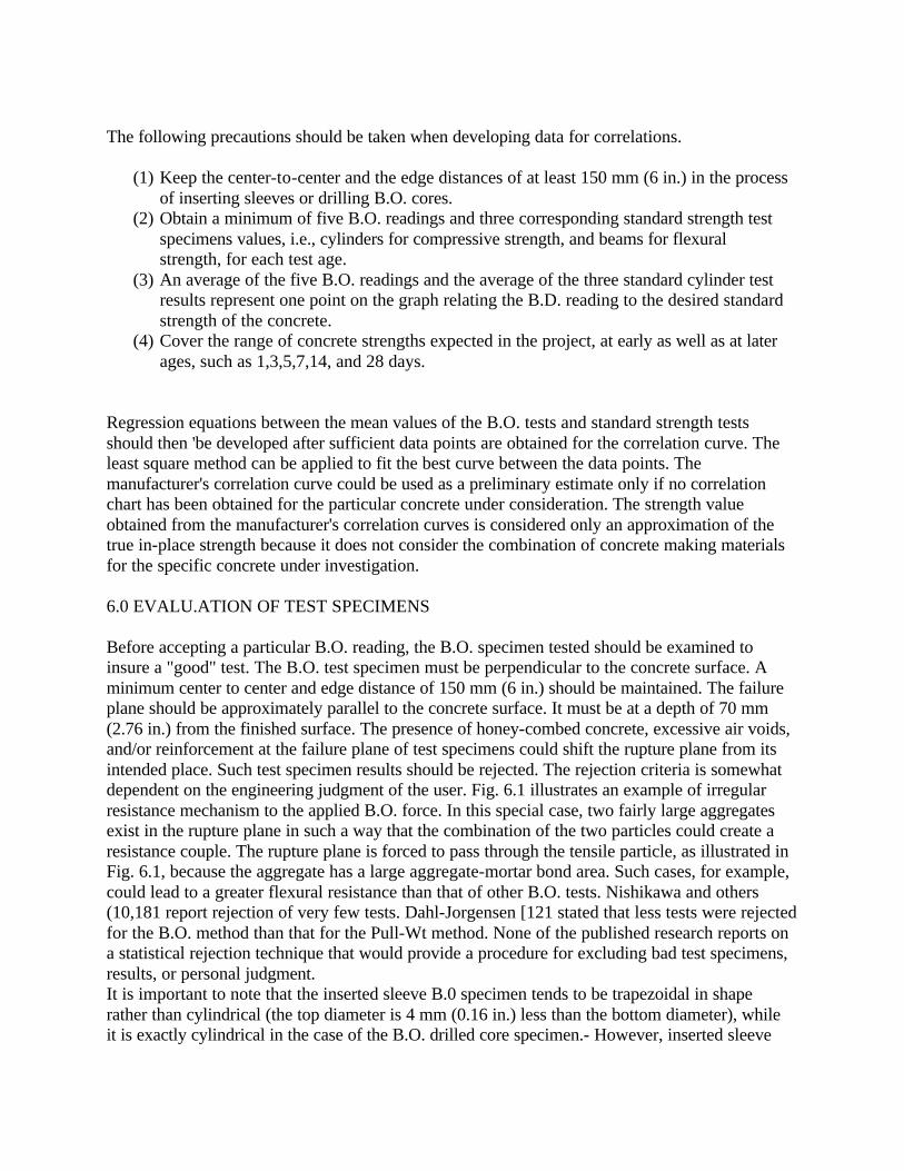
Regression equations between the mean values of the B.O. tests and standard strength tests should then 'be developed after sufficient data points are obtained for the correlation curve. The least square method can be applied to fit the best curve between the data points. The manufacturer's correlation curve could be used as a preliminary estimate only if no correlation chart has been obtained for the particular concrete under consideration. The strength value obtained from the manufacturer's correlation curves is considered only an approximation of the true in-place strength because it does not consider the combination of concrete making materials for the specific concrete under investigation. 6.0 EVALU.ATION OF TEST SPECIMENS Before accepting a particular B.O. reading, the B.O. specimen tested should be examined to insure a "good" test. The B.O. test specimen must be perpendicular to the concrete surface. A minimum center to center and edge distance of 150 mm (6 in.) should be maintained. The failure plane should be approximately parallel to the concrete surface. It must be at a depth of 70 mm (2.76 in.) from the finished surface. The presence of honey-combed concrete, excessive air voids, and/or reinforcement at the failure plane of test specimens could shift the rupture plane from its intended place. Such test specimen results should be rejected. The rejection criteria is somewhat dependent on the engineering judgment of the user. Fig. 6.1 illustrates an example of irregular resistance mechanism to the applied B.O. force. In this special case, two fairly large aggregates exist in the rupture plane in such a way that the combination of the two particles could create a resistance couple. The rupture plane is forced to pass through the tensile particle, as illustrated in Fig. 6.1, because the aggregate has a large aggregate-mortar bond area. Such cases, for example, could lead to a greater flexural resistance than that of other B.O. tests. Nishikawa and others (10,181 report rejection of very few tests. Dahl-Jorgensen [121 stated that less tests were rejected for the B.O. method than that for the Pull-Wt method. None of the published research reports on a statistical rejection technique that would provide a procedure for excluding bad test specimens, results, or personal judgment. It is important to note that the inserted sleeve B.0 specimen tends to be trapezoidal in shape rather than cylindrical (the top diameter is 4 mm (0.16 in.) less than the bottom diameter), while it is exactly cylindrical in the case of the B.O. drilled core specimen.- However, inserted sleeve

B.O. specimen reading is not affected by the trapezoidal shape because the bottom diameter at the failure plane always remains 55 mm (2.17 in.) [13,14,15). In evaluating inserted sleeve specimens, it is also reported that the drilled core specimens give higher readings than the inserted sleeve specimens [13,14,151. This is because in the case of the inserted sleeve specimens, the accumulation of bleed water under the bottom edge of the sleeve would tend to create a weaker zone of concrete exactly where the failure plane for the B.O. inserted sleeve test occurs. 7.0 APPLICATIONS The potential of the B.O. test is promising. This method can be used both for quality control and quality assurance. The most practical use of the B.O. test method is for determining the time for safe form removal, and the release time for transferring the force in pre-stressed or post-tension members. The B.O. method can also be used to evaluate existing structures. It has been reported that the B.C. test provides a more effective way in detecting curing conditions of concrete than the Pull-out and the standard cylinder tests (7,8,9,12,16). In 1982 the B.0 tester was used to control the time for safe form removal for a new "Bank of Norway" building and an apartment building in Oslo. In 1983, the B.O. tester was used in England. Recently the B.O. tester has been used by the Norwegian Contractors Company, which is responsible for building off-shore platforms for the oil fields in the North Sea. The B.O. method can also be used to measure the bonding strength of overlays or the bonding between concrete and epoxy, but this usage has not been applied in the field [12,16]. 8. 0 ADVANTAGES AND LIMITATIONS The main advantage of the B.O. test is that it measures the in-place concrete (flexural) strength. The equipment is safe and simple; and, the test is fast to perform, requiring only one exposed surface. The B.O. test does not need to be planned in advance of placing the concrete because drilled B.O. test specimens can be obtained. The test is reproducible to an acceptable degree of accuracy and does correlate well with the compressive strength of concrete. Two limitations for the B.O. test equipment are worth noting: (1) the maximum aggregate size; and, (2) the minimum member thickness for which it can be used. The maximum aggregate size is 19 mm (3/4 in.) and the minimum member thickness is 100 mm (4 inches). However, the principle of the method can be applied to accommodate larger aggregate sizes or smaller members. The major disadvantage of the B.O. test is that the damage to the concrete member must be repaired if the member is going to be visible. However, this test is nondestructive since the tested member need not be discarded. 9.0 STANDARDIZATION OF THE B.O. METHOD Recently the B.0 method was standardized in England (3], Norway [191, and Sweden [201. It is also undergoing the process of standardization in the United States.

10.0 REFERENCES
(1) Malhotra, V., "Testing Hardened Concrete: Nondestructive Methods," ACI Monograph No. 9, 1976, 188 pages.
(2) Jones, P.., " A Review of Nondestructive Testing of Concrete," Proceedings, Symposium an Nondestructive Testing of Concrete and Timber, Institute of Civil Engineers, London, June 1969, pp. 1-7.
(3) British Standard, B.S. 1881, Part 201, 1986, page 17. (4) "Methods of Mechanical Nondestructive Determination of Probable Compressive
Strength of Concrete," Bulgarian National Standard 3816 - 65. (5) Vossitch, Paule, "Outline of the Various Possibilities of Nondestructive Mechanical
Tests on Concrete," Proceedings, International Symposium on Nondestructive Testing of Materials and Structures, V. 2, Paris, 1959, pp. 30-39.
(6) Johansen, R., "A New Method for Determination of In-Place Concrete Strength of Form Removal," First European Colloquium on Construction Quality Control, Madrid, Spain, March 1976, 12 pages.
(7) Byfors, J., "Plain Concrete at Early Ages," Swedish Cement and Concrete Research Institute, Report No. Facks-10044, Stockholm Sweden, 1980, 19 pages.
(8) Dahl-Jorgensen, E., "In-situ Strength of Concrete, Laboratory and Field Tests," Cement and Concrete Research Institute, The Norwegian Institute of Technology, Report No. STF 65A, Trondheim, Norway, June 1982.
(9) Johansen, R., "In-situ Strength of Concrete," The Break-Off Method, Concrete International, Sept. 1979, pp. 45-52.
(10) Nishikawa, A., "A Nondestructive Testing Procedure for In-Place Evaluation of Flexural Strength of Concrete," Report No. JHRP 83-10, Joint Highway Research Project, School of Civil Engineering, Purdue University, West Lafayette, Indiana, 1983, 65 pages.
(11) Smith, L., "Evaluation of the Scancem Break-Off Tester," Ministry of Works and Development, Central Laboratories, Report No. 86/6, New Zealand, 1986, 14 pages.
(12) Dahl-Jorgensen, E., and Johansen, R., "General and Specialized use of the Break-Off Concrete Strength Test Method," ACI, SP 82-15, 1984, pp. 294-308.
(13) Hassaballah, A., "Evaluation of In-Place Crushed Aggregates Concrete by the Break--Off Method," Civil Engineering Department, University of Wisconsin-Milwaukee, Dec. 1987.
(14) Salameh, Z., "Evaluation of In-Place Rounded Aggregates Concrete by the Break-off Method," Civil Engineering Department, University of Wisconsin-Milwaukee, Dec. 1987.
(15) Naik, T.R., Salameh, Z., and Hassaballah, A., "Evaluation of In-Place Strength of Concrete by the Break--Off Method," Department of Civil Engineering and Mechanics, The University of Wisconsin-Milwaukee, Milwaukee, WI, March 1988.
(16) Dahl-Jorgensen, E., "Break-Off and Pull-Out Methods for Testing Epoxy-Concrete Bonding Strength," Project No. 160382, The Foundation of Scientific and Industrial Research of the Norwegian Institute of Technology, Torndheim, Norway, Sept. 1982, 15 pages.
(17) Carlsson, M., Eeg, I., and Jahren, P., "Field Experience in the Use of Break--Off Tester," ACI, SP 82-14, 1984, pp. 278-292.

(18) Barker, M., and Ramirez, J., "Determination of Concrete Strengths Using Break-Off Tester," School of Civil Engineering, Purdue University, West Lafayette, Indiana, 1987, 114 pages.
(19) Nordtest Method NTBUILD 212," Edition 2, Approved 1984-05, 5 pages. (20) Swedish Standard, SS 137239, Approved 1983-06, 3 pages. (21) Personal Communication from V.M. Malhotra, CANMET, Ottawa, Ontario, Canada,
1984. LIST OF FIGURES 2.1 Tubular Plastic Sleeves for Inserting in Fresh Concrete for the B.C Test 2.2 Core Drill Bit for Drilling a Core for 13.0. Testing of Existing Concrete Element 2.3 Schematic of a Concrete Cylindrical Specimen Obtained by Inserting Sleeve or Drilling a-Core, and Location of Applied Load 3.1 The B.O. Test Equipment: (1) Load Cell, (2) Manometer, and (3) Hydraulic Hand Pump 3.2 Low and High Range Settings of the B.O. Tester Load Cell 3.3 Sleeve Remover 4.1 The B.O. Tester Calibrator Plots of Regression Equations for Inserted Sleeve Specimens for
Mix 1,2, and 3. 4.2 Plots of Regression Equations for Drilled Core Specimens for Mix 1, 2 and 3. 5.1.1 Inserting Sleeve by Rocking Action 5.2.1 The B.O. Drilled Specimen Dimensions 5 5.4.1 Calibrator Placed in the Load Cell 5.4.2 Calibrator Chart as Provided by the Manufacturer 5.5.1 B.O. Manometer Reading vs. Concrete Compressive Strength as Provided by the Manufacturer, for the High Range Setting 5.5.2 B.O. Manometer Reading vs. Concrete Compressive Strength as Provided by the Manufacturer, for the Low Range Setting 6.1 Rejected B.D. Specimen Due to Presence of Aggregate(s) in the Failure Plane.

Fig. 2.1 Tubular Plastic Sleeves for Inserting in Fresh Concrete for the B. O. Test
Fig. 2.2 Core Drill Bit for Drilling a Core for B.O. Testing of Existing Concrete Element

Fig. 2.3 Schematic of a Concrete Cylindrical Specimen Obtained by Inserting a Sleeve or Drilling a Core, and Location of Applied Load

Fig 3.1 The B.O. Test Equipment: (1) Load Cell, (2) Manometer, and (3) Hydraulic Hand Pump
Fig 3.2 Low and High Range Setting of the B.O. Tester Load Cell

Fig. 3.3 Sleeve Remover
Fig. 3.4 The B.O. Tester Calibrator

Fig. 4.1 Plots of Regression Equations for Inserted Sleeve Specimens for Mix 1, 2, and 3.

Fig. 4.2 Plots of Regression Equations for Drilled Core Specimens for Mix 1, 2, and 3.

Fig. 5.1.1 Inserting Sleeve by Rocking Action
Fig 5.2.1 The B.O. Drilled Specimen Dimensions

Fig 5.4.1 Calibrator Placed in the Load Cell
Fig 5.4.2 Calibrator Chart as provided by the Manufacturer
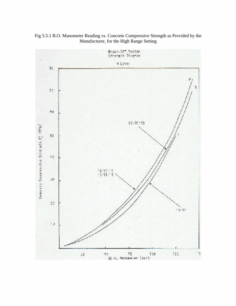
Fig 5.5.1 B.O. Manometer Reading vs. Concrete Compressive Strength as Provided by the
Manufacturer, for the High Range Setting
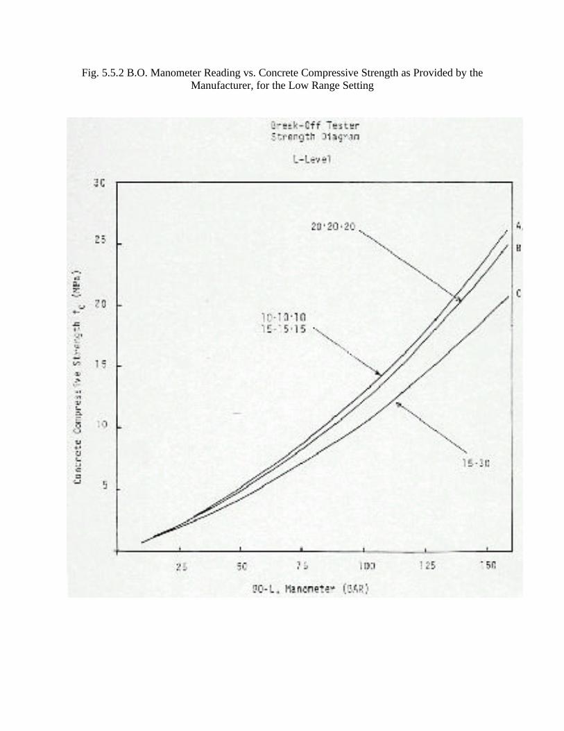
Fig. 5.5.2 B.O. Manometer Reading vs. Concrete Compressive Strength as Provided by the Manufacturer, for the Low Range Setting

Fig 6.1 Rejected B.O. Specimen Due to Presence of Aggregate(s) in the Failure Plane.