central heating for marine aquarium tanks · central heating for marine aquarium tanks robert c....
TRANSCRIPT
www.csiro.au
Central heating formarine aquarium tanks
Robert C. Pendrey
CSIRO Marine and Atmospheric Research Paper 006
April 2006
�������� ����������
������������ �����
����������� ������
��� ��������
����������
������
�������
���� ��������
����
�������

Central heating for marine aquarium tanks
Robert C. Pendrey
CSIRO Marine and Atmospheric Research Paper 006 April 2006
Pendrey, R. C., 1950- . Central heating for marine aquarium tanks.
Bibliography.
Includes index.
ISBN 1 921061 35 9.
1. Marine aquariums.
2. Marine aquarium fishes - Housing - Environmental engineering. I. CSIRO. Marine and Atmospheric Research.
II. Title. (Series : CSIRO Marine and Atmospheric Research paper; 6).
597.073
Enquiries should be addressed to:
Robert C. Pendrey
CSIRO Marine and Atmospheric Research
PO Box 120 Cleveland, Queensland 4163, Australia
Phone (07) 3826 7109 Fax (07) 3826 7222
Email: [email protected]
Important Notice
© Copyright Commonwealth Scientific and Industrial Research Organisation
(‘CSIRO’) Australia 2005
All rights are reserved and no part of this publication covered by copyright may be reproduced or copied in
any form or by any means except with the written permission of CSIRO.
The results and analyses contained in this Report are based on a number of technical, circumstantial or
otherwise specified assumptions and parameters. The user must make its own assessment of the suitability
for its use of the information or material contained in or generated from the Report. To the extent permitted by
law, CSIRO excludes all liability to any party for expenses, losses, damages and costs arising directly or
indirectly from using this Report.
Use of this Report
The use of this Report is subject to the terms on which it was prepared by CSIRO. In particular, the Report may
only be used for the following purposes.
this Report may be copied for distribution within the Client’s organisation;
the information in this Report may be used by the entity for which it was prepared (“the Client”), or by the
Client’s contractors and agents, for the Client’s internal business operations (but not licensing to third
parties);
extracts of the Report distributed for these purposes must clearly note that the extract is part of a larger
Report prepared by CSIRO for the Client.
The Report must not be used as a means of endorsement without the prior written consent of CSIRO.
The name, trade mark or logo of CSIRO must not be used without the prior written consent of CSIRO.

CONTENTS
Abstract . . . . . . . . . . . . . . . . . . . . . . . . . . . . . . . . . . . . . . . . . . . . . . . . . . . . . . . . . . . . . . . . . . . . . . . . . . . . . . . . . . . . . . . . . . . . . . . . . . . . 1
1. Introduction . . . . . . . . . . . . . . . . . . . . . . . . . . . . . . . . . . . . . . . . . . . . . . . . . . . . . . . . . . . . . . . . . . . . . . . . . . . . . . . . . . . . . . 1
2. Design . . . . . . . . . . . . . . . . . . . . . . . . . . . . . . . . . . . . . . . . . . . . . . . . . . . . . . . . . . . . . . . . . . . . . . . . . . . . . . . . . . . . . . . . . . . . . . 2
2.1 Hot fresh water supply . . . . . . . . . . . . . . . . . . . . . . . . . . . . . . . . . . . . . . . . . . . . . . . . . . . . . . . . . . . . . . . . . . . . . . . . 2
2.2 Heat transfer . . . . . . . . . . . . . . . . . . . . . . . . . . . . . . . . . . . . . . . . . . . . . . . . . . . . . . . . . . . . . . . . . . . . . . . . . . . . . . . . . . . . . . 3
2.2.1 Heating of tank arrays . . . . . . . . . . . . . . . . . . . . . . . . . . . . . . . . . . . . . . . . . . . . . . . . . . . . . . . . . . . . . . . . . . . . . . . . 3
2.2.2 Heating of individual tanks with high exchange rates . . . . . . . . . . . . . . . . . . . . . . . . . . . . . . . 3
2.2.3 Heating of individual tanks with low exchange rates . . . . . . . . . . . . . . . . . . . . . . . . . . . . . . . . 3
2.2.4 Heating of non-flow through tanks . . . . . . . . . . . . . . . . . . . . . . . . . . . . . . . . . . . . . . . . . . . . . . . . . . . . . . . 3
3. Small heat-exchangers . . . . . . . . . . . . . . . . . . . . . . . . . . . . . . . . . . . . . . . . . . . . . . . . . . . . . . . . . . . . . . . . . . . . . . . . 4
4. Discussion . . . . . . . . . . . . . . . . . . . . . . . . . . . . . . . . . . . . . . . . . . . . . . . . . . . . . . . . . . . . . . . . . . . . . . . . . . . . . . . . . . . . . . . . 4
5. Conclusion . . . . . . . . . . . . . . . . . . . . . . . . . . . . . . . . . . . . . . . . . . . . . . . . . . . . . . . . . . . . . . . . . . . . . . . . . . . . . . . . . . . . . . . . 5
Acknowledgements . . . . . . . . . . . . . . . . . . . . . . . . . . . . . . . . . . . . . . . . . . . . . . . . . . . . . . . . . . . . . . . . . . . . . . . . . . . . 6
References . . . . . . . . . . . . . . . . . . . . . . . . . . . . . . . . . . . . . . . . . . . . . . . . . . . . . . . . . . . . . . . . . . . . . . . . . . . . . . . . . . . . . . . . 6
Figures . . . . . . . . . . . . . . . . . . . . . . . . . . . . . . . . . . . . . . . . . . . . . . . . . . . . . . . . . . . . . . . . . . . . . . . . . . . . . . . . . . . . . . . . . 7 – 9


1
Central heating for marine aquarium tanks
Robert C. Pendrey Abstract For work involving aquatic organisms there is a need to have a simple cost-effective way to control the temperature in a variety of tanks of different shapes and sizes. To do this we designed and installed a versatile, low maintenance system to supply heat to a range of tanks used in an experimental facility. It has been used to control the temperature in individual tanks from 60 litres to 10 tonnes with water exchange rates from zero to 4 l min -1. The system has also been used to supply heat to raceways and multiple-tank arrays. The system is based on several designs of counter flow heat exchangers and external heating coils. The working fluid is 55°C freshwater, recirculated through two 75 kW conventional natural-gas boilers. Electrically operated valves control the supply of hot fresh water to heat exchangers or external coils at each tank site. A major benefit of using the fresh water to heat the seawater in this system is that the control valves only operate on the hot fresh water and are protected from fouling and corrosion. The external coils of polythene pipe are used to heat cylindrical tanks that are operated with little or no water exchange. Performance data is provided for one polythene heat exchanger configuration. During 8 years of continuous operation the system has provided temperature control for over 200 tanks plus two raceways at one time with total seawater use of over 4 l sec-1. It has proved safe, reliable, adaptable and easy to operate. Keywords: Seawater; Heating; Heat exchangers. 1. Introduction For year round experimental work on aquatic organisms it is necessary to control the water temperature in the tanks. For tropical organisms this usually involves heating the water and avoiding rapid changes in temperature (Huguenin and Holt 1989). While there are many ways to do this there is a need for an approach that is energy efficient, allows independent temperature control for tanks and is, at the same time, safe and reliable when operating on a large scale. For small operations it is most convenient to use electric immersion heaters in each tank. On a large scale it is expensive to install electric heaters and peak load electricity charges can make them very expensive to run. There are also dangers associated with having high voltage electricity associated with seawater tanks. A conventional, cost effective way of heating the water is to use an efficient central boiler fired by gas or oil, usually isolated from the tank water by a heat exchanger, to heat a reserve of water. This heated water is then circulated at a constant rate through an array of tanks. (Ricque et al 1993). However unless all tanks are limited to the same flow rate and temperature, it may then be necessary to either mix this water with cooler water or alter the flow rates to give any other desired temperatures in the tanks.
2
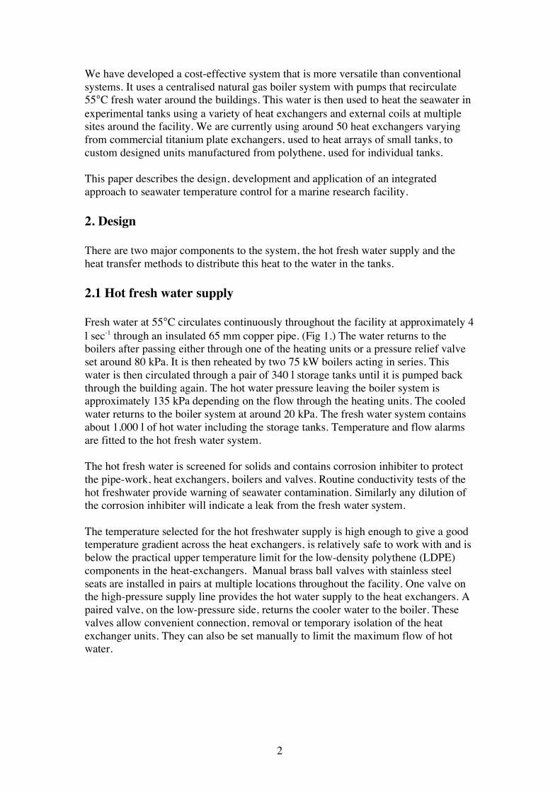
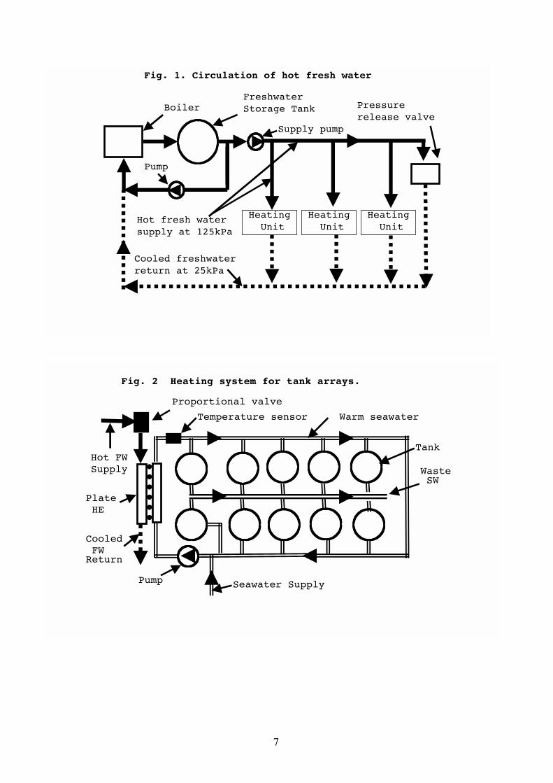
We have developed a cost-effective system that is more versatile than conventional systems. It uses a centralised natural gas boiler system with pumps that recirculate 55°C fresh water around the buildings. This water is then used to heat the seawater in experimental tanks using a variety of heat exchangers and external coils at multiple sites around the facility. We are currently using around 50 heat exchangers varying from commercial titanium plate exchangers, used to heat arrays of small tanks, to custom designed units manufactured from polythene, used for individual tanks. This paper describes the design, development and application of an integrated approach to seawater temperature control for a marine research facility. 2. Design There are two major components to the system, the hot fresh water supply and the heat transfer methods to distribute this heat to the water in the tanks. 2.1 Hot fresh water supply Fresh water at 55°C circulates continuously throughout the facility at approximately 4 l sec-1 through an insulated 65 mm copper pipe. (Fig 1.) The water returns to the boilers after passing either through one of the heating units or a pressure relief valve set around 80 kPa. It is then reheated by two 75 kW boilers acting in series. This water is then circulated through a pair of 340 l storage tanks until it is pumped back through the building again. The hot water pressure leaving the boiler system is approximately 135 kPa depending on the flow through the heating units. The cooled water returns to the boiler system at around 20 kPa. The fresh water system contains about 1,000 l of hot water including the storage tanks. Temperature and flow alarms are fitted to the hot fresh water system. The hot fresh water is screened for solids and contains corrosion inhibiter to protect the pipe-work, heat exchangers, boilers and valves. Routine conductivity tests of the hot freshwater provide warning of seawater contamination. Similarly any dilution of the corrosion inhibiter will indicate a leak from the fresh water system. The temperature selected for the hot freshwater supply is high enough to give a good temperature gradient across the heat exchangers, is relatively safe to work with and is below the practical upper temperature limit for the low-density polythene (LDPE) components in the heat-exchangers. Manual brass ball valves with stainless steel seats are installed in pairs at multiple locations throughout the facility. One valve on the high-pressure supply line provides the hot water supply to the heat exchangers. A paired valve, on the low-pressure side, returns the cooler water to the boiler. These valves allow convenient connection, removal or temporary isolation of the heat exchanger units. They can also be set manually to limit the maximum flow of hot water.

3
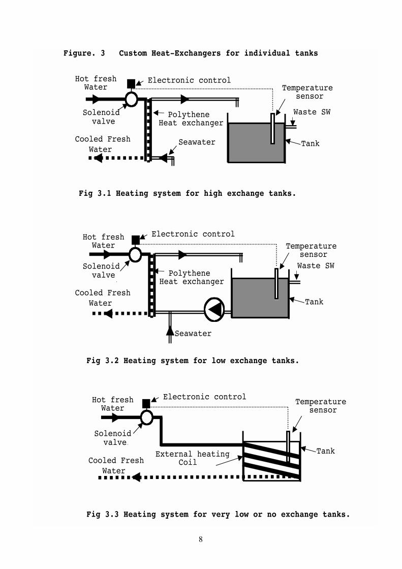
2.2 Heat transfer We use four different heating systems depending on the tank sizes and exchange rates. 2.2.1 Heating of tank arrays Commercial Titanium plate heat exchangers were used to heat arrays of up to 48 tanks using small ring main systems. (Fig. 2.) In these systems all the tanks were maintained at the same temperature and flow rate. The seawater is pumped through a heat exchanger around the pipe work to the tanks so that any unused water returns to the pump at the start of the ring.(Fig 2.) If the flow rate through the ring is set correctly only a small amount of unused water will return to the pump to be reheated so the water in the ring is almost completely exchanged. Each ring has a microcomputer based, temperature-indicating controller which adjusts the position of a proportional valve on the hot fresh water supply. The microcomputer control shows the operating temperature and also has alarm functions. 2.2.2 Heating of individual tanks with high exchange rates Small heat exchangers were used for flow through tanks where the exchange rate was high enough that the temperature of the exchange water did not need to be too hot. (Fig 3.1). We designed our own small polythene heat exchangers for independent temperature control for individual tanks. A thermostat, with a sensor in the tank, simply turns on and off a plastic 12-volt solenoid valve on the hot fresh water supply. When setting up, the flow rate of the hot water may be adjusted manually, with the solenoid valve open, to produce stable temperature control. We used these small heat exchangers in line with the make-up water on tanks from 300 l to 10 tonne capacity 2.2.3 Heating of individual tanks with low exchange rates For hot tanks with low exchange rates it is not practical to supply all the heat through the exchange water as it would need to be too hot. To overcome this problem, filtered water from the tank was continuously recirculated with a pump at 2 l/m through the heat exchanger (Fig 3.2). It is suited to rectangular tanks where wrapping external heating coils would be impractical. 2.2.4 Heating of non-flow through tanks Some 60 l circular polythene tanks where no water was being exchanged were fitted with an external-heating coil. (Fig.3.3) These coils consist of 10 metres of 13 mm LDPE pipe tightly wrapped around the tanks. Each tank has a sensor and solenoid control valve.
4
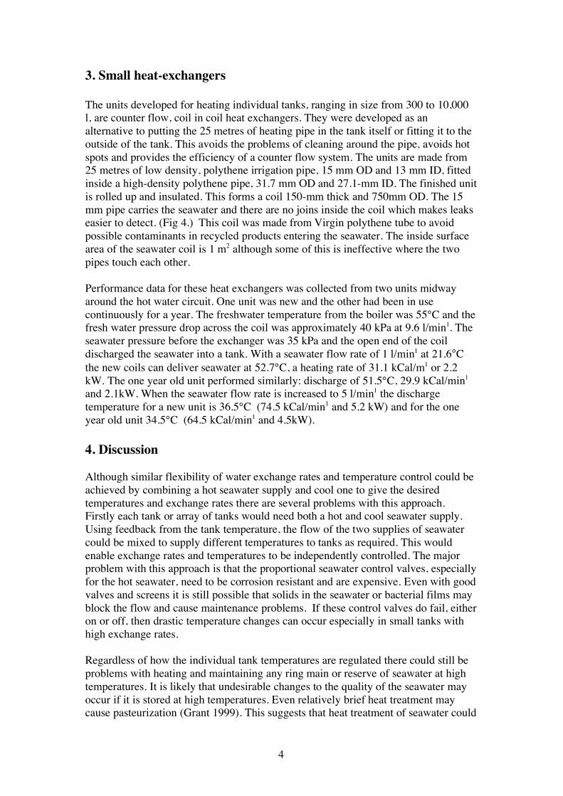
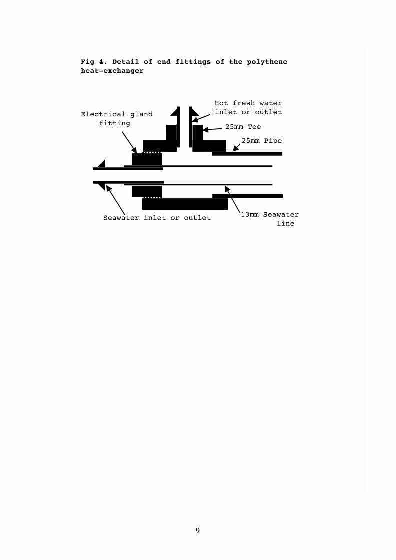
3. Small heat-exchangers The units developed for heating individual tanks, ranging in size from 300 to 10,000 l, are counter flow, coil in coil heat exchangers. They were developed as an alternative to putting the 25 metres of heating pipe in the tank itself or fitting it to the outside of the tank. This avoids the problems of cleaning around the pipe, avoids hot spots and provides the efficiency of a counter flow system. The units are made from 25 metres of low density, polythene irrigation pipe, 15 mm OD and 13 mm ID, fitted inside a high-density polythene pipe, 31.7 mm OD and 27.1-mm ID. The finished unit is rolled up and insulated. This forms a coil 150-mm thick and 750mm OD. The 15 mm pipe carries the seawater and there are no joins inside the coil which makes leaks easier to detect. (Fig 4.) This coil was made from Virgin polythene tube to avoid possible contaminants in recycled products entering the seawater. The inside surface area of the seawater coil is 1 m2 although some of this is ineffective where the two pipes touch each other. Performance data for these heat exchangers was collected from two units midway around the hot water circuit. One unit was new and the other had been in use continuously for a year. The freshwater temperature from the boiler was 55°C and the fresh water pressure drop across the coil was approximately 40 kPa at 9.6 l/min1. The seawater pressure before the exchanger was 35 kPa and the open end of the coil discharged the seawater into a tank. With a seawater flow rate of 1 l/min1 at 21.6°C the new coils can deliver seawater at 52.7°C, a heating rate of 31.1 kCal/m1 or 2.2 kW. The one year old unit performed similarly: discharge of 51.5°C, 29.9 kCal/min1 and 2.1kW. When the seawater flow rate is increased to 5 l/min1 the discharge temperature for a new unit is 36.5°C (74.5 kCal/min1 and 5.2 kW) and for the one year old unit 34.5°C (64.5 kCal/min1 and 4.5kW). 4. Discussion Although similar flexibility of water exchange rates and temperature control could be achieved by combining a hot seawater supply and cool one to give the desired temperatures and exchange rates there are several problems with this approach. Firstly each tank or array of tanks would need both a hot and cool seawater supply. Using feedback from the tank temperature, the flow of the two supplies of seawater could be mixed to supply different temperatures to tanks as required. This would enable exchange rates and temperatures to be independently controlled. The major problem with this approach is that the proportional seawater control valves, especially for the hot seawater, need to be corrosion resistant and are expensive. Even with good valves and screens it is still possible that solids in the seawater or bacterial films may block the flow and cause maintenance problems. If these control valves do fail, either on or off, then drastic temperature changes can occur especially in small tanks with high exchange rates. Regardless of how the individual tank temperatures are regulated there could still be problems with heating and maintaining any ring main or reserve of seawater at high temperatures. It is likely that undesirable changes to the quality of the seawater may occur if it is stored at high temperatures. Even relatively brief heat treatment may cause pasteurization (Grant 1999). This suggests that heat treatment of seawater could
5
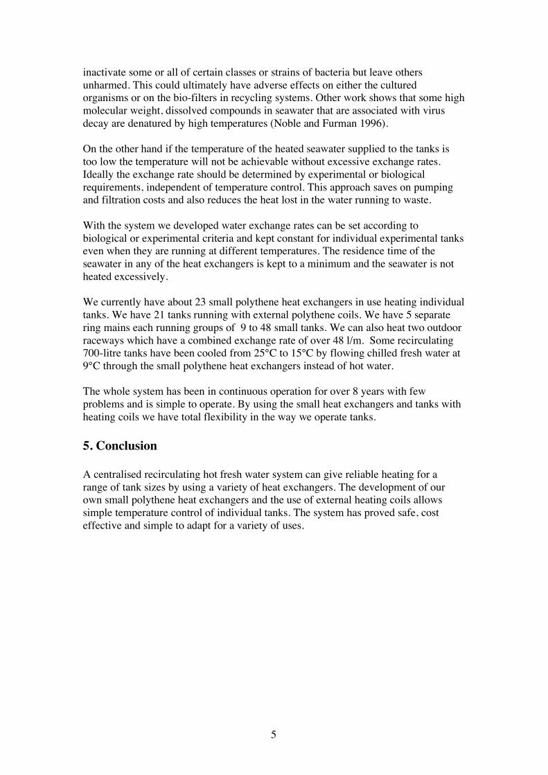
inactivate some or all of certain classes or strains of bacteria but leave others unharmed. This could ultimately have adverse effects on either the cultured organisms or on the bio-filters in recycling systems. Other work shows that some high molecular weight, dissolved compounds in seawater that are associated with virus decay are denatured by high temperatures (Noble and Furman 1996). On the other hand if the temperature of the heated seawater supplied to the tanks is too low the temperature will not be achievable without excessive exchange rates. Ideally the exchange rate should be determined by experimental or biological requirements, independent of temperature control. This approach saves on pumping and filtration costs and also reduces the heat lost in the water running to waste. With the system we developed water exchange rates can be set according to biological or experimental criteria and kept constant for individual experimental tanks even when they are running at different temperatures. The residence time of the seawater in any of the heat exchangers is kept to a minimum and the seawater is not heated excessively. We currently have about 23 small polythene heat exchangers in use heating individual tanks. We have 21 tanks running with external polythene coils. We have 5 separate ring mains each running groups of 9 to 48 small tanks. We can also heat two outdoor raceways which have a combined exchange rate of over 48 l/m. Some recirculating 700-litre tanks have been cooled from 25°C to 15°C by flowing chilled fresh water at 9°C through the small polythene heat exchangers instead of hot water. The whole system has been in continuous operation for over 8 years with few problems and is simple to operate. By using the small heat exchangers and tanks with heating coils we have total flexibility in the way we operate tanks.
5. Conclusion A centralised recirculating hot fresh water system can give reliable heating for a range of tank sizes by using a variety of heat exchangers. The development of our own small polythene heat exchangers and the use of external heating coils allows simple temperature control of individual tanks. The system has proved safe, cost effective and simple to adapt for a variety of uses.
6
Acknowledgments I would like to thank Dr Burke Hill for his support in supporting the funding for the installation of this system. References Huguenin J.E. and Colt J., 1989 Design and Operating guide for Aquaculture seawater systems, Elsevier, Amsterdam. ch 11. 127-134 Ricque, D; Martinez-Vega, JA; Aguirre-Guzman, G., 1993 A low cost recirculating synthetic seawater system for nutritional assays in penaeid shrimp. From Discovery to Commercialization.. European Aquaculture Soc., 1993 p. 161, Special Publication, European Aquaculture Society, no.19 Noble, R.T; Furman JA., 1997 Virus decay and its causes in coastal waters. Applied and Environmental Microbiology, vol 63, no. 1,pp. 77-83, Jan 1997 Grant, IR; Ball, HJ: Rowe, MT., 1999 Effect of higher pasteurization temperatures and longer holding times at 72 degree C, on the inactivation of Mycobacterium paratuberculosis in milk. Letters in Applied Microbiology, vol. 28, no. 6, pp. 461-465, Jun 1999
7
HeatingUnit
HeatingUnit
HeatingUnit
BoilerFreshwater Storage Tank
Supply pump
Pressure release valve
Pump
Hot fresh water supply at 125kPa
Cooled freshwater return at 25kPa
Fig. 1. Circulation of hot fresh water
Seawater SupplyPump
Proportional valve
Temperature sensor
Hot FWSupply
CooledFW
Return
PlateHE
Warm seawater
Tank
WasteSW
Fig. 2 Heating system for tank arrays.
8
Figure. 3 Custom Heat-Exchangers for individual tanks
Electronic control
Tank
Waste SW
Temperaturesensor
Solenoidvalve
Hot freshWater
Cooled FreshWater
PolytheneHeat exchanger
Seawater
PolytheneHeat exchanger
Seawater
Cooled FreshWater
Solenoidvalve
Electronic controlHot freshWater
Waste SW
Tank
Temperaturesensor
Fig 3.1 Heating system for high exchange tanks.
Fig 3.3 Heating system for very low or no exchange tanks.
Fig 3.2 Heating system for low exchange tanks.
Hot freshWater
Electronic control
Cooled FreshWater
Solenoidvalve
Tank
Temperaturesensor
External heatingCoil
9
Hot fresh waterinlet or outlet
25mm Tee
25mm Pipe
13mm Seawaterline
Electrical glandfitting
Seawater inlet or outlet
Fig 4. Detail of end fittings of the polythene heat-exchanger