central tire inflation systems for agricultural...
TRANSCRIPT

Central Tire Inflation Systems
for Agricultural Vehicles
Martin Tigges Managing Partner
PTG Reifendruckregelsysteme GmbH Neuss, Germany
For presentation at the 2015 Agricultural Equipment Technology Conference
Louisville, Kentucky, USA 9-11 February 2015
Published by the American Society of
Agricultural and Biological Engineers 2950 Niles Road, St. Joseph, MI 49085-9659 USA
The Lectures Series has been developed
by the Machinery Systems Committee (MS-47) of ASABE to provide in-depth design resource information for engineers in the agricultural industry.
Topics are related to the power plant, power train, hydraulic system, and chassis components such as operator environment, tires, and electrical equipment for agricultural or
industrial tractors or self-propelled agricultural equipment.
ASABE is grateful to Deere & Company for sponsoring the ASABE Distinguished Lecture Series.

Copyright © 2015 by the American Society of Agricultural and Biological Engineers
All Rights Reserved
Manufactured in the United States of America
This lecture may not be reproduced in whole or in part by any means (with the exception of short quotes for the purpose of review)
without the permission of the publisher. For information, contact:
ASABE, 2950 Niles Rd., St. Joseph, MI 49085-9659 USA. Phone: 269 429 0300 Fax: 269 429 3852 E-mail: [email protected]
ASABE is an educational and scientific organization dedicated to the advancement of engineering applicable to agricultural, food, and biological systems.
For more information visit www.asabe.org.
ASABE Publication Number 913C0115 ASABE Distinguished Lecture Series,
Tractor Design No. 38
The American Society of Agricultural and Biological Engineers is not responsible for statements and opinions advanced in its meetings or printed in its publications. They represent the views of the individual to whom they are credited and
are not binding on the Society as a whole.

ASABE Distinguished Lecture Series No. 38, February 2015 1 © American Society of Agricultural and Biological Engineers
Central Tire Inflation Systems for Agricultural Vehicles Martin Tigges
Managing Partner, PTG Reifendruckregelsysteme GmbH, Neuss, Germany phone: 0049 (0) 2131-52376-0; e-mail: [email protected]
Abstract. This lecture provides an overview of the various benefits of driving with an adjusted tire pressure in the field and on the road. The principle components of PTG’s central tire inflation systems, CTIS, are a dual-line system with seals at nearly zero pressure in the air transmission unit, a main control unit based on a proportional valve system, and various operating panels. Examples of air transmission units for different axle geometries are given as well: the flange-axle solu-tion, the non-driven trailer-axle solution, the bar-axle solution, and the portal-axle solution. Furthermore, the concept of a new sealing method for air transmission units is introduced. A list of PTG’s hydraulic-driven compressors for a sufficient CTIS air supply is given, along with a description of the procedure for calculating the air requirement of each situation. In addition, PTG’s main markets and sales channels are listed. The lecture ends with the outlook for new developments and future market requirements.
Keywords: Central tire inflation systems, CTIS, Tractor tire inflation.

Central Tire Inflation Systems for Agricultural Vehicles
ASABE Distinguished Lecture Series No. 38, February 2015 2 © American Society of Agricultural and Biological Engineers
Introduction Today’s agricultural tractor is a multifunctional farm
machine that has improved rapidly over the last few years to deliver exceptional performance. At a top travel speed of close to 40 mph and easily weighing 55 tons (US) or more with attached equipment, it has developed into an excellent dual-mode vehicle that must: be navigated quickly and safely on the roads to travel
where it is needed, and work the field with maximum tractive efficiency and
with minimum soil compaction. It must also perform these tasks with minimum diesel con-sumption and tire wear.
The connection between the tractor and the road or soil is the tire. Tires transmit the forces from the vehicle to the ground through their contact surfaces. There are vertical forces in the form of weight force and horizontal forces in the form of driving, braking, steering, and tractive forces (with free-rolling wheels). When considering these individ-ual parameters as well as vibrations, slip, vehicle speed, and soil pressure, tire pressure plays an absolutely crucial role.
For road travel and low wear, firm tires are best, but softer, more flexible tires provide better traction in the field and protect the soil. These essentially conflicting require-ments for tractor tires on the road and in the field cannot be met with the same tire pressure. Inflating the tires to a “happy medium,” as previously resorted to in practice, re-sults in unnecessary losses because a medium pressure is too low on the road and definitely too high in the field.
All previous attempts of the tire industry to live up to these expectations with new developments have failed to produce the desired result, although minor improvements were made. Our central tire inflation system or CTIS solves this problem, because it means that tire pressures can be adjusted easily for each situation.
Weight Force The weight force, also called the wheel or axle load,
forms the basis for determining soil impact or soil pressure, expressed as contact area pressure, which is the relation of wheel load to the size of the footprint.
Effectively, the lower the tire pressure, the larger the footprint. Scientists today assume that the average contact area pressure is higher by a factor of 1.25 than the tire pres-sure. In other words, a tire pressure of 9 psi = a soil pres-sure of 11 psi, and a tire pressure of 23 psi = a soil pressure of 29 psi. Therefore, since the soil pressure reduces with decreasing tire pressure, the tire pressure should be kept as low as possible for the purpose of soil protection.
The recommendation, basically, is to use a tire pressure of ≤15 psi in the field. It is imperative, however, to observe the minimum pressure limits stipulated by the tire manufacturer.
Figure 1: NH Tractor with CTIS on the rear axle. Source: PTG.
Figure 2: Contact area pressure with field and road pressure. Source: PTG.

Central Tire Inflation Systems for Agricultural Vehicles
ASABE Distinguished Lecture Series No. 38, February 2015 3 © American Society of Agricultural and Biological Engineers
Figure 3: Depth of track and bulldozing effect. Source: Prof. Volk,
Fachhochschule Soest, Germany.
Rolling Resistance As low tire pressure in the field reduces the contact area
pressure, it also significantly reduces the rut depth or sink-age, especially in the loose soil of a freshly worked field. This in turn notably reduces the soil wedge against which the tire permanently works. This applies particularly to pulled equipment. A rut depth of 0.4 inches corresponds to a constant uphill drive of 1%. A 4-inch rut depth therefore equals a constant uphill drive of 10%.
A shallow rut depth also reduces the leveling effort and may therefore allow working at a lower depth.
Traction and Slip Field work requires a high level of tractive efficiency.
Along with the weight of the tractor, a vital factor here is the shear strength of the soil.
Lowering the tire pressure means that more tire lugs bite into the soil, which improves the shear strength and signifi-cantly increases the drag force. For example, a tire pressure of 23 psi with 15% slip can transmit around 420 daN. Re-ducing the pressure to 11 psi means a transmission of around 600 daN with 15% slip. Ultimately this suggests that by a mere reduction in tire pressure from 23 psi to 11 psi, +40% more traction forces can be transmitted (with constant slip). By implication, this means that a higher tire pressure reduces the tractive efficiency of the tractor.
When using trailers, the required tractive force increases significantly with higher tire pressure, as does the slip. High slip (over 20%), however, damages the soil structure both in tilled fields and on grassland.
Figure 5: Correlation between traction, tire pressure, and slip. Source:
Uppenkamp, Weißbach, and Heitmann, 2009. This relationship between tire pressure and slip is illus-
trated in the following example. A cultivator requires a trac-tive force of around 600 daN. With tire pressure at 23 psi the work is performed with a slip of 22%. If the tire pressure is lowered to 13 psi, the work can be performed with a slip of 16%. This corresponds to a reduction in slip of around 30%.
Lowering the tire pressure also softens the tire on the whole, thereby improving its flex. Increased flexing results in better self-cleaning of the tread. Even on sticky ground, the lugs in the tread no longer clog, meaning that the lugs continue to have proper bite and so ultimately increase the tractive force and reduce the slip.
Travel Speed and Ground Coverage With reduced slip as a result of lower tire pressure, as
described above, the potential ground coverage of the ma-chine increases to the same significant degree.
Slip is the distance traveled in relation to the ideal slip-free path:
0
0
S
SSI −=
Furthermore, the slip can also be calculated using the rate of relative theoretical velocity, V0:
0
0
V
VVI −=
Back to the cultivator example, by adjusting the tire pressure from 22 psi to 13 psi the actual travel speed could be increased from 2.5 mph to 3.1 mph. This ultimately re-sults in time savings of 20%, so work previously requiring 10 hours can now be performed in 8 hours.
Higher Yield Less soil compaction means higher yield. Unfortunately,
it is very hard to find serious academic studies examining this topic. Here, I show you two yield maps of the same corn field in the Midwest US, one from 2010—when no CTIS was in use—and one from 2011 when CTIS was in use on both the tractor and the planter tires. The planter was 36 rows wide and the harvester 12 rows. The 2010 map
Figure 4: Footprint of a typical radial tire. Source: PTG
Central Tire Inflation Systems for Agricultural Vehicles
ASABE Distinguished Lecture Series No. 38, February 2015 4 © American Society of Agricultural and Biological Engineers
shows considerable yield loss in the wheel tracks, while the 2011 map shows very little yield loss in the wheel tracks.
Vibrations A reduction in tire pressure also benefits the driver in
that it increases the spring suspension rate of the tire. It acts like a shock absorber. Using sensors, it has been shown that the vertical acceleration of the driver’s seat (up and down) at different speeds was reduced by more than 50% in une-ven fields. Less vibration not only protects the machine, it also reduces stress and fatigue for the driver.
Road Travel Generally, road travel requires a higher tire pressure.
Higher pressure results in less tire wear, and also less re-sistance thus a reduction in required traction and lower die-sel consumption. These are vital economic arguments for preferring high tire pressure on the road. Higher tire pres-sure also increases road safety because of less tire deflec-tion, which means that the vehicle sways less, especially when cornering. It makes sense to raise the tire pressure up to the maximum indicated in the tire table (unless the ma-jority of travel is empty trips).
This requirement stands in exact contrast with the opti-mum tire pressure when working in the field.
If a high tire pressure is chosen to protect the tires when frequently changing between road travel and field work (e.g. when spreading manure), the effects of it on the field may well be negative. By using larger tires, the tire pres-
sure required for load bearing can be lowered, but the dis-advantages of relatively high wear and rolling resistance and poor road handling remain. Furthermore, the option of using larger tires to enable driving on roads with a lower tire pressure is in many cases severely limited, especially in the case of transport vehicles (e.g. self-loading trailers) because of the limited available space.
Tire Wear Tire pressure that is excessively high or excessively low
results in uneven wear of the tread. About 90% of all tire wear, meaning the abrasion of the tire rubber, happens on the road. Unlike soft, yielding, field soil, a road surface is hard and unyielding, so it is the lug tread of the tractor tire that yields here, with a rubbing effect.
When driving with excessively low tire pressure, the tire can be permanently damaged. Tire wear increases with low tire pressure, for instance when using the aforesaid “happy medium” tire pressure. With low tire pressure, the rolling motion of the tire causes a relative movement, the lug slips across the asphalt and wears out. Simply increasing the tire pressure can reduce tire wear by up to 30%.
Figure 8: Tread wear on the road. Source: PTG.
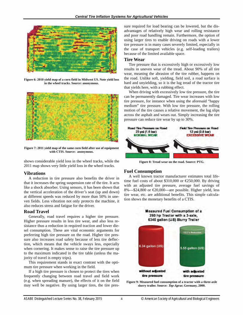
Fuel Consumption A well known tractor manufacturer estimates total life-
time fuel costs of about $310,000 or €250,000. By driving with an adjusted tire pressure, average fuel savings of 8%—$24,800 or €20,000—are possible. Higher yield, less tire wear, etc. are additional benefits. This simple calcula-tion shows the monetary benefits of a CTIS.
Figure 9: Measured fuel consumption of a tractor with a three-axle
slurry trailer. Source: Top Agrar, Germany, 2000.
Figure 6: 2010 yield map of a corn field in Midwest US. Note yield loss in the wheel tracks. Source: anonymous.
Figure 7: 2011 yield map of the same corn field after use of equipment with CTIS. Source: anonymous.

Central Tire Inflation Systems for Agricultural Vehicles
ASABE Distinguished Lecture Series No. 38, February 2015 5 © American Society of Agricultural and Biological Engineers
Technology The solution to setting the right tire pressure in the field
and on the road is a central tire inflation system or CTIS, which enables the driver to adjust tire pressure on the go.
PTG Reifendruckregelsysteme GmbH was founded in 1991 and for almost 25 years now has been engaged exclu-sively in the development, production, and sale of different systems for rapid tire pressure adjustment. Originally starting with CTIS for agricultural purposes, PTG today also success-fully markets semi-automatic systems for trucks and SUVs. We also deliver straight to the factories of almost all Europe-an truck manufacturers, including Paccar (Kenworth).
The development of the CTIS for agricultural vehicles started in 1985 with my thesis. Knowing the advantages of driving with adjusted tire pressure and in the absence of suitable systems, I developed a CTIS for the rear axle of an MF 1014.
Research conducted on the state of the art of air trans-mission units presented solutions used primarily on military vehicles. Different approaches adapted to the various axle geometries were introduced, but all had one thing in com-mon: they were all single-line systems. Single-line systems are constantly pressurized, from the tire to the air transmis-sion unit through to the pressure control valves. Further research led to the realization that these single-line systems were fragile and required significant servicing and mainte-nance, especially the seals in the air transmission units, which had a life of only some 100 operating hours.
Agriculture, however, requires a system that operates re-liably with a minimum of maintenance and that has highly durable seals in the air transmission units. It quickly be-came clear that the life of the seals could be improved sig-nificantly if these were operated largely at zero pressure, in other words, if they were exposed to pressure only when the tire pressure was being changed.
For example, say that a tractor operates around 1,000 hours per year. In a single-line system, the seals in the air transmission units also operate under pressure for 1,000 hours. In a dual-line system, the seals in the air transmis-
sion units are exposed to pressure only when the tire pres-sure is changed, or in this example only about 100 hours. When the tractor reaches 10,000 operating hours, the seals will have worked under pressure for a mere 1,000 hours.
And so the dual-line system was born, where the whole CTIS basically works at zero pressure. It is only exposed to pressure when the tire pressure is changed. Zero pressure in the lines and air transmission units is achieved by using switched wheel valves that are fitted into the rim of each connected wheel. The valve is activated and opened via a second, small, control line. In its basic state, the wheel valve is spring closed and the whole line section following it, including the rotary seal, is depressurized. The wheel valve basically is a non-return valve that can be released. We have used this technology ever since with the best results.
So, what is a dual-line system from PTG, and how is it designed? Aside from the wheel valve it basically consists of the following three components: a main control unit under the vehicle, an operating panel in the driver’s cab, and an air transmission unit for each connected wheel.
Main Control Unit The main problem in the control is to determine the ac-
tual pressure in the tire. The control process produces vari-ous dynamic conditions in the lines, with air at times flow-ing at high speeds. The pressure in the lines is quite differ-ent from the current static pressure in the tire. The CTIS, however, only offers the option to measure the pressure in the lines, not in the tire. This means we know only the dy-namic pressure, which is quite different from the actual pressure. The problem could be resolved by interrupting the control process systematically a number of times in order to determine the actual pressure. This approach, however, prolongs the actual control process and therefore, in our view, is not an option.
Thirty years ago, we went a different way. The heart of our control unit to this day is a proportional valve. At the start of the control process, i.e., when the difference be-tween target and actual pressure is highest, the cross sec-tions in the proportional valve are fully opened. This en-sures maximum air passage of approximately 2,500 l/min.
Figure 10: Wheel valve. Source: PTG.
Figure 11: Performance characteristic of a proportional valve during deflation. Source: PTG.

Central Tire Inflation Systems for Agricultural Vehicles
ASABE Distinguished Lecture Series No. 38, February 2015 6 © American Society of Agricultural and Biological Engineers
The smaller the difference between target and actual pres-sure, the smaller the cross sections need to be in the valve. The proportional valve is able to adjust the actual pressure to the target pressure with an accuracy of ± 0.05 bar. Other CTIS generally struggle to achieve such accuracy.
The main control unit is normally supplied with air from the brake system and besides the proportional valve today it supplies air to other valves, including the pressure reducer and quick release valve.
We have used the proportional valve system for several decades now. It is absolutely reliable and hard to beat in terms of control accuracy. It forms the basis of our control units to this day.
Analog Operating Panel When we started with the CTIS, we used analog oper-
ating panels. The driver used a pressure dial to preset the new target pressure on the target pressure gage and then start the CTIS with a green button. Then the wheel valves were opened and the adjustment started. Once the target pressure was reached, the wheel valves were closed and all lines bled.
This version of operat-ing panel was technically simple and inexpensive. But it meant that the driver had to preset a new target pressure for every control process, which—particul-arly when many processes were required—was con-sidered quite a nuisance.
Digital Operating Panel Around 10 years ago, we therefore developed the digital
operating panel. Layout and functionality were worked on in a student research project, in the course of which numer-ous practitioners were consulted. The resulting operating panel can be operated almost intuitively and requires little explanation. This operating panel can control up to three control circuits simultaneously, for example the tires on the tractor’s front axle, the tires on the tractor’s rear axle, and the tires on the trailer, planter, etc.
Using the SET button, the operator can store separate road and field inflation pressures for each control circuit. The control circuits are selected using the three buttons at the center of the panel. Activated control circuits are indicated by the small LED lighting up the button. The two buttons on the left of the panel are used to access the preset road and field target pressures for all activated control circuits.
The plus and minus buttons on the right are used to overwrite the preset target pressures in increments of 1.5 psi, or 0.1 bar. If, for instance, the driver comes across a
very wet furrow or soft spot in the field, he may temporari-ly need to lower the tire pressure even more. The on/off switch is on the underside of the operating panel, along with a button for the brightness control of the display be-cause at night the display may be too bright for the driver.
The user interface on the JD-CommandCenter is largely based on the operating concept of that digital control unit. It similarly allows selection of control circuits, accessing of preset road and field pressures, and overriding of the target pressures.
ISOBUS-Based Control Unit Our latest development is an ISOBUS-based control unit.
The ISOBUS control unit allows us to control the propor-tional valve using the tractor’s on-board terminal. The user interface on the JD-CommandCenter is largely based on the operating concept of the digital control unit. It similarly al-lows selection of control circuits, accessing of preset road and field pressures and overriding of the target pressures.
The control unit has now been tested by John Deere Germany and approved in a first step for the 6R model.
Figure 12: Analog operating
panel. Source: PTG.
Figure 13: Digital operating panel. Source: PTG.
Figure 14: JD terminal showing PTG control page. Source: PTG.

Central Tire Inflation Systems for Agricultural Vehicles
ASABE Distinguished Lecture Series No. 38, February 2015 7 © American Society of Agricultural and Biological Engineers
Air Transmission Units A rotary union of an air transmission unit always con-
sists of two parts: the rotor (the spinning part) and the stator (the static part). Integrated into the stator are special seals that are resistant to compression. Normally, these seals form annular channels where the air transmission takes place. Optimizing the diameter of the annular channels on the air transmission volume is always a challenge. In most cases the given space at the axle is the determining factor. Furthermore, the diameter of seals should be as small as possible. By this we minimize the circumferential speed they have to withstand, and a low circumferential speed means a longer operating life.
The seals get a lifetime grease filling before they are mounted. It is a very special grease and repeated greasing is not necessary, so PTG air transmission units are mainte-nance free. In the dual line system these seals reach a re-markable operating life, normally up to 10,000 operating hours without any problems.
As each type of axle requires an individual design of the air transmission unit, PTG offers many different models. Below are the most important ones and their installation.
Bar-Axle Solution (RDS/Radial) For bar axles we offer an air transmission unit with a de-
sign based on my thesis. It is placed on the bar axle. The required space on both sides is only 100 mm between the axle housing and the axle wheel clamp.
The stator of the air transmission unit for a bar axle is screwed on the trumpet house (four screws, minimum M6, Figure 16). To ensure an accurate centric installation we offer a drilling plate and a depth stop (Figure 18). The rotor is fixed by a clamp ring on the drive shaft (Figure 19). This air transmission unit is proven and accepted, e.g. by John Deere.
Figure 16: Air transmission unit for bar axles. Source: PTG.
Figure 17: Air transmission unit for a bar axle. Source: PTG.
Figure 18: Drilling template. Source: PTG.
Figure 15: Dual-line air transmission unit for a bar axle including wheel valve. Source: PTG.

Central Tire Inflation Systems for Agricultural Vehicles
ASABE Distinguished Lecture Series No. 38, February 2015 8 © American Society of Agricultural and Biological Engineers
Flange-Axle Solution (AIRBOX/drive 2L)
It is not possible to adapt the bar-axle solution to flange axles or to steered front axles because the diameter of the transmission unit would be too big. So for this type of axle we offer a small air transmission unit that is installed on the
outer side of the wheel. The brackets for these units are fixed by wheel bolts. The control and air feed lines go above the mudguard through a telescopic tube. They can be easily disconnected at the air transmission unit if the CTIS is not needed. The tube ends can be fixed by using the park-couplings on the mudguard (Figure 21). In this posi-tion we have no overlap of CTIS parts.
Non-driven Trailer-Axle Solution (RDS/GW) Technically it is not a problem to have centric drilling
through a non-driven axle. Most of the axle manufacturers in Europe offer their axles with a drilling according to our requirements. For safety and liability reasons, only the manufacturer is allowed to do the drilling.
The drilling itself is used as an air channel. There are screw threads on both sides of the channel. On the wheel side we screw in the air transmission unit and on the other end we use a special screw connection. To implement the dual line system we place the control line in the drilling as well. The trick is the special screw connection (Figure 23). It allows us to bring the control line into the air feed line without losing any pressure. To protect the axle bearing against water, mud, and dust we use a two-lip seal. The seal itself is protected by a special cover. Without this cover it would be very easy to bring water into the axle bearing, for instance with a pressure washer. This way of sealing meets the requirements of all European axle manufacturers.
Figure 22: Air transmission unit for a non-driven trailer axle.
Source: PTG.
Figure 23: Special screw connection. Source: PTG.
Figure 19: Clamp ring. Source: PTG.
Figure 20: JD Tractor equipped with CTIS on front and rear axles. Source: PTG.
Figure 21: Park-couplings. Source: PTG.

Central Tire Inflation Systems for Agricultural Vehicles
ASABE Distinguished Lecture Series No. 38, February 2015 9 © American Society of Agricultural and Biological Engineers
Portal-Axle Solution (RDS/Portal) Self-propelled harvesters are very often equipped with
portal axles. The drive shaft can easily be drilled as well, but a cross-hole like we use for the trailer axles is not pos-sible. Both solutions are similar. On the wheel side end we install the special screw connection and on the other end we put the air transmission unit, so the air transmission unit is
placed inside the axle tube. It is well protected at this spot but hard to reach, so it is a big advantage that our air trans-mission units are reliable and maintenance free. All corn harvesters manufactured by New Holland, CNH Group, have drilled portal axles now so that the PTG system can easily be installed or retrofitted.
Figure 24: Air transmission unit for non-driven trailer axles. Source: PTG.
Figure 25: Air transmission unit for a portal axle. Source: PTG.

Central Tire Inflation Systems for Agricultural Vehicles
ASABE Distinguished Lecture Series No. 38, February 2015 10 © American Society of Agricultural and Biological Engineers
Figure 26: Self-propelled harvester equipped with CTIS on the front
axle. Source: PTG.
New Concept Solution for Flange and Bar Axles (RDS/Axial)
As installation space is limited it is difficult to integrate an air transmission unit into the front axle of a tractor. So, we have developed a new concept for an air transmission unit. The new idea is that the seals are radially stacked, so we need less width of installation space for the air trans-mission unit and we have more options for integrating it.
In the basic state the seals are placed in recessed channels and have no contact with the counter-running surface. This means no seal wear and less rolling resistance. When the CTIS has been activated the seals are blown forwards axially against the counter-running surface. Thus they form annular channels where the air transmission can take place. When the adjustment procedure is finished the complete unit is depres-surized again and the seals slip back into their channels. (This is comparable to the concept of a disc brake.)
In the following photos you can see this concept installed at the front and rear axle of a tractor. In this case the wheel
flange is also the rotor of our air transmission unit. This new air transmission unit has been successfully
tested by test laboratories. Of course, this is not a retrofit solution. This concept can only be realized in co-operation with a tractor axle manufacturer.
Figure 27: New air transmission unit for flange axles, without wheel.
Source: PTG.
Figure 28: New air transmission unit for flange axles, with wheel.
Source: PTG.
Figure 29: Drawing of new air transmission unit for flange axle. Source: PTG.

Central Tire Inflation Systems for Agricultural Vehicles
ASABE Distinguished Lecture Series No. 38, February 2015 11 © American Society of Agricultural and Biological Engineers
Additional Air Supply and Compressors
In Germany we have the big advantage that all agricul-tural trailers with an overall weight above 3.5 t must have a pneumatic air brake system. Because of that fact all tractors in Germany are already equipped with an on-board com-pressor. We can use it for inflating the tires. By installing a safety valve we ensure a sufficient air supply for the air brake system at any time. The safety valve opens at 94 psi (6.5 bar), and the maximum operating pressure is 123 psi (8.5 bar). A standard on-board compressor delivers about 7.7 cfm (220 l/min) (nominal rotation speed). In our fol-lowing example we need a total of 102 cf (2,880 l) of air to increase the pressure in all four tractor tires from 12 psi (0.8 bar) to 23 psi (1.6 bar). The standard on-board com-pressor needs approximately 13 min. to deliver the required volume.
In most other countries agricultural trailers are not re-quired to have a pneumatic air brake system, so tractors are normally not factory equipped with an on-board compres-sor. So there is a need for us to offer additional compressors to our customers, either to inflate the tires at all or to achieve acceptable inflation times. Just think of a tractor with a three-axle slurry tanker-trailer: The air requirement for inflating all 10 tires up to road pressure can easily reach a volume of 645 cf (17,000 l) and even more. A standard on-board compressor would be overstrained by this.
For agricultural vehicles PTG offers hydraulic-driven piston compressors with three different capacities: K500: two-cylinder piston compressor, air-cooled, real
output of 21 cfm or 600 l/min (29 psi or 2 bar counter pressure), oil requirement of 0.9 cfm or 25 l/min;
Figure 30: PTG compressor K500. Source: PTG.
K1000: two-cylinder piston compressor, fan-cooled, real output of 42 cfm or 1,200 l/min (29 psi or 2 bar counter pressure), oil requirement of 1.6 cfm or 45 l/min;
Figure 31: PTG compressor K1000. Source: PTG.
K3000: four-cylinder piston compressor, air-cooled,
real output of 113 cfm or 3,200 l/min (29 psi or 2 bar counter pressure), oil requirement of 2.8 cfm or 80 l/min.
Figure 32: PTG compressor K3000. Source: PTG.
PTG prefers piston compressors to rotary screw com-
pressors because they are much more convenient for inter-mittent operation. Rotary screw compressors are designed

Central Tire Inflation Systems for Agricultural Vehicles
ASABE Distinguished Lecture Series No. 38, February 2015 12 © American Society of Agricultural and Biological Engineers
for continuous operation, and permanent switching opera-tions (on/off) shorten their design life because if the duty cycle is too short, condensate occurs in the oil circuit caus-ing higher wear. Piston compressors also require much less maintenance, only an annual oil change and air filter con-trol. In contrast, rotary screw compressors also need per-manent monitoring of the various control valves (intake control valve, oil thermostat, relief valve, etc.) and the oil cooler has to be checked regularly.
All our hydraulic-driven compressors have the same mechanism. While inflating the tires the pressure in the additional air reservoir falls. When it reaches a pressure of 55 psi (3.8 bar) a two-point pressure switch opens a hy-draulic solenoid valve. Now the oil flow is powering the compressor. As soon as all tires have reached their road pressure the pressure in the additional air reservoir goes up again. At 113 psi (7.8 bar) the hydraulic solenoid valve is shut off by the two-point pressure switch and the compres-sor stops.
Figure 33: Electropneumatic and wiring schematic for compressor K1000. Source: PTG.
To give our customers support in choosing the right
compressor we calculate their air requirement. In the first step we calculate the air requirement. We know the theoret-ical volume of most agricultural tires; many tire manufac-turer provide this data in their tire handbooks as well. The theoretical volume is multiplied by delta p and the number of tires. In the second step all calculated volumes of the different tires are added. The result is the total air require-ment. In the given example it is 645 cf (17,218 l). So we need this volume to inflate all 10 tires up to road level. Our four-cylinder piston compressor K3000 needs 6 min. and the two-cylinder piston compressor K1000 needs 17 min. to deliver this volume.
Market Penetration and Future Prospects
In 2014 PTG sold nearly 450 CTIS for agricultural vehi-cles worldwide. Our core markets are Germany and the Netherlands. There is an increasing but low demand from Eastern European countries. CTIS is still nearly unknown in Scandinavia and our neighboring countries France and Great Britain. The reasons for the low demand there are the lower average farm size and surely the fact that tractors there normally do not have an on-board compressor.
In 2012 we started a co-operation with Precision Infla-tion LLC, which markets and sells our products in the US and Canada. Sales figures are still restrained but the feed-back of our customers is very good. This makes us very optimistic for the future. I am sure that the market potential of our CTIS in North America is very high.
Figure 34: Air requirement calculation. Source: PTG.

Central Tire Inflation Systems for Agricultural Vehicles
ASABE Distinguished Lecture Series No. 38, February 2015 13 © American Society of Agricultural and Biological Engineers
Looking on the different types of agricultural vehicles we see different stages of development. For big slurry trail-ers and manure spreaders a CTIS is nearly indispensable. Accordingly, the demand is high and most manufacturers are offering a CTIS as an ex-factory option. We deliver our systems to nearly all well known manufacturers in Europe. It is important to note that the slurry trailer industry in Eu-rope is fragmented; even the bigger players are too small to develop their own CTIS.
The tractor market is much behind in using CTIS, as to-day the market pressure isn’t high enough to force tractor manufacturers to offer CTIS factory installed. As a result, nearly all tractor CTIS are still retrofit solutions. But times are changing. AGCO/Fendt, market leader in Germany, has started to promote their own CTIS for the 800 and 900 se-ries. It is fully integrated and based on our dual line tech-nique. Even though we gave a lot of support for this devel-opment it has been launched as a 100% AGCO system. A second manufacturer has started to copy our retrofit solution, the AIRBOX/drive 2L. We feel honored.
In co-operation with John Deere Germany we have as-sembled a special dealer kit for the JD 6R series. From our point of view the air transmission units on the rear axle and the ISOBUS-based control unit have the quality of a facto-ry option. This kit has official approval by John Deere.
An upcoming market for CTIS is the forage harvester industry. In co-operation with New Holland, part of the CNH Group, we developed a fully integrated CTIS. Only little modifications to the design of the front axles (centric drilling) were necessary to adopt our solution.
I am sure that in the meantime every tractor manufactur-er has established a task force working on solutions for a fully integrated CTIS. Within the next 5 to 10 years I ex-pect that all well known tractor manufacturers will offer a CTIS for their vehicles, at least as an option. For the 200+ horsepower class a CTIS will be part of the standard equipment. For forage harvesters and planters I predict a similar development.
The tire industry monitors the increasing demand of CTIS very closely. Up to now, they have tried to develop new tires that are smooth on the soil and safe on the road
with a constant tire pressure. With a CTIS they have many more options. I won’t be surprised if a new tire especially designed for a CTIS will be presented within the next 3 to 4 years. This will stimulate the demand of CTIS as well.
Today, it is still the responsibility of the driver to adjust the right, optimal tire pressure for each new driving situa-tion. But this is asking too much of the driver. Of course he is able to switch between standard field and road pressures. But he can’t know all optimal pressure stages for each tire dimension with different wheel loads, speeds, and deflec-tions. So for the future we need fully automatic tire infla-tion systems, instead of expecting the driver to do this. Of course, we need a lot of extra sensor technology. Scientists are already working on these challenges. Nevertheless, I assume that it will take another 8 to 10 years until we see the first prototypes of a fully automatic tire inflation sys-tem.
References Haag, C. (2004): Konzeption und Entwicklung einer universell
einsetzbaren Bedienund Regeleinheit für Reifendruckregelsys-teme. Diplomarbeit vorgelegt an der Fachhochschule Köln, In-stitut für Landmaschinentechnik und Regenerative Energien.
Michelin Reifenwerke AG & Co. KGaA, Abteilung Land-wirtschaftsreifen Fachliche Beratung: Prof. Dr. Ludwig Volk, FH Südwestfalen, Soest (2012): Das Bodenbuch.
Theißen, G. (2004): Weniger Bodendruck und mehr Zugkraft. In: profi 2004, H.9, S. 66-68.
Uppenkamp, N., Weißbach,M., Heitmann,G. (2009): Reifen richtig wählen und einsetzen. DLG-Merkblatt 356, Frankfurt am Main: DLG-Verlag.
Volk, L.(2009): Traktor, Kapitel IV. FH Südwestfalen: Veröffen-tlichtes Vorlesungsskript, Internet 1.12.2009: http:// www3.fh-swf.de/fbaw/volk/download/Traktor2009_IV.pdf.
Wettmann, P. (2010): Betriebsindividuelle Rentabilitätsunter-suchungen von angepasstem Reifendruck und Ballastierung bei Traktoren — basierend auf praktischen Untersuchungen zur Wechselwirkung Fahrwerk / Boden. Diplomarbeit vorgelegt an der Hochschule Weihenstephan-Triesdorf, Fakultät für Landwirtschaft.

1518 TRANSACTIONS OF THE ASABE