centrifugal fans rdh belt driven august 2013
TRANSCRIPT
1
Centrifugal Fans RDH belt driven
Issue 2.5 EN August 2013
I
AMCA
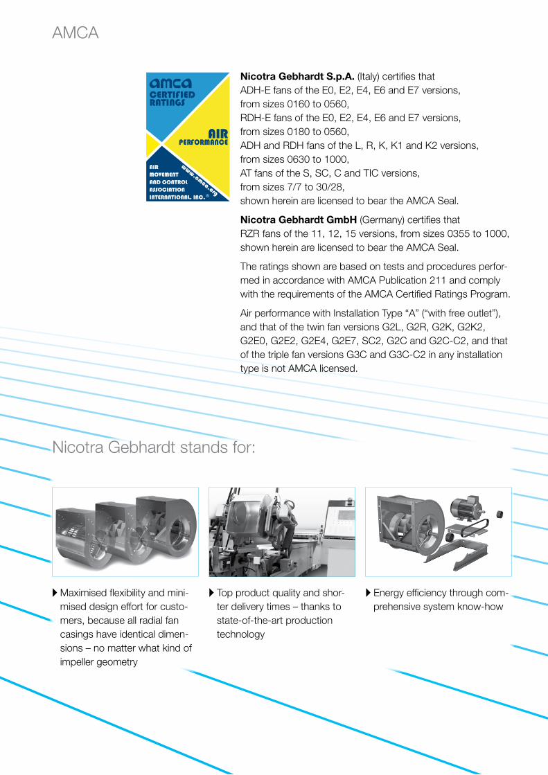
A Maximised flexibility and mini-mised design effort for custo-mers, because all radial fan casings have identical dimen-sions – no matter what kind of impeller geometry
Nicotra Gebhardt stands for:
A Top product quality and shor-ter delivery times – thanks to state-of-the-art production technology
A Energy efficiency through com-prehensive system know-how
Nicotra Gebhardt S.p.A. (Italy) certifies that ADH-E fans of the E0, E2, E4, E6 and E7 versions, from sizes 0160 to 0560, RDH-E fans of the E0, E2, E4, E6 and E7 versions, from sizes 0180 to 0560, ADH and RDH fans of the L, R, K, K1 and K2 versions, from sizes 0630 to 1000, AT fans of the S, SC, C and TIC versions, from sizes 7/7 to 30/28, shown herein are licensed to bear the AMCA Seal.
Nicotra Gebhardt GmbH (Germany) certifies that RZR fans of the 11, 12, 15 versions, from sizes 0355 to 1000, shown herein are licensed to bear the AMCA Seal.
The ratings shown are based on tests and procedures perfor-med in accordance with AMCA Publication 211 and comply with the requirements of the AMCA Certified Ratings Program.
Air performance with Installation Type “A” (“with free outlet”), and that of the twin fan versions G2L, G2R, G2K, G2K2, G2E0, G2E2, G2E4, G2E7, SC2, G2C and G2C-C2, and that of the triple fan versions G3C and G3C-C2 in any installation type is not AMCA licensed.
II
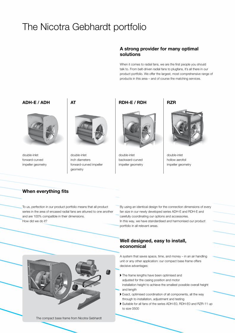
ADH-E / ADH AT RDH-E / RDH RZR
A strong provider for many optimal solutions
When it comes to radial fans, we are the first people you should
talk to. From belt-driven radial fans to plugfans, it’s all there in our
product portfolio. We offer the largest, most comprehensive range of
products in this area – and of course the matching services.
The Nicotra Gebhardt portfolio
Well designed, easy to install, economical
A system that saves space, time, and money – in an air handling
unit or any other application: our compact base frame offers
decisive advantages:
A The frame lengths have been optimised and
adjusted for the casing position and motor
installation height to achieve the smallest possible overall height
and length
A Exact, optimised coordination of all components, all the way
through to installation, adjustment and testing
A Suitable for all fans of the series ADH-E0, RDH-E0 and RZR-11 up
to size 0500
The compact base frame from Nicotra Gebhardt
double-inlet
forward-curved
impeller geometry
double-inlet
inch diameters
forward-curved impeller
geometry
double-inlet
backward-curved
impeller geometry
double-inlet
hollow aerofoil
impeller geometry
When everything fits
To us, perfection in our product portfolio means that all product
series in the area of encased radial fans are attuned to one another
and are 100% compatible in their dimensions.
How did we do it?
By using an identical design for the connection dimensions of every
fan size in our newly developed series ADH-E and RDH-E and
carefully coordinating our options and accessories.
In this way, we have standardised and harmonised our product
portfolio in all relevant areas.

2
proSELECTA II
proSELECTA II is a technical selection program that allows you to
configure your own individually designed fan. It provides you with
the opportunity to choose from the entire range of fan types and
their associated options.
Simple and reliable selection
The result from proSELECTA II is the provision of all the
technical data for your fan, including sound level data, dimension
specifications and accessories. Apart from that, as a registered
user, your purchase prices are provided. Additionally fully
dimensioned drawings in DXF format are available, which can be
downloaded and transferred straight into your CAD system.
So that you can be sure
Models and options that are technically not permissible, are
automatically excluded in proSELECTA II. So there is no chance
that you will configure a “wrong” device option.
What else is important to you
During the fan selection process, you can choose any of the
standardised ATEX options.
Free registration and many advantages
You can register as a proSELECTA II user with us, which enables us
to offer you faster order processing. What this means for you is:
A The complete configuration of your fan with its associated system
accessories and belt drive layout.
A The possibility to produce fans that operate via a frequency
inverter.
A The option of saving your own fan configuration on our server.
A The opportunity to modify your saved configuration, even over the
phone to your Nicotra Gebhardt representative.
3
ADH
ATRD
HRZ
RAc
cess
orie
sDe
scrip
tion
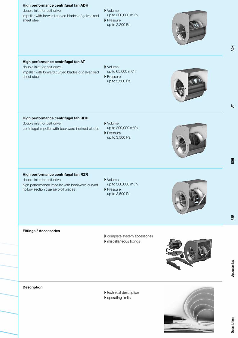
Description A technical descriptionA operating limits
Fittings / Accessories A complete system accessoriesA miscellaneous fittings
High performance centrifugal fan RZRdouble inlet for belt drive high performance impeller with backward curved hollow section true aerofoil blades
High performance centrifugal fan RDHdouble inlet for belt drive centrifugal impeller with backward inclined blades
High performance centrifugal fan ADHdouble inlet for belt drive impeller with forward curved blades of galvanised sheet steel
A Volume
up to 300,000 m³/hA Pressure
up to 3,500 Pa
A Volume
up to 290,000 m³/hA Pressure
up to 3,500 Pa
A Volume
up to 300,000 m³/hA Pressure
up to 2,200 Pa
High performance centrifugal fan ATdouble inlet for belt drive impeller with forward curved blades of galvanised sheet steel
A Volume
up to 65,000 m³/hA Pressure
up to 2,500 Pa
4
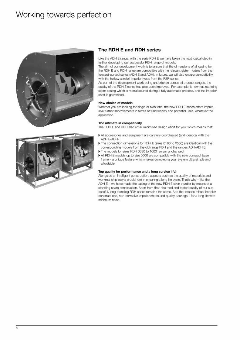
The RDH E and RDH series
Like the ADH E range, with the serie RDH E we have taken the next logical step in further developing our successful RDH range of models. The aim of our development work is to ensure that the dimensions of all casing for the RDH E and RDH range are compatible with the relevant sister models from the forward-curved series (ADH E and ADH). In future, we will also ensure compatibility with the hollow aerofoil impeller types from the RZR series. As part of the development work being undertaken across all product ranges, the quality of the RDH E series has also been improved. For example, it now has standing seam casing which is manufactured during a fully automatic process, and the impeller shaft is galvanised.
New choice of modelsWhether you are looking for single or twin fans, the new RDH E series offers impres-sive further improvements in terms of functionality and potential uses, whatever the application.
The ultimate in compatibilityThe RDH E and RDH also entail minimised design effort for you, which means that:
A All accessories and equipment are carefully coordinated (and identical with the ADH E/ADH).
A The connection dimensions for RDH E (sizes 0180 to 0560) are identical with the corresponding models from the old range RDH and the ranges ADH/ADH E.
A The models for sizes RDH 0630 to 1000 remain unchanged.A All RDH E models up to size 0500 are compatible with the new compact base
frame – a unique feature which makes completing your system ultra simple and affordable!
Top quality for performance and a long service life!Alongside an intelligent construction, aspects such as the quality of materials and workmanship play a crucial role in ensuring a long life cycle. That’s why – like the ADH E – we have made the casing of the new RDH E even sturdier by means of a standing seam construction. Apart from that, the tried and tested quality of our suc-cessful, long-standing RDH series remains the same. And that means robust impeller constructions, non-corrosive impeller shafts and quality bearings – for a long life with minimum noise.
Working towards perfection
5
RDH E0
RDH E2 / RDH R
RDH E4 / RDH K
RDH E6 / RDH K1
RDH E7 / RDH K2
RDH G2E4 / RDH G2K
RDH G2E7 / RDH G2K2
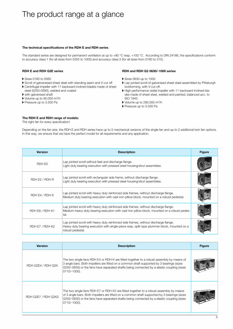
The technical specifications of the RDH E and RDH series.
The standard series are designed for permanent ventilation at up to +80 °C resp. +100 °C. According to DIN 24166, the specifications conform to accuracy class 1 (for all sizes from 0355 to 1000) and accuracy class 2 (for all sizes from 0180 to 315).
RDH E and RDH G2E series
A Sizes 0180 to 0560A Scroll of galvanesed sheet steel with standing seam and V-cut offA Centrifugal impeller with 11 backward inclined blades made of sheet
steel (0250-0560), welded and coatedA with galvanised shaftA Volume up to 90.000 m3/hA Pressure up to 3.500 Pa
RDH and RDH G2-0630/-1000 series
A Sizes 0630 up to 1000A Lap jointed scroll of galvanised sheet steel assembled by Pittsburgh
lockforming, with V-cut off.A High performance radial impeller with 11 backward inclined bla-
des made of sheet steel, welded and painted, balanced acc. to ISO 1940.
A Volume up to 290.000 m3/hA Pressure up to 3.500 Pa
The RDH E and RDH range of models: The right fan for every specification!
Depending on the fan size, the RDH E and RDH series have up to 5 mechanical versions of the single fan and up to 2 additional twin fan options. In this way, we ensure that we have the perfect model for all requirements and any application.
Lap jointed scroll without feet and discharge flange. Light duty bearing execution with pressed steel housing/strut assemblies.
Version
Version
Figure
Figure
Description
Description
Lap jointed scroll with rectangular side frame, without discharge flange. Light duty bearing execution with pressed steel housing/strut assemblies.
Lap jointed scroll with heavy duty reinforced side frames, without discharge flange. Medium duty bearing execution with cast iron pillow block, mounted on a robust pedestal.
The two single fans RDH E4 or RDH K are fitted together to a robust assembly by means of 3 angle bars. Both impellers are fitted on a common shaft supported by 3 bearings (sizes 0250/-0630) or the fans have separated shafts being connected by a elastic coupling (sizes 0710/-1000).
Lap jointed scroll with heavy duty reinforced side frames, without discharge flange. Medium-heavy duty bearing execution with cast iron pillow block, mounted on a robust pedes-tal.
The two single fans RDH E7 or RDH K2 are fitted together to a robust assembly by means of 3 angle bars. Both impellers are fitted on a common shaft supported by 3 bearings (sizes 0250/-0630) or the fans have separated shafts being connected by a elastic coupling (sizes 0710/-1000).
Lap jointed scroll with heavy duty reinforced side frames, without discharge flange. Heavy duty bearing execution with single-piece resp. split-type plummer block, mounted on a robust pedestal.
The product range at a glance
6
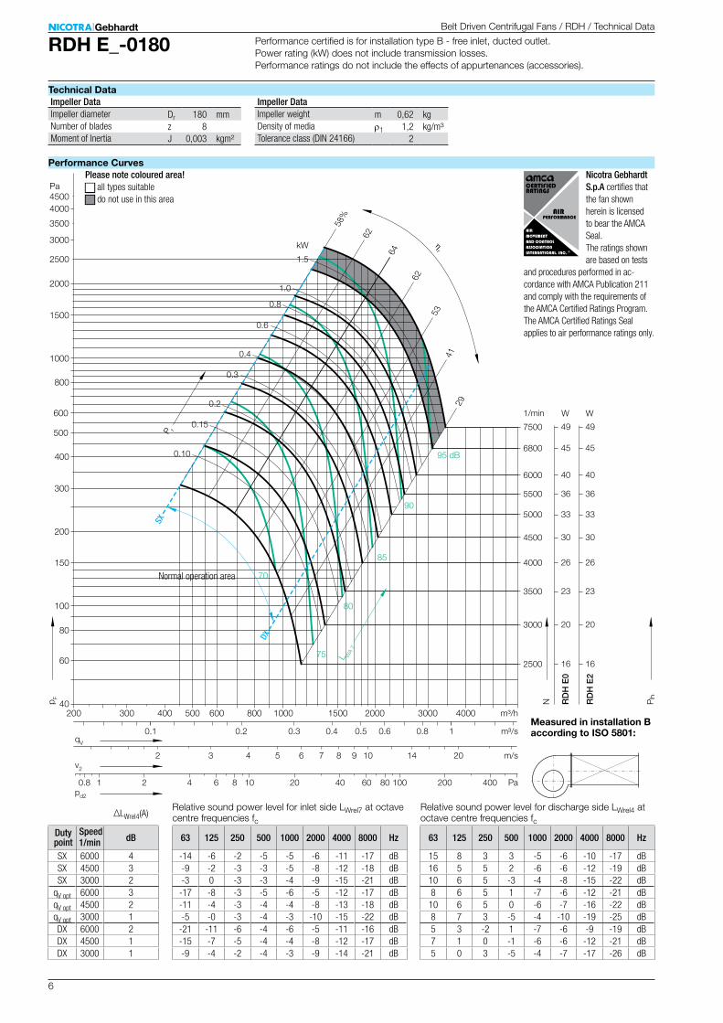
RDH E_-0180
Dr 180 mmz 8J 0,003 kgm²
m 0,62 kgr1 1,2 kg/m³
2
33
16
20
40
23
5000
2500
3000
6000
3500
RD
H E
0
RD
H E
2
W W
100
150
200
300
400
500
600
800
1000
1500
2000
2500
3000
3500
4000
Pa
60
80
4500
1/min
264000
304500
365500
456800
497500
33
16
20
40
23
26
30
36
45
49
m/s
Pa
m³/h
m³/s
40
3 4 5 6 7 8 9 10 14 20
4 6 8 10 20 40 80 100 200 400
1
60
40003000
0.8
2000
0.6
1500
0.50.3 0.4
1000
53
2941
62
64
62
58%
85
90
70
80
75
500 600 800
0.2
95 dB
kW
1.0
0.8
1.5
0.10
0.15
0.4
0.2
0.3
400
0.6
300200
0.1
2
0.8 1 2
ηr
v2
qV
pd2
p F
N Pb
P r
L WA
7
SX
DX
∆LWrel4(A)
63 125 250 500 1000 2000 4000 8000 Hz
-14 -6 -2 -5 -5 -6 -11 -17 dB-9 -2 -3 -3 -5 -8 -12 -18 dB-3 0 -3 -3 -4 -9 -15 -21 dB-17 -8 -3 -5 -6 -5 -12 -17 dB-11 -4 -3 -4 -4 -8 -13 -18 dB-5 -0 -3 -4 -3 -10 -15 -22 dB
-21 -11 -6 -4 -6 -5 -11 -16 dB-15 -7 -5 -4 -4 -8 -12 -17 dB-9 -4 -2 -4 -3 -9 -14 -21 dB
63 125 250 500 1000 2000 4000 8000 Hz
15 8 3 3 -5 -6 -10 -17 dB16 5 5 2 -6 -6 -12 -19 dB10 6 5 -3 -4 -8 -15 -22 dB8 6 5 1 -7 -6 -12 -21 dB10 6 5 0 -6 -7 -16 -22 dB8 7 3 -5 -4 -10 -19 -25 dB5 3 -2 1 -7 -6 -9 -19 dB7 1 0 -1 -6 -6 -12 -21 dB5 0 3 -5 -4 -7 -17 -26 dB
1/min dB
SX 6000 4SX 4500 3SX 3000 2
qV opt 6000 3qV opt 4500 2qV opt 3000 1DX 6000 2DX 4500 1DX 3000 1
Belt Driven Centrifugal Fans / RDH / Technical Data
Technical Data
Performance Curves
Relative sound power level for inlet side LWrel7 at octave centre frequencies fc
Relative sound power level for discharge side LWrel4 at octave centre frequencies fc
Measured in installation B according to ISO 5801:
Impeller Data Impeller DataImpeller diameterNumber of bladesMoment of Inertia
Impeller weightDensity of mediaTolerance class (DIN 24166)
Please note coloured area!N all types suitableN do not use in this area
Performance certified is for installation type B - free inlet, ducted outlet. Power rating (kW) does not include transmission losses. Performance ratings do not include the effects of appurtenances (accessories).
Speed Duty point
Normal operation area
Nicotra Gebhardt S.p.A certifies that the fan shown herein is licensed to bear the AMCA Seal. The ratings shown are based on tests
and procedures per formed in ac-cordance with AMCA Publication 211 and comply with the requirements of the AMCA Certified Ratings Program. The AMCA Certified Ratings Seal applies to air performance ratings only.
7
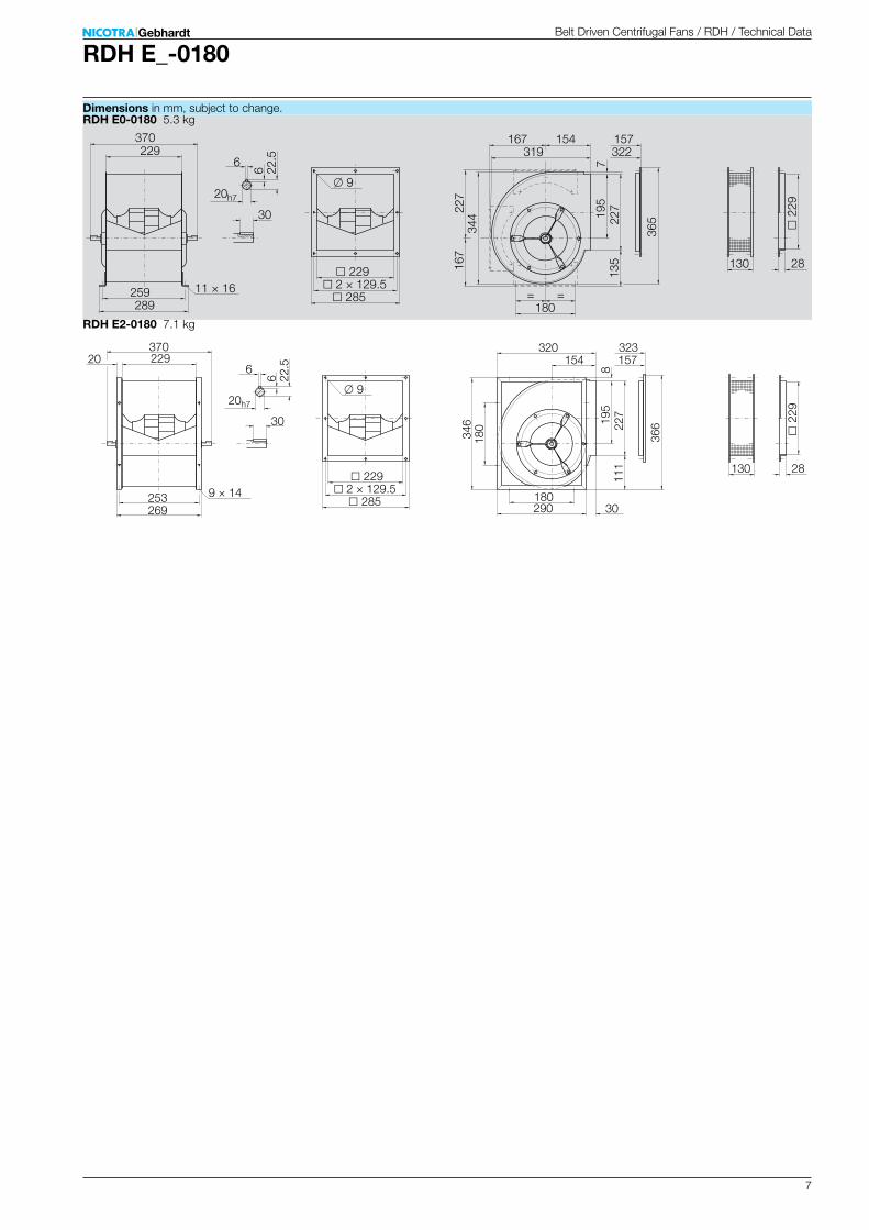
RDH E_-0180
RDH E0-0180 5.3 kg
322157
6
180
227
365
135
195
130
20h7
289259 285
229 2 × 129.5
370
9
2
29
28
344
167
11 × 16
229 319154
227
167
7
30
= =
6 22.5
RDH E2-0180 7.1 kg
323157
6
180
366
111
195
130
20h7
269253 285
229 2 × 129.5
370
9
2
29
2834
618
09 × 14
229
290
154
227
320
8
30
30
20
6 22.5
Belt Driven Centrifugal Fans / RDH / Technical Data
Dimensions in mm, subject to change.

8
RDH E_-0200
Dr 200 mmz 8J 0,006 kgm²
m 0,84 kgr1 1,2 kg/m³
2
33
16
20
40
23
5000
2500
3000
6000
3500R
DH
E0
RD
H E
2
RD
H E
4
W W
100
150
200
300
400
500
600
800
1000
1500
2000
2500
3000
3500
4000
Pa
60
80
4500
1/min
264000
304500
365500
456800
W
507600
33
16
20
40
23
26
30
36
45
50
33
16
20
40
23
26
30
36
45
50
40
m/s
Pa
m³/h
m³/s
62
29
46
67
65
59
53%
85
90
100 dB
80
75
95
kW
1.0
0.8
1.5
2.0
3.0
0.15
0.4
0.2
0.3
0.6
2 3 4 5 6 7 8 9 10 14 20
2 4 6 8 10 20 40 80 100 200 400
1 2
60
4000 5000 60003000
0.8 1.4
2000
0.6
1500
0.50.3 0.4
1000500 600 800
0.2
400
600
30
300
0.1
1
v2
qV
pd2
p F
N Pb
P r
L WA
7
ηr
SX
DX
∆LWrel4(A)
63 125 250 500 1000 2000 4000 8000 Hz
-5 -5 -5 -3 -5 -8 -11 -17 dB-5 -5 -5 -3 -5 -8 -11 -17 dB-5 -5 -5 -3 -5 -8 -11 -17 dB-4 -2 -1 -4 -6 -7 -9 -13 dB-3 -1 -2 -3 -6 -9 -9 -14 dB-0 1 -2 -4 -5 -8 -10 -18 dB-7 -4 -3 -5 -6 -6 -10 -13 dB-6 -3 -4 -4 -5 -8 -11 -11 dB-3 -2 -4 -4 -4 -8 -12 -12 dB
63 125 250 500 1000 2000 4000 8000 Hz
25 10 5 4 -6 -7 -11 -17 dB22 7 7 2 -7 -7 -12 -18 dB14 7 7 -2 -5 -8 -14 -18 dB19 11 7 1 -8 -7 -11 -17 dB16 10 6 -1 -8 -8 -13 -18 dB14 9 3 -5 -6 -9 -15 -21 dB19 7 0 -1 -8 -5 -8 -17 dB18 3 1 -1 -7 -6 -11 -16 dB10 2 1 -6 -5 -6 -15 -17 dB
1/min dB
SX 5500 5SX 4500 4SX 3000 3
qV opt 5500 4qV opt 4500 3qV opt 3000 1DX 5500 2DX 4500 2DX 3000 0
Belt Driven Centrifugal Fans / RDH / Technical Data
Technical Data
Performance Curves
Relative sound power level for inlet side LWrel7 at octave centre frequencies fc
Relative sound power level for discharge side LWrel4 at octave centre frequencies fc
Measured in installation B according to ISO 5801:
Impeller Data Impeller DataImpeller diameterNumber of bladesMoment of Inertia
Impeller weightDensity of mediaTolerance class (DIN 24166)
Please note coloured area!N all types suitableN RDH E4 onlyN do not use in this area
Performance certified is for installation type B - free inlet, ducted outlet. Power rating (kW) does not include transmission losses. Performance ratings do not include the effects of appurtenances (accessories).
Speed Duty point
Normal operation area
Nicotra Gebhardt S.p.A certifies that the fan shown herein is licensed to bear the AMCA Seal. The ratings shown are based on tests
and procedures per formed in ac-cordance with AMCA Publication 211 and comply with the requirements of the AMCA Certified Ratings Program. The AMCA Certified Ratings Seal applies to air performance ratings only.
9
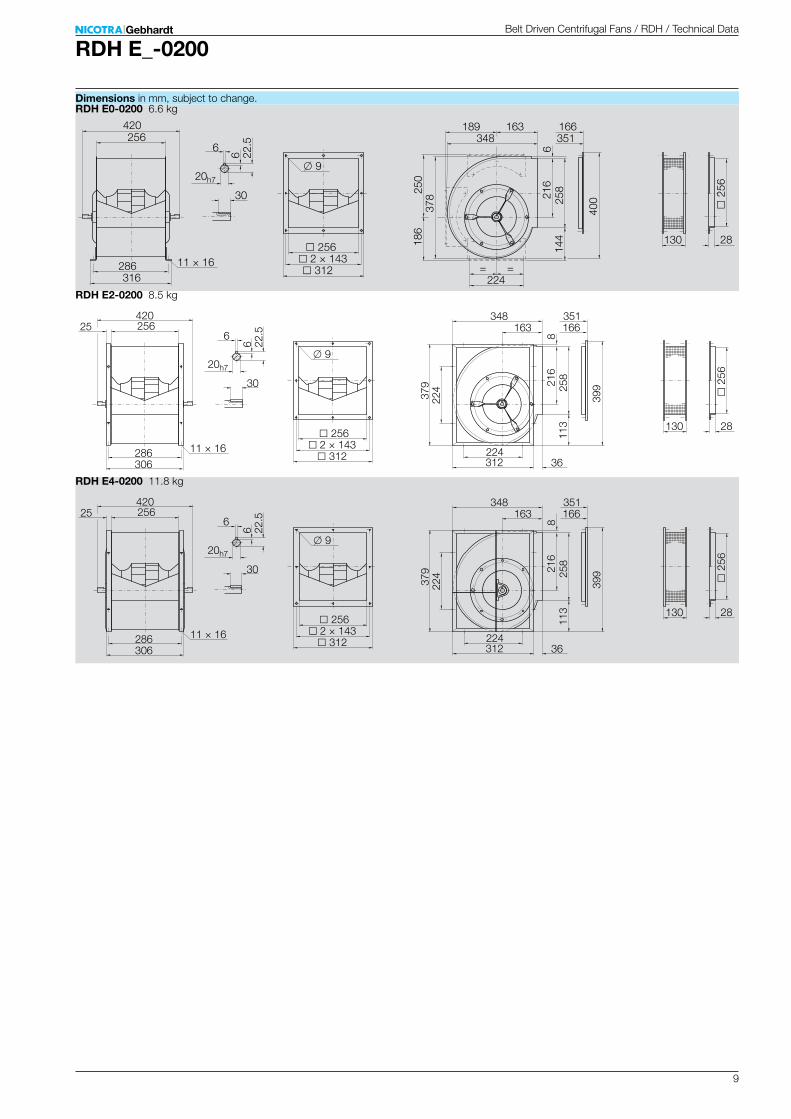
RDH E_-0200
RDH E0-0200 6.6 kg
351166
6
224
250
400
144
216
130
20h7
316286 312
256 2 × 143
420
9
2
56
28
378
186
11 × 16
256 348163
258
189
6
30
= =
6 22.5
RDH E2-0200 8.5 kg
351166
6
224
399
113
216
130
20h7
306286 312
256 2 × 143
420
9
2
56
2837
922
411 × 16
256
312
163
258
348
8
30
36
25
6 22.5
RDH E4-0200 11.8 kg
351166
6
224
399
113
216
130
20h7
306286 312
256 2 × 143
420
9
2
56
28
379
224
11 × 16
256
312
163
258
348
8
30
36
25
6 22.5
Belt Driven Centrifugal Fans / RDH / Technical Data
Dimensions in mm, subject to change.

10
RDH E_-0225
Dr 225 mmz 8J 0,011 kgm²
m 1,3 kgr1 1,2 kg/m³
2
26
13
15
33
17
2 3 4 5 6 7 8 9 10 14 20
2 3 4 5 7 10 20 40 80 100 200 400
4000
2000
2300
5000
2600R
DH
E0
RD
H E
2
RD
H E
4
1 2
m/s
Pa
m³/h
m³/s
W W
60
4000 5000 6000 80003000
100
150
200
300
400
500
600
800
1000
1500
2000
2500
3000
3500
4000
Pa
40
60
80
4500
1/min
0.8 1.4
203000
233500
2000
0.6
304500
1500
0.50.3 0.4
1000
64
35
52
69
66
5949%
85
90
70
80
75
500 600 800
0.2
385800
95 dB
W
kW
1.0
0.8
1.5
2.0
3.0
0.12
0.4
0.2
0.3 406000
26
13
15
33
17
20
23
30
3840
26
13
15
33
17
20
23
30
3840
400
436500 43 43
0.6
4.0
600
30v2
qV
pd2
p F
N Pb
P r
L WA
7
ηr
SX
DX
∆LWrel4(A)
63 125 250 500 1000 2000 4000 8000 Hz
-6 -0 0 -2 -6 -8 -13 -17 dB-4 3 -1 -2 -5 -10 -13 -19 dB4 3 1 -3 -6 -10 -14 -20 dB-6 -1 -1 -2 -6 -7 -12 -16 dB-4 2 -3 -1 -5 -9 -13 -17 dB3 1 1 -3 -5 -9 -13 -20 dB
-11 -4 -2 -4 -6 -6 -12 -16 dB-8 0 -4 -3 -4 -9 -13 -16 dB0 -1 -1 -3 -4 -10 -13 -18 dB
63 125 250 500 1000 2000 4000 8000 Hz
21 8 7 4 -7 -7 -13 -17 dB14 8 7 0 -6 -9 -14 -19 dB11 10 6 -4 -4 -10 -15 -21 dB16 11 6 1 -9 -7 -14 -21 dB12 10 3 -1 -7 -9 -18 -21 dB14 8 4 -6 -4 -12 -18 -22 dB14 6 2 0 -8 -5 -11 -20 dB10 5 1 -3 -6 -7 -15 -21 dB8 4 2 -5 -3 -10 -18 -21 dB
1/min dB
SX 5000 5SX 3500 3SX 2300 2
qV opt 5000 3qV opt 3500 1qV opt 2300 1DX 5000 2DX 3500 1DX 2300 1
Belt Driven Centrifugal Fans / RDH / Technical Data
Technical Data
Performance Curves
Measured in installation B according to ISO 5801:
Impeller Data Impeller DataImpeller diameterNumber of bladesMoment of Inertia
Impeller weightDensity of mediaTolerance class (DIN 24166)
Please note coloured area!N all types suitableN RDH E4 onlyN do not use in this area
Relative sound power level for inlet side LWrel7 at octave centre frequencies fc
Relative sound power level for discharge side LWrel4 at octave centre frequencies fc
Performance certified is for installation type B - free inlet, ducted outlet. Power rating (kW) does not include transmission losses. Performance ratings do not include the effects of appurtenances (accessories).
Speed Duty point
Normal operation area
Nicotra Gebhardt S.p.A certifies that the fan shown herein is licensed to bear the AMCA Seal. The ratings shown are based on tests
and procedures per formed in ac-cordance with AMCA Publication 211 and comply with the requirements of the AMCA Certified Ratings Program. The AMCA Certified Ratings Seal applies to air performance ratings only.

11
RDH E_-0225
RDH E0-0225 7.8 kg
391185
6
224
279
443
156
241
130
20h7
348318 344
288 2 × 159
450
9
2
88
28
422
202
11 × 16
288 388182
287
209
7
30
= =
6 22.5
RDH E2-0225 9.9 kg
393185
6
224
442
127
241
130
20h7
338318 344
288 2 × 159
450
9
2
88
2842
522
411 × 16
288
351
182
287
390
11
30
39
25
6 22.5
RDH E4-0225 13.6 kg
393185
6
224
442
127
241
130
20h7
338318 344
288 2 × 159
450
9
2
88
28
425
224
11 × 16
288
351
182
287
390
11
30
39
25
6 22.5
Belt Driven Centrifugal Fans / RDH / Technical Data
Dimensions in mm, subject to change.
12
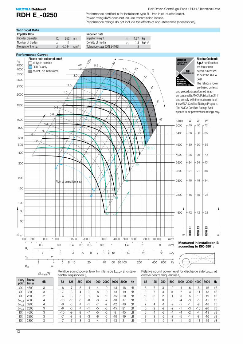
RDH E_-0250
Dr 252 mmz 11J 0,044 kgm²
m 4,87 kgr1 1,2 kg/m³
2
26
12
15
36
18
48
22
28
65
34
2 3 4 5 6 7 8 9 10 14 20
2 4 6 8 10 20 40 80 100 200 400
4000
1800
2300
5400
2800
RD
H E
0
RD
H E
2
RD
H E
4
31 2
m/s
Pa
m³/h
m³/s
W W
60
4000 5000 6000 8000 100003000
100
150
200
300
400
500
600
800
1000
1500
2000
2500
3000
3500
4000
Pa
40
60
80
4500
1/min
0.8 1.4
21 383200
24 433600
2000
0.6
30 554600
1500
0.50.3 0.4
1000
61
3146
72
76
6753%
85
90
95
80
75
500 600 800
0.2
40 726000
26
12
15
36
18
21
24
30
40
100 dB
W
kW
1.0
0.8
1.5
2.0
3.0
4.05.5
7.5
0.6
0.4
0.2
0.3
30
600
ηr
v2
qV
pd2
p F
N Pb
P r
L WA
7
SX
DX
∆LWrel4(A)
63 125 250 500 1000 2000 4000 8000 Hz
-8 -7 -5 -4 -4 -9 -13 -18 dB-7 -3 -4 0 -8 -9 -13 -19 dB-4 -3 -3 -1 -6 -10 -15 -20 dB
-10 -10 -8 -8 -3 -7 -10 -17 dB-9 -8 -7 -1 -7 -7 -12 -19 dB-8 -6 -7 -1 -5 -8 -15 -21 dB
-10 -9 -9 -7 -5 -6 -9 -15 dB-7 -8 -8 -3 -6 -6 -10 -19 dB-7 -7 -8 -3 -4 -7 -13 -21 dB
63 125 250 500 1000 2000 4000 8000 Hz
6 7 3 -2 -4 -6 -8 -16 dB9 7 3 0 -7 -4 -11 -18 dB10 6 2 -1 -3 -5 -13 -19 dB6 5 0 -5 -4 -3 -5 -15 dB7 4 -1 -2 -5 -1 -9 -18 dB6 2 -2 -2 -1 -3 -13 -20 dB5 4 -2 -4 -4 -2 -4 -13 dB7 3 -2 -2 -5 -1 -8 -16 dB6 1 -2 -3 -1 -3 -11 -19 dB
1/min dB
SX 4600 3SX 3200 3SX 2300 2
qV opt 4600 4qV opt 3200 4qV opt 2300 3DX 4600 3DX 3200 3DX 2300 3
Belt Driven Centrifugal Fans / RDH / Technical Data
Technical Data
Performance Curves
Measured in installation B according to ISO 5801:
Impeller Data Impeller DataImpeller diameterNumber of bladesMoment of Inertia
Impeller weightDensity of mediaTolerance class (DIN 24166)
Please note coloured area!N all types suitableN RDH E4 onlyN do not use in this area
Relative sound power level for inlet side LWrel7 at octave centre frequencies fc
Relative sound power level for discharge side LWrel4 at octave centre frequencies fc
Performance certified is for installation type B - free inlet, ducted outlet. Power rating (kW) does not include transmission losses. Performance ratings do not include the effects of appurtenances (accessories).
Speed Duty point
Normal operation area
Nicotra Gebhardt S.p.A certifies that the fan shown herein is licensed to bear the AMCA Seal. The ratings shown are based on tests
and procedures per formed in ac-cordance with AMCA Publication 211 and comply with the requirements of the AMCA Certified Ratings Program. The AMCA Certified Ratings Seal applies to air performance ratings only.
13
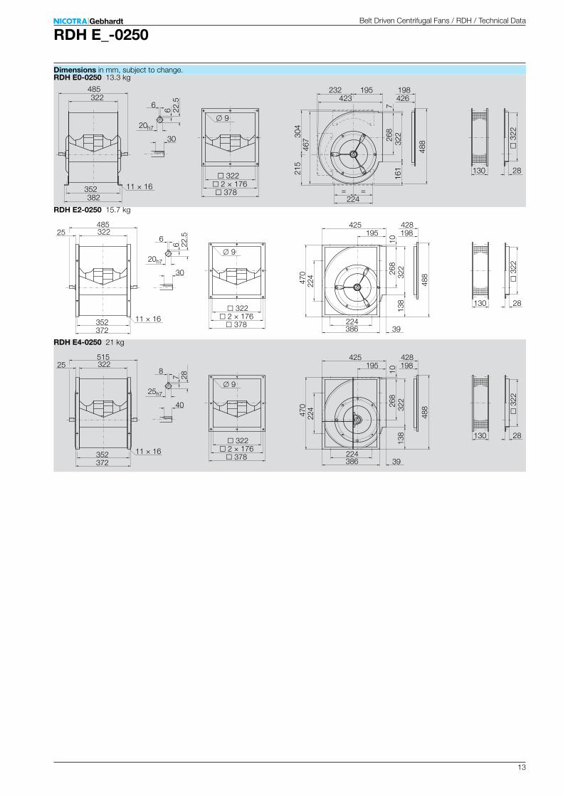
RDH E_-0250
RDH E0-0250 13.3 kg
426198
6
224
304
488
161
268
130
20h7
382352 378
322 2 × 176
485
9
3
22
28
467
215
11 × 16
322 423195
322
232
7
30
= =
6 22.5
RDH E2-0250 15.7 kg
428198
6
224
488
138
268
130
20h7
372352 378
322 2 × 176
485
9
3
22
2847
022
411 × 16
322
386
195
322
425
10
30
39
25
6 22.5
RDH E4-0250 21 kg
428198
8
224
488
138
268
130
25h7
372352 378
322 2 × 176
515
9
3
22
28
470
224
11 × 16
322
386
195
322
425
10
40
39
25
7 28
Belt Driven Centrifugal Fans / RDH / Technical Data
Dimensions in mm, subject to change.
14
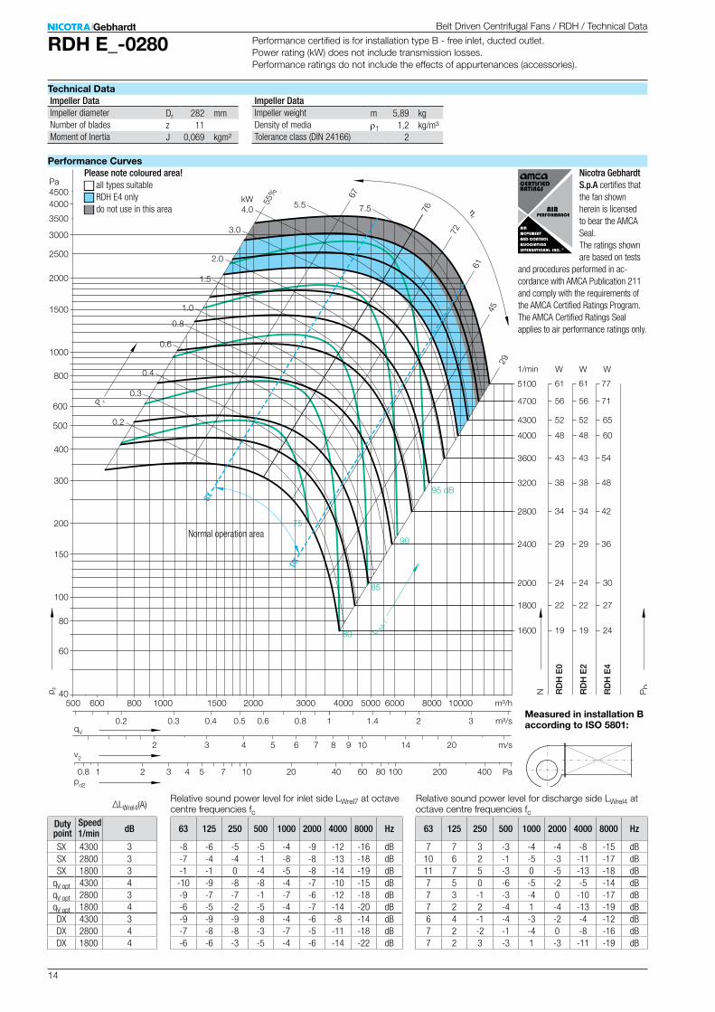
RDH E_-0280
Dr 282 mmz 11J 0,069 kgm²
m 5,89 kgr1 1,2 kg/m³
2
48
19
22
24
56
29
34
60
24
27
30
71
36
42
2 3 4 5 6 7 8 9 10 14 20
2 3 4 5 7 10 20 40 80 100 200 400
4000
1600
1800
2000
4700
2400
2800
RD
H E
0
RD
H E
2
RD
H E
4
31 2
m/s
Pa
m³/h
m³/s
W W
60
4000 5000 6000 8000 100003000
100
150
200
300
400
500
600
800
1000
1500
2000
2500
3000
3500
4000
Pa
40
60
80
4500
1/min
0.8 1.4
38 483200
43 543600
2000
0.6
52 654300
1500
0.50.3 0.4
1000
61
29
45
72
76
67
55%
85
90
95 dB
kW
1.0
0.8
1.5
2.0
3.0
4.0 5.5 7.5
0.6
80
0.4
75
500 600 800
0.2
61 775100
0.2
0.3
0.8 1
v2
qV
pd2
p F
N Pb
P r
L WA
7
ηr
SX
DX
48
19
22
24
56
29
34
W
38
43
52
61
∆LWrel4(A)
63 125 250 500 1000 2000 4000 8000 Hz
-8 -6 -5 -5 -4 -9 -12 -16 dB-7 -4 -4 -1 -8 -8 -13 -18 dB-1 -1 0 -4 -5 -8 -14 -19 dB-10 -9 -8 -8 -4 -7 -10 -15 dB-9 -7 -7 -1 -7 -6 -12 -18 dB-6 -5 -2 -5 -4 -7 -14 -20 dB-9 -9 -9 -8 -4 -6 -8 -14 dB-7 -8 -8 -3 -7 -5 -11 -18 dB-6 -6 -3 -5 -4 -6 -14 -22 dB
63 125 250 500 1000 2000 4000 8000 Hz
7 7 3 -3 -4 -4 -8 -15 dB10 6 2 -1 -5 -3 -11 -17 dB11 7 5 -3 0 -5 -13 -18 dB7 5 0 -6 -5 -2 -5 -14 dB7 3 -1 -3 -4 0 -10 -17 dB7 2 2 -4 1 -4 -13 -19 dB6 4 -1 -4 -3 -2 -4 -12 dB7 2 -2 -1 -4 0 -8 -16 dB7 2 3 -3 1 -3 -11 -19 dB
1/min dB
SX 4300 3SX 2800 3SX 1800 3
qV opt 4300 4qV opt 2800 3qV opt 1800 4DX 4300 3DX 2800 4DX 1800 4
Belt Driven Centrifugal Fans / RDH / Technical Data
Technical Data
Performance Curves
Measured in installation B according to ISO 5801:
Impeller Data Impeller DataImpeller diameterNumber of bladesMoment of Inertia
Impeller weightDensity of mediaTolerance class (DIN 24166)
Please note coloured area!N all types suitableN RDH E4 onlyN do not use in this area
Relative sound power level for inlet side LWrel7 at octave centre frequencies fc
Relative sound power level for discharge side LWrel4 at octave centre frequencies fc
Performance certified is for installation type B - free inlet, ducted outlet. Power rating (kW) does not include transmission losses. Performance ratings do not include the effects of appurtenances (accessories).
Speed Duty point
Normal operation area
Nicotra Gebhardt S.p.A certifies that the fan shown herein is licensed to bear the AMCA Seal. The ratings shown are based on tests
and procedures per formed in ac-cordance with AMCA Publication 211 and comply with the requirements of the AMCA Certified Ratings Program. The AMCA Certified Ratings Seal applies to air performance ratings only.

15
RDH E_-0280
RDH E0-0280 17.8 kg
474218
8
280
242
546
183
302
130
25h7
421391 417
361 2 × 195.5
555
9
3
61
28
524
242
11 × 16
361 471215
361
261
6
40
= =
7 28
RDH E2-0280 21 kg
475218
8
280
545
156
302
130
25h7
421391 417
361 2 × 195.5
555
9
3
61
2852
628
013 × 18
361
435
215
361
472
9
40
37
30
7 28
RDH E4-0280 28 kg
475218
8
280
545
156
302
130
30h7
421391 417
361 2 × 195.5
580
9
3
61
28
526
280
13 × 18
361
435
215
361
472
9
40
37
30
7 33
Belt Driven Centrifugal Fans / RDH / Technical Data
Dimensions in mm, subject to change.
16
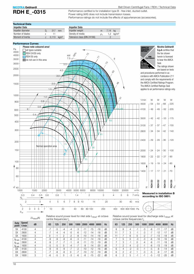
RDH E_-0315
Dr 317 mmz 11J 0,110 kgm²
m 7,14 kgr1 1,2 kg/m³
2
42
17
19
22
54
24
29
53
21
24
27
68
30
36
175
70
80
90
225
100
120
2 3 4 5 6 7 8 9 10 14 20
2 3 4 5 7 10 20 40 80 100 200 400
3500
1400
1600
1800
4500
2000
2400
RD
H E
0
RD
H E
4
RD
H E
6
3 4 5 6 71 2
m/s
Pa
m³/h
m³/s
W W W
60
4000 5000 6000 8000 10000 15000 200003000
100
150
200
300
400
500
600
800
1000
1500
2000
2500
3000
3500
4000
Pa
40
60
80
4500
1/min
0.8 1.4
34 42 1402800
37 47 1553100
2000
0.6
49 62 2054100
1500
0.5
600
30
0.3 0.4
1000
63
3148
73
77
7259%
85
90
95
100
105 dB
kW
1.0
0.8
1.5
2.0
3.0
4.0
5.5
7.5
0.6
80
0.4
75
800 1000
40v2
qV
pd2
p F
N Pb
P r
L WA
7
ηr
SX
DX
42
17
19
22
54
24
29
RD
H E
2
W
34
37
49
∆LWrel4(A)
63 125 250 500 1000 2000 4000 8000 Hz
-7 -5 -4 -4 -3 -11 -15 -18 dB-7 -4 -4 -0 -6 -12 -14 -18 dB0 -1 2 -2 -8 -10 -14 -18 dB-9 -9 -8 -6 -3 -11 -14 -18 dB-9 -7 -7 -1 -8 -11 -13 -19 dB-5 -5 0 -4 -7 -9 -14 -20 dB-9 -9 -9 -7 -2 -10 -12 -16 dB-7 -8 -8 0 -7 -10 -12 -19 dB-6 -5 0 -3 -6 -8 -15 -22 dB
63 125 250 500 1000 2000 4000 8000 Hz
8 8 4 -1 -3 -6 -11 -17 dB11 7 3 -1 -3 -7 -12 -17 dB11 7 6 0 -2 -7 -13 -18 dB7 5 0 -3 -3 -6 -10 -16 dB7 3 -1 0 -4 -6 -11 -18 dB7 2 4 -2 -1 -6 -13 -19 dB6 4 -2 -3 -1 -5 -8 -14 dB6 2 -2 1 -3 -5 -9 -17 dB6 2 5 -1 -1 -5 -12 -20 dB
1/min dB
SX 4100 4SX 2800 4SX 1600 3
qV opt 4100 4qV opt 2800 4qV opt 1600 4DX 4100 3DX 2800 3DX 1600 3
Belt Driven Centrifugal Fans / RDH / Technical Data
Technical Data
Performance Curves
Measured in installation B according to ISO 5801:
Impeller Data Impeller DataImpeller diameterNumber of bladesMoment of Inertia
Impeller weightDensity of mediaTolerance class (DIN 24166)
Please note coloured area!N all types suitableN RDH E4/E6 onlyN RDH E6 onlyN do not use in this area
Relative sound power level for inlet side LWrel7 at octave centre frequencies fc
Relative sound power level for discharge side LWrel4 at octave centre frequencies fc
Performance certified is for installation type B - free inlet, ducted outlet. Power rating (kW) does not include transmission losses. Performance ratings do not include the effects of appurtenances (accessories).
Speed Duty point
Normal operation area
Nicotra Gebhardt S.p.A certifies that the fan shown herein is licensed to bear the AMCA Seal. The ratings shown are based on tests
and procedures per formed in ac-cordance with AMCA Publication 211 and comply with the requirements of the AMCA Certified Ratings Program. The AMCA Certified Ratings Seal applies to air performance ratings only.

17
RDH E_-0315
RDH E0-0315 21 kg
525239
8
280
376
607
202
338
130
25h7
464434 460
404 2 × 217
600
9
4
04
28
586
267
11 × 16
404 522236
403
289
7
40
= =
7 28
RDH E2-0315 25 kg
527239
8
280
606
175
338
130
25h7
464434 460
404 2 × 217
600
9
4
04
2858
828
013 × 18
404
486
236
403
524
10
40
38
30
7 28
RDH E4-0315 32 kg
527239
8
280
606
175
338
130
30h7
464434 460
404 2 × 217
625
9
4
04
28
588
280
13 × 18
404
486
236
403
524
10
40
38
30
7 33
RDH E6-0315 34 kg
527239
8
280
606
175
338
130
30h7
464434 460
404 2 × 217
625
9
404
28
588
280
13 × 18
404
486
236
403
524
10
40
38
30
7 33
Belt Driven Centrifugal Fans / RDH / Technical Data
Dimensions in mm, subject to change.
18
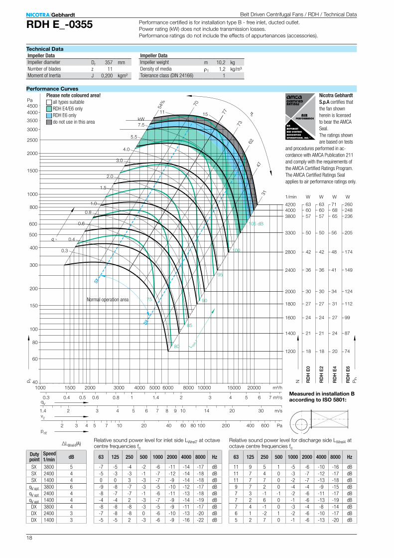
RDH E_-0355
Dr 357 mmz 11J 0,200 kgm²
m 10,2 kgr1 1,2 kg/m³
1
57
18
21
24
27
63
30
36
65
20
24
27
31
71
34
41
236
74
87
99
112
260
124
149
2 3 4 5 6 7 8 9 10 14 20
2 3 4 5 7 10 20 40 80 100 200 400
3800
1200
1400
1600
1800
4200
2000
2400
RD
H E
0
RD
H E
4
RD
H E
6
3 4 5 6 71 2
m/s
Pa
m³/h
m³/s
W W W
60
4000 5000 6000 8000 10000 15000 200003000
100
150
200
300
400
500
600
800
1000
1500
2000
2500
3000
3500
4000
Pa
40
60
80
4500
1/min
0.8 1.4
42 48 1742800
50 56 2053300
2000
0.6
60 68 2484000
1500
0.5
600
30
0.3 0.4
1000
62
3147
73
77
70
54%
85
90
95
100
105 dB
kW
1.0
0.8
1.5
2.0
3.0
4.0
5.5
7.5
11 15
0.6
80
0.4
75
1.4
0.3
57
18
21
24
27
63
30
36
RD
H E
2
W
42
50
60
v2
qV
pd2
p F
N Pb
P r
L WA
7
ηr
SX
DX
∆LWrel4(A)
63 125 250 500 1000 2000 4000 8000 Hz
-7 -5 -4 -2 -6 -11 -14 -17 dB-5 -3 -3 -1 -7 -12 -14 -18 dB0 0 3 -3 -7 -9 -14 -18 dB-9 -8 -7 -3 -5 -10 -12 -17 dB-8 -7 -7 -1 -6 -11 -13 -18 dB-4 -4 2 -3 -7 -9 -14 -19 dB-8 -8 -8 -3 -5 -9 -11 -17 dB-7 -8 -8 0 -6 -10 -13 -20 dB-5 -5 2 -3 -6 -9 -16 -22 dB
63 125 250 500 1000 2000 4000 8000 Hz
11 9 5 1 -5 -6 -10 -16 dB11 7 4 0 -3 -7 -12 -17 dB11 7 7 0 -2 -7 -13 -18 dB9 7 2 0 -4 -4 -9 -15 dB7 3 -1 -1 -2 -6 -11 -17 dB7 2 6 0 -1 -6 -13 -19 dB7 4 -1 0 -3 -4 -8 -14 dB6 1 -2 1 -2 -6 -10 -17 dB5 2 7 0 -1 -6 -13 -20 dB
1/min dB
SX 3800 5SX 2400 4SX 1400 4
qV opt 3800 6qV opt 2400 4qV opt 1400 4DX 3800 4DX 2400 3DX 1400 3
Belt Driven Centrifugal Fans / RDH / Technical Data
Technical Data
Performance Curves
Performance certified is for installation type B - free inlet, ducted outlet. Power rating (kW) does not include transmission losses. Performance ratings do not include the effects of appurtenances (accessories).
Measured in installation B according to ISO 5801:
Impeller Data Impeller DataImpeller diameterNumber of bladesMoment of Inertia
Impeller weightDensity of mediaTolerance class (DIN 24166)
Please note coloured area!N all types suitableN RDH E4/E6 onlyN RDH E6 onlyN do not use in this area
Relative sound power level for inlet side LWrel7 at octave centre frequencies fc
Relative sound power level for discharge side LWrel4 at octave centre frequencies fc
Speed Duty point
Normal operation area
Nicotra Gebhardt S.p.A certifies that the fan shown herein is licensed to bear the AMCA Seal. The ratings shown are based on tests
and procedures per formed in ac-cordance with AMCA Publication 211 and comply with the requirements of the AMCA Certified Ratings Program. The AMCA Certified Ratings Seal applies to air performance ratings only.

19
RDH E_-0355
RDH E0-0355 29 kg
585264
8
355
418
679
212
381
130
30h7
533493 509
453 2 × 241.5
675
9
4
53
28
658
281
11 × 16
453 582261
450
327
7
40
= =
7 33
RDH E2-0355 34 kg
589264
8
355
680
202
381
130
30h7
533493 509
453 2 × 241.5
675
9
4
53
2866
535
513 × 18
453
547
261
450
586
13
40
39
40
7 33
RDH E4-0355 46 kg
589264
10
355
680
202
381
130
35h7
533493 509
453 2 × 241.5
685
9
4
53
28
665
355
13 × 18
453
547
261
450
586
13
50
39
40
8 38
RDH E6-0355 47 kg
589264
10
355
680
202
381
130
35h7
533493 509
453 2 × 241.5
685
9
453
28
665
355
13 × 18
453
547
261
450
586
13
50
39
40
8 38
Belt Driven Centrifugal Fans / RDH / Technical Data
Dimensions in mm, subject to change.
20
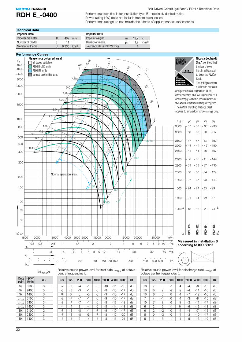
RDH E_-0400
Dr 402 mmz 11J 0,330 kgm²
m 12,7 kgr1 1,2 kg/m³
1
57
44
18
21
24
27
53
30
33
65
49
20
24
27
31
60
34
37
236
180
74
87
99
112
217
124
136
2 3 4 5 6 7 8 9 10 14 20
2 3 4 5 7 10 20 40 80 100 200 400
3800
2900
1200
1400
1600
1800
3500
2000
2200
RD
H E
0
RD
H E
4
RD
H E
6
3 4 5 6 7 8 91 2 10
m/s
Pa
m³/h
m³/s
W W W
60
4000 5000 6000 8000 10000 15000 20000 300003000
100
150
200
300
400
500
600
800
1000
1500
2000
2500
3000
3500
4000
Pa
40
60
80
4500
1/min
85
90
95
100
105 dB
kW
1.0
0.8
1.5
2.0
3.0
4.0
5.0
7.5
1115 18.5
63
3046
74
78
7158%
0.8 1.4
36 41 1492400
41 46 1672700
0.6
80
2000
0.6
0.4
75
47 53 1923100
1500
0.5
800600
30 40
57
44
18
21
24
27
53
30
33
RD
H E
2
W
36
41
47
v2
qV
pd2
p F
N Pb
P r
L WA
7
ηr
SX
DX
∆LWrel4(A)
63 125 250 500 1000 2000 4000 8000 Hz
-7 -3 -4 -1 -6 -10 -11 -16 dB-5 -3 -3 -1 -6 -8 -13 -17 dB0 0 3 -3 -6 -9 -13 -17 dB-9 -7 -7 -1 -6 -9 -10 -17 dB-8 -7 -7 -1 -6 -8 -13 -18 dB-4 -4 2 -4 -5 -8 -14 -18 dB-7 -8 -8 -1 -7 -9 -10 -17 dB-7 -8 -8 0 -7 -8 -12 -20 dB-5 -5 2 -4 -5 -8 -15 -21 dB
63 125 250 500 1000 2000 4000 8000 Hz
10 7 3 -1 -4 -4 -8 -15 dB10 6 2 -2 -2 -4 -11 -16 dB10 6 6 0 -1 -7 -12 -16 dB7 4 -1 0 -4 -3 -8 -15 dB10 7 3 0 -2 -3 -11 -17 dB6 2 6 -1 0 -6 -13 -18 dB6 2 -2 0 -4 -4 -7 -15 dB5 0 -3 0 -4 -3 -10 -17 dB5 1 6 -1 -1 -5 -13 -19 dB
1/min dB
SX 3100 3SX 2400 3SX 1400 3
qV opt 3100 3qV opt 2400 3qV opt 1400 3DX 3100 2DX 2400 3DX 1400 3
Belt Driven Centrifugal Fans / RDH / Technical Data
Technical Data
Performance Curves
Performance certified is for installation type B - free inlet, ducted outlet. Power rating (kW) does not include transmission losses. Performance ratings do not include the effects of appurtenances (accessories).
Measured in installation B according to ISO 5801:
Impeller Data Impeller DataImpeller diameterNumber of bladesMoment of Inertia
Impeller weightDensity of mediaTolerance class (DIN 24166)
Please note coloured area!N all types suitableN RDH E4/E6 onlyN RDH E6 onlyN do not use in this area
Relative sound power level for inlet side LWrel7 at octave centre frequencies fc
Relative sound power level for discharge side LWrel4 at octave centre frequencies fc
Speed Duty point
Normal operation area
Nicotra Gebhardt S.p.A certifies that the fan shown herein is licensed to bear the AMCA Seal. The ratings shown are based on tests
and procedures per formed in ac-cordance with AMCA Publication 211 and comply with the requirements of the AMCA Certified Ratings Program. The AMCA Certified Ratings Seal applies to air performance ratings only.
21
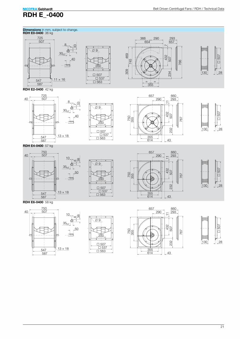
RDH E_-0400
RDH E0-0400 36 kg
200
507
657293
8
355
469
766
234
432
130
30h7
587547 563
537
725
9
5
07
28
745
309
11 × 16
507 654290
507
366
7
40
= =
7 33
RDH E2-0400 42 kg
200
507
660293
8
355
767
232
432
130
30h7
587547 563
537
725
9
5
07
2875
035
513 × 18
507
614
290
507
657
11
40
43
40
7 33
RDH E4-0400 57 kg
200
507
660293
10
355
767
232
432
130
35h7
587547 563
537
750
9
5
07
28
750
355
13 × 18
507
614
290
507
657
11
50
43
40
8 38
RDH E6-0400 58 kg
200
507
660293
10
355
767
232
432
130
35h7
587547 563
537
750
9
507
28
750
355
13 × 18
507
614
290
507
657
11
50
43
40
8 38
Belt Driven Centrifugal Fans / RDH / Technical Data
Dimensions in mm, subject to change.

22
RDH E_-0450
Dr 452 mmz 11J 0,520 kgm²
m 17,6 kgr1 1,2 kg/m³
1
58
17
20
24
27
31
54
34
37
71
21
25
29
34
38
67
42
46
272
80
96
112
128
144
256
160
176
2 3 4 5 6 7 8 9 10 14 20
2 3 4 5 7 10 20 40 80 100 200 400
3400
1000
1200
1400
1600
1800
3200
2000
2200
RD
H E
0
RD
H E
4
RD
H E
6
3 4 5 6 7 8 91 2 10
m/s
Pa
m³/h
m³/s
W W W
60
4000 5000 6000 8000 10000 15000 20000 300003000
100
150
200
300
400
500
600
800
1000
1500
2000
2500
3000
3500
4000
Pa
40
60
80
4500
1/min
85
90
95
100
105 dB
kW
1.0
0.8
1.5
2.0
3.0
4.0
5.0
7.5
11
15 22
61
3045
74
78
6851%
0.8 1.4
1.4
43 52 2002500
48 59 2242800
0.6
80
2000
0.6
0.4
75
17 21 801100
1500
0.5
58
17
20
24
27
31
54
34
37
RD
H E
2
W
43
48
17
v2
qV
pd2
p F
N Pb
P r
L WA
7
ηr
SX
DX
600
30
∆LWrel4(A)
63 125 250 500 1000 2000 4000 8000 Hz
-7 -4 -4 0 -7 -10 -13 -17 dB-3 -2 -1 -1 -6 -10 -13 -19 dB1 0 3 -3 -7 -10 -15 -20 dB-9 -7 -7 -1 -6 -9 -12 -17 dB-7 -5 -4 -1 -5 -9 -13 -19 dB-4 -4 3 -2 -6 -10 -15 -21 dB-7 -8 -8 0 -7 -9 -13 -19 dB-7 -6 -5 -1 -6 -9 -14 -21 dB-5 -5 3 -3 -6 -10 -17 -24 dB
63 125 250 500 1000 2000 4000 8000 Hz
10 6 2 0 -4 -5 -11 -16 dB10 6 3 0 -2 -6 -12 -18 dB6 0 0 1 -2 -8 -14 -20 dB6 2 -2 -2 -3 -3 -10 -16 dB6 2 0 -2 0 -5 -12 -19 dB6 2 6 2 -1 -8 -15 -21 dB6 1 -3 1 -4 -4 -10 -17 dB6 0 0 0 -1 -5 -12 -19 dB4 1 6 1 -2 -8 -15 -22 dB
1/min dB
SX 2800 3SX 2000 3SX 1200 3
qV opt 2800 3qV opt 2000 3qV opt 1200 3DX 2800 3DX 2000 3DX 1200 3
Belt Driven Centrifugal Fans / RDH / Technical Data
Technical Data
Performance Curves
Performance certified is for installation type B - free inlet, ducted outlet. Power rating (kW) does not include transmission losses. Performance ratings do not include the effects of appurtenances (accessories).
Measured in installation B according to ISO 5801:
Impeller Data Impeller DataImpeller diameterNumber of bladesMoment of Inertia
Impeller weightDensity of mediaTolerance class (DIN 24166)
Please note coloured area!N all types suitableN RDH E4/E6 onlyN RDH E6 onlyN do not use in this area
Relative sound power level for inlet side LWrel7 at octave centre frequencies fc
Relative sound power level for discharge side LWrel4 at octave centre frequencies fc
Speed Duty point
Normal operation area
Nicotra Gebhardt S.p.A certifies that the fan shown herein is licensed to bear the AMCA Seal. The ratings shown are based on tests
and procedures per formed in ac-cordance with AMCA Publication 211 and comply with the requirements of the AMCA Certified Ratings Program. The AMCA Certified Ratings Seal applies to air performance ratings only.

23
RDH E_-0450
RDH E0-0450 50 kg
200
569
735325
10
530
526
859
260
487
130
35h7
665619 625
599
815
9
5
69
28
838
344
13 × 18
569 732322
571
415
7
50
= =
8 38
RDH E2-0450 57 kg
200
569
736325
10
530
858
259
487
130
35h7
649619 625
599
815
9
5
69
2884
153
013 × 18
569
687
322
571
733
11
50
46
40
8 38
RDH E4-0450 73 kg
200
569
736325
12
530
858
259
487
130
40h7
649619 625
599
850
9
5
69
28
841
530
13 × 18
569
687
322
571
733
11
70
46
40
8 43
RDH E6-0450 75 kg
200
569
736325
12
530
858
259
487
130
40h7
649619 625
599
850
9
569
28
841
530
13 × 18
569
687
322
571
733
11
70
46
40
8 43
Belt Driven Centrifugal Fans / RDH / Technical Data
Dimensions in mm, subject to change.

24
RDH E_-0500
Dr 502 mmz 11J 0,890 kgm²
m 23,5 kgr1 1,2 kg/m³
1
15
17
20
24
27
31
51
36
40
19
21
25
29
34
38
63
44
49
72
80
96
112
128
144
240
168
188
132
146
176
205
234
263
439
307
344
2 3 4 5 6 7 8 9 10 14 20
2 3 4 5 7 10 20 40 80 100 200 400
900
1000
1200
1400
1600
1800
3000
2100
2350
RD
H E
0/E
2
RD
H E
4
RD
H E
6
RD
H E
7
3 4 5 6 7 8 91 2 1410
m/s
Pa
m³/h
m³/s
W W W W
60
4000 5000 6000 8000 10000 15000 20000 30000 400003000
100
150
200
300
400
500
600
800
1000
1500
2000
2500
3000
3500
4000
Pa
40
60
80
4500
1/min
85
90
95
100
105 dB
kW
1.0
0.8
1.5
2.0
3.0
4.0
6.0
8.0
11
15
22
62
2945
75
80
6951%
0.8 1.4
1.4
45 56 212 388265048 59 224 4102800
0.6
80
2000
0.6
30
600
v2
qV
pd2
p F
N Pb
P r
L WA
7
ηr
SX
DX
∆LWrel4(A)
63 125 250 500 1000 2000 4000 8000 Hz
-6 -4 -4 1 -9 -13 -14 -18 dB-1 -1 0 -2 -9 -11 -15 -18 dB2 2 2 -5 -7 -11 -14 -18 dB-9 -7 -8 1 -9 -12 -14 -19 dB-6 -5 -2 -1 -8 -10 -15 -19 dB-2 -1 2 -4 -7 -11 -15 -19 dB-8 -8 -8 1 -7 -11 -13 -19 dB-6 -6 -3 -1 -7 -9 -14 -19 dB-3 -2 2 -3 -6 -10 -15 -21 dB
63 125 250 500 1000 2000 4000 8000 Hz
9 5 1 1 -6 -8 -13 -17 dB10 6 4 0 -4 -8 -13 -18 dB10 7 5 0 -3 -9 -13 -18 dB8 5 1 1 -5 -7 -12 -18 dB10 6 4 0 -3 -7 -13 -18 dB5 3 5 1 -3 -9 -14 -19 dB5 0 -3 1 -4 -6 -10 -16 dB6 1 2 0 -2 -6 -12 -17 dB5 4 5 1 -3 -8 -13 -20 dB
1/min dB
SX 2600 2SX 1800 3SX 1000 3
qV opt 2600 1qV opt 1800 2qV opt 1000 3DX 2600 2DX 1800 3DX 1000 3
Belt Driven Centrifugal Fans / RDH / Technical Data
Technical Data
Performance Curves
Performance certified is for installation type B - free inlet, ducted outlet. Power rating (kW) does not include transmission losses. Performance ratings do not include the effects of appurtenances (accessories).
Measured in installation B according to ISO 5801:
Impeller Data Impeller DataImpeller diameterNumber of bladesMoment of Inertia
Impeller weightDensity of mediaTolerance class (DIN 24166)
Please note coloured area!N all types suitableN RDH E4/E6/E7 onlyN RDH E6/E7 onlyN RDH E7 onlyN do not use in this area
Relative sound power level for inlet side LWrel7 at octave centre frequencies fc
Relative sound power level for discharge side LWrel4 at octave centre frequencies fc
Speed Duty point
Normal operation area
Nicotra Gebhardt S.p.A certifies that the fan shown herein is licensed to bear the AMCA Seal. The ratings shown are based on tests
and procedures per formed in ac-cordance with AMCA Publication 211 and comply with the requirements of the AMCA Certified Ratings Program. The AMCA Certified Ratings Seal applies to air performance ratings only.
25
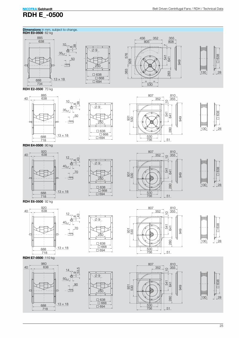
RDH E_-0500
RDH E0-0500 62 kg
250
638
808355
10
530
576
949
283
541
130
35h7
734688 694
668
885
9
6
38
28
928
383
13 × 18
638 805352
641
456
7
50
= =
8 38
RDH E2-0500 70 kg
250
638
810355
10
530
949
280
541
130
35h7
718688 694
668
885
9
6
38
2893
153
013 × 18
638
756
352
641
807
10
50
51
40
8 38
RDH E4-0500 90 kg
250
638
810355
12
530
949
280
541
130
40h7
718688 694
668
920
9
6
38
28
931
530
13 × 18
638
756
352
641
807
10
70
51
40
8 43
RDH E6-0500 92 kg
250
638
810355
12
530
949
280
541
130
40h7
718688 694
668
920
9
638
28
931
530
13 × 18
638
756
352
641
807
10
70
51
40
8 43
RDH E7-0500 110 kg
250
638
810355
14
530
949
280
541
130
50h7
718688 694
668
960
9
6
38
28
931
530
13 × 18
638
756
352
641
807
10
90
51
40
9 53.5
Belt Driven Centrifugal Fans / RDH / Technical Data
Dimensions in mm, subject to change.
26
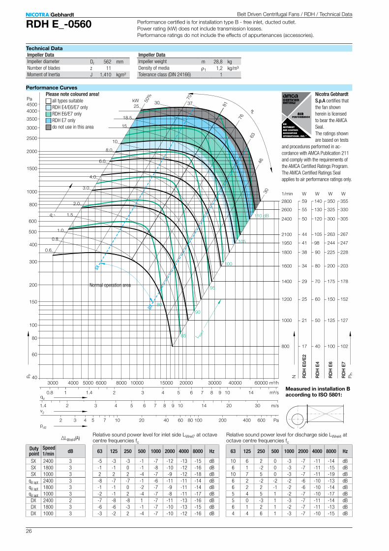
RDH E_-0560
Dr 562 mmz 11J 1,410 kgm²
m 28,8 kgr1 1,2 kg/m³
1
17
21
25
29
34
38
41
44
50
40
50
60
70
80
90
98
105
120
100
125
150
175
200
225
244
263
300
102
127
152
178
203
228
247
267
305
2 3 4 5 6 7 8 9 10 14 20
2 3 4 5 7 10 20 40 80 100 200 400
800
1000
1200
1400
1600
1800
1950
2100
2400
RD
H E
0/E
2
RD
H E
4
RD
H E
6
RD
H E
7
3 4 5 6 7 8 91 2 1410
m/s
Pa
m³/h
m³/s
W W W W
60
4000 5000 6000 8000 10000 15000 20000 30000 40000 600003000
100
150
200
300
400
500
600
800
1000
1500
2000
2500
3000
3500
4000
Pa
40
60
80
4500
1/min
85
90
95
100
105
kW
1.0
0.8
1.5
2.0
3.0
4.0
6.0
8.0
10
15
18.5
2530 37
63
3046
76
81
70
50%
0.8 1.4
1.4
55 130 325 3302600
59 140 350 3552800
0.6
80
110 dB
30
600
v2
qV
pd2
p F
N Pb
P r
L WA
7
ηr
SX
DX
∆LWrel4(A)
63 125 250 500 1000 2000 4000 8000 Hz
-5 -3 -3 -1 -7 -12 -13 -15 dB-1 -1 0 -1 -8 -10 -12 -16 dB2 2 2 -4 -7 -9 -12 -18 dB-8 -7 -7 -1 -6 -11 -11 -14 dB-1 -1 0 -2 -7 -9 -11 -14 dB-2 -1 2 -4 -7 -8 -11 -17 dB-7 -8 -8 1 -7 -11 -13 -16 dB-6 -6 -3 -1 -7 -10 -13 -15 dB-3 -2 2 -4 -7 -10 -12 -16 dB
63 125 250 500 1000 2000 4000 8000 Hz
10 6 2 0 -3 -7 -11 -14 dB6 1 -2 0 -3 -7 -11 -15 dB10 7 5 0 -3 -7 -11 -19 dB6 2 -2 -2 -2 -6 -10 -13 dB6 2 2 -1 -2 -6 -10 -14 dB5 4 5 1 -2 -7 -10 -17 dB5 0 -3 1 -3 -7 -11 -14 dB6 1 2 1 -2 -7 -11 -13 dB4 4 6 1 -3 -7 -10 -15 dB
1/min dB
SX 2400 3SX 1800 3SX 1000 3
qV opt 2400 3qV opt 1800 3qV opt 1000 3DX 2400 2DX 1800 3DX 1000 3
Belt Driven Centrifugal Fans / RDH / Technical Data
Technical Data
Performance Curves
Performance certified is for installation type B - free inlet, ducted outlet. Power rating (kW) does not include transmission losses. Performance ratings do not include the effects of appurtenances (accessories).
Measured in installation B according to ISO 5801:
Impeller Data Impeller DataImpeller diameterNumber of bladesMoment of Inertia
Impeller weightDensity of mediaTolerance class (DIN 24166)
Please note coloured area!N all types suitableN RDH E4/E6/E7 onlyN RDH E6/E7 onlyN RDH E7 onlyN do not use in this area
Relative sound power level for inlet side LWrel7 at octave centre frequencies fc
Relative sound power level for discharge side LWrel4 at octave centre frequencies fc
Speed Duty point
Normal operation area
Nicotra Gebhardt S.p.A certifies that the fan shown herein is licensed to bear the AMCA Seal. The ratings shown are based on tests
and procedures per formed in ac-cordance with AMCA Publication 211 and comply with the requirements of the AMCA Certified Ratings Program. The AMCA Certified Ratings Seal applies to air performance ratings only.

27
RDH E_-0560
RDH E0-0560 79 kg
250
715
900393
12
530
643
1058
315
606
130
40h7
811765 771
745
1000
9
7
15
28
1037
425
13 × 18
715 897390
716
511
7
70
= =
8 43
RDH E2-0560 92 kg
250
715
904393
12
530
1061
317
606
130
40h7
815765 771
745
1000
9
7
15
2810
4653
013 × 18
715
851
390
716
901
13
70
50
50
8 43
RDH E4-0560 141 kg
250
715
904393
14
530
1061
317
606
130
50h7
815765 771
745
1070
9
7
15
28
1046
530
13 × 18
715
851
390
716
901
13
90
50
50
9 53.5
RDH E6-0560 148 kg
250
715
904393
14
530
1061
317
606
130
50h7
815765 771
745
1070
9
715
28
1046
530
13 × 18
715
851
390
716
901
13
90
50
50
9 53.5
RDH E7-0560 153 kg
250
715
904393
14
530
1061
317
606
130
50h7
815765 771
745
1130
9
7
15
28
1046
530
13 × 18
715
851
390
716
901
13
90
50
50
9 53.5
Belt Driven Centrifugal Fans / RDH / Technical Data
Dimensions in mm, subject to change.
28
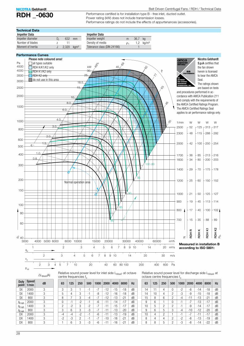
RDH _-0630
Dr 632 mmz 11J 2,320 kgm²
m 36,7 kgr1 1,2 kg/m³
1
15
17
19
21
25
29
34
36
42
48
52
35
40
45
50
60
70
80
85
100
115
125
88
100
113
125
150
175
200
213
250
288
313
89
102
114
127
152
178
203
216
254
292
317
2 3 4 5 6 7 8 9 10 14 20 30
2 3 4 5 7 10 20 40 80 100 200 400
80
85
90
95
100 dB
kW
1.0
0.8
1.5
2.0
3.0
4.0
6.0
8.0
10
15
18.5
25
3045
700
800
900
1000
1200
1400
1600
1700
2000
2300
2500
63
3046
77
82
69
49%
600
RD
H R
RD
H K
RD
H K
1
RD
H K
2
3 4 5 6 7 8 91 2 201410
m/s
Pa
m³/h
m³/s
W W W W
60
4000 5000 6000 8000 10000 15000 20000 30000 40000 600003000
100
150
200
300
400
500
600
800
1000
1500
2000
2500
3000
3500
4000
Pa
40
60
80
4500
1/min
v2
qV
pd2
p F
N Pb
P r
L WA
7
ηr
SX
DX
∆LWrel4(A)
63 125 250 500 1000 2000 4000 8000 Hz
3 3 1 -1 -7 -12 -15 -18 dB5 4 3 -1 -8 -12 -16 -18 dB8 7 3 -4 -7 -12 -13 -21 dB0 -1 -2 -1 -6 -11 -14 -17 dB2 -2 3 -2 -7 -11 -15 -17 dB3 6 3 -3 -7 -11 -13 -20 dB-4 -4 -2 -1 -6 -11 -13 -19 dB-2 -3 2 -1 -7 -10 -16 -21 dB1 6 3 -3 -6 -11 -16 -21 dB
63 125 250 500 1000 2000 4000 8000 Hz
14 11 4 0 -2 -8 -14 -18 dB14 10 4 2 -3 -9 -15 -18 dB15 8 6 2 -4 -11 -13 -21 dB9 6 1 0 -1 -7 -13 -17 dB10 5 2 2 -1 -9 -14 -17 dB9 6 5 3 -4 -10 -12 -20 dB10 4 2 1 -1 -7 -11 -17 dB8 4 4 2 -2 -8 -13 -19 dB8 8 5 2 -3 -8 -14 -22 dB
1/min dB
SX 2000 3SX 1400 3SX 800 3
qV opt 2000 3qV opt 1400 3qV opt 800 3DX 2000 3DX 1400 3DX 800 3
Belt Driven Centrifugal Fans / RDH / Technical Data
Technical Data
Performance Curves
Performance certified is for installation type B - free inlet, ducted outlet. Power rating (kW) does not include transmission losses. Performance ratings do not include the effects of appurtenances (accessories).
Measured in installation B according to ISO 5801:
Impeller Data Impeller DataImpeller diameterNumber of bladesMoment of Inertia
Impeller weightDensity of mediaTolerance class (DIN 24166)
Please note coloured area!N all types suitableN RDH K/K1/K2 onlyN RDH K1/K2 onlyN RDH K2 onlyN do not use in this area
Relative sound power level for inlet side LWrel7 at octave centre frequencies fc
Relative sound power level for discharge side LWrel4 at octave centre frequencies fc
Speed Duty point
Normal operation area
Nicotra Gebhardt S.p.A certifies that the fan shown herein is licensed to bear the AMCA Seal. The ratings shown are based on tests
and procedures per formed in ac-cordance with AMCA Publication 211 and comply with the requirements of the AMCA Certified Ratings Program. The AMCA Certified Ratings Seal applies to air performance ratings only.
29
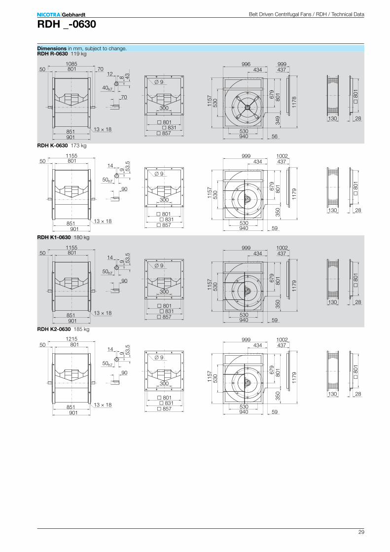
RDH _-0630
RDH R-0630 119 kg
300
801
999437
12
530
1178
349
679
130
40h7
901851 857
831
1085
9
8
01
28
1157
530
13 × 18
801
940
434
801
99670
56
50
70
8 43
RDH K-0630 173 kg
300
801
1002437
14
530
1179
350
679
130
50h7
901851 857
831
1155
9
8
01
2811
5753
013 × 18
801
940
434
801
999
90
59
50
9 53.5
RDH K1-0630 180 kg
300
801
1002437
14
530
1179
350
679
130
50h7
901851 857
831
1155
9
8
01
28
1157
530
13 × 18
801
940
434
801
999
90
59
50
9 53.5
RDH K2-0630 185 kg
300
801
1002437
14
530
1179
350
679
130
50h7
901851 857
831
1215
9
801
28
1157
530
13 × 18
801
940
434
801
999
90
59
50
9 53.5
Belt Driven Centrifugal Fans / RDH / Technical Data
Dimensions in mm, subject to change.

30
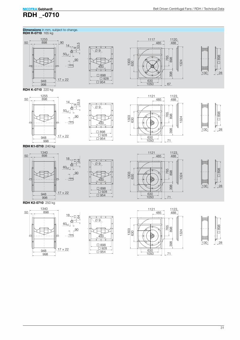
RDH _-0710
Dr 712 mmz 11J 4,940 kgm²
m 60 kgr1 1,2 kg/m³
1
100
150
200
300
400
500
600
800
1000
1500
2000
2500
3000
3500
4000
Pa
40
60
80
5000 6000 8000 10000 15000 20000 30000 40000 60000 80000
4500
2 3 4 5 6 7 8 9 10 14 20 30
2 4 6 8 10 20 40 80 100 200 400 600
3 4 5 6 7 8 92 201410
m/s
Pa
m³/h
m³/s
60
1.4
800
12
2200
2000
1700
1500
1300
1200
1100
1000
900
800
700
110
100
85
75
65
60
55
50
45
40
35
372
338
287
254
220
203
186
169
152
135
118
129
117
100
88
76
70
64
59
53
47
41
110
100
85
75
65
60
55
50
45
40
35
RD
H R
RD
H K
RD
H K
1
RD
H K
2
W W W W
1.5
80
85
90
95
100
105 dB
1/min
kW
1.5
2.0
3.0
4.0
6.0
8.0
10
15
22
3745 55
25
64
3046
78
83
71
50%
v2
qV
pd2
p F
N Pb
P r
L WA
7
ηr
SX
DX
∆LWrel4(A)
63 125 250 500 1000 2000 4000 8000 Hz
1 1 0 0 -8 -11 -14 -19 dB3 2 3 -2 -8 -10 -15 -19 dB6 7 3 -4 -6 -11 -15 -19 dB-1 -1 -1 -0 -7 -10 -14 -19 dB0 0 3 -3 -7 -9 -15 -19 dB4 7 2 -4 -6 -11 -15 -20 dB-1 -1 -1 0 -8 -10 -14 -21 dB1 0 4 -3 -8 -9 -16 -22 dB4 7 2 -4 -5 -12 -18 -23 dB
63 125 250 500 1000 2000 4000 8000 Hz
11 8 3 1 -3 -7 -13 -19 dB11 8 4 1 -3 -7 -14 -19 dB12 8 5 1 -3 -10 -15 -19 dB7 6 2 0 -2 -6 -13 -18 dB8 6 3 0 -2 -7 -14 -19 dB10 7 4 2 -3 -10 -15 -20 dB12 7 3 1 -3 -6 -12 -19 dB11 7 6 0 -2 -7 -14 -21 dB11 9 4 2 -2 -10 -16 -23 dB
1/min dB
SX 2000 3SX 1500 3SX 800 3
qV opt 2000 3qV opt 1500 3qV opt 800 3DX 2000 3DX 1500 3DX 800 3
Belt Driven Centrifugal Fans / RDH / Technical Data
Technical Data
Performance Curves
Performance certified is for installation type B - free inlet, ducted outlet. Power rating (kW) does not include transmission losses. Performance ratings do not include the effects of appurtenances (accessories).
Measured in installation B according to ISO 5801:
Impeller Data Impeller DataImpeller diameterNumber of bladesMoment of Inertia
Impeller weightDensity of mediaTolerance class (DIN 24166)
Please note coloured area!N all types suitableN RDH K/K1/K2 onlyN RDH K1/K2 onlyN RDH K2 onlyN do not use in this area
Relative sound power level for inlet side LWrel7 at octave centre frequencies fc
Relative sound power level for discharge side LWrel4 at octave centre frequencies fc
Speed Duty point
Normal operation area
Nicotra Gebhardt S.p.A certifies that the fan shown herein is licensed to bear the AMCA Seal. The ratings shown are based on tests
and procedures per formed in ac-cordance with AMCA Publication 211 and comply with the requirements of the AMCA Certified Ratings Program. The AMCA Certified Ratings Seal applies to air performance ratings only.
31
RDH _-0710
RDH R-0710 165 kg
400
898
1120488
14
630
1324
398
765
130
50h7
998948 954
928
1255
9
8
98
28
1303
630
17 × 22
898
1050
485
898
111790
67
50
90
9 53.5
RDH K-0710 220 kg
400
898
1123488
14
630
1324
398
765
130
50h7
998948 954
928
1255
9
8
98
2813
0363
017 × 22
898
1050
485
898
1121
90
71
50
9 53.5
RDH K1-0710 240 kg
400
898
1123488
18
630
1324
398
765
130
60h7
998948 954
928
1340
9
8
98
28
1303
630
17 × 22
898
1050
485
898
1121
90
71
50
11 64
RDH K2-0710 250 kg
400
898
1123488
18
630
1324
398
765
130
60h7
998948 954
928
1340
9
898
28
1303
630
17 × 22
898
1050
485
898
1121
90
71
50
11 64
Belt Driven Centrifugal Fans / RDH / Technical Data
Dimensions in mm, subject to change.
32
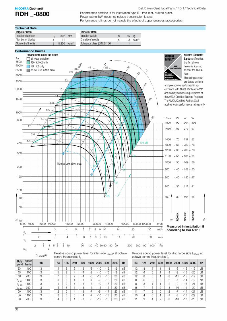
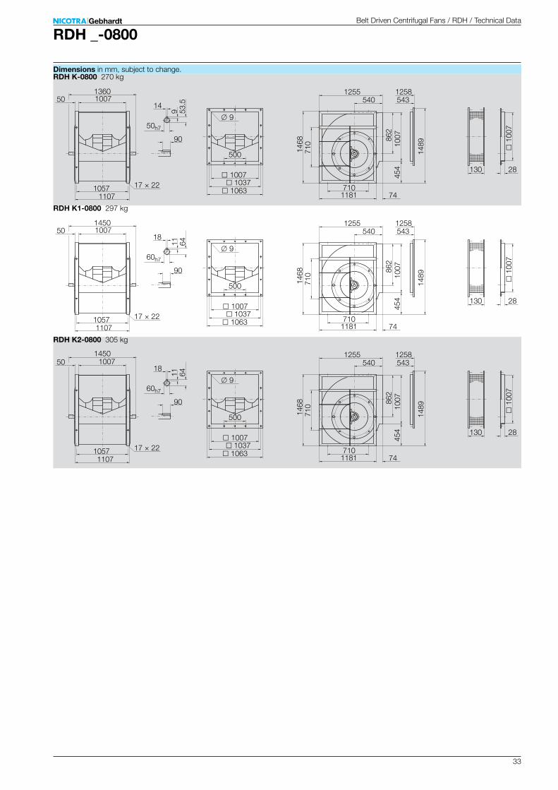
RDH _-0800
Dr 802 mmz 11J 8,250 kgm²
m 86 kgr1 1,2 kg/m³
1
3 4 5 6 7 8 92 10 14 20 30
3 4 5 6 7 8 92 10 14 20 30
3 4 5 6 82 10 30 40 50 60 8020 100 300 400 600200
600
700
800
900
1000
1100
1200
1300
1400
1650
1800
30
35
40
45
50
55
60
65
70
83
90
101
118
135
152
169
186
203
220
237
279
304
35
41
47
53
58
64
70
76
82
97
105
85
90
95
100
kW
1.5
2.0
3.0
4.0
6.0
8.0
11
15
22
3745 55
64
3046
78
83
71
50%
80
105 dB
m/s
Pa
m³/h
m³/s
100
150
200
300
400
800
1000
1500
2000
2500
3000
3500
4000
Pa
40
60
80
4500
5000 6000 8000 10000 15000 20000 30000 40000 60000 80000 100000
RD
H K
RD
H K
1
RD
H K
2
W W W1/min
v2
qV
pd2
p F
N Pb
P r
L WA
7
ηr
SX
DX
∆LWrel4(A)
63 125 250 500 1000 2000 4000 8000 Hz
4 3 3 -2 -8 -10 -16 -19 dB5 3 4 -4 -8 -10 -16 -19 dB7 8 2 -4 -6 -12 -15 -20 dB0 0 4 -3 -7 -9 -15 -20 dB1 0 4 -3 -7 -10 -16 -20 dB4 8 1 -3 -6 -12 -16 -20 dB2 0 4 -3 -7 -9 -17 -23 dB2 0 5 -4 -7 -10 -18 -23 dB4 8 1 -3 -5 -12 -18 -23 dB
63 125 250 500 1000 2000 4000 8000 Hz
12 8 4 1 -3 -8 -15 -19 dB12 6 5 1 -3 -8 -15 -20 dB12 8 5 1 -3 -11 -15 -19 dB8 6 3 0 -2 -7 -14 -19 dB8 3 4 1 -2 -9 -15 -21 dB9 7 4 2 -3 -10 -15 -20 dB11 7 5 0 -2 -7 -14 -21 dB10 4 6 1 -3 -8 -16 -22 dB11 9 4 2 -3 -10 -17 -23 dB
1/min dB
SX 1400 3SX 1100 3SX 700 3
qV opt 1400 3qV opt 1100 3qV opt 700 3DX 1400 3DX 1100 3DX 700 3
Belt Driven Centrifugal Fans / RDH / Technical Data
Technical Data
Performance Curves
Performance certified is for installation type B - free inlet, ducted outlet. Power rating (kW) does not include transmission losses. Performance ratings do not include the effects of appurtenances (accessories).
Measured in installation B according to ISO 5801:
Impeller Data Impeller DataImpeller diameterNumber of bladesMoment of Inertia
Impeller weightDensity of mediaTolerance class (DIN 24166)
Please note coloured area!N all types suitableN RDH K1/K2 onlyN RDH K2 onlyN do not use in this area
Relative sound power level for inlet side LWrel7 at octave centre frequencies fc
Relative sound power level for discharge side LWrel4 at octave centre frequencies fc
Speed Duty point
Normal operation area
Nicotra Gebhardt S.p.A certifies that the fan shown herein is licensed to bear the AMCA Seal. The ratings shown are based on tests
and procedures per formed in ac-cordance with AMCA Publication 211 and comply with the requirements of the AMCA Certified Ratings Program. The AMCA Certified Ratings Seal applies to air performance ratings only.
33
RDH _-0800
RDH K-0800 270 kg
500
1007
1258543
14
710
1489
454
862
130
50h7
11071057 1063
1037
1360
9
1
007
28
1468
710
17 × 22
1007
1181
540
1007
1255
90
74
50
9 53.5
RDH K1-0800 297 kg
500
1007
1258543
18
710
1489
454
862
130
60h7
11071057 1063
1037
1450
9
1
007
2814
6871
017 × 22
1007
1181
540
1007
1255
90
74
50
11 64
RDH K2-0800 305 kg
500
1007
1258543
18
710
1489
454
862
130
60h7
11071057 1063
1037
1450
9
1
007
28
1468
710
17 × 22
1007
1181
540
1007
1255
74
50
90
11 64
Belt Driven Centrifugal Fans / RDH / Technical Data
Dimensions in mm, subject to change.
34
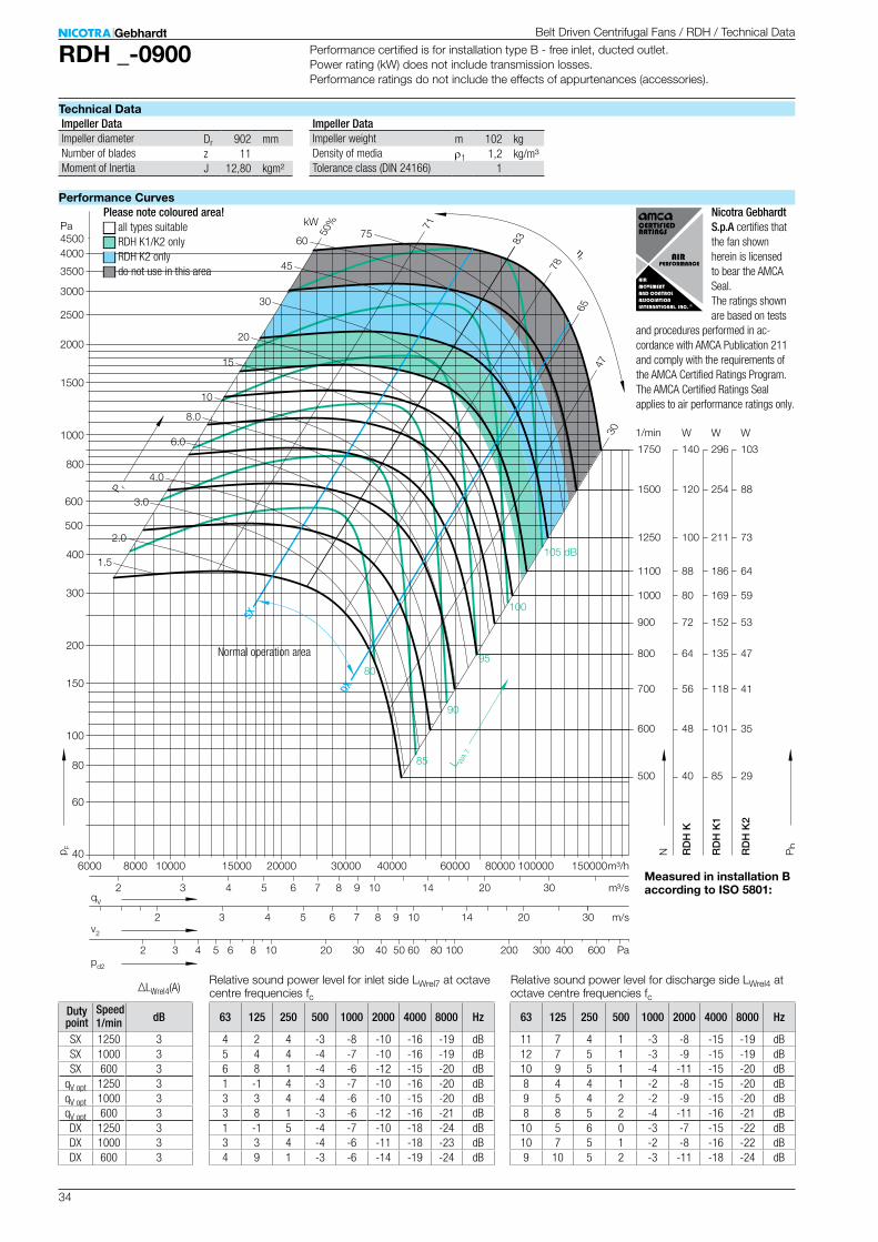
RDH _-0900
Dr 902 mmz 11J 12,80 kgm²
m 102 kgr1 1,2 kg/m³
1
100
150
200
300
400
500
600
800
1000
1500
2000
2500
3000
3500
4000
Pa
40
60
80
6000 8000 10000 15000 20000 30000 40000 60000 80000
4500
100000 150000
500
600
700
800
900
1000
1100
1250
1500
1750
40
48
56
64
72
80
88
100
120
140
85
101
118
135
152
169
186
211
254
296
29
35
41
47
53
59
64
73
88
103
85
90
95
100
kW
1.5
2.0
3.0
4.0
6.0
8.0
10
15
20
30
45
60
65
3047
78
83
71
50%
80
105 dB
RD
H K
RD
H K
1
RD
H K
2
W W W1/min
75
3 4 5 6 7 8 92 10 14 20 30
3 4 5 6 7 8 92 10 14 20 30
3 4 5 6 82 10 30 40 50 60 8020 100 300 400 600200
m/s
Pa
m³/h
m³/s
v2
qV
pd2
p F
N Pb
P r
L WA
7
ηr
SX
DX
∆LWrel4(A)
63 125 250 500 1000 2000 4000 8000 Hz
4 2 4 -3 -8 -10 -16 -19 dB5 4 4 -4 -7 -10 -16 -19 dB6 8 1 -4 -6 -12 -15 -20 dB1 -1 4 -3 -7 -10 -16 -20 dB3 3 4 -4 -6 -10 -15 -20 dB3 8 1 -3 -6 -12 -16 -21 dB1 -1 5 -4 -7 -10 -18 -24 dB3 3 4 -4 -6 -11 -18 -23 dB4 9 1 -3 -6 -14 -19 -24 dB
63 125 250 500 1000 2000 4000 8000 Hz
11 7 4 1 -3 -8 -15 -19 dB12 7 5 1 -3 -9 -15 -19 dB10 9 5 1 -4 -11 -15 -20 dB8 4 4 1 -2 -8 -15 -20 dB9 5 4 2 -2 -9 -15 -20 dB8 8 5 2 -4 -11 -16 -21 dB10 5 6 0 -3 -7 -15 -22 dB10 7 5 1 -2 -8 -16 -22 dB9 10 5 2 -3 -11 -18 -24 dB
1/min dB
SX 1250 3SX 1000 3SX 600 3
qV opt 1250 3qV opt 1000 3qV opt 600 3DX 1250 3DX 1000 3DX 600 3
Belt Driven Centrifugal Fans / RDH / Technical Data
Technical Data
Performance Curves
Performance certified is for installation type B - free inlet, ducted outlet. Power rating (kW) does not include transmission losses. Performance ratings do not include the effects of appurtenances (accessories).
Measured in installation B according to ISO 5801:
Impeller Data Impeller DataImpeller diameterNumber of bladesMoment of Inertia
Impeller weightDensity of mediaTolerance class (DIN 24166)
Please note coloured area!N all types suitableN RDH K1/K2 onlyN RDH K2 onlyN do not use in this area
Relative sound power level for inlet side LWrel7 at octave centre frequencies fc
Relative sound power level for discharge side LWrel4 at octave centre frequencies fc
Speed Duty point
Normal operation area
Nicotra Gebhardt S.p.A certifies that the fan shown herein is licensed to bear the AMCA Seal. The ratings shown are based on tests
and procedures per formed in ac-cordance with AMCA Publication 211 and comply with the requirements of the AMCA Certified Ratings Program. The AMCA Certified Ratings Seal applies to air performance ratings only.
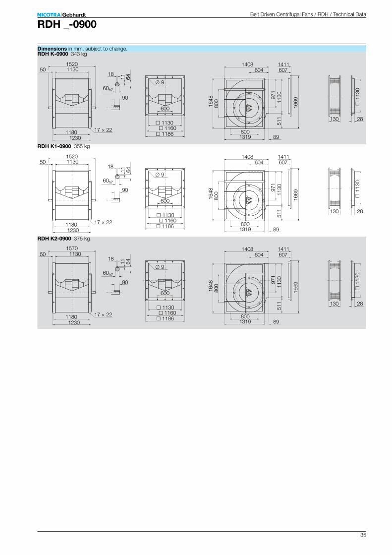
35
RDH _-0900
RDH K-0900 343 kg
600
1130
1411607
18
800
1669
511
971
130
60h7
12301180 1186
1160
1520
9
1
130
28
1648
800
17 × 22
1130
1319
604
1130
1408
90
89
50
11 6411 64
RDH K1-0900 355 kg
600
1130
1411607
18
800
1669
511
971
130
60h7
12301180 1186
1160
1520
9
1
130
2816
4880
017 × 22
1130
1319
604
1130
1408
90
89
50
11 64
RDH K2-0900 375 kg
600
1130
1411607
18
800
1669
511
971
130
60h7
12301180 1186
1160
1570
9
1
130
28
1648
800
17 × 22
1130
1319
604
1130
1408
89
50
90
11 64
Belt Driven Centrifugal Fans / RDH / Technical Data
Dimensions in mm, subject to change.
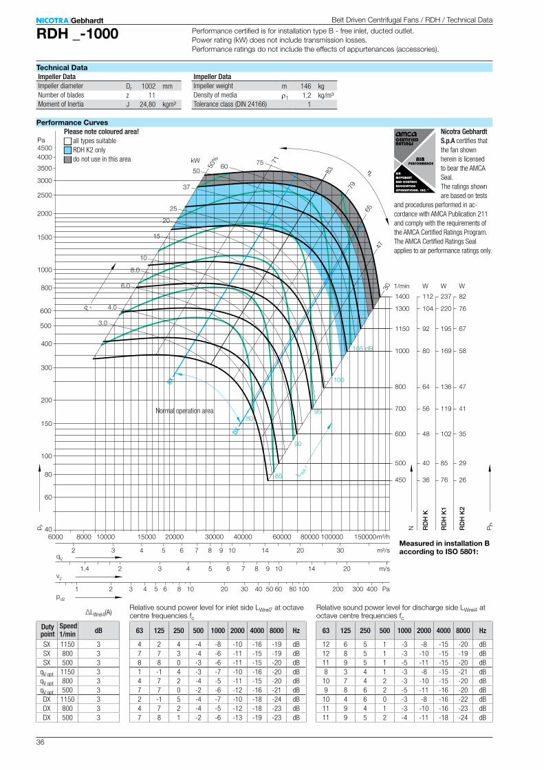
36
RDH _-1000
Dr 1002 mmz 11J 24,80 kgm²
m 146 kgr1 1,2 kg/m³
1
100
150
200
300
400
500
600
800
1000
1500
2000
2500
3000
3500
4000
Pa
40
60
80
6000 8000 10000 15000 20000 30000 40000 60000 80000
4500
100000 150000
450
500
600
700
800
1000
1150
1300
1400
36
40
48
56
64
80
92
104
112
76
85
102
119
136
169
195
220
237
kW
25
3.0
4.0
6.0
8.0
10
15
20
37
5060
65
3047
79
83
71
50%
RD
H K
RD
H K
1
W W1/min
75
3 4 5 6 7 8 92 10 14 20 30
3 4 5 6 7 8 92 10 14 20
3 4 5 6 82 10 30 40 50 60 8020 100 300 400200
m/s
Pa
m³/h
m³/s
85
90
95
100
80
105 dB
1
1.4v2
qV
pd2
p F
N Pb
P r
L WA
7
ηr
SX
DX
26
29
35
41
47
58
67
76
82
RD
H K
2
W
∆LWrel4(A)
63 125 250 500 1000 2000 4000 8000 Hz
4 2 4 -4 -8 -10 -16 -19 dB7 7 3 -4 -6 -11 -15 -19 dB8 8 0 -3 -6 -11 -15 -20 dB1 -1 4 -3 -7 -10 -16 -20 dB4 7 2 -4 -5 -11 -15 -20 dB7 7 0 -2 -6 -12 -16 -21 dB2 -1 5 -4 -7 -10 -18 -24 dB4 7 2 -4 -5 -12 -18 -23 dB7 8 1 -2 -6 -13 -19 -23 dB
63 125 250 500 1000 2000 4000 8000 Hz
12 6 5 1 -3 -8 -15 -20 dB12 8 5 1 -3 -10 -15 -19 dB11 9 5 1 -5 -11 -15 -20 dB8 3 4 1 -3 -8 -15 -21 dB10 7 4 2 -3 -10 -15 -20 dB9 8 6 2 -5 -11 -16 -20 dB10 4 6 0 -3 -8 -16 -22 dB11 9 4 1 -3 -10 -16 -23 dB11 9 5 2 -4 -11 -18 -24 dB
1/min dB
SX 1150 3SX 800 3SX 500 3
qV opt 1150 3qV opt 800 3qV opt 500 3DX 1150 3DX 800 3DX 500 3
Belt Driven Centrifugal Fans / RDH / Technical Data
Technical Data
Performance Curves
Performance certified is for installation type B - free inlet, ducted outlet. Power rating (kW) does not include transmission losses. Performance ratings do not include the effects of appurtenances (accessories).
Measured in installation B according to ISO 5801:
Impeller Data Impeller DataImpeller diameterNumber of bladesMoment of Inertia
Impeller weightDensity of mediaTolerance class (DIN 24166)
Please note coloured area!N all types suitableN RDH K2 onlyN do not use in this area
Relative sound power level for inlet side LWrel7 at octave centre frequencies fc
Normal operation area
Relative sound power level for discharge side LWrel4 at octave centre frequencies fc
Speed Duty point
Nicotra Gebhardt S.p.A certifies that the fan shown herein is licensed to bear the AMCA Seal. The ratings shown are based on tests
and procedures per formed in ac-cordance with AMCA Publication 211 and comply with the requirements of the AMCA Certified Ratings Program. The AMCA Certified Ratings Seal applies to air performance ratings only.

37
RDH _-1000
RDH K-1000 415 kg
700
1267
1544660
18
900
1829
534
1066
130
60h7
13671317 1323
1297
1660
9
1
267
28
1810
900
17 × 22
1267
1451
657
1267
1541
90
90
50
11 6411 64
RDH K1-1000 430 kg
700
1267
1544660
18
900
1829
534
1066
130
60h7
13671317 1323
1297
1660
9
1
267
2818
1090
017 × 22
1267
1451
657
1267
1541
90
90
50
11 64
RDH K2-1000 450 kg
700
1267
1544660
18
900
1829
534
1066
130
60h7
13671317 1323
1297
1700
9
1
267
28
1810
900
17 × 22
1267
1451
657
1267
1541
90
50
90
11 64
Belt Driven Centrifugal Fans / RDH / Technical Data
Dimensions in mm, subject to change.
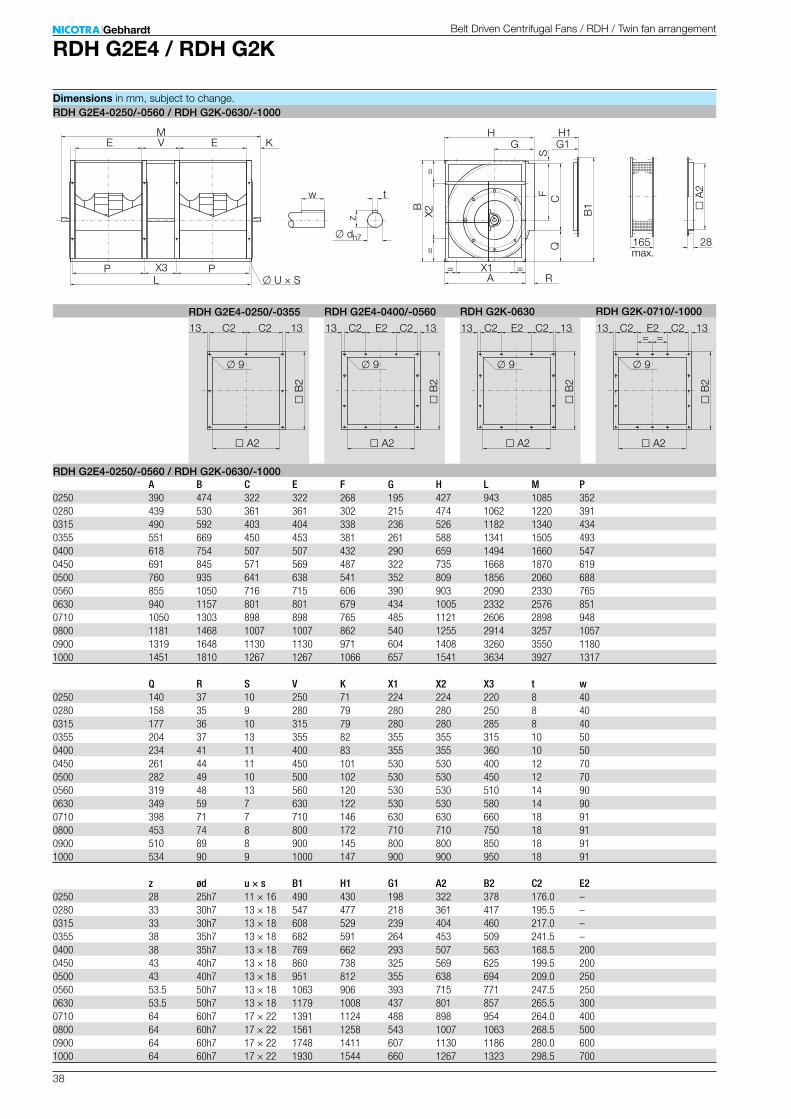
38
RDH G2E4 / RDH G2K
H1G1
B
X1
X2 B1
QF
165 max.
LP
M
A
2
28
U × S A
G
C
EH
S
K
RP
E V
X3
t
dh7
B
2
A2
C2
9
13
w
z 9
E213C2
B
2 A2
C213 13C2
==
= =
RDH G2E4-0250/-0560 / RDH G2K-0630/-1000
RDH G2E4-0250/-0355 RDH G2E4-0400/-0560
RDH G2E4-0250/-0560 / RDH G2K-0630/-1000 A B C E F G H L M P0250 390 474 322 322 268 195 427 943 1085 3520280 439 530 361 361 302 215 474 1062 1220 3910315 490 592 403 404 338 236 526 1182 1340 4340355 551 669 450 453 381 261 588 1341 1505 4930400 618 754 507 507 432 290 659 1494 1660 5470450 691 845 571 569 487 322 735 1668 1870 6190500 760 935 641 638 541 352 809 1856 2060 6880560 855 1050 716 715 606 390 903 2090 2330 7650630 940 1157 801 801 679 434 1005 2332 2576 8510710 1050 1303 898 898 765 485 1121 2606 2898 9480800 1181 1468 1007 1007 862 540 1255 2914 3257 10570900 1319 1648 1130 1130 971 604 1408 3260 3550 11801000 1451 1810 1267 1267 1066 657 1541 3634 3927 1317
Q R S V K X1 X2 X3 t w0250 140 37 10 250 71 224 224 220 8 400280 158 35 9 280 79 280 280 250 8 400315 177 36 10 315 79 280 280 285 8 400355 204 37 13 355 82 355 355 315 10 500400 234 41 11 400 83 355 355 360 10 500450 261 44 11 450 101 530 530 400 12 700500 282 49 10 500 102 530 530 450 12 700560 319 48 13 560 120 530 530 510 14 900630 349 59 7 630 122 530 530 580 14 900710 398 71 7 710 146 630 630 660 18 910800 453 74 8 800 172 710 710 750 18 910900 510 89 8 900 145 800 800 850 18 911000 534 90 9 1000 147 900 900 950 18 91
z ød u × s B1 H1 G1 A2 B2 C2 E20250 28 25h7 11 × 16 490 430 198 322 378 176.0 –0280 33 30h7 13 × 18 547 477 218 361 417 195.5 –0315 33 30h7 13 × 18 608 529 239 404 460 217.0 –0355 38 35h7 13 × 18 682 591 264 453 509 241.5 –0400 38 35h7 13 × 18 769 662 293 507 563 168.5 2000450 43 40h7 13 × 18 860 738 325 569 625 199.5 2000500 43 40h7 13 × 18 951 812 355 638 694 209.0 2500560 53.5 50h7 13 × 18 1063 906 393 715 771 247.5 2500630 53.5 50h7 13 × 18 1179 1008 437 801 857 265.5 3000710 64 60h7 17 × 22 1391 1124 488 898 954 264.0 4000800 64 60h7 17 × 22 1561 1258 543 1007 1063 268.5 5000900 64 60h7 17 × 22 1748 1411 607 1130 1186 280.0 6001000 64 60h7 17 × 22 1930 1544 660 1267 1323 298.5 700
RDH G2K-0630 RDH G2K-0710/-1000
9
E2
B
2
A2
C213 13C2
9
E2
B
2
A2
C213 13C2= =
Belt Driven Centrifugal Fans / RDH / Twin fan arrangement
Dimensions in mm, subject to change.
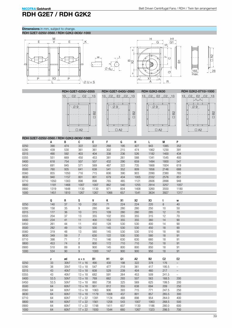
39
RDH G2E7 / RDH G2K2
H1G1
t
B
X1
X2 B1
QF
165 max.
dh7
LP
B
2
A2
C2
M
9
A
2
28
U × S A
G
C
EH
13
S
K
RP
E V
X3
w
z 9
E213C2
B
2 A2
C213 13C2
==
= =
RDH G2E7-0250/-0560 / RDH G2K2-0630/-1000
RDH G2E7-0250/-0355 RDH G2E7-0400/-0560
RDH G2E7-0250/-0560 / RDH G2K2-0630/-1000 A B C E F G H L M P0250 390 474 322 322 268 195 427 943 1085 3520280 439 530 361 361 302 215 474 1062 1230 3910315 490 592 403 404 338 236 526 1182 1400 4340355 551 669 450 453 381 261 588 1341 1545 4930400 618 754 507 507 432 290 659 1494 1800 5470450 691 845 571 569 487 322 735 1668 1924 6190500 760 935 641 638 541 352 809 1856 2146 6880560 855 1050 716 715 606 390 903 2090 2380 7650630 940 1157 801 801 679 434 1005 2332 2576 8510710 1050 1303 898 898 765 485 1121 2606 2898 9480800 1181 1468 1007 1007 862 540 1255 2914 3257 10570900 1319 1648 1130 1130 971 604 1408 3260 3550 11801000 1451 1810 1267 1267 1066 657 1541 3634 3927 1317
Q R S V K X1 X2 X3 t w0250 140 37 10 250 71 224 224 220 8 400280 158 35 9 280 84 280 280 250 10 500315 177 36 10 315 109 280 280 285 12 700355 204 37 13 355 102 355 355 315 12 700400 234 41 11 400 153 355 355 360 14 900450 261 44 11 450 128 530 530 400 14 900500 282 49 10 500 145 530 530 450 18 900560 319 48 13 560 145 530 530 510 18 900630 349 59 7 630 122 530 530 580 18 910710 398 71 7 710 146 630 630 660 18 910800 453 74 8 800 172 710 710 750 18 910900 510 89 8 900 145 800 800 850 18 911000 534 90 9 1000 147 900 900 950 18 91
z ød u × s B1 H1 G1 A2 B2 C2 E20250 33 30h7 11 × 16 490 430 198 322 378 176 –0280 38 35h7 13 × 18 547 477 218 361 417 195.5 –0315 43 40h7 13 × 18 608 529 239 404 460 217 –0355 43 40h7 13 × 18 682 591 264 453 509 241.5 –0400 53.5 50h7 13 × 18 769 662 293 507 563 168.5 2000450 53.5 50h7 13 × 18 860 738 325 569 625 199.5 2000500 64 60h7 13 × 18 951 812 355 638 694 209 2500560 64 60h7 13 × 18 1063 906 393 715 771 247.5 2500630 64 60h7 13 × 18 1179 1008 437 801 857 265.5 3000710 64 60h7 17 × 22 1391 1124 488 898 954 264.0 4000800 64 60h7 17 × 22 1561 1258 543 1007 1063 268.5 5000900 64 60h7 17 × 22 1748 1411 607 1130 1186 280.0 6001000 64 60h7 17 × 22 1930 1544 660 1267 1323 298.5 700
RDH G2K2-0630 RDH G2K2-0710/-1000
9
E2
B
2
A2
C213 13C2
9
E2
B
2
A2
C213 13C2= =
Belt Driven Centrifugal Fans / RDH / Twin fan arrangement
Dimensions in mm, subject to change.
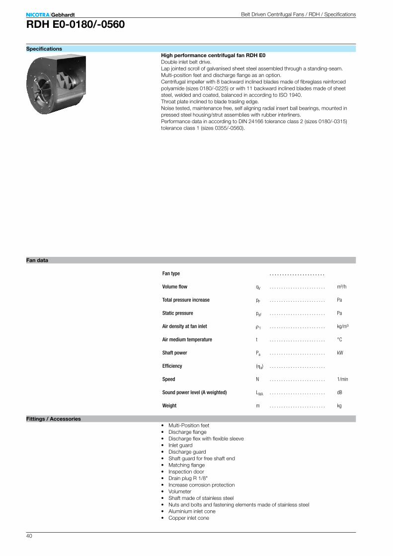
40
RDH E0-0180/-0560
. . . . . . . . . . . . . . . . . . . . . .
qV . . . . . . . . . . . . . . . . . . . . . . . . m³/h
pF . . . . . . . . . . . . . . . . . . . . . . . . Pa
psF . . . . . . . . . . . . . . . . . . . . . . . . Pa
r1 . . . . . . . . . . . . . . . . . . . . . . . . kg/m³
t . . . . . . . . . . . . . . . . . . . . . . . . °C
Pa . . . . . . . . . . . . . . . . . . . . . . . . kW
(ha) . . . . . . . . . . . . . . . . . . . . . . . .
N . . . . . . . . . . . . . . . . . . . . . . . . 1/min
LWA . . . . . . . . . . . . . . . . . . . . . . . . dB
m . . . . . . . . . . . . . . . . . . . . . . . . kg
Belt Driven Centrifugal Fans / RDH / Specifications
Specifications
Fan data
Fittings / Accessories
High performance centrifugal fan RDH E0Double inlet belt drive. Lap jointed scroll of galvanised sheet steel assembled through a standing-seam. Multi-position feet and discharge flange as an option. Centrifugal impeller with 8 backward inclined blades made of fibreglass reinforced polyamide (sizes 0180/-0225) or with 11 backward inclined blades made of sheet steel, welded and coated, balanced in according to ISO 1940. Throat plate inclined to blade trasling edge. Noise tested, maintenance free, self aligning radial insert ball bearings, mounted in pressed steel housing/strut assemblies with rubber interliners. Performance data in according to DIN 24166 tolerance class 2 (sizes 0180/-0315) tolerance class 1 (sizes 0355/-0560).
• Multi-Position feet• Discharge flange• Discharge flex with flexible sleeve• Inlet guard• Discharge guard• Shaft guard for free shaft end• Matching flange• Inspection door• Drain plug R 1/8"• Increase corrosion protection• Volumeter• Shaft made of stainless steel• Nuts and bolts and fastening elements made of stainless steel• Aluminium inlet cone• Copper inlet cone
Fan type
Volume flow
Total pressure increase
Static pressure
Air density at fan inlet
Air medium temperature
Shaft power
Efficiency
Speed
Sound power level (A weighted)
Weight
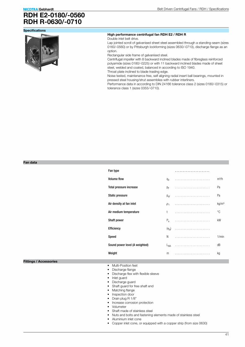
41
RDH E2-0180/-0560RDH R-0630/-0710
. . . . . . . . . . . . . . . . . . . . . .
qV . . . . . . . . . . . . . . . . . . . . . . . . m³/h
pF . . . . . . . . . . . . . . . . . . . . . . . . Pa
psF . . . . . . . . . . . . . . . . . . . . . . . . Pa
r1 . . . . . . . . . . . . . . . . . . . . . . . . kg/m³
t . . . . . . . . . . . . . . . . . . . . . . . . °C
Pa . . . . . . . . . . . . . . . . . . . . . . . . kW
(ha) . . . . . . . . . . . . . . . . . . . . . . . .
N . . . . . . . . . . . . . . . . . . . . . . . . 1/min
LWA . . . . . . . . . . . . . . . . . . . . . . . . dB
m . . . . . . . . . . . . . . . . . . . . . . . . kg
Belt Driven Centrifugal Fans / RDH / Specifications
Specifications
Fan data
Fittings / Accessories
High performance centrifugal fan RDH E2 / RDH RDouble inlet belt drive. Lap jointed scroll of galvanised sheet steel assembled through a standing-seam (sizes 0160/-0560) or by Pittsburgh lockforming (sizes 0630/-0710), discharge flange as an option. Rectangular side frame of galvanised steel. Centrifugal impeller with 8 backward inclined blades made of fibreglass reinforced polyamide (sizes 0180/-0225) or with 11 backward inclined blades made of sheet steel, welded and coated, balanced in according to ISO 1940. Throat plate inclined to blade trasling edge. Noise tested, maintenance free, self aligning radial insert ball bearings, mounted in pressed steel housing/strut assemblies with rubber interliners. Performance data in according to DIN 24166 tolerance class 2 (sizes 0180/-0315) or tolerance class 1 (sizes 0355/-0710).
• Multi-Position feet• Discharge flange• Discharge flex with flexible sleeve• Inlet guard• Discharge guard• Shaft guard for free shaft end• Matching flange• Inspection door• Drain plug R 1/8"• Increase corrosion protection• Volumeter• Shaft made of stainless steel• Nuts and bolts and fastening elements made of stainless steel• Aluminium inlet cone• Copper inlet cone, or equipped with a copper strip (from size 0630)
Fan type
Volume flow
Total pressure increase
Static pressure
Air density at fan inlet
Air medium temperature
Shaft power
Efficiency
Speed
Sound power level (A weighted)
Weight
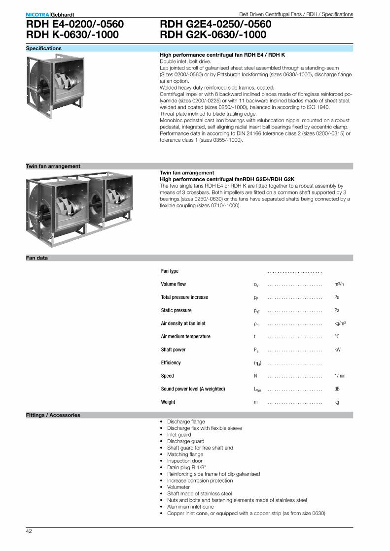
42
RDH G2E4-0250/-0560RDH G2K-0630/-1000
RDH E4-0200/-0560RDH K-0630/-1000
. . . . . . . . . . . . . . . . . . . . . .
qV . . . . . . . . . . . . . . . . . . . . . . . . m³/h
pF . . . . . . . . . . . . . . . . . . . . . . . . Pa
psF . . . . . . . . . . . . . . . . . . . . . . . . Pa
r1 . . . . . . . . . . . . . . . . . . . . . . . . kg/m³
t . . . . . . . . . . . . . . . . . . . . . . . . °C
Pa . . . . . . . . . . . . . . . . . . . . . . . . kW
(ha) . . . . . . . . . . . . . . . . . . . . . . . .
N . . . . . . . . . . . . . . . . . . . . . . . . 1/min
LWA . . . . . . . . . . . . . . . . . . . . . . . . dB
m . . . . . . . . . . . . . . . . . . . . . . . . kg
Specifications
Fan data
Fittings / Accessories• Discharge flange• Discharge flex with flexible sleeve• Inlet guard• Discharge guard• Shaft guard for free shaft end• Matching flange• Inspection door• Drain plug R 1/8"• Reinforcing side frame hot dip galvanised• Increase corrosion protection• Volumeter• Shaft made of stainless steel• Nuts and bolts and fastening elements made of stainless steel• Aluminium inlet cone• Copper inlet cone, or equipped with a copper strip (as from size 0630)
High performance centrifugal fan RDH E4 / RDH KDouble inlet, belt drive. Lap jointed scroll of galvanised sheet steel assembled through a standing-seam (Sizes 0200/-0560) or by Pittsburgh lockforming (sizes 0630/-1000), discharge flange as an option. Welded heavy duty reinforced side frames, coated. Centrifugal impeller with 8 backward inclined blades made of fibreglass reinforced po-lyamide (sizes 0200/-0225) or with 11 backward inclined blades made of sheet steel, welded and coated (sizes 0250/-1000), balanced in according to ISO 1940. Throat plate inclined to blade trasling edge. Monobloc pedestal cast iron bearings with relubrication nipple, mounted on a robust pedestal, integrated, self aligning radial insert ball bearings fixed by eccentric clamp. Performance data in according to DIN 24166 tolerance class 2 (sizes 0200/-0315) or tolerance class 1 (sizes 0355/-1000).
Belt Driven Centrifugal Fans / RDH / Specifications
Fan type
Volume flow
Total pressure increase
Static pressure
Air density at fan inlet
Air medium temperature
Shaft power
Efficiency
Speed
Sound power level (A weighted)
Weight
Twin fan arrangementTwin fan arrangement High performance centrifugal fanRDH G2E4/RDH G2KThe two single fans RDH E4 or RDH K are fitted together to a robust assembly by means of 3 crossbars. Both impellers are fitted on a common shaft supported by 3 bearings.(sizes 0250/-0630) or the fans have separated shafts being connected by a flexible coupling (sizes 0710/-1000).

43
RDH E6-0315/-0560RDH K1-0630/-0900
. . . . . . . . . . . . . . . . . . . . . .
qV . . . . . . . . . . . . . . . . . . . . . . . . m³/h
pF . . . . . . . . . . . . . . . . . . . . . . . . Pa
psF . . . . . . . . . . . . . . . . . . . . . . . . Pa
r1 . . . . . . . . . . . . . . . . . . . . . . . . kg/m³
t . . . . . . . . . . . . . . . . . . . . . . . . °C
Pa . . . . . . . . . . . . . . . . . . . . . . . . kW
(ha) . . . . . . . . . . . . . . . . . . . . . . . .
N . . . . . . . . . . . . . . . . . . . . . . . . 1/min
LWA . . . . . . . . . . . . . . . . . . . . . . . . dB
m . . . . . . . . . . . . . . . . . . . . . . . . kg
Specifications
Fan data
Fittings / Accessories• Discharge flange• Discharge flex with flexible sleeve• Inlet guard• Discharge guard• Shaft guard for free shaft end• Matching flange• Inspection door• Drain plug R 1/8"• Reinforcing side frame hot dip galvanised• Increase corrosion protection• Volumeter• Shaft made of stainless steel• Nuts and bolts and fastening elements made of stainless steel• Aluminium inlet cone• Copper inlet cone, or equipped with a copper strip (from size 0630)
High performance centrifugal fan RDH E6 / RDH K1Double inlet, belt drive. Lap jointed scroll of galvanised sheet steel assembled through a standing-seam or by Pittsburgh lockforming (sizes 0630/-1000), discharge flange as an option. Welded heavy duty reinforced side frames, coated. Centrifugal impeller with 11 backward inclined blades made of sheet steel, welded and coated, balanced in according to ISO 1940. Throat plate inclined to blade trasling edge. Monobloc pedestal cast iron bearings with relubrication nipple, mounted on a robust pedestal, integrated, self aligning radial insert ball bearings fixed by conical sleeve. Performance data in according to DIN 24166 tolerance class 2 (size 0315) or toleran-ce class 1 (sizes 0355/-1000).
Belt Driven Centrifugal Fans / RDH / Specifications
Fan type
Volume flow
Total pressure increase
Static pressure
Air density at fan inlet
Air medium temperature
Shaft power
Efficiency
Speed
Sound power level (A weighted)
Weight
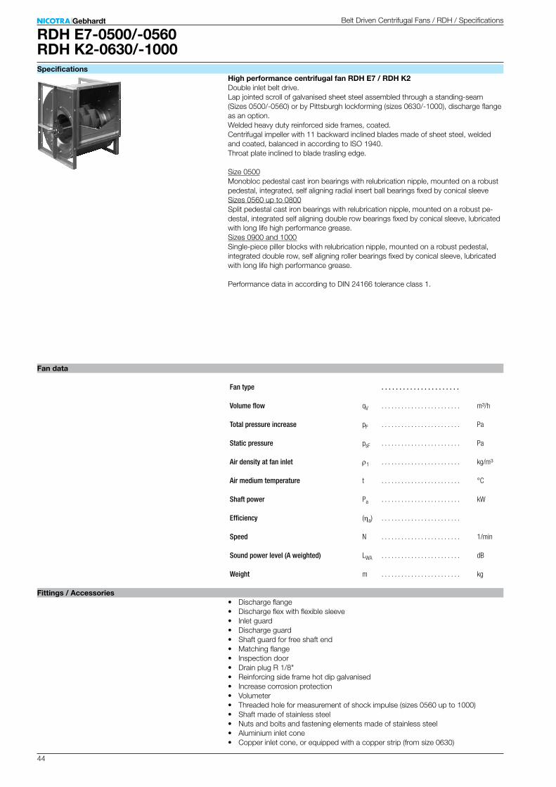
44
RDH E7-0500/-0560RDH K2-0630/-1000
. . . . . . . . . . . . . . . . . . . . . .
qV . . . . . . . . . . . . . . . . . . . . . . . . m³/h
pF . . . . . . . . . . . . . . . . . . . . . . . . Pa
psF . . . . . . . . . . . . . . . . . . . . . . . . Pa
r1 . . . . . . . . . . . . . . . . . . . . . . . . kg/m³
t . . . . . . . . . . . . . . . . . . . . . . . . °C
Pa . . . . . . . . . . . . . . . . . . . . . . . . kW
(ha) . . . . . . . . . . . . . . . . . . . . . . . .
N . . . . . . . . . . . . . . . . . . . . . . . . 1/min
LWA . . . . . . . . . . . . . . . . . . . . . . . . dB
m . . . . . . . . . . . . . . . . . . . . . . . . kg
Specifications
Fan data
Fittings / Accessories• Discharge flange• Discharge flex with flexible sleeve• Inlet guard• Discharge guard• Shaft guard for free shaft end• Matching flange• Inspection door• Drain plug R 1/8"• Reinforcing side frame hot dip galvanised• Increase corrosion protection• Volumeter• Threaded hole for measurement of shock impulse (sizes 0560 up to 1000)• Shaft made of stainless steel• Nuts and bolts and fastening elements made of stainless steel• Aluminium inlet cone• Copper inlet cone, or equipped with a copper strip (from size 0630)
High performance centrifugal fan RDH E7 / RDH K2Double inlet belt drive. Lap jointed scroll of galvanised sheet steel assembled through a standing-seam (Sizes 0500/-0560) or by Pittsburgh lockforming (sizes 0630/-1000), discharge flange as an option. Welded heavy duty reinforced side frames, coated. Centrifugal impeller with 11 backward inclined blades made of sheet steel, welded and coated, balanced in according to ISO 1940. Throat plate inclined to blade trasling edge.
Size 0500Monobloc pedestal cast iron bearings with relubrication nipple, mounted on a robust pedestal, integrated, self aligning radial insert ball bearings fixed by conical sleeveSizes 0560 up to 0800Split pedestal cast iron bearings with relubrication nipple, mounted on a robust pe-destal, integrated self aligning double row bearings fixed by conical sleeve, lubricated with long life high performance grease.Sizes 0900 and 1000Single-piece piller blocks with relubrication nipple, mounted on a robust pedestal, integrated double row, self aligning roller bearings fixed by conical sleeve, lubricated with long life high performance grease. Performance data in according to DIN 24166 tolerance class 1.
Belt Driven Centrifugal Fans / RDH / Specifications
Fan type
Volume flow
Total pressure increase
Static pressure
Air density at fan inlet
Air medium temperature
Shaft power
Efficiency
Speed
Sound power level (A weighted)
Weight
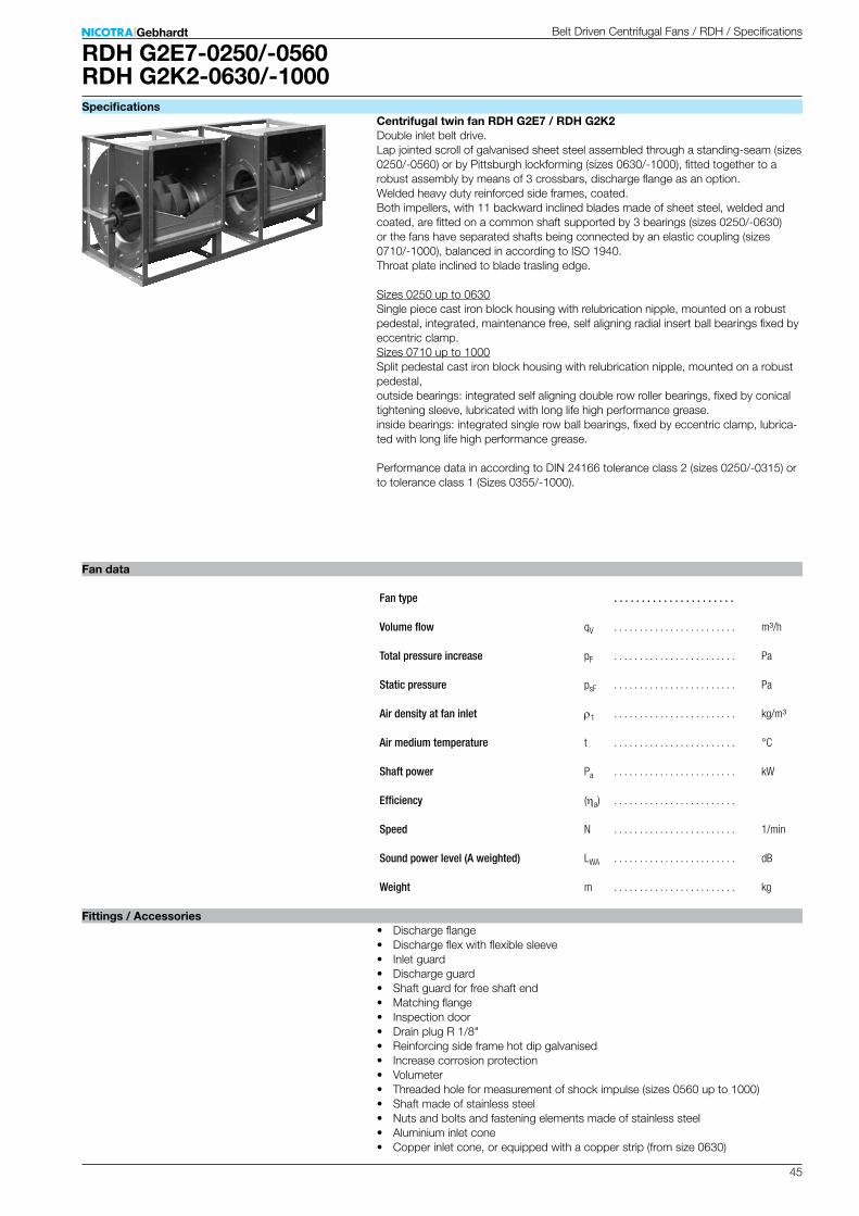
45
RDH G2E7-0250/-0560RDH G2K2-0630/-1000
. . . . . . . . . . . . . . . . . . . . . .
qV . . . . . . . . . . . . . . . . . . . . . . . . m³/h
pF . . . . . . . . . . . . . . . . . . . . . . . . Pa
psF . . . . . . . . . . . . . . . . . . . . . . . . Pa
r1 . . . . . . . . . . . . . . . . . . . . . . . . kg/m³
t . . . . . . . . . . . . . . . . . . . . . . . . °C
Pa . . . . . . . . . . . . . . . . . . . . . . . . kW
(ha) . . . . . . . . . . . . . . . . . . . . . . . .
N . . . . . . . . . . . . . . . . . . . . . . . . 1/min
LWA . . . . . . . . . . . . . . . . . . . . . . . . dB
m . . . . . . . . . . . . . . . . . . . . . . . . kg
Specifications
Fan data
Fittings / Accessories• Discharge flange• Discharge flex with flexible sleeve• Inlet guard• Discharge guard• Shaft guard for free shaft end• Matching flange• Inspection door• Drain plug R 1/8"• Reinforcing side frame hot dip galvanised• Increase corrosion protection• Volumeter• Threaded hole for measurement of shock impulse (sizes 0560 up to 1000)• Shaft made of stainless steel• Nuts and bolts and fastening elements made of stainless steel• Aluminium inlet cone• Copper inlet cone, or equipped with a copper strip (from size 0630)
Centrifugal twin fan RDH G2E7 / RDH G2K2Double inlet belt drive. Lap jointed scroll of galvanised sheet steel assembled through a standing-seam (sizes 0250/-0560) or by Pittsburgh lockforming (sizes 0630/-1000), fitted together to a robust assembly by means of 3 crossbars, discharge flange as an option. Welded heavy duty reinforced side frames, coated. Both impellers, with 11 backward inclined blades made of sheet steel, welded and coated, are fitted on a common shaft supported by 3 bearings (sizes 0250/-0630) or the fans have separated shafts being connected by an elastic coupling (sizes 0710/-1000), balanced in according to ISO 1940. Throat plate inclined to blade trasling edge.
Sizes 0250 up to 0630Single piece cast iron block housing with relubrication nipple, mounted on a robust pedestal, integrated, maintenance free, self aligning radial insert ball bearings fixed by eccentric clamp.Sizes 0710 up to 1000Split pedestal cast iron block housing with relubrication nipple, mounted on a robust pedestal, outside bearings: integrated self aligning double row roller bearings, fixed by conical tightening sleeve, lubricated with long life high performance grease. inside bearings: integrated single row ball bearings, fixed by eccentric clamp, lubrica-ted with long life high performance grease. Performance data in according to DIN 24166 tolerance class 2 (sizes 0250/-0315) or to tolerance class 1 (Sizes 0355/-1000).
Fan type
Volume flow
Total pressure increase
Static pressure
Air density at fan inlet
Air medium temperature
Shaft power
Efficiency
Speed
Sound power level (A weighted)
Weight
Belt Driven Centrifugal Fans / RDH / Specifications

46
Fittings / Accessories
[1] Mounting feet[2] Discharge flange[3] Discharge flex[4] Inlet guard[5] Discharge guard[6] Shaft guard[7] Mounting flange[8] Inspection door[9] Drain plugA extended corrosion protectionA ATEX-Execution (RZR)A Impellerblades continuosly welded (RZR)A Casing continuosly welden-inside (RZR)A Casing continuosly welden- inside/outside (RZR)A Split casing (RZR 13/19)A Shaft from stainless steelA Nuts and bolts from stainless steelA Thread for impuls sensor fittingA Volumeter (RDH / RZR)A Copper inlet coneA Aluminium inlet cone (ADH / AT / RDH)A hot dip galvanised side frame (ADH / RDH)A relubricatable bearings (relubrication during operation, RZR)
Fan set (ADH / AT / RDH on request)[10] Base frame[11] Pick-a-Back[12] Belt drive[13] Drive guardA Belt guard split horizontallyA Access door on belt guardA Opening on belt guard for speed measuring device[14] Drive motor[15] Anti-vibration mounts

47
Gebhardt fan systems – the "completely carefree" package for installation fans with belt drive
Fan systems with components tailored for each other, precisely assembled and adjusted, individually tested, delivered quickly and on time, allow for problem-free processing and ensure long and reliable operation.
Size has its price so we build as small as possible
A Optimised base frame lengths, tailored to the casing position and motor size and small system construction heights save valuable space in the air conditioning unit
A Various casing and drive positions allow for individual adjustment to the most diverse applications
A Optimised flat belt drives allow for efficient operation with a high level of convenience
Where required, we deliver our fan systems with safety equipment complying with DIN EN ISO 13857 for safe operation!
e.g. Belt guardA also as segmented designA also with inspection holeA also with rotation speed measurement opening.
Fan set diversity
Version
Pick-A-Back
Description Figure
Pick-A-Back
Compact base frame
Base Frame, CC-profile
Base Frame, U-profile
for sizes 0200/-0355
for sizes 0400/-1000
Integrated compact base frame for sizes up to 0500.
Base frames made from CC-profiles with length optimation.
Heavy duty base frame made from U-profiles, welded and painted, from size 0800 upward.
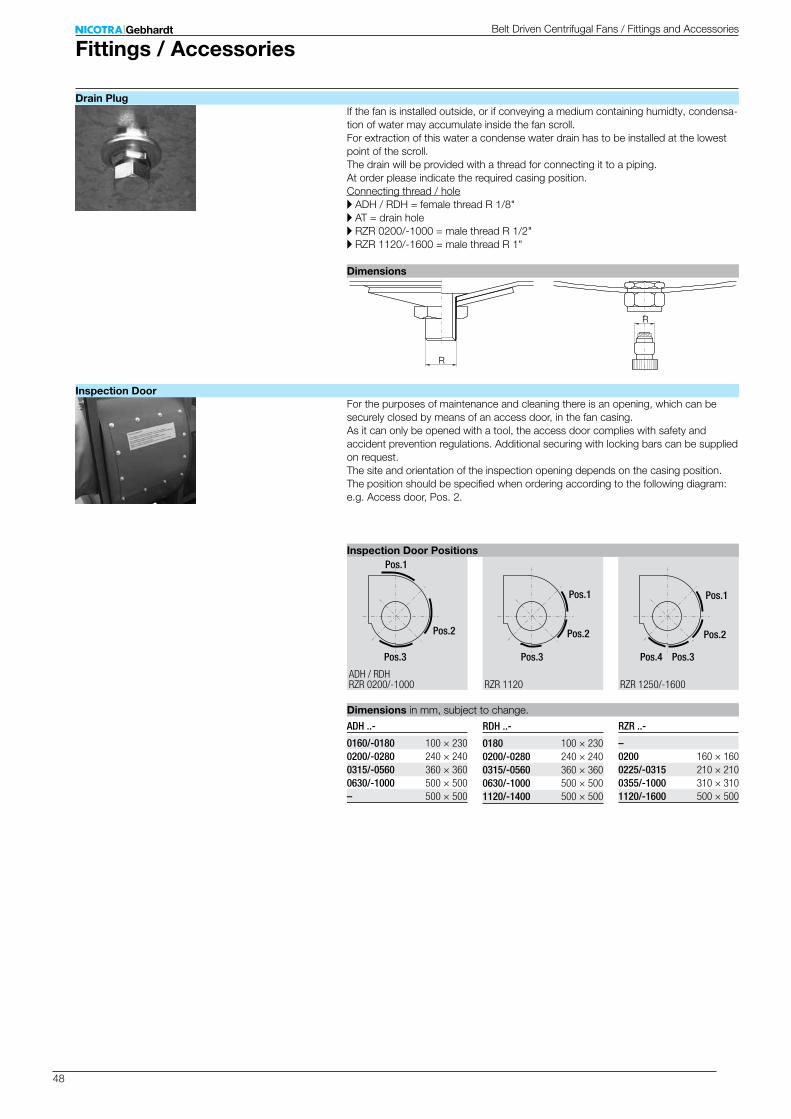
48
R
R
Pos.1
Pos.3
Pos.2
Pos.1
Pos.3
Pos.2
Pos.4
Pos.1
Pos.3
Pos.2
RZR 1120 RZR 1250/-1600RZR 0200/-1000ADH / RDH
ADH ..-
0160/-0180 100 × 2300200/-0280 240 × 2400315/-0560 360 × 3600630/-1000 500 × 500– 500 × 500
RDH ..-
0180 100 × 2300200/-0280 240 × 2400315/-0560 360 × 3600630/-1000 500 × 5001120/-1400 500 × 500
RZR ..-
– 0200 160 × 1600225/-0315 210 × 2100355/-1000 310 × 3101120/-1600 500 × 500
Fittings / AccessoriesBelt Driven Centrifugal Fans / Fittings and Accessories
If the fan is installed outside, or if conveying a medium containing humidty, condensa-tion of water may accumulate inside the fan scroll. For extraction of this water a condense water drain has to be installed at the lowest point of the scroll. The drain will be provided with a thread for connecting it to a piping. At order please indicate the required casing position.Connecting thread / holeA ADH / RDH = female thread R 1/8"A AT = drain holeA RZR 0200/-1000 = male thread R 1/2"A RZR 1120/-1600 = male thread R 1"
For the purposes of maintenance and cleaning there is an opening, which can be securely closed by means of an access door, in the fan casing. As it can only be opened with a tool, the access door complies with safety and accident prevention regulations. Additional securing with locking bars can be supplied on request. The site and orientation of the inspection opening depends on the casing position. The position should be specified when ordering according to the following diagram: e.g. Access door, Pos. 2.
Drain Plug
Inspection Door
Inspection Door Positions
Dimensions in mm, subject to change.
Dimensions
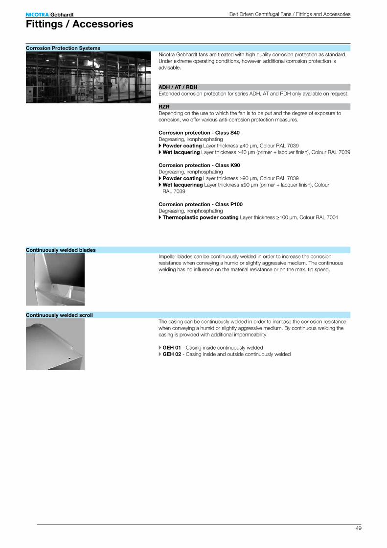
49
RZR
ADH / AT / RDH
Fittings / AccessoriesBelt Driven Centrifugal Fans / Fittings and Accessories
Nicotra Gebhardt fans are treated with high quality corrosion protection as standard. Under extreme operating conditions, however, additional corrosion protection is advisable.
Depending on the use to which the fan is to be put and the degree of exposure to corrosion, we offer various anti-corrosion protection measures.
Corrosion protection - Class S40Degreasing, ironphosphatingA Powder coating Layer thickness ≥40 μm, Colour RAL 7039A Wet lacquering Layer thickness ≥40 μm (primer + lacquer finish), Colour RAL 7039
Corrosion protection - Class K90Degreasing, ironphosphatingA Powder coating Layer thickness ≥90 μm, Colour RAL 7039A Wet lacquerinag Layer thickness ≥90 μm (primer + lacquer finish), Colour
RAL 7039
Corrosion protection - Class P100Degreasing, ironphosphatingA Thermoplastic powder coating Layer thickness ≥100 μm, Colour RAL 7001
Extended corrosion protection for series ADH, AT and RDH only available on request.
Impeller blades can be continuously welded in order to increase the corrosion resistance when conveying a humid or slightly aggressive medium. The continuous welding has no influence on the material resistance or on the max. tip speed.
The casing can be continuously welded in order to increase the corrosion resistance when conveying a humid or slightly aggressive medium. By continuous welding the casing is provided with additional impermeability.
A GEH 01 - Casing inside continuously weldedA GEH 02 - Casing inside and outside continuously welded
Corrosion Protection Systems
Continuously welded blades
Continuously welded scroll
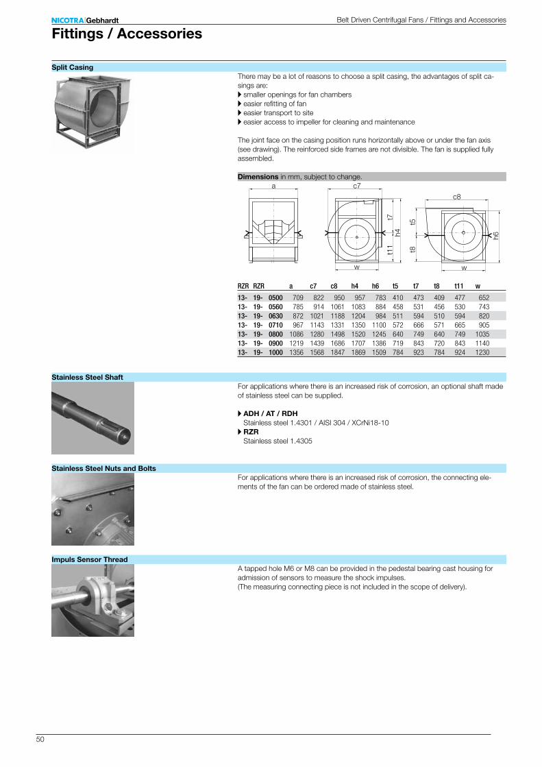
50
w
t7t1
1 t8
h6
t5
h4
w
c7
c8
a
RZR RZR a c7 c8 h4 h6 t5 t7 t8 t11 w
13- 19- 0500 709 822 950 957 783 410 473 409 477 65213- 19- 0560 785 914 1061 1083 884 458 531 456 530 74313- 19- 0630 872 1021 1188 1204 984 511 594 510 594 82013- 19- 0710 967 1143 1331 1350 1100 572 666 571 665 90513- 19- 0800 1086 1280 1498 1520 1245 640 749 640 749 103513- 19- 0900 1219 1439 1686 1707 1386 719 843 720 843 114013- 19- 1000 1356 1568 1847 1869 1509 784 923 784 924 1230
There may be a lot of reasons to choose a split casing, the advantages of split ca-sings are:A smaller openings for fan chambersA easier refitting of fanA easier transport to siteA easier access to impeller for cleaning and maintenance
The joint face on the casing position runs horizontally above or under the fan axis (see drawing). The reinforced side frames are not divisible. The fan is supplied fully assembled.
For applications where there is an increased risk of corrosion, an optional shaft made of stainless steel can be supplied.
A ADH / AT / RDH Stainless steel 1.4301 / AISI 304 / XCrNi18-10
A RZR Stainless steel 1.4305
For applications where there is an increased risk of corrosion, the connecting ele-ments of the fan can be ordered made of stainless steel.
A tapped hole M6 or M8 can be provided in the pedestal bearing cast housing for admission of sensors to measure the shock impulses. (The measuring connecting piece is not included in the scope of delivery).
Fittings / AccessoriesBelt Driven Centrifugal Fans / Fittings and Accessories
Split Casing
Dimensions in mm, subject to change.
Stainless Steel Shaft
Stainless Steel Nuts and Bolts
Impuls Sensor Thread
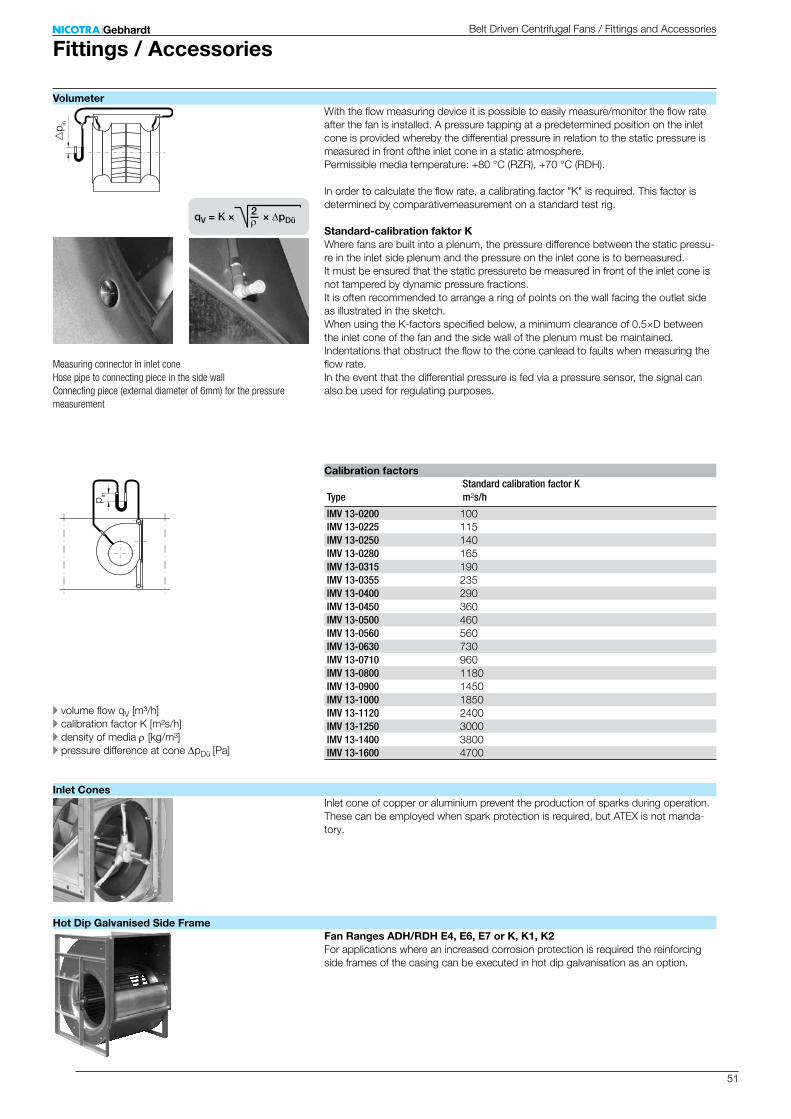
51
p in
p in
IMV 13-0200 100IMV 13-0225 115IMV 13-0250 140IMV 13-0280 165IMV 13-0315 190IMV 13-0355 235IMV 13-0400 290IMV 13-0450 360IMV 13-0500 460IMV 13-0560 560IMV 13-0630 730IMV 13-0710 960IMV 13-0800 1180IMV 13-0900 1450IMV 13-1000 1850IMV 13-1120 2400IMV 13-1250 3000IMV 13-1400 3800IMV 13-1600 4700
qV = K × — × pDü2
With the flow measuring device it is possible to easily measure/monitor the flow rate after the fan is installed. A pressure tapping at a predetermined position on the inlet cone is provided whereby the differential pressure in relation to the static pressure is measured in front ofthe inlet cone in a static atmosphere. Permissible media temperature: +80 °C (RZR), +70 °C (RDH). In order to calculate the flow rate, a calibrating factor "K" is required. This factor is determined by comparativemeasurement on a standard test rig.
Standard-calibration faktor KWhere fans are built into a plenum, the pressure difference between the static pressu-re in the inlet side plenum and the pressure on the inlet cone is to bemeasured. It must be ensured that the static pressureto be measured in front of the inlet cone is not tampered by dynamic pressure fractions. It is often recommended to arrange a ring of points on the wall facing the outlet side as illustrated in the sketch. When using the K-factors specified below, a minimum clearance of 0.5×D between the inlet cone of the fan and the side wall of the plenum must be maintained. Indentations that obstruct the flow to the cone canlead to faults when measuring the flow rate. In the event that the differential pressure is fed via a pressure sensor, the signal can also be used for regulating purposes.
Type
Standard calibration factor K m²s/h
Inlet cone of copper or aluminium prevent the production of sparks during operation. These can be employed when spark protection is required, but ATEX is not manda-tory.
Fan Ranges ADH/RDH E4, E6, E7 or K, K1, K2For applications where an increased corrosion protection is required the reinforcing side frames of the casing can be executed in hot dip galvanisation as an option.
Fittings / AccessoriesBelt Driven Centrifugal Fans / Fittings and Accessories
Volumeter
Calibration factors
Inlet Cones
Hot Dip Galvanised Side Frame
A volume flow qV [m³/h]A calibration factor K [m²s/h]A density of media r [kg/m³]A pressure difference at cone DpDü [Pa]
Measuring connector in inlet coneHose pipe to connecting piece in the side wallConnecting piece (external diameter of 6mm) for the pressure measurement

52
ADH / AT / RDH RZR
Series RZRThe lubrication unit IWN allows the fan bearings to be greased even when in operati-on. The lubrication tubes screwed into the bearing housing are lead out and fastened at the side wall of the fan. If desired, the lubrication tubes can be lead to the drive side of the fan.A IWN 01 - uses standard greaseA IWN 11 - uses moisture resistant grease
For more details see "Technical Description" - "Bearings"!
Series ADH / RDHThe bearing housings of the fan ranges ADH / RDH E4, E6, E7 or K, K1, K2 and AT AR, TIC are equipped with directly fitted grease nipples.
Feet made from galvanized steel, either mounted or loose, enable the fan to be ins-talled with a 0, 90 and 270 orientation.
The fans are designed for installation in equipment and as standard are not equipped with protective guards.They should not be put into operation before all protective devices are fitted and connected!Protective measures must be carried out as set out in DIN EN ISO 12100 "Safety of machinery - Basic concepts, general principles for design". If the application of the fan allows free access to the inlet and discharge apertures, safety devices must be put in place on the fan in accordance with DIN EN ISO 13857! Suitable safety guards are available as an optional extra.
Contact guard for the free end of the shaft for double inlet centrifugal fans. Models in accordance with DIN EN ISO 13857, made of painted steel mesh.
Made from galvanized or painted steel, to connect ducts and system components to the fan outlet side.
Connecting piece with elastic intermediate section for the vibration or impact-noise decoupled connection of the fan to the system or unit. Made out of two connecting flanges with elastic intermediate section.
Temperature range / ApplicationA Standard up to +80 °CA ATEX max. +60 °C
Fittings / AccessoriesBelt Driven Centrifugal Fans / Fittings and Accessories
Relubrications
Mounting feet
Protection guards
Shaft Guards
Flanges
Flexible Connections
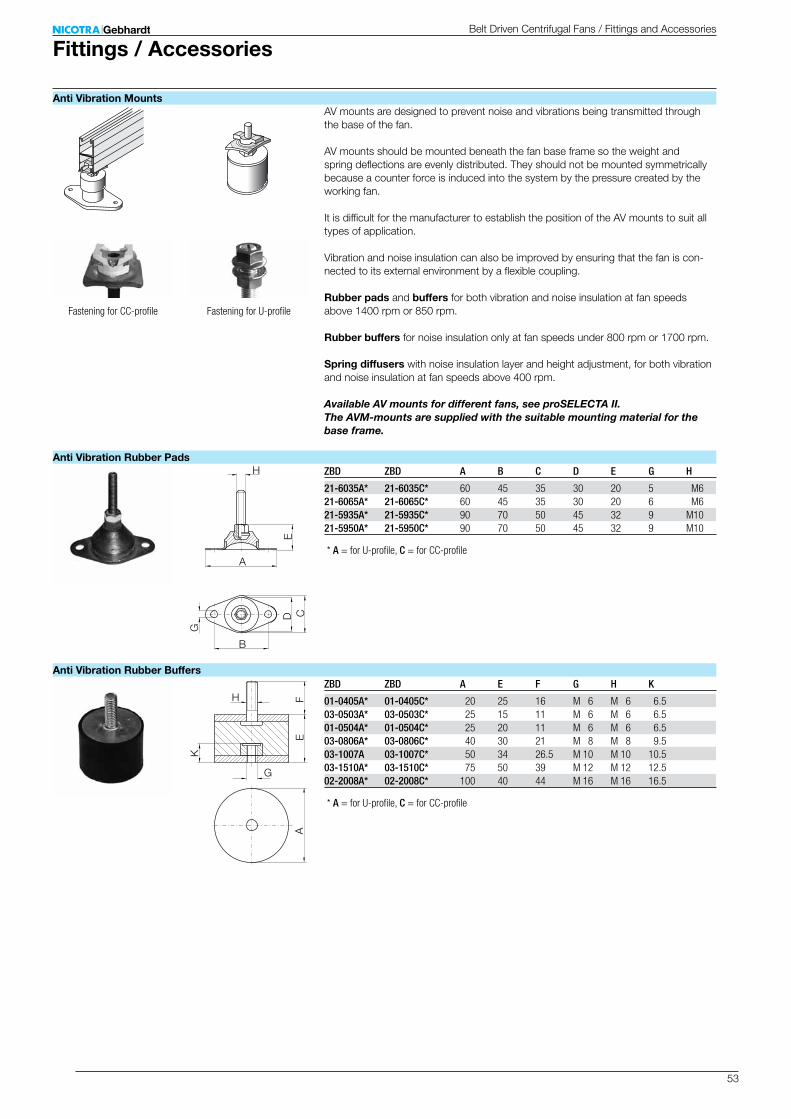
53
H
B
G
C
A
ED
H
G
EF
A
K
ZBD ZBD A B C D E G H
21-6035A* 21-6035C* 60 45 35 30 20 5 M621-6065A* 21-6065C* 60 45 35 30 20 6 M621-5935A* 21-5935C* 90 70 50 45 32 9 M1021-5950A* 21-5950C* 90 70 50 45 32 9 M10
ZBD ZBD A E F G H K
01-0405A* 01-0405C* 20 25 16 M 6 M 6 6.503-0503A* 03-0503C* 25 15 11 M 6 M 6 6.501-0504A* 01-0504C* 25 20 11 M 6 M 6 6.503-0806A* 03-0806C* 40 30 21 M 8 M 8 9.503-1007A 03-1007C* 50 34 26.5 M 10 M 10 10.503-1510A* 03-1510C* 75 50 39 M 12 M 12 12.502-2008A* 02-2008C* 100 40 44 M 16 M 16 16.5
AV mounts are designed to prevent noise and vibrations being transmitted through the base of the fan. AV mounts should be mounted beneath the fan base frame so the weight and spring deflections are evenly distributed. They should not be mounted symmetrically because a counter force is induced into the system by the pressure created by the working fan. It is difficult for the manufacturer to establish the position of the AV mounts to suit all types of application. Vibration and noise insulation can also be improved by ensuring that the fan is con-nected to its external environment by a flexible coupling.
Rubber pads and buffers for both vibration and noise insulation at fan speeds above 1400 rpm or 850 rpm.
Rubber buffers for noise insulation only at fan speeds under 800 rpm or 1700 rpm.
Spring diffusers with noise insulation layer and height adjustment, for both vibration and noise insulation at fan speeds above 400 rpm.
Available AV mounts for different fans, see proSELECTA II. The AVM-mounts are supplied with the suitable mounting material for the base frame.
* A = for U-profile, C = for CC-profile
* A = for U-profile, C = for CC-profile
Fittings / AccessoriesBelt Driven Centrifugal Fans / Fittings and Accessories
Anti Vibration Mounts
Anti Vibration Rubber Pads
Anti Vibration Rubber Buffers
Fastening for CC-profile Fastening for U-profile
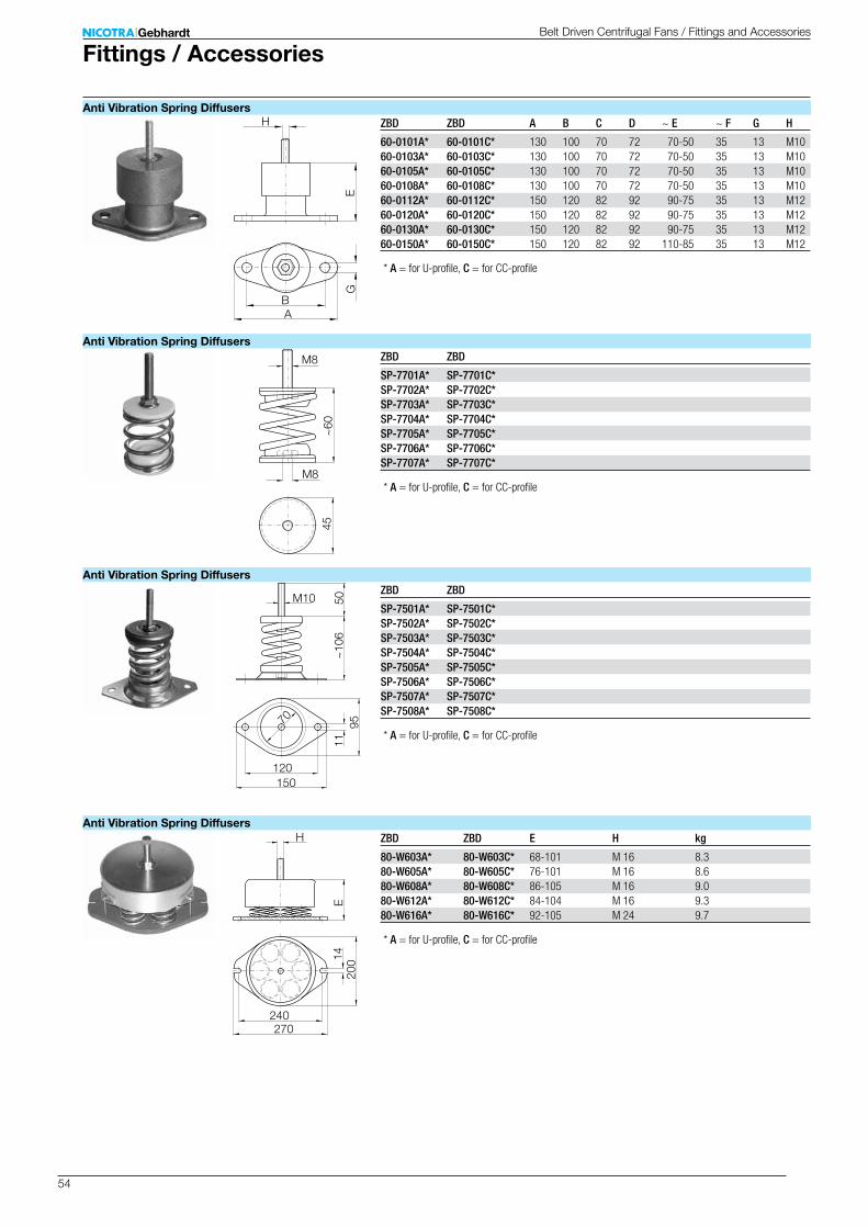
54
H
B
GE
A
M8
M8
45~
60
M10 50~
106
11
120150
70 95
240270
E14
200
H
ZBD ZBD A B C D ~ E ~ F G H
60-0101A* 60-0101C* 130 100 70 72 70-50 35 13 M1060-0103A* 60-0103C* 130 100 70 72 70-50 35 13 M1060-0105A* 60-0105C* 130 100 70 72 70-50 35 13 M1060-0108A* 60-0108C* 130 100 70 72 70-50 35 13 M1060-0112A* 60-0112C* 150 120 82 92 90-75 35 13 M1260-0120A* 60-0120C* 150 120 82 92 90-75 35 13 M1260-0130A* 60-0130C* 150 120 82 92 90-75 35 13 M1260-0150A* 60-0150C* 150 120 82 92 110-85 35 13 M12
ZBD ZBD
SP-7701A* SP-7701C*SP-7702A* SP-7702C*SP-7703A* SP-7703C*SP-7704A* SP-7704C*SP-7705A* SP-7705C*SP-7706A* SP-7706C*SP-7707A* SP-7707C*
ZBD ZBD
SP-7501A* SP-7501C*SP-7502A* SP-7502C*SP-7503A* SP-7503C*SP-7504A* SP-7504C*SP-7505A* SP-7505C*SP-7506A* SP-7506C*SP-7507A* SP-7507C*SP-7508A* SP-7508C*
ZBD ZBD E H kg
80-W603A* 80-W603C* 68-101 M 16 8.380-W605A* 80-W605C* 76-101 M 16 8.680-W608A* 80-W608C* 86-105 M 16 9.080-W612A* 80-W612C* 84-104 M 16 9.380-W616A* 80-W616C* 92-105 M 24 9.7
* A = for U-profile, C = for CC-profile
* A = for U-profile, C = for CC-profile
* A = for U-profile, C = for CC-profile
* A = for U-profile, C = for CC-profile
Belt Driven Centrifugal Fans / Fittings and Accessories
Fittings / Accessories
Anti Vibration Spring Diffusers
Anti Vibration Spring Diffusers
Anti Vibration Spring Diffusers
Anti Vibration Spring Diffusers
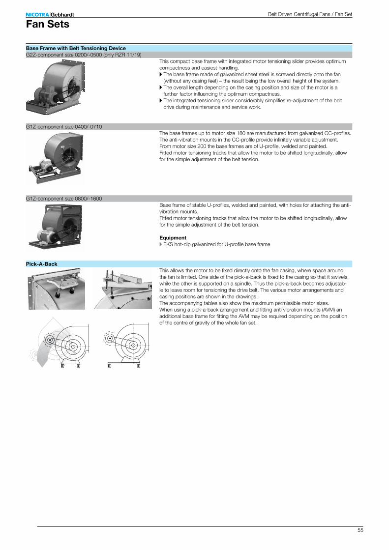
55
This compact base frame with integrated motor tensioning slider provides optimum compactness and easiest handling.A The base frame made of galvanized sheet steel is screwed directly onto the fan
(without any casing feet) – the result being the low overall height of the system.A The overall length depending on the casing position and size of the motor is a
further factor influencing the optimum compactness.A The integrated tensioning slider considerably simplifies re-adjustment of the belt
drive during maintenance and service work.
The base frames up to motor size 180 are manufactured from galvanized CC-profiles. The anti-vibration mounts in the CC-profile provide infinitely variable adjustment. From motor size 200 the base frames are of U-profile, welded and painted. Fitted motor tensioning tracks that allow the motor to be shifted longitudinally, allow for the simple adjustment of the belt tension.
Base frame of stable U-profiles, welded and painted, with holes for attaching the anti-vibration mounts. Fitted motor tensioning tracks that allow the motor to be shifted longitudinally, allow for the simple adjustment of the belt tension.
EquipmentA FKS hot-dip galvanized for U-profile base frame
This allows the motor to be fixed directly onto the fan casing, where space around the fan is limited. One side of the pick-a-back is fixed to the casing so that it swivels, while the other is supported on a spindle. Thus the pick-a-back becomes adjustab-le to leave room for tensioning the drive belt. The various motor arrangements and casing positions are shown in the drawings. The accompanying tables also show the maximum permissible motor sizes. When using a pick-a-back arrangement and fitting anti vibration mounts (AVM) an additional base frame for fitting the AVM may be required depending on the position of the centre of gravity of the whole fan set.
Belt Driven Centrifugal Fans / Fan Set
Fan Sets
Base Frame with Belt Tensioning DeviceG2Z-component size 0200/-0500 (only RZR 11/19)
G1Z-component size 0400/-0710
G1Z-component size 0800/-1600
Pick-A-Back
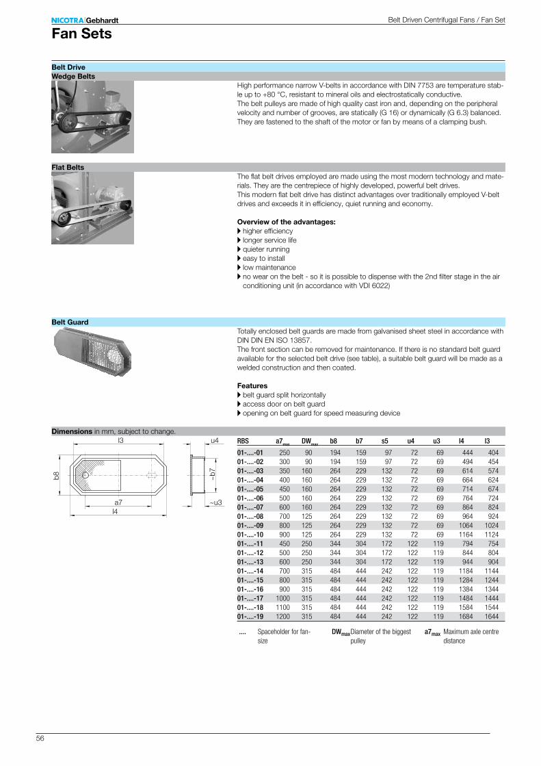
56
l3
l4a7
~b7
u4
~u3
b8
RBS a7max DWmax b8 b7 s5 u4 u3 l4 l3
01-....-01 250 90 194 159 97 72 69 444 40401-....-02 300 90 194 159 97 72 69 494 45401-....-03 350 160 264 229 132 72 69 614 57401-....-04 400 160 264 229 132 72 69 664 62401-....-05 450 160 264 229 132 72 69 714 67401-....-06 500 160 264 229 132 72 69 764 72401-....-07 600 160 264 229 132 72 69 864 82401-....-08 700 125 264 229 132 72 69 964 92401-....-09 800 125 264 229 132 72 69 1064 102401-....-10 900 125 264 229 132 72 69 1164 112401-....-11 450 250 344 304 172 122 119 794 75401-....-12 500 250 344 304 172 122 119 844 80401-....-13 600 250 344 304 172 122 119 944 90401-....-14 700 315 484 444 242 122 119 1184 114401-....-15 800 315 484 444 242 122 119 1284 124401-....-16 900 315 484 444 242 122 119 1384 134401-....-17 1000 315 484 444 242 122 119 1484 144401-....-18 1100 315 484 444 242 122 119 1584 154401-....-19 1200 315 484 444 242 122 119 1684 1644
High performance narrow V-belts in accordance with DIN 7753 are temperature stab-le up to +80 °C, resistant to mineral oils and electrostatically conductive. The belt pulleys are made of high quality cast iron and, depending on the peripheral velocity and number of grooves, are statically (G 16) or dynamically (G 6.3) balanced. They are fastened to the shaft of the motor or fan by means of a clamping bush.
The flat belt drives employed are made using the most modern technology and mate-rials. They are the centrepiece of highly developed, powerful belt drives. This modern flat belt drive has distinct advantages over traditionally employed V-belt drives and exceeds it in efficiency, quiet running and economy.
Overview of the advantages:A higher efficiencyA longer service lifeA quieter runningA easy to installA low maintenanceA no wear on the belt - so it is possible to dispense with the 2nd filter stage in the air
conditioning unit (in accordance with VDI 6022)
Totally enclosed belt guards are made from galvanised sheet steel in accordance with DIN DIN EN ISO 13857. The front section can be removed for maintenance. If there is no standard belt guard available for the selected belt drive (see table), a suitable belt guard will be made as a welded construction and then coated.
FeaturesA belt guard split horizontallyA access door on belt guardA opening on belt guard for speed measuring device
.... Spaceholder for fan-size
DWmax Diameter of the biggest pulley
a7max Maximum axle centre distance
Belt Driven Centrifugal Fans / Fan Set
Fan Sets
Belt DriveWedge Belts
Flat Belts
Belt Guard
Dimensions in mm, subject to change.
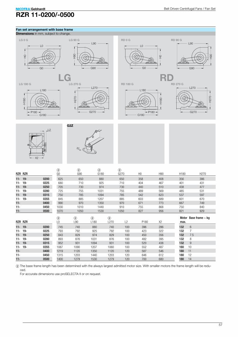
57
RZR 11-0200/-0500
LG RD
L2
X2
H27
0
G0
G270
H90
H18
0
G90
H0
H27
0
P180
G0
G270
H90
H18
0
G90
H0
L0 L0L90 L90
L180L180L270 L270
G180P180
G180
LG 270 GLG 180 G
LG 90 GLG 0 G
RD 180 G
RD 90 GRD 0 G
RD 270 G
X2
G2Z
2 2 2 2 L0 L90 L180 L270 L2 P180 X2
745 740 880 740 100 396 286 793 792 925 792 100 423 322 843 829 974 829 100 450 356 893 876 1031 876 100 482 395 952 931 1094 931 100 520 4381087 1090 1207 1060 100 552 4871219 1120 1350 1120 120 587 5461315 1203 1440 1203 120 646 6121400 1279 1530 1279 120 700 680
2 2 2 2 G0 G90 G180 G270 H0 H90 H180 H270
625 650 880 650 358 408 356 386 680 710 925 710 404 467 401 431 705 730 974 730 440 510 438 477 725 755 1031 755 489 569 485 531 750 785 1094 785 542 623 537 597 845 885 1207 885 603 689 601 670 990 970 1350 970 671 773 667 7491030 1010 1440 910 755 868 750 8401070 1050 1530 1050 827 956 821 929
132 6132 7132 7.5132 8132 9160 10180 11180 12180 14
RZR RZR
11- 19- 020011- 19- 022511- 19- 025011- 19- 028011- 19- 031511- 19- 035511- 040011- 045011- 0500
RZR RZR
11- 19- 020011- 19- 022511- 19- 025011- 19- 028011- 19- 031511- 19- 035511- 040011- 045011- 0500
2 The base frame length has been determined with the always largest admitted motor size. With smaller motors the frame length will be redu-ced. For accurate dimensions use proSELECTA II or on request.
Belt Driven Centrifugal Fans / Fan Set
Fan set arrangement with base frame
Motor max.
Base frame ~ kg
Dimensions in mm, subject to change.

58
RZR 11-0400/-0710
LG RD
L2
X2
G3
H27
0
G180
G0
G270
H90
H18
0
G90G3
G3
G3
H0
G3
H27
0
G180
G0
G270
H90
H18
0
G90 G3
G3
G3
H0
LG 270 G LG 180 G
LG 90 G LG 0 G
RD 180 G
RD 90 G RD 0 G
RD 270 G
P3
P2
P4
P1
P3
P2
P4
P1
X2X2
G1Z (CC) G1Z (U)
H0 H90 H180 H270 L2 P1 P2 P3 P4 X2
671 773 667 749 120 275 355 669 275 550 755 868 750 840 120 320 408 718 320 614 827 956 821 929 120 348 452 766 348 682 921 1071 914 1041 150 384 502 851 384 7591028 1195 1021 1168 150 432 566 915 432 8461152 1341 1143 1316 180 479 625 1014 479 9431152 1341 1143 1316 180 – – – – 943
2 2 2 2 G0 G90 G180 G270
1240 1300 1650 12401300 1350 1740 12981434 1405 1772 14051558 1508 1908 15081600 1574 2006 15741708 1680 2145 16801700 1700 2115 1700
63-71 80-90 100-132 160-180 200-225 250-280
82-CC 82-CC 82-CC 82-CC 80-U 3 –82-CC 82-CC 82-CC 82-CC 80-U 3 –82-CC 82-CC 82-CC 82-CC 80-U 3 –82-CC 82-CC 82-CC 82-CC 80-U 3 –– 82-CC 82-CC 82-CC 80-U 3 –– 82-CC 82-CC 82-CC – –– – – – 100-U 120-U 3
CC 80-U 100-U
225 31 3 3
225 32 3 3
225 33 60 –225 34 63 –225 35 68 –180 37 – –250 – 94 145
RZR
11- 040011- 045011- 050011- 056011- 063011- 071011- 0710-U
RZR
11- 040011- 045011- 050011- 056011- 063011- 071011- 0710-U
2 The base frame length has been determined with the always largest admitted motor size. With smaller motors the frame length will be reduced. For accurate dimensions use proSELECTA II or on request.
3 Dimensions on request
Anti-vibration mounts are supplied with AV brackets included.
Belt Driven Centrifugal Fans / Fan Set
Dimensions in mm, subject to change.Fan set arrangement with base frame
Motor max.
Base frame ~ kg
G3 for motor size

59
RZR 12-0200/-0710
LG RD
L2
X2
P2
G3 P1
P4
H27
0
P3G180
G0
G270
H90
H18
0
G90G3
G3
G3
P2
H0
G3 P1
P4
H27
0
P3G180
G0
G270
H90
H18
0
G90 G3
G3
G3
H0
LG 270 GLG 180 G
LG 90 G LG 0 G
RD 180 G
RD 90 G RD 0 G
RD 270 G
H0 H90 H180 H270 L2 X2
4 4 4 4 4 44 4 4 4 4 44 4 4 4 4 44 4 4 4 4 44 4 4 4 4 44 4 4 4 4 4 669 769 669 750 120 550 753 865 753 841 120 614 825 955 825 931 120 682 920 1067 920 1046 150 7591027 1195 1027 1173 150 8461152 1341 1152 1324 180 9431152 1341 1152 1324 180 –
2 2 2 2 G0 G90 G180 G270
4 4 4 44 4 4 44 4 4 44 4 4 44 4 4 44 4 4 41430 1312 1655 13121522 1388 1740 13881610 1460 1830 14601736 1561 1958 15611865 1670 2078 16702008 1784 2235 17842035 1840 2235 1840
63-71 80-90 100-132 160-180 200-225 250-280
– – – – – –– – – – – –– – – – – –– – – – – –– – – – – –– – – – – –82-CC 82-CC 82-CC 82-CC 80-U 3 –82-CC 82-CC 82-CC 82-CC 80-U 3 –82-CC 82-CC 82-CC 82-CC 80-U 3 –82-CC 82-CC 82-CC 82-CC 80-U 3 –– 82-CC 82-CC 82-CC 80-U 3 –– 82-CC 82-CC 82-CC – –– – – – 100-U 120-U 3
CC 80-U 100-U
4 4 4 44 4 4 44 4 4 44 4 4 44 4 4 44 4 4 4225 31 3 3
225 32 3 3
225 33 60 –225 34 63 –225 35 68 –180 37 – –250 – 94 155
G1Z (CC) G1Z (U)
RZR
12- 020012- 022512- 025012- 028012- 031512- 035512- 040012- 045012- 050012- 056012- 063012- 071012- 0710-U
RZR
12- 020012- 022512- 025012- 028012- 031512- 035512- 040012- 045012- 050012- 056012- 063012- 071012- 0710-U
X2X2
Anti-vibration mounts are supplied with AV brackets included.
2 The base frame length has been determined with the always largest admitted motor size. With smaller motors the frame length will be reduced. For accurate dimensions use proSELECTA II or on request.
3 Dimensions on request4 The RZR 12-0200 to 0355 can only be supplied as standard basic
models.
Belt Driven Centrifugal Fans / Fan Set
Dimensions in mm, subject to change.Fan set arrangement with base frame
Motor max.
Base frame ~ kg
G3 for motor size
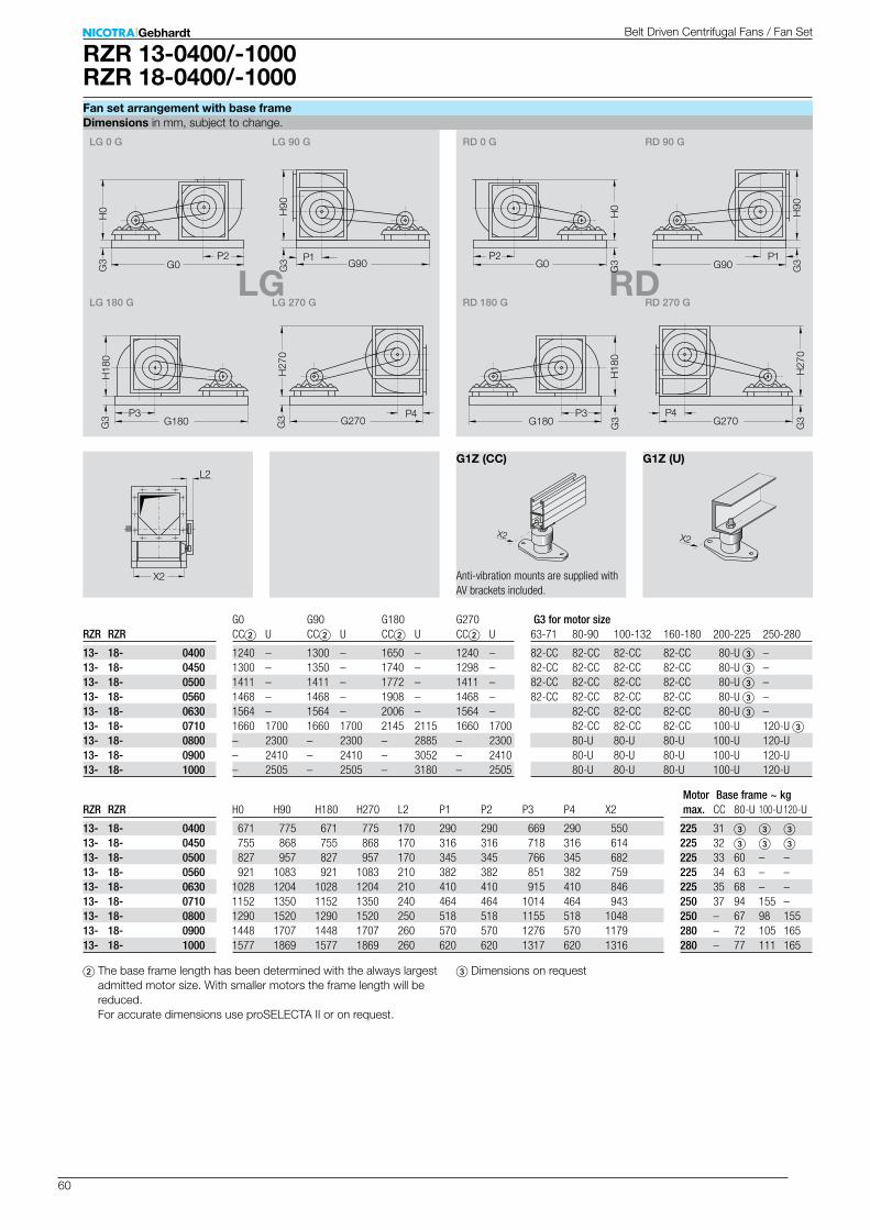
60
RZR 13-0400/-1000RZR 18-0400/-1000
LG RDP2
G3 P1
P4
H27
0
P3G180
G0
G270
H90
H18
0
G90G3
G3
G3
P2
H0
G3 P1
P4
H27
0
P3G180
G0
G270
H90
H18
0
G90 G3
G3
G3
H0
LG 270 GLG 180 G
LG 90 G LG 0 G
RD 180 G
RD 90 G RD 0 G
RD 270 G
H0 H90 H180 H270 L2 P1 P2 P3 P4 X2
671 775 671 775 170 290 290 669 290 550 755 868 755 868 170 316 316 718 316 614 827 957 827 957 170 345 345 766 345 682 921 1083 921 1083 210 382 382 851 382 7591028 1204 1028 1204 210 410 410 915 410 8461152 1350 1152 1350 240 464 464 1014 464 9431290 1520 1290 1520 250 518 518 1155 518 10481448 1707 1448 1707 260 570 570 1276 570 11791577 1869 1577 1869 260 620 620 1317 620 1316
G0 G90 G180 G270 CC2 U CC2 U CC2 U CC2 U
1240 – 1300 – 1650 – 1240 –1300 – 1350 – 1740 – 1298 –1411 – 1411 – 1772 – 1411 –1468 – 1468 – 1908 – 1468 –1564 – 1564 – 2006 – 1564 –1660 1700 1660 1700 2145 2115 1660 1700– 2300 – 2300 – 2885 – 2300– 2410 – 2410 – 3052 – 2410– 2505 – 2505 – 3180 – 2505
63-71 80-90 100-132 160-180 200-225 250-280
82-CC 82-CC 82-CC 82-CC 80-U 3 –82-CC 82-CC 82-CC 82-CC 80-U 3 –82-CC 82-CC 82-CC 82-CC 80-U 3 –82-CC 82-CC 82-CC 82-CC 80-U 3 – 82-CC 82-CC 82-CC 80-U 3 – 82-CC 82-CC 82-CC 100-U 120-U 3 80-U 80-U 80-U 100-U 120-U 80-U 80-U 80-U 100-U 120-U 80-U 80-U 80-U 100-U 120-U
CC 80-U 100-U 120-U
225 31 3 3 3
225 32 3 3 3
225 33 60 – –225 34 63 – –225 35 68 – –250 37 94 155 –250 – 67 98 155280 – 72 105 165280 – 77 111 165
G1Z (CC) G1Z (U)L2
X2
RZR RZR
13- 18- 040013- 18- 045013- 18- 050013- 18- 056013- 18- 063013- 18- 071013- 18- 080013- 18- 090013- 18- 1000
RZR RZR
13- 18- 040013- 18- 045013- 18- 050013- 18- 056013- 18- 063013- 18- 071013- 18- 080013- 18- 090013- 18- 1000
X2X2
2 The base frame length has been determined with the always largest admitted motor size. With smaller motors the frame length will be reduced. For accurate dimensions use proSELECTA II or on request.
3 Dimensions on request
Anti-vibration mounts are supplied with AV brackets included.
Belt Driven Centrifugal Fans / Fan Set
Dimensions in mm, subject to change.Fan set arrangement with base frame
Motor max.
Base frame ~ kg
G3 for motor size
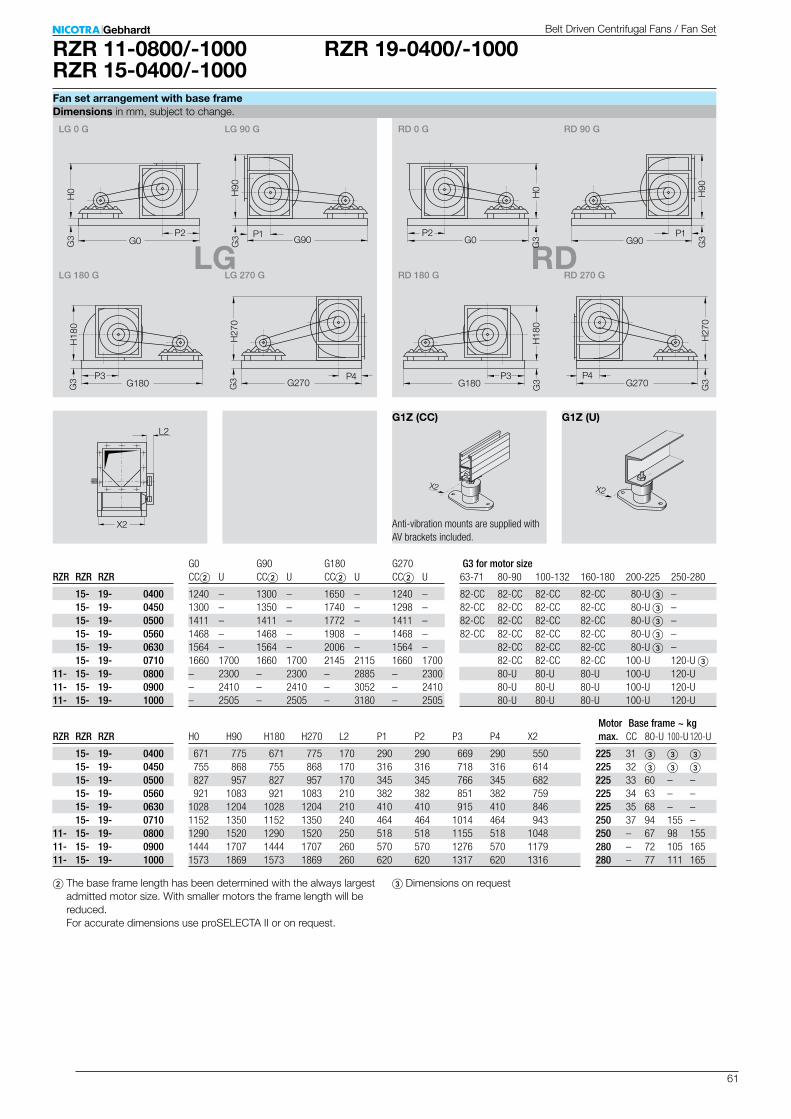
61
RZR 19-0400/-1000RZR 11-0800/-1000RZR 15-0400/-1000
LG RDP2
G3 P1
P4
H27
0
P3G180
G0
G270
H90
H18
0
G90G3
G3
G3
P2
H0
G3 P1
P4
H27
0
P3G180
G0
G270
H90
H18
0
G90 G3
G3
G3
H0
LG 270 GLG 180 G
LG 90 G LG 0 G
RD 180 G
RD 90 G RD 0 G
RD 270 G
G1Z (CC) G1Z (U)L2
X2
H0 H90 H180 H270 L2 P1 P2 P3 P4 X2
671 775 671 775 170 290 290 669 290 550 755 868 755 868 170 316 316 718 316 614 827 957 827 957 170 345 345 766 345 682 921 1083 921 1083 210 382 382 851 382 7591028 1204 1028 1204 210 410 410 915 410 8461152 1350 1152 1350 240 464 464 1014 464 9431290 1520 1290 1520 250 518 518 1155 518 10481444 1707 1444 1707 260 570 570 1276 570 11791573 1869 1573 1869 260 620 620 1317 620 1316
G0 G90 G180 G270 CC2 U CC2 U CC2 U CC2 U
1240 – 1300 – 1650 – 1240 –1300 – 1350 – 1740 – 1298 –1411 – 1411 – 1772 – 1411 –1468 – 1468 – 1908 – 1468 –1564 – 1564 – 2006 – 1564 –1660 1700 1660 1700 2145 2115 1660 1700– 2300 – 2300 – 2885 – 2300– 2410 – 2410 – 3052 – 2410– 2505 – 2505 – 3180 – 2505
63-71 80-90 100-132 160-180 200-225 250-280
82-CC 82-CC 82-CC 82-CC 80-U 3 –82-CC 82-CC 82-CC 82-CC 80-U 3 –82-CC 82-CC 82-CC 82-CC 80-U 3 –82-CC 82-CC 82-CC 82-CC 80-U 3 – 82-CC 82-CC 82-CC 80-U 3 – 82-CC 82-CC 82-CC 100-U 120-U 3 80-U 80-U 80-U 100-U 120-U 80-U 80-U 80-U 100-U 120-U 80-U 80-U 80-U 100-U 120-U
CC 80-U 100-U 120-U
225 31 3 3 3
225 32 3 3 3
225 33 60 – –225 34 63 – –225 35 68 – –250 37 94 155 –250 – 67 98 155280 – 72 105 165280 – 77 111 165
RZR RZR RZR
15- 19- 0400 15- 19- 0450 15- 19- 0500 15- 19- 0560 15- 19- 0630 15- 19- 071011- 15- 19- 080011- 15- 19- 090011- 15- 19- 1000
RZR RZR RZR
15- 19- 0400 15- 19- 0450 15- 19- 0500 15- 19- 0560 15- 19- 0630 15- 19- 071011- 15- 19- 080011- 15- 19- 090011- 15- 19- 1000
X2X2
2 The base frame length has been determined with the always largest admitted motor size. With smaller motors the frame length will be reduced. For accurate dimensions use proSELECTA II or on request.
3 Dimensions on request
Belt Driven Centrifugal Fans / Fan Set
Dimensions in mm, subject to change.Fan set arrangement with base frame
Anti-vibration mounts are supplied with AV brackets included.
Motor max.
Base frame ~ kg
G3 for motor size
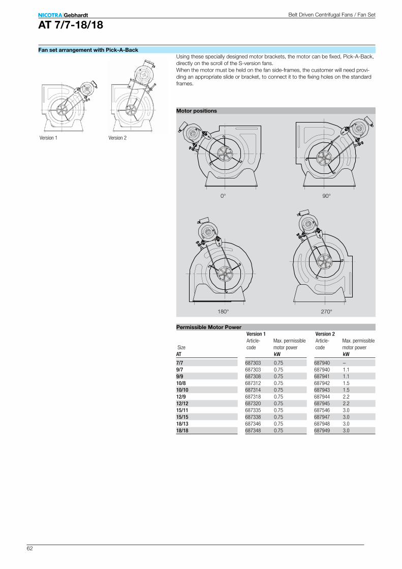
62
AT 7/7-18/18
kW
687303 0.75687303 0.75687308 0.75687312 0.75687314 0.75687318 0.75687320 0.75687335 0.75687338 0.75687346 0.75687348 0.75
AT
7/79/79/9 10/810/1012/912/1215/1115/1518/1318/18
90°0°
270°180°
kW
687940 –687940 1.1687941 1.1687942 1.5687943 1.5687944 2.2687945 2.2687546 3.0687947 3.0687948 3.0687949 3.0
Using these specially designed motor brackets, the motor can be fixed, Pick-A-Back, directly on the scroll of the S-version fans. When the motor must be held on the fan side-frames, the customer will need provi-ding an appropriate slide or bracket, to connect it to the fixing holes on the standard frames.
Belt Driven Centrifugal Fans / Fan Set
Permissible Motor Power
Motor positions
Fan set arrangement with Pick-A-Back
Article- codeSize
Max. permissible motor power
Version 1 Version 2
Article- code
Max. permissible motor power
Version 1 Version 2
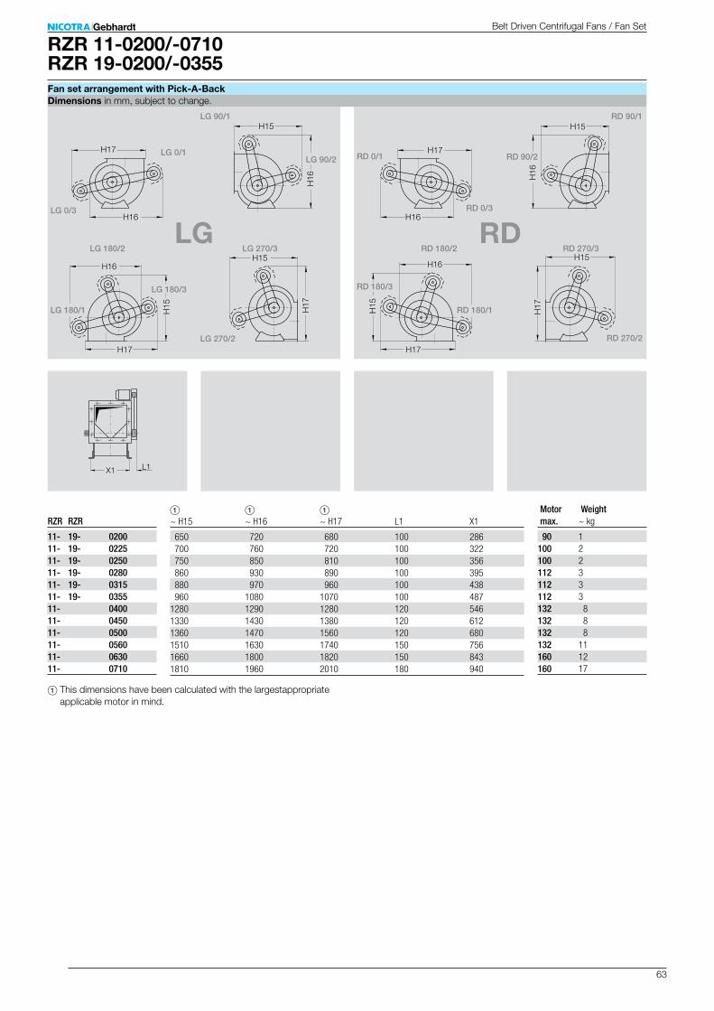
63
RZR 11-0200/-0710RZR 19-0200/-0355
1 1 1 ~ H15 ~ H16 ~ H17 L1 X1
650 720 680 100 286 700 760 720 100 322 750 850 810 100 356 860 930 890 100 395 880 970 960 100 438 960 1080 1070 100 4871280 1290 1280 120 5461330 1430 1380 120 6121360 1470 1560 120 6801510 1630 1740 150 7561660 1800 1820 150 8431810 1960 2010 180 940
~ kg
90 1100 2100 2112 3112 3112 3132 8132 8132 8132 11160 12160 17
RZR RZR
11- 19- 020011- 19- 022511- 19- 025011- 19- 028011- 19- 031511- 19- 035511- 040011- 045011- 050011- 056011- 063011- 0710
LG RD
L1X1
H17
H16
H15
H16
H
17
H15 H16
H17
H15
H17
H16
H15
H16
H
17
H15 H16
H17
H15
RD 0/1
RD 90/1
RD 90/2
RD 270/3
RD 270/2
RD 180/3
RD 180/2
RD 180/1
RD 0/3
LG 0/1
LG 90/1
LG 90/2
LG 270/3
LG 270/2
LG 180/3
LG 180/2
LG 180/1
LG 0/3
1 This dimensions have been calculated with the largestappropriate applicable motor in mind.
Belt Driven Centrifugal Fans / Fan Set
Dimensions in mm, subject to change.Fan set arrangement with Pick-A-Back
Motor max.
Weight

64
RZR 12-0200/-0710
1 1 1 ~ H15 ~ H16 ~ H17 ~ L1 X1
670 670 690 100 286 710 730 780 100 322 850 840 860 100 356 880 920 930 100 395 950 950 1030 100 4381080 1090 1130 100 4871190 1290 1280 120 5461330 1430 1390 120 6121360 1470 1560 120 6801500 1620 1630 150 7561650 1790 1810 150 8431800 1950 2000 180 940
~ kg
90 1100 1100 2112 2112 3112 3132 7132 7132 8132 11160 12160 17
RZR
12- 020012- 022512- 025012- 028012- 031512- 035512- 040012- 045012- 050012- 056012- 063012- 0710
LG RD
L1X1
H17
H16
H15
H16
H
17
H15 H16
H17
H15
H17
H16
H15
H16
H
17
H15 H16
H17
H15
RD 0/1
RD 90/1
RD 90/2
RD 270/3
RD 270/2
RD 180/3
RD 180/2
RD 180/1
RD 0/3
LG 0/1
LG 90/1
LG 90/2
LG 270/3
LG 270/2
LG 180/3
LG 180/2
LG 180/1
LG 0/3
1 This dimensions have been calculated with the largestappropriate applicable motor in mind.
Belt Driven Centrifugal Fans / Fan Set
Dimensions in mm, subject to change.Fan set arrangement with Pick-A-Back
Motor max.
Weight

65
RZR 13-0400/-1000RZR 18-0400/-1000
1 1 1 ~ H15 ~ H16 ~ H17 ~ L1 X1
1280 1300 1300 170 5481320 1430 1380 170 6121350 1560 1550 170 6831530 1700 1730 210 7591640 1870 1820 210 8451800 1970 2010 240 9421970 2150 2150 250 10532150 2400 2350 260 11792230 2630 2550 260 1317
~ kg
132 10132 11132 12160 15160 16160 23160 30160 33160 36
RZR RZR
13- 18- 040013- 18- 045013- 18- 0500 13- 18- 056013- 18- 063013- 18- 071013- 18- 080013- 18- 090013- 18- 1000
LG RD
L1X1
H16
H17H15
H16
H17
H15
RD 90/1
RD 270/3RD 180/2
LG 90/1
LG 270/3LG 180/2
1 This dimensions have been calculated with the largestappropriate applicable motor in mind.
Belt Driven Centrifugal Fans / Fan Set
Dimensions in mm, subject to change.Fan set arrangement with Pick-A-Back
Motor max.
Weight
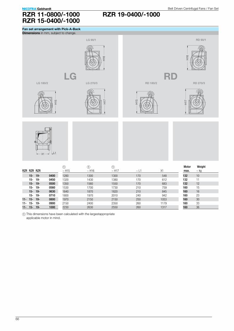
66
RZR 19-0400/-1000RZR 11-0800/-1000RZR 15-0400/-1000
1 1 1 ~ H15 ~ H16 ~ H17 ~ L1 X1
1280 1300 1300 170 5481320 1430 1380 170 6121350 1560 1550 170 6831530 1700 1730 210 7591640 1870 1820 210 8451800 1970 2010 240 9421970 2150 2150 250 10532150 2400 2350 260 11792230 2630 2550 260 1317
~ kg
132 10132 11132 12160 15160 16160 23160 30160 33160 36
RZR RZR RZR
15- 19- 0400 15- 19- 0450 15- 19- 0500 15- 19- 0560 15- 19- 0630 15- 19- 071011- 15- 19- 080011- 15- 19- 090011- 15- 19- 1000
LG RD
L1X1
H16
H17H15
H16
H17
H15
RD 90/1
RD 270/3RD 180/2
LG 90/1
LG 270/3LG 180/2
1 This dimensions have been calculated with the largestappropriate applicable motor in mind.
Belt Driven Centrifugal Fans / Fan Set
Dimensions in mm, subject to change.Fan set arrangement with Pick-A-Back
Motor max.
Weight
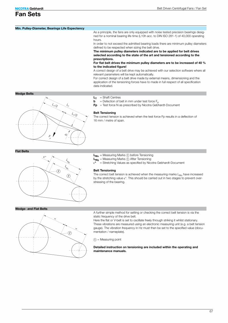
67
bFp
LT/2
LT/2
LT
ε*
LMu
LMg
=
=
As a principle, the fans are only equipped with noise tested precision bearings desig-ned for a nominal bearing life time (L10h acc. to DIN ISO 281-1) of 40,000 operating hours. In order to not exceed the admitted bearing loads there are minimum pulley diameters defined to be respected when sizing the belt drive.The minimum pulley diameters indicated are to be applied for belt drives selected according to the state of the art and tensioned according to the prescriptions. For flat belt drives the minimum pulley diameters are to be increased of 40 % to the indicated figure!A correct design of a belt drive may be achieved with our selection software where all relevant parameters will be kept automatically. For correct design of a belt drive made by external means, dimensioning and the application of the tensioning forces have to made in full respect of all specification data indicated.
LT = Shaft Centresb = Defection of belt in mm under test force FpFp = Test force N as prescribed by Nicotra Gebhardt-Document
Belt TensioningThe correct tension is achieved when the test force Fp results in a deflection of 16 mm / metre of span.
LMu = Measuring Marks 1 before TensioningLMg = Measuring Marks 1 After Tensioninge* = Stretching Values as specified by Nicotra Gebhardt-Document
Belt TensioningThe correct belt tension is achieved when the measuring marks LMu have increased by the stretching value e*. This should be carried out in two stages to prevent over-stressing of the bearing.
A further simple method for setting or checking the correct belt tension is via the static frequency of the drive belt. Here the flat or V-belt is set to oscillate freely through striking it whilst stationary. These vibrations are measured using an electronic measuring unit (e.g. a belt tension gauge). The vibration frequency in Hz must then be set to the specified value (docu-mentation / nameplate). 1 = Measuring point
Detailed instruction on tensioning are included within the operating and maintenance manuals.
Belt Driven Centrifugal Fans / Fan Set
Fan Sets
Min. Pulley-Diameter, Bearings Life Expectency
Wedge Belts
Wedge- and Flat Belts
Flat Belts
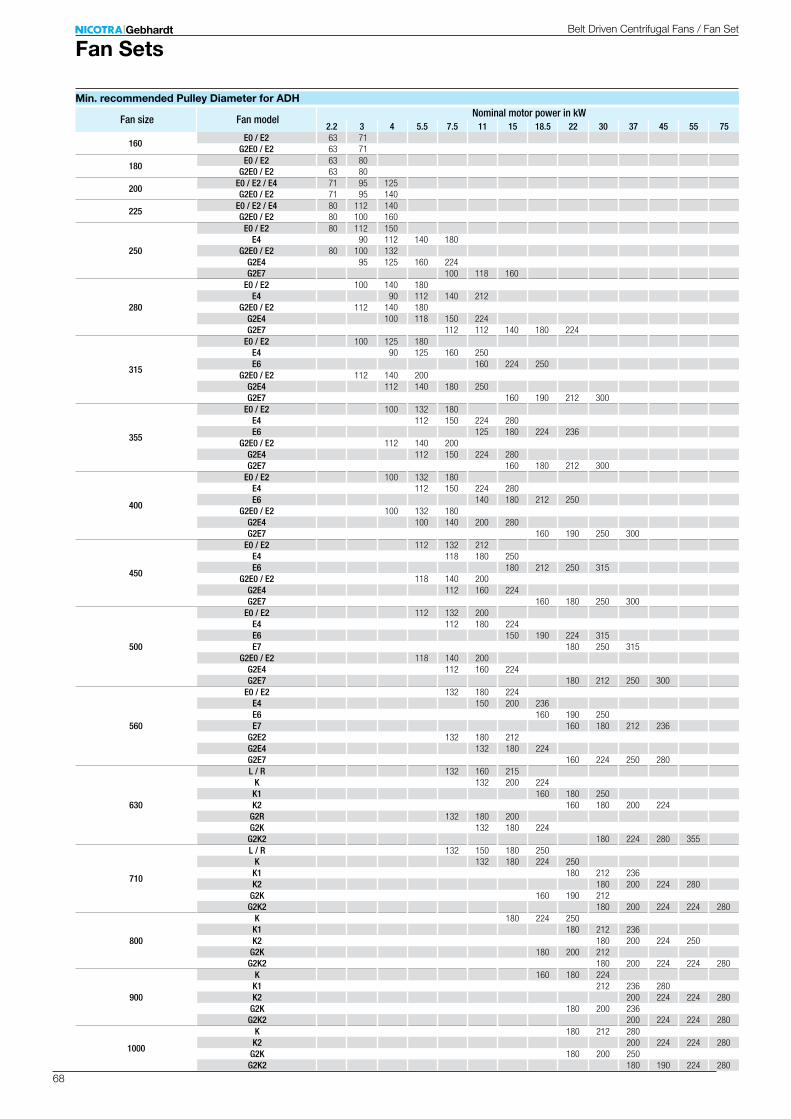
68
2.2 3 4 5.5 7.5 11 15 18.5 22 30 37 45 55 75
160E0 / E2 63 71
G2E0 / E2 63 71
180E0 / E2 63 80
G2E0 / E2 63 80
200E0 / E2 / E4 71 95 125G2E0 / E2 71 95 140
225E0 / E2 / E4 80 112 140G2E0 / E2 80 100 160
250
E0 / E2 80 112 150E4 90 112 140 180
G2E0 / E2 80 100 132G2E4 95 125 160 224G2E7 100 118 160
280
E0 / E2 100 140 180E4 90 112 140 212
G2E0 / E2 112 140 180G2E4 100 118 150 224G2E7 112 112 140 180 224
315
E0 / E2 100 125 180E4 90 125 160 250E6 160 224 250
G2E0 / E2 112 140 200G2E4 112 140 180 250G2E7 160 190 212 300
355
E0 / E2 100 132 180E4 112 150 224 280E6 125 180 224 236
G2E0 / E2 112 140 200G2E4 112 150 224 280G2E7 160 180 212 300
400
E0 / E2 100 132 180E4 112 150 224 280E6 140 180 212 250
G2E0 / E2 100 132 180G2E4 100 140 200 280G2E7 160 190 250 300
450
E0 / E2 112 132 212E4 118 180 250E6 180 212 250 315
G2E0 / E2 118 140 200G2E4 112 160 224G2E7 160 180 250 300
500
E0 / E2 112 132 200E4 112 180 224E6 150 190 224 315E7 180 250 315
G2E0 / E2 118 140 200G2E4 112 160 224G2E7 180 212 250 300
560
E0 / E2 132 180 224E4 150 200 236E6 160 190 250E7 160 180 212 236
G2E2 132 180 212G2E4 132 180 224G2E7 160 224 250 280
630
L / R 132 160 215K 132 200 224K1 160 180 250K2 160 180 200 224
G2R 132 180 200G2K 132 180 224
G2K2 180 224 280 355
710
L / R 132 150 180 250K 132 180 224 250K1 180 212 236K2 180 200 224 280
G2K 160 190 212G2K2 180 200 224 224 280
800
K 180 224 250K1 180 212 236K2 180 200 224 250
G2K 180 200 212G2K2 180 200 224 224 280
900
K 160 180 224K1 212 236 280K2 200 224 224 280
G2K 180 200 236G2K2 200 224 224 280
1000
K 180 212 280K2 200 224 224 280
G2K 180 200 250G2K2 180 190 224 280
Fan SetsBelt Driven Centrifugal Fans / Fan Set
Min. recommended Pulley Diameter for ADH
Fan size Fan modelNominal motor power in kW
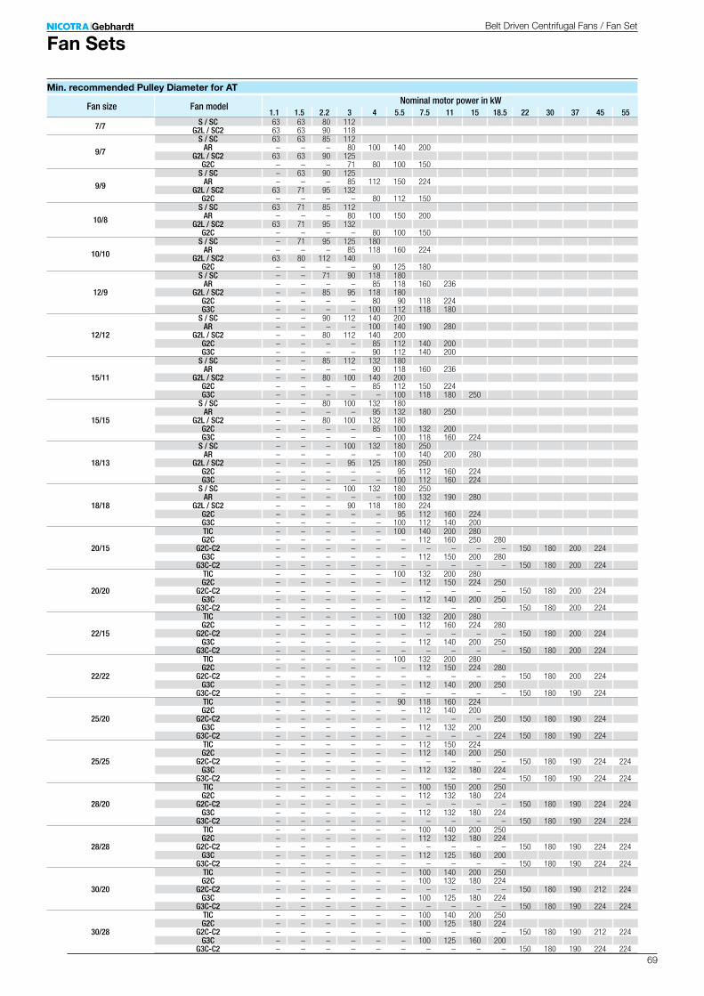
69
1.1 1.5 2.2 3 4 5.5 7.5 11 15 18.5 22 30 37 45 55
7/7 S / SC 63 63 80 112G2L / SC2 63 63 90 118
9/7
S / SC 63 63 85 112AR – – – 80 100 140 200
G2L / SC2 63 63 90 125G2C – – – 71 80 100 150
9/9
S / SC – 63 90 125AR – – – 85 112 150 224
G2L / SC2 63 71 95 132G2C – – – – 80 112 150
10/8
S / SC 63 71 85 112AR – – – 80 100 150 200
G2L / SC2 63 71 95 132G2C – – – – 80 100 150
10/10
S / SC – 71 95 125 180AR – – – 85 118 160 224
G2L / SC2 63 80 112 140G2C – – – – 90 125 180
12/9
S / SC – – 71 90 118 180AR – – – – 85 118 160 236
G2L / SC2 – – 85 95 118 180G2C – – – – 80 90 118 224G3C – – – – 100 112 118 180
12/12
S / SC – – 90 112 140 200AR – – – – 100 140 190 280
G2L / SC2 – – 80 112 140 200G2C – – – – 85 112 140 200G3C – – – – 90 112 140 200
15/11
S / SC – – 85 112 132 180AR – – – – 90 118 160 236
G2L / SC2 – – 80 100 140 200G2C – – – – 85 112 150 224G3C – – – – – 100 118 180 250
15/15
S / SC – – 80 100 132 180AR – – – – 95 132 180 250
G2L / SC2 – – 80 100 132 180G2C – – – – 85 100 132 200G3C – – – – – 100 118 160 224
18/13
S / SC – – – 100 132 180 250AR – – – – – 100 140 200 280
G2L / SC2 – – – 95 125 180 250G2C – – – – – 95 112 160 224G3C – – – – – 100 112 160 224
18/18
S / SC – – – 100 132 180 250AR – – – – – 100 132 190 280
G2L / SC2 – – – 90 118 180 224G2C – – – – – 95 112 160 224G3C – – – – – 100 112 140 200
20/15
TIC – – – – – 100 140 200 280G2C – – – – – – 112 160 250 280
G2C-C2 – – – – – – – – – – 150 180 200 224G3C – – – – – – 112 150 200 280
G3C-C2 – – – – – – – – – – 150 180 200 224
20/20
TIC – – – – – 100 132 200 280G2C – – – – – – 112 150 224 250
G2C-C2 – – – – – – – – – – 150 180 200 224G3C – – – – – – 112 140 200 250
G3C-C2 – – – – – – – – – – 150 180 200 224
22/15
TIC – – – – – 100 132 200 280G2C – – – – – – 112 160 224 280
G2C-C2 – – – – – – – – – – 150 180 200 224G3C – – – – – – 112 140 200 250
G3C-C2 – – – – – – – – – – 150 180 200 224
22/22
TIC – – – – – 100 132 200 280G2C – – – – – – 112 150 224 280
G2C-C2 – – – – – – – – – – 150 180 200 224G3C – – – – – – 112 140 200 250
G3C-C2 – – – – – – – – – – 150 180 190 224
25/20
TIC – – – – – 90 118 160 224G2C – – – – – – 112 140 200
G2C-C2 – – – – – – – – – 250 150 180 190 224G3C – – – – – – 112 132 200
G3C-C2 – – – – – – – – – 224 150 180 190 224
25/25
TIC – – – – – – 112 150 224G2C – – – – – – 112 140 200 250
G2C-C2 – – – – – – – – – – 150 180 190 224 224G3C – – – – – – 112 132 180 224
G3C-C2 – – – – – – – – – – 150 180 190 224 224
28/20
TIC – – – – – – 100 150 200 250G2C – – – – – – 112 132 180 224
G2C-C2 – – – – – – – – – – 150 180 190 224 224G3C – – – – – – 112 132 180 224
G3C-C2 – – – – – – – – – – 150 180 190 224 224
28/28
TIC – – – – – – 100 140 200 250G2C – – – – – – 112 132 180 224
G2C-C2 – – – – – – – – – – 150 180 190 224 224G3C – – – – – – 112 125 160 200
G3C-C2 – – – – – – – – – – 150 180 190 224 224
30/20
TIC – – – – – – 100 140 200 250G2C – – – – – – 100 132 180 224
G2C-C2 – – – – – – – – – – 150 180 190 212 224G3C – – – – – – 100 125 180 224
G3C-C2 – – – – – – – – – – 150 180 190 224 224
30/28
TIC – – – – – – 100 140 200 250G2C – – – – – – 100 125 180 224
G2C-C2 – – – – – – – – – – 150 180 190 212 224G3C – – – – – – 100 125 160 200
G3C-C2 – – – – – – – – – – 150 180 190 224 224
Fan SetsBelt Driven Centrifugal Fans / Fan Set
Min. recommended Pulley Diameter for AT
Fan size Fan modelNominal motor power in kW

70
2.2 3 4 5.5 7.5 11 15 18.5 22 30 37 45 55 750180 E0 / E2 63 630200 E0 / E2 / E4 63 630225 E0 / E2 / E4 63 63 71
0250
E0 / E2 71 80E4 71 71 90
G2E4 80 80 90G2E7 85 112
0280
E0 / E2 80 100E4 90 100
G2E0 / E2G2E4 90 100G2E7 90 125
0315
E0 / E2 90 118E4 90 112E6 90 100
G2E0 / E2G2E4 80 90G2E7 90 112
0355
E0 / E2 85 100 112E4 90 112 125E6 100 112 118
G2E0 / E2G2E4 90 125G2E7 90 112
0400
E0 / E2 112 140E4 100 132 180E6 118 140 150
G2E4 100 112 112G2E7 112 125 160
0450
E0 / E2 112 125 180E4 112 140 180E6 125 140 160 212
G2E4 100 118 140G2E7 112 125 160
0500
E0 / E2 125 132 160E4 132 150 200E6 140 140 150 200E7 118 125 150 200
G2E4 100 118 150G2E7 140 150 180
0560
E0 / E2 140 180 224E4 150 200 224E6 150 160 212E7 140 160 160
G2E2G2E4 112 140G2E7 180 200 280
0630
R 140 180 250K 150 200 250K1 180 180 236K2 150 180 190 224
G2K 140 190G2K2 180 200 280 355
0710
R 180 224K 224 250 315
K1 180 224 250K2 200 212 224
G2K 180 200 280G2K2 224 224 280
0800
K 200 250 280K1 180 212 250K2 212 224 224
G2K 180 190 250G2K2 224 250 280
0900
K 160 180 250K1 212 250 280K2 224 224 280
G2K 224 250 315G2K2 224 224 280
1000
K 180 236 315K2 224 224 300
G2K 190 224 280G2K2 224 224 280
Fan SetsBelt Driven Centrifugal Fans / Fan Set
Min. recommended Pulley Diameter for RDH
Fan size Fan modelNominal motor power in kW
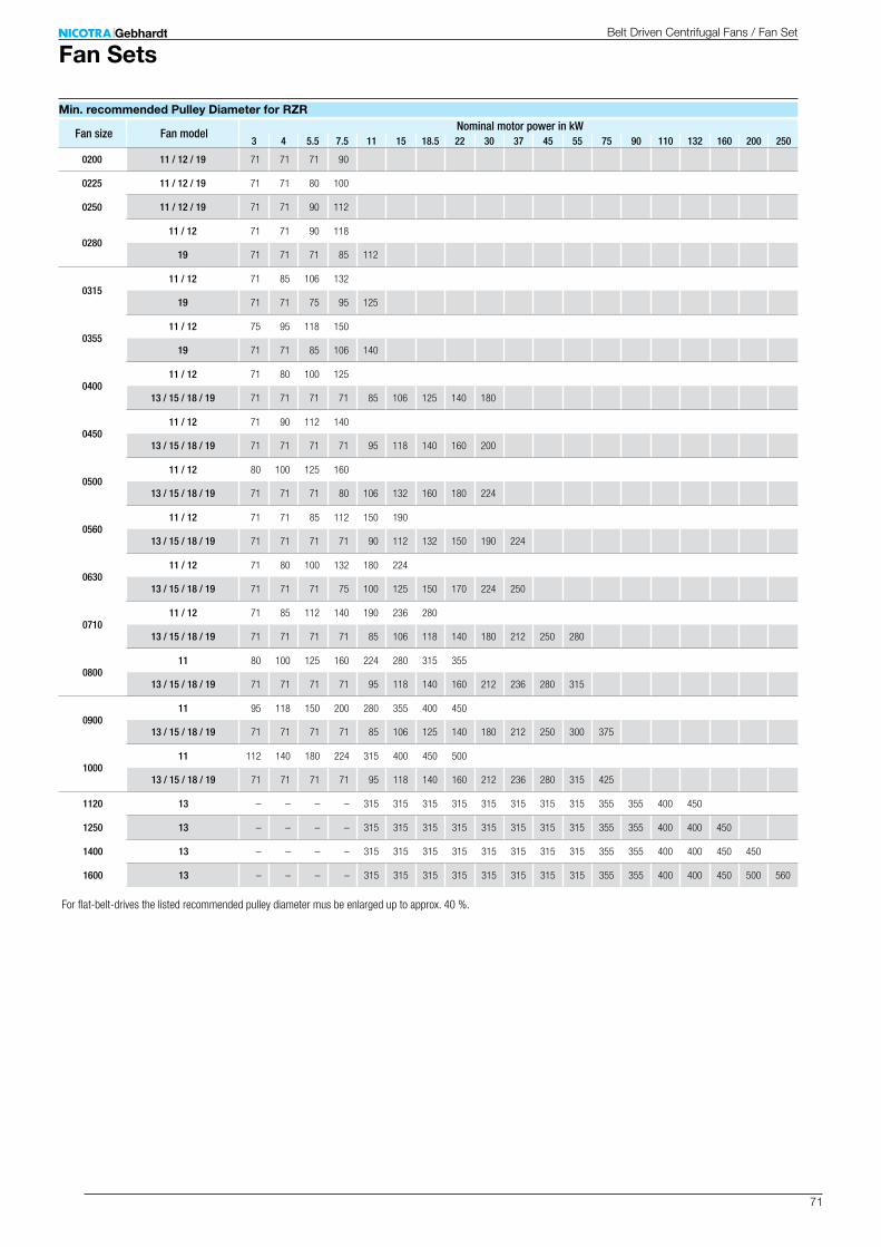
71
3 4 5.5 7.5 11 15 18.5 22 30 37 45 55 75 90 110 132 160 200 250
0200 11 / 12 / 19 71 71 71 90
0225 11 / 12 / 19 71 71 80 100
0250 11 / 12 / 19 71 71 90 112
028011 / 12 71 71 90 118
19 71 71 71 85 112
031511 / 12 71 85 106 132
19 71 71 75 95 125
035511 / 12 75 95 118 150
19 71 71 85 106 140
040011 / 12 71 80 100 125
13 / 15 / 18 / 19 71 71 71 71 85 106 125 140 180
045011 / 12 71 90 112 140
13 / 15 / 18 / 19 71 71 71 71 95 118 140 160 200
050011 / 12 80 100 125 160
13 / 15 / 18 / 19 71 71 71 80 106 132 160 180 224
056011 / 12 71 71 85 112 150 190
13 / 15 / 18 / 19 71 71 71 71 90 112 132 150 190 224
063011 / 12 71 80 100 132 180 224
13 / 15 / 18 / 19 71 71 71 75 100 125 150 170 224 250
071011 / 12 71 85 112 140 190 236 280
13 / 15 / 18 / 19 71 71 71 71 85 106 118 140 180 212 250 280
080011 80 100 125 160 224 280 315 355
13 / 15 / 18 / 19 71 71 71 71 95 118 140 160 212 236 280 315
090011 95 118 150 200 280 355 400 450
13 / 15 / 18 / 19 71 71 71 71 85 106 125 140 180 212 250 300 375
100011 112 140 180 224 315 400 450 500
13 / 15 / 18 / 19 71 71 71 71 95 118 140 160 212 236 280 315 425
1120 13 – – – – 315 315 315 315 315 315 315 315 355 355 400 450
1250 13 – – – – 315 315 315 315 315 315 315 315 355 355 400 400 450
1400 13 – – – – 315 315 315 315 315 315 315 315 355 355 400 400 450 450
1600 13 – – – – 315 315 315 315 315 315 315 315 355 355 400 400 450 500 560
Fan SetsBelt Driven Centrifugal Fans / Fan Set
Min. recommended Pulley Diameter for RZR
For flat-belt-drives the listed recommended pulley diameter mus be enlarged up to approx. 40 %.
Fan size Fan modelNominal motor power in kW
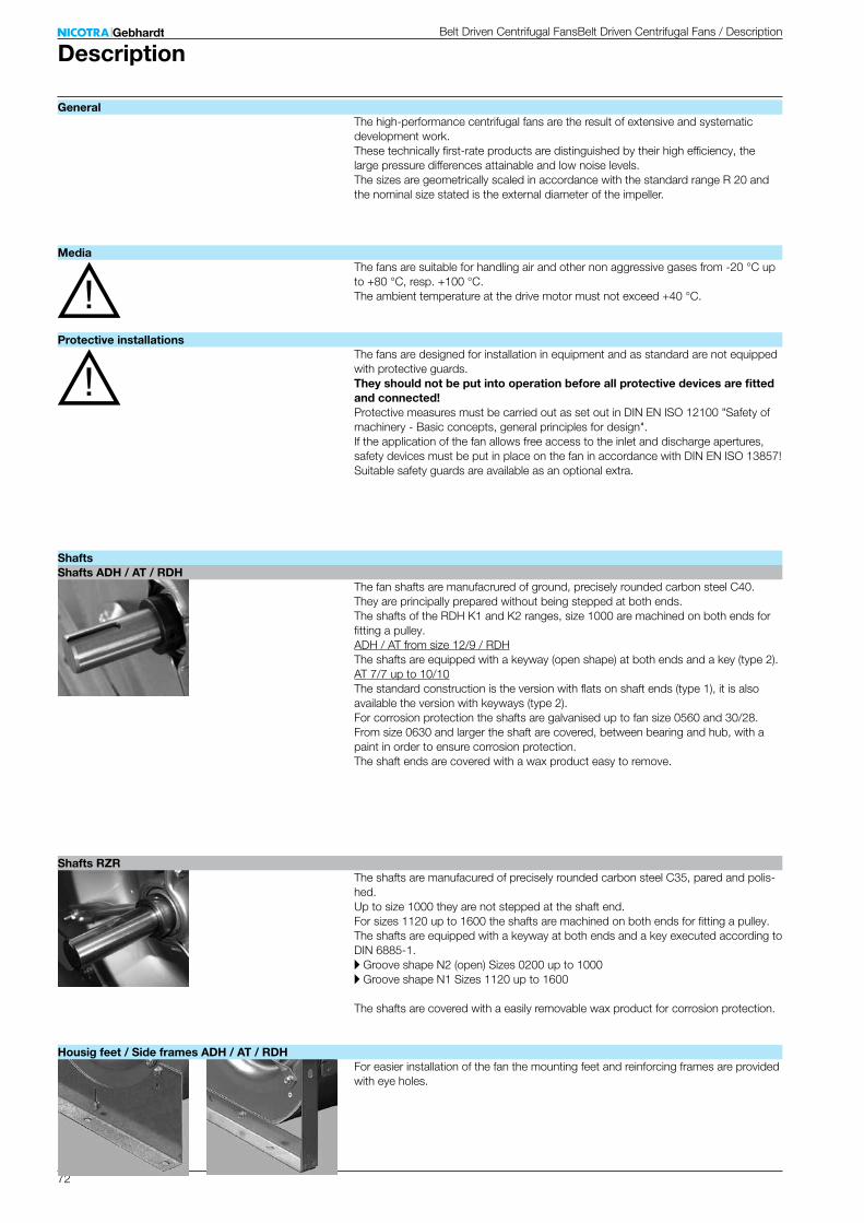
72
Belt Driven Centrifugal FansBelt Driven Centrifugal Fans / Description
The high-performance centrifugal fans are the result of extensive and systematic development work. These technically first-rate products are distinguished by their high efficiency, the large pressure differences attainable and low noise levels. The sizes are geometrically scaled in accordance with the standard range R 20 and the nominal size stated is the external diameter of the impeller.
The fans are suitable for handling air and other non aggressive gases from -20 °C up to +80 °C, resp. +100 °C. The ambient temperature at the drive motor must not exceed +40 °C.
The fans are designed for installation in equipment and as standard are not equipped with protective guards.They should not be put into operation before all protective devices are fitted and connected!Protective measures must be carried out as set out in DIN EN ISO 12100 "Safety of machinery - Basic concepts, general principles for design". If the application of the fan allows free access to the inlet and discharge apertures, safety devices must be put in place on the fan in accordance with DIN EN ISO 13857!Suitable safety guards are available as an optional extra.
The fan shafts are manufacrured of ground, precisely rounded carbon steel C40. They are principally prepared without being stepped at both ends. The shafts of the RDH K1 and K2 ranges, size 1000 are machined on both ends for fitting a pulley.ADH / AT from size 12/9 / RDH The shafts are equipped with a keyway (open shape) at both ends and a key (type 2).AT 7/7 up to 10/10 The standard construction is the version with flats on shaft ends (type 1), it is also available the version with keyways (type 2). For corrosion protection the shafts are galvanised up to fan size 0560 and 30/28. From size 0630 and larger the shaft are covered, between bearing and hub, with a paint in order to ensure corrosion protection. The shaft ends are covered with a wax product easy to remove.
The shafts are manufacured of precisely rounded carbon steel C35, pared and polis-hed. Up to size 1000 they are not stepped at the shaft end. For sizes 1120 up to 1600 the shafts are machined on both ends for fitting a pulley. The shafts are equipped with a keyway at both ends and a key executed according to DIN 6885-1.A Groove shape N2 (open) Sizes 0200 up to 1000A Groove shape N1 Sizes 1120 up to 1600
The shafts are covered with a easily removable wax product for corrosion protection.
For easier installation of the fan the mounting feet and reinforcing frames are provided with eye holes.
Description
General
Media
Protective installations
ShaftsShafts ADH / AT / RDH
Shafts RZR
Housig feet / Side frames ADH / AT / RDH

73
ADH E0 / ADH L ADH E2 / ADH R AT S / AT SC AT G2L / AT SC2 RDH E0 RDH E2 / RDH R
ADH E4 / ADH K AT AR / AT TIC / AT G2C RDH E4 / RDH K
ADH E6 / ADH K1 / ADH E7-0500 RDH E6 / RDH K1 / RDH E7-0500
ADH E7-0560; ADH K2-0630/-0800 AT G2C-C2 RDH E7-0560; RDH K2-0630/-0800
ADH K2-0900-1000 RDH K2-0900-1000 RDH X1 RDH X2
DescriptionBelt Driven Centrifugal FansBelt Driven Centrifugal Fans / Description
Maintenance free, self aligning radial insert ball bearings, mounted in pressed steel housing/strut assemblies with rubber interliners.
Monobloc pedestal cast iron pillow block bearings with relubrication nipple, mounted on a robust frame. Integrated, maintenance free self aligning radial ball bearings, fixed by eccentric clamp.
Pilow block cast iron bearings with relubrication nipple, mounted on a robust frame. Integrated self aligning radial ball bearings, fixed by conical sleeve and locknut.
Split-type plummer block bearings with relubrication nipple, mounted on a robust frame, integrated self ali-gning double row ball-bearings fixed by conical sleeve, lubricated with long life high performance grease.
Single piece plummer block housing, with grease nipple, mounted on robust pedestal, equipped with self aligning double row roller bearing, fixed to impeller shaft by a concentric shaft clamp, lubricated with long life high performance grease.
The twin fans up to size 0630 are equipped with one single shaft and 3 bearings. From size 0710 the two separate fans are connected by an elastic coupling. For the models G2K2 the bearings from size 0710 and larger are – due to different loads – of a different execu-tion inside compared to outside.
Twin Fans
Bearings ADH / AT / RDH
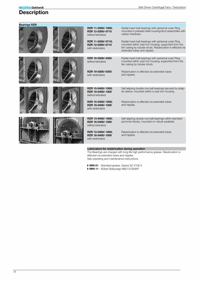
74
RZR 11-0200/-1000; RZR 12-0200/-0710
RZR 11-0200/-0710; RZR 12-0200/-0710
RZR 19-0200/-0355
RZR 19-0200/-0355
RZR 15-0400/-1000; RZR 19-0400/-1000
RZR 15-0400/-1000; RZR 19-0400/-1000
RZR 13-0400/-1600; RZR 18-0400/-1000
RZR 13-0400/-1600; RZR 18-0400/-1000
Radial insert ball bearings with spherical outer Ring mounted in pressed steel housing/strut assemblies with rubber interliners.
Radial insert ball bearings with spherical outer Ring mounted within cast iron housing, supported from the fan casing by tubular struts. Relubrication is effected via extended tubes and nipples.
Radial insert ball bearings with spherical outer Ring mounted within cast iron housing, supported from the fan casing by tubular struts.
Relubrication is effected via extended tubes and nipples.
Self aligning double row ball bearings secured by adap-ter sleeve, mounted within a cast iron housing.
Relubrication is effected via extended tubes and nipples.
Self aligning double row ball bearings within standard plummer blocks, mounted on robust pedestal.
Relubrication is effected via extended tubes and nipples.
The Bearings are charged with long life high performance grease. Relubrication is effected via extended tubes and nipples. See operating and maintenance instructions.
A IWN 01 - Standard grease, Gadus S2 V100 3A IWN 11 - Klüber-Staburags NBU12/300KP
DescriptionBelt Driven Centrifugal Fans / Description
Bearings RZR
Lubricators for relubrication during operation
(with relubricators)
(with relubricators)
(with relubricators)
(with relubricators)
(without lubricators)
(without lubricators)
(without lubricators)
(without lubricators)
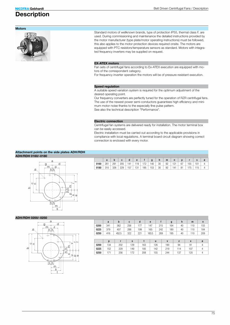
75
a b c d e f g h m n p r s ø0160 281 291 205 141 119 172 140 30 92 121 67 155 101 4
0180 310 326 229 157 131 195 153 30 92 141 81 175 115 4
ag d
m ph h
h hms
ø
ncb
fresp
mh
h
a b c d e f g h m n0200 341 362 256 177 147 215 164 40 110 155
0225 379 407 288 199 165 242 180 40 110 184
0250 416 452.5 322 221 183.5 269 195 40 110 209
ag d
m zh h
h hms
ø
ncb
rvpux
mhh
t
fe
p r s t u v z x ø0200 134 202 129 163 126 190 94 91 4
0225 152 229 149 185 142 219 114 107 4
0250 171 256 172 208 155 244 137 120 4
ADH/RDH 0160/-0180
ADH/RDH 0200/-0250
Standard motors of wellknown brands, type of protection IP55, thermal class F, are used. During commissioning and maintenance the detailed instructions provided by the motor manufacturer (type plate/motor operating instructions) must be followed, this also applies to the motor protection devices required onsite. The motors are equipped with PTC resistors/temperature sensors as standard. Motors with integra-ted frequency inverters may be supplied on request.
Fan sets of centrifugal fans according to Ex-ATEX execution are equipped with mo-tors of the correspondent category. For frequency inverter operation the motors will be of pressure resistant execution.
A suitable speed variation system is required for the optimum adjustment of the desired operating point. Our frequency converters are perfectly tuned for the operation of RZR centrifugal fans. The use of the newest power semi-conductors guarantees high efficiency and mini-mum motor noise thanks to the especially fine pulse pattern. See also the technical description "Performance".
Centrifugal fan systems are delivered ready for installation. The motor terminal box can be easily accessed. Electric installation must be carried out according to the applicable provisions in compliance with local regulations. A terminal board circuit diagram showing correct connection is enclosed with every motor.
DescriptionBelt Driven Centrifugal Fans / Description
Motors
EX-ATEX motors
Speed regulation
Electric connection
Attachment points on the side plates ADH/RDH
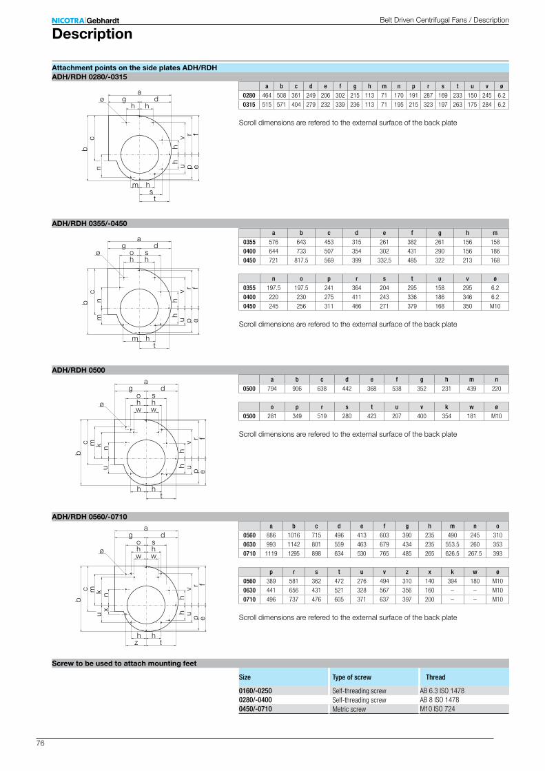
76
0160/-0250 AB 6.3 ISO 14780280/-0400 AB 8 ISO 14780450/-0710 M10 ISO 724
a b c d e f g h m n p r s t u v ø0280 464 508 361 249 206 302 215 113 71 170 191 287 169 233 150 245 6.2
0315 515 571 404 279 232 339 236 113 71 195 215 323 197 263 175 284 6.2
ag d
h h
m hs
øn
cb
rvpu
hh
tf
e
a b c d e f g h m0355 576 643 453 315 261 382 261 156 158
0400 644 733 507 354 302 431 290 156 186
0450 721 817.5 569 399 332.5 485 322 213 168
ag d
h h
m h
ø
mc
b
rvpu
hh
t
fe
o s
n
n o p r s t u v ø0355 197.5 197.5 241 364 204 295 158 295 6.2
0400 220 230 275 411 243 336 186 346 6.2
0450 245 256 311 466 271 379 168 350 M10
a b c d e f g h m n0500 794 906 638 442 368 538 352 231 439 220
ag d
w w
h h
ø
u
cb
rv
puh
h
t
fe
h h
n
o s
km
o p r s t u v k w ø0500 281 349 519 280 423 207 400 354 181 M10
a b c d e f g h m n o0560 886 1016 715 496 413 603 390 235 490 245 310
0630 993 1142 801 559 463 679 434 235 553.5 260 353
0710 1119 1295 898 634 530 765 485 265 626.5 267.5 393
p r s t u v z x k w ø0560 389 581 362 472 276 494 310 140 394 180 M10
0630 441 656 431 521 328 567 356 160 – – M10
0710 496 737 476 605 371 637 397 200 – – M10
ag d
w w
h h
ø
x
cb
rvpu
hh
t
fe
h h
n
o s
km
z
u
ADH/RDH 0280/-0315
ADH/RDH 0355/-0450
ADH/RDH 0500
ADH/RDH 0560/-0710
Size Type of screw Thread
Self-threading screwMetric screw
Self-threading screw
DescriptionBelt Driven Centrifugal Fans / Description
Attachment points on the side plates ADH/RDH
Screw to be used to attach mounting feet
Scroll dimensions are refered to the external surface of the back plate
Scroll dimensions are refered to the external surface of the back plate
Scroll dimensions are refered to the external surface of the back plate
Scroll dimensions are refered to the external surface of the back plate
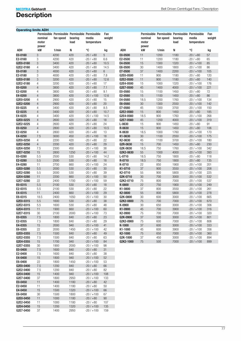
77
E0-0160 3 4200 420 -20 / +80 5E2-0160 3 4200 420 -20 / +80 6.6G2E0-0160 3 3400 420 -20 / +80 10.5G2E2-0160 4 3400 420 -20 / +80 14.5E0-0180 3 4000 420 -20 / +80 6E2-0180 3 4000 420 -20 / +80 7.8G2E0-0180 3 3200 420 -20 / +80 12.6G2E2-0180 4 3200 420 -20 / +80 17E0-0200 4 3800 420 -20 / +80 7.1E2-0200 4 3800 420 -20 / +80 9.1E4-0200 4 3800 420 -20 / +100 12.6G2E0-0200 4 2900 420 -20 / +80 15G2E2-0200 4 2900 420 -20 / +80 20E0-0225 4 3400 420 -20 / +80 8.5E2-0225 4 3400 420 -20 / +80 10.7E4-0225 4 3400 420 -20 / +100 14.5G2E0-0225 4 2600 420 -20 / +80 18G2E2-0225 4 2600 420 -20 / +80 24E0-0250 4 2800 420 -20 / +80 10.5E2-0250 4 2800 420 -20 / +80 13E4-0250 7.5 3000 450 -20 / +100 18G2E0-0250 4 2200 420 -20 / +80 22G2E2-0250 4 2200 420 -20 / +80 29G2E4-0250 7.5 2300 450 -20 / +100 38G2E7-0250 15 2800 1250 -20 / +100 44E0-0280 5.5 2500 530 -20 / +80 14.2E2-0280 5.5 2500 530 -20 / +80 18E4-0280 11 2700 660 -20 / +100 24G2E0-0280 5.5 2000 530 -20 / +80 30G2E2-0280 5.5 2000 530 -20 / +80 39G2E4-0280 11 2200 660 -20 / +100 50G2E7-0280 22 2400 1700 -20 / +100 59E0-0315 5.5 2100 530 -20 / +80 18E2-0315 5.5 2100 530 -20 / +80 22E4-0315 11 2400 660 -20 / +100 29E6-0315 18.5 2400 1050 -20 / +100 30G2E0-0315 5.5 1600 530 -20 / +80 38G2E2-0315 5.5 1600 530 -20 / +80 48G2E4-0315 11 1900 660 -20 / +100 60G2E7-0315 30 2100 2000 -20 / +100 73E0-0355 7.5 1800 840 -20 / +80 23E2-0355 7.5 1800 840 -20 / +80 29E4-0355 15 2000 940 -20 / +100 41E6-0355 22 2000 1450 -20 / +100 42G2E0-0355 7.5 1500 840 -20 / +80 49G2E2-0355 7.5 1500 840 -20 / +80 63G2E4-0355 15 1700 940 -20 / +100 84G2E7-0355 30 1900 2000 -20 / +100 98E0-0400 7.5 1600 840 -20 / +80 31E2-0400 7.5 1600 840 -20 / +80 38E4-0400 15 1800 940 -20 / +100 52E6-0400 22 1800 1450 -20 / +100 53G2E0-0400 7.5 1200 840 -20 / +80 66G2E2-0400 7.5 1200 840 -20 / +80 82G2E4-0400 15 1400 940 -20 / +100 108G2E7-0400 37 1800 2950 -20 / +100 133E0-0450 11 1400 1180 -20 / +80 42E2-0450 11 1400 1180 -20 / +80 50E4-0450 15 1500 1320 -20 / +100 66E6-0450 30 1500 1800 -20 / +100 67G2E0-0450 11 1000 1180 -20 / +80 90G2E2-0450 11 1000 1180 -20 / +80 107G2E4-0450 15 1200 1320 -20 / +100 135G2E7-0450 37 1400 2950 -20 / +100 159
E0-0500 11 1200 1180 -20 / +80 57E2-0500 11 1200 1180 -20 / +80 65E4-0500 15 1300 1320 -20 / +100 85E6-0500 30 1400 1800 -20 / +100 86E7-0500 37 1400 2200 -20 / +100 105G2E0-0500 11 900 1180 -20 / +80 120G2E2-0500 11 900 1180 -20 / +80 140G2E4-0500 15 1000 1320 -20 / +100 176G2E7-0500 45 1400 4000 -20 / +100 221E0-0560 15 1100 1450 -20 / +80 72E2-0560 15 1100 1450 -20 / +80 86E4-0560 18.5 1200 1760 -20 / +100 134E6-0560 30 1300 2550 -20 / +100 142E7-0560 45 1300 3700 -20 / +100 150G2E2-0560 15 800 1450 -20 / +80 185G2E4-0560 18.5 900 1760 -20 / +100 268G2E7-0560 45 1200 4000 -20 / +100 319L-0630 15 900 1450 -20 / +80 91R-0630 15 900 1450 -20 / +80 106K-0630 18.5 1000 1760 -20 / +100 170K1-0630 30 1100 2550 -20 / +100 175K2-0630 45 1100 3700 -20 / +100 180G2R-0630 15 700 1450 -20 / +80 230G2K-0630 18.5 750 1760 -20 / +100 342G2K2-0630 55 1000 4000 -20 / +100 393L-0710 18.5 750 1800 -20 / +80 118R-0710 18.5 750 1800 -20 / +80 135K-0710 22 850 1900 -20 / +100 201K1-0710 37 900 3550 -20 / +100 208K2-0710 55 900 5800 -20 / +100 225G2K-0710 30 700 3000 -20 / +100 532G2K2-0710 75 800 7000 -20 / +100 537K-0800 22 750 1900 -20 / +100 249K1-0800 37 800 3550 -20 / +100 261K2-0800 55 800 5800 -20 / +100 278G2K-0800 30 600 3000 -20 / +100 665G2K2-0800 75 700 7000 -20 / +100 670K-0900 30 650 3000 -20 / +100 306K1-0900 45 700 3900 -20 / +100 316K2-0900 75 700 7000 -20 / +100 320G2K-0900 37 500 3000 -20 / +100 801G2K2-0900 75 600 7000 -20 / +100 806K-1000 37 600 3000 -20 / +100 333K1-1000 45 600 3900 -20 / +100 356K2-1000 75 650 7000 -20 / +100 360G2K-1000 37 450 3000 -20 / +100 894G2K2-1000 75 500 7000 -20 / +100 899
kWADH 1/min N °C kg kWADH 1/min N °C kg
Permissible nominal motor power
Permissible fan speed
Permissible bearing load
Permissible media temperature
Fan weight
Permissible nominal motor power
Permissible fan speed
Permissible bearing load
Permissible media temperature
Fan weight
DescriptionBelt Driven Centrifugal Fans / Description
Operating limits ADH
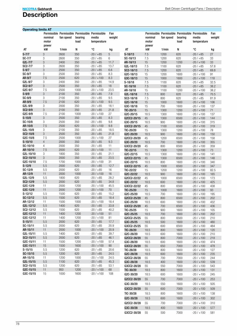
78
S-7/7 3 2600 350 -20 / +85 5SC-7/7 3 2600 350 -20 / +85 6G2L-7/7 3 2400 350 -20 / +85 11.7SC2-7/7 3 2600 350 -20 / +85 13.7S-9/7 3 2500 350 -20 / +85 6.6SC-9/7 3 2500 350 -20 / +85 8.3AR-9/7 7.5 2500 620 -20 / +100 8.3G2L-9/7 3 2400 350 -20 / +85 14.9SC2-9/7 3 2500 350 -20 / +85 18G2C-9/7 7.5 2500 1000 -20 / +100 23.5S-9/9 3 2100 350 -20 / +85 7.9SC-9/9 3 2100 350 -20 / +85 9.5AR-9/9 7.5 2100 620 -20 / +100 9.5G2L-9/9 3 2000 350 -20 / +85 18.1SC2-9/9 3 2100 350 -20 / +85 21.8G2C-9/9 7.5 2100 1000 -20 / +100 27S-10/8 3 2500 350 -20 / +85 8.3SC-10/8 3 2500 350 -20 / +85 9.8AR-10/8 7.5 2500 620 -20 / +100 9.8G2L-10/8 3 2100 350 -20 / +85 18.5SC2-10/8 3 2500 350 -20 / +85 21.8G2C-10/8 7.5 2500 1000 -20 / +100 27S-10/10 4 2000 350 -20 / +85 9.3SC-10/10 4 2000 350 -20 / +85 11AR-10/10 7.5 2000 620 -20 / +100 11G2L-10/10 3 1800 350 -20 / +85 21.1SC2-10/10 3 2000 350 -20 / +85 23.5G2C-10/10 7.5 1700 1000 -20 / +100 31S-12/9 5.5 2000 620 -20 / +85 12.7SC-12/9 5.5 2000 620 -20 / +85 16AR-12/9 11 2000 1000 -20 / +100 16G2L-12/9 5.5 1800 620 -20 / +85 28.2SC2-12/9 5.5 2000 620 -20 / +85 34.8G2C-12/9 11 2000 1200 -20 / +100 45.5G3C-12/9 11 2000 1200 -20 / +100 70S-12/12 5.5 1500 620 -20 / +85 15.2SC-12/12 5.5 1500 620 -20 / +85 18.4AR-12/12 11 1500 1000 -20 / +100 18.4G2L-12/12 5.5 1400 620 -20 / +85 33.8SC2-12/12 5.5 1500 620 -20 / +85 40.2G2C-12/12 11 1400 1200 -20 / +100 51G3C-12/12 11 1400 1200 -20 / +100 81S-15/11 5.5 2000 620 -20 / +85 17.7SC-15/11 5.5 2000 620 -20 / +85 20.9AR-15/11 11 2000 1000 -20 / +100 20.9G2L-15/11 5.5 1400 620 -20 / +85 39.7SC2-15/11 5.5 2000 620 -20 / +85 46.1G2C-15/11 11 1500 1200 -20 / +100 57.4G3C-15/11 15 1500 1600 -20 / +100 90S-15/15 5.5 1200 620 -20 / +85 20.6SC-15/15 5.5 1200 620 -20 / +85 24.5AR-15/15 11 1200 1000 -20 / +100 24.5G2L-15/15 5.5 1100 620 -20 / +85 45.3SC2-15/15 5.5 1200 620 -20 / +85 53.1G2C-15/15 11 950 1200 -20 / +100 68G3C-15/15 15 1000 1600 -20 / +100 108
S-18/13 7.5 1200 620 -20 / +85 27SC-18/13 7.5 1200 620 -20 / +85 33AR-18/13 15 1200 1200 -20 / +100 33G2L-18/13 7.5 1100 620 -20 / +85 57.8SC2-18/13 7.5 1200 620 -20 / +85 69.8G2C-18/13 15 1200 1600 -20 / +100 91G3C-18/13 15 1000 1600 -20 / +100 118S-18/18 7.5 1100 620 -20 / +85 32.5SC-18/18 7.5 1100 620 -20 / +85 38.2AR-18/18 15 1100 1200 -20 / +100 38.2G2L-18/18 7.5 800 620 -20 / +85 70.5SC2-18/18 7.5 800 620 -20 / +85 81.9G2C-18/18 15 1000 1600 -20 / +100 106G3C-18/18 15 700 1600 -20 / +100 137TIC-20/15 15 1300 1200 -20 / +100 71G2C-20/15 18.5 1300 1600 -20 / +100 137G2CC2-20/15 45 1300 6500 -20 / +100 144G3C-20/15 18.5 900 1600 -20 / +100 315G3CC2-20/15 45 1100 6500 -20 / +100 319TIC-20/20 15 1300 1200 -20 / +100 78G2C-20/20 18.5 900 1600 -20 / +100 150G2CC2-20/20 45 1200 6500 -20 / +100 158G3C-20/20 18.5 700 1600 -20 / +100 355G3CC2-20/20 45 800 6500 -20 / +100 359TIC-22/15 15 1300 1200 -20 / +100 73G2C-22/15 18.5 1300 1600 -20 / +100 141G2CC2-22/15 45 1300 6500 -20 / +100 148G3C-22/15 18.5 800 1600 -20 / +100 340G3CC2-22/15 45 1000 6500 -20 / +100 347TIC-22/22 15 1200 1200 -20 / +100 82.5G2C-22/22 18.5 900 1600 -20 / +100 165G2CC2-22/22 45 1000 6500 -20 / +100 173G3C-22/22 18.5 600 1600 -20 / +100 425G3CC2-22/22 45 800 6500 -20 / +100 438TIC-25/20 15 1000 1600 -20 / +100 93G2C-25/20 18.5 700 1600 -20 / +100 195G2CC2-25/20 45 800 6500 -20 / +100 202G3C-25/20 18.5 600 1600 -20 / +100 432G3CC2-25/20 45 700 6500 -20 / +100 436TIC-25/25 15 900 1600 -20 / +100 105G2C-25/25 18.5 700 1600 -20 / +100 202G2CC2-25/25 55 800 6500 -20 / +100 210G3C-25/25 18.5 500 1600 -20 / +100 480G3CC2-25/25 55 600 6500 -20 / +100 484TIC-28/20 18.5 800 1600 -20 / +100 120G2C-28/20 18.5 600 1600 -20 / +100 210G2CC2-28/20 55 800 7000 -20 / +100 218G3C-28/20 18.5 600 1600 -20 / +100 474G3CC2-28/20 55 650 7000 -20 / +100 478TIC-28/28 18.5 800 1600 -20 / +100 127G2C-28/28 18.5 600 1600 -20 / +100 235G2CC2-28/28 55 700 7000 -20 / +100 244G3C-28/28 18.5 400 1600 -20 / +100 539G3CC2-28/28 55 550 7000 -20 / +100 543TIC-30/20 18.5 800 1600 -20 / +100 131G2C-30/20 18.5 600 1600 -20 / +100 245
G2CC2-30/20 55 700 7000 -20 / +100 253
G3C-30/20 18.5 550 1600 -20 / +100 505
G3CC2-30/20 55 600 7000 -20 / +100 509
TIC-30/28 18.5 800 1600 -20 / +100 138
G2C-30/28 18.5 600 1600 -20 / +100 302
G2CC2-30/28 55 700 7000 -20 / +100 310
G3C-30/28 18.5 400 1600 -20 / +100 577
G3CC2-30/28 55 500 7000 -20 / +100 581
kWAT 1/min N °C kg kWAT 1/min N °C kg
Permissible nominal motor power
Permissible fan speed
Permissible bearing load
Permissible media temperature
Fan weight
Permissible nominal motor power
Permissible fan speed
Permissible bearing load
Permissible media temperature
Fan weight
DescriptionBelt Driven Centrifugal Fans / Description
Operating limits AT

79
kWRDH 1/min N °C kg kWRDH 1/min N °C kg
E0-0180 2.2 6800 420 -20 / +80 5.3E2-0180 2.2 6800 420 -20 / +80 7.1E0-0200 3 6000 420 -20 / +80 6.6E2-0200 3 6000 420 -20 / +80 8.5E4-0200 3 6800 420 -20 / +100 11.8E0-0225 4 5800 420 -20 / +80 7.8E2-0225 4 5800 420 -20 / +80 9.9E4-0225 4 6000 420 -20 / +100 13.6E0-0250 4 4600 420 -20 / +80 13.3E2-0250 4 4600 420 -20 / +80 15.7E4-0250 5.5 5400 450 -20 / +100 21G2E4-0250 5.5 2900 450 -20 / +100 46G2E7-0250 7.5 3500 660 -20 / +100 49E0-0280 5.5 4000 530 -20 / +80 17.8E2-0280 5.5 4000 530 -20 / +80 21E4-0280 7.5 4700 660 -20 / +100 28G2E4-0280 5.5 3000 660 -20 / +100 61G2E7-0280 11 3400 940 -20 / +100 65E0-0315 5.5 3500 530 -20 / +80 21E2-0315 5.5 3500 530 -20 / +80 25E4-0315 7.5 4100 660 -20 / +100 32E6-0315 11 4500 1050 -20 / +100 34G2E4-0315 5.5 2200 660 -20 / +100 70G2E7-0315 11 3300 1320 -20 / +100 79E0-0355 7.5 3300 840 -20 / +80 29E2-0355 7.5 3300 840 -20 / +80 34E4-0355 11 3800 940 -20 / +100 46E6-0355 15 4000 1450 -20 / +100 47G2E4-0355 7.5 2000 940 -20 / +100 104G2E7-0355 11 2600 1320 -20 / +100 109E0-0400 7.5 2700 840 -20 / +80 36E2-0400 7.5 2700 840 -20 / +80 42E4-0400 15 3100 940 -20 / +100 57E6-0400 22 3500 1450 -20 / +100 58G2E4-0400 7.5 1600 940 -20 / +100 126G2E7-0400 18.5 2800 1760 -20 / +100 144E0-0450 11 2500 1180 -20 / +80 50E2-0450 11 2500 1180 -20 / +80 57E4-0450 15 2800 1320 -20 / +100 73E6-0450 30 3200 1800 -20 / +100 75G2E4-0450 11 1400 1320 -20 / +100 160G2E7-0450 18.5 2200 1760 -20 / +100 176E0-0500 11 2100 1180 -20 / +80 62E2-0500 11 2100 1180 -20 / +80 70E4-0500 15 2350 1320 -20 / +100 90E6-0500 30 2650 1800 -20 / +100 92E7-0500 37 2800 2200 -20 / +100 110G2E4-0500 11 1200 1320 -20 / +100 197G2E7-0500 30 2200 3000 -20 / +100 235E0-0560 15 1950 1450 -20 / +80 79E2-0560 15 1950 1450 -20 / +80 92E4-0560 18.5 2100 1760 -20 / +100 141E6-0560 30 2400 2550 -20 / +100 148E7-0560 37 2600 3700 -20 / +100 153G2E4-0560 11 1100 1760 -20 / +100 301G2E7-0560 30 1900 3000 -20 / +100 336R-0630 15 1600 1450 -20 / +80 119K-0630 18.5 1700 1760 -20 / +100 173K1-0630 30 2000 2550 -20 / +100 180K2-0630 45 2300 3700 -20 / +100 185G2K-0630 15 1000 1760 -20 / +100 370G2K2-0630 37 1400 3000 -20 / +100 408
R-0710 15 1300 1800 -20 / +80 165K-0710 22 1500 1900 -20 / +100 220K1-0710 37 1700 3550 -20 / +100 240K2-0710 55 2000 5800 -20 / +100 250G2K-0710 30 1400 3000 -20 / +100 580G2K2-0710 75 1700 7000 -20 / +100 586K-0800 22 1200 1900 -20 / +100 270K1-0800 37 1400 3550 -20 / +100 297K2-0800 55 1650 5800 -20 / +100 305G2K-0800 30 1150 3000 -20 / +100 747G2K2-0800 75 1400 7000 -20 / +100 753K-0900 30 1100 3000 -20 / +100 343K1-0900 45 1250 3900 -20 / +100 355K2-0900 75 1500 7000 -20 / +100 375G2K-0900 37 1000 3000 -20 / +100 883G2K2-0900 75 1100 7000 -20 / +100 889K-1000 37 1000 3000 -20 / +100 415K1-1000 45 1000 3900 -20 / +100 430K2-1000 75 1300 7000 -20 / +100 450G2K-1000 37 800 3000 -20 / +100 1048G2K2-1000 75 800 7000 -20 / +100 1054X1-1120 55 900 8000 -20 / +100 610X2-1120 110 1170 8000 -20 / +100 890X1-1250 75 800 8000 -20 / +100 950X2-1250 132 1050 10000 -20 / +100 1140X1-1400 90 720 9000 -20 / +100 1370X2-1400 160 930 12500 -20 / +100 1390
Permissible nominal motor power
Permissible fan speed
Permissible bearing load
Permissible media temperature
Fan weight
Permissible nominal motor power
Permissible fan speed
Permissible bearing load
Permissible media temperature
Fan weight
DescriptionBelt Driven Centrifugal Fans / Description
Operating limits RDH

80
kWRZR 1/min N °C kg kWRZR 1/min N °C kg
11-0200 7.5 7490 480 -20 / +80 1112-0200 7.5 7490 480 -20 / +80 1219-0200 7.5 7490 480 -20 / +80 1311-0225 7.5 6640 500 -20 / +80 1312-0225 7.5 6640 500 -20 / +80 1519-0225 7.5 6640 500 -20 / +80 1611-0250 7.5 5250 540 -20 / +80 1512-0250 7.5 5250 540 -20 / +80 1719-0250 7.5 5970 540 -20 / +80 1711-0280 7.5 5235 630 -20 / +80 2012-0280 7.5 5235 630 -20 / +80 2319-0280 11 5300 850 -20 / +80 2311-0315 7.5 4418 660 -20 / +80 2412-0315 7.5 4418 660 -20 / +80 2719-0315 11 4730 910 -20 / +80 2811-0355 7.5 3200 720 -20 / +80 3312-0355 7.5 3200 720 -20 / +80 3619-0355 11 4187 950 -20 / +80 3911-0400 7.5 3027 1020 -20 / +80 4312-0400 7.5 3027 1020 -20 / +80 4915-0400 30 3600 1970 -20 / +80 6119-0400 30 3600 1970 -20 / +80 6618-0400 30 3600 1970 -20 / +80 7013-0400 30 3600 1970 -20 / +80 7511-0450 7.5 2504 1080 -20 / +80 5412-0450 7.5 2504 1080 -20 / +80 6015-0450 30 3360 2000 -20 / +80 7319-0450 30 3360 2000 -20 / +80 8218-0450 30 3360 2000 -20 / +80 8313-0450 30 3360 2000 -20 / +80 9211-0500 7.5 2050 1140 -20 / +80 6512-0500 7.5 2050 1140 -20 / +80 7215-0500 30 2920 2040 -20 / +80 9419-0500 30 2920 2040 -20 / +80 10518-0500 30 2920 2040 -20 / +80 10513-0500 30 2920 2040 -20 / +80 11611-0560 15 2205 1830 -20 / +80 10312-0560 15 2205 1830 -20 / +80 10915-0560 37 2400 2950 -20 / +80 12519-0560 37 2400 2950 -20 / +80 13618-0560 37 2490 2950 -20 / +80 14013-0560 37 2490 2950 -20 / +80 15111-0630 15 1838 1960 -20 / +80 12412-0630 15 1838 1960 -20 / +80 13215-0630 37 1880 3000 -20 / +80 14919-0630 37 1880 3000 -20 / +80 16218-0630 37 2380 3000 -20 / +80 16713-0630 37 2380 3000 -20 / +80 18011-0710 18.5 1627 2080 -20 / +80 17712-0710 18.5 1627 2080 -20 / +80 19415-0710 55 2000 4400 -20 / +80 20119-0710 55 2000 4400 -20 / +80 22518-0710 55 2120 4400 -20 / +80 23013-0710 55 2120 4400 -20 / +80 25411-0800 22 1300 2150 -20 / +80 25015-0800 55 1470 4500 -20 / +80 25019-0800 55 1470 4500 -20 / +80 28018-0800 55 1700 4500 -20 / +80 28913-0800 55 1700 4500 -20 / +80 31911-0900 22 1000 2180 -20 / +80 35815-0900 75 1430 6000 -20 / +80 35819-0900 75 1430 6000 -20 / +80 396
18-0900 75 1540 6000 -20 / +80 40913-0900 75 1540 6000 -20 / +80 44711-1000 22 800 2200 -20 / +80 41615-1000 75 1140 6200 -20 / +80 41619-1000 75 1140 6200 -20 / +80 46218-1000 75 1400 6200 -20 / +80 47113-1000 75 1400 6200 -20 / +80 51713-1120 132 1220 10000 -20 / +80 71013-1250 160 1100 15000 -20 / +80 110013-1400 200 1000 20000 -20 / +80 139013-1600 250 860 20000 -20 / +80 1870
Permissible nominal motor power
Permissible fan speed
Permissible bearing load
Permissible media temperature
Fan weight
Permissible nominal motor power
Permissible fan speed
Permissible bearing load
Permissible media temperature
Fan weight
DescriptionBelt Driven Centrifugal Fans / Description
Operating limits RZR
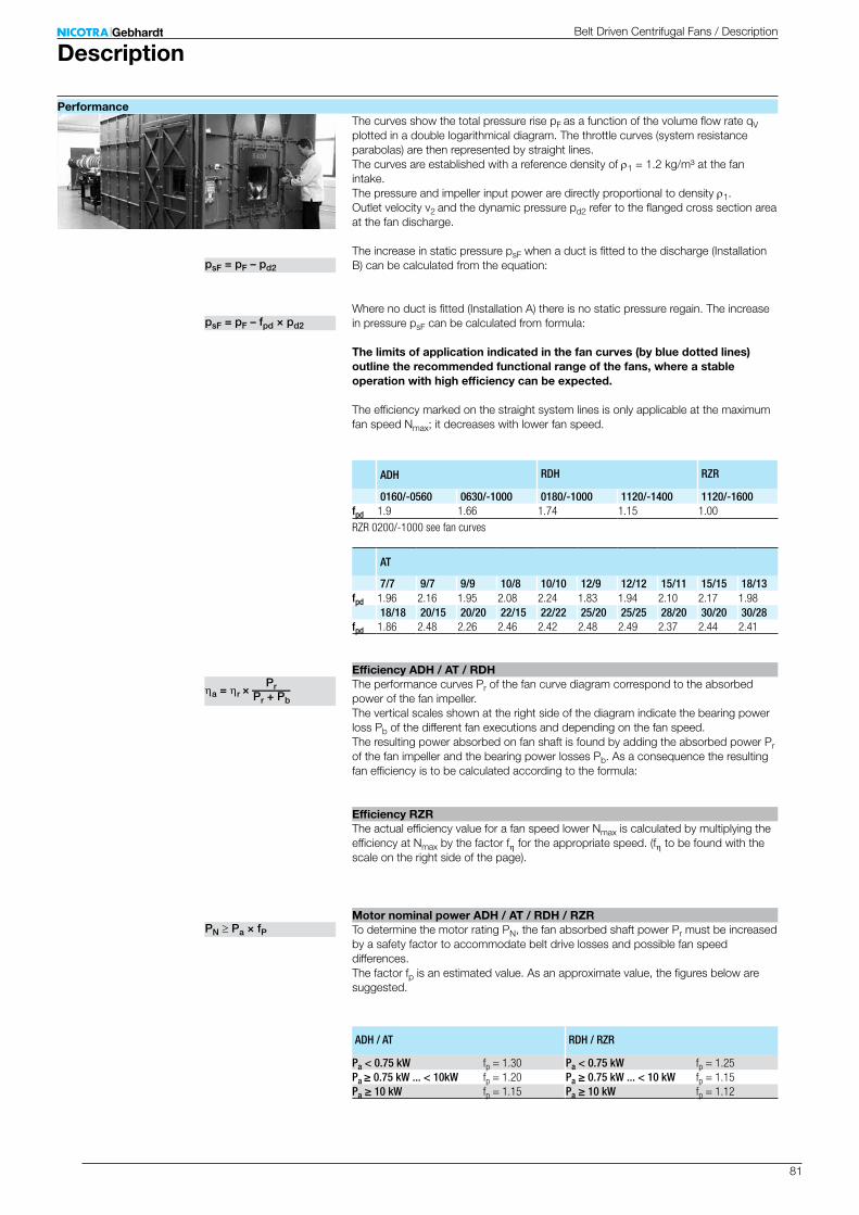
81
ADH RDH RZR
0160/-0560 0630/-1000 0180/-1000 1120/-1400 1120/-1600fpd 1.9 1.66 1.74 1.15 1.00
AT
7/7 9/7 9/9 10/8 10/10 12/9 12/12 15/11 15/15 18/13fpd 1.96 2.16 1.95 2.08 2.24 1.83 1.94 2.10 2.17 1.98
18/18 20/15 20/20 22/15 22/22 25/20 25/25 28/20 30/20 30/28fpd 1.86 2.48 2.26 2.46 2.42 2.48 2.49 2.37 2.44 2.41
ADH / AT RDH / RZR
Pa < 0.75 kW fp = 1.30 Pa < 0.75 kW fp = 1.25Pa ≥ 0.75 kW ... < 10kW fp = 1.20 Pa ≥ 0.75 kW ... < 10 kW fp = 1.15Pa ≥ 10 kW fp = 1.15 Pa ≥ 10 kW fp = 1.12
PN Pa × fP
a = r × — PrPr + Pb
psF = pF – pd2
psF = pF – fpd × pd2
DescriptionBelt Driven Centrifugal Fans / Description
The curves show the total pressure rise pF as a function of the volume flow rate qV plotted in a double logarithmical diagram. The throttle curves (system resistance parabolas) are then represented by straight lines. The curves are established with a reference density of r1 = 1.2 kg/m³ at the fan intake. The pressure and impeller input power are directly proportional to density r1. Outlet velocity v2 and the dynamic pressure pd2 refer to the flanged cross section area at the fan discharge. The increase in static pressure psF when a duct is fitted to the discharge (Installation B) can be calculated from the equation: Where no duct is fitted (Installation A) there is no static pressure regain. The increase in pressure psF can be calculated from formula:
The limits of application indicated in the fan curves (by blue dotted lines) outline the recommended functional range of the fans, where a stable operation with high efficiency can be expected.
The efficiency marked on the straight system lines is only applicable at the maximum fan speed Nmax; it decreases with lower fan speed.
The performance curves Pr of the fan curve diagram correspond to the absorbed power of the fan impeller. The vertical scales shown at the right side of the diagram indicate the bearing power loss Pb of the different fan executions and depending on the fan speed. The resulting power absorbed on fan shaft is found by adding the absorbed power Pr of the fan impeller and the bearing power losses Pb. As a consequence the resulting fan efficiency is to be calculated according to the formula:
The actual efficiency value for a fan speed lower Nmax is calculated by multiplying the efficiency at Nmax by the factor fh for the appropriate speed. (fh to be found with the scale on the right side of the page).
To determine the motor rating PN, the fan absorbed shaft power Pr must be increased by a safety factor to accommodate belt drive losses and possible fan speed differences. The factor fp is an estimated value. As an approximate value, the figures below are suggested.
RZR 0200/-1000 see fan curves
Performance
Efficiency ADH / AT / RDH
Efficiency RZR
Motor nominal power ADH / AT / RDH / RZR
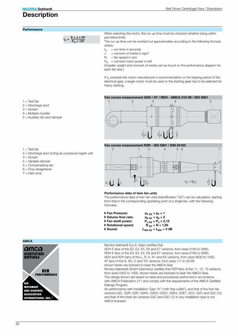
82
tA =—8 × J × N²PN × 106
pe6 p
1 4 532
pe4
t1tapapopsF
qV = f(po)
1 3 4 5 6 72
DescriptionBelt Driven Centrifugal Fans / Description
When selecting the motor, the run up time must be checked whether being within permitted limits. The run up time can be worked out approximately according to the following formula: where:tA = run time in secondsJ = moment of inertia in kgm²N = fan speed in rpmPN = nominal motor power in kW(Impeller weight and moment of inertia can be found on the performance diagram for each fan size.) If tA exceeds the motor manufacturer‘s recommendation or the tripping period of the electrical gear, a larger motor must be used or the starting gear has to be selected for heavy starting.
1 = Test fan2 = Discharge duct3 = Screen4 = Multiple nozzles5 = Auxiliary fan and damper
1 = Test fan2 = Discharge duct acting as a pressure regain unit3 = Screen4 = Variable damper5 = Compensating fan6 = Flow straightener7 = Inlet cone
Performance data of twin fan unitsThe performance data of twin fan units (Identification "G2") can be calculated, starting from that in the corresponding operating point of a single fan, with the following formulas:
A Fan Pressure: pF G2 = pF × 1A Volume flow rate: qV G2 = qV × 2A Fan shaft power: Pa G2 = Pa × 2,15A Rotational speed: N G2 = N × 1,05A Sound: LWA G2 = LWA + 3 dB
Nicotra Gebhardt S.p.A. (Italy) certifies that ADH E fans of the E0, E2, E4, E6 and E7 versions, from sizes 0160 to 0560, RDH E fans of the E0, E2, E4, E6 and E7 versions, from sizes 0180 to 0560, ADH and RDH fans of the L, R, K, K1 and K2 versions, from sizes 0630 to 1000, AT fans of the S, SC, C and TIC versions, from sizes 7/7 to 30/28, shown herein are licensed to bear the AMCA Seal.Nicotra Gebhardt GmbH (Germany) certifies that RZR fans of the 11, 12, 15 versions, from sizes 0355 to 1000, shown herein are licensed to bear the AMCA Seal. The ratings shown are based on tests and procedures performed in accordance with AMCA Publication 211 and comply with the requirements of the AMCA Certified Ratings Program. Air performance with Installation Type “A” (“with free outlet”), and that of the twin fan versions G2L, G2R, G2K, G2K2, G2E0, G2E2, G2E4, G2E7, SC2, G2C and G2C-C2, and that of the triple fan versions G3C and G3C-C2 in any installation type is not AMCA licensed.
Performance
Fan curves measurement ADH / AT / RDH - AMCA 210-99 / ISO 5801
Fan curves measurement RZR - ISO 5801 / DIN 24163
AMCA
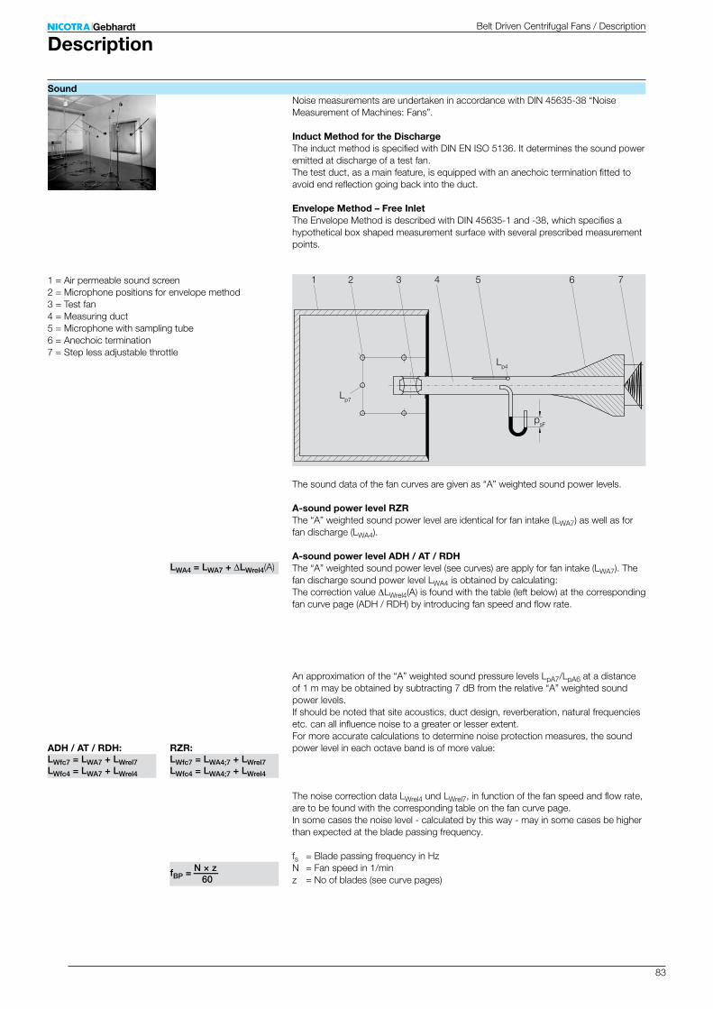
83
Lp7
Lp4
1 2 3 4 5 6 7
psF
LWA4 = LWA7 + LWrel4(A)
fBP = —N × z 60
ADH / AT / RDH: RZR:LWfc7 = LWA7 + LWrel7LWfc4 = LWA7 + LWrel4
LWfc7 = LWA4;7 + LWrel7LWfc4 = LWA4;7 + LWrel4
DescriptionBelt Driven Centrifugal Fans / Description
Noise measurements are undertaken in accordance with DIN 45635-38 “Noise Measurement of Machines: Fans”.
Induct Method for the DischargeThe induct method is specified with DIN EN ISO 5136. It determines the sound power emitted at discharge of a test fan. The test duct, as a main feature, is equipped with an anechoic termination fitted to avoid end reflection going back into the duct.
Envelope Method – Free InletThe Envelope Method is described with DIN 45635-1 and -38, which specifies a hypothetical box shaped measurement surface with several prescribed measurement points.
1 = Air permeable sound screen2 = Microphone positions for envelope method3 = Test fan4 = Measuring duct5 = Microphone with sampling tube6 = Anechoic termination7 = Step less adjustable throttle
The sound data of the fan curves are given as “A” weighted sound power levels.
A-sound power level RZRThe “A” weighted sound power level are identical for fan intake (LWA7) as well as for fan discharge (LWA4).
A-sound power level ADH / AT / RDHThe “A” weighted sound power level (see curves) are apply for fan intake (LWA7). The fan discharge sound power level LWA4 is obtained by calculating: The correction value DLWrel4(A) is found with the table (left below) at the corresponding fan curve page (ADH / RDH) by introducing fan speed and flow rate.
Sound
An approximation of the “A” weighted sound pressure levels LpA7/LpA6 at a distance of 1 m may be obtained by subtracting 7 dB from the relative “A” weighted sound power levels. If should be noted that site acoustics, duct design, reverberation, natural frequencies etc. can all influence noise to a greater or lesser extent. For more accurate calculations to determine noise protection measures, the sound power level in each octave band is of more value: The noise correction data LWrel4 und LWrel7, in function of the fan speed and flow rate, are to be found with the corresponding table on the fan curve page. In some cases the noise level - calculated by this way - may in some cases be higher than expected at the blade passing frequency.
fs = Blade passing frequency in HzN = Fan speed in 1/minz = No of blades (see curve pages)
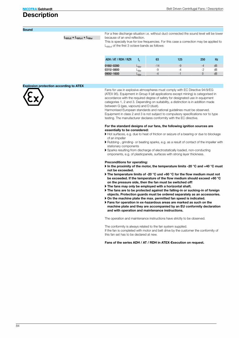
84
ADH / AT / RDH / RZR fc 63 125 250 Hz
0160/-0280 LWer -14 -9 -4 dB0315/-0800 LWer -9 -4 -2 dB0900/-1600 LWer -4 -1 0 dB
LWfc6 = LWfc4 + LWer
DescriptionBelt Driven Centrifugal Fans / Description
SoundFor a free discharge situation i.e. without duct connected the sound level will be lower because of an end reflection. This is specially true for low frequencies. For this case a correction may be applied to LWfc4 of the first 3 octave bands as follows:
Fans for use in explosive atmospheres must comply with EC Directive 94/9/EG (ATEX 95). Equipment in Group II (all applications except mining) is categorised in accordance with the required degree of safety for designated use in equipment categories 1, 2 and 3. Depending on suitability, a distinction is in addition made between G (gas, vapours) and D (dust). Harmonised European standards and national guidelines must be observed. Equipment in class 2 and 3 is not subject to compulsory specifications nor to type testing. The manufacturer declares conformity with the EC directive.
For the standard designs of our fans, the following ignition sources are essentially to be considered:A Hot surfaces, e.g. due to heat of friction or seizure of a bearing or due to blockage
of an impellerA Rubbing-, grinding- or beating sparks, e.g. as a result of contact of the impeller with
stationary componentsA Sparks resulting from discharge of electrostatically loaded, non-conducting
omponents, e.g. of plasticpanels, surfaces with strong layer thickness.
Preconditions for operating:A In the proximity of the motor, the temperature limits -20 °C and +40 °C must
not be exceeded.A The temperature limits of -20 °C und +60 °C for the flow medium must not
be exceeded. If the temperature of the flow medium should exceed +60 °C on the pressure side, then the fan must be switched off!
A The fans may only be employed with a horizontal shaft.A The fans are to be protected against the falling-in or sucking-in of foreign
objects. Protection guards must be ordered separately as an accessories.A On the machine plate the max. permitted fan speed is indicated.A Fans for operation in ex-hazardous areas are marked as such on the
machine plate and they are accompanied by an EU conformity declaration and with operation and maintenance instructions.
The operation and maintenance instructions have strictly to be observed. The conformity is always related to the fan system supplied. If the fan is completed with motor and belt drive by the customer the conformity of this fan set has to be declared at new.
Fans of the series ADH / AT / RDH in ATEX-Execution on request.
Explosion protection according to ATEX

85
kWRZR 1/min kW
11-0200-2G 6513 4.7 5.512-0200-2G 6513 4.7 5.519-0200-2G 6513 4.7 5.511-0225-2G 5774 4.7 5.512-0225-2G 5774 4.7 5.519-0225-2G 5774 4.7 5.511-0250-2G 4620 4.7 5.512-0250-2G 4620 4.7 5.519-0250-2G 5076 4.7 5.511-0280-2G 4582 6.5 7.512-0280-2G 4582 6.5 7.519-0280-2G 4582 9.7 1111-0315-2G 3793 6.5 7.512-0315-2G 3793 6.5 7.519-0315-2G 4113 9.7 1111-0355-2G 3110 6.5 7.512-0355-2G 3110 6.5 7.519-0355-2G 3555 9.7 1111-0400-2G 2552 6.5 7.512-0400-2G 2552 6.5 7.513-0400-2G 3145 16.4 18.518-0400-2G 2913 9.7 1111-0450-2G 2111 6.5 7.512-0450-2G 2111 6.5 7.513-0450-2G 2922 21.3 2418-0450-2G 2410 9.7 1111-0500-2G 1752 6.5 7.512-0500-2G 1752 6.5 7.513-0500-2G 2534 21.3 2418-0500-2G 2000 9.7 1111-0560-2G 1660 9.7 1112-0560-2G 1660 9.7 1113-0560-2G 2163 26.6 3018-0560-2G 1660 9.7 1111-0630-2G 1367 9.7 1112-0630-2G 1367 9.7 1113-0630-2G 2055 32.8 3718-0630-2G 1367 9.7 1111-0710-2G 1128 9.7 1112-0710-2G 1128 9.7 1113-0710-2G 1825 40.9 4518-0710-2G 1128 9.7 1111-0800-2G 927 9.7 1118-0800-2G 927 9.7 1113-0800-2G 1474 40.9 4511-0900-2G 767 9.7 1118-0900-2G 767 9.7 1113-0900-2G 1339 68 7511-0100-2G 650 9.7 1118-1000-2G 650 9.7 1113-1000-2G 1217 68 7513-1120-2G 1026 83.6 9213-1250-2G 957 122 13513-1400-2G 870 145 16013-1600-2G 748 181 200
DescriptionBelt Driven Centrifugal Fans / Description
Permissible nominal motor power
Permissible fan speed Permissible shaft powerOperating limits RZR ATEX
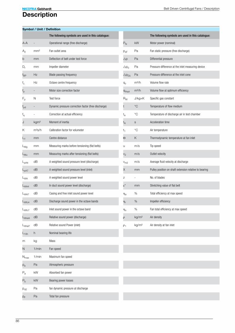
86
A-A -
A2 mm²
b mm
Dr mm
fBP Hz
fc Hz
fp -
Fp N
fpd -
fh -
J kgm²
K m²s/h
LT mm
LMg mm
LMu mm
LpA4 dB
LpA7 dB
LWA dB
LWA4 dB
LWA7 dB
LWfc4 dB
LWfc7 dB
LWrel4 dB
LWrel7 dB
L10h h
m kg
N 1/min
Nmax 1/min
pa Pa
Pa kW
Pb kW
pd2 Pa
pF Pa
PN kW
psF Pa
gp Pa
gp0 Pa
gpDü Pa
qv m³/h
qVopt m³/h
RW J/kg×K
t °C
ta °C
tA s
t1 °C
Θ K
u m/s
v2 m/s
vm2 m/s
X mm
z -
e* mm
ha %
hr %
hs %
r kg/m²
r1 kg/m²
DescriptionBelt Driven Centrifugal Fans / Description
Symbol / Unit / Definition
Operational range (free discharge)
Fan outlet area
Deflection of belt under test force
Impeller diameter
Blade passing frequency
Octave centre frequency
Motor size correction factor
Test force
Dynamic pressure correction factor (free discharge)
Correction at actual efficiency
Moment of inertia
Calibration factor for volumeter
Centre distance
Measuring marks before tensioning (flat belts)
Measuring marks after tensioning (flat belts)
A weighted sound pressure level (discharge)
A weighted sound pressure level (inlet)
A weighted sound power level
In duct sound power level (discharge)
Casing and free inlet sound power level
Discharge sound power in the octave bands
Inlet sound power in the octave band
Relative sound power (discharge)
Relative sound Power (inlet)
Nominal bearing life
Mass
Fan speed
Maximum fan speed
Atmospheric pressure
Absorbed fan power
Bearing power losses
fan dynamic pressure at discharge
Total fan pressure
The following symbols are used in this catalogue: The following symbols are used in this catalogue:
Motor power (nominal)
Fan static pressure (free discharge)
Differential pressure
Pressure difference at the inlet measuring device
Pressure difference at the inlet cone
Volume flow rate
Volume flow at optimum efficiency
Specific gas constant
Temperature of flow medium
Temperature of discharge air in test chamber
Acceleration time
Air temperature
Thermodynamic temperature at fan inlet
Tip speed
Outlet velocity
Average fluid velocity at discharge
Pulley position on shaft extension relative to bearing
No. of blades
Stretching value of flat belt
Total efficiency at max speed
Impeller efficiency
Fan total efficiency at max speed
Air density
Air density at fan inlet
87
DIN EN ISO 9001Nicotra Gebhardt quality is the result of a continuous company policy intended to guarantee that our product properties and features are clearly superior to comparable products. This already established company maxim led in April 1985 to the auditing and certification of the existing quality management system. In the following years it was updated to match the changing international and European standards. Modern production processes, monitored by our quality management system, guarantee a high repeat accuracy in production. This ongoing high standard of quality permits the establishing of the performance data in classes of accuracy in accordance with DIN 24166. The narrow tolerances ensure a high level of data reliability for our products.
The fans contained in this catalogue are not machines in the sense of the EC Machine Directive. They are delivered with a manufacturer "Declaration of incorporation". The assessment of the dangers associated with the fan and necessary safety measures are based on the VDMA Unit sheet 24167: Fans; Safety requirements. The operating instructions give which safety measures are still necessary on assembly to ensure that the fans comply with the Machine Directive 2006/42/EC.
We reserve the right to change any measurements and technical data in this catalogue in accordance with further development of our products. All information valid at the time of printing.
NotesBelt Driven Centrifugal Fans / Description / Notes
Quality management system
Machine Safety
Catalogue data
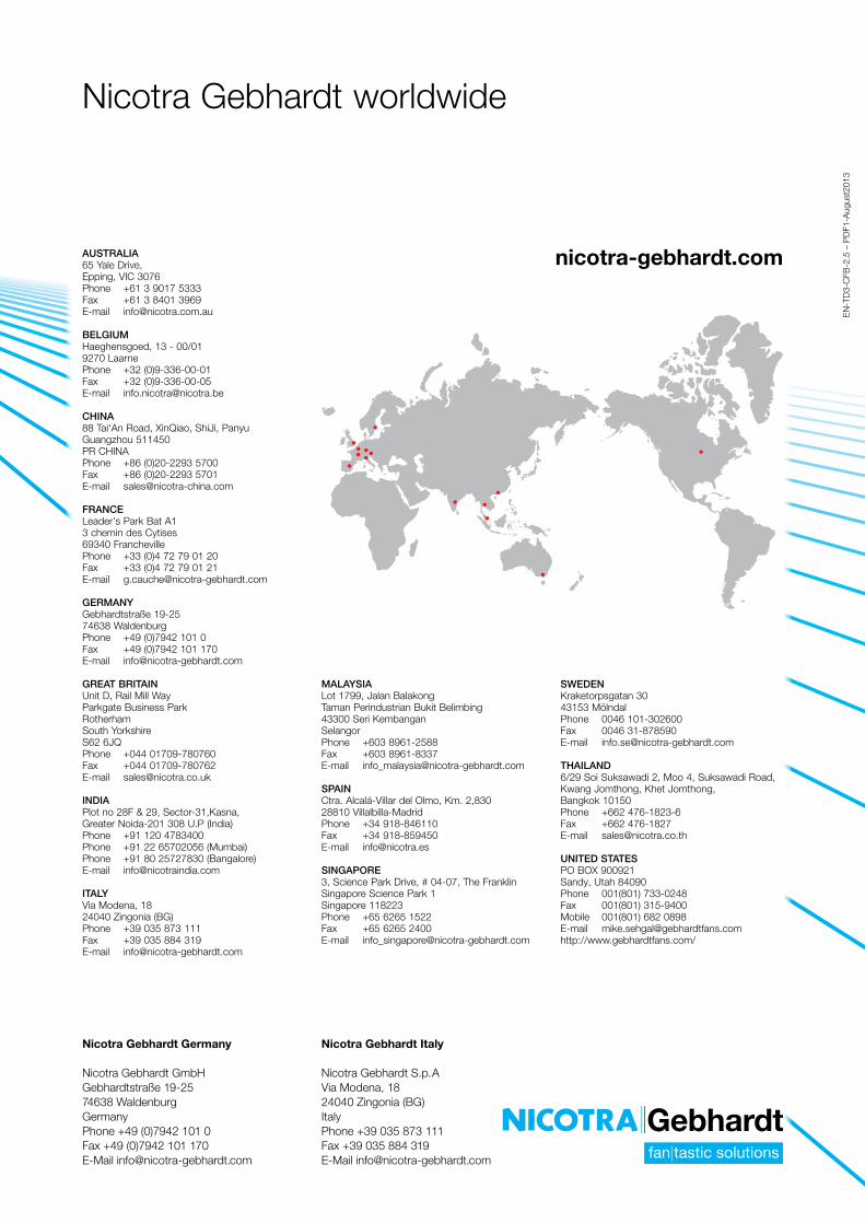
88
nicotra-gebhardt.com
EN
-TD
3-C
FB-2
.5 –
PD
F1-A
ugus
t201
3
nicotra-gebhardt.comAUSTRALIA65 Yale Drive,Epping, VIC 3076Phone +61 3 9017 5333Fax +61 3 8401 3969E-mail [email protected]
BELGIUM Haeghensgoed, 13 - 00/019270 LaarnePhone +32 (0)9-336-00-01Fax +32 (0)9-336-00-05E-mail [email protected]
CHINA88 Tai‘An Road, XinQiao, ShiJi, Panyu Guangzhou 511450PR CHINA Phone +86 (0)20-2293 5700Fax +86 (0)20-2293 5701 E-mail [email protected]
FRANCE Leader's Park Bat A13 chemin des Cytises69340 FranchevillePhone +33 (0)4 72 79 01 20Fax +33 (0)4 72 79 01 21E-mail [email protected]
GERMANY Gebhardtstraße 19-2574638 WaldenburgPhone +49 (0)7942 101 0 Fax +49 (0)7942 101 170 E-mail [email protected]
GREAT BRITAIN Unit D, Rail Mill WayParkgate Business ParkRotherhamSouth YorkshireS62 6JQPhone +044 01709-780760Fax +044 01709-780762 E-mail [email protected]
INDIAPlot no 28F & 29, Sector-31,Kasna, Greater Noida-201 308 U.P (India)Phone +91 120 4783400Phone +91 22 65702056 (Mumbai)Phone +91 80 25727830 (Bangalore)E-mail [email protected]
ITALY Via Modena, 1824040 Zingonia (BG)Phone +39 035 873 111Fax +39 035 884 319E-mail [email protected]
MALAYSIA Lot 1799, Jalan BalakongTaman Perindustrian Bukit Belimbing 43300 Seri Kembangan SelangorPhone +603 8961-2588 Fax +603 8961-8337 E-mail [email protected]
SPAIN Ctra. Alcalá-Villar del Olmo, Km. 2,83028810 Villalbilla-Madrid Phone +34 918-846110Fax +34 918-859450E-mail [email protected]
SINGAPORE 3, Science Park Drive, # 04-07, The FranklinSingapore Science Park 1Singapore 118223Phone +65 6265 1522Fax +65 6265 2400E-mail [email protected]
SWEDEN Kraketorpsgatan 3043153 Mölndal Phone 0046 101-302600Fax 0046 31-878590E-mail [email protected]
THAILAND 6/29 Soi Suksawadi 2, Moo 4, Suksawadi Road, Kwang Jomthong, Khet Jomthong, Bangkok 10150Phone +662 476-1823-6Fax +662 476-1827E-mail [email protected]
UNITED STATESPO BOX 900921Sandy, Utah 84090Phone 001(801) 733-0248 Fax 001(801) 315-9400 Mobile 001(801) 682 0898E-mail [email protected]://www.gebhardtfans.com/
Nicotra Gebhardt worldwide
Nicotra Gebhardt Germany
Nicotra Gebhardt GmbHGebhardtstraße 19-2574638 WaldenburgGermanyPhone +49 (0)7942 101 0 Fax +49 (0)7942 101 170 E-Mail [email protected]
Nicotra Gebhardt Italy
Nicotra Gebhardt S.p.AVia Modena, 1824040 Zingonia (BG)ItalyPhone +39 035 873 111Fax +39 035 884 319E-Mail [email protected]