centrifugal pumps - springer978-3-642-40114-5/1.pdf · centrifugal pumps 3rd edition ... to select,...
TRANSCRIPT

Centrifugal Pumps

Johann Friedrich Gülich
Centrifugal Pumps3rd Edition
2123
ISBN 978-3-642-40113-8 ISBN 978-3-642-40114-5 (eBook)DOI 10.1007/978-3-642-40114-5Springer Heidelberg Dordrecht London New York
Library of Congress Control Number: 2013951850
© Springer-Verlag Berlin Heidelberg 2008, 2010, 2014This work is subject to copyright. All rights are reserved, whether the whole or part of the material is con-cerned, specifically the rights of translation, reprinting, reuse of illustrations, recitation, broadcasting, reproduction on microfilm or in any other way, and storage in data banks. Duplication of this publication or parts thereof is permitted only under the provisions of the German Copyright Law of September 9, 1965, in its current version, and permission for use must always be obtained from Springer. Violations are liable to prosecution under the German Copyright Law.The use of general descriptive names, registered names, trademarks, etc. in this publication does not im-ply, even in the absence of a specific statement, that such names are exempt from the relevant protective laws and regulations and therefore free for general use.
Printed on acid-free paper
Springer is part of Springer Science+Business Media (www.springer.com)
Dr. Ing. Johann Friedrich GülichVilleneuve, [email protected]
v
Preface
Life is linked to liquid transport, and so are vital segments of economy. Pumping devices—be it the human heart, a boiler feeder or the cooling-water pump of a motorcar—are always part of a more or less complex system where pump failure can lead to severe consequences. To select, operate or design a pump, some unders-tanding of the system is helpful, if not essential. Depending on the application, a centrifugal pump can be a simple device which could be built in a garage with a minimum of know-how—or a high-tech machine requiring advanced skills, sophis-ticated engineering and extensive testing. When attempting to describe the state-of-the-art in hydraulic engineering of centrifugal pumps, the focus is necessarily on the high-tech side rather than on less-demanding services even though these make up the majority of pump applications.
Centrifugal pump technology involves a broad spectrum of flow phenomena which have a profound impact on design and operation through the achieved effi-ciency, the stability of the head-capacity characteristic, vibration, noise, component failure due to fatigue, as well as material damage caused by cavitation, hydro-ab-rasive wear or erosion corrosion. Operation and life cycle costs of pumping equip-ment depend to a large extent on how well these phenomena and the interaction of the pump with the system are understood.
This book endeavors to describe pump hydraulic phenomena in their broadest sense in a format highly relevant for the pump engineer involved in pump design and selection, operation and troubleshooting. Emphasis is on physical mechanisms, practical application and engineering correlations for real flow phenomena, rather than on mathematical treatment and theories of inviscid flow.
The present 3rd English edition has been enhanced by:
1. As a novelty, Sect. 7.14 provides a fully analytical method for the design of radial impellers. It can be applied to any type of pump, any specific speed and any user-imposed boundary conditions. The method provides a unique geome-try for any given set of specified design conditions: every designer gets (within minutes) exactly the same geometry. Apart from drastically speeding up impeller development, the goal is to eliminate the arbitrary elements from the design pro-cess and to reduce the uncertainty of performance prediction.

vi Preface
2. Hydraulic instabilities in pumps with double-entry impellers and double-volutes are discussed in Sect. 5.8.
3. The axial force on double-entry impellers is governed by the skewed velocity distribution at the impeller outlet; Sect. 9.2.4 provides data for estimating such effects. Further, equations are given for estimating the effect of complex impeller side room geometries on performance and axial forces.
4. Sect. 7.4 has been supplemented with additional information on sewage pump design. Sect. 9.3.9 provides detailed information on the hydraulic imbalance of single-channel impellers and correlations for predicting these forces.
5. With the object of helping with vibration diagnostics, Chap. 10 has been signi-ficantly enhanced by a more detailed discussion of various unsteady flow phe-nomena and their impact on hydraulic excitation forces. A physical model is presented for the axial thrust reversal in single-stage pumps with double-entry impellers. Some more interesting case histories concerning vibration problems have been added. The interaction of acoustic waves with the flow in the impeller channels and associated excitation forces is also discussed in chap. 10.
6. Sect. 6.8 has been expanded with a more detailed discussion of cavitation damage in diffusers and volutes.
7. Chapters 4 and 13 provide new insights and data on hydraulic losses including those in highly viscous fluids.
8. Chapter 16 on testing centrifugal pumps has been added.9. Some printing errors were corrected and some additions were made in most of
the chapters.
June 2014 J.F. GülichVilleneuve (Switzerland)

vii
Acknowledgements
The 1st English edition owed its existence to the initiative and sponsoring of the management of Sulzer Pumps. For this I am most grateful to Dr. A. Schachenmann who initiated the project, R. Paley and Dr. R. Gerdes.
The book benefited from the help which I got from many colleagues at Sulzer Pumps in the US and the UK to whom my sincere thanks are extended. Most im-portant were the reviews of the English text. M. Cropper was instrumental in this activity. S. Bradshaw, R. Davey, Dr. J. Daly, D. Eddy, M. Hall, Dr. A. Kumar, P. Sandford, D. Townson, and C. Whilde reviewed individual chapters.
J.H. Timcke meticulously checked most of the 1st English edition for consistency with the 2nd German edition and made many suggestions for making the text and figures easier to understand. Mrs. H. Kirchmeier helped with the figures and com-puter problems. Last but not least, my wife Rosemarie Gülich was a tremendous help in checking and improving the final text.
I am grateful to various individuals who provided me with literature and granted permission for using figures: Prof. Dr.-Ing. F. Avellan, Dr. M. Farhat, Dr. O. Braun and Dr. S. Berten from the Ecole Polytechnique Lausanne; Prof. Dr.-Ing. D.H. Hell-mann, Prof. Dr. Ing. M. Böhle and Dr. Ing. H. Roclawski from the Technical Uni-versity Kaiserslautern; Prof. Dr.-Ing. G. Kosyna, Prof. Dr.-Ing. habil. U. Stark, Mrs. Dr.-Ing. I. Goltz, Mrs. P. Perez, Dr. Ing. H. Saathoff from the Technical University Braunschweig; C.H. van den Berg, MTI Holland; Prof. Dr.-Ing. H. Wurm, A. Töws Wilo Dortmund; Dr. P. Dupont, Sulzer; U. Diekmann, Wilo-Emu, A. Nicklas, Ster-ling Fluid Systems, T. Folsche CP Pumpen AG, H. Bugdayci (IHC Merwede). I’m especially grateful R. Palgrave for sharing with me a number of instructive photo-graphs of pump components which have been subject to abrasive wear.
The 1st and 2nd editions benefited from the reviews of individual chapters pro-vided by: Dr.-Ing. G. Scheuerer, ANSYS München and Dr. P. Heimgartner, W. Bol-liger, W. Schöffler, Dr.-Ing. W. Wesche, Dr. P. Dupont, Dr. S. Berten, G. Caviola, E. Leibundgut, T. Felix, A. Frei, E. Kläui, W. Handloser (all from Sulzer) and J.H. Timcke.

viii Acknowledgements
The following organizations or individuals kindly granted permission for using figures:
• SulzerPumpsLtd,Winterthur• T.McCloskey,ElectricPowerResearchInstitute,PaloAlto,CA,USA• VDMA,Frankfurt• VDI-Verlag,Düsseldorf• Mr.J.Falcimaigne,InstitutFrançaisduPétrole,Paris• ASMENewYork
The appropriate references are given in the figure captions.

ix
Symbols, abbreviations, definitions
Hints for the reader: The text is written according to US-English spelling rules.As is customary in English publications, the decimal point is used.
Nomenclature: Unfortunately there is no commonly accepted nomenclature and use of technical terms. As far as possible I have consulted various standards as to the most accepted terms. The reader is referred to the extensive list of symbols given below. For easy reference, this list defines the chapters, tables or equations where the respective symbols are introduced. A number of subscripts from the German original were left unchanged since replacing them by meaningful English abbre-viations involved too much of a risk of overlooking some items which are used throughout the text and the equations.
Conventions: Equations, tables and figures are numbered by chapter. The geome-trical dimensions of impellers, diffusers and volutes are defined in Table 0.2.
To improve the readability, simplified expressions have sometimes been used (for example “volute” instead of “volute casing”). In order to avoid monotonous repetition of technical terms, synonyms are (sparingly) employed.
Formulae frequently used in practice were gathered in tables which present the sequence of calculation steps required to solve a specific problem. These tables help to find information quickly without looking through a lot of text; they also facilitate programming. The equations presented in the tables are labeled by “T”. For exam-ple Eq. (T3.5.8) refers to equation 8 in Table 3.5. Most of the tables are labeled as “Table 6.1”, for example. Some “data tables” are referred to as “Table D6.1” for instance; this subterfuge was made necessary by the layout of the German editions which contained “tables” and “plates”.
Mathematical expressions: Empirical data in the literature are frequently presen-ted in graphical form. In most cases such data are given in this book in the form of approximate equations in order to ease programming and to save space.
x Symbols, abbreviations, definitions
For reasons of simplicity the upper limit of a sum is not specified when there can be no doubt about the variable. For example, ∑st RRP stands for i
zst 1
1 PRR,i and repre-sents the sum of the disk friction losses in all stages of a multistage pump.
An equation of the form y = a × exp(b) stands for y = a × eb, where “e” is the base of the natural logarithm.
The symbol ~ is used for “proportional to”; for example, PRR ~ d25 stands for “the
disk friction loss is proportional to the 5th power of the impeller diameter”.Frequent reference is made to the specific speed nq which is always calculated
with n in rpm, Q in m3/s and H in m. For conversion to other units refer to Tab-le D2.1 or Table 3.4. For simplicity, the specific speed nq is treated as a dimension-less variable even though this is not true.
Many diagrams were calculated with MS-Excel which has limited capabilities for graphic layout. For example: 1E + 03 stands for 103; curve legends cannot show symbols or subscripts. The sketches should not be understood as technical drawings. Equations in the text are written for clarity with multiplier sign, i.e. a × b (instead of a b). This is not done in the numbered equations.
Literature: There is a general bibliography quoted as [B.1], [B.2], etc. while stan-dards are quoted as [N.1], [N.2], etc. The bulk of the literature is linked to the indi-vidual chapters. This eases the search for literature on a specific topic. The roughly 600 quotations provided represent only 1 % (order of magnitude) if not less of the relevant literature. This statement applies to all topics treated in this book. The literature quoted was selected with the objectives: (1) to provide the sources of spe-cific data or information; (2) to back up a statement; (3) to refer the reader to more details on the particular investigation or topic; (4) to provide reference to literature in neighboring fields. In spite of these criteria, the selection of the literature quoted is to some extent coincidental.
In order to improve the readability, facts which represent the state of the art are not backed up systematically by quoting literature where they may have been repor-ted. In many cases it would be difficult to ascertain where such facts were published for the first time.
Patents: Possible patents on any devices or design features are not necessarily men-tioned. Omission of such mention should not be construed so as to imply that such devices or features are free for use to everybody.
Disclaimer of warranty and exclusion of liabilities: In spite of careful checking text, equations and figures, neither the Springer book company nor the author:
• makeanywarrantyorrepresentationwhatsoever,expressorimplied,(A)withrespect of the use of any information, apparatus, method, process or similar item disclosed in this book including merchantability and fitness for practical purpo-se, or (B) that such use does not infringe or interfere with privately owned rights, including intellectual property, or (C) that this book is suitable to any particular user’s circumstances; or

xiSymbols, abbreviations, definitions
• assumeresponsibility foranydamageorother liabilitywhatsoever (includingconsequential damage) resulting from the use of any information, apparatus, method, process or similar item disclosed in this book.
In this context it should well be noted that much of the published information on pump hydraulic design is empirical in nature. The information has been gathered from tests on specific pumps. Applying such information to new designs harbors uncertainties which are difficult to asses and to quantify.
Finally it should be noted that the technological focus in the various sectors of the pump industry is quite different. Low-head pumps produced in vast quanti-ties are designed and manufactured to other criteria than engineered high-energy pumps. This implies that the recommendations and design rules given in this book cannot be applied indistinctly to all types of pumps. Notably, issues of standardiza-tion and manufacturing are not addressed in this text.
Symbols, abbreviations, definitions
Unless otherwise noted all equations are written in consistent units (SI-System). Most symbols are defined in the following. As appropriate, the equation or chapter is quoted where the symbol has been defined or introduced. Vectors in the text and in equations are printed as bold characters. Symbols with local significance only are defined in the text.
The following tables may help the understanding of the physical meaning of various parameters of prime importance:
• Table0.1and0.2:Geometricdimensionsoftheflowchannels,flowanglesandvelocities
• Table2.2:Headandnetpositivesuctionhead(NPSH)• Tables3.1and3.2:Velocitytriangles• Table3.4:Modellawsanddimensionlessparameters
Chapter or Equation
A area, cross sectionA elongation at rupture Chap. 14A amplitude Chap. 10A1q impeller inlet throat area (trapezoidal: A1q = a1×b1)A2q area between vanes at impeller outlet (A2q = a2×b2)A3q diffuser/volute inlet throat area (A3q = a3×b3)a distance between vanes (subscript 1to 6) Table 0.2a sound velocity in a pipe Eq. (10.17)ao sound velocity in the fluid Eq. (10.17)aL sound velocity in the casing material Eq. (T6.1.7)BEP best efficiency pointb accelerationb width of channel in the meridional section

xii Symbols, abbreviations, definitions
b2 impeller outlet width; if double-entry, per impeller sideb2tot (b2ges) impeller outlet width including shrouds Eq. (9.6)bks solid-borne noise acceleration Eq. (10.6)CNL cavitation sound pressure Table 6.1CV solid-borne noise as RMS of accelerationCV* dimensionless solid-borne noise acceleration CV* = CV×d1/u1
2
c absolute velocity Chap. 1.1c rotor damping coefficient Eq. (10.7)cA axial thrust reduction coefficient Eq. (9.4), Table 9.1cd flow velocity in discharge nozzlecFe concentration of iron ions Eq. (14.7), Table 14.7c3q average velocity in diffuser throat c3q = QLe/(zLe×A3q)cc cross coupled damping Eq. (10.7)ceq roughness equivalence factor Eq. (1.36b)cf friction coefficient of a flat plate Eq. (1.33)cp pressure recovery coefficient Eqs. (1.11), (1.40),
(T9.1.5)cp specific heat at constant pressure Chap. 13.2cph phase velocity Chap. 10.7.1cs flow velocity in suction nozzlecs concentration of solids Table 14.16cs,eq equivalent concentration of solids Table 14.16cT velocity at inlet to suction bell Eq. (11.15)cv solids volume concentration Table 13.5D damping coefficient Chap. 10.6.5D, d diameterDfz diffusion factor Table 7.5DE drive endDR liquid/gasdensityratioDR≡ρ*=ρ′/ρ″ Chap. 13.2DT inlet diameter of suction bell Fig. (11.20)d3q equivalent diameter of volute throat Eq. (T7.7.7)db arithmetic average of diameters at impeller or diffuser
e.g. d1b = 0.5 (d1 + d1i); defined such that: A1=π×d1b×b1
Table 0.2
dd inner diameter of discharge nozzledk Ball passage (sewage or dredge pumps) Chap. 7.4dm geometric average of diameters at impeller or diffuser,
e.g. d = 0.5(d +d )1m 1a2
1i2
Table 0.2
dn hub diameterdD diameter at shaft seal Table 9.1ds inner diameter of suction nozzleds diameter of solid particles Table 14.16E Young’s modulus of elasticityER maximum erosion rate (at location of highest metal loss) Table 6.1ER,a metal loss rate in mm/a Tables 14.7 and 14.16e vane thickness Table 0.2F forceFax axial force (“axial thrust”)FDsp radial thrust correction factor for double volutes,
Fig. 9.18 Table 9.4FR radial force (“radial thrust”) Eq. (9.6), Table 9.4

xiiiSymbols, abbreviations, definitions
Fr Froude number Chap. 11.7.3Fr, Ft radial- and tangential forces on rotor Eq. (10.8)Fcor corrosion factor Table 6.1FMat material factor for cavitation: Table 6.1, for abrasion:
Table 14.16f frequencyfEB natural frequency at operational speed Chap. 10.6.5fe1 natural frequency Chap. 10.6.2fkr critical speed (as frequency) Chap. 10.6.5fL influence of leakage flow on disk friction Eq. (T3.6.7), Table 3.6fn frequency of rotation fn = n/60fq impeller eyes per impeller: single-entry fq = 1; double-
entry fq = 2fH correction factor for head (roughness, viscosity) Eq. (3.32)fQ correction factor for flow rate (viscosity) Eq. (3.32)fR roughness influence on disk friction Eq. (T3.6.6)fRS frequency of rotating stallfη correction factor for efficiency (roughness, viscosity) Eq. (3.31)g acceleration due to gravity (g = 9.81 m/s2, rounded) Appendix 17.4H head per stage Tables 2.2, 3.3HMat hardness of material Table 14.16Hs hardness of solid particle Table 14.16Htot total head of a multistage pump Table 2.2Hp static pressure rise in impeller Eq. (T3.3.8)htot total enthalpy Eq. (1.4)h casing wall thickness (at location of accelerometer) Table 6.1hD casing cover wall thickness Table 6.1Iac acoustic intensity Table 6.1IRef reference value for intensity Table 6.1i incidence (i = blade angle minus flow angle) Table 3.1Jsp integral over diffuser or volute throat area Eq. (3.15); (4.13)k rotation of fluid in impeller sidewall gap k = β/ω Eq. (9.1), Table 9.1kE, kz rotation of fluid at inlet to impeller sidewall gap Fig. 9.1k stiffness Eq. (10.7)kc cross coupled stiffness Eq. (10.7)kn blockage caused by hub: kn=1−dn
2/d12
kR radial thrust coefficient (steady component) Eq. (9.6)kR,D radial thrust coefficient referred to d2 (steady) Table 9.4kR,dyn dynamic (unsteady) radial thrust coefficient Table 9.4kR,tot total radial thrust coefficient (steady and unsteady) Table 9.4kR,o radial thrust coefficient (steady) for operation at Q = 0 Table 9.4kRu radial thrust coefficient (steady) Eq. (9.7)kRR disk friction coefficient Table 3.6L lengthLPA A-type sound pressure level Table 10.4LDam damage lengthLcav cavity lengthM torquem difference of impeller and diffuser periodicity Chap. 10.7.1m mass coefficient Eq. (10.7)

xiv Symbols, abbreviations, definitions
m mass flow ratemc cross coupled mass Eq. (10.7)NDE non drive endNPSH net positive suction headNPSHA net positive suction head available Table 2.2, Table 6.2NPSHi net positive suction head required for cavitation
inceptionNPSHR net positive suction head required according to a specific
cavitation criterionChap. 6.2.2, 6.2.5, 6.3
NPSHx net positive suction head required for operation with x-per cent head drop
Chap. 6.2.2
NL fluid-borne sound pressure as RMS value; NL* = 2NL/(ρ×u1
2)NLo background sound pressure Chap. 6.5n rotational speed (revolutions per minute)n(s) rotational speed (revolutions per second)nN nominal speednq specific speed [rpm, m3/s, m] Table D2.1, Chap. 3.4,
Table 3.4nss suction specific speed [rpm, m3/s, m] Chap. 6.2.4, Table 3.4P power; without subscript: power at coupling Pi inner power Table 3.5Pm mechanical power losses Table 3.5Pu useful power transferred to fluid Pu = ρ×g×Htot×Q Table 3.5PRR disk friction power Tables 3.6, 3.5PER specific erosion power PER = UR×ER Table 6.1Per disk friction power loss caused by balance device Table 3.6Ps3 power loss dissipated in inter-stage seal Tables 3.5, 3.7(1)PI pitting index Eq. (14.8)p static pressurep periodicity Chap. 10.7.1pamb ambient pressure at location of pump installation (usu-
ally atmospheric pressure)pe pressure above liquid level in suction reservoir Table 2.2pg gas pressure (partial pressure) Appendix 17.3pi implosion pressure Table 6.1pv vapor pressureQ flow rate, volumetric flowQLa flow rate through impeller: QLa = Q + Qsp + QE + Qh = Q/ηvQLe flow rate through diffuser: QLe = Q + Qs3 + QEQE flow rate through axial thrust balancing deviceQh flow rate through auxiliaries (mostly zero)QR rated flow or nominal flow rate Chap. 15Qsp leakage flow rate through seal at impeller inlet Tables 3.5, 3.7(1)Qs3 leakage flow rate through inter-stage seal Tables 3.5, 3.7(1)q* flow rate referred to flow rate at best efficiency point: q*≡Q/QoptR, r radius or gas constant Table 13.3RG degree of reaction Chap. 3.2Re Reynolds number, channel: Re = c×Dh/ν; plate or blade:
Re = w×L/ν

xvSymbols, abbreviations, definitions
Ro Rossby number Chap. 5.2Rm tensile strengthRMS root mean squarer3q equivalent radius of volute throat area Table 7.7S submergence Chap. 11.7.3S sound absorbing surface of inlet casing Table 6.1SG specificgravity;SG≡ρ/ρRefwithρRef = 1000 kg/m3
SStr Strouhal number Table 10.13s radial clearance Eq. (3.12), Fig. 3.12,
Fig. 3.15 Table 3.7(1) and (2)
sax axial distance between impeller shrouds and casing Fig. 9.1T temperaturet timet pitch: t = π×d/zLa (or zLe)tax axial casing part in impeller sidewall gap Fig. 9.1U wetted perimeter (of a pipe or channel)UR ultimate resilience: UR = Rm
2/(2×E) Table 6.1u circumferential velocity u = π×d×n/60V volumew relative velocityw1q average velocity in impeller throat area w1q = QLa/(zLa×A1q)x dimensionless radius x = r/r2 Table 9.1x gas (or vapor) mass content; mass concentration of solids Chap. 13xD mass concentration of dissolved gas Appendix 17.3xov overlap at impeller/diffuser side disks Fig. 9.1Y specific work Y = g×HYsch ≡ Yth specific work done by the impeller blades: Yth = g×Hth Table 3.3Yth∞ specific work done by the impeller blades with vane
congruent flowy+ dimensionless distance from the wall Table 8.1Z real gas factor Table 13.3Zh hydraulic losses (impeller: ZLa diffuser: ZLe)z height coordinatezLa number of impeller bladeszLe number of diffuser vanes (volute: number of cutwaters)zR number of return vaneszpp number of pumps operating in parallelzst number of stageszVLe number of vanes of pre-rotation control deviceα≡GVF gas content, gas volume fraction, void fraction Table 13.2α angle between direction of circumferential and absolute
velocityαk notch factor Eq. (T14.1.7)αT total absorption coefficient Table 6.1β angle between relative velocity vector and the negative
direction of circumferential velocityβ angular velocity of fluid between impeller and casing Chap. 9.1β mass transfer coefficient Chap. 14.3, Table 14.8γ impeller discharge coefficient (“slip factor”) Table 3.2δ* displacement thickness Eq. (1.18)
xvi Symbols, abbreviations, definitions
∆p*d pressure pulsations(dimensionless) Eq. (10.1)∆pa amplitude of pressure pulsations Chap. 10.2.6∆pp-p pressure pulsations measured peak-to-peak Chap. 10.2.6ε angle in polar coordinate systemε equivalent sand roughness Chap. 1.5.2εsp wrap angle of the inner volute (for double volutes) Table 0.2ζ loss coefficient (with subscript La, Le, Sp etc.) Table 3.8ζa lift coefficient Tables 7.1, 7.4ζw drag coefficient Table 7.4ηvol, ηv volumetric efficiency Eq. (T3.5.9)η overall efficiency (at coupling) Eq. (T3.5.3)ηi inner efficiency Eq. (T3.5.5)ηh hydraulic efficiency Eq. (T3.5.8) and
Table 3.8ηD diffuser efficiency Eq. (1.43)ηst stage efficiency Eq. (T3.5.7)θu similarity parameter for cavitation erosion Table 6.1ϑ diffuser opening angle Eq. (1.42)κ exponent of isentropic expansion/compression Table 13.3(2)λ angle between vanes and side disks (impeller or diffuser) Table 0.1λ power coefficient Table 3.4λ wave length Table 10.12λc, λw coefficient for NPSH calculation Eq. (6.10)λR friction coefficient for pipes and channels Eq. (1.36)µ dynamic viscosity: µ = ρ×νν kinematic viscosity: ν = µ/ρν hub ratio ν = dn/d1aν1, ν2 vibration orders, natural numbers (1, 2, 3, ….)ξ hydraulic vane loading according to [7.2] Table 7.1ρ densityρ" density of gas or saturated vaporρmat density of materialρp density of casing materialρs density of solids suspended in the fluids Chap. 13.4, 14.5σ cavitation coefficient (same subscripts as NPSH) Table 3.4σ mechanical stress Chap. 14.1τ blade blockage factor Table 0.1τ shear stressϕ flow coefficient Table 3.4ϕsp flow coefficient of impeller sidewall gap Table 9.1ψ head coefficient Table 3.4ψp pressure coefficient ofstatic pressure rise in impeller Table 3.3Ω orbit- (vibration-)circular frequency Chap. 10.6.2Ωlimit orbit frequency of stability limit Eq. (10.9)ω angular rotor velocityωE circular natural frequency Chap. 10ωs universal specific speed Table D2.1, Table 3.4
xviiSymbols, abbreviations, definitions
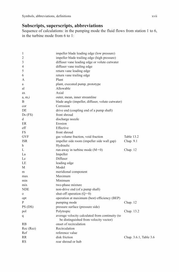
Subscripts, superscripts, abbreviationsSequence of calculations: in the pumping mode the fluid flows from station 1 to 6, in the turbine mode from 6 to 1:
1 impeller blade leading edge (low pressure)2 impeller blade trailing edge (high pressure)3 diffuser vane leading edge or volute cutwater4 diffuser vane trailing edge5 return vane leading edge6 return vane trailing edgeA Planta plant, executed pump, prototypeal Allowableax Axiala, m,i outer, mean, inner streamlineB blade angle (impeller, diffuser, volute cutwater)cor CorrosionDE drive end (coupling end of a pump shaft)Ds (FS) front shroudd discharge nozzleER Erosioneff EffectiveFS front shroudGVF gas volume fraction, void fraction Table 13.2ISR impeller side room (impeller side wall gap) Chap. 9.1h HydraulicL run-away in turbine mode (M = 0) Chap. 12La ImpellerLe DiffuserLE leading edgeM Modelm meridional componentmax Maximummin Minimummix two-phase mixtureNDE non-drive end (of a pump shaft)o shut-off operation (Q = 0)opt operation at maximum (best) efficiency (BEP)P pumping mode Chap. 12PS (DS) pressure surface (pressure side)pol Polytropic Chap. 13.2q average velocity calculated from continuity (to
be distinguished from velocity vector)RB onset of recirculationRec (Rez) RecirculationRef reference valueRR disk friction Chap. 3.6.1, Table 3.6RS rear shroud or hub

xviii Symbols, abbreviations, definitions
r Radials inlet or suction nozzles solid particle Chap. 13.4sch blade or vaneSF shockless flow
(zero incidence) Eq. (T3.1.10)
Sp Volutesp annular seal, leakage flowSPL single-phase liquidSS suction surface (suction side)st Stagestat StaticT turbine mode Chap. 12TE trailing edgeTP two-phaseTs (RS) rear shroud or hubth theoretical flow conditions (flow without
losses)tot total (total pressure = static pressure + stagnation
pressure)u circumferential componentv Lossv viscous fluid Chap. 13w water Chap. 13.1w resistance curve in turbine mode locked rotor
(n = 0)Chap. 12
zul (al) Allowable
The following are superscripts
′ with blade blockage Tables 0.1, 3.1* dimensionless quantity: all
dimensions are referred to d2 e.g. b2* = b2/d2, veloci-ties are referred to u2, e.g. w1* = w1/u2
′ liquid phase Chap. 6 & 13″ gaseous phase Chap. 6 & 13

xixSymbols, abbreviations, definitions

xx Symbols, abbreviations, definitions
ε
α
α
αα
β
β
α

xxiSymbols, abbreviations, definitions
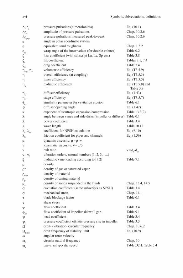
Impeller sidewall gaps and diffuser in-let geome-try for multistage pumps
Q S P
xo v
G ap A
d 2
sax
d w
Q S 3
d s3
d sp
d 3
Gap B
G ap F
G ap E
Im peller sidewall gap
Im peller sidew all g ap
Diffuser in-let geome-try with chamfer, for multi-stage pumps
[61]
Q SP
xov
Gap A
d2
sax
dw
Q S3
ds3
dsp
d3
Gap B
Gap F
Gap E
Impeller sidewall gap
Impeller sidewall gap
Chamfer
H2 d2
H3
H4
Triangular sectionDiffusing channel
Throat
Table 0.2 (2) Geometric dimensions

xxii Symbols, abbreviations, definitions

xxiiiSymbols, abbreviations, definitions
–
–

xxv
Contents
1 Fluid Dynamic Principles ....................................................................... 11.1 Flow in the Absolute and Relative Reference Frame ....................... 11.2 Conservation Equations ................................................................... 2
1.2.1 Conservation of Mass ........................................................... 21.2.2 Conservation of Energy ........................................................ 31.2.3 Conservation of Momentum ................................................ 5
1.3 Boundary Layers, Boundary Layer Control ..................................... 71.4 Flow on Curved Streamlines ............................................................ 11
1.4.1 Equilibrium of Forces .......................................................... 111.4.2 Forced and Free Vortices ...................................................... 151.4.3 Flow in Curved Channels ..................................................... 17
1.5 Pressure Losses ................................................................................ 181.5.1 Friction Losses (Skin Friction) ............................................. 191.5.2 Influence of Roughness on Friction Losses ......................... 211.5.3 Losses Due to Vortex Dissipation (Form Drag) ................... 25
1.6 Diffusers ........................................................................................... 271.7 Submerged Jets ................................................................................. 321.8 Equalization of Non-uniform Velocity Profiles ............................... 331.9 Flow Distribution in Parallel Channels, Piping Networks ...................... 36References ................................................................................................. 41
2 Pump Types and Performance Data ...................................................... 432.1 Basic Principles and Components .................................................... 432.2 Performance Data ............................................................................. 47
2.2.1 Specific Work, Head ............................................................. 472.2.2 Net Positive Suction Head, NPSH ....................................... 482.2.3 Power and Efficiency ........................................................... 502.2.4 Pump Characteristics ............................................................ 51
2.3 Pump Types and their Applications .................................................. 512.3.1 Overview .............................................................................. 512.3.2 Classification of Pumps and Applications ............................ 53

xxvi Contents
2.3.3 Pump Types .......................................................................... 552.3.4 Special Pump Types ............................................................. 72
References ................................................................................................. 77
3 Pump Hydraulics and Physical Concepts ............................................. 793.1 One-dimensional Calculation with Velocity Triangles ..................... 793.2 Energy Transfer in the Impeller, Specific Work and Head ............... 833.3 Flow Deflection Caused by the Blades. Slip Factor ........................ 853.4 Dimensionless Coefficients, Similarity Laws and Specific Speed ... 903.5 Power Balance and Efficiencies ....................................................... 933.6 Calculation of Secondary Losses ..................................................... 95
3.6.1 Disk Friction Losses ............................................................. 953.6.2 Leakage Losses Through Annular Seals .............................. 993.6.3 Power Loss Caused by the Inter-Stage Seal ......................... 1083.6.4 Leakage Loss of Radial or Diagonal Seals .......................... 1083.6.5 Leakage Losses in Open Impellers ...................................... 1093.6.6 Mechanical Losses ............................................................... 111
3.7 Basic Hydraulic Calculations of Collectors ..................................... 1113.8 Hydraulic Losses .............................................................................. 1173.9 Statistical Data of Pressure Coefficients, Efficiencies and Losses ... 1233.10 Influence of Roughness and Reynolds Number ............................... 132
3.10.1 Overview .............................................................................. 1323.10.2 Efficiency Scaling ................................................................ 1333.10.3 Calculation of the Efficiency from Loss Analysis ............... 135
3.11 Minimization of Losses .................................................................... 1403.12 Compendium of Equations for Hydraulic Calculations ................... 141References ................................................................................................. 156
4 Performance Characteristics ................................................................. 1594.1 Head-Capacity Characteristic and Power Consumption .................. 160
4.1.1 Theoretical Head Curve (Without Losses) ........................... 1604.1.2 Real Characteristics With Losses ......................................... 1624.1.3 Component Characteristics .................................................. 1654.1.4 Head and Power at Operation Against Closed
Discharge Valve .................................................................... 1734.1.5 Influence of Pump Size and Speed ....................................... 1764.1.6 Influence of Specific Speed on the Shape of the
Characteristics ...................................................................... 1774.2 Best Efficiency Point ........................................................................ 1774.3 Prediction of Pump Characteristics .................................................. 1824.4 Range Charts .................................................................................... 1834.5 Modification of the Pump Characteristics ........................................ 186
4.5.1 Impeller Trimming ............................................................... 1864.5.2 Under-Filing And Over-Filing of the Blades at the
Trailing Edge ........................................................................ 1944.5.3 Collector Modifications ....................................................... 195

xxviiContents
4.6 Analysis of Performance Deviations ................................................ 1954.7 Calculation of Modifications of the Pump Characteristics .............. 199References ................................................................................................. 203
5 Partload Operation, Impact of 3-D Flow Phenomena Performance ... 2055.1 Basic Considerations ........................................................................ 2055.2 The Flow Through the Impeller ....................................................... 209
5.2.1 Overview .............................................................................. 2095.2.2 Physical Mechanisms ........................................................... 2115.2.3 The Combined Effect of Different Mechanisms .................. 2175.2.4 Recirculation at the Impeller Inlet ........................................ 2195.2.5 Flow at the Impeller Outlet .................................................. 2255.2.6 Experimental Detection of the Onset of Recirculation ........ 227
5.3 The Flow in the Collector ................................................................. 2285.3.1 Flow Separation in the Diffuser ........................................... 2285.3.2 Pressure Recovery in the Diffuser ........................................ 2325.3.3 Influence of Approach Flow on Pressure Recovery
and Stall ................................................................................ 2335.3.4 Flow in the Volute Casing .................................................... 2345.3.5 Flow in Annular Casings and Vaneless Diffusers ................ 235
5.4 The Effects of Flow Recirculation ................................................... 2365.4.1 Effects of Flow Recirculation at the Impeller Inlet .............. 2365.4.2 Effect of Flow Recirculation at the Impeller Outlet ............. 2415.4.3 Effect of Outlet Recirculation on the Flow in the
Impeller Sidewall Gaps and on Axial Thrust ....................... 2485.4.4 Damaging Effects of Partload Recirculation ........................ 251
5.5 Influence of Flow Separation and Recirculation on the Q-H-Curve ........................................................................................ 2525.5.1 Types of Q-H-Curve Instability ............................................ 2525.5.2 Saddle-Type Instabilities ...................................................... 2535.5.3 Type F Instabilities ............................................................... 261
5.6 Means to Influence the Shape of The Q-H-Curve ............................ 2615.6.1 Introduction .......................................................................... 2615.6.2 Influencing the Onset of Recirculation at the
Impeller Inlet ........................................................................ 2625.6.3 Influencing the Onset of Recirculation at the
Impeller Outlet ..................................................................... 2655.6.4 Eliminating a Type F Instability ........................................... 2665.6.5 Influencing the Saddle-Type Instability of Radial
Impellers with nq < 50 ........................................................... 2675.6.6 Influencing the Saddle-Type Instability of Radial
Impellers with nq > 50 ........................................................... 2695.6.7 Influencing the Instability of Semi-Axial and Axial
Impellers ............................................................................... 2705.6.8 Reduction of Head and Power at Shut-Off ........................... 271
5.7 Flow Phenomena in Open Axial Impellers ...................................... 272

xxviii Contents
5.8 Flow Instabilities in Double-Entry Impellers and Double Volutes ... 280References ................................................................................................. 283
6 Suction Capability and Cavitation ........................................................ 2876.1 Cavitation Physics ............................................................................ 287
6.1.1 Growth and Implosion of Vapor Bubbles in a Flowing Liquid ..................................................................... 287
6.1.2 Bubble Dynamics ................................................................. 2896.2 Cavitation in Impeller or Diffuser .................................................... 292
6.2.1 Pressure Distribution and Cavity Length ............................. 2926.2.2 Required NPSH, Extent of Cavitation, Cavitation Criteria ... 2946.2.3 Scaling Laws for Cavitating Flows ...................................... 2966.2.4 The Suction Specific Speed .................................................. 2996.2.5 Experimental Determination of the Required NPSHR .......... 3026.2.6 Cavitation in Annular Seals .................................................. 311
6.3 Determination of the Required NPSH .............................................. 3126.3.1 Parameters Influencing NPSHR ............................................ 3126.3.2 Calculation of the NPSHR ..................................................... 3156.3.3 Estimation of the NPSH3 as Function of the Flow Rate ...... 319
6.4 Influence of the Fluid Properties ...................................................... 3236.4.1 Thermodynamic Effects ....................................................... 3236.4.2 Non-Condensable Gases ...................................................... 3266.4.3 Nuclei Content and Tensile Stresses in the Liquid ............... 327
6.5 Cavitation-Induced Noise and Vibrations ........................................ 3296.5.1 Excitation Mechanisms ........................................................ 3296.5.2 Cavitation Noise Measurements for Quantifying the
Hydrodynamic Cavitation Intensity ..................................... 3306.5.3 Frequency Characteristics of Cavitation Noise .................... 333
6.6 Cavitation Erosion ............................................................................ 3356.6.1 Testing Methods ................................................................... 3356.6.2 Cavitation Resistance ........................................................... 3386.6.3 Prediction of Cavitation Damage Based on Cavity Length ... 3406.6.4 Prediction of Cavitation Damage Based on
Cavitation Noise ................................................................... 3456.6.5 Solid-Borne Noise Measurements for Cavitation
Diagnosis .............................................................................. 3466.6.6 Paint Erosion Tests to Determine the Location of
Bubble Implosion ................................................................. 3486.6.7 Onset of Erosion and Behavior of Material Subject
to Different Hydrodynamic Cavitation Intensities ............... 3496.6.8 Summarizing Assessment ..................................................... 353
6.7 Selection of the Inlet Pressure in a Plant .......................................... 3556.8 Cavitation Damage: Analysis and Remedies ................................... 358
6.8.1 Record Damage and Operation Parameters ......................... 3586.8.2 Forms of Cavitation and Typical Cavitation
Damage Patterns ................................................................... 359

xxixContents
6.8.3 Reduction or Elimination of Cavitation Damage ................. 3696.9 Insufficient Suction Capacity: Analysis and Remedies .................... 371References ................................................................................................. 372
7 Design of the Hydraulic Components ................................................... 3757.1 Methods and Boundary Conditions .................................................. 375
7.1.1 Methods for the Development of Hydraulic Components ... 3757.1.2 The Hydraulic Specification ................................................. 3767.1.3 Calculation Models .............................................................. 378
7.2 Radial Impellers ............................................................................... 3807.2.1 Determination of Main Dimensions ..................................... 3807.2.2 Impeller Design .................................................................... 3897.2.3 Criteria for Shaping the Blades ............................................ 3967.2.4 Criteria for Suction Impeller Design .................................... 3977.2.5 Exploiting Three-Dimensional Effects in Design ................ 400
7.3 Radial impellers for Small Specific Speeds ..................................... 4017.3.1 Two-Dimensional Blades ..................................................... 4017.3.2 Pumping Disks with Channels of Circular Section .............. 4027.3.3 Impellers with Straight Radial Blades .................................. 4057.3.4 Double-Acting Impeller with Straight Radial Blades .......... 406
7.4 Radial Impellers for Non-Clogging Pumps ...................................... 4077.5 Semi-Axial Impellers ....................................................................... 4157.6 Axial Impellers and Diffusers .......................................................... 420
7.6.1 Features ................................................................................ 4207.6.2 Calculation and Selection of Main Dimensions ................... 4217.6.3 Basic Properties of Airfoils .................................................. 4267.6.4 Blade Design ........................................................................ 4327.6.5 Profile Selection ................................................................... 4407.6.6 Design of Axial Diffusers ..................................................... 442
7.7 Inducers ............................................................................................ 4447.7.1 Calculation of Inducer Parameters ....................................... 4457.7.2 Design and Shaping of an Inducer ....................................... 4507.7.3 Matching the Inducer to the Impeller ................................... 4517.7.4 Recommendations for Inducer Application ......................... 452
7.8 Volute Casings .................................................................................. 4547.8.1 Calculation and Selection of Main Dimensions ................... 4547.8.2 Design and Shaping of Volute Casings ................................ 4607.8.3 Influence of the Volute Shape on Hydraulic Performance ... 464
7.9 Radial Diffusers with or Without Return Channels ......................... 4677.9.1 Calculation and Selection of Main Dimensions ................... 4677.9.2 Design and Shaping of Radial Diffusers .............................. 473
7.10 Semi-Axial Diffusers ........................................................................ 4747.11 Volutes Combined with a Diffuser or Stay Vanes ............................ 4777.12 Annular Casings and Vaneless Diffusers .......................................... 4777.13 Inlet Casings for Between-Bearing Pumps ...................................... 478

xxx Contents
7.14 Analytical Method for Impeller Design ........................................... 4837.14.1 Motivation, Scope and Objectives ....................................... 4837.14.2 Meridional Section ............................................................... 4847.14.3 Blade Design ........................................................................ 4907.14.4 Procedure for Developing a Design Systematic ................... 4907.14.5 Some Results ........................................................................ 494
References ................................................................................................. 494
8 Numerical Flow Calculations ................................................................. 4998.1 Overview .......................................................................................... 4998.2 Quasi-3D-Procedures and 3D-Euler-Calculations ........................... 501
8.2.1 Quasi-3D- Procedures .......................................................... 5018.2.2 Three-Dimensional Euler-Procedures .................................. 502
8.3 Basics of Navier-Stokes Calculations .............................................. 5038.3.1 The Navier-Stokes Equations ............................................... 5038.3.2 Turbulence Models ............................................................... 5048.3.3 Treatment of Near-Wall Flows ............................................. 5088.3.4 Grid Generation .................................................................... 5118.3.5 Numerical Procedures and Control Parameters ................... 5148.3.6 Boundary Conditions ........................................................... 5168.3.7 Initial Conditions .................................................................. 5188.3.8 Possibilities of 3D-Navier-Stokes-Calculations ................... 519
8.4 Averaging and Post-Processing ........................................................ 5228.5 Impeller Calculations ....................................................................... 532
8.5.1 Global Performance at Best Efficiency Flow Rate .............. 5328.5.2 Velocity Profiles ................................................................... 5358.5.3 Influencing Parameters ......................................................... 5368.5.4 Sample Calculation .............................................................. 536
8.6 Calculation of Collectors and Stages ............................................... 5398.6.1 Separate Calculation of the Collector .................................. 5398.6.2 Steady Calculations of Stages or Complete Pumps ............. 5418.6.3 Unsteady Calculations .......................................................... 542
8.7 Two-Phase and Cavitating Flows ..................................................... 5438.8 Calculation Strategy, Uncertainties, Quality Issues ......................... 548
8.8.1 Uncertainties, Sources and Reduction of Errors .................. 5488.8.2 CFD Quality Assurance ........................................................ 5508.8.3 Comparison Between Calculation and Experiment ............. 561
8.9 Criteria for Assessment of Numerical Calculations ......................... 5638.9.1 General Remarks .................................................................. 5638.9.2 Consistence and Plausibility of the Calculation ................... 5648.9.3 Will the Specified Performance be Reached? ...................... 5648.9.4 Maximization of the Hydraulic Efficiency ........................... 565

xxxiContents
8.9.5 Stability of the Head-Capacity Curve .................................. 5678.9.6 Unsteady Forces ................................................................... 568
8.10 Fundamental Considerations on CFD-Calculations ....................... 568References ................................................................................................. 571
9 Hydraulic Forces ..................................................................................... 5759.1 Flow Phenomena in the Impeller Sidewall Gaps ............................. 5759.2 Axial Forces ..................................................................................... 592
9.2.1 General Procedure for Calculating Axial Forces ................. 5929.2.2 Single-Stage Pumps with Single-Entry Overhung
Impellers ............................................................................... 5959.2.3 Multistage Pumps ................................................................. 5969.2.4 Double-Entry Impellers ........................................................ 6049.2.5 Semi-Axial Impellers ........................................................... 6059.2.6 Axial Pumps ......................................................................... 6069.2.7 Expeller Vanes ...................................................................... 6069.2.8 Semi-Open and Open Impellers ........................................... 6099.2.9 Unsteady Axial Thrust .......................................................... 6099.2.10 Axial Thrust Calculation Overview ...................................... 610
9.3 Radial Forces .................................................................................... 6139.3.1 Definition and Scope ............................................................ 6139.3.2 Measurement of Radial Forces ............................................. 6159.3.3 Pumps with Single Volutes ................................................... 6169.3.4 Pumps with Double Volutes ................................................. 6229.3.5 Pumps with Annular Casings ............................................... 6249.3.6 Diffuser Pumps ..................................................................... 6249.3.7 Radial Forces Created by Non-Uniform Approach Flows ... 6259.3.8 Axial Pumps ......................................................................... 6269.3.9 Radial Forces in Pumps with Single-Channel Impellers ...... 6279.3.10 Radial Thrust Balancing ....................................................... 6409.3.11 Radial Thrust Prediction ....................................................... 641
References ................................................................................................. 646
10 Noise and Vibrations ............................................................................... 64910.1 Unsteady Flow at the Impeller Outlet .............................................. 65010.2 Pressure Pulsations ........................................................................... 653
10.2.1 Generation of Pressure Pulsations ........................................ 65410.2.2 Noise Generation in a Fluid ................................................. 65410.2.3 Influence Parameters of the Pump ....................................... 65510.2.4 Influence of the System ........................................................ 65810.2.5 Scaling Laws ........................................................................ 66010.2.6 Measurement and Evaluation of Pressure Pulsations ........... 66110.2.7 Pressure Pulsations of Pumps in Operation ......................... 66310.2.8 Damaging Effects of Pressure Pulsations ............................. 66310.2.9 Design Guidelines ................................................................ 666

xxxii Contents
10.3 Component Loading by Transient Flow Conditions ...................... 66810.4 Radiation of Noise .......................................................................... 669
10.4.1 Solid-Borne Noise ............................................................ 66910.4.2 Air-Borne Noise ................................................................ 671
10.5 Overview of Mechanical Vibrations of Centrifugal Pumps ........... 67410.6 Rotor Dynamics ............................................................................. 676
10.6.1 Overview .......................................................................... 67610.6.2 Forces in Annular Seals .................................................... 67710.6.3 Hydraulic Impeller Interaction ......................................... 68410.6.4 Bearing Reaction Forces ................................................... 68610.6.5 Eigen Values and Critical Speeds ..................................... 68710.6.6 Rotor Instabilities ............................................................. 690
10.7 Hydraulic Excitation of Vibrations ................................................ 69310.7.1 Interaction Between Flows Through
Rotor and Stator (RSI) ...................................................... 69310.7.2 Rotating Stall .................................................................... 70510.7.3 Various Hydraulic Excitation Mechanisms ...................... 708
10.8 Guidelines for the Design of Pumps with Low Sensitivity to Vibrations ................................................................................... 720
10.9 Allowable Vibrations ...................................................................... 72310.10 General Vibration Diagnostics ....................................................... 726
10.10.1 Overview .......................................................................... 72610.10.2 Vibration Measurements ................................................... 72710.10.3 Vibration Diagnostics ....................................................... 729
10.11 Bearing Housing Vibrations: Mechanism, Diagnostics, Remedies ........................................................................................ 73710.11.1 Hydraulic Excitation Mechanisms .................................... 73810.11.2 Mechanical Reaction to Hydraulic Excitation .................. 74210.11.3 Hydraulic Versus Mechanical Remedies .......................... 74510.11.4 Bearing Housing Vibration Diagnostics ........................... 746
10.12 Hydraulic and Acoustic Excitation of Pipe Vibrations ................... 75710.12.1 Excitation of Pipe Vibrations by Pumps ........................... 75810.12.2 Excitation of Pipe Vibrations by Components ................. 76010.12.3 Acoustic Resonances in Pipelines .................................... 76110.12.4 Hydraulic Excitation by Vortex Streets ............................ 76610.12.5 Coupling of Flow Phenomena with Acoustics ................. 76910.12.6 Pipe Vibration Mechanisms .............................................. 775
10.13 Torsional Vibrations ....................................................................... 779References ................................................................................................. 783
11 Operation of Centrifugal Pumps ........................................................... 78711.1 System Characteristics, Operation in Parallel or in Series ............. 78711.2 Pump Control ................................................................................. 79211.3 Static and Dynamic Stability .......................................................... 799
xxxiiiContents
11.4 Start-Up and Shut-Down ................................................................ 80111.5 Power Failure, Water Hammer ....................................................... 80611.6 Allowable Operation Range ........................................................... 80711.7 The Approach Flow to the Pump .................................................... 811
11.7.1 Suction Piping Layout ...................................................... 81111.7.2 Transient Suction Pressure Decay .................................... 81311.7.3 Pump Intakes and Suction from Tanks with Free
Liquid Level ..................................................................... 81911.7.4 Can Pumps ........................................................................ 834
11.8 Discharge Piping ............................................................................ 835References ................................................................................................. 839
12 Turbine Operation, General Characteristics ........................................ 84112.1 Reverse Running Centrifugal Pumps Used as Turbines ................ 841
12.1.1 Theoretical and Actual Characteristics ............................. 84112.1.2 Runaway and Resistance Characteristics ......................... 84712.1.3 Estimation of Turbine Characteristics from
Statistical Correlations ...................................................... 84912.1.4 Estimation of Turbine Characteristics from
Loss Models ...................................................................... 85312.1.5 Behavior of Turbines in Plants ......................................... 856
12.2 General Characteristics .................................................................. 861References ................................................................................................. 868
13 Influence of the Medium on Performance ............................................ 86913.1 Pumping Highly Viscous Fluids ..................................................... 869
13.1.1 Effect of Viscosity on Losses and Performance Characteristics .................................................................. 869
13.1.2 Estimation of Viscous Performance from the Characteristics Measured with Water ............................... 881
13.1.3 Influence of Viscosity on the Suction Capacity ................ 88713.1.4 Start-up of Pumps in Viscous Service .............................. 88813.1.5 Viscous Pumping Applications-
Recommendations and Comments ................................... 88913.2 Pumping of Gas-Liquid Mixtures .................................................. 890
13.2.1 Two-phase Flow Patterns in Straight Pipe Flow .............. 89013.2.2 Two-phase Flow in Pumps. Physical Mechanisms ........... 89413.2.3 Calculation of Two-phase Pump Performance ................. 90313.2.4 Radial Pumps Operating with Two-phase Flow ............... 91013.2.5 Helico-axial Multiphase Pumps ....................................... 91513.2.6 System Curves .................................................................. 91913.2.7 Slugs and Gas Pockets ...................................................... 92113.2.8 Free Gas, Dissolved Gas and NPSH ................................. 922

xxxiv Contents
13.3 Expansion of Two-phase Mixtures in Turbines .............................. 92413.3.1 Calculation of the Work Transfer ..................................... 92413.3.2 Prediction of Turbine Characteristics for
Two-phase Flow ............................................................... 92613.4 Hydraulic Transport of Solids ........................................................ 92913.5 Non-Newtonian Liquids ................................................................. 937References ................................................................................................. 940
14 Selection of Materials Exposed to High Flow Velocities ...................... 94314.1 Impeller or Diffuser Fatigue Fractures ........................................... 94414.2 Corrosion ........................................................................................ 956
14.2.1 Corrosion Fundamentals ................................................... 95614.2.2 Corrosion Mechanisms ..................................................... 95714.2.3 Corrosion in Fresh Water, Cooling Water, Sewage .......... 96314.2.4 Corrosion in Sea Water and Produced Water .................... 966
14.3 Erosion Corrosion in Demineralized Water ................................... 97114.4 Material Selection and Allowable Flow Velocities ........................ 980
14.4.1 Definition of Frequently Encountered Fluids ................... 98014.4.2 Metallic Pump Materials .................................................. 98214.4.3 Impellers, Diffusers and Casings ...................................... 98914.4.4 Wear Ring Materials ......................................................... 100014.4.5 Shaft Materials .................................................................. 100314.4.6 Materials for Feed Water and Condensate Pumps ............ 100414.4.7 Materials for FGD-Pumps ................................................ 100514.4.8 Composite Materials ......................................................... 1006
14.5 Hydro-abrasive Wear ...................................................................... 100814.5.1 Influence Parameters ........................................................ 100814.5.2 Quantitative Estimation of Hydro-Abrasive Wear ........... 101114.5.3 Material Behavior and Influence of Solids Properties ..... 101614.5.4 Material Selection ............................................................. 102114.5.5 Abrasive Wear in Slurry Pumps ........................................ 102214.5.6 Erosion Patterns and Flow Mechanisms ........................... 1024
References ................................................................................................. 1030
15 Pump Selection and Quality Considerations ........................................ 103515.1 The Pump Specification ................................................................. 103615.2 Determination of Pump Type and Size .......................................... 103815.3 Technical Quality Criteria .............................................................. 1044
15.3.1 Hydraulic Criteria ............................................................. 104415.3.2 Manufacturing Quality ..................................................... 1048
15.4 High-Energy Pumps ....................................................................... 1053References ................................................................................................. 1057

xxxvContents
16 Pump Testing ........................................................................................... 105916.1 Types of Tests and Measurements to be Taken .............................. 105916.2 Test Loop Configurations ............................................................... 1061
16.2.1 Types and Layout of Closed Test Loops ........................... 106316.2.2 Closed Test Loop with Pressurizer ................................... 106316.2.3 Semi-Open Test Loop ....................................................... 106816.2.4 Closed Test Loop with Flow Through Tank with
Free Water Level ............................................................... 106916.2.5 Open Test Loops ............................................................... 1070
16.3 Instrumentation .............................................................................. 107216.3.1 Pressure Measurement ...................................................... 107316.3.2 Flow Rate Measurement ................................................... 107316.3.3 Power, Torque and Efficiency Measurement .................... 1078
16.4 Test Preparation and Test Procedures ............................................. 107916.4.1 Test Preparation ................................................................ 107916.4.2 Procedure for Performance Test ....................................... 108016.4.3 Procedures for Cavitation Testing .................................... 1080
16.5 Test Evaluation and Accuracy ........................................................ 108116.6 Potential Testing Problems and Remedies ..................................... 1083References ................................................................................................. 1083
17 Appendices ............................................................................................... 108517.1 Units and Unit Conversion ............................................................. 108517.2 Properties of Saturated Water ......................................................... 108717.3 Solution of Gases in Water ............................................................. 109017.4 Physical Constants ......................................................................... 1093
17.4.1 Atmospheric Pressure ....................................................... 109317.4.2 Acceleration due to Gravity .............................................. 1093
17.5 Sound Velocity in Liquids .............................................................. 109317.6 Mechanical Vibrations—Basic Notions ......................................... 109417.7 Hydraulic Specification .................................................................. 1104References ................................................................................................. 1109
Bibliography ................................................................................................... 1111
Index ............................................................................................................... 1113

xxxvii
List of Tables
Table 0.1 Dimensions and flow parameters ............................................ xixTable 0.2 (1) Geometric dimensions ............................................................. xxTable 0.2 (2) Geometric dimensions ............................................................. xxiTable 1.1 Rankine vortex ........................................................................ 16Table 1.2 Submerged turbulent jets ......................................................... 33Table 1.3 Equalization of non-uniform velocity distributions
by flow resistances or acceleration ......................................... 34Table 1.4 Pressure loss coefficients ........................................................ 35Table 1.5 Calculation of pipe networks .................................................. 37Table 1.6 Friction losses of pipes and flat plates .................................... 38Table 1.7 (1) Diffuser design ........................................................................ 39Table 1.7 (2) Diffuser design ........................................................................ 40Table 2.1 Hydraulic pump components and arrangements ..................... 46Table 2.2 Total dynamic head and net positive suction head (NPSH) .... 49Table 2.3 Pump types .............................................................................. 54Table 2.4 Pump applications ................................................................... 56Table 3.1 Velocity triangle at impeller inlet ............................................ 142Table 3.2 Velocity triangle at impeller outlet .......................................... 143Table 3.3 Work transfer in impeller ........................................................ 144Table 3.4 Scaling laws and dimensionless coefficients .......................... 145Table 3.5 Power balance, efficiencies and losses .................................... 146Table 3.6 Friction losses of rotating disks or cylinders .......................... 147Table 3.7 (1) Leakage losses I: Annular seals ............................................... 148Table 3.7 (2) Leakage losses II: Radial or diagonal gaps, open impellers .... 149Table 3.7 (3) Screw-type pumping grooves in turbulent flow ...................... 150Table 3.8 (1) Hydraulic losses in impeller .................................................... 151Table 3.8 (2) Hydraulic losses in diffuser or volute ...................................... 152Table 3.9 Statistical efficiency data and efficiency scaling .................... 153Table 3.10 (1) Influence of roughness and Reynolds number on efficiency ....... 154Table 3.10 (2) Influence of roughness and Reynolds number on efficiency ....... 155Table 4.1 Diffuser/volute characteristic and best efficiency point .......... 178Table 4.2 Modification of pump characteristics...................................... 187

xxxviii List of Tables
Table 4.3 Analysis of performance deficits ............................................. 197Table 4.4 Modification of pump characteristics...................................... 200Table 5.1 (1) Interpretation and modification of pump characteristics ............ 263Table 5.1 (2) Interpretation and modification of pump characteristics ............ 264Table 6.1 (1) Assessment of the risk of cavitation damage ........................... 343Table 6.1 (2) Assessment of the risk of cavitation damage ........................... 344Table 6.2 Selection of available NPSHA to ensure safe operation .......... 356Table 6.3 Cavitation damage ................................................................... 360Table 6.4 Analysis of NPSH-Problems ................................................... 371Table 7.1 Impeller calculation ................................................................. 382Table 7.2 Sewage pump design data ....................................................... 410Table 7.3 Main dimensions of axial impellers ........................................ 423Table 7.4 Airfoils .................................................................................... 431Table 7.5 (1) Blade design of axial impellers ............................................... 433Table 7.5 (2) Blade design of axial impellers according to [32] ................... 434Table 7.5 (3) Blade design of axial impellers according to [32] ................... 435Table 7.5 (4) Blade design of axial impellers ............................................... 436Table 7.6 Inducer design ......................................................................... 446Table 7.7 Diffuser and volute design calculations .................................. 455Table 7.8 Normalized stream line equations ........................................... 485Table 7.9 Normalized stream line coordinates ........................................ 487Table 7.10 Blade design ............................................................................ 489Table 8.1 Law of the wall and velocity distributions .............................. 510Table 8.2 (1) CFD-post processing ............................................................... 530Table 8.2 (2) CFD-post processing ............................................................... 531Table 8.2 (3) CFD-post processing ............................................................... 532Table 8.3 Uncertainty of CFD-calculations of pumps
(1) Physical modeling ............................................................. 552Table 8.3 Uncertainty of CFD-calculations of pumps
(2) Physical modeling (data) ................................................... 553Table 8.3 Uncertainty of CFD-calculations of pumps
(3) Numerical modeling .......................................................... 553Table 8.4 (1) CFD-calculation of components and stages ............................ 557Table 8.4 (2) Stage calculations .................................................................... 558Table 9.1 (1) Rotation of the fluid in the impeller sidewall gaps.................. 597Table 9.1 (2) Rotation of the fluid in the impeller sidewall gaps.................. 598Table 9.2 Calculation of axial thrust on impeller .................................... 599Table 9.3 Semi-open impellers; expeller vanes ...................................... 608Table 9.4 Overview on axial thrust calculations ..................................... 611Table 9.5 Balance holes versus expeller vanes ....................................... 612Table 9.6 Hydraulic imbalance of single-blade impellers in volutes ...... 640Table 9.7 (1) Radial thrust calculation .......................................................... 643Table 10.1 Hydraulically induced damage to pump components ............. 665Table 10.2 Design guidelines for low pressure pulsations ........................ 667Table 10.3 Definition of noise levels ........................................................ 672

xxxixList of Tables
Table 10.4 Noise emission of pumps ...................................................... 673Table 10.5 Forced versus self-excited vibrations .................................... 693Table 10.6 Assessment of shaft vibrations based on the ratio of
peak-to-peak amplitudes to bearing clearance in new conditions ............................................................................... 724
Table 10.7 Assessment of shaft vibrations according to ISO 7919-3 and ISO 13709 (API 610) ......................................... 724
Table 10.8 Assessment of bearing housing vibrations according to ISO 13709 (API 610) and ISO 10816-7 ........... 725
Table 10.9 (1) Vibration Diagnostics ............................................................ 730Table 10.9 (2) Vibration Diagnostics ............................................................ 731Table 10.9 (3) Vibration Diagnostics ............................................................ 732Table 10.9 (4) Vibration Diagnostics ............................................................ 733Table 10.9 (5) Shaft versus bearing housing vibrations ................................ 735Table 10.9 (6) Damage patterns caused by shaft deflection ......................... 736Table 10.10 Impact of hydraulic design on bearing housing vibrations ... 747Table 10.11 Bearing housing vibration diagnostics A Fundamental frequencies and data treatment conditions ... 751 BPumpmaindata ................................................................. 752 C Vane number combinations; stage number: …………...... 753 D Measured vibrations .......................................................... 754 E Natural frequencies ............................................................ 755 F Diagnostics and remedies .................................................. 756 G Data relevant for interaction with rotor dynamics ............ 757 H Hydraulic design ............................................................... 757Table 10.12 Acoustical properties of system components ........................ 763Table 10.13 Excitation of vibrations by vortex streets.............................. 767Table 11.1 Calculation of suction pressure decay transients ................... 817Table 11.2 Critical submergence of suction bells ................................... 826Table 11.3 Empirical data for air-drawing surface vortices3 ................... 827Table 12.1 Turbine characteristics .......................................................... 850Table 12.1 (1) Turbine test data evaluation ................................................... 854Table 12.2 (2) Turbine test data evaluation ................................................... 855Table 12.3 Turbine performance prediction ............................................ 857Table 13.1 Estimation of characteristics for pumping viscous fluids ..... 884Table 13.2 (1) Estimation of pump characteristics when pumping
viscous fluids ......................................................................... 886Table 13.2 (2) Estimation of pump characteristics when pumping
viscous fluids ......................................................................... 887Table 13.3 (1) Gas-Liquid-Mixtures ............................................................. 908Table 13.3 (2) Polytropic compression of Gas-Liquid-Mixtures .................. 909Table 13.4 Expansion of gas-liquid mixtures ......................................... 927Table 13.5 Hydraulic transport of solids ................................................. 933Table 14.1 Impeller or diffuser vane loading .......................................... 945Table 14.2 Impeller shroud loading ........................................................ 946

xl List of Tables
Table 14.3 Thickness of blades, vanes and shrouds ................................ 955Table 14.4 Electrochemical potential in flowing sea water .................... 960Table 14.5 Water hardness ...................................................................... 964Table 14.6 (1) Materials for sea water at T < 30 °C ...................................... 968Table 14.6 (2) Materials for sea water at T < 30 °C ...................................... 969Table 14.7 Metal loss due to erosion corrosion in
demineralized water .............................................................. 976Table 14.8 Mass transfer correlations ..................................................... 977Table 14.9 Steel selection based on the pitting index PI ......................... 987Table 14.10 Determination of the allowable head per stage ..................... 991Table 14.11 Properties of cast irons and cast carbon steels ...................... 993Table 14.12 Properties of martensitic and austenitic cast steel ................. 994Table 14.13 Properties of duplex and super-austenitic cast steel .............. 995Table 14.14 Properties of super-duplex cast steel and wear ring
material .................................................................................. 996Table 14.15 Properties of wear resistant cast iron .................................... 997Table 14.16 Properties of copper and nickel alloys .................................. 998Table 14.17 Velocity limits for cast materials ........................................... 999Table 14.18 Wear ring materials ............................................................... 1001Table 14.19 Materials for shafts exposed to the fluid pumped ................. 1004Table 14.20 Properties of composite materials ......................................... 1007Table 14.21 Estimation of metal loss due to hydro-abrasive wear ........... 1017Table 15.1 Pump selection ...................................................................... 1040Table 15.2 Tolerances for impellers, diffusers and volutes ..................... 1049Table 15.3 Quality requirements for impellers and diffusers .................. 1052Table 15.4 Energy level of pumps and quality classes ........................... 1055Table 16.1 Measurements ....................................................................... 1061Table 16.2 (1) Closed test loop layout options ............................................. 1064Table 16.2 (2) Closed test loop layout options ............................................. 1065Table 16.3 Component list ...................................................................... 1067Table 16.4 Potential testing problems and remedies ............................... 1082Table 17.1 Properties of saturated water ................................................. 1088Table 17.2 Approximate formulae for the properties of
saturated water and vapor ...................................................... 1089Table 17.3 Solubility of gases in water ................................................... 1091Table 17.4 Free vibrations ....................................................................... 1095Table 17.5 Forced vibrations with viscous damping (periodic force)..... 1097Table 17.6 Forced vibrations with viscous damping .............................. 1099Table 17.7 Forced vibrations with viscous damping (imbalance
excitation) .............................................................................. 1101Table 17.8 Eigen frequencies of simple structures ................................. 1103

xli
List of Data Tables
TableD1.1 Roughnesslimitsε ....................................................................... 22Table D1.2 Roughness equivalence factors ceq ............................................... 24Table D1.3 Roughness classes ........................................................................ 24TableD1.4 Equivalentsandroughnessε ........................................................ 25Table D2.1 Definitions of specific speeds ...................................................... 52Table D6.1 Typical values of the suction specific speed ................................ 300Table D6.2 Typical NPSH-relationships at shockless entry............................ 306TableD6.3 Coefficientsλcandλw at shockless flow ...................................... 316Table D6.4 Material factors for cavitation damage prediction ....................... 351Table D6.5 Cavitation erosion in diffusers or volutes with double-
entry impellers .............................................................................. 369Table D7.1 Suction impeller design ................................................................ 399Table D7.2 Swirl distribution at impeller outlet ............................................. 419Table D7.3 Impeller blade numbers for nq > 140 ............................................ 426Table D7.4 Impeller-diffuser vane combinations ............................................ 469Table D7.5 Sample calculations ...................................................................... 493Table D9.1 Radial force measurements with single-blade impellers .............. 630Table D10.1 Addition of different noise sources .............................................. 672Table D10.2 Excitation forces in 90°-bend at R/D = 1.0 .................................. 769Table D10.3 Allowable pipe vibration velocities according to ISO
10816-1. ........................................................................................ 779Table D13.1 Pumping limits of radial impellers at suction pressure
of about 1 bara .............................................................................. 915