centrifugal utility fans - refri-perú
TRANSCRIPT

November2017
Centrifugal Utility FansModel SFD, SFB, SWD and SWBDirect and Belt Drive
Model SWD with

2
SFD, SFB, SWD and SWB Series 100 and 200 models are listed for electrical (UL/cUL 705) File no. E40001
SWB Series 200 models are listed for grease removal (UL/cUL 762) File no. MH11745
SWB Series 200 models are listed for Emergency Smoke Control Systems File No. MH17511
Greenheck Fan Corporation certifies that the model SFD, SFB, SWD and SWB, fans shown herein are licensed to bear the AMCA Seal. The ratings shown are based on tests and procedures performed in accordance with AMCA Publication 211 and comply with the requirements of the AMCA Certified Ratings Program. The certified ratings for Model SFD, SFB, SWD and SWB are shown on pages 15-48.
Centrifugal Utility Blowers are suitable for light duty
applications (indoor, outdoor, supply or exhaust) whether commercial or institutional.
Available in a variety of discharge configurations that all change
airflow direction without system losses
from duct turns. Models offer different
tiers of construction to provide the
best and most appropriate fan meeting the
application’s requirements.
Table of Contents
Standard Construction Features . . . . . . . . . . . . . 4-5
High Wind and Hurricane Options . . . . . . . . . . . . . 6
Temperature Options . . . . . . . . . . . . . . . . . . . . . . . . 7
Spark-Resistance. . . . . . . . . . . . . . . . . . . . . . . . . . . 7
Options and Accessories . . . . . . . . . . . . . . . . . . . 8-9
Typical Installations . . . . . . . . . . . . . . . . . . . . . . . . 10
Engineering Data . . . . . . . . . . . . . . . . . . . . . . . . . . 11
Discharge Position/Dimensional Data . . . . . . . 12-13
Fan Identification/Model Selection. . . . . . . . . . . . . 15
SFD Dimensions and Performance . . . . . . 12, 14-15
SFB Dimensions and Performance . . . . . . 12, 17-26
SWD Dimensions and Performance. . . . . 12, 14, 16
SWB Dimensions and Performance. . . . . . 13, 27-48
Typical Specifications. . . . . . . . . . . . . . . . . . . . 49-51
High Wind Certification
Miami-Dade Notice of Acceptance (NOA) 16-0209.02 for high wind and hurricane zones
Florida Product Approval Number - FL12680
Models SFD, SFB, SWD and SWB
Utility Fans

3
Model SWD and SWB
Greenheck’s backward-inclined utility fans have many advantages; higher operating efficiencies, non-overloading horsepower curves and higher pressure capabilities. You will also receive the following benefits with these fans:
• SWD fans are available in seven sizes (7 through 18) with capacities from 100 to 5,500 cfm (170 to 9,352 m³/hr) and static pressures to 2.5 in. wg (623 Pa). Model SWD is offered exclusively with Vari-Green electronically commutated motors for energy efficiency and ease of control.
Models SFD and SFB
Greenheck models SFD and SFB forward-curved utility fans have been designed for supply, exhaust and return air applications requiring low to medium air volumes and pressures. You will receive the following benefits with these fans:
• SFD fans are available in four sizes (6, 7.5, 9 and 10) with different rpm motors. Capacities range from 150 to 2,600 cfm (255 to 4,600 m³/hr) with static pressures to 2.5 in. wg (623 Pa).
Model Comparison
Model
Location Mounting Airflow ApplicationDrive Type
Impeller Type Performance
Re
lati
ve
Co
st
Ou
tdo
or
Ind
oo
r
Ro
of
Cu
rb
Ba
se
/Flo
or
Ha
ng
ing
Wa
ll
Ce
ilin
g M
ou
nte
d
Exh
au
st
Su
pp
ly
Re
ve
rsib
le
Re
cir
cu
late
Ge
ne
ral/
Cle
an
Air
Co
nta
min
ate
d A
ir
Sp
ark
Re
sis
tan
t
Gre
ase
(U
L 7
62
)
Sm
ok
e C
on
tro
l (U
L)
Hig
h W
ind
(1
50
mp
h)
Hig
h T
em
p (
ab
ove
20
0°F
)
Be
lt
Dir
ec
t
Ce
ntr
ifu
ga
l
Pro
pe
lle
r/A
xia
l
Mix
ed
Flo
w
Ma
xim
um
Vo
lum
e(c
fm)
Ma
xim
um
Sta
tic
Pre
ssu
re
(in
. w
g)
SFD 2,600 2.5 $
SFB 25,250 3.5 $$
SWD 5,500 2.5 $$
SWB 13,700 5 $$
• SFB fans are available in ten sizes (9 through 30) with capacities ranging from 360 to 25,250 cfm (610 to 42,900 m³/hr) and static pressures to 3.5 in. wg (872 Pa).
• Greenheck utility fans are designed, engineered and tested prior to shipment to provide years of smooth, vibration-free operation with minimal maintenance.
• The fan may be mounted indoors or outdoors.
• All fan sizes are tested in our AMCA accredited laboratory to ensure complete and accurate performance ratings. All models are licensed to bear the AMCA Air Performance seal. Performance as cataloged is assured.
• SWB Series 100 in ten sizes (106 through 124) with capacities from 70 to 11,000 cfm (120 to 18,700 m³/hr) and static pressures to 3.0 in. wg (747 Pa).
• SWB Series 200 in twelve sizes (206 through 224) with capacities from 70 to 13,700 cfm (120 to 23,300 m³/hr) and static pressures to 5.0 in. wg (1,250 Pa).
• Greenheck utility fans are designed, engineered and tested prior to shipment to provide years of smooth, vibration-free operation with minimal maintenance.
• Fans may be mounted indoors or outdoors.
• Fans are tested in our AMCA accredited laboratory to ensure complete and accurate performance ratings. All models are licensed to bear the AMCA Air Performance seal. Performance as cataloged is assured.
Models SFD, SFB, SWD and SWB
Utility Fans

4
Standard Construction Features SFD SFB SWD SWB100 200
1 Wheel SFD and SFB fans have forward-curved centrifugal wheels constructed of die formed steel with blades securely riveted to a steel backplate and rim. Each wheel is statically and dynamically balanced to precise tolerances.
SWB Series 100 and 200 through size 210 and all sizes of SWD have backward-inclined non-overloading centrifugal wheels constructed of aluminum. Series 200, sizes 212 and larger wheels are constructed of steel or aluminum. Backward-inclined wheels are made of a heavy-gauge material with single-thickness blades securely riveted or welded to a heavy-gauge backplate and wheel cone. Each wheel is statically and dynamically balanced to precise tolerances.
Fo
rwar
d C
urve
d
Fo
rwar
d C
urve
d
Bac
kwar
d In
clin
ed
Bac
kwar
d In
clin
ed
Bac
kwar
d In
clin
ed
2 Finish All structural steel parts are phosphate treated and coated with Greenheck’s Permatector™ for a long lasting finish. Galvanized construction remains unpainted.
• See housing and drive frame information for specific material and coating.
— — — — —
3 Housing SFD and SWB Series 100 housings are constructed of galvanized steel. SFB and SWB Series 200 housings are constructed of steel and coated with Permatector™ as standard. SWB Series 200 may also be constructed with aluminum housings and housing supports. SWD housings can be galvanized, painted steel, or aluminum.
Housings are available in clockwise or counterclockwise rotation and are field rotatable to the eight standard discharge positions. Side panels are bonded to the fan housing with an airtight lock seam. Fully welded housings are also available on SFB, SWD, and SWB Series 200 models.
Gal
vani
zed
Pai
nted
Ste
el
Gal
vani
zed
, Pai
nted
Ste
el,
or
Alu
min
um
Gal
vani
zed
Pai
nted
Ste
el o
r A
lum
inum
4 Housing Supports
Housing supports are constructed of heavy-gauge steel with formed flanges for extra strength.
5 Mounting Holes
Base rails have prepunched mounting holes which allow for easy installation.
6 Drive Frame
SFB and SWB Series 100 and 200 drive frames are constructed of rugged, welded and coated steel members supporting the shaft and bearings to provide rigid reinforcement for the housing. SFB and SWB drive frames are arrangement 10.
SFD drive frames are constructed of galvanized steel, bolted and available in arrangement 4. SWD drive frames are constructed of galvanized or painted steel, bolted and available in arrangement 4.
Gal
vani
zed
Pai
nted
Ste
el
Gal
vani
zed
or
P
aint
ed S
teel
Pai
nted
Ste
el
Pai
nted
Ste
el7 Fasteners Corrosion-resistant fasteners are used to secure unit base and blower
scroll assembly.
8 Motor Heavy-duty ball bearing motors are carefully matched to the fan load. Open drip proof, totally enclosed, and explosion resistant enclosures are available for SFD, SFB, and SWB fans.
Vari-Green motors are included with all SWD fans, and are optional for model SFD.
Vari-Green motor enclosures may be open drip proof or totally enclosed.
9 Inlet Cone Streamlined inlet cone design provides for low turbulence air intake, reducing intake losses and sound levels.
Standard Construction Features

5
Belt Drive Only Features SFBSWB
100 200
10 Motor Plate Pivoting motor plate with adjusting screws make belt tensioning a quick and easy operation.
11 Drive Assembly
Machined, cast iron pulleys are factory set to the required RPM and are adjustable for final system balancing for applications with 10 hp or less motors. Sized for a minimum of 150% of driven horsepower.
12 Fan Shaft Precision turned, ground and polished solid steel shafts are sized so the first critical speed is at least 25% over the maximum operating speed. Stainless steel shafts are available on SWB Series 200 fans.
13 Bearings Heavy-duty, self-aligning pillow block ball bearings are selected for a minimum L10 life in excess of 100,000 hours (L50 average life of 500,000 hours) at maximum cataloged operating conditions.
13 1211
10
8
7
6
5
4
3
2
SWB 100
13
13
12
11
10
8
7
6
5
4
3
2SFB and SWB 200
SFDSFD
8
5
31
6
7
SWD
8
3
1
5
6
7
4
Standard Construction Features

6
Structural Performance Load
A static load that is 2 times the design load (180 pounds per square foot pressure) is applied both positive and negative to simulate wind force loads in each direction. Structural Performance per Dade County Protocol TAS-202 (ASTM E-330).
Large Missile Impact Test
Large Missile Impact Testing is required when objects are located 30 feet or less from the ground. The test is per Dade County Protocol TAS-201. The test unit is impacted three times with a piece of lumber (2 in. x 4 in. x 6 ft.) weighing approximately nine pounds and traveling at 34 mph. This simulates wind-borne debris striking the fan.
Miami-Dade County Test Protocols
Greenheck has gone the extra mile and worked with Miami-Dade County to design a High Velocity Hurricane Zone standard for rooftop fans. The SFD, SFB and SWB Series 100 and 200 models are certified and approved by the Miami-Dade Building Code Compliance office and Texas Department of Insurance for use in hurricane zones.
Miami-Dade NOA Numbers
The certifications can be viewed on the Miami-Dade County website under the NOA numbers listed below. Models SFD, SFB and SWB Series 100 and 200 are the first upblast aluminum/steel fans in the industry that have received a Miami-Dade NOA for high wind (150 mph) and hurricane zones.SFD, SFB and SWB Series 100 and 200: 16-0209.02
Texas Department of Insurance
The certifications can be viewed on the Texas Department of Insurance Windstorm website under TDI number RV-71.
State Licensed P.E. Calculations
Structural calculations performed by a state licensed Professional Engineer (P.E.) on models SFD, SFB and SWB Series 100 and 200 include Finite Element Analysis (FEA) and a stamped P.E. report of the fans compliance to ASCE 7-05 Minimum Design Loads for Buildings and Other Structures Standard and the Florida Building Code. The ASCE 7-05 Standard meets the IBC, Florida and Miami-Dade County codes.
Certified Independent Third-Party Testing
Each of the Greenheck models have been subjected to extensive testing procedures. The SFD, SFB and SWB Series 100 and 200 have been certified by an independent third-party to the ASTM E-330 Static Pressure Difference Standard, Florida Building Code Test Protocols TAS-202 Static Pressure Difference and TAS-201 Large Missile Impact. All tests are video taped for documentation of test method and results.
Computational Fluid Dynamics (CFD)
All Greenheck high wind models have been analyzed using Computational Fluid Dynamics (CFD). CFD is computer software designed to simulate the flow of high speed winds over the surface of objects. The software records the force profile exerted on the fan so it can be utilized in Finite Element Analysis (FEA).
Finite Element Analysis (FEA)
Utilizing the results from CFD analysis Greenheck can accurately predict the stress, strain, and deflection resulting from high wind loads. Greenheck high wind units have been proven to withstand high winds through Finite Element Analysis utilizing CFD results.
High Wind and Hurricane SFD, SFB and SWB Series 100 and 200
Greenheck is leading the High Wind Standard for rooftop fans and ventilators. Forceful winds and wind-borne debris are the cause of most hurricane damage. Hurricane
winds start at 75 mph and can exert a force of 75 pounds per square foot of pressure—or over 900 poundson a fan and curb. Forceful winds are not the only problem, wind-bornedebris can also cause detrimental effects to objects and structures.High winds and extreme forces are the cause of most storm damage.By analyzing calculations, computer simulations, actual testing, andother standards—Greenheck developed the High Wind Standard.
Protocols designed to protect against wind-borne debris and severe wind loads:
Atlantic, Gulf and Pacific history of major hurricane tracks.
Applications High Wind and Hurricane

7
Temperature Options
Testing High temperature testing was conducted at Greenheck’s Research and Development facility with airstream temperatures in excess of 1000°F (538°C). Temperatures were monitored at the following critical locations throughout the tests: bearings, bearing compartment, motor, motor compartment, airstream and fan housing.
Continuous Operating Temperatures Utility fans are suitable for applications with elevated temperature airstreams. Refer to the chart at the right for continuous operating temperature guidelines and optional accessories.
High Temperature/Emergency Smoke Control The SWB Series 200 sizes 212 to 224 may be equipped for emergency smoke removal applications by specifying a high temperature option. The table to the right indicates the construction features included in the high temperature options enabling exhaust of heat and smoke at 500°F (260°C) for a minimum of 4 hours or 1000°F (538°C) for a minimum of 15 minutes.
Temperature ratings for both high temperature options were tested in accordance to UL smoke control systems.
High Temperature Features SWB Series 200
High Temperature
Option
High Temperature
Option with UL
Steel Construction
Shaft Seal
Heat Slinger
Weatherhood
UL Label (Power Ventilators for Smoke Control Systems)
Testing for Emergency Smoke Temperature and Time Guidelines
Code Class Tested Temperature Time (Hours)
IRI 500°F (260°C) 4.00
SBCCI 1000°F (538°C) 0.25
BSI Class A 302°F (150°C) 5.00
BSI Class B 482°F (250°C) 2.00
BSI Class C 572°F (300°C) 0.50
BSI Class D 572°F (300°C) 1.00
BSI Class E 752°F (400°C) 2.00
Continuous Operating
Temperatures and
Construction
SWD SWB Series 100
SWB Series 200
SFD, SFB
Galvanized, Painted Steel or
Aluminum
Galvanized Painted Steel
Aluminum Airstream SFD SFB
-20° to 200°F (-29° to 93°C)
Standard
201° to 300°F (94° to 149°C) Heat Slinger/
Shaft Seal301° to 400°F (149° to 204°C) Heat Slinger/
Shaft SealThe maximum continuous operating temperature on the SWB is 400°F. For continuous operating temperatures between 401° and 1000°F use an Arrangement 1, 9 or 10, backward-inclined centrifugal fan model BISW.
Spark-Resistant Construction
The following AMCA Standards apply to fan applications that may involve the handling of potentially explosive or flammable particles, fumes or vapors. Models SFB, SWD and SWB are available with spark resistant construction options that meet the intent of these AMCA Standards.
• AMCA Type A - All parts in contact with the airstream are constructed of nonferrous material (aluminum). Models SFB, SWD and SWB do not meet AMCA Type A spark resistant construction because the fan shaft is steel.
• AMCA Type B - The fan wheel is constructed of nonferrous material (aluminum). A nonferrous
(aluminum) rub ring surrounds the fan shaft where it passes through the fan housing. Available on models SWD and SWB Series 200.
• AMCA Type C - The inlet cone is constructed of nonferrous material (aluminum). A nonferrous (aluminum) rub ring surrounds the fan shaft where it passes through the fan housing.
The constructions listed minimize the potential of ferrous components making contact with each other that may produce sparks. However, they do not guarantee against the potential of producing sparks. The installer must electrically ground all fan and system components.
Applications Emergency Smoke Control and Spark-Resistance

8
Motor Starters - The fundamental function of a motor starter is to protect the motor from damage that can occur from overheating. With a Greenheck motor starter, you will be provided with the best motor protection available.
Specific model components may include; physical interface, overload protection, disconnect, magnetic contactor, NEMA-1, -3R, -4 and -4X steel enclosures and pre-engineered easy system integration. For complete information on specific Greenheck Motor Starter models refer to greenheck.com, Products, Motor Starter page.
Vari-Green® Motor - SWD and SFD - Greenheck’s electronically commutated (EC) Vari-Green (VG) motor combines motor technology, controllability and energy-efficiency into one single low maintenance unit.
UL/cUL 762 - SWB Series 200 models are listed for grease removal (UL/cUL 762). The UL/cUL 762 option includes a weatherhood, threaded drain connection and access door. Indoor mounting requires the fan to have welded scroll construction.
Weatherhood - Available to completely cover the motor and drive compartments; protecting the shaft, bearings, motor and drive components from moisture and other adverse weather conditions. Weatherhoods are vented to provide sufficient motor cooling, designed to meet OSHA guidelines and are easily removed for service access.
Drain Connection - Threaded drain connections can be provided to drain moisture from the bottom of the fan housing.
Grease Trap (SWB Only) - Aluminum trap is designed to collect grease residue and avoid drainage onto roof surface. Disposable grease absorbents are available for easy maintenance.
Access Doors - Access doors provide access for inspection and cleaning. Either bolted or hinged, quick opening access doors are available on all models except SFD. (Series 100—bolted option only)
Welded Scroll Construction - Welded scroll construction is available on SWD and SWB Series 200.
Aluminum Construction - Aluminum airstream option is available on SWD and SWB Series 200.
Wiring Pigtail - Allows direct hookup to the power supply eliminating field wiring to the fan.
Disconnect Switches - A wide selection of NEMA rated switches are available for positive electrical shutoff and safety, including: dust-tight, rainproof and corrosion-resistant.
Dampers - Gravity or motorized parallel blade backdraft dampers feature sturdy galvanized frames with prepunched mounting holes, aluminum blades with felt edges and balanced design for minimal resistance to airflow. Backdraft dampers are not suitable for downblast or bottom angular downblast discharge positions. The fan must be supplied with a flanged outlet to install a backdraft damper directly to the fan. Heavy-duty dampers are available for high pressure applications on fans with motors equal to or greater than 7½ horsepower.
Extended Lube Lines - Lubrication lines with grease fittings are extended from shaft bearings to the base of the drive frame panel or weatherhood for easy bearing lubrication.
Inlet box and Curb Cap - Used to minimize entry losses when a 90° turn is required at the fan inlet. Available on SWB Series 200.
Inlet and Outlet Guards - Constructed of punched sheet metal or expanded metal mounted in a steel frame to provide protection for non-ducted installations. The guards can be easily removed for fan maintenance or inspection.
Flanged Inlet and Outlet - Flanges are available for damper mounting or flanged duct connections. Inlet flanges have prepunched mounting holes. Outlet flanges are bolted on standard; welded for UL 762 applications.
Companion Flange - Connects to the inlet flange and then attaches to the ductwork. Recommended for slip-fit duct connections.
External Inlet Vane Dampers (SWB and SWD) - Available on model SWB fans, sizes 112–124 and 212–224 and SWD fans sizes 13-18. External vanes are mounted on the inlet flange. Inlet vane dampers feature zinc-plated steel blade axles, stainless steel washers and bearings. Vanes can be used for either manual or automatic operation, with controls furnished by others. Maximum operating temperature is 200°F (93°C).
Protective Coatings - A wide variety of coatings and colors are available for decorative to acidic applications on SFB, SWD and SWB Series 200. All Greenheck coatings can be found in the Performance Coatings for Commercial and Industrial Fans publication.
Heat Slinger and/or Shaft Seal—all belt models and SWD - Heat slinger is an aluminum cooling disc mounted on the fan shaft between the inboard bearing and the fan housing. The disc dissipates heat conducted along the fan shaft. The shaft seal with an aluminum rub ring is available for applications where contaminated or high temperature air is being handled.
Options and Accessories

9
Housed Spring Mounts Type 4B, 1-inch Deflection Housed spring isolators consist of steel springs assembled into a telescoping housing with a top-mounted adjusting bolt and an acoustical non-skid base. Housed spring isolators include resilient inserts to prevent metal-
to-metal contact and provide snubbing for side loads. Springs provide an additional 50% overload capacity and are color coded to indicate load capacity.
Rubber Mounts - Type 2, ¼-inch and ½-inch Deflection Neoprene mountings consist of a steel top plate and base plate completely embedded in colored (oil-resistant) neoprene for easy identification of
capacity. Neoprene mountings are furnished with a tapped hole in the center. This enables the equipment to be bolted securely to the rubber mount.
Free-Standing Open
Spring Mounts - Type 3, 1-inch Deflection Free-standing spring isolators are unhoused laterally stable steel springs. They provide a minimum horizontal stiffness of 0.8 times the rated vertical
stiffness and provide an additional 50% overload capacity. These isolators are equipped with a top-mounted adjusting bolt and an acoustical non-skid base. Springs are color coded to indicate load capacity.
Restrained Spring
Mounts - Type 4A, 1-inch Deflection Restrained spring isolators consist of laterally stable, free-standing springs assembled into a steel housing. These assemblies are designed for
vertical and horizontal motion restraint. Restrained spring isolators can be used for blocking during equipment installation and are provided with leveling bolts. Springs provide 50% overload capacity and are color coded or identified to indicate load capacity. Restrained spring mounts are recommended for equipment subject to wind loading or large torquing forces.
Equipment Supports Models GESS and GESR equipment supports are available for roof mounting of utility fans up to size 36. Equipment supports are available in a number of lengths, widths, heights, and can also be built for a pitched roof.
Mounting Rails with Isolators Isolation mounting rails are available with either rubber mount, free-standing open or restrained spring isolators. The isolators are mounted between aluminum rails that run the length of the fan base. Isolation rails provide easy installation on isolated systems, and are ideal for applications where there is a large
overhung load. Mounting rails are available for fans up to size 36.
Vibration Isolators Base-mounted neoprene or spring isolators are available to lessen mechanical vibration and assure quiet operation. Free-standing, restrained and housed spring isolators are also available. Isolators are sized to match the weight of each fan.
Direct Mount - Type A No base required. Isolators are attached directly to equipment. Direct isolation can be used if equipment is unitary and rigid without the use of additional support. If there is any doubt whether or not equipment can be supported directly on isolators, use rails, bases or consult the factory.
Mounting Options

10
*18 in.(457 mm)
DuctFrom
KitchenHood
Weatherhood
Per NFPA 96 the duct must be all welded construction to a minumum distance of 18 in. (457 mm) above the roof surface.
* Per NFPA 96 the fan discharge must be a minumum distance of 40 in. (1016 mm) above the roof surface.
**
Upblast Discharge
**40 in.(1016 mm) 3 Wheel
Diameters
OptionalCompanion
Flange
General Clean Air
or Fume Hood
(Non–Grease)
The SFD, SFB, SWD and SWB are designed for applications ranging from clean air to contaminated air. Typical installations are shown. Installations must include a means for inspecting, cleaning and servicing the exhaust fan.
SWB Series 200 models are listed for grease removal (UL/cUL 762). File no. MH11745
3 WheelDiameters
Flex
Flex
SWB Commercial Kitchen (Grease)Greenheck’s SWB Series 200 are designed to meet restaurant and foodservice applications. These fans are UL and cUL Listed for grease removal and have been tested under elevated temperature conditions.
Due to high temperatures and grease-laden airstreams in commercial kitchen ventilation, system designers must be aware of governing codes and guidelines. The National Fire Protection Association (NFPA) is the primary source used by many local codes for commercial kitchen ventilation systems. Local code authorities should be consulted before proceeding with any kitchen ventilation project.
Installation must include a means for inspecting, cleaning and servicing the exhaust fan.
Fans selected for grease removal must include a weatherhood, access door and 1-inch (25 mm) drain connection. For grease applications where the fan is mounted indoors, the welded scroll option must be selected. An outlet guard is strongly recommended
when the fan discharge is accessible. When an outlet guard is not ordered with the fan it must be provided by the installer. An upblast discharge is recommended. No dampers are to be used in the system.
The fan discharge must be a minimum of 40 inches (1016 mm) above the roof line and the exhaust duct must be fully welded to a minimum distance of 18 inches (457 mm) above the roof surface.
Inlet box and curb cap are used when space is limited and a 90º turn is required less than 3 wheel diameters from the inlet.
Weatherhood Inlet Box
Curb Cap
Typical Installations

11
Selection
The first consideration in any fan selection is the amount of air to be moved and the resistance to this air movement. Air volume requirements are established through specific codes or accepted industry standards. Once the air volume is known, system resistance can be determined by summing up the losses through the system components. Duct layout, duct size, coils, filters, dampers, and fan accessories all affect system resistance. ASHRAE Guide and Data Books and manufacturer’s data on individual system components are common sources of information available to the system designer.
In most applications, several fans may meet the required airflow and system resistance conditions. An optimum fan selection requires evaluation of alternative fan types and fan sizes, as they relate to initial cost, operating cost, available space, and allowable sound levels. The relative importance of these facts varies with each system.
Two types of wheels are available:
1. Backward-inclined or airfoil wheels turn at twice the speed of forward-curved fans and feature:
• Higher operating efficiencies
• A non-overloading horsepower curve which reaches a peak near the middle of the normal operation range
• Stronger wheel design allowing for operation at higher static pressures
2. Forward-curved wheels typically have lower performance capabilities compared to the backward inclined and contain:
• Overloading type wheel (meaning that changes in performance can result in significant brake horsepower changes)
• Forward-curved wheels have lower sound levels
Comprehensive air performance data for these utility fans can be found in the fan tables and fan curves section, starting on page 15.
Effects of Installation on Performance
Fan ratings presented in the performance tables and curves of this catalog are in accordance with AMCA Standard 210 “Laboratory Methods of Testing Fans for Aerodynamic Performance Rating.” The AMCA test procedure utilizes an open inlet and a straight outlet duct to assure maximum static regain.
Any installation with inlet or discharge configurations that deviate from this standard may result in reduced fan performance. Restricted or unstable flow at the fan inlet can cause pre rotation of incoming air or uneven loading of the fan wheel yielding large system losses and increased sound levels. Free discharge or turbulent flow in the discharge ductwork will also result in system effect losses.
The examples below show system layouts and inlet and discharge configurations which can affect fan performance.
GOODPOOR
POOR
FAIR
7o
MAX.
POOR FAIR
POOR FAIR
One Impeller
Dia.
GOOD
Should be at least1/2 Impeller Dia.
FAIR
Not Greater than60
o Including Angle
POOR
POOR FAIR GOOD
POOR
TurningVaries
Engineering Data

12
SFD DimensionsUnit Size A B C D E F G H I J
SFD-6 11⁄16 (27)
87⁄16 (214)
59⁄16 (141)
43⁄4 (121)
61⁄2 (165)
61⁄16 (154)
53⁄16 (132)
9(230)
7(178)
51⁄4
(133)
SFD-7.5 11⁄4
(32)101⁄4 (260)
613⁄16 (173)
513⁄16 (148)
73⁄4
(197)71⁄4
(184)61⁄4
(159)92⁄3
(245)81⁄2
(216)63⁄4
(171)
SFD-9 15⁄16 (33)
1113⁄16 (300)
73⁄4
(197)61⁄2
(165)815⁄16 (227)
85⁄16 (211)
73⁄16 (183)
107⁄9 (274)
91⁄2 (241)
71⁄2 (191)
SFD-10 115⁄16
(49)14
(356)91⁄4
(235)713⁄16 (198)
103⁄4 (273)
101⁄16
(256)81⁄2
(216)123⁄4 (324)
111⁄2 (292)
81⁄2 (216)
All dimensions in inches (millimeters).
SFB DimensionsUnit Size A B C D E F G H I J
SFB-9 13⁄8(35)
1211⁄16 (322)
81⁄4 (210)
7 (178)
91⁄2 (241)
815⁄16 (227)
75⁄8 (194)
134⁄5 (350)
101⁄4 (260)
8 (203)
SFB-10 17⁄16 (37)
141⁄2 (368)
95⁄16 (237)
713⁄16 (198)
103⁄4 (273)
101⁄16 (256)
89⁄16 (217)
151⁄6 (385)
111⁄2 (292)
91⁄4 (235)
SFB-12 21⁄4(57)
16 (406)
1011⁄16 (271)
91⁄16 (230)
123⁄8 (314)
119⁄16
(294)97⁄8
(251)151⁄6 (385)
131⁄4
(337)93⁄4
(248)
SFB-15 211⁄16 (68)
179⁄16 (446)
1113⁄16 (300)
915⁄16 (252)
1311⁄16 (348)
1211⁄16 (322)
107⁄8 (276)
163⁄4 (426)
145⁄8 (371)
105⁄8 (270)
SFB-18 41⁄16 (103)
233⁄8 (594)
1513⁄16 (402)
131⁄4 (337)
185⁄16 (465)
171⁄8 (435)
145⁄8
(371)221⁄3 (567)
195⁄8 (498)
133⁄4 (349)
SFB-20 49⁄16 (116)
251⁄2 (648)
171⁄4 (438)
141⁄2 (368)
201⁄16 (510)
183⁄4 (476)
161⁄16 (408)
244⁄9 (621)
211⁄2 (546)
147⁄8 (378)
SFB-22 55⁄16 (135)
28 (711)
191⁄16 (484)
16 (406)
221⁄8 (562)
203⁄4 (527)
1711⁄16 (449)
284⁄9 (723)
233⁄4 (603)
16 (406)
SFB-25 61⁄16 (154)
3011⁄16 (779)
211⁄16 (535)
173⁄4 (451)
247⁄16 (621)
227⁄8
(581)199⁄16 (497)
313⁄5 (803)
261⁄4 (667)
171⁄2 (445)
SFB-27 5 (127)
34 (864)
22 (559)
19 (483)
261⁄2
(673)241⁄2 (622)
207⁄8 (530)
33 (838)
283⁄4 (730)
187⁄8 (479)
SFB-30 65⁄8 (168)
381⁄8 (968)
25 (635)
211⁄8 (537)
29 (737)
271⁄4 (692)
231⁄4 (591)
363⁄5 (930)
315⁄8 (803)
21 (533)
All dimensions in inches (millimeters).
C
E
H
B
CW TAD
CCW THF
I
H
J
CCW TADC
E
A
H
B
G
F
H
I
CW DB CCW DBG
F
H
I
D
C
A
H
E
CW BAD CCW BADD
C
A
H
E
J
G
H
F
CW BH CCW BHJ
G
H
F
E
B
H
D
A
CW TAU CCW TAUE
B
H
D
A
I
J
H
G
CW UB CCW UBI
J
H
G
B
D
H
A
C
CW BAU CCW BAUB
D
H
A
C
F
I
H
J
CW TH
Images are viewed from the drive side of fan.
SWD DimensionsUnit Size A B C D E F G H I J
SWD-7 115⁄16 (49)
141⁄8 (359)
9¼ (235)
713⁄16 (198)
103⁄4 (273)
101⁄8 (257)
85⁄8 (219)
151⁄8 (384)
111⁄2 (292)
85⁄8 (219)
SWD-8 115⁄16 (49)
141⁄8 (359)
91⁄4 (235)
713⁄16 (198)
103⁄4 (273)
101⁄8
(257)85⁄8 (219)
151⁄8 (384)
111⁄2 (292)
85⁄8 (219)
SWD-10 115⁄16 (49)
141⁄8 (359)
91⁄4 (235)
713⁄16 (198)
103⁄4 (273)
101⁄8 (257)
85⁄8 (219)
151⁄8 (384)
111⁄2 (292)
85⁄8 (219)
SWD-13 211⁄16
(68)175⁄8 (448)
113⁄4(298)
97⁄8(251)
135⁄8(346)
123⁄4 (324)
107⁄8 (276)
165⁄8(422)
145⁄8(371)
105⁄8(270)
SWD-15 31⁄8
(79)191⁄2 (495)
131⁄16
(332)11
(279)151⁄8(384)
141⁄8 (359)
121⁄8 (308)
181⁄2(470)
161⁄4(413)
115⁄8(295)
SWD-16 31⁄2 (89)
211⁄4 (540)
145⁄15
(364)12
(305)169⁄16
(406)151⁄2 (394)
131⁄4 (337)
203⁄8(518)
173⁄4(451)
121⁄2(318)
SWD-18 41⁄16
(103)233⁄8 (594)
1513⁄16
(402)131⁄4(337)
185⁄16
(465)171⁄8 (435)
145⁄8 (371)
223⁄8(568)
195⁄8(498)
133⁄4(349)
All dimensions in inches (millimeters).
SFD, SFB and SWD Discharge Positions and Dimensional Data

13
SWB DimensionsSize A B C D E F G H I J
106 115⁄16 (49)
141⁄8 (359)
91⁄4 (235)
713⁄16
(198)103⁄4 (273)
101⁄8 (257)
85⁄8 (219)
151⁄8 (384)
111⁄2
(292)85⁄8 (219)
107 115⁄16 (49)
141⁄8 (359)
9¼ (235)
713⁄16 (198)
103⁄4 (273)
101⁄8 (257)
85⁄8 (219)
151⁄8 (384)
111⁄2 (292)
85⁄8 (219)
108 115⁄16 (49)
141⁄8 (359)
91⁄4 (235)
713⁄16 (198)
103⁄4 (273)
101⁄8
(257)85⁄8 (219)
151⁄8 (384)
111⁄2 (292)
85⁄8 (219)
110 115⁄16 (49)
141⁄8 (359)
91⁄4 (235)
713⁄16 (198)
103⁄4 (273)
101⁄8 (257)
85⁄8 (219)
151⁄8 (384)
111⁄2 (292)
85⁄8 (219)
113 211⁄16
(68)175⁄8 (448)
113⁄4(298)
97⁄8(251)
135⁄8(346)
123⁄4 (324)
107⁄8 (276)
165⁄8(422)
145⁄8(371)
105⁄8(270)
115 31⁄8
(79)191⁄2 (495)
131⁄16
(332)11
(279)151⁄8(384)
141⁄8 (359)
121⁄8 (308)
181⁄2(470)
161⁄4(413)
115⁄8(295)
116 31⁄2 (89)
211⁄4 (540)
145⁄15
(364)12
(305)169⁄16
(406)151⁄2 (394)
131⁄4 (337)
203⁄8(518)
173⁄4(451)
121⁄2(318)
118 41⁄16
(103)233⁄8 (594)
1513⁄16
(402)131⁄4(337)
185⁄16
(465)171⁄8 (435)
145⁄8 (371)
223⁄8(568)
195⁄8(498)
133⁄4(349)
120 49⁄16 (116)
251⁄2(648)
171⁄4(438)
141⁄2(368)
201⁄16
(510)183⁄4(476)
161⁄8(410)
241⁄2(622)
211⁄2(546)
147⁄8(378)
124 513⁄16
(402)3015⁄16
(786)211⁄16
(535)173⁄4(451)
247⁄16
(621)227⁄8(581)
199⁄16
(497)311⁄2(800)
261⁄4(667)
173⁄4(451)
206 115⁄16 (49)
141⁄8 (359)
91⁄4
(235)713⁄16 (198)
103⁄4 (273)
101⁄8 (257)
85⁄8 (219)
151⁄8 (384)
111⁄2 (292)
85⁄8 (219)
207 115⁄16 (49)
141⁄8 (359)
91⁄4 (235)
713⁄16
(198)103⁄4 (273)
101⁄8 (257)
85⁄8 (219)
151⁄8 (384)
111⁄2 (292)
85⁄8 (219)
208 115⁄16 (49)
141⁄8 (359)
91⁄4 (235)
713⁄16 (198)
103⁄4 (273)
101⁄8 (257)
85⁄8 (219)
151⁄8 (384)
111⁄2 (292)
85⁄8 (219)
210 115⁄16 (49)
141⁄8 (359)
91⁄4 (235)
713⁄16 (198)
103⁄4 (273)
101⁄8 (257)
85⁄8 (219)
151⁄8 (384)
111⁄2 (292)
85⁄8 (219)
212 25⁄16 (59)
161⁄8 (410)
1011⁄16 (271)
9 (229)
123⁄8
(314)115⁄8
(295)915⁄16
(252)151⁄8 (384)
131⁄4 (337)
93⁄4 (248)
213 211⁄16 (68)
175⁄8 (448)
113⁄4(298)
97⁄8(251)
135⁄8(346)
123⁄4 (324)
107⁄8
(276)165⁄8(422)
145⁄8(371)
105⁄8(270)
215 31⁄8 (79)
191⁄2 (495)
131⁄16
(332)11
(279)151⁄8(384)
141⁄8 (359)
121⁄8 (308)
181⁄2(470)
161⁄4(413)
115⁄8(295)
216 31⁄2 (89)
211⁄4 (540)
145⁄15
(364)12
(305)169⁄16
(406)151⁄2 (394)
131⁄4 (337)
203⁄8(518)
173⁄4(451)
121⁄2(318)
218 41⁄16
(103)233⁄8 (594)
1513⁄16
(402)131⁄4(337)
185⁄16
(465)171⁄8 (435)
145⁄8 (371)
223⁄8(568)
195⁄8(498)
133⁄4(349)
220 49⁄16 (116)
251⁄2(648)
171⁄4(438)
141⁄2(368)
201⁄16
(510)183⁄4(476)
161⁄8(410)
241⁄2(622)
211⁄2(546)
147⁄8(378)
222 53⁄16 (132)
281⁄16 (713)
191⁄16
(484)16
(406)221⁄8 (562)
205⁄8 (524)
1711⁄16 (449)
283⁄4 (730)
233⁄4 (603)
161⁄4 (413)
224 513⁄16
(402)3015⁄16
(786)211⁄16
(535)173⁄4(451)
247⁄16
(621)227⁄8(581)
199⁄16
(497)311⁄2(800)
261⁄4(667)
173⁄4(451)
All dimensions in inches (millimeters).
C
E
H
B
CW TAD
CCW THF
I
H
J
CCW TADC
E
A
H
B
G
F
H
I
CW DB CCW DBG
F
H
I
D
C
A
H
E
CW BAD CCW BADD
C
A
H
E
J
G
H
F
CW BH CCW BHJ
G
H
F
E
B
H
D
A
CW TAU CCW TAUE
B
H
D
A
I
J
H
G
CW UB CCW UBI
J
H
G
B
D
H
A
C
CW BAU CCW BAUB
D
H
A
C
F
I
H
J
CW TH
Images are viewed from the drive side of fan.
SWB Discharge Positions and Dimensional Data
14
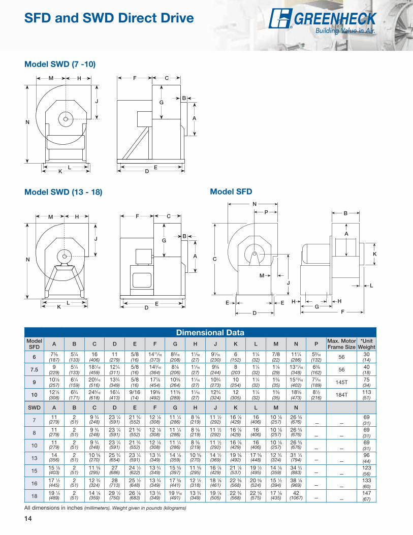
Dimensional DataModel SFD A B C D E F G H J K L M N P Max. Motor
Frame Size*Unit
Weight
6 73⁄8 (187)
51⁄4 (133)
16 (406)
11 (279)
5/8 (16)
1411⁄16 (373)
83⁄16 (208)
11⁄16 (27)
91⁄16 (230)
6 (152)
11⁄4
(32)7/8 (22)
111⁄4 (286)
53⁄16 (132) 56 30
(14)
7.5 9 (229)
51⁄4 (133)
181⁄16 (459)
121⁄4 (311)
5/8 (16)
145⁄16 (364)
81⁄8 (206)
11⁄16 (27)
95⁄8 (244)
8 (203
11⁄4
(32)11⁄8 (29)
1311⁄16 (348)
63⁄8 (162) 56 40
(18)
9 101⁄8 (257)
61⁄4
(159)205⁄16 (516)
133⁄4 (349)
5/8 (16)
177⁄8 (454)
103⁄8 (264)
11⁄16 (27)
103⁄4 (273)
10 (254)
11⁄4 (32)
13⁄8 (35)
1513⁄16 (402)
77⁄16 (189) 145T 75
(34)
10 121⁄8 (308)
63⁄4 (171)
245⁄16 (618)
161⁄4
(413)9/16 (14)
193⁄8 (492)
113⁄8 (289)
11⁄16 (27)
123⁄4 (324)
12 (305)
11⁄4 (32)
13⁄8 (35)
185⁄8 (473)
81⁄2
(216) 184T 113 (51)
SWD A B C D E F G H J K L M N
7 11 2 9 3⁄4 23 1⁄4 21 3⁄4 12 1⁄8 11 1⁄4 8 5⁄8 11 1⁄2 16 7⁄8 16 10 1⁄8 26 5⁄8 69(279) (51) (248) (591) (552) (308) (286) (219) (292) (429) (406) (257) (676) — — (31)
8 11 2 9 3⁄4 23 1⁄4 21 3⁄4 12 1⁄8 11 1⁄4 8 5⁄8 11 1⁄2 16 7⁄8 16 10 1⁄8 26 5⁄8 69(279) (51) (248) (591) (552) (308) (286) (219) (292) (429) (406) (257) (676) — — (31)
10 11 2 9 3⁄4 23 1⁄4 21 3⁄4 12 1⁄8 11 1⁄4 8 5⁄8 11 1⁄2 16 7⁄8 16 10 1⁄8 26 5⁄8 69(279) (51) (248) (591) (552) (308) (286) (219) (292) (429) (406) (257) (676) — — (31)
13 14 2 10 5⁄8 25 3⁄4 23 1⁄4 13 3⁄4 14 1⁄8 10 5⁄8 14 1⁄2 19 3⁄8 17 5⁄8 12 3⁄4 31 1⁄4 96(356) (51) (270) (654) (591) (349) (359) (270) (369) (492) (448) (324) (794) — — (44)
15 15 7⁄8 2 11 5⁄8 27 24 1⁄2 13 3⁄4 15 5⁄8 11 5⁄8 16 7⁄8 21 1⁄8 19 1⁄2 14 1⁄8 34 3⁄4 123(403) (51) (295) (686) (622) (349) (397) (295) (429) (537) (495) (359) (883) — — (56)
16 17 1⁄2 2 12 3⁄4 28 25 1⁄2 13 3⁄4 17 3⁄8 12 1⁄2 18 1⁄8 22 3⁄8 20 5⁄8 15 1⁄2 38 1⁄8 133(445) (51) (324) (713) (648) (349) (441) (318) (461) (568) (524) (394) (969) — — (60)
18 19 1⁄4 2 14 1⁄8 29 1⁄2 26 7⁄8 13 3⁄4 19 5⁄16 13 3⁄4 19 7⁄8 22 3⁄8 22 5⁄8 17 1⁄8 42 147(489) (51) (359) (750) (683) (349) (491) (349) (505) (568) (575) (435) (1067) — — (67)
H
G
F
L
A
K
J
M
P
N
C
E E
D
B
H
A
B
C
D
E
FG
H
J
K
L
M
N
P
E H
B
CF
ED
G
A
M H
J
KL
N
B
CF
ED
G
A
H
J
M
N
KL
Model SWD (7 -10)
Model SWD (13 - 18) Model SFD
All dimensions in inches (millimeters). Weight given in pounds (kilograms)
SFD and SWD Direct Drive

15
Model SFD Direct Drive
Motor HP
Fan RPM
Static Pressure in Inches wg0.125 0.25 0.375 0.5 0.75 1 1.25 1.5 2 2.5
6
6BVG
1/4
1/6 1140CFM 407 338 232BHP 0.06 0.05 0.03
Sones 6.7 6.0 4.7
4A 1/4 1725CFM 667 628 585 541 424BHP 0.24 0.22 0.20 0.17 0.13
Sones 13.6 12.8 12.3 11.7 10.5
7.5
6BVG
1/2
1/6 1140CFM 672 612 549 467BHP 0.16 0.14 0.13 0.10
Sones 10.6 9.8 9.4 8.6
5A 1/2 1725CFM 1062 1028 988 949 869 775 636BHP 0.59 0.56 0.53 0.50 0.46 0.38 0.30
Sones 20 18.6 16.8 15.8 14.1 12.7 11.3
9
4C 1/4 860CFM 839 748 645 487BHP 0.18 0.15 0.12 0.09
Sones 9.2 7.8 7.0 6.6
5B 1/2 1140CFM 1159 1097 1028 957 782BHP 0.46 0.42 0.38 0.34 0.26
Sones 16.1 14.9 14.3 13.6 12.3
15A 11⁄2 1725CFM 1806 1765 1725 1683 1595 1502 1407 1298 989BHP 1.64 1.59 1.54 1.48 1.36 1.24 1.13 1.01 0.70
Sones 31 29 28 27 25 22 21 21 19.3
10
3C 1/3 860CFM 1259 1176 1085 965BHP 0.36 0.32 0.29 0.25
Sones 12.3 11.3 10.0 9.2
7B 3/4 1140CFM 1713 1653 1592 1528 1378 1163BHP 0.86 0.82 0.77 0.72 0.64 0.52
Sones 19.4 18.5 17.6 17.0 15.7 13.9
30A 3 1725CFM 2641 2603 2564 2525 2444 2362 2275 2179 1942 1621BHP 3.03 2.98 2.93 2.87 2.73 2.60 2.44 2.32 2.01 1.62
Sones 39 37 36 35 33 31 30 29 27 25
Performance certified is for installation Type B - Free inlet, Ducted outlet. Performance ratings do not include the effects of appurtenances (accessories). The AMCA Certified Ratings Seal applies to air performance only.
International (See CAPS for performance)K = 950 RPM J = 1475 RPM
Motor RPM (Direct Drive only)
A = 1725 D = 1550B = 1140 E = 1050C = 860 G = 1300 VG = Vari-Green
Model Number CodeThe model number code is designed to completely identify the fan. The correct code letters must be specified to designate the correct construction. The remainder of the model number is determined by the size and performance.
DriveB - Belt D - Direct Discharge Position
UB - Upblast TAU - Top Angular Upblast TH - Top Horizontal TAD - Top Angular Downblast DB - Downblast BAD - Backward Angular Downblast BH - Backward Horizontal BAU - Backward Angular Upblast
Wheel RotationCW - ClockwiseCCW - Counterclockwise
Series (SWB Only)100 - Galvanized Construction200 - PermatectorTM Coated Steel Construction
Wheel TypeSW - Backward-Incline SF - Forward-Curved
Fan Size 06 through 30
SW B - 1 10 - 3 - CW - TH
Motor HP4 = 1/4 15 = 11⁄2 100 = 103 = 1/3 20 = 2 150 = 155 = 1/2 30 = 3 200 = 207 = 3/4 50 = 510 = 1 75 = 71⁄2
Model SFD Wheel Diameter Outlet Area6 6-5/16 (160) 0.27 (0.03)
7.5 7-2/3 (195) 0.33 (0.03)9 9-1/8 (232) 0.44 (0.04)10 10-3/4 (273) 0.57 (0.05)
SFD dimensional drawings found on page 14.
SFD - Direct Drive

16
Model SWD
VG Motor HP
Fan RPM
Static Pressure in Inches wg0.25 0.5 0.75 1 1.25 1.5 1.75 2 2.25 2.5
7
1/4 1725CFM 535 493 437 380 308BHP 0.16 0.17 0.17 0.17 0.17
Sones 12.4 11.6 10.8 11.1 10.6
1/2 2500CFM 802 778 750 721 689 648 603 566 523 477BHP 0.49 0.5 0.51 0.51 0.52 0.52 0.52 0.52 0.52 0.52
Sones 23 22 22 21 21 20 19.8 19.3 18.8 18.2
8
1/4 1725CFM 713 630 534 405BHP 0.14 0.15 0.15 0.15
Sones 10.5 10.2 9.5 9
1/2 2500CFM 1092 1039 984 926 864 796 716 625 520BHP 0.4 0.42 0.43 0.45 0.45 0.46 0.45 0.45 0.46
Sones 17.6 17.4 17.1 16.6 16.2 15.5 14.8 14.2 14
10
1/4 1725CFM 1283 1168 1047 921 785BHP 0.26 0.27 0.27 0.27 0.27
Sones 14.7 13.6 12.7 12 11.5
3/4 2200CFM 1691 1602 1512 1422 1324 1226 1123 1018 882BHP 0.54 0.55 0.55 0.56 0.56 0.56 0.56 0.55 0.55
Sones 21 19.7 18.9 18.2 17.4 16.6 15.5 14.6 14.9
13
1/4 1200CFM 1382 1191 964BHP 0.18 0.19 0.19
Sones 9.3 8.9 8.6
1/2 1550CFM 1874 1739 1591 1427 1246BHP 0.38 0.39 0.41 0.41 0.4
Sones 13.6 13 12.3 11.5 11
3/4 1725CFM 2115 1995 1870 1731 1581 1419 1230BHP 0.52 0.53 0.55 0.56 0.57 0.56 0.54
Sones 16 15.6 14.9 14.2 13.6 12.9 12.5
15
1/2 1150CFM 1905 1671 1416BHP 0.28 0.29 0.29
Sones 10.5 9.9 9.2
3/4 1400CFM 2412 2224 2027 1818 1605BHP 0.51 0.51 0.52 0.52 0.52
Sones 14 13.2 12.5 11.8 11.2
1 1725CFM 3053 2896 2746 2592 2422 2252 2080 1906BHP 0.93 0.95 0.96 0.97 0.98 0.98 0.97 0.96
Sones 19.5 19 18.2 17.5 16.8 16 15.2 14.7
16
3/4 900CFM 2054 1754 1394BHP 0.25 0.26 0.26
Sones 8.8 8 7
1 1300CFM 3173 2983 2795 2573 2328 2078BHP 0.72 0.75 0.77 0.79 0.79 0.78
Sones 16.1 15.3 14.6 13.8 13.1 12.6
2 1725CFM 4324 4176 4033 3890 3748 3593 3422 3241 3052 2863BHP 1.65 1.7 1.73 1.76 1.79 1.82 1.85 1.85 1.84 1.83
Sones 26 24 24 23 22 21 21 20 19.7 18.9
18
3/4 850CFM 2880 2510 2060BHP 0.39 0.4 0.39
Sones 9.8 9 8.2
1 950CFM 3302 2964 2631 2162BHP 0.54 0.55 0.56 0.54
Sones 11.9 11 10.1 9.6
2 1300CFM 4734 4487 4240 3994 3765 3496 3157BHP 1.37 1.39 1.41 1.43 1.44 1.43 1.4
Sones 20 19.7 19.2 18.4 17.6 17 16.6
Performance certified is for installation Type B - Free inlet, Ducted outlet. Performance ratings do not include the effects of appurtenances (accessories). The AMCA Certified Ratings Seal applies to air performance only.
Model SWD Wheel Diameter Outlet Area7 11-3/8 (289) 0.76 (0.07)8 11-3/8 (289) 0.76 (0.07)10 11-3/8 (289) 0.76 (0.07)13 13-1/2 (343) 1.03 (0.10)15 14-3/4 (375) 1.25 (0.12)16 17 (432) 1.52 (0.14)18 19 (483) 1.87 (0.17)
SWD dimensional drawings found on page 14.
SWD - Vari-Green®

17
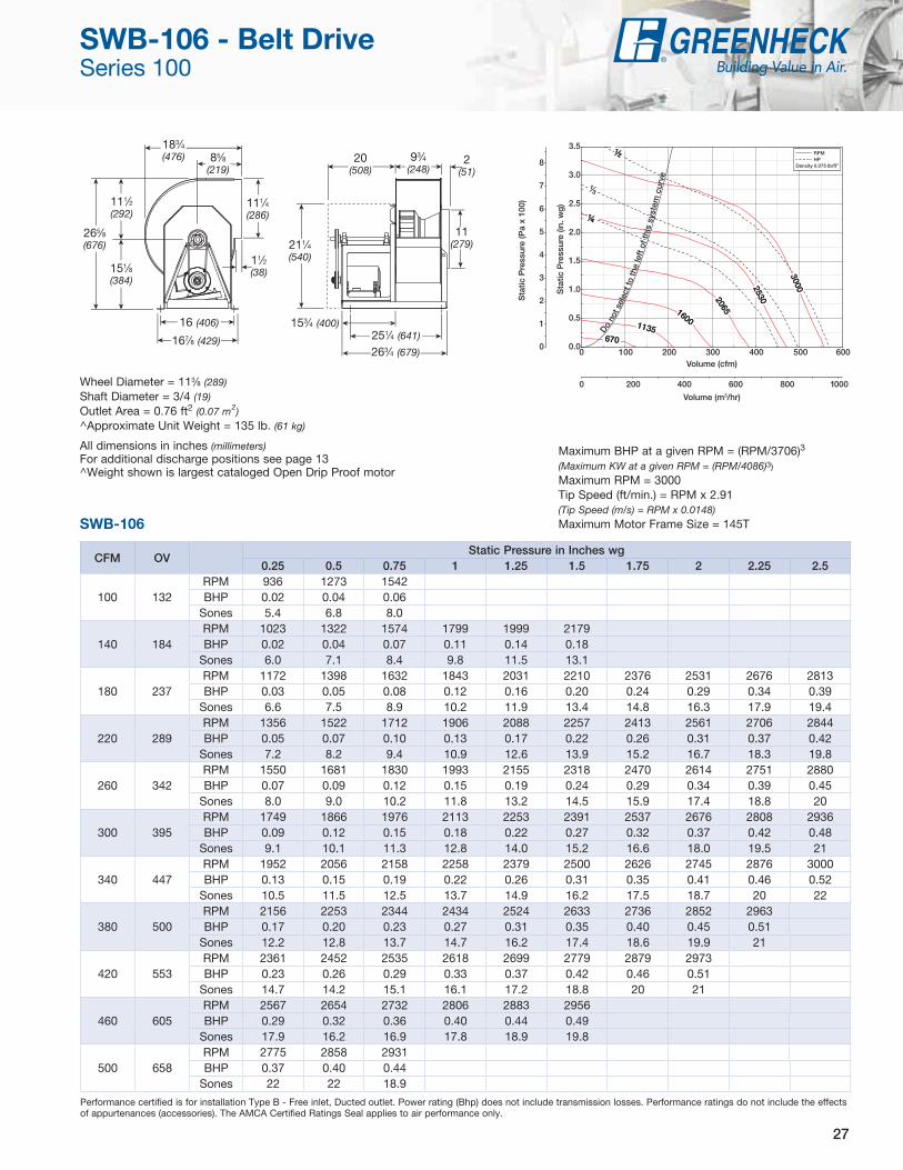
Wheel Diameter = 91⁄2 (241)Shaft Diameter = 3/4 (19)Outlet Area = 0.454 ft2 (0.042 m2)^Approximate Unit Weight = 120 lb. (54 kg)
All dimensions in inches (millimeters)For additional discharge positions see page 12^Weight shown is largest cataloged Open Drip Proof motor
CFM OVStatic Pressure in Inches wg
0.25 0.5 0.75 1 1.25 1.5 1.75 2 2.25 2.5
360 792RPM 644BHP 0.03
Sones 6.3
460 1013RPM 681 891BHP 0.05 0.08
Sones 6.8 11.0
560 1233RPM 728 930 1090 1225BHP 0.07 0.11 0.15 0.19
Sones 7.5 10.8 10.1 10.3
660 1453RPM 780 966 1129 1264 1382BHP 0.09 0.14 0.18 0.23 0.28
Sones 8.5 10.7 10.3 10.6 11.0
760 1674RPM 838 1013 1166 1303 1422 1528 1628BHP 0.13 0.18 0.23 0.28 0.34 0.39 0.44
Sones 9.8 10.6 10.7 11.0 11.8 13.2 14.5
860 1894RPM 909 1064 1207 1340 1461 1568 1667 1758 1845BHP 0.17 0.23 0.28 0.34 0.40 0.46 0.52 0.58 0.64
Sones 11.1 10.9 11.1 11.4 12.6 14.0 15.4 17.0 18.6
960 2114RPM 983 1118 1256 1378 1498 1608 1706 1798 1883 1965BHP 0.23 0.28 0.34 0.40 0.47 0.54 0.61 0.68 0.75 0.82
Sones 11.1 11.5 11.8 12.1 13.4 14.9 16.4 18.0 19.7 21
1060 2334RPM 1059 1174 1306 1426 1534 1644 1745 1837 1923BHP 0.30 0.35 0.42 0.49 0.55 0.63 0.71 0.78 0.86
Sones 12.0 12.2 12.6 13.2 14.3 15.8 17.5 19.1 21
1260 2775RPM 1216 1318 1417 1528 1631 1728 1818 1911 1999BHP 0.48 0.54 0.61 0.69 0.77 0.84 0.92 1.01 1.10
Sones 14.2 14.3 14.6 15.7 16.8 18.1 19.5 21 23
1360 2995RPM 1297 1392 1482 1583 1682 1777 1866 1949BHP 0.59 0.66 0.72 0.81 0.89 0.98 1.06 1.14
Sones 15.7 15.7 16.1 17.0 18.1 19.5 21 22
1460 3215RPM 1378 1468 1554 1639 1736 1827 1915 1998BHP 0.71 0.79 0.86 0.94 1.03 1.13 1.22 1.31
Sones 17.3 17.2 17.6 18.3 19.6 21 22 24
Performance certified is for installation Type B - Free inlet, Ducted outlet. Power rating (Bhp) does not include transmission losses. Performance ratings do not include the effects of appurtenances (accessories). The AMCA Certified Ratings Seal applies to air performance only.
197⁄8 (505)
151⁄2 (394)
65⁄8 (168)
2 (51)
10 (254)
115⁄16 (287)
20 (508)
101⁄8 (257)
15⁄8 (41)
141⁄4 (362)
133⁄4 (349)
24 (610)
101⁄4 (260)
8 (203)
167⁄8 (429)
131⁄2 (343)
Do n
ot s
elec
t to
the
left
of th
is s
yste
m c
urve
cfm
Maximum BHP at given RPM = (RPM/1747)3
(Maximum KW at a given RPM = (RPM/1926)3)Maximum RPM = 2000 and Minimum RPM = 450Tip Speed (ft/min.) = RPM x 2.49(Tip Speed (m/s) = RPM x 0.0126)Maximum Motor Frame Size = 145TSFB-9
SFB-9 - Belt Drive

18
CFM OVStatic Pressure in Inches wg
0.25 0.5 0.75 1 1.25 1.5 1.75 2 2.25 2.5
600 851RPM 526BHP 0.05
Sones 5.6
790 1121RPM 575 730BHP 0.08 0.12
Sones 6.2 9.1
980 1390RPM 633 777 897 1013BHP 0.13 0.18 0.23 0.30
Sones 7.1 10.3 10.3 10.2
1170 1660RPM 693 828 944 1045 1144BHP 0.19 0.25 0.32 0.38 0.45
Sones 8.3 10.7 10.3 10.6 10.9
1360 1930RPM 760 887 994 1092 1181 1263 1349 1430BHP 0.27 0.35 0.42 0.50 0.57 0.64 0.73 0.81
Sones 9.9 10.7 10.7 11.0 11.3 12.0 13.3 14.7
1550 2199RPM 828 946 1049 1142 1229 1309 1383 1456 1531 1603BHP 0.37 0.46 0.54 0.63 0.73 0.81 0.89 0.97 1.02 1.17
Sones 11.1 11.0 11.3 11.6 12.0 13.0 14.2 15.5 17.0 18.7
1740 2469RPM 898 1009 1109 1196 1279 1357 1430 1499 1564 1629BHP 0.50 0.60 0.70 0.79 0.89 1.00 1.09 1.18 1.27 1.37
Sones 11.4 11.7 12.1 12.4 13.1 14.2 15.5 16.8 18.1 19.9
1930 2739RPM 973 1077 1169 1256 1332 1407 1479 1546 1611BHP 0.66 0.77 0.87 0.99 1.08 1.20 1.32 1.43 1.53
Sones 12.4 12.7 13.0 13.6 14.5 15.6 16.8 18.1 19.8
2120 3008RPM 1050 1145 1232 1316 1393 1461 1529 1596BHP 0.85 0.97 1.09 1.21 1.33 1.43 1.56 1.69
Sones 13.8 13.9 14.1 15.0 16.0 17.1 18.3 19.8
2310 3278RPM 1128 1214 1299 1376 1452 1522 1585 1647BHP 1.08 1.21 1.34 1.46 1.59 1.72 1.84 1.97
Sones 15.3 15.2 15.6 16.5 17.6 18.8 20 22
2500 3548RPM 1207 1285 1368 1441 1512 1581 1645BHP 1.36 1.48 1.63 1.76 1.90 2.04 2.18
Sones 17.1 16.9 17.4 18.3 19.4 21 22
Performance certified is for installation Type B - Free inlet, Ducted outlet. Power rating (Bhp) does not include transmission losses. Performance ratings do not include the effects of appurtenances (accessories). The AMCA Certified Ratings Seal applies to air performance only.
Do not s
elec
t to
the
left
of th
is s
yste
m c
urve
cfmWheel Diameter = 105⁄8 (270)Shaft Diameter = 3/4 (19)Outlet Area = 0.705 ft2 (0.065 m2)^Approximate Unit Weight = 130 lb. (59 kg)
All dimensions in inches (millimeters)For additional discharge positions see page 12^Weight shown is largest cataloged Open Drip Proof motor
221⁄4 (565)
151⁄2 (394)
81⁄2 (216)
2 (51)
11 (279)
12 (305)203⁄8 (518)
22 (559)
193⁄8 (492)
113⁄4 (298)
21⁄4 (57)
16 (406)
167⁄8 (429)
265⁄8 (676)
111⁄2 (292)
91⁄4 (235)
151⁄8 (384)
Maximum BHP at given RPM = (RPM/1310)3
(Maximum KW at a given RPM = (RPM/1444)3)Maximum RPM = 1650 and Minimum RPM = 400Tip Speed (ft/min.) = RPM x 2.78(Tip Speed (m/s) = RPM x 0.0141)Maximum Motor Frame Size = 145TSFB-10
SFB-10 - Belt Drive

19
CFM OVStatic Pressure in Inches wg
0.25 0.5 0.75 1 1.25 1.5 1.75 2 2.25 2.5
825 964RPM 455BHP 0.07
Sones 5.7
1065 1244RPM 493 631BHP 0.12 0.18
Sones 6.3 9.3
1305 1525RPM 533 665 773 871BHP 0.18 0.25 0.33 0.40
Sones 7.1 10.2 10.3 10.5
1545 1805RPM 580 703 806 897 983 1061BHP 0.26 0.35 0.43 0.52 0.62 0.71
Sones 8.2 10.5 10.6 11.0 11.3 12.0
1785 2086RPM 632 743 844 931 1010 1087 1158 1225BHP 0.36 0.47 0.57 0.67 0.77 0.88 0.99 1.09
Sones 9.6 10.7 11.1 11.5 11.8 13.0 14.4 16.0
2025 2367RPM 686 789 883 969 1045 1116 1185 1251 1313 1373BHP 0.49 0.61 0.74 0.85 0.96 1.07 1.19 1.32 1.44 1.56
Sones 11.0 11.4 11.8 12.2 12.7 14.0 15.5 17.0 18.6 20
2265 2647RPM 747 837 925 1008 1083 1152 1217 1278 1340 1399BHP 0.67 0.79 0.93 1.06 1.19 1.31 1.44 1.56 1.70 1.84
Sones 11.8 12.2 12.6 12.9 13.9 15.2 16.6 18.1 19.8 22
2505 2928RPM 809 889 971 1048 1122 1190 1254 1314 1370BHP 0.88 1.00 1.15 1.30 1.45 1.59 1.73 1.87 2.00
Sones 13.0 13.2 13.5 14.1 15.3 16.6 17.9 19.5 21
2745 3208RPM 873 943 1019 1093 1162 1230 1292BHP 1.13 1.26 1.41 1.58 1.75 1.91 2.06
Sones 14.5 14.4 14.6 15.6 16.7 18.0 19.5
2985 3489RPM 937 1001 1071 1140 1205BHP 1.43 1.56 1.72 1.90 2.08
Sones 16.1 15.8 16.2 17.1 18.2
3225 3769RPM 1002 1062 1124BHP 1.77 1.92 2.08
Sones 17.8 17.4 17.8
Performance certified is for installation Type B - Free inlet, Ducted outlet. Power rating (Bhp) does not include transmission losses. Performance ratings do not include the effects of appurtenances (accessories). The AMCA Certified Ratings Seal applies to air performance only.
Wheel Diameter = 125⁄8 (321)Shaft Diameter = 3/4 (19)Outlet Area = 0.856 ft2 (0.08 m2)^Approximate Unit Weight = 147 lb. (67 kg)
All dimensions in inches (millimeters)For additional discharge positions see page 12^Weight shown is largest cataloged Open Drip Proof motor
Do not s
elec
t to
the
left
of th
is s
yste
m c
urve
cfm
135⁄8 (346)
11⁄2 (38)
16 (406)
167⁄8 (429)
151⁄8 (384)
283⁄8 (721)
131⁄4 (337)
93⁄4 (248)
213⁄8 (543)
221⁄4 (565)
151⁄2 (394)
9 (229)
2 (51)
13 (330)
12 (305)207⁄8 (530)
221⁄2 (572)
Maximum BHP at given RPM = (RPM/1111)3
(Maximum KW at a given RPM = (RPM/1225)3)Maximum RPM = 1400 and Minimum RPM = 370Tip Speed (ft/min.) = RPM x 3.30(Tip Speed (m/s) = RPM x 0.0168)Maximum Motor Frame Size = 145TSFB-12
SFB-12 - Belt Drive

20
CFM OVStatic Pressure in Inches wg
0.25 0.5 0.75 1 1.25 1.5 1.75 2 2.5 2.75
1560 1125RPM 395 508BHP 0.16 0.25
Sones 6.0 8.1
1860 1342RPM 421 529 619BHP 0.23 0.33 0.43
Sones 7.5 8.8 9.4
2160 1558RPM 450 554 638 716BHP 0.32 0.44 0.55 0.67
Sones 9.9 9.6 10.3 11.2
2460 1775RPM 481 580 663 734 803 865BHP 0.42 0.56 0.70 0.83 0.97 1.09
Sones 10.9 10.6 11.4 12.0 13.4 15.2
2760 1991RPM 514 608 688 759 822 884 941BHP 0.56 0.71 0.87 1.03 1.17 1.32 1.47
Sones 11.5 11.9 12.3 12.8 14.0 15.6 17.2
3060 2208RPM 549 637 715 784 846 903 959 1013BHP 0.72 0.89 1.07 1.24 1.41 1.57 1.74 1.90
Sones 12.7 13.5 13.2 13.5 14.6 16.0 17.5 19.0
3360 2424RPM 585 668 742 810 871 928 980 1031 1128 1174BHP 0.91 1.11 1.29 1.49 1.68 1.87 2.04 2.22 2.58 2.75
Sones 14.1 14.9 14.0 14.1 15.0 16.5 17.9 19.4 22 24
3660 2641RPM 623 701 772 837 897 953 1005 1053 1147 1192BHP 1.14 1.35 1.56 1.76 1.98 2.18 2.39 2.58 2.98 3.17
Sones 15.9 16.0 14.7 14.7 15.4 17.0 18.6 20 23 24
3960 2857RPM 662 734 802 865 924 979 1030 1078 1166BHP 1.41 1.63 1.86 2.07 2.31 2.54 2.76 2.98 3.40
Sones 17.8 17.3 15.9 15.4 16.3 17.7 19.3 21 23
4260 3074RPM 701 768 834 895 951 1005 1056 1103 1191BHP 1.71 1.95 2.20 2.44 2.67 2.93 3.17 3.41 3.88
Sones 18.9 18.6 17.2 16.6 17.6 18.9 20 22 24
4560 3290RPM 742 804 867 925 980 1032 1082 1129BHP 2.06 2.32 2.59 2.85 3.09 3.35 3.63 3.89
Sones 20 19.8 18.8 18.4 19.2 20 22 23
Performance certified is for installation Type B - Free inlet, Ducted outlet. Power rating (Bhp) does not include transmission losses. Performance ratings do not include the effects of appurtenances (accessories). The AMCA Certified Ratings Seal applies to air performance only.
Wheel Diameter = 15 (381)Shaft Diameter = 1 (25)Outlet Area = 1.39 ft2 (0.129 m2)Mounting Hole Size = 1/2 (13)^Approximate Unit Weight = 214 lb. (97 kg)
All dimensions in inches (millimeters)For additional discharge positions see page 12^Weight shown is largest cataloged Open Drip Proof motor
Do no
t sel
ect t
o th
e le
ft of
this
sys
tem
cur
ve
cfm
243⁄4 (629)
213⁄4 (552)
123⁄4 (324)
2 (51)
153⁄8 (391)
13 (330)30 (762)
325⁄8 (829)
233⁄8 (594)
16 (406)
11⁄2 (38)
187⁄8 (479)
165⁄8 (422)
311⁄4 (371)
145⁄8 (371)
105⁄8 (270)
175⁄8 (448)
Maximum BHP at given RPM = (RPM/720)3
(Maximum KW at a given RPM = (RPM/794)3)Maximum RPM = 1200 and Minimum RPM = 380Tip Speed (ft/min.) = RPM x 3.93(Tip Speed (m/s) = RPM x 0.0200)Maximum Motor Frame Size = 184TSFB-15
SFB-15 - Belt Drive

21
CFM OVStatic Pressure in Inches wg
0.25 0.5 0.75 1 1.25 1.5 1.75 2 2.25 2.5
2725 1188RPM 364 464 550BHP 0.29 0.44 0.60
Sones 8.4 9.2 10.2
3150 1374RPM 388 481 563 635BHP 0.39 0.56 0.74 0.93
Sones 10.3 10.1 11.2 12.6
3575 1559RPM 415 500 578 648 712BHP 0.52 0.70 0.90 1.11 1.33
Sones 11.1 11.3 12.2 13.4 15.5
4000 1744RPM 444 524 596 662 725 782 836BHP 0.68 0.89 1.10 1.32 1.56 1.80 2.03
Sones 12.0 13.1 13.1 14.0 15.8 17.7 19.5
4425 1930RPM 473 548 615 680 738 795 848 898 943BHP 0.87 1.09 1.32 1.57 1.81 2.08 2.34 2.60 2.86
Sones 13.6 14.7 14.0 14.4 15.9 17.8 19.7 21 23
4850 2115RPM 503 573 638 698 756 809 861 910 957 1001BHP 1.09 1.34 1.59 1.85 2.12 2.38 2.68 2.97 3.26 3.54
Sones 15.5 15.8 14.8 14.8 16.2 18.1 20 22 24 25
5275 2300RPM 534 601 662 719 774 826 875 923 970 1013BHP 1.36 1.63 1.90 2.17 2.46 2.75 3.04 3.35 3.67 3.99
Sones 17.7 17.1 15.6 15.6 16.7 18.7 20 22 24 26
5700 2486RPM 566 630 687 743 793 844 893 938 982 1026BHP 1.67 1.96 2.24 2.55 2.83 3.15 3.47 3.78 4.11 4.46
Sones 19.2 18.6 16.9 16.6 17.9 19.5 21 23 25 26
6125 2671RPM 599 660 714 767 817 863 911 956 998 1039BHP 2.03 2.34 2.64 2.96 3.28 3.58 3.94 4.28 4.61 4.95
Sones 20 20 18.5 18.0 19.4 21 22 24 26 27
6550 2857RPM 631 689 743 791 840 886 929 974 1016BHP 2.43 2.76 3.09 3.41 3.77 4.10 4.43 4.81 5.18
Sones 22 21 20 20 21 22 24 26 27
6975 3042RPM 664 720 771 818 865 909 951 992 1034BHP 2.88 3.23 3.60 3.93 4.30 4.67 5.02 5.38 5.78
Sones 24 23 23 22 23 24 26 27 29
Performance certified is for installation Type B - Free inlet, Ducted outlet. Power rating (Bhp) does not include transmission losses. Performance ratings do not include the effects of appurtenances (accessories). The AMCA Certified Ratings Seal applies to air performance only.
Wheel Diameter = 181⁄8 (460)Shaft Diameter = 1 (25)Outlet Area = 2.29 ft2 (0.213 m2)Mounting Hole Size = 1/2 (13)^Approximate Unit Weight = 265 lb. (120 kg)
All dimensions in inches (millimeters)For additional discharge positions see page 12^Weight shown is largest cataloged Open Drip Proof motor
Do not
sel
ect t
o th
e le
ft of
this
sys
tem
cur
ve
cfm
307⁄8 (784)
193⁄8 (492)
11⁄2 (38)
233⁄8 (594)
251⁄8 (638)
223⁄8 (568)
42 (1067)
195⁄8 (498)
133⁄4 (349)
331⁄4 (845)
22 (559)
173⁄4 (451) 2
(51)
191⁄4 (489)
18 (457)35 (889)
367⁄8 (937)
Maximum BHP at given RPM = (RPM/614)3
(Maximum KW at a given RPM = (RPM/677)3)Maximum RPM = 1050 and Minimum RPM = 310Tip Speed (ft/min.) = RPM x 4.75(Tip Speed (m/s) = RPM x 0.0241)Maximum Motor Frame Size = 184TSFB-18
SFB-18 - Belt Drive

22
CFM OVStatic Pressure in Inches wg
0.25 0.5 0.75 1 1.25 1.5 1.75 2 2.5 2.75
3275 1362RPM 320 402BHP 0.37 0.53
Sones 8.1 9.1
3800 1581RPM 343 420 487BHP 0.51 0.70 0.90
Sones 10.3 10.1 11.3
4325 1799RPM 369 440 503 561 613BHP 0.70 0.90 1.13 1.36 1.61
Sones 11.3 11.5 12.6 13.1 14.6
4850 2018RPM 396 462 521 576 628 676BHP 0.92 1.15 1.39 1.64 1.91 2.19
Sones 12.3 13.4 13.7 13.9 15.0 16.7
5375 2236RPM 424 485 542 594 642 689 733BHP 1.19 1.45 1.71 1.99 2.26 2.56 2.87
Sones 14.0 15.4 14.7 14.5 15.3 16.9 18.6
5900 2455RPM 454 511 564 614 661 704 747 788BHP 1.52 1.80 2.08 2.38 2.68 2.98 3.30 3.64
Sones 16.1 16.8 15.5 15.3 15.5 17.3 19.0 21
6425 2673RPM 484 537 587 634 679 722 762 801 877 911BHP 1.90 2.22 2.52 2.83 3.15 3.49 3.81 4.15 4.89 5.26
Sones 18.6 18.4 16.8 16.1 16.5 18.0 19.8 21 24 26
6950 2892RPM 515 565 612 657 700 741 780 818 890 925BHP 2.36 2.69 3.02 3.36 3.70 4.04 4.41 4.76 5.51 5.92
Sones 20 19.8 18.5 17.0 18.0 19.3 21 22 25 26
7475 3110RPM 546 593 638 681 722 761 799 836 904 938BHP 2.88 3.24 3.59 3.95 4.30 4.68 5.05 5.44 6.20 6.61
Sones 22 21 20 19.2 19.5 21 22 24 27 28
8000 3329RPM 578 622 665 705 745 782 819 854 922BHP 3.47 3.86 4.24 4.61 5.00 5.38 5.79 6.18 7.02
Sones 24 23 22 22 22 23 24 25 29
8525 3547RPM 610 652 692 731 769 805 840 875 940BHP 4.14 4.55 4.96 5.37 5.77 6.18 6.59 7.02 7.89
Sones 26 24 24 24 24 25 26 28 31
Performance certified is for installation Type B - Free inlet, Ducted outlet. Power rating (Bhp) does not include transmission losses. Performance ratings do not include the effects of appurtenances (accessories). The AMCA Certified Ratings Seal applies to air performance only.
Wheel Diameter = 20 (508)Shaft Diameter = 11⁄4 (32)Outlet Area = 2.40 ft2 (0.223 m2)Mounting Hole Size = 5/8 (16)^Approximate Unit Weight = 405 lb (184 kg)
All dimensions in inches (millimeters)For additional discharge positions see page 12^Weight shown is largest cataloged Open Drip Proof motor
Do not se
lect
to th
e le
ft of
this
sys
tem
cur
ve
cfm
361⁄8 (918)
233⁄4 (603)
157⁄8 (403) 2
(51)
211⁄8 (537)
191⁄2 (495)35 (889)
37 (940)
335⁄8 (854)
22 (559)
11⁄2 (38)
273⁄8 (695)
241⁄2 (622)
46 (1168)
211⁄2 (546)
147⁄8 (378)
255⁄8 (651)
Maximum BHP at given RPM = (RPM/485)3
(Maximum KW at a given RPM = (RPM/535)3)Maximum RPM = 950 and Minimum RPM = 270Tip Speed (ft/min.) = RPM x 5.24(Tip Speed (m/s) = RPM x 0.0266)Maximum Motor Frame Size = 215TSFB-20
SFB-20 - Belt Drive

23
CFM OVStatic Pressure in Inches wg
0.25 0.5 0.75 1 1.25 1.5 2 2.5 3 3.25
4000 1240RPM 285 359 419BHP 0.44 0.64 0.83
Sones 8.6 10.5 12.8
4950 1534RPM 315 385 441 491 535BHP 0.71 0.96 1.20 1.43 1.67
Sones 11.3 13 15.4 16.6 18
5900 1829RPM 350 410 467 514 557 598BHP 1.09 1.37 1.68 1.96 2.23 2.52
Sones 14.1 15.9 17.9 19 20 22
6850 2123RPM 388 441 491 540 582 620 691 755BHP 1.60 1.91 2.25 2.61 2.95 3.26 3.92 4.56
Sones 17.2 19.3 20 22 23 24 26 29
7800 2418RPM 428 475 520 564 608 646 713 776 834 861BHP 2.25 2.61 2.98 3.37 3.79 4.17 4.88 5.64 6.38 6.75
Sones 21 22 23 25 26 28 29 31 34 36
8750 2712RPM 470 511 552 593 632 671 739 798 854 881BHP 3.08 3.47 3.87 4.30 4.75 5.21 6.08 6.87 7.71 8.14
Sones 24 25 26 28 30 30 32 34 37 39
9700 3007RPM 512 550 587 624 660 695 764 824 877BHP 4.09 4.53 4.97 5.43 5.90 6.39 7.41 8.35 9.24
Sones 27 28 30 31 32 34 36 39 41
10650 3301RPM 555 590 623 658 691 724 789 850BHP 5.33 5.80 6.27 6.77 7.28 7.79 8.90 10
Sones 30 32 34 35 36 37 40 43
11600 3596RPM 599 631 662 693 724 755 813 874BHP 6.79 7.30 7.83 8.34 8.88 9.44 10.54 11.82
Sones 34 37 38 38 39 41 44 47
12550 3890RPM 643 672 701 730 759 788 844 898BHP 8.51 9.04 9.62 10.17 10.76 11.33 12.56 13.8
Sones 38 40 42 42 43 45 48 52
13500 4185RPM 688 714 742 768 794 822 875BHP 10.5 11.1 11.7 12.3 12.9 13.5 14.8
Sones 42 44 46 47 48 49 53
Performance certified is for installation Type B - Free inlet, Ducted outlet. Power rating (Bhp) does not include transmission losses. Performance ratings do not include the effects of appurtenances (accessories). The AMCA Certified Ratings Seal applies to air performance only.
Wheel Diameter = 221⁄4 (565)Shaft Diameter = 11⁄4 (32)Outlet Area = 3.23 ft2 (0.300 m2)Mounting Hole Size = 5/8 (16)^Approximate Unit Weight = 540 lb (245 kg)
All dimensions in inches (millimeters)For additional discharge positions see page 12^Weight shown is largest cataloged Open Drip Proof motor
24 (610)
171⁄2 (445)
21⁄2 (64)
23 (584)
20 (508)341⁄8 (867)
395⁄8 (1006)
411⁄2 (1054)
363⁄4 (933)
275⁄8 (702)
11⁄2 (38)
521⁄2 (1334)
233⁄4 (603)
16 (406)
281⁄4 (718)
283⁄4 (730)
303⁄4 (781)Do n
ot s
elec
t to
the
left
of th
is s
yste
m c
urve
cfm
Maximum BHP at given RPM = (RPM/418)3
(Maximum KW at a given RPM = (RPM/461)3)
Maximum RPM = 900 and Minimum RPM = 240Tip Speed (ft/min.) = RPM x 5.79(Tip Speed (m/s) = RPM x 0.0294)Maximum Motor Frame Size = 215TSFB-22
SFB-22 - Belt Drive

24
CFM OVStatic Pressure in Inches wg
0.25 0.5 0.75 1 1.25 1.5 2 2.5 3 3.25
6000 1425RPM 246 310 363 412BHP 0.74 1.03 1.32 1.65
Sones 8.4 10.4 12.5 14.5
6950 1651RPM 263 324 375 419 463BHP 1.02 1.37 1.72 2.05 2.42
Sones 10.3 11.9 14.3 15.8 17.3
7900 1877RPM 283 338 387 431 470 508BHP 1.39 1.78 2.17 2.57 2.95 3.34
Sones 12.1 13.7 16.2 17.3 18.6 20
8850 2103RPM 304 354 401 444 482 518 585BHP 1.85 2.29 2.73 3.15 3.61 4.03 4.93
Sones 14.1 15.7 17.9 19.0 20 22 25
9800 2329RPM 326 372 416 457 495 530 593 654BHP 2.40 2.87 3.36 3.86 4.32 4.83 5.76 6.81
Sones 16.1 18.0 19.6 21 22 23 26 29
10750 2554RPM 349 391 432 471 508 542 605 660 716 743BHP 3.07 3.58 4.12 4.65 5.19 5.70 6.79 7.78 8.96 9.57
Sones 18.4 20 21 23 24 25 27 30 33 35
11700 2780RPM 373 412 450 487 522 556 617 672 722 748BHP 3.86 4.42 4.99 5.57 6.16 6.73 7.89 9.05 10.11 10.74
Sones 21 22 23 25 26 28 29 32 35 36
12650 3006RPM 397 433 468 504 537 569 629 684 734BHP 4.78 5.37 5.96 6.62 7.22 7.88 9.07 10.39 11.62
Sones 23 24 25 27 28 30 32 34 36
13600 3232RPM 421 455 488 521 553 584 643 696 746BHP 5.84 6.46 7.13 7.79 8.48 9.13 10.51 11.82 13.21
Sones 25 26 27 29 31 32 34 36 39
14550 3457RPM 445 478 510 539 570 600 657 709BHP 7.04 7.72 8.43 9.09 9.86 10.58 12.04 13.43
Sones 27 29 30 31 33 34 36 39
15500 3683RPM 471 501 531 559 588 617 671 723BHP 8.43 9.15 9.88 10.62 11.37 12.18 13.68 15.26
Sones 29 31 33 34 35 36 39 42
Performance certified is for installation Type B - Free inlet, Ducted outlet. Power rating (Bhp) does not include transmission losses. Performance ratings do not include the effects of appurtenances (accessories). The AMCA Certified Ratings Seal applies to air performance only.
Wheel Diameter = 25 (635)Shaft Diameter = 11⁄2 (38)Outlet Area = 4.21 ft2(0.391 m2)Mounting Hole Size = 5/8 (16)^Approximate Unit Weight = 700 lb. (318 kg)
All dimensions in inches (millimeters)For additional discharge positions see page 12^Weight shown is largest cataloged Open Drip Proof motor
403⁄8 (1026)
315⁄8 (803)
11⁄2 (38)
311⁄8 (791)
335⁄8 (854)
261⁄4 (667)
171⁄2 (445)
311⁄2 (800)
573⁄4 (1467) 453⁄4
(1162)
25 (635)
191⁄2 (495)
21⁄2 (64)
257⁄8 (657)
411⁄2 (1054)
197⁄8 (505)36 (914)
Do not
sel
ect t
o th
e le
ft of
this
sys
tem
cur
ve
cfm
Maximum BHP at given RPM = (RPM/304)3
(Maximum KW at a given RPM = (RPM/335)3)Maximum RPM = 750 and Minimum RPM = 190Tip Speed (ft/min.) = RPM x 6.54(Tip Speed (m/s) = RPM x 0.0332)Maximum Motor Frame Size = 284TSFB-25
SFB-25 - Belt Drive

25
CFM OVStatic Pressure in Inches wg
0.25 0.5 0.75 1 1.25 1.5 2 2.5 3 3.25
8600 1729RPM 245 297 345 388 427 462BHP 1.29 1.72 2.17 2.61 3.07 3.56
Sones 11.1 12.5 15.1 16.7 18.2 20
9750 1961RPM 264 310 355 397 434 470BHP 1.75 2.21 2.71 3.23 3.73 4.26
Sones 13.1 14.6 17.0 18.4 19.7 21
10900 2192RPM 284 327 368 407 444 477 540BHP 2.31 2.84 3.38 3.94 4.51 5.05 6.24
Sones 15.1 16.7 18.9 20 21 23 26
12050 2423RPM 305 344 381 419 454 487 547 603 652BHP 3.02 3.58 4.14 4.78 5.39 6.03 7.28 8.58 9.95
Sones 17.3 19.2 21 22 23 25 27 30 34
13200 2655RPM 327 363 398 432 465 497 556 610 660 683BHP 3.85 4.46 5.09 5.73 6.41 7.09 8.45 9.86 11.28 12.04
Sones 19.8 22 23 24 25 27 29 32 35 37
14350 2886RPM 349 382 415 447 478 508 566 618 668 691BHP 4.83 5.47 6.16 6.83 7.57 8.30 9.80 11.22 12.80 13.58
Sones 22 24 25 26 28 29 31 33 37 39
15500 3117RPM 372 403 434 464 491 521 576 628 676 699BHP 5.97 6.64 7.40 8.14 8.84 9.68 11.25 12.88 14.41 15.28
Sones 25 26 27 28 30 32 34 36 39 40
16650 3349RPM 395 424 453 481 508 535 588 638 685BHP 7.27 8.02 8.80 9.60 10.38 11.17 12.90 14.64 16.36
Sones 27 28 29 31 33 34 36 39 41
17800 3580RPM 418 446 472 499 525 550 601 648 695BHP 8.76 9.59 10.37 11.24 12.10 12.92 14.74 16.49 18.42
Sones 29 31 32 34 35 36 39 41 44
18950 3811RPM 441 468 492 518 543 567 614 661BHP 10.40 11.30 12.10 13.10 14.00 14.90 16.70 18.70
Sones 32 34 35 37 38 39 41 44
20100 4043RPM 465 490 514 538 561 585 629 674BHP 12.40 13.30 14.20 15.10 16.10 17.10 18.90 21.00
Sones 34 37 39 39 40 41 44 47
Performance certified is for installation Type B - Free inlet, Ducted outlet. Power rating (Bhp) does not include transmission losses. Performance ratings do not include the effects of appurtenances (accessories). The AMCA Certified Ratings Seal applies to air performance only.
Wheel Diameter = 271⁄2 (699)Shaft Diameter = 11⁄2 (38)Outlet Area = 4.97 ft2 (0.462 m2)Mounting Hole Size = 5/8 (16)^Approximate Unit Weight = 845 lb. (383 kg)
All dimensions in inches (millimeters)For additional discharge positions see page 12^Weight shown is largest cataloged Open Drip Proof motor
Do n
ot s
elec
t to
the
left
of th
is s
yste
m c
urve
cfm
44 (1118)
341⁄2 (876)
35⁄8 (92)
351⁄8 (892)
375⁄8 (956)
33 (838)
611⁄8 (1553)
281⁄8 (714)
19 (483)
491⁄8 (1248)
27 (686)
213⁄8 (543)
21⁄2 (64)
281⁄2 (724)
221⁄4 (565)401⁄2 (1029)
46 (1168)
Maximum BHP at given RPM = (RPM/285)3
(Maximum KW at a given RPM = (RPM/314)3)Maximum RPM = 700 and Minimum RPM = 200Tip Speed (ft/min.) = RPM x 7.20(Tip Speed (m/s) = RPM x 0.0366)Maximum Motor Frame Size = 286TSFB-27
SFB-27 - Belt Drive

26
CFM OVStatic Pressure in Inches wg
0.25 0.5 0.75 1 1.25 1.5 2 2.5 3 3.25
10000 1749RPM 245 293 332 369 403 434BHP 1.60 2.12 2.59 3.13 3.63 4.19
Sones 13.0 15.0 17.3 18.6 20 22
11525 2015RPM 267 311 350 383 416 446 501BHP 2.25 2.85 3.44 3.98 4.60 5.19 6.43
Sones 15.7 17.9 19.7 21 22 24 27
13050 2282RPM 291 330 368 401 430 459 513 562 606BHP 3.10 3.73 4.44 5.09 5.69 6.39 7.73 9.15 10.56
Sones 18.7 21 22 24 25 27 29 32 35
14575 2549RPM 316 352 387 419 448 474 526 573 617 638BHP 4.14 4.85 5.60 6.37 7.10 7.78 9.31 10.79 12.37 13.16
Sones 22 23 25 27 28 30 31 34 38 40
16100 2816RPM 342 375 406 437 466 492 539 586 629 649BHP 5.42 6.18 6.96 7.84 8.69 9.49 11.02 12.74 14.38 15.20
Sones 25 26 28 30 32 33 35 37 40 42
17625 3082RPM 369 399 428 456 484 510 557 600 642BHP 6.98 7.78 8.64 9.51 10.49 11.40 13.12 14.86 16.73
Sones 28 29 31 33 35 36 38 41 44
19150 3349RPM 397 423 450 477 503 529 575 616BHP 8.82 9.65 10.57 11.50 12.50 13.55 15.51 17.32
Sones 31 33 35 36 38 39 42 45
20675 3616RPM 424 448 474 499 523 547 593 634BHP 11.00 11.80 12.80 13.80 14.80 15.90 18.10 20.20
Sones 35 37 39 40 41 43 46 49
22200 3883RPM 452 474 498 521 545 566 612BHP 13.40 14.30 15.40 16.40 17.50 18.60 21.00
Sones 39 42 42 43 45 46 50
23725 4149RPM 480 501 523 545 567 588 630BHP 16.20 17.20 18.30 19.40 20.60 21.70 24.20
Sones 43 45 46 47 49 51 55
25250 4416RPM 508 528 548 569 589 610 649BHP 19.40 20.50 21.50 22.80 23.90 25.20 27.70
Sones 46 49 51 52 53 55 59
Performance certified is for installation Type B - Free inlet, Ducted outlet. Power rating (Bhp) does not include transmission losses. Performance ratings do not include the effects of appurtenances (accessories). The AMCA Certified Ratings Seal applies to air performance only.
Wheel Diameter = 30 (762)Shaft Diameter = 11⁄2 (38)Outlet Area = 5.72 ft2 (0.531 m2)Mounting Hole Size = 5/8 (16)^Approximate Unit Weight = 940 lb. (426 kg)
All dimensions in inches (millimeters)For additional discharge positions see page 12^Weight shown is largest cataloged Open Drip Proof motor
Do
not s
elec
t to
the
left
of th
is s
yste
m c
urve
cfm
533⁄4 (1365)
27 (686)
233⁄8 (594) 21⁄2
(64)
313⁄4 (806)
221⁄2 (572)423⁄4 (1086)481⁄4 (1226)
483⁄4 (1238)
367⁄8 (937)
11⁄2 (38)
383⁄8 (975)
411⁄8 (1045)
365⁄8 (930)
68 (1727)
313⁄8 (797)
21 (533)
Maximum BHP at given RPM = (RPM/239)3
(Maximum KW at a given RPM = (RPM/263)3)
Maximum RPM = 650 and Minimum RPM = 175Tip Speed (ft/min.) = RPM x 7.86(Tip Speed (m/s) = RPM x 0.0399)Maximum Motor Frame Size = 286TSFB-30
SFB-30 - Belt Drive
27
CFM OVStatic Pressure in Inches wg
0.25 0.5 0.75 1 1.25 1.5 1.75 2 2.25 2.5
100 132RPM 936 1273 1542BHP 0.02 0.04 0.06
Sones 5.4 6.8 8.0
140 184RPM 1023 1322 1574 1799 1999 2179BHP 0.02 0.04 0.07 0.11 0.14 0.18
Sones 6.0 7.1 8.4 9.8 11.5 13.1
180 237RPM 1172 1398 1632 1843 2031 2210 2376 2531 2676 2813BHP 0.03 0.05 0.08 0.12 0.16 0.20 0.24 0.29 0.34 0.39
Sones 6.6 7.5 8.9 10.2 11.9 13.4 14.8 16.3 17.9 19.4
220 289RPM 1356 1522 1712 1906 2088 2257 2413 2561 2706 2844BHP 0.05 0.07 0.10 0.13 0.17 0.22 0.26 0.31 0.37 0.42
Sones 7.2 8.2 9.4 10.9 12.6 13.9 15.2 16.7 18.3 19.8
260 342RPM 1550 1681 1830 1993 2155 2318 2470 2614 2751 2880BHP 0.07 0.09 0.12 0.15 0.19 0.24 0.29 0.34 0.39 0.45
Sones 8.0 9.0 10.2 11.8 13.2 14.5 15.9 17.4 18.8 20
300 395RPM 1749 1866 1976 2113 2253 2391 2537 2676 2808 2936BHP 0.09 0.12 0.15 0.18 0.22 0.27 0.32 0.37 0.42 0.48
Sones 9.1 10.1 11.3 12.8 14.0 15.2 16.6 18.0 19.5 21
340 447RPM 1952 2056 2158 2258 2379 2500 2626 2745 2876 3000BHP 0.13 0.15 0.19 0.22 0.26 0.31 0.35 0.41 0.46 0.52
Sones 10.5 11.5 12.5 13.7 14.9 16.2 17.5 18.7 20 22
380 500RPM 2156 2253 2344 2434 2524 2633 2736 2852 2963BHP 0.17 0.20 0.23 0.27 0.31 0.35 0.40 0.45 0.51
Sones 12.2 12.8 13.7 14.7 16.2 17.4 18.6 19.9 21
420 553RPM 2361 2452 2535 2618 2699 2779 2879 2973BHP 0.23 0.26 0.29 0.33 0.37 0.42 0.46 0.51
Sones 14.7 14.2 15.1 16.1 17.2 18.8 20 21
460 605RPM 2567 2654 2732 2806 2883 2956BHP 0.29 0.32 0.36 0.40 0.44 0.49
Sones 17.9 16.2 16.9 17.8 18.9 19.8
500 658RPM 2775 2858 2931BHP 0.37 0.40 0.44
Sones 22 22 18.9
Performance certified is for installation Type B - Free inlet, Ducted outlet. Power rating (Bhp) does not include transmission losses. Performance ratings do not include the effects of appurtenances (accessories). The AMCA Certified Ratings Seal applies to air performance only.
265⁄8 (676)
167⁄8 (429)
11⁄2 (38)
111⁄2 (292)
151⁄8 (384)
111⁄4 (286)
183⁄4 (476)
16 (406)
85⁄8 (219)
Wheel Diameter = 113⁄8 (289)Shaft Diameter = 3/4 (19)Outlet Area = 0.76 ft2 (0.07 m2)^Approximate Unit Weight = 135 lb. (61 kg)
All dimensions in inches (millimeters)For additional discharge positions see page 13^Weight shown is largest cataloged Open Drip Proof motor
Sta
tic P
ress
ure
(in. w
g)
Volume (cfm)
Volume (m3/hr)
Sta
tic P
ress
ure
(Pa
x 10
0)
0 200 400 600 800 1000
0
1
2
3
4
5
6
7
8
Do no
t sel
ect t
o th
e le
ft o
f thi
s sy
stem
cur
ve
0 100 200 300 400 500 6000.0
0.5
1.0
1.5
2.0
2.5
3.0
3.5
670 670
1135 1135
1600
1600
2065 2065
2530 2530
3000 3000
½ ½
¼ ¼
RPM HP
Density 0.075 lb/ft3
3
Maximum BHP at a given RPM = (RPM/3706)3
(Maximum KW at a given RPM = (RPM/4086)3)
Maximum RPM = 3000Tip Speed (ft/min.) = RPM x 2.91(Tip Speed (m/s) = RPM x 0.0148)Maximum Motor Frame Size = 145TSWB-106
153⁄4 (400)
211⁄4 (540)
251⁄4 (641)
263⁄4 (679)
20 (508)
93⁄4 (248)
11 (279)
2 (51)
SWB-106 - Belt Drive Series 100

28
CFM OVStatic Pressure in Inches wg
0.25 0.5 0.75 1 1.25 1.5 1.75 2 2.25 2.5
140 184RPM 891 1198BHP 0.02 0.04
Sones 4.5 5.9
200 263RPM 1008 1264 1494 1695 1877BHP 0.02 0.04 0.07 0.10 0.13
Sones 5.1 6.2 7.3 8.5 9.8
260 342RPM 1184 1374 1572 1759 1931 2088 2239 2380 2512BHP 0.04 0.06 0.09 0.12 0.15 0.19 0.23 0.27 0.32
Sones 6.0 6.8 7.7 8.8 10.1 11.3 12.6 13.8 15.2
320 421RPM 1372 1531 1686 1848 2005 2156 2299 2432 2559 2684BHP 0.06 0.08 0.11 0.14 0.18 0.22 0.26 0.30 0.35 0.40
Sones 7.3 7.7 8.4 9.5 10.6 11.8 13.0 14.2 15.6 17.0
380 500RPM 1573 1713 1840 1970 2105 2244 2375 2502 2627 2745BHP 0.09 0.11 0.14 0.18 0.21 0.25 0.30 0.34 0.39 0.44
Sones 8.6 8.9 9.7 10.7 11.6 12.6 13.7 14.9 16.3 17.6
440 579RPM 1782 1900 2020 2129 2238 2358 2472 2593 2708 2817BHP 0.12 0.15 0.19 0.22 0.26 0.30 0.34 0.39 0.44 0.49
Sones 10.1 10.6 11.3 12.0 12.7 13.7 14.7 15.9 17.2 18.5
500 658RPM 1994 2096 2205 2308 2404 2493 2601 2705 2805BHP 0.17 0.20 0.24 0.28 0.32 0.36 0.41 0.45 0.50
Sones 11.8 12.3 12.9 13.5 14.2 14.9 16.1 17.2 18.3
560 737RPM 2208 2302 2394 2492 2583 2669 2751 2838BHP 0.23 0.27 0.30 0.35 0.39 0.44 0.48 0.53
Sones 14.1 14.1 14.7 15.5 16.1 16.8 17.5 18.4
620 816RPM 2421 2512 2593 2680 2767 2850BHP 0.30 0.34 0.38 0.43 0.48 0.53
Sones 16.6 17.0 16.7 17.6 18.5 19.1
680 895RPM 2636 2723 2799 2872BHP 0.39 0.44 0.48 0.52
Sones 19.5 22 19.0 19.9
740 974RPM 2852BHP 0.50
Sones 23
Performance certified is for installation Type B - Free inlet, Ducted outlet. Power rating (Bhp) does not include transmission losses. Performance ratings do not include the effects of appurtenances (accessories). The AMCA Certified Ratings Seal applies to air performance only.
Wheel Diameter = 113⁄8 (289)Shaft Diameter = 3/4 (19)Outlet Area = 0.76 ft2 (0.07 m2)^Approximate Unit Weight = 135 lb. (61 kg)
All dimensions in inches (millimeters)For additional discharge positions see page 13^Weight shown is largest cataloged Open Drip Proof motor
265⁄8 (676)
167⁄8 (429)
11⁄2 (38)
111⁄2 (292)
151⁄8 (384)
111⁄4 (286)
183⁄4 (476)
16 (406)
85⁄8 (219)
Sta
tic P
ress
ure
(in. w
g)
Volume (cfm)
Volume (m3/hr)
Sta
tic P
ress
ure
(Pa
x 10
0)
Do no
t sel
ect t
o th
e le
ft o
f thi
s sy
stem
cur
ve
0 200 400 600 800 1000 1200
0
1
2
3
4
5
6
7
8
0 100 200 300 400 500 600 700 8000.0
0.5
1.0
1.5
2.0
2.5
3.0
3.5
670 670
1115 1115
1560
1560
2005
2005
2450 2450
2900 2900
¾ ¾ ½ ½
¼ ¼
RPM HP
Density 0.075 lb/ft3
3
Maximum BHP at a given RPM = (RPM/3706)3
(Maximum KW at a given RPM = (RPM/3851)3)Maximum RPM = 2900Tip Speed (ft/min.) = RPM x 2.91(Tip Speed (m/s) = RPM x 0.0148)Maximum Motor Frame Size = 145TSWB-107
153⁄4 (400)
211⁄4 (540)
251⁄4 (641)
263⁄4 (679)
20 (508)
93⁄4 (248)
11 (279)
2 (51)
SWB-107 - Belt Drive Series 100

29
CFM OVStatic Pressure in Inches wg
0.25 0.5 0.75 1 1.25 1.5 1.75 2 2.25 2.5
200 263RPM 860 1148BHP 0.02 0.04
Sones 5.5 6.8
300 395RPM 982 1235 1443 1635 1805BHP 0.03 0.05 0.09 0.12 0.16
Sones 6.6 7.0 7.7 8.7 9.6
400 526RPM 1141 1357 1551 1719 1872 2025 2165 2296 2419BHP 0.04 0.07 0.11 0.15 0.19 0.24 0.29 0.34 0.40
Sones 7.2 7.7 8.2 9.0 9.8 10.7 11.5 12.4 13.5
500 658RPM 1317 1506 1675 1837 1983 2117 2241 2364 2487 2603BHP 0.07 0.10 0.14 0.18 0.23 0.28 0.33 0.39 0.45 0.51
Sones 8.0 8.6 9.2 9.8 10.5 11.1 12.0 12.9 13.9 14.8
600 789RPM 1504 1673 1825 1965 2105 2234 2356 2471 2579 2681BHP 0.09 0.14 0.18 0.22 0.27 0.32 0.38 0.44 0.50 0.57
Sones 9.1 9.8 10.5 11.2 11.8 12.3 13.0 13.7 14.6 15.5
700 921RPM 1699 1849 1989 2119 2242 2361 2478 2589 2695 2796BHP 0.13 0.18 0.23 0.28 0.33 0.39 0.44 0.50 0.56 0.63
Sones 10.3 11.5 12.5 12.9 13.3 13.9 14.6 14.8 15.7 16.6
800 1053RPM 1899 2035 2162 2282 2396 2507 2610 2715BHP 0.18 0.23 0.29 0.34 0.40 0.46 0.52 0.59
Sones 12.1 13.3 13.9 14.5 15.0 15.6 16.2 17.0
900 1184RPM 2102 2227 2344 2455 2561 2662 2763BHP 0.24 0.30 0.37 0.43 0.49 0.54 0.61
Sones 13.9 14.7 15.5 16.2 16.8 17.4 18.1
1000 1316RPM 2308 2423 2531 2634 2733BHP 0.32 0.38 0.45 0.53 0.59
Sones 15.6 16.6 17.4 18.2 18.9
1100 1447RPM 2517 2623 2723BHP 0.41 0.48 0.55
Sones 18.7 18.7 19.7
1200 1579RPM 2728BHP 0.52
Sones 23
Performance certified is for installation Type B - Free inlet, Ducted outlet. Power rating (Bhp) does not include transmission losses. Performance ratings do not include the effects of appurtenances (accessories). The AMCA Certified Ratings Seal applies to air performance only.
Wheel Diameter = 113⁄8 (289)Shaft Diameter = 3/4 (19)Outlet Area = 0.76 ft2 (0.07 m2)^Approximate Unit Weight = 135 lb. (61 kg)
All dimensions in inches (millimeters)For additional discharge positions see page 13^Weight shown is largest cataloged Open Drip Proof motor
265⁄8 (676)
167⁄8 (429)
11⁄2 (38)
111⁄2 (292)
151⁄8 (384)
111⁄4 (286)
183⁄4 (476)
16 (406)
85⁄8 (219)
Sta
tic P
ress
ure
(in. w
g)
Volume (cfm x 100)
Volume (m3/hr x 100)
Sta
tic P
ress
ure
(Pa
x 10
0)
0 2 4 6 8 10 12 14 16 18 20 22
0
1
2
3
4
5
6
7
8
9
Do no
t sel
ect t
o th
e le
ft o
f thi
s sy
stem
cur
ve
0 2 4 6 8 10 12 140.0
0.5
1.0
1.5
2.0
2.5
3.0
3.5
4.0
670 670
1100 1100
1525
1525
1950
1950
2375
2375
2800
2800
¾ ¾ ½ ½
¼ ¼
RPM HP
Density 0.075 lb/ft3
3
Maximum BHP at a given RPM = (RPM/3233)3
(Maximum KW at a given RPM = (RPM/3564)3)Maximum RPM = 2800Tip Speed (ft/min.) = RPM x 2.91(Tip Speed (m/s) = RPM x 0.0148)Maximum Motor Frame Size = 145TSWB-108
153⁄4 (400)
211⁄4 (540)
251⁄4 (641)
263⁄4 (679)
20 (508)
93⁄4 (248)
11 (279)
2 (51)
SWB-108 - Belt Drive Series 100

30
CFM OVStatic Pressure in Inches wg
0.25 0.5 0.75 1 1.25 1.5 1.75 2 2.25 2.5
500 658RPM 898 1094 1264BHP 0.04 0.07 0.10
Sones 8.5 8.8 9.0
650 855RPM 1040 1218 1368 1508 1635BHP 0.06 0.10 0.13 0.18 0.23
Sones 9.0 9.2 9.4 9.9 10.5
800 1053RPM 1192 1356 1496 1621 1735 1849 1955 2054BHP 0.09 0.13 0.18 0.22 0.27 0.33 0.39 0.45
Sones 9.7 9.9 10.1 10.9 11.5 11.4 12.1 13.3
950 1250RPM 1353 1501 1633 1750 1859 1961 2055 2153 2245 2332BHP 0.13 0.18 0.23 0.28 0.34 0.39 0.45 0.52 0.59 0.66
Sones 10.6 10.9 11.6 12.1 12.1 12.6 13.1 14.0 15.3 16.7
1100 1447RPM 1519 1653 1776 1888 1991 2088 2179 2267 2349 2433BHP 0.18 0.24 0.30 0.36 0.42 0.48 0.54 0.61 0.67 0.75
Sones 12.0 12.7 13.0 13.4 13.9 14.4 15.0 16.1 17.3 18.6
1250 1645RPM 1688 1813 1924 2031 2130 2222 2309 2394 2474 2551BHP 0.25 0.31 0.37 0.44 0.51 0.58 0.65 0.72 0.79 0.87
Sones 14.2 14.3 14.8 15.5 16.2 17.0 18.2 19.3 21 21
1400 1842RPM 1859 1976 2080 2179 2274 2362 2446 2526 2603BHP 0.33 0.40 0.47 0.54 0.62 0.70 0.77 0.85 0.93
Sones 16.0 16.3 17.0 17.8 18.9 20 22 23 22
1550 2039RPM 2033 2141 2241 2332 2421 2506 2588BHP 0.43 0.51 0.59 0.67 0.75 0.83 0.91
Sones 18.3 18.8 19.6 21 22 23 23
1700 2237RPM 2211 2310 2404 2491 2573 2654BHP 0.55 0.63 0.72 0.81 0.89 0.98
Sones 21 22 23 24 24 24
1850 2434RPM 2391 2480 2569 2652BHP 0.69 0.78 0.88 0.97
Sones 24 25 25 26
2000 2632RPM 2571 2652BHP 0.86 0.96
Sones 27 27
Performance certified is for installation Type B - Free inlet, Ducted outlet. Power rating (Bhp) does not include transmission losses. Performance ratings do not include the effects of appurtenances (accessories). The AMCA Certified Ratings Seal applies to air performance only.
Wheel Diameter = 113⁄8 (289)Shaft Diameter = 3/4 (19)Outlet Area = 0.76 ft2 (0.07 m2)^Approximate Unit Weight = 135 lb. (61 kg)
All dimensions in inches (millimeters)For additional discharge positions see page 13^Weight shown is largest cataloged Open Drip Proof motor
265⁄8 (676)
167⁄8 (429)
11⁄2 (38)
111⁄2 (292)
151⁄8 (384)
111⁄4 (286)
183⁄4 (476)
16 (406)
85⁄8 (219)
Sta
tic P
ress
ure
(in. w
g)
Volume (cfm X 100)
Volume (m3/hr x 100)
Sta
tic P
ress
ure
(Pa
x 10
0)
Do no
t sel
ect t
o th
e le
ft o
f thi
s sy
stem
cur
ve
0 5 10 15 20 25 30 35
0
1
2
3
4
5
6
7
8
9
0 2 4 6 8 10 12 14 16 18 20 220.0
0.5
1.0
1.5
2.0
2.5
3.0
3.5
4.0
670 670
1070 1070
1470 1470
1870
1870
2270
2270
2665 2665
1 1 ¾ ¾
½ ½
¼ ¼
3
RPM HP
Density 0.075 lb/ft3
Maximum BHP at a given RPM = (RPM/2665)3
(Maximum KW at a given RPM = (RPM/2938)3)Maximum RPM = 2665Tip Speed (ft/min.) = RPM x 2.91(Tip Speed (m/s) = RPM x 0.0148)Maximum Motor Frame Size = 145TSWB-110
153⁄4 (400)
211⁄4 (540)
251⁄4 (641)
263⁄4 (679)
20 (508)
93⁄4 (248)
11 (279)
2 (51)
SWB-110 - Belt Drive Series 100

31
CFM OVStatic Pressure in Inches wg
0.25 0.5 0.75 1 1.25 1.5 1.75 2 2.25 2.5
700 680RPM 767 939BHP 0.05 0.09
Sones 5.4 5.7
900 874RPM 883 1037 1168 1291BHP 0.08 0.12 0.17 0.23
Sones 6.2 6.9 8.3 9.0
1100 1068RPM 1009 1147 1269 1378 1482 1580BHP 0.11 0.17 0.22 0.28 0.35 0.41
Sones 7.4 8.5 9.1 9.7 10.2 11.0
1300 1262RPM 1144 1266 1378 1480 1576 1665 1753 1837 1916BHP 0.16 0.22 0.29 0.36 0.43 0.50 0.58 0.65 0.73
Sones 8.8 9.5 10.1 10.7 11.3 12.0 12.8 13.8 15.1
1500 1456RPM 1283 1391 1494 1591 1680 1766 1846 1922 1999 2073BHP 0.22 0.29 0.37 0.44 0.52 0.60 0.68 0.77 0.85 0.94
Sones 10.0 10.8 11.5 12.2 12.9 13.6 14.3 15.2 15.8 16.4
1700 1650RPM 1424 1524 1617 1706 1792 1872 1948 2023 2093 2161BHP 0.30 0.37 0.46 0.55 0.63 0.72 0.81 0.91 1.00 1.09
Sones 11.9 12.7 13.3 13.9 14.7 15.5 16.2 16.7 17.2 17.8
1900 1845RPM 1569 1659 1745 1828 1907 1984 2057 2126 2194 2261BHP 0.39 0.48 0.57 0.66 0.76 0.86 0.96 1.06 1.16 1.27
Sones 13.8 14.6 15.3 16.1 16.9 17.4 17.9 18.4 18.9 19.6
2100 2039RPM 1714 1799 1878 1953 2029 2101 2170 2238 2302 2364BHP 0.51 0.60 0.70 0.80 0.91 1.02 1.13 1.24 1.35 1.46
Sones 15.9 16.8 17.8 18.2 18.7 19.2 19.8 20 21 22
2300 2233RPM 1860 1940 2014 2085 2153 2222 2288 2352BHP 0.64 0.75 0.85 0.96 1.08 1.19 1.31 1.43
Sones 18.1 19.0 19.7 20 21 21 22 23
2500 2427RPM 2007 2083 2153 2219 2284 2347BHP 0.80 0.92 1.03 1.15 1.27 1.40
Sones 20 21 21 22 23 24
2700 2621RPM 2154 2228 2293 2356BHP 0.99 1.12 1.24 1.36
Sones 22 23 24 24
Performance certified is for installation Type B - Free inlet, Ducted outlet. Power rating (Bhp) does not include transmission losses. Performance ratings do not include the effects of appurtenances (accessories). The AMCA Certified Ratings Seal applies to air performance only.
Wheel Diameter = 131⁄2 (343)Shaft Diameter = 3/4 (19)Outlet Area = 1.03 ft2 (0.10 m2)^Approximate Unit Weight = 175 lb. (79 kg)
All dimension in inches (millimeters)For additional discharge positions see page 13^Weight shown is largest cataloged Open Drip Proof motor
Maximum BHP at a given RPM = (RPM/2084)3
(Maximum KW at a given RPM = (RPM/2298)3)Maximum RPM = 2385Tip Speed (ft/min.) = RPM x 3.53(Tip Speed (m/s) = RPM x 0.0179)Maximum Motor Frame Size = 184TSWB-113
311⁄4 (794)
13 (330)
187⁄8 (479)
11⁄2 (38)
145⁄8 (371)
165⁄8 (422)
141⁄4 (362)
233⁄8 (594)
243⁄4 (629)
175⁄8 (448)271⁄2 (699)
301⁄8 (765)
213⁄4 (552)
105⁄8 (270)
14 (356)
105⁄8 (270)
2 (51)
Sta
tic P
ress
ure
(in. w
g)
Volume (cfm X 100)
Volume (m3/hr x 100)
Sta
tic P
ress
ure
(Pa
x 10
0)
Do not
sel
ect t
o th
e le
ft of
this
sys
tem
cur
ve
0 10 20 30 40 50
0
1
2
3
4
5
6
7
8
9
0 5 10 15 20 25 30 350.0
0.5
1.0
1.5
2.0
2.5
3.0
3.5
4.0
550 550
920 920
1290
1290
1660 1660
2030 2030
2385 2385
1½ 1½
1 1 ¾ ¾
½ ½
¼ ¼
RPM HP
Density 0.075 lb/ft3
3
SWB-113 - Belt Drive Series 100

32
CFM OVStatic Pressure in Inches wg
0.25 0.5 0.75 1 1.25 1.5 1.75 2 2.25 2.5
1000 800RPM 737 879BHP 0.08 0.13
Sones 6.2 6.7
1250 1000RPM 843 976 1086 1186BHP 0.11 0.18 0.24 0.31
Sones 6.9 7.8 8.4 8.9
1500 1200RPM 955 1078 1183 1276 1360 1445BHP 0.16 0.24 0.32 0.39 0.47 0.56
Sones 8.2 9.1 9.6 10.1 10.6 11.3
1750 1400RPM 1075 1184 1284 1373 1455 1530 1600 1673 1746BHP 0.23 0.31 0.40 0.49 0.58 0.67 0.77 0.87 0.97
Sones 9.6 10.3 10.9 11.4 12.0 12.5 13.1 14.1 15.1
2000 1600RPM 1196 1294 1389 1474 1552 1625 1695 1759 1821 1883BHP 0.32 0.41 0.51 0.61 0.71 0.82 0.92 1.02 1.13 1.24
Sones 11.1 11.7 12.4 13.0 13.6 14.1 14.7 15.3 16.1 17.1
2250 1800RPM 1319 1412 1496 1578 1654 1724 1791 1854 1915 1972BHP 0.42 0.53 0.63 0.75 0.86 0.98 1.09 1.21 1.32 1.44
Sones 12.8 13.4 14.0 14.7 15.4 16.0 16.6 17.3 18.0 18.8
2500 2000RPM 1444 1533 1609 1685 1758 1826 1891 1952 2010 2067BHP 0.55 0.67 0.78 0.91 1.03 1.16 1.29 1.42 1.55 1.67
Sones 14.7 15.4 16.0 16.7 17.5 18.0 18.7 19.4 20 21
2750 2200RPM 1570 1654 1727 1794 1864 1931 1993 2053 2109 2164BHP 0.71 0.84 0.97 1.09 1.23 1.37 1.51 1.65 1.79 1.93
Sones 16.7 17.6 18.3 18.8 19.4 20 21 22 22 23
3000 2400RPM 1698 1776 1847 1911 1973 2037 2098 2156BHP 0.89 1.04 1.18 1.31 1.45 1.60 1.76 1.91
Sones 19.0 19.9 20 21 22 22 23 24
3250 2600RPM 1827 1899 1968 2030 2088 2146BHP 1.11 1.26 1.42 1.57 1.71 1.87
Sones 21 22 23 23 24 24
3500 2800RPM 1956 2024 2090 2150BHP 1.35 1.52 1.69 1.86
Sones 24 25 25 26
Performance certified is for installation Type B - Free inlet, Ducted outlet. Power rating (Bhp) does not include transmission losses. Performance ratings do not include the effects of appurtenances (accessories). The AMCA Certified Ratings Seal applies to air performance only.
343⁄4 (883)
15 (381)
211⁄8 (537)
11⁄2 (38)
161⁄4 (413)
181⁄2 (470)
153⁄4 (400)
253⁄4 (654)
271⁄2 (699)
20 (508)271⁄8 (689)
311⁄4 (794)
211⁄2 (546)
115⁄8 (295)
157⁄8 (403)
115⁄8 (295)
2 (51)
Wheel Diameter = 143⁄4 (375)Shaft Diameter = 3/4 (19)Outlet Area = 1.25 ft2 (0.12 m2)^Approximate Unit Weight = 225 lb. (102 kg)
All dimensions in inches (millimeters)For additional discharge positions see page 13^Weight shown is largest cataloged Open Drip Proof motor
Sta
tic P
ress
ure
(in. w
g)
Volume (cfm X 100)
Volume (m3/hr x 100)
Sta
tic P
ress
ure
(Pa
x 10
0)
Do not
sel
ect t
o th
e le
ft of
this
sys
tem
cur
ve
0 10 20 30 40 50 60 70
0
1
2
3
4
5
6
7
8
9
0 5 10 15 20 25 30 35 40 450.0
0.5
1.0
1.5
2.0
2.5
3.0
3.5
4.0
550 550
880 880
1210
1210
1540
1540
1870 1870
2187 2187
2 2 1½ 1½ 1 1 ¾ ¾
½ ½
¼ ¼
RPM HP
Density 0.075 lb/ft3
3
Maximum BHP at a given RPM = (RPM/1737)3
(Maximum KW at a given RPM = (RPM/1915)3)
Maximum RPM = 2187Tip Speed (ft/min.) = RPM x 3.93(Tip Speed (m/s) = RPM x 0.0200)Maximum Motor Frame Size = 184TSWB-115
SWB-115 - Belt Drive Series 100

33
CFM OVStatic Pressure in Inches wg
0.5 0.75 1 1.25 1.5 2 2.5 2.75 3 3.5
1200 789RPM 750BHP 0.15
Sones 5.8
1560 1026RPM 846 943 1026BHP 0.22 0.30 0.38
Sones 7.1 7.8 8.7
1920 1263RPM 949 1039 1120 1192 1259BHP 0.31 0.40 0.50 0.60 0.71
Sones 8.8 9.6 10.7 11.5 12.0
2280 1500RPM 1061 1141 1216 1287 1352 1470 1576BHP 0.42 0.53 0.65 0.76 0.88 1.12 1.38
Sones 10.9 11.8 12.5 12.9 13.3 14.4 16.4
2640 1737RPM 1182 1250 1320 1385 1448 1564 1666 1715 1762 1851BHP 0.57 0.69 0.82 0.96 1.09 1.36 1.64 1.79 1.93 2.23
Sones 13.5 13.8 14.1 14.6 15.1 15.9 17.4 18.4 19.5 22
3000 1974RPM 1306 1369 1429 1490 1548 1659 1761 1808 1853 1940BHP 0.76 0.89 1.03 1.18 1.34 1.64 1.95 2.11 2.26 2.59
Sones 15.4 15.8 16.1 16.6 17.1 18.6 19.9 21 21 22
3360 2211RPM 1432 1491 1545 1599 1654 1758 1857 1903 1948BHP 0.99 1.14 1.29 1.45 1.62 1.96 2.30 2.47 2.64
Sones 17.6 18.0 18.4 18.9 19.6 21 23 23 23
3720 2447RPM 1560 1615 1667 1716 1764 1863 1955 2001BHP 1.27 1.43 1.60 1.76 1.94 2.32 2.70 2.89
Sones 20 21 21 22 23 24 25 26
4080 2684RPM 1690 1742 1790 1837 1881 1971BHP 1.60 1.78 1.96 2.14 2.32 2.72
Sones 23 24 25 25 26 27
4440 2921RPM 1821 1869 1916 1960 2002BHP 1.99 2.18 2.38 2.58 2.77
Sones 27 28 28 29 30
4800 3158RPM 1953 1999BHP 2.44 2.65
Sones 32 32
Performance certified is for installation Type B - Free inlet, Ducted outlet. Power rating (Bhp) does not include transmission losses. Performance ratings do not include the effects of appurtenances (accessories). The AMCA Certified Ratings Seal applies to air performance only.
381⁄8 (968)
16 (406)227⁄8 (581)
11⁄2 (38)
173⁄4 (451)
203⁄8 (518)
171⁄2 (445)
28 (711)
30 (762)
213⁄8 (543)
301⁄4 (769)
323⁄8 (823)
211⁄2 (546)
123⁄4
(324)
171⁄2 (445)
121⁄2 (318)
2 (51)
Wheel Diameter = 17 (432)Shaft Diameter = 1 (25)Outlet Area = 1.52 ft2 (0.14 m2)^Approximate Unit Weight = 241 lb. (109 kg)
All dimensions in inches (millimeters)For additional discharge positions see page 13^Weight shown is largest cataloged Open Drip Proof motor
Sta
tic P
ress
ure
(in. w
g)
Volume (cfm X 100)
Volume (m3/hr x 100)
Sta
tic P
ress
ure
(Pa
x 10
0)
0 20 40 60 80
0
2
4
6
8
10
12
0 5 10 15 20 25 30 35 40 45 50 550
1
2
3
4
5
400 400 725 725
1050
1050
1375
1375
1700 1700
2023 2023
3 3 2 2 1½ 1½
1 1
¾ ¾
½ ½
¼ ¼3
RPM HP
Density 0.075 lb/ft3
Do no
t sel
ect t
o th
e le
ft of
this
sys
tem
cur
ve
Maximum BHP at a given RPM = (RPM/1403)3
(Maximum KW at a given RPM = (RPM/1547)3)Maximum RPM = 2023Tip Speed (ft/min.) = RPM x 4.32(Tip Speed (m/s) = RPM x 0.0219)Maximum Motor Frame Size = 184TSWB-116
SWB-116 - Belt Drive Series 100

34
CFM OVStatic Pressure in Inches wg
0.25 0.5 0.75 1 1.25 1.5 1.75 2 2.25 2.5
1500 802RPM 545 667BHP 0.11 0.19
Sones 5.6 6.6
1900 1016RPM 628 728 826BHP 0.16 0.25 0.36
Sones 6.5 7.2 7.8
2300 1230RPM 717 806 887 969 1044BHP 0.24 0.34 0.45 0.58 0.71
Sones 7.7 8.2 8.9 9.9 11.2
2700 1444RPM 808 892 964 1032 1102 1170 1233BHP 0.34 0.46 0.59 0.71 0.86 1.01 1.17
Sones 9.1 9.8 10.5 11.4 12.5 13.3 14.3
3100 1658RPM 902 980 1047 1109 1169 1229 1291 1349 1403BHP 0.46 0.61 0.75 0.89 1.04 1.20 1.37 1.55 1.73
Sones 10.9 11.7 12.5 13.2 13.9 14.8 16.3 17.0 16.8
3500 1872RPM 997 1070 1135 1191 1247 1301 1352 1407 1461 1513BHP 0.62 0.78 0.95 1.11 1.27 1.43 1.60 1.79 1.99 2.19
Sones 13.1 14.1 14.6 15.2 15.8 17.0 17.9 17.5 17.8 18.4
3900 2086RPM 1095 1162 1223 1279 1329 1379 1428 1475 1521 1572BHP 0.82 1.00 1.18 1.36 1.54 1.72 1.90 2.08 2.27 2.49
Sones 15.5 16.3 16.9 17.6 18.7 18.4 18.5 18.8 19.2 19.7
4300 2299RPM 1193 1256 1314 1367 1417 1462 1506 1552 1596 1638BHP 1.06 1.25 1.45 1.65 1.85 2.04 2.24 2.44 2.64 2.85
Sones 17.6 18.6 19.7 19.8 20 20 20 20 21 21
4700 2513RPM 1291 1351 1405 1457 1505 1550 1591 1631BHP 1.34 1.55 1.77 1.98 2.20 2.42 2.63 2.85
Sones 20 21 21 21 22 22 23 23
5100 2727RPM 1391 1447 1499 1548 1594 1638BHP 1.67 1.90 2.13 2.37 2.60 2.84
Sones 22 23 23 23 24 25
5500 2941RPM 1491 1544 1593 1640BHP 2.05 2.31 2.55 2.80
Sones 24 25 25 25
Performance certified is for installation Type B - Free inlet, Ducted outlet. Power rating (Bhp) does not include transmission losses. Performance ratings do not include the effects of appurtenances (accessories). The AMCA Certified Ratings Seal applies to air performance only.
42 (1067)
177⁄8 (454)
25 (635)
11⁄2 (38)
195⁄8 (498)
223⁄8 (568)
193⁄8 (492)
307⁄8
(784)
331⁄4 (845)
233⁄8 (594)321⁄4 (817)
34 (864)
22 (559)
141⁄8 (359)
191⁄4 (489)
133⁄4 (350)
2 (51)
Wheel Diameter = 19 (483)Shaft Diameter = 1 (25)Outlet Area = 1.87 ft2 (0.17 m2)^Approximate Unit Weight = 312 lb. (142 kg)
All dimensions in inches (millimeters)For additional discharge positions see page 13^Weight shown is largest cataloged Open Drip Proof motor
Sta
tic P
ress
ure
(in. w
g)
Volume (cfm X 100)
Volume (m3/hr x 100)
Sta
tic P
ress
ure
(Pa
x 10
0)
0 20 40 60 80 100
0
1
2
3
4
5
6
7
8
9
0 13 26 39 52 650.0
0.5
1.0
1.5
2.0
2.5
3.0
3.5
4.0
545 545
770 770
995 995
1220
1220
1445
1445
1660 1660
3 3 2 2 1½ 1½
1 1 ¾ ¾
½ ½
3
RPM HP
Density 0.075 lb/ft3
Do not
sel
ect t
o th
e le
ft of
this
sys
tem
cur
ve
Maximum BHP at a given RPM = (RPM/1150)3
(Maximum KW at a given RPM = (RPM/1268)3)Maximum RPM = 1660Tip Speed (ft/min.) = RPM x 4.78(Tip Speed (m/s) = RPM x 0.0243)Maximum Motor Frame Size = 213TSWB-118
SWB-118 - Belt Drive Series 100

35
CFM OVStatic Pressure in Inches wg
0.25 0.5 0.75 1 1.25 1.5 1.75 2 2.25 2.5
1800 807RPM 471 591BHP 0.12 0.22
Sones 6.5 6.5
2250 1009RPM 528 633 728 811BHP 0.17 0.29 0.42 0.56
Sones 6.6 6.7 8.0 9.4
2700 1211RPM 593 686 770 850 923 989BHP 0.25 0.38 0.52 0.68 0.84 1.01
Sones 7.1 7.3 8.1 9.5 11.2 12.3
3150 1413RPM 658 743 820 892 962 1028 1088 1145BHP 0.34 0.49 0.64 0.81 0.99 1.18 1.37 1.57
Sones 7.9 8.3 9.1 10.2 11.2 12.4 13.5 14.6
3600 1614RPM 723 807 877 943 1006 1068 1128 1184 1237 1287BHP 0.45 0.62 0.79 0.98 1.17 1.37 1.58 1.80 2.02 2.24
Sones 9.0 10.0 10.9 11.6 12.4 13.0 13.7 14.9 16.4 18.0
4050 1816RPM 791 873 937 999 1057 1113 1169 1223 1276 1326BHP 0.59 0.79 0.97 1.17 1.38 1.59 1.82 2.05 2.29 2.53
Sones 10.7 12.3 13.0 13.4 14.3 15.0 15.1 15.5 16.6 18.2
4500 2018RPM 861 937 1001 1057 1113 1166 1217 1267 1316BHP 0.75 0.98 1.19 1.40 1.62 1.85 2.09 2.33 2.58
Sones 13.1 14.4 15.1 15.3 16.2 16.5 16.4 16.7 17.8
4950 2220RPM 931 1002 1067 1121 1171 1222 1270 1316BHP 0.94 1.20 1.45 1.67 1.90 2.15 2.40 2.65
Sones 15.9 15.9 16.8 17.4 17.2 17.0 17.2 18.1
5400 2422RPM 1003 1069 1132 1186 1234 1280 1327BHP 1.16 1.45 1.73 1.98 2.23 2.48 2.75
Sones 17.6 17.8 18.5 18.5 18.1 18.0 18.7
5850 2623RPM 1076 1137 1196 1252 1298 1342BHP 1.42 1.74 2.04 2.34 2.60 2.87
Sones 19.3 19.8 19.3 19.3 19.7 20
6300 2825RPM 1151 1207 1262 1316BHP 1.73 2.06 2.40 2.71
Sones 21 21 20 21
Performance certified is for installation Type B - Free inlet, Ducted outlet. Power rating (Bhp) does not include transmission losses. Performance ratings do not include the effects of appurtenances (accessories). The AMCA Certified Ratings Seal applies to air performance only.
46 (1168)
193⁄8 (492)
273⁄8 (695)
11⁄2 (38)
211⁄2 (546)
241⁄2 (622)
211⁄8 (537)
335⁄8
(854)
361⁄8 (918)
255⁄8 (651)35 (889)
37 (940)
233⁄4 (603)
153⁄8 (391)
211⁄8 (537)
147⁄8 (378)
2 (51)
Wheel Diameter = 215⁄8 (549)Shaft Diameter = 1 (25)Outlet Area = 2.23 ft2 (0.21 m2)^Approximate Unit Weight = 374 lb. (170 kg)
All dimensions in inches (millimeters)For additional discharge positions see page 13^Weight shown is largest cataloged Open Drip Proof motor
Sta
tic P
ress
ure
(in. w
g)
Volume (cfm X 1000)
Volume (m3/hr x 1000)
Sta
tic P
ress
ure
(Pa
x 10
0)
Do not
sel
ect t
o th
e le
ft of
this
sys
tem
cur
ve
0 2 4 6 8 10 12
0
1
2
3
4
5
6
7
8
0 1 2 3 4 5 6 7 80.0
0.5
1.0
1.5
2.0
2.5
3.0
3.5
471 471
645 645
820 820
995 995
1170
1170
1357
1357
3 3 2 2 1½ 1½
1 1 ¾ ¾
½ ½
RPM HP
Density 0.075 lb/ft3
3
Maximum BHP at a given RPM = (RPM/943)3
(Maximum KW at a given RPM = (RPM/1040)3)
Maximum RPM = 1357Tip Speed (ft/min.) = RPM x 5.23(Tip Speed (m/s) = RPM x 0.0266)Maximum Motor Frame Size = 215TSWB-120
SWB-120 - Belt Drive Series 100

36
CFM OVStatic Pressure in Inches wg
0.25 0.5 0.75 1 1.25 1.5 1.75 2 2.25 2.5
2800 824RPM 413BHP 0.19
Sones 4.9
3400 1000RPM 464 541BHP 0.27 0.43
Sones 6.0 6.9
4000 1176RPM 517 588 651BHP 0.38 0.56 0.74
Sones 7.5 8.3 9.2
4600 1353RPM 572 638 696 751BHP 0.51 0.71 0.92 1.14
Sones 9.1 9.8 10.7 11.8
5200 1529RPM 629 691 744 795 843BHP 0.66 0.91 1.13 1.37 1.62
Sones 11.0 11.6 12.7 14.0 14.4
5800 1706RPM 687 745 795 843 888 930BHP 0.86 1.13 1.39 1.64 1.91 2.18
Sones 12.9 13.8 15.5 15.6 15.3 15.7
6400 1882RPM 746 800 849 893 935 976 1014 1055BHP 1.09 1.38 1.68 1.96 2.24 2.54 2.83 3.15
Sones 14.7 16.4 16.8 17.2 17.3 17.6 18.0 18.5
7000 2059RPM 806 856 903 945 984 1024 1061 1097 1132 1170BHP 1.37 1.68 2.01 2.32 2.63 2.94 3.26 3.59 3.92 4.26
Sones 16.5 17.6 18.2 19.2 19.8 19.9 20 20 21 21
7600 2235RPM 867 913 958 999 1037 1073 1109 1144 1177 1209BHP 1.69 2.03 2.38 2.74 3.07 3.40 3.74 4.09 4.44 4.79
Sones 18.0 19.0 19.9 21 22 22 22 23 23 23
8200 2412RPM 927 971 1013 1053 1090 1125 1158 1192 1224BHP 2.07 2.43 2.80 3.19 3.56 3.92 4.28 4.64 5.02
Sones 20 21 22 23 24 25 25 25 25
8800 2588RPM 989 1030 1070 1108 1144 1178 1210BHP 2.50 2.88 3.27 3.69 4.11 4.49 4.87
Sones 23 23 24 24 25 26 26
Performance certified is for installation Type B - Free inlet, Ducted outlet. Power rating (Bhp) does not include transmission losses. Performance ratings do not include the effects of appurtenances (accessories). The AMCA Certified Ratings Seal applies to air performance only.
573⁄4 (1467)
193⁄4 (502)335⁄8 (854)
11⁄2 (38)
261⁄4 (667)
311⁄2 (800)
26 (661)
405⁄8 (1032)
453⁄4 (1162)
311⁄8 (791)36 (914)
411⁄2 (1054)
25 (635)
19 (483)
257⁄8 (657)
173⁄4
(451)21⁄2 (64)
Wheel Diameter = 243⁄4 (629)Shaft Diameter = 1 (25)Outlet Area = 3.40 ft2 (0.32 m2)^Approximate Unit Weight = 546 lb. (248 kg)
All dimensions in inches (millimeters)For additional discharge positions see page 13^Weight shown is largest cataloged Open Drip Proof motor
Sta
tic P
ress
ure
(in. w
g)
Volume (cfm X 1000)
Volume (m3/hr x 1000)
Sta
tic P
ress
ure
(Pa
x 10
0)
Do not sele
ct to
the
left
of th
is s
yste
m c
urve
0 2 4 6 8 10 12 14 16 18 20
0
1
2
3
4
5
6
7
8
9
0 2 4 6 8 10 120.0
0.5
1.0
1.5
2.0
2.5
3.0
3.5
4.0
414 414
565 565
730 730
895 895
1060 1060
1225 1225
5 5 3 3 2 2 1½ 1½
1 1 ¾ ¾
½ ½
RPM HP
Density 0.075 lb/ft3
Maximum BHP at a given RPM = (RPM/713)3
(Maximum KW at a given RPM = (RPM/786)3)Maximum RPM = 1225Tip Speed (ft/min.) = RPM x 6.41(Tip Speed (m/s) = RPM x 0.0326)Maximum Motor Frame Size = 256TSWB-124
SWB-124 - Belt Drive Series 100

37
CFM OVStatic Pressure in Inches wg
0.5 1 1.5 1.75 2 2.5 2.75 3 3.5 3.75
70 111RPM 1201BHP 0.03
Sones 6.4
120 190RPM 1262 1722 2079 2238BHP 0.04 0.09 0.16 0.20
Sones 6.8 9.2 11.9 13.2
170 270RPM 1350 1786 2137 2292 2435 2698 2822 2941 3165 3272BHP 0.05 0.11 0.19 0.23 0.27 0.35 0.40 0.45 0.56 0.62
Sones 7.4 9.8 12.5 13.8 15.0 17.8 19.1 20 22 24
220 349RPM 1489 1868 2203 2355 2497 2760 2881 2997 3216 3319BHP 0.07 0.13 0.22 0.26 0.31 0.40 0.45 0.51 0.61 0.67
Sones 8.0 10.7 13.3 14.5 15.8 18.6 19.7 21 23 24
270 429RPM 1693 1975 2289 2429 2566 2825 2945 3059 3277BHP 0.10 0.16 0.25 0.29 0.35 0.45 0.51 0.57 0.68
Sones 9.0 11.8 14.2 15.3 16.7 19.4 20 22 24
320 508RPM 1921 2138 2395 2529 2659 2898 3014 3128 3343BHP 0.14 0.20 0.28 0.33 0.39 0.50 0.56 0.62 0.75
Sones 10.5 12.9 15.2 16.5 17.8 20 21 22 25
370 587RPM 2169 2341 2540 2643 2767 2998 3108 3213BHP 0.19 0.26 0.34 0.39 0.44 0.55 0.62 0.68
Sones 12.1 14.2 16.4 17.6 19.0 21 22 23
420 667RPM 2422 2567 2721 2817 2907 3108 3213 3313BHP 0.26 0.33 0.41 0.46 0.51 0.62 0.68 0.74
Sones 13.7 15.8 18.1 19.2 20 22 23 24
470 746RPM 2678 2802 2943 3010 3087 3252 3330BHP 0.35 0.42 0.51 0.55 0.60 0.71 0.77
Sones 15.8 17.7 19.7 21 22 24 24
520 825RPM 2936 3051 3170 3234 3296BHP 0.45 0.53 0.62 0.67 0.72
Sones 18.5 19.3 21 22 23
570 905RPM 3196 3303BHP 0.58 0.67
Sones 22 21
Performance certified is for installation Type B - Free inlet, Ducted outlet. Power rating (Bhp) does not include transmission losses. Performance ratings do not include the effects of appurtenances (accessories). The AMCA Certified Ratings Seal applies to air performance only.
265⁄8 (676)
167⁄8 (429)
11⁄2 (38)
111⁄2 (292)
151⁄8 (384)
111⁄4 (286)
183⁄4 (476)
16 (406)
85⁄8 (219)
Wheel Diameter = 113⁄8 (289)Shaft Diameter = 3/4 (19)Outlet Area = 0.63 ft2 (0.06 m2)^Approximate Unit Weight = 140 lb. (64 kg)
All dimensions in inches (millimeters)For additional discharge positions see page 13^Weight shown is largest cataloged Open Drip Proof motor
Sta
tic P
ress
ure
(in. w
g)
Volume (cfm X 100)
Volume (m3/hr x 100)
Sta
tic P
ress
ure
(Pa
x 10
0)
Do
not s
elec
t to
the
left
of t
his
syst
em c
urve
0 1 2 3 4 5 6 7 8 9 10 11
0
1
2
3
4
5
6
7
8
9
10
11
0 1 2 3 4 5 6 70.0
0.5
1.0
1.5
2.0
2.5
3.0
3.5
4.0
4.5
670 670
1210 1210
1750
1750
2290 2290
2830 2830
3370 3370
1 1 ¾ ¾
½ ½
¼ ¼
RPM HP
Density 0.075 lb/ft3
3
Maximum BHP at a given RPM = (RPM/3629)3
(Maximum KW at a given RPM = (RPM/4001)3)Maximum RPM = 3370Tip Speed (ft/min.) = RPM x 2.91(Tip Speed (m/s) = RPM x 0.0148)Maximum Motor Frame Size = 145TSWB-206
153⁄4 (400)
211⁄4 (540)
251⁄4 (641)
263⁄4 (679)
20 (508)
93⁄4 (248)
11 (279)
2 (51)
SWB-206 - Belt Drive Series 200
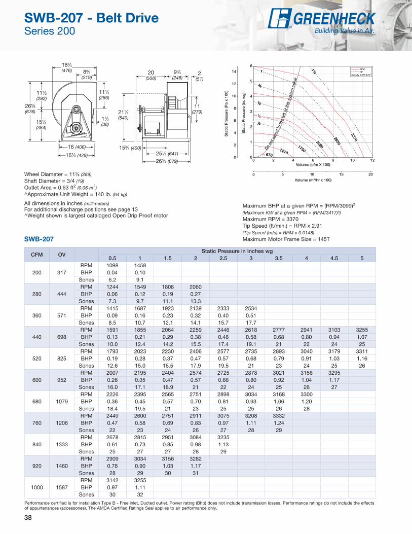
38
CFM OVStatic Pressure in Inches wg
0.5 1 1.5 2 2.5 3 3.5 4 4.5 5
200 317RPM 1098 1458BHP 0.04 0.10
Sones 6.2 9.1
280 444RPM 1244 1549 1808 2060BHP 0.06 0.12 0.19 0.27
Sones 7.3 9.7 11.1 13.3
360 571RPM 1415 1687 1923 2139 2333 2534BHP 0.09 0.16 0.23 0.32 0.40 0.51
Sones 8.5 10.7 12.1 14.1 15.7 17.7
440 698RPM 1591 1855 2064 2259 2446 2618 2777 2941 3103 3255BHP 0.13 0.21 0.29 0.38 0.48 0.58 0.68 0.80 0.94 1.07
Sones 10.0 12.4 14.2 15.5 17.4 19.1 21 22 24 25
520 825RPM 1793 2023 2230 2406 2577 2735 2893 3040 3179 3311BHP 0.19 0.28 0.37 0.47 0.57 0.68 0.79 0.91 1.03 1.16
Sones 12.6 15.0 16.5 17.9 19.5 21 23 24 25 26
600 952RPM 2007 2195 2404 2574 2725 2878 3021 3158 3295BHP 0.26 0.35 0.47 0.57 0.68 0.80 0.92 1.04 1.17
Sones 16.0 17.1 18.9 21 22 24 25 26 27
680 1079RPM 2226 2395 2565 2751 2898 3034 3168 3300BHP 0.36 0.45 0.57 0.70 0.81 0.93 1.06 1.20
Sones 18.4 19.5 21 23 25 25 26 28
760 1206RPM 2449 2600 2751 2911 3075 3208 3332BHP 0.47 0.58 0.69 0.83 0.97 1.11 1.24
Sones 22 23 24 26 27 28 29
840 1333RPM 2678 2815 2951 3084 3235BHP 0.61 0.73 0.85 0.98 1.13
Sones 25 27 27 28 29
920 1460RPM 2909 3034 3156 3282BHP 0.78 0.90 1.03 1.17
Sones 28 29 30 31
1000 1587RPM 3142 3255BHP 0.97 1.11
Sones 30 32
Performance certified is for installation Type B - Free inlet, Ducted outlet. Power rating (Bhp) does not include transmission losses. Performance ratings do not include the effects of appurtenances (accessories). The AMCA Certified Ratings Seal applies to air performance only.
Wheel Diameter = 113⁄8 (289)Shaft Diameter = 3/4 (19)Outlet Area = 0.63 ft2 (0.06 m2)^Approximate Unit Weight = 140 lb. (64 kg)
All dimensions in inches (millimeters)For additional discharge positions see page 13^Weight shown is largest cataloged Open Drip Proof motor
265⁄8 (676)
167⁄8 (429)
11⁄2 (38)
111⁄2 (292)
151⁄8
(384)
111⁄4 (286)
183⁄4 (476)
16 (406)
85⁄8
(219)
Sta
tic P
ress
ure
(in. w
g)
Volume (cfm X 100)
Volume (m3/hr x 100)
Sta
tic P
ress
ure
(Pa
x 10
0)
Do no
t sel
ect t
o th
e le
ft o
f thi
s sy
stem
cur
ve
0 5 10 15 20
0
2
4
6
8
10
12
14
0 2 4 6 8 10 120
1
2
3
4
5
6
670 670
1210 1210
1750
1750
2290
2290
2830 2830
3370 3370
1½ 1½ 1 1
¾ ¾
½ ½
¼ ¼
RPM HP
Density 0.075 lb/ft3
3
Maximum BHP at a given RPM = (RPM/3099)3
(Maximum KW at a given RPM = (RPM/3417)3)Maximum RPM = 3370Tip Speed (ft/min.) = RPM x 2.91(Tip Speed (m/s) = RPM x 0.0148)Maximum Motor Frame Size = 145TSWB-207
153⁄4 (400)
211⁄4 (540)
251⁄4 (641)
263⁄4 (679)
20 (508)
93⁄4 (248)
11 (279)
2 (51)
SWB-207 - Belt Drive Series 200

39
CFM OVStatic Pressure in Inches wg
0.5 0.75 1 1.5 2 2.5 3 3.5 4 4.5
250 397RPM 1125 1343BHP 0.04 0.06
Sones 7.0 8.0
370 587RPM 1270 1451 1610 1909 2172BHP 0.06 0.09 0.11 0.18 0.26
Sones 7.7 8.3 8.8 10.9 13.2
490 778RPM 1445 1606 1753 2014 2240 2472 2681 2874BHP 0.09 0.12 0.16 0.23 0.30 0.39 0.49 0.59
Sones 8.6 9.1 9.7 11.4 13.1 15.3 17.6 19.9
610 968RPM 1640 1785 1918 2160 2378 2575 2755 2941 3121 3289BHP 0.12 0.16 0.21 0.29 0.38 0.47 0.56 0.67 0.79 0.91
Sones 9.2 10.5 11.3 12.5 14.4 16.2 18.1 21 22 23
730 1159RPM 1852 1980 2101 2323 2528 2715 2892 3056 3210 3357BHP 0.18 0.22 0.27 0.37 0.47 0.57 0.68 0.79 0.90 1.01
Sones 11.2 12.4 12.9 13.8 14.8 17.8 19.9 22 22 23
850 1349RPM 2076 2189 2298 2505 2693 2871 3039 3196 3348BHP 0.24 0.29 0.34 0.45 0.57 0.69 0.81 0.93 1.06
Sones 13.5 14.1 14.6 15.6 16.5 17.6 18.6 22 23
970 1540RPM 2310 2409 2507 2697 2874 3041 3198 3350BHP 0.33 0.38 0.44 0.56 0.69 0.82 0.95 1.09
Sones 15.3 16.0 16.6 17.7 18.6 19.5 20 21
1090 1730RPM 2548 2637 2725 2896 3065 3222BHP 0.44 0.50 0.56 0.69 0.82 0.97
Sones 17.5 18.1 18.8 20 21 21
1210 1921RPM 2790 2872 2951 3110 3263BHP 0.57 0.63 0.70 0.84 0.98
Sones 19.9 21 21 22 23
1330 2111RPM 3035 3111 3184 3329BHP 0.73 0.80 0.87 1.02
Sones 22 23 24 25
1450 2302RPM 3282 3352BHP 0.91 0.99
Sones 26 25
Performance certified is for installation Type B - Free inlet, Ducted outlet. Power rating (Bhp) does not include transmission losses. Performance ratings do not include the effects of appurtenances (accessories). The AMCA Certified Ratings Seal applies to air performance only.
Wheel Diameter = 113⁄8 (289)Shaft Diameter = 3/4 (19)Outlet Area = 0.63 ft2 (0.06 m2)^Approximate Unit Weight = 140 lb. (64 kg)
All dimensions in inches (millimeters)For additional discharge positions see page 13^Weight shown is largest cataloged Open Drip Proof motor
265⁄8
(676)
167⁄8 (429)
11⁄2 (38)
111⁄2
(292)
151⁄8 (384)
111⁄4 (286)
183⁄4 (476)
16 (406)
85⁄8 (219)
Sta
tic P
ress
ure
(in. w
g)
Volume (cfm X 100)
Volume (m3/hr x 100)
Sta
tic P
ress
ure
(Pa
x 10
0)
0 5 10 15 20 25
0
2
4
6
8
10
12
14
Do no
t sel
ect t
o th
e le
ft o
f thi
s sy
stem
cur
ve
0 2 4 6 8 10 12 14 160
1
2
3
4
5
6
670 670
1210 1210
1750 1750
2290
2290
2830
2830
3370
3370
1½ 1½
¾ ¾
½ ½
¼ ¼
RPM HP
Density 0.075 lb/ft3
3
Maximum BHP at a given RPM = (RPM/3242)3
(Maximum KW at a given RPM = (RPM/3574)3)Maximum RPM = 3370Tip Speed (ft/min.) = RPM x 2.91(Tip Speed (m/s) = RPM x 0.0148)Maximum Motor Frame Size = 145TSWB-208
153⁄4 (400)
211⁄4 (540)
251⁄4 (641)
263⁄4 (679)
20 (508)
93⁄4 (248)
11 (279)
2 (51)
SWB-208 - Belt Drive Series 200

40
CFM OVStatic Pressure in Inches wg
0.5 1 1.5 2 2.5 3 3.5 4 4.5 5
625 992RPM 1158 1501 1809BHP 0.08 0.17 0.27
Sones 6.3 7.6 9.4
800 1270RPM 1311 1583 1846 2106 2334BHP 0.12 0.21 0.31 0.44 0.58
Sones 7.4 8.2 9.8 11.9 13.9
975 1548RPM 1480 1714 1936 2143 2371 2578 2768BHP 0.17 0.27 0.38 0.50 0.65 0.81 0.97
Sones 8.6 9.5 10.7 12.4 14.3 15.4 16.6
1150 1825RPM 1661 1872 2063 2250 2431 2615 2805 2982 3148 3305BHP 0.24 0.35 0.47 0.60 0.74 0.90 1.07 1.26 1.45 1.65
Sones 10.0 11.0 12.3 13.9 14.8 15.8 17.1 18.3 19.5 21
1325 2103RPM 1853 2041 2214 2379 2541 2704 2854 3019 3185 3342BHP 0.32 0.45 0.58 0.72 0.87 1.03 1.19 1.38 1.58 1.79
Sones 11.9 12.9 14.3 15.2 15.9 16.7 17.6 18.8 20 21
1500 2381RPM 2054 2214 2381 2528 2676 2815 2964 3103 3235BHP 0.43 0.57 0.72 0.87 1.03 1.20 1.37 1.55 1.73
Sones 14.0 15.1 16.0 16.6 17.3 18.1 18.8 19.6 21
1675 2659RPM 2258 2402 2550 2694 2825 2958 3082 3214 3344BHP 0.56 0.71 0.88 1.05 1.21 1.39 1.58 1.77 1.96
Sones 16.5 17.0 17.6 18.3 19.0 19.7 20 21 22
1850 2937RPM 2465 2594 2724 2863 2990 3108 3229 3345BHP 0.72 0.89 1.06 1.25 1.43 1.61 1.81 2.01
Sones 18.3 18.7 19.3 20 21 21 22 23
2025 3214RPM 2674 2793 2913 3034 3159 3274BHP 0.91 1.09 1.28 1.47 1.68 1.88
Sones 20 21 21 22 23 23
2200 3492RPM 2885 2996 3104 3214 3329BHP 1.13 1.33 1.53 1.73 1.95
Sones 22 23 24 24 25
2375 3770RPM 3096 3201 3300BHP 1.39 1.60 1.82
Sones 25 25 26
Performance certified is for installation Type B - Free inlet, Ducted outlet. Power rating (Bhp) does not include transmission losses. Performance ratings do not include the effects of appurtenances (accessories). The AMCA Certified Ratings Seal applies to air performance only.
Wheel Diameter = 113⁄8 (289)Shaft Diameter = 3/4 (19)Outlet Area = 0.63 ft2 (0.06 m2)^Approximate Unit Weight = 140 lb. (64 kg)
All dimensions in inches (millimeters)For additional discharge positions see page 13^Weight shown is largest cataloged Open Drip Proof motor
265⁄8
(676)
167⁄8 (429)
11⁄2 (38)
111⁄2
(292)
151⁄8
(384)
111⁄4
(286)
183⁄4 (476)
16 (406)
85⁄8 (219)
Sta
tic P
ress
ure
(in. w
g)
Volume (cfm X 100)
Volume (m3/hr x 100)
Sta
tic P
ress
ure
(Pa
x 10
0)
0 10 20 30 40
0
2
4
6
8
10
12
14
0 3 6 9 12 15 18 21 24 270
1
2
3
4
5
6
700 700
1235 1235
1770
1770
2305
2305
2840 2840
3370 3370
2 2 1½ 1½
1 1 ¾ ¾
½ ½
¼ ¼3
RPM HP
Density 0.075 lb/ft3
Do no
t sel
ect t
o th
e le
ft of
this
sys
tem
cur
ve
Maximum BHP at a given RPM = (RPM/2649)3
(Maximum KW at a given RPM = (RPM/2921)3)Maximum RPM = 3370Tip Speed (ft/min.) = RPM x 2.91(Tip Speed (m/s) = RPM x 0.0148)Maximum Motor Frame Size = 145TSWB-210
153⁄4 (400)
211⁄4 (540)
251⁄4 (641)
263⁄4 (679)
20 (508)
93⁄4 (248)
11 (279)
2 (51)
SWB-210 - Belt Drive Series 200

41
CFM OVStatic Pressure in Inches wg
0.5 1 1.5 2 2.5 3 3.5 4 4.5 5
600 706RPM 1022 1372BHP 0.08 0.16
Sones 6.0 7.9
850 1000RPM 1150 1447 1710 1941BHP 0.11 0.21 0.33 0.45
Sones 7.2 8.5 10.4 12.7
1100 1294RPM 1325 1561 1799 2005 2208 2392 2562 2719BHP 0.17 0.28 0.42 0.56 0.71 0.87 1.03 1.20
Sones 8.7 9.8 11.4 13.6 15.2 16.5 17.8 19.0
1350 1588RPM 1522 1728 1913 2113 2291 2457 2625 2783 2931 3071BHP 0.25 0.38 0.52 0.68 0.85 1.03 1.21 1.40 1.59 1.79
Sones 10.5 11.7 13.2 14.9 16.0 17.2 18.5 19.8 21 23
1600 1882RPM 1732 1905 2080 2233 2404 2564 2712 2851 2995 3135BHP 0.36 0.51 0.67 0.84 1.02 1.21 1.41 1.62 1.83 2.05
Sones 12.8 14.0 15.7 16.5 17.4 18.4 19.5 21 22 23
1850 2176RPM 1947 2104 2255 2403 2538 2679 2825 2962 3091BHP 0.50 0.66 0.84 1.03 1.22 1.43 1.65 1.87 2.10
Sones 15.6 16.8 17.6 18.4 19.2 20 21 22 23
2100 2471RPM 2177 2312 2443 2578 2708 2830 2944 3076BHP 0.69 0.86 1.05 1.26 1.47 1.69 1.91 2.16
Sones 18.4 19.0 19.7 21 21 22 23 24
2350 2765RPM 2409 2524 2646 2761 2883 3001 3112BHP 0.92 1.10 1.31 1.53 1.76 2.00 2.24
Sones 21 21 22 23 24 25 26
2600 3059RPM 2641 2739 2855 2962 3065BHP 1.20 1.39 1.62 1.85 2.10
Sones 23 24 25 26 27
2850 3353RPM 2874 2968 3067 3169BHP 1.53 1.75 1.98 2.23
Sones 27 27 28 29
3100 3647RPM 3108 3199BHP 1.91 2.17
Sones 30 31
Performance certified is for installation Type B - Free inlet, Ducted outlet. Power rating (Bhp) does not include transmission losses. Performance ratings do not include the effects of appurtenances (accessories). The AMCA Certified Ratings Seal applies to air performance only.
283⁄8 (721)
12 (305)
167⁄8 (429)
11⁄2 (38)
131⁄4 (337)
151⁄8 (384)
13 (330)
213⁄8 (543)
221⁄4 (565)
16 (406)213⁄8 (543)
229⁄10 (582)
151⁄2
(394)95⁄8
(244)
13 (330)
93⁄4 (248)
2 (51)
Wheel Diameter = 121⁄2 (318)Shaft Diameter = 1 (25)Outlet Area = 0.85 ft2 (0.08 m2)^Approximate Unit Weight = 170 lb. (77 kg)
All dimensions in inches (millimeters)For additional discharge positions see page 13^Weight shown is largest cataloged Open Drip Proof motor
Sta
tic P
ress
ure
(in. w
g)
Volume (cfm X 100)
Volume (m3/hr x 100)
Sta
tic P
ress
ure
(Pa
x 10
0)
Do no
t sel
ect t
o th
e le
ft o
f thi
s sy
stem
cur
ve
0 10 20 30 40 50
0
2
4
6
8
10
12
14
0 5 10 15 20 25 30 350
1
2
3
4
5
6
700 700
1210 1210
1725
1725
2240
2240
2755 2755
3262 3262
2 2 1½ 1½
1 1 ¾ ¾
½ ½
¼ ¼
RPM HP
Density 0.075 lb/ft3
3
Maximum BHP at a given RPM = (RPM/2372)3
(Maximum KW at a given RPM = (RPM/2615)3)
Maximum RPM = 3262Tip Speed (ft/min.) = RPM x 3.21(Tip Speed (m/s) = RPM x 0.0163)Maximum Motor Frame Size = 145TSWB-212
SWB-212 - Belt Drive Series 200

42
CFM OVStatic Pressure in Inches wg
0.5 0.75 1 1.5 2 2.5 3 3.5 4 4.5
1000 971RPM 998 1144 1287BHP 0.12 0.18 0.24
Sones 6.9 7.5 8.4
1280 1243RPM 1134 1248 1358 1585BHP 0.18 0.24 0.31 0.46
Sones 8.2 8.7 9.2 11.0
1560 1515RPM 1290 1384 1478 1660 1850 2034BHP 0.26 0.33 0.40 0.56 0.74 0.95
Sones 9.6 10.2 10.8 12.2 14.2 15.8
1840 1786RPM 1457 1540 1619 1778 1931 2093 2249BHP 0.37 0.45 0.53 0.70 0.89 1.10 1.32
Sones 11.5 12.0 12.6 14.1 15.5 16.5 17.7
2120 2058RPM 1629 1703 1775 1913 2051 2181 2318 2462 2596 2730BHP 0.51 0.59 0.69 0.87 1.08 1.29 1.52 1.77 2.03 2.31
Sones 13.7 14.2 15.0 16.3 17.1 17.9 18.8 19.8 21 23
2400 2330RPM 1807 1874 1938 2063 2184 2307 2423 2543 2665 2790BHP 0.68 0.78 0.88 1.09 1.30 1.53 1.78 2.03 2.29 2.58
Sones 16.4 17.0 17.3 18.1 18.8 19.7 20 21 22 24
2680 2602RPM 1987 2048 2107 2222 2332 2440 2550 2656 2758 2869BHP 0.89 1.01 1.12 1.34 1.58 1.81 2.07 2.34 2.62 2.90
Sones 18.8 19.0 19.3 20 21 22 22 23 24 25
2960 2874RPM 2170 2226 2280 2386 2489 2587 2685 2784 2884BHP 1.14 1.27 1.40 1.64 1.89 2.16 2.42 2.69 2.99
Sones 21 21 21 22 23 24 25 26 27
3240 3146RPM 2355 2407 2457 2555 2650 2744 2832BHP 1.44 1.58 1.72 1.99 2.26 2.54 2.83
Sones 23 23 24 25 25 26 27
3520 3417RPM 2541 2589 2636 2727 2816BHP 1.79 1.94 2.10 2.40 2.68
Sones 26 26 27 27 28
3800 3689RPM 2729 2773 2817BHP 2.19 2.36 2.53
Sones 29 30 30
Performance certified is for installation Type B - Free inlet, Ducted outlet. Power rating (Bhp) does not include transmission losses. Performance ratings do not include the effects of appurtenances (accessories). The AMCA Certified Ratings Seal applies to air performance only.
311⁄4 (794)
13 (330)
187⁄8 (479)
11⁄2 (38)
145⁄8 (371)
165⁄8 (422)
141⁄4 (362)
233⁄8 (594)
243⁄4 (629)
175⁄8 (448)271⁄2 (699)
301⁄8 (765)
213⁄4
(552)105⁄8 (270)
14 (356)
105⁄8 (270)
2 (51)
Wheel Diameter = 133⁄4 (349)Shaft Diameter = 1 (25)Outlet Area = 1.03 ft2 (0.10 m2)^Approximate Unit Weight = 183 lb. (83 kg)
All dimensions in inches (millimeters)For additional discharge positions see page 13^Weight shown is largest cataloged Open Drip Proof motor
Sta
tic P
ress
ure
(in. w
g)
Volume (cfm X 100)
Volume (m3/hr x 100)
Sta
tic P
ress
ure
(Pa
x 10
0)
Do not
sel
ect t
o th
e le
ft of
this
sys
tem
cur
ve
0 20 40 60
0
2
4
6
8
10
12
14
0 5 10 15 20 25 30 35 40 450
1
2
3
4
5
6
700 700
1140
1140
1580
1580
2020 2020
2460 2460
2902 2902
3 3 2 2 1½ 1½
1 1
¾ ¾ ½ ½
¼ ¼
RPM HP
Density 0.075 lb/ft3
3
Maximum BHP at a given RPM = (RPM/2002)3
(Maximum KW at a given RPM = (RPM/2207)3)Maximum RPM = 2902Tip Speed (ft/min.) = RPM x 3.53(Tip Speed (m/s) = RPM x 0.0179)Maximum Motor Frame Size = 184TSWB-213
SWB-213 - Belt Drive Series 200

43
CFM OVStatic Pressure in Inches wg
0.5 0.75 1 1.5 2 2.5 3 3.5 4 4.5
1200 960RPM 886 1024 1157BHP 0.15 0.21 0.29
Sones 6.9 7.5 8.5
1550 1240RPM 1009 1112 1214 1421BHP 0.22 0.29 0.37 0.56
Sones 8.2 8.7 9.3 11.2
1900 1520RPM 1150 1236 1322 1487 1661 1830BHP 0.32 0.40 0.49 0.68 0.91 1.16
Sones 9.7 10.2 10.8 12.3 14.4 15.9
2250 1800RPM 1301 1377 1449 1593 1732 1879 2020 2165BHP 0.45 0.54 0.64 0.85 1.09 1.34 1.61 1.92
Sones 11.5 12.1 12.7 14.2 15.6 16.6 17.9 19.3
2600 2080RPM 1458 1525 1591 1715 1840 1958 2083 2213 2333 2456BHP 0.62 0.72 0.84 1.07 1.32 1.58 1.86 2.17 2.48 2.83
Sones 13.8 14.3 15.0 16.3 17.2 18.0 19.0 20 21 23
2950 2360RPM 1620 1680 1738 1852 1961 2072 2176 2285 2396BHP 0.83 0.96 1.08 1.33 1.59 1.88 2.18 2.49 2.81
Sones 16.5 17.0 17.4 18.2 19.0 19.8 21 22 23
3300 2640RPM 1785 1839 1893 1996 2095 2193 2293 2388BHP 1.09 1.23 1.37 1.65 1.94 2.23 2.54 2.88
Sones 19.0 19.2 19.4 20 21 22 23 24
3650 2920RPM 1951 2001 2050 2145 2238 2326 2416BHP 1.41 1.56 1.72 2.02 2.33 2.66 2.98
Sones 21 21 22 22 23 24 25
4000 3200RPM 2120 2166 2211 2299 2385BHP 1.78 1.95 2.13 2.46 2.79
Sones 24 24 24 25 26
4350 3480RPM 2290 2332 2374 2456BHP 2.21 2.41 2.60 2.97
Sones 26 27 27 28
4700 3760RPM 2460 2500BHP 2.72 2.93
Sones 30 30
Performance certified is for installation Type B - Free inlet, Ducted outlet. Power rating (Bhp) does not include transmission losses. Performance ratings do not include the effects of appurtenances (accessories). The AMCA Certified Ratings Seal applies to air performance only.
343⁄4 (883)
15 (381)
211⁄8 (537)
11⁄2 (38)
161⁄4 (413)
181⁄2
(470)
153⁄4 (400)
253⁄4 (654)
271⁄2 (699)
20 (508)271⁄8 (689)
311⁄4 (794)
211⁄2 (546)
115⁄8 (295)
157⁄8 (403)
115⁄8 (296)
2 (51)
Wheel Diameter = 151⁄4 (387)Shaft Diameter = 1 (25)Outlet Area = 1.25 ft2 (0.12 m2)^Approximate Unit Weight = 231 lb. (105 kg)
All dimensions in inches (millimeters)For additional discharge positions see page 13^Weight shown is largest cataloged Open Drip Proof motor
Sta
tic P
ress
ure
(in. w
g)
Volume (cfm X 100)
Volume (m3/hr x 100)
Sta
tic P
ress
ure
(Pa
x 10
0)
0 20 40 60 80
0
2
4
6
8
10
12
14
0 9 18 27 36 45 540
1
2
3
4
5
6
600 600
1000
1000
1400
1400
1800 1800
2200 2200
2604 2604
3 3 2 2 1½ 1½
1 1 ¾ ¾
½ ½
¼ ¼
3
RPM HP
Density 0.075 lb/ft3
Do no
t sel
ect t
o th
e le
ft of
this
sys
tem
cur
ve
Maximum BHP at a given RPM = (RPM/1679)3
(Maximum KW at a given RPM = (RPM/1851)3)Maximum RPM = 2604Tip Speed (ft/min.) = RPM x 3.93(Tip Speed (m/s) = RPM x 0.0200)Maximum Motor Frame Size = 184TSWB-215
SWB-215 - Belt Drive Series 200

44
CFM OVStatic Pressure in Inches wg
0.5 0.75 1 1.5 2 2.5 3 3.5 4 4.5
1200 789RPM 762 900BHP 0.15 0.22
Sones 5.9 6.9
1650 1086RPM 848 959 1072 1267BHP 0.22 0.31 0.40 0.61
Sones 7.1 7.6 8.4 10.4
2100 1382RPM 970 1059 1147 1322 1487 1632BHP 0.32 0.42 0.53 0.77 1.03 1.30
Sones 8.5 9.0 9.6 11.1 13.3 14.8
2550 1678RPM 1109 1182 1255 1400 1543 1687 1818 1939BHP 0.46 0.58 0.70 0.96 1.25 1.56 1.88 2.21
Sones 10.1 10.6 11.2 12.7 14.4 15.6 16.8 18.1
3000 1974RPM 1256 1320 1381 1505 1629 1749 1874 1994 2106 2211BHP 0.65 0.79 0.92 1.20 1.52 1.85 2.20 2.57 2.94 3.33
Sones 12.2 12.7 13.3 14.7 15.7 16.6 17.6 18.9 20 21
3450 2270RPM 1410 1462 1520 1626 1734 1841 1949 2050 2162 2267BHP 0.90 1.04 1.20 1.51 1.84 2.20 2.57 2.96 3.38 3.80
Sones 14.6 15.1 15.7 16.6 17.4 18.3 19.2 20 21 22
3900 2566RPM 1566 1616 1661 1758 1853 1950 2042 2141 2234 2324BHP 1.21 1.37 1.53 1.89 2.24 2.61 3.01 3.43 3.86 4.30
Sones 17.5 17.6 17.9 18.5 19.3 20 21 22 23 24
4350 2862RPM 1724 1770 1813 1900 1985 2069 2156 2239 2326BHP 1.59 1.78 1.95 2.34 2.73 3.11 3.53 3.97 4.43
Sones 19.7 19.9 20 21 21 22 23 24 25
4800 3158RPM 1884 1926 1967 2042 2124 2200 2277 2355BHP 2.05 2.25 2.45 2.85 3.29 3.72 4.14 4.60
Sones 22 22 23 23 24 25 26 27
5250 3454RPM 2046 2084 2123 2194 2265 2338BHP 2.60 2.81 3.04 3.46 3.92 4.41
Sones 25 25 25 26 27 28
5700 3750RPM 2208 2244 2279 2348BHP 3.25 3.47 3.71 4.19
Sones 28 29 29 30
Performance certified is for installation Type B - Free inlet, Ducted outlet. Power rating (Bhp) does not include transmission losses. Performance ratings do not include the effects of appurtenances (accessories). The AMCA Certified Ratings Seal applies to air performance only.
381⁄8 (968)
16 (406)
227⁄8 (581)
11⁄2 (38)
173⁄4 (451)
203⁄8 (518)
171⁄2 (445)
28 (711)
30 (762)
213⁄8 (543)301⁄4 (769)
323⁄8 (823)
211⁄2 (546)
123⁄4 (324)
171⁄2 (445)
121⁄2 (318)
2 (51)
Wheel Diameter = 163⁄4 (425)Shaft Diameter = 11⁄4 (32)Outlet Area = 1.52 ft2 (0.14 m2)^Approximate Unit Weight = 251 lb. (114 kg)
All dimensions in inches (millimeters)For additional discharge positions see page 13^Weight shown is largest cataloged Open Drip Proof motor
Sta
tic P
ress
ure
(in. w
g)
Volume (cfm X 1000)
Volume (m3/hr x 1000)
Sta
tic P
ress
ure
(Pa
x 10
0)
Do no
t sel
ect t
o th
e le
ft o
f thi
s sy
stem
cur
ve
0 2 4 6 8 10
0
2
4
6
8
10
12
14
0 1 2 3 4 5 6 70
1
2
3
4
5
6
600 600
955 955
1310
1310
1665 1665
2020 2020
2378 2378
5 5 3 3 2 2
1½ 1½
1 1 ¾ ¾
½ ½
¼ ¼
RPM HP
Density 0.075 lb/ft3
3
Maximum BHP at a given RPM = (RPM/1414)3
(Maximum KW at a given RPM = (RPM/1559)3)Maximum RPM = 2378Tip Speed (ft/min.) = RPM x 4.32(Tip Speed (m/s) = RPM x 0.0219)Maximum Motor Frame Size = 184TSWB-216
SWB-216 - Belt Drive Series 200

45
CFM OVStatic Pressure in Inches wg
0.5 1 1.5 2 2.5 3 3.5 4 4.5 5
2000 1070RPM 762 963 1136BHP 0.26 0.49 0.75
Sones 10.1 11.3 13.4
2500 1337RPM 862 1023 1185 1330 1459BHP 0.37 0.62 0.92 1.24 1.58
Sones 10.1 11.6 13.0 15.2 17.9
3000 1604RPM 974 1110 1245 1380 1507 1623 1730BHP 0.52 0.80 1.12 1.47 1.85 2.24 2.65
Sones 11.5 12.6 13.9 15.5 18.3 21 24
3500 1872RPM 1092 1211 1327 1443 1557 1672 1779 1878 1971 2060BHP 0.72 1.03 1.36 1.74 2.15 2.58 3.02 3.48 3.95 4.43
Sones 13.6 14.2 15.2 16.8 19.1 22 25 27 29 31
4000 2139RPM 1218 1322 1423 1525 1626 1727 1828 1927 2020 2108BHP 0.97 1.32 1.68 2.07 2.51 2.95 3.43 3.93 4.44 4.96
Sones 15.7 16.4 17.3 18.7 21 23 25 27 29 32
4500 2406RPM 1346 1438 1530 1619 1709 1800 1890 1979 2069BHP 1.28 1.66 2.07 2.48 2.92 3.41 3.90 4.42 4.96
Sones 18.2 18.8 19.6 21 23 24 26 28 30
5000 2764RPM 1475 1557 1643 1723 1804 1885 1967 2048BHP 1.66 2.08 2.52 2.97 3.43 3.91 4.45 5.00
Sones 21 21 22 24 25 26 28 29
5500 2941RPM 1605 1683 1758 1834 1907 1981 2055BHP 2.10 2.58 3.04 3.54 4.03 4.54 5.07
Sones 24 24 25 26 27 28 30
6000 3209RPM 1737 1810 1877 1949 2017 2084BHP 2.63 3.15 3.65 4.18 4.72 5.25
Sones 27 28 28 29 30 31
6500 3476RPM 1869 1938 2002 2065 2131BHP 3.26 3.81 4.37 4.91 5.49
Sones 31 31 31 32 33
7000 3743RPM 2003 2067 2128BHP 3.98 4.57 5.18
Sones 34 35 35
Performance certified is for installation Type B - Free inlet, Ducted outlet. Power rating (Bhp) does not include transmission losses. Performance ratings do not include the effects of appurtenances (accessories). The AMCA Certified Ratings Seal applies to air performance only.
42 (1067)
177⁄8 (454)
25 (635)
11⁄2 (38)
195⁄8 (498)
223⁄8 (568)
193⁄8 (492)
307⁄8 (784)
331⁄4 (845)
233⁄8 (594)321⁄4 (819)
34 (864)
22 (559)
141⁄8 (359)
191⁄4 (489)
133⁄4 (349)
2 (51)
Wheel Diameter = 185⁄8 (473)Shaft Diameter = 11⁄4 (32)Outlet Area = 1.87 ft2 (0.17 m2)^Approximate Unit Weight = 324 lb. (147 kg)
All dimensions in inches (millimeters)For additional discharge positions see page 13^Weight shown is largest cataloged Open Drip Proof motor
Sta
tic P
ress
ure
(in. w
g)
Volume (cfm X 1000)
Volume (m3/hr x 1000)
Sta
tic P
ress
ure
(Pa
x 10
0)
Do no
t sel
ect t
o th
e le
ft of
this
sys
tem
cur
ve
0 2 4 6 8 10 12
0
2
4
6
8
10
12
14
0 1 2 3 4 5 6 7 80
1
2
3
4
5
6
555 555
870 870
1190
1190
1510 1510
1830 1830
2147 2147
5 5
3 3
2 2 1½ 1½
1 1
¾ ¾
½ ½
¼ ¼
RPM HP
Density 0.075 lb/ft3
3
Maximum BHP at a given RPM = (RPM/1196)3(Maximum KW at a given RPM = (RPM/1319)3)Maximum RPM = 2147Tip Speed (ft/min.) = RPM x 4.78(Tip Speed (m/s) = RPM x 0.0243)Maximum Motor Frame Size = 213TSWB-218
SWB-218 - Belt Drive Series 200

46
CFM OVStatic Pressure in Inches wg
0.5 1 1.5 2 2.5 3 3.5 4 4.5 4.75
2000 897RPM 647 860BHP 0.25 0.51
Sones 8.7 11.5
2650 1188RPM 731 897 1065 1206BHP 0.36 0.65 1.00 1.39
Sones 9.2 11.2 13.4 15.9
3300 1480RPM 836 970 1104 1243 1367 1480BHP 0.53 0.85 1.21 1.64 2.10 2.58
Sones 10.6 12.1 13.5 15.8 19.0 22
3950 1771RPM 951 1064 1177 1289 1405 1517 1621 1717 1807 1851BHP 0.76 1.11 1.51 1.94 2.43 2.96 3.51 4.08 4.67 4.97
Sones 13.0 13.7 14.9 16.4 19.4 23 26 28 30 32
4600 2063RPM 1072 1171 1267 1364 1461 1556 1658 1754 1845 1888BHP 1.06 1.46 1.88 2.35 2.85 3.38 3.98 4.60 5.23 5.55
Sones 15.2 15.8 16.8 18.4 21 23 26 28 31 32
5250 2354RPM 1198 1285 1370 1454 1539 1624 1708 1792 1882 1925BHP 1.44 1.88 2.35 2.84 3.37 3.94 4.52 5.15 5.83 6.18
Sones 17.8 18.4 19.4 21 23 25 26 28 31 32
5900 2646RPM 1325 1401 1481 1555 1630 1706 1781 1857 1932BHP 1.90 2.40 2.92 3.45 4.00 4.58 5.23 5.87 6.52
Sones 21 21 22 24 25 26 28 30 32
6550 2937RPM 1453 1525 1594 1664 1731 1799 1867 1935BHP 2.47 3.04 3.59 4.18 4.76 5.37 6.01 6.70
Sones 24 25 25 26 27 29 30 32
7200 3229RPM 1583 1650 1711 1777 1840 1900BHP 3.15 3.78 4.37 5.01 5.66 6.30
Sones 28 28 28 29 30 32
7850 3520RPM 1714 1776 1835 1892 1952BHP 3.97 4.64 5.32 5.96 6.67
Sones 31 32 32 33 34
8500 3812RPM 1846 1904 1960BHP 4.92 5.63 6.38
Sones 36 36 37
Performance certified is for installation Type B - Free inlet, Ducted outlet. Power rating (Bhp) does not include transmission losses. Performance ratings do not include the effects of appurtenances (accessories). The AMCA Certified Ratings Seal applies to air performance only.
46(1168)
193⁄8 (492)
273⁄8 (695)
11⁄2 (38)
211⁄2 (546)
241⁄2 (622)
211⁄8 (537)
335⁄8
(854)
361⁄8 (918)
255⁄8 (651)35 (889)
37 (940)
233⁄4 (603)
153⁄8 (390)
211⁄8 (537)
147⁄8
(378)2
(51)
Wheel Diameter = 203⁄8 (518)Shaft Diameter = 11⁄4 (32)Outlet Area = 2.23 ft2 (0.21 m2)^Approximate Unit Weight = 389 lb. (176 kg)
All dimensions in inches (millimeters)For additional discharge positions see page 13^Weight shown is largest cataloged Open Drip Proof motor
Sta
tic P
ress
ure
(in. w
g)
Volume (cfm X 1000)
Volume (m3/hr x 1000)
Sta
tic P
ress
ure
(Pa
x 10
0)
Do no
t sel
ect t
o th
e le
ft o
f thi
s sy
stem
cur
ve
0 2 4 6 8 10 12 14 16
0
2
4
6
8
10
12
14
0 2 4 6 8 100
1
2
3
4
5
6
507 507
795 795
1085
1085
1375 1375
1665 1665
1961 1961
7½ 7½ 5 5 3 3
2 2
1½ 1½
1 1
¾ ¾
½ ½
¼ ¼
RPM HP
Density 0.075 lb/ft3
3
Maximum BHP at a given RPM = (RPM/1027)3
(Maximum KW at a given RPM = (RPM/1132)3)Maximum RPM = 1961Tip Speed (ft/min.) = RPM x 5.23(Tip Speed (m/s) = RPM x 0.0266)Maximum Motor Frame Size = 215TSWB-220
SWB-220 - Belt Drive Series 200
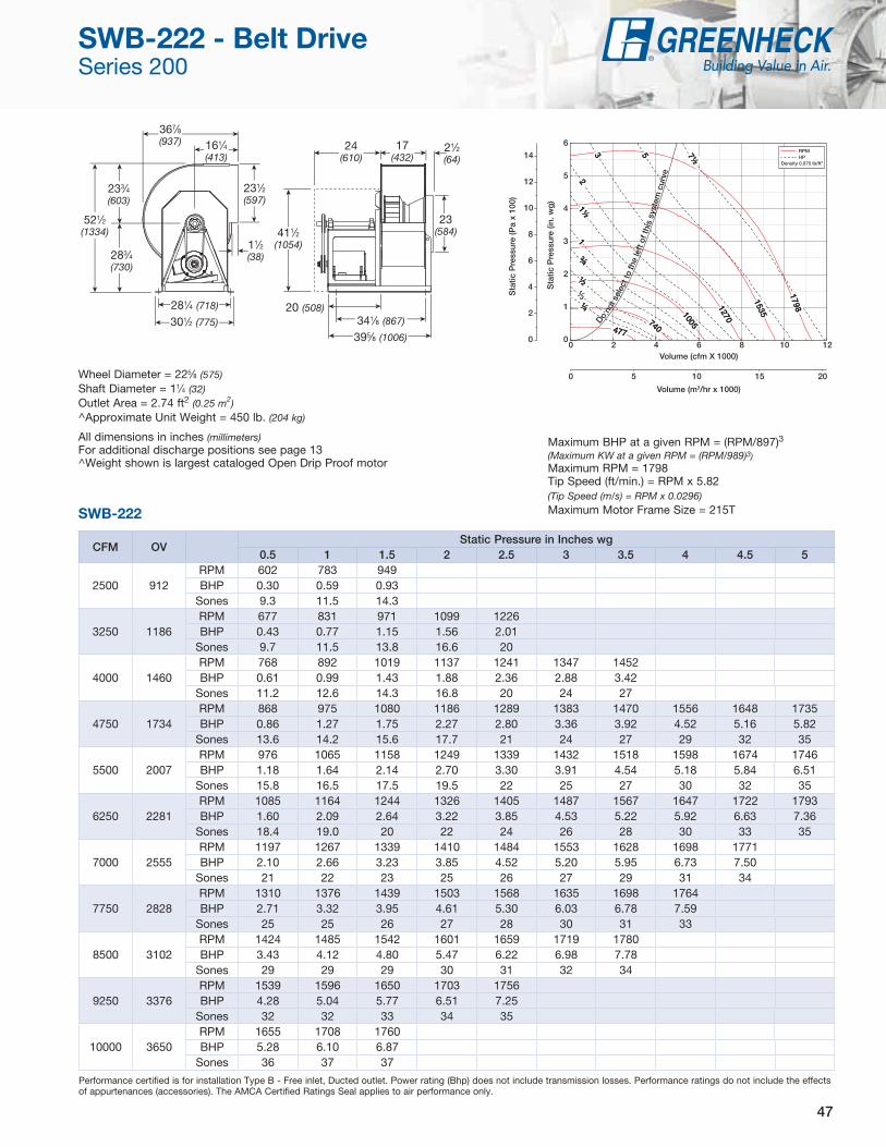
47
CFM OVStatic Pressure in Inches wg
0.5 1 1.5 2 2.5 3 3.5 4 4.5 5
2500 912RPM 602 783 949BHP 0.30 0.59 0.93
Sones 9.3 11.5 14.3
3250 1186RPM 677 831 971 1099 1226BHP 0.43 0.77 1.15 1.56 2.01
Sones 9.7 11.5 13.8 16.6 20
4000 1460RPM 768 892 1019 1137 1241 1347 1452BHP 0.61 0.99 1.43 1.88 2.36 2.88 3.42
Sones 11.2 12.6 14.3 16.8 20 24 27
4750 1734RPM 868 975 1080 1186 1289 1383 1470 1556 1648 1735BHP 0.86 1.27 1.75 2.27 2.80 3.36 3.92 4.52 5.16 5.82
Sones 13.6 14.2 15.6 17.7 21 24 27 29 32 35
5500 2007RPM 976 1065 1158 1249 1339 1432 1518 1598 1674 1746BHP 1.18 1.64 2.14 2.70 3.30 3.91 4.54 5.18 5.84 6.51
Sones 15.8 16.5 17.5 19.5 22 25 27 30 32 35
6250 2281RPM 1085 1164 1244 1326 1405 1487 1567 1647 1722 1793BHP 1.60 2.09 2.64 3.22 3.85 4.53 5.22 5.92 6.63 7.36
Sones 18.4 19.0 20 22 24 26 28 30 33 35
7000 2555RPM 1197 1267 1339 1410 1484 1553 1628 1698 1771BHP 2.10 2.66 3.23 3.85 4.52 5.20 5.95 6.73 7.50
Sones 21 22 23 25 26 27 29 31 34
7750 2828RPM 1310 1376 1439 1503 1568 1635 1698 1764BHP 2.71 3.32 3.95 4.61 5.30 6.03 6.78 7.59
Sones 25 25 26 27 28 30 31 33
8500 3102RPM 1424 1485 1542 1601 1659 1719 1780BHP 3.43 4.12 4.80 5.47 6.22 6.98 7.78
Sones 29 29 29 30 31 32 34
9250 3376RPM 1539 1596 1650 1703 1756BHP 4.28 5.04 5.77 6.51 7.25
Sones 32 32 33 34 35
10000 3650RPM 1655 1708 1760BHP 5.28 6.10 6.87
Sones 36 37 37
Performance certified is for installation Type B - Free inlet, Ducted outlet. Power rating (Bhp) does not include transmission losses. Performance ratings do not include the effects of appurtenances (accessories). The AMCA Certified Ratings Seal applies to air performance only.
521⁄2
(1334)
20 (508)301⁄2 (775)
11⁄2 (38)
233⁄4 (603)
283⁄4 (730)
231⁄2 (597)
367⁄8 (937)
411⁄2 (1054)
281⁄4 (718)
341⁄8 (867)
395⁄8 (1006)
24 (610)
17 (432)
23 (584)
161⁄4
(413)21⁄2 (64)
Wheel Diameter = 225⁄8 (575)Shaft Diameter = 11⁄4 (32)Outlet Area = 2.74 ft2 (0.25 m2)^Approximate Unit Weight = 450 lb. (204 kg)
All dimensions in inches (millimeters)For additional discharge positions see page 13^Weight shown is largest cataloged Open Drip Proof motor
Sta
tic P
ress
ure
(in. w
g)
Volume (cfm X 1000)
Volume (m3/hr x 1000)
Sta
tic P
ress
ure
(Pa
x 10
0)
Do no
t sel
ect t
o th
e le
ft o
f thi
s sy
stem
cur
ve
0 5 10 15 20
0
2
4
6
8
10
12
14
0 2 4 6 8 10 120
1
2
3
4
5
6
477 477
740 740
1005
1005
1270 1270
1535 1535
1798 1798
7½ 7½
5 5 3 3
2 2 1½ 1½
1 1
¾ ¾
½ ½
¼ ¼
RPM HP
Density 0.075 lb/ft3
3
Maximum BHP at a given RPM = (RPM/897)3
(Maximum KW at a given RPM = (RPM/989)3)
Maximum RPM = 1798Tip Speed (ft/min.) = RPM x 5.82(Tip Speed (m/s) = RPM x 0.0296)Maximum Motor Frame Size = 215TSWB-222
SWB-222 - Belt Drive Series 200

48
CFM OVStatic Pressure in Inches wg
0.5 0.75 1 1.5 2 2.5 3 3.5 4 4.5
3000 882RPM 526 614 699BHP 0.34 0.51 0.71
Sones 7.4 9.1 12.7
3900 1147RPM 594 659 726 861BHP 0.50 0.68 0.89 1.37
Sones 8.5 9.4 10.4 14.5
4800 1412RPM 674 729 783 890 1001 1106BHP 0.71 0.92 1.14 1.64 2.20 2.84
Sones 10.0 11.0 11.7 13.2 16.1 18.9
5700 1676RPM 760 809 856 945 1036 1126 1221 1309BHP 1.00 1.24 1.49 2.01 2.60 3.22 3.95 4.72
Sones 12.4 13.0 13.5 14.7 16.5 19.1 22 25
6600 1941RPM 851 894 936 1015 1093 1171 1251 1329 1411 1487BHP 1.36 1.64 1.92 2.49 3.11 3.77 4.49 5.24 6.10 6.98
Sones 14.5 15.2 15.8 17.0 18.2 20 23 25 27 29
7500 2206RPM 946 982 1020 1093 1162 1230 1300 1369 1438 1508BHP 1.82 2.13 2.44 3.09 3.74 4.45 5.19 5.98 6.80 7.65
Sones 17.1 17.8 18.6 19.7 21 22 24 26 27 29
8400 2471RPM 1041 1076 1108 1175 1240 1301 1362 1423 1484BHP 2.38 2.73 3.08 3.79 4.51 5.24 6.03 6.85 7.69
Sones 20 21 22 23 24 25 25 26 28
9300 2735RPM 1139 1170 1200 1261 1320 1378 1433 1489BHP 3.07 3.44 3.83 4.60 5.39 6.20 7.01 7.87
Sones 24 25 25 27 27 27 28 28
10200 3000RPM 1239 1266 1294 1348 1404 1458 1510BHP 3.89 4.29 4.71 5.55 6.41 7.28 8.16
Sones 28 29 29 30 30 30 31
11100 3265RPM 1339 1364 1390 1440 1490BHP 4.85 5.28 5.73 6.65 7.57
Sones 31 32 32 32 33
12000 3529RPM 1440 1463 1486 1534BHP 5.98 6.43 6.90 7.89
Sones 34 35 35 36
Performance certified is for installation Type B - Free inlet, Ducted outlet. Power rating (Bhp) does not include transmission losses. Performance ratings do not include the effects of appurtenances (accessories). The AMCA Certified Ratings Seal applies to air performance only.
573⁄4 (1467)
193⁄4 (502)
335⁄8 (854)
11⁄2 (38)
261⁄4 (667)
311⁄2
(800)
26 (660)
405⁄8 (1032)
453⁄4 (1162)
315⁄8 (803)36 (914)
411⁄2 (1054)
25 (635)
19 (483)
257⁄8 (657)
173⁄4 (451)
21⁄2 (64)
Wheel Diameter = 243⁄4 (629)Shaft Diameter = 11⁄2 (38)Outlet Area = 3.40 ft2 (0.32 m2)^Approximate Unit Weight = 568 lb. (258 kg)
All dimensions in inches (millimeters)For additional discharge positions see page 13^Weight shown is largest cataloged Open Drip Proof motor
Sta
tic P
ress
ure
(in. w
g)
Volume (cfm X 1000)
Volume (m3/hr x 1000)
Sta
tic P
ress
ure
(Pa
x 10
0)
Do no
t sel
ect t
o th
e le
ft of
this
sys
tem
cur
ve
0 5 10 15 20
0
2
4
6
8
10
12
14
0 2 4 6 8 10 12 140
1
2
3
4
5
6
424 424
655 655
890 890
1125 1125
1360 1360
1588 1588
7½ 7½
5 5
3 3 2 2
1½ 1½
1 1
¾ ¾
½ ½
RPM HP
Density 0.075 lb/ft3
3
Maximum BHP at a given RPM = (RPM/749)3
(Maximum KW at a given RPM = (RPM/826)3)Maximum RPM = 1588Tip Speed (ft/min.) = RPM x 6.41(Tip Speed (m/s) = RPM x 0.0326)Maximum Motor Frame Size = 256TSWB-224
SWB-224 - Belt Drive Series 200

49
Model SFD Direct Drive Utility Fans
Supply, exhaust or return air fans shall be of the direct drive utility fan type in AMCA Arrangement 4 with a single-width, single-inlet housing, in clockwise or counterclockwise rotation as specified.
The housing shall be constructed of heavy-gauge galvanized steel with lock formed seams permitting no air leakage. The housing shall be easily rotated in the field to any of the eight standard discharge positions. Housing supports and drive frame shall be constructed of heavy-gauge galvanized steel to minimize vibration and rigidly support the motor and wheel.
The fan wheel shall be of the forward-curved type and shall be constructed of heavy-gauge aluminum. Wheels shall be statically and dynamically balanced. The wheel cone and fan inlet cone shall be carefully matched for maximum performance and operating efficiency. Motors shall be heavy-duty ball bearing type matched to the fan load and furnished at the specified voltage, phase and enclosure.
All fans shall bear the AMCA Air Performance seal.
Utility fans shall be model SFD (with forward-curved wheels) as manufactured by Greenheck Fan Corporation of Schofield, Wisconsin, USA.
Model SFB Belt Drive Utility Fans
Supply, exhaust and return air fans shall be of the belt driven utility fan type in AMCA Arrangement 10 with a single-width, single-inlet housing, in clockwise or counterclockwise rotation as specified.
The housing shall be constructed of heavy-gauge steel with airtight lock formed seams. The housing shall be easily rotated in the field to any of the eight standard discharge positions. Housing supports and drive frame shall be constructed of welded steel members to prevent vibration and to rigidly support the shaft and bearings.
Model SFB fan wheels shall be of the forward-curved type, constructed of heavy-gauge steel with uniform stamped steel blades.
Wheels shall be statically and dynamically balanced. The wheel cone and fan inlet cone shall be carefully matched for maximum performance and operating efficiency.
Motors shall be heavy-duty, ball bearing type, matched to the fan load and furnished at the specified voltage, phase and enclosure. The fan shaft shall be ground and polished solid steel mounted in heavy-duty, sealed, pillow block ball bearings. Bearings shall be selected for a minimum L10 life in excess of 100,000 hours (L50 average of 500,000 hours) at maximum cataloged operating speed. Drives shall be sized for a minimum of 150% of driven horsepower. Pulleys shall be of the fully machined cast iron type, keyed and securely attached to the fan and motor shafts. The motor pulley shall be adjustable for final system balancing.
All fans shall bear the AMCA Air Performance seal.
Utility fans shall be model SFB (with forward-curved wheels) as manufactured by Greenheck Fan Corporation of Schofield, Wisconsin, USA.
SFD and SFB Specifications

50
Model SWD Direct Drive Utility Fans
Supply, exhaust, and return air fans shall be of the direct-driven utility fan type in AMCA Arrangement 4 with a single width, single inlet housing, in clockwise or counterclockwise rotation as specified.
The housing shall be constructed of galvanized steel, painted steel, or aluminum with welded or air tight lock formed seams. Housings shall be field rotatable to any of the eight standard discharge positions. Housing supports and drive frame shall be constructed of heavy-gauge galvanized or painted steel to minimize vibration and rigidly support the motor and wheel.
The fan wheel shall be of the non-overloading backward inclined, centrifugal fan type and constructed of heavy-gauge aluminum. Wheels shall be statically and dynamically balanced. The wheel cone and fan inlet cone shall be carefully matched for maximum performance and operating efficiency.
The motor shall be an electronic commutation (EC) type motor specifically designed for fan applications. AC induction type motors are not acceptable. Examples of unacceptable motors are: Shaded Pole, Permanent Split Capacitor (PSC), Split Phase, Capacitor Start and 3 phase induction type motors. Motors shall be permanently lubricated with heavy-duty ball bearings to match the fan load and prewired to the specific voltage and phase. The motor shall be controllable down to 20% of full speed (80% turndown). Speed shall be controlled by either potentiometer dial mounted on the motor or by a 0-10 VDC signal. The motor shall be a minimum of 85% efficient at all speeds.
Fan performance shall be based on tests conducted in accordance with AMCA Standard 210 for air moving devices, and fans shall be licensed to bear the AMCA Certified Ratings Seal for Air Performance.
Utility fans shall be model SWD (with backward inclined wheels) as manufactured by Greenheck Fan Corporation in Schofield, Wisconsin, USA.
Vari-Green® Motor
Motor to be an electronic commutation (EC) motor specifically designed for fan applications. AC induction type motors are not acceptable. Examples of unacceptable motors are: Shaded Pole, Permanent Split Capacitor (PSC), Split Phase, Capacitor Start and 3 phase induction type motors. Motors shall be permanently lubricated with heavy-duty ball bearings to match the fan load and prewired to the specific voltage and phase. Internal motor circuitry shall convert AC power supplied to the fan to DC power to operate the motor. Motor shall be speed controllable down to 20% of full speed (80% turndown). Speed shall be controlled by either a potentiometer dial mounted on the motor or by a 0-10 VDC signal. Motor shall be a minimum of 85% efficient at all speeds.
Vari-Green® Controls
Constant Pressure
Greenheck’s Constant Pressure system shall be a complete package designed to regulate fan speed based on demand while maintaining a constant static pressure. System shall include fan with Vari-Green Motor, Vari-Green Constant Pressure control, transformer, and pressure tap. Vari-Green Constant Pressure control shall have the transducer integrated with a touch button control panel. Control shall have a run mode and a program mode preventing unwanted changes when in run mode. Transformer shall be factory-supplied to provide power to the Vari-Green Constant Pressure controller. System shall include a self-sealing aluminum pressure tube with ¼-inch connection. Fan shall be centrifugal direct drive type in upblast, downblast, or inline configuration with controllable EC Vari-Green motor.
Remote Dial
Remote dial shall be a Vari-Green control specifically designed to provide 0-10 VDC signal to Greenheck’s Vari-Green Motor.
2-Speed
2-Speed control shall be a Vari-Green Control specifically designed to allow the Vari-Green Motor to operate at two distinct speeds. 2-Speed Control shall include two dials that may be set at any point between 0 and 10 VDC and an integral transformer capable of reducing 115/230 volt AC power to 24 volt AC power.
SWD and Vari-Green® Motor Specifications

51
Model SWB Series 100 and 200
Belt Drive Utility Fans
Supply, exhaust and return air fans shall be of the belt-driven utility fan type in AMCA Arrangement 10 with a single-width, single-inlet housing, in clockwise or counterclockwise rotation as specified.
The housing shall be constructed of heavy-gauge galvanized steel on Series 100 models and includes an airtight lock seam. Series 200 models shall have a heavy-gauge painted steel housing or optional aluminum housing on Series 200. Housing shall have an airtight lock seam or optional welded seam. The housing shall be field rotatable to any of the eight standard discharge positions. To prevent vibration and to rigidly support the shaft and bearings, Series 100 and 200 drive frame and bearing supports shall be constructed of welded steel members coated with Permatector™.
The fan wheel shall be of the non-overloading backward-inclined, centrifugal type. The fan wheel shall be constructed of heavy-gauge aluminum on Series 200 fans sizes 206-210 and all Series 100 fans. Series 200 wheels shall be constructed of heavy-gauge steel with optional aluminum on Series 200 fans size 212 and larger.
Wheels shall be statically and dynamically balanced. The wheel cone and fan inlet cone shall be carefully matched for maximum performance and operating efficiency.
Motors shall be heavy-duty ball bearing type matched to the fan load and furnished at the specified voltage, phase and enclosure. The fan shaft shall be ground and polished solid steel mounted in heavy-duty pillow block ball bearings. Bearings shall be selected for a minimum L10 life in excess of 100,000 hours (L50 average life of 500,000 hours) at maximum cataloged operating speed. Drives shall be sized for a minimum of 150% of driven horsepower. Pulleys shall be of the fully machined cast iron type, keyed and securely attached to the fan and motor shafts. The motor pulley shall be adjustable for final system balancing for applications with 10 hp or less motors.
All fans shall bear the AMCA Air Performance seal.
Utility fans shall be model SWB (with backward-inclined wheels) as manufactured by Greenheck Fan Corporation in Schofield, Wisconsin, USA.
Series 100
Series 200
SWB Specifications

P.O. Box 410 • Schofield, WI 54476-0410 • Phone (715) 359-6171 • greenheck.com
Greenheck delivers value
to mechanical engineers by
helping them solve virtually
any air quality challenges
their clients face with a
comprehensive selection of
top quality, innovative air-
related equipment. We offer
extra value to contractors
by providing easy-to-install,
competitively priced, reliable
products that arrive on time.
And building owners and
occupants value the energy
efficiency, low maintenance
and quiet dependable operation
they experience long after the
construction project ends.
Building Value in Air
As a result of our commitment to continuous improvement, Greenheck reserves the right to change
specifications without notice.
Specific Greenheck product warranties are located on greenheck.com within the product
area tabs and in the Library under Warranties.
Our Commitment
Prepared to SupportGreen Building Efforts
00.F&V.1020 R4 11-2017 IWCopyright © 2017 Greenheck Fan Corp.
Enjoy Greenheck’s extraordinary service, before, during
and after the sale.
Greenheck offers added value to our wide selection of top performing, energy-efficient products by providing several unique Greenheck service programs.• Our Quick Delivery Program ensures shipment of our in-stock products
within 24 hours of placing your order. Our Quick Build made-to-order products can be produced in 1-3-5-10-15 or 25-day production cycles, depending upon their complexity.
• Greenheck’s free Computer Aided Product Selection program (CAPS), rated by many as the best in the industry, helps you conveniently and efficiently select the right products for the challenge at hand.
• Greenheck has been Green for a long time! Our energy-saving products and ongoing corporate commitment to sustainability can help you qualify for LEED credits.
• Our 3D service allows you to download, at no charge, easy-to-use AutoDesk™ Revit™ 3D drawings for many of our ventilation products.
Find out more about these special Greenheck services at greenheck.com
Design and Selection Support