centro de control de motores siemens
TRANSCRIPT
STEP 2000
Motor ControlCenters
1
Table of Contents
Introduction ..............................................................................2
Motor Control ...........................................................................4
Power Supplies .........................................................................8
Design Standards ...................................................................13
Need for Circuit Protection .....................................................14
Overcurrent-Protection Devices..............................................19
Motor Control Centers............................................................23
Combination Motor Control Units...........................................29
Motor Starters ........................................................................33
Pilot Devices...........................................................................38
Circuit Breakers ......................................................................40
Other Types of Units in MCCs ................................................42
MCC Ratings ..........................................................................47
Enclosures ..............................................................................50
Classification and Types of Wiring...........................................53
Cable Entry .............................................................................58
TIASTAR..................................................................................62
Information Needed to Order MCCs ......................................72
Review Answers.....................................................................75
Final Exam ..............................................................................76
2
Introduction
Welcome to another course in the STEP 2000 series, Siemens Technical Education Program, designed to prepare our distributors to sell Siemens Energy & Automation products more effectively. This course covers Motor Control Centers.
Upon completion of Motor Control Centers, you should be able to:
• Explain the role of motor control centers in a distribution system
• Define a motor control center according to NEMA and UL
• Explain the need for circuit protection
• Identify various components of a motor control center
• Explain the difference between the various classifications and types of motor control center wiring
• Explain features of the TIASTAR motor control centers
3
This knowledge will help you better understand customer applications. In addition, you will be better prepared to describe motor control products to customers. You should complete Basics of Electricity and Basics of Control Components before attempting Motor Control Centers.
If you are an employee of a Siemens Energy & Automation authorized distributor, fill out the final exam tear-out card and mail in the card. We will mail you a certificate of completion if you score a passing grade. Good luck with your efforts.
Sensitrip is a registered trademark of Siemens Energy & Automation, Inc.
Sentron, ESP100, INNOVA PLUS, TIASTAR, ACCESS, and SAMMS are trademarks of Siemens Energy & Automation, Inc.
National Electrical Code® and NEC® are registered trademarks of the National Fire Protection Association, Quincy, MA 02269. Portions of the National Electrical Code are reprinted with permission from NFPA 70-2002, National Electrical Code Copyright, 2001, National Fire Protection Association, Quincy, MA 02269. This reprinted material is not the complete and official position of the National Fire Protection Association on the referenced subject which is represented by the standard in its entirety.
Underwriters Laboratories Inc. and UL are registered trademarks of Underwriters Laboratories Inc., Northborook, IL 60062.
National Electrical Manufacturers Association is located at 2101 L Street, N.W., Washington, D.C. 20037. The abbreviation “NEMA” is understood to mean National Electrical Manufacturers Association.
Other trademarks are the property of their respective owners.
4
Motor Control
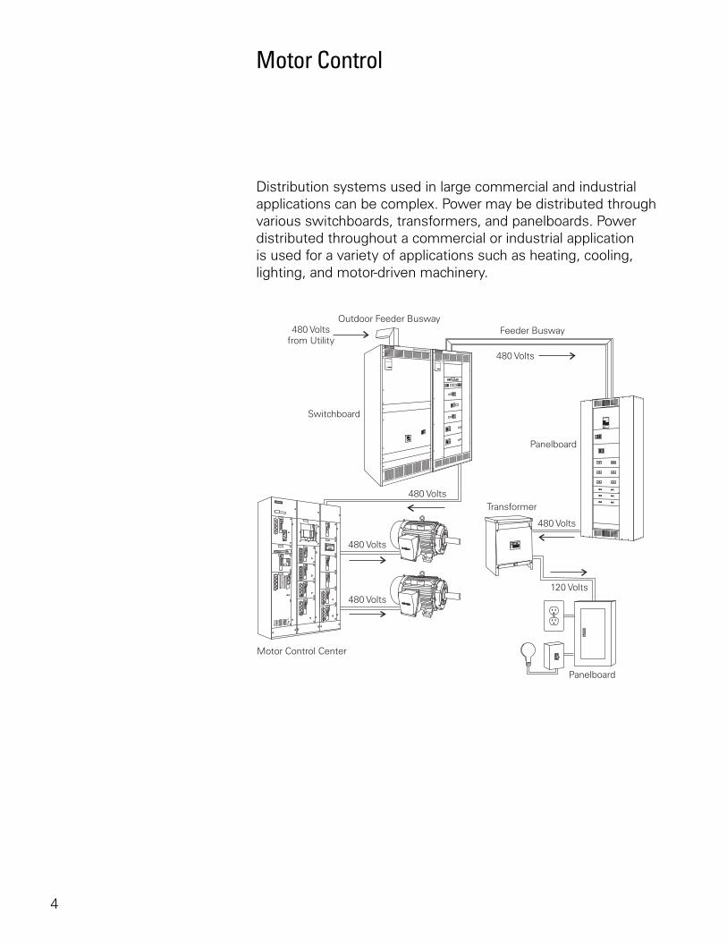
Distribution systems used in large commercial and industrial applications can be complex. Power may be distributed through various switchboards, transformers, and panelboards. Power distributed throughout a commercial or industrial application is used for a variety of applications such as heating, cooling, lighting, and motor-driven machinery.
5
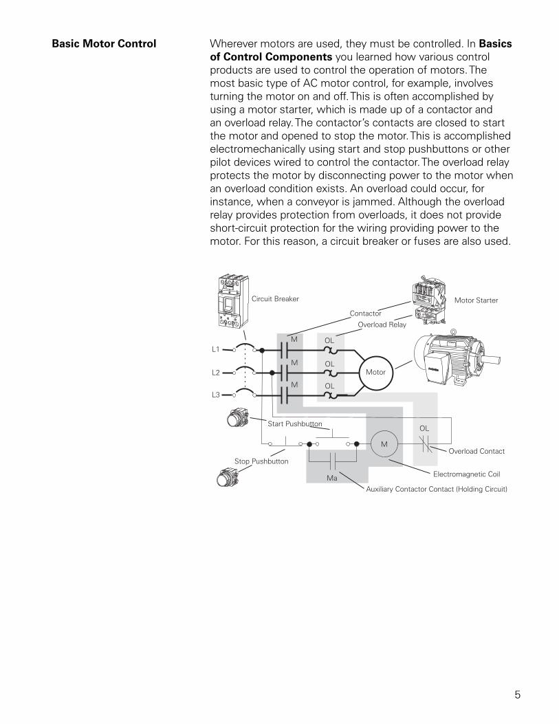
Basic Motor Control Wherever motors are used, they must be controlled. In Basics of Control Components you learned how various control products are used to control the operation of motors. The most basic type of AC motor control, for example, involves turning the motor on and off. This is often accomplished by using a motor starter, which is made up of a contactor and an overload relay. The contactor’s contacts are closed to start the motor and opened to stop the motor. This is accomplished electromechanically using start and stop pushbuttons or other pilot devices wired to control the contactor. The overload relay protects the motor by disconnecting power to the motor when an overload condition exists. An overload could occur, for instance, when a conveyor is jammed. Although the overload relay provides protection from overloads, it does not provide short-circuit protection for the wiring providing power to the motor. For this reason, a circuit breaker or fuses are also used.
6
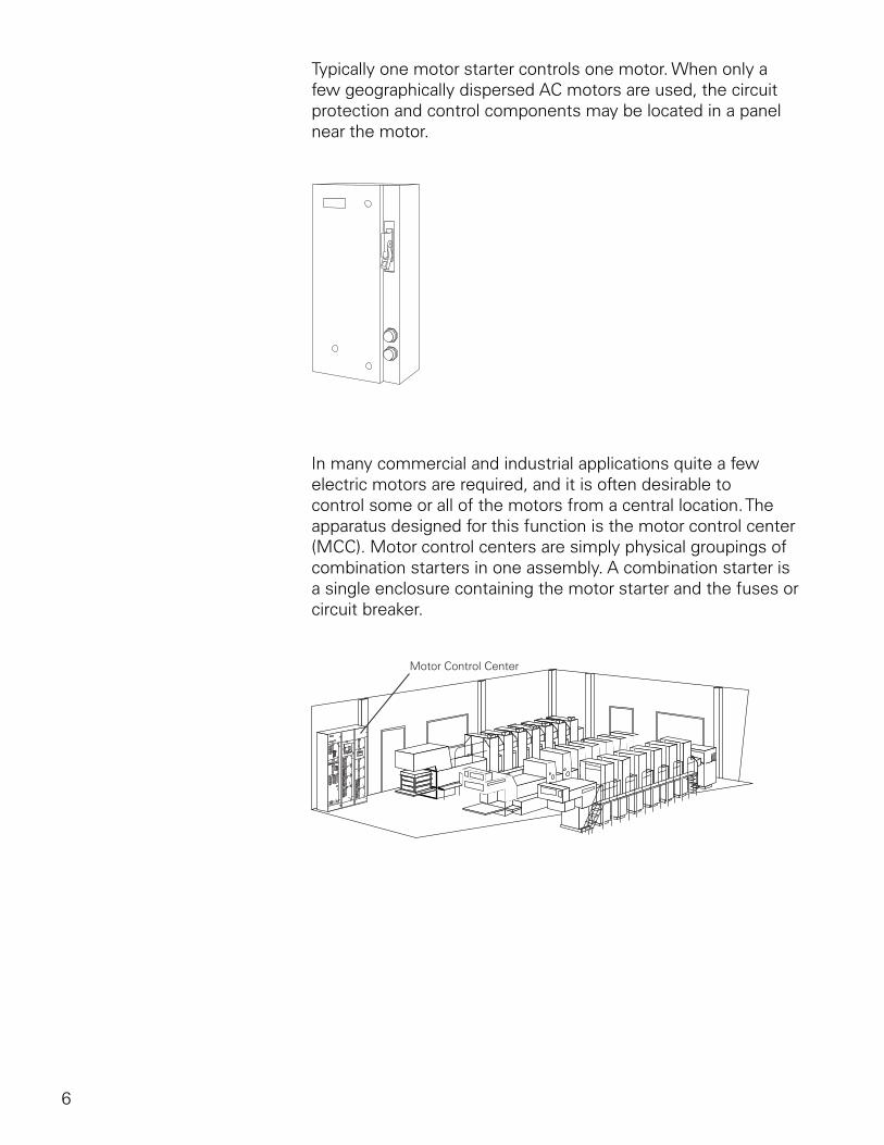
Typically one motor starter controls one motor. When only a few geographically dispersed AC motors are used, the circuit protection and control components may be located in a panel near the motor.
In many commercial and industrial applications quite a few electric motors are required, and it is often desirable to control some or all of the motors from a central location. The apparatus designed for this function is the motor control center (MCC). Motor control centers are simply physical groupings of combination starters in one assembly. A combination starter is a single enclosure containing the motor starter and the fuses or circuit breaker.
7
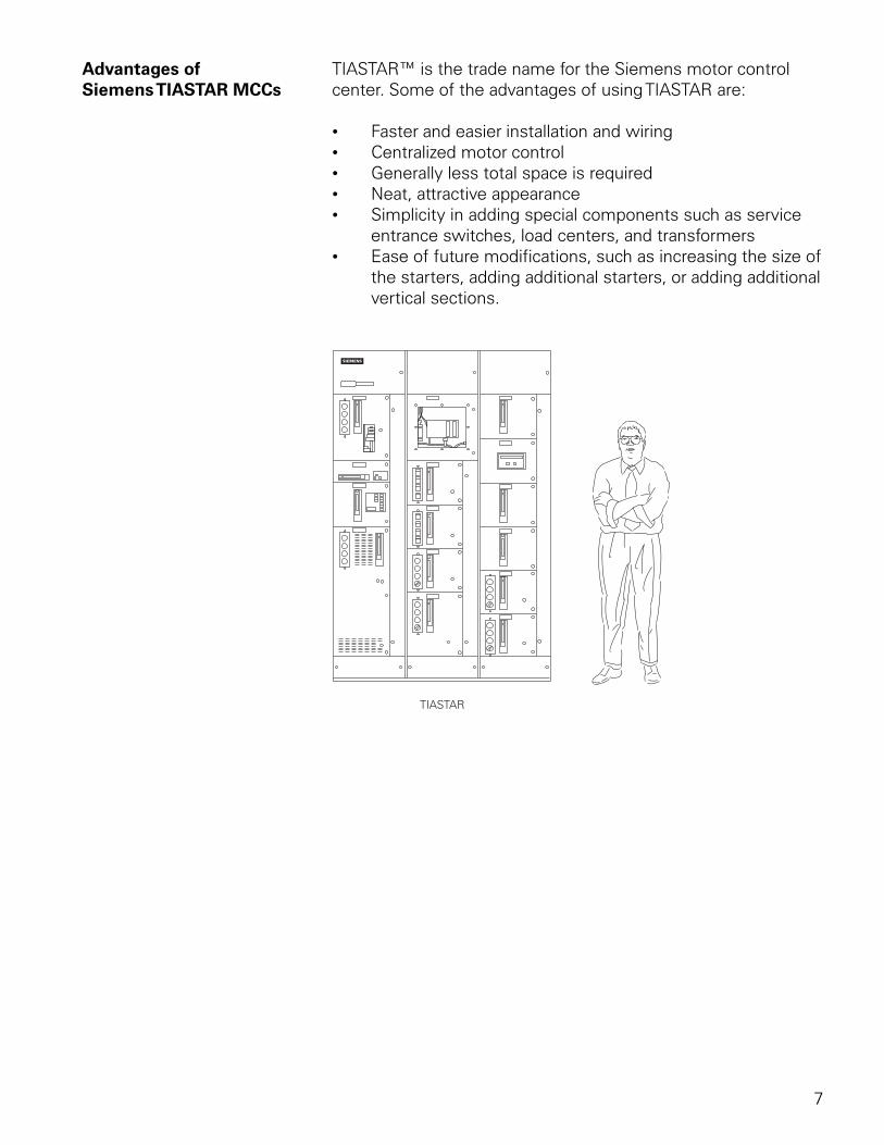
Advantages of TIASTAR™ is the trade name for the Siemens motor controlSiemens TIASTAR MCCs center. Some of the advantages of using TIASTAR are:
• Faster and easier installation and wiring• Centralized motor control• Generally less total space is required• Neat, attractive appearance• Simplicity in adding special components such as service
entrance switches, load centers, and transformers• Ease of future modifications, such as increasing the size of
the starters, adding additional starters, or adding additional vertical sections.
8
Power Supplies
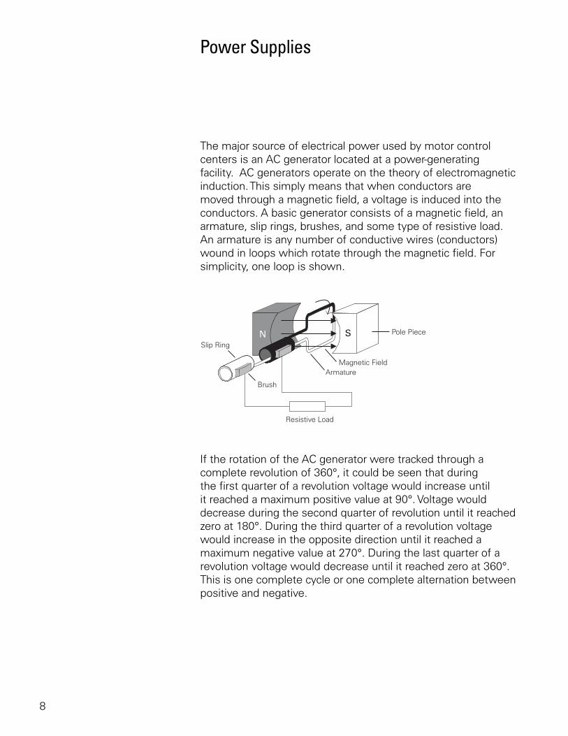
The major source of electrical power used by motor control centers is an AC generator located at a power-generating facility. AC generators operate on the theory of electromagnetic induction. This simply means that when conductors are moved through a magnetic field, a voltage is induced into the conductors. A basic generator consists of a magnetic field, an armature, slip rings, brushes, and some type of resistive load. An armature is any number of conductive wires (conductors) wound in loops which rotate through the magnetic field. For simplicity, one loop is shown.
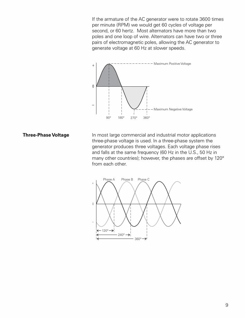
If the rotation of the AC generator were tracked through a complete revolution of 360°, it could be seen that during the first quarter of a revolution voltage would increase until it reached a maximum positive value at 90°. Voltage would decrease during the second quarter of revolution until it reached zero at 180°. During the third quarter of a revolution voltage would increase in the opposite direction until it reached a maximum negative value at 270°. During the last quarter of a revolution voltage would decrease until it reached zero at 360°. This is one complete cycle or one complete alternation between positive and negative.
9
If the armature of the AC generator were to rotate 3600 times per minute (RPM) we would get 60 cycles of voltage per second, or 60 hertz. Most alternators have more than two poles and one loop of wire. Alternators can have two or three pairs of electromagnetic poles, allowing the AC generator to generate voltage at 60 Hz at slower speeds.
Three-Phase Voltage In most large commercial and industrial motor applications three-phase voltage is used. In a three-phase system the generator produces three voltages. Each voltage phase rises and falls at the same frequency (60 Hz in the U.S., 50 Hz in many other countries); however, the phases are offset by 120° from each other.
10
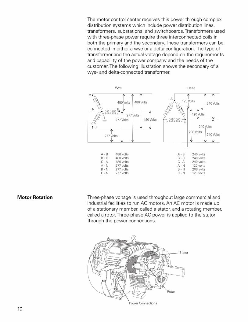
The motor control center receives this power through complex distribution systems which include power distribution lines, transformers, substations, and switchboards. Transformers used with three-phase power require three interconnected coils in both the primary and the secondary. These transformers can be connected in either a wye or a delta configuration. The type of transformer and the actual voltage depend on the requirements and capability of the power company and the needs of the customer. The following illustration shows the secondary of a wye- and delta-connected transformer.
Motor Rotation Three-phase voltage is used throughout large commercial and industrial facilities to run AC motors. An AC motor is made up of a stationary member, called a stator, and a rotating member, called a rotor. Three-phase AC power is applied to the stator through the power connections.
11
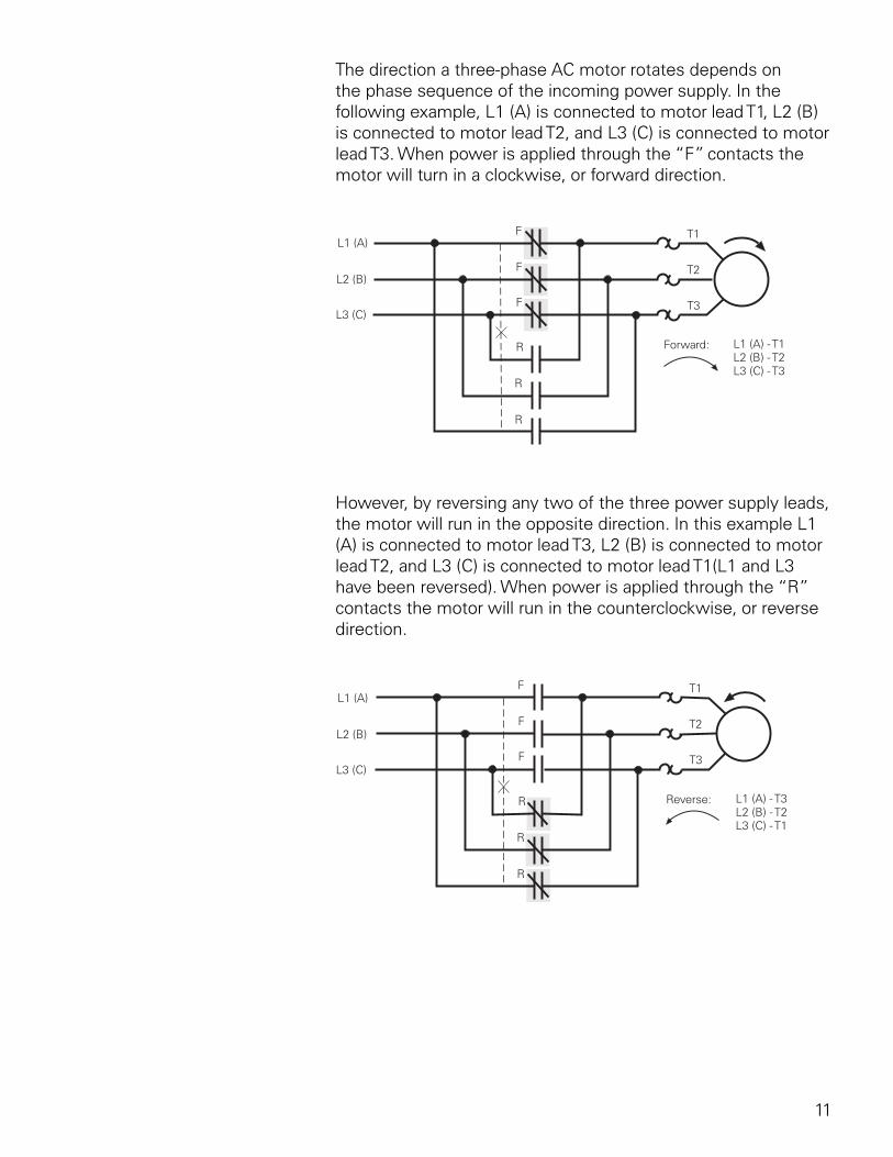
The direction a three-phase AC motor rotates depends on the phase sequence of the incoming power supply. In the following example, L1 (A) is connected to motor lead T1, L2 (B) is connected to motor lead T2, and L3 (C) is connected to motor lead T3. When power is applied through the “F” contacts the motor will turn in a clockwise, or forward direction.
However, by reversing any two of the three power supply leads, the motor will run in the opposite direction. In this example L1 (A) is connected to motor lead T3, L2 (B) is connected to motor lead T2, and L3 (C) is connected to motor lead T1(L1 and L3 have been reversed). When power is applied through the “R” contacts the motor will run in the counterclockwise, or reverse direction.
12
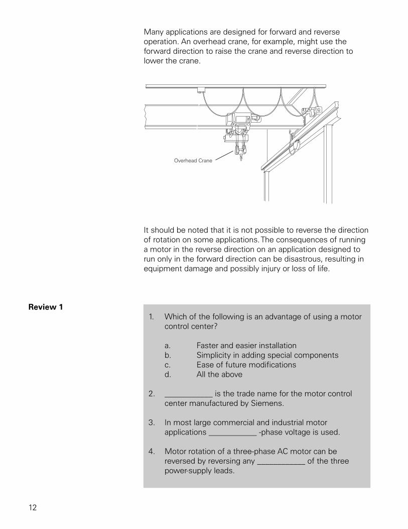
Many applications are designed for forward and reverse operation. An overhead crane, for example, might use the forward direction to raise the crane and reverse direction to lower the crane.
It should be noted that it is not possible to reverse the direction of rotation on some applications. The consequences of running a motor in the reverse direction on an application designed to run only in the forward direction can be disastrous, resulting in equipment damage and possibly injury or loss of life.
Review 1 1. Which of the following is an advantage of using a motor
control center?
a. Faster and easier installation b. Simplicity in adding special components c. Ease of future modifications d. All the above
2. ____________ is the trade name for the motor control center manufactured by Siemens.
3. In most large commercial and industrial motor applications ____________ -phase voltage is used.
4. Motor rotation of a three-phase AC motor can be reversed by reversing any ____________ of the three power-supply leads.
13
Design Standards
Although several organizations are involved in establishing standards for the design, construction, and application of motor control centers, the primary standards are established by UL, NEMA, and the National Electrical Code® (NEC®). The following organizations have established standards which may be applied to motor control centers. It is beyond the scope of this course to cover every standard; however, reference will be made throughout the course to many important standards with which Siemens motor control centers comply.
UL Underwriters Laboratories (UL) is a private company that is nationally recognized as an independent testing laboratory. UL tests products for safety and products that pass UL tests can carry a UL mark. Siemens motor control centers are designed to UL 845 standards.
NEMA The National Electrical Manufacturers Association (NEMA) is an organization that, among other things, develops standards for electrical equipment.
NEC The National Fire Protection Association (NFPA) is a nonprofit organization which publishes the National Electrical Code® (NEC®). The intent of the NEC® is to describe safe electrical practices.
ANSI The American National Standards Institute (ANSI) is a nongovernmental organization that facilitates the development of standards by establishing a consensus among qualified groups.
IEEE The Institute of Electrical and Electronic Engineers (IEEE) is an organization open to individual membership and provides a variety of services for its members. It also develops numerous standards for electrical and electronic equipment and practices.
IEC The International Electrotechnical Commission (IEC) is an organization based in Geneva, Switzerland, with over 50 member nations. IEC writes standards for electrical and electronic equipment practices.
NEC® and National Electrical Code® are registered trademarks of the National Fire Protection Association.
14
Need for Circuit Protection
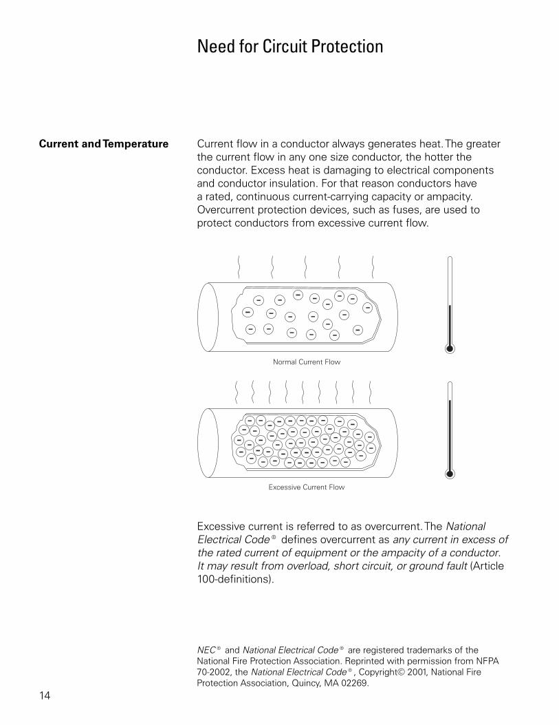
Current and Temperature Current flow in a conductor always generates heat. The greater the current flow in any one size conductor, the hotter the conductor. Excess heat is damaging to electrical components and conductor insulation. For that reason conductors have a rated, continuous current-carrying capacity or ampacity. Overcurrent protection devices, such as fuses, are used to protect conductors from excessive current flow.
Excessive current is referred to as overcurrent. The National Electrical Code® defines overcurrent as any current in excess of the rated current of equipment or the ampacity of a conductor. It may result from overload, short circuit, or ground fault (Article 100-definitions).
NEC® and National Electrical Code® are registered trademarks of the National Fire Protection Association. Reprinted with permission from NFPA 70-2002, the National Electrical Code®, Copyright© 2001, National Fire Protection Association, Quincy, MA 02269.
15
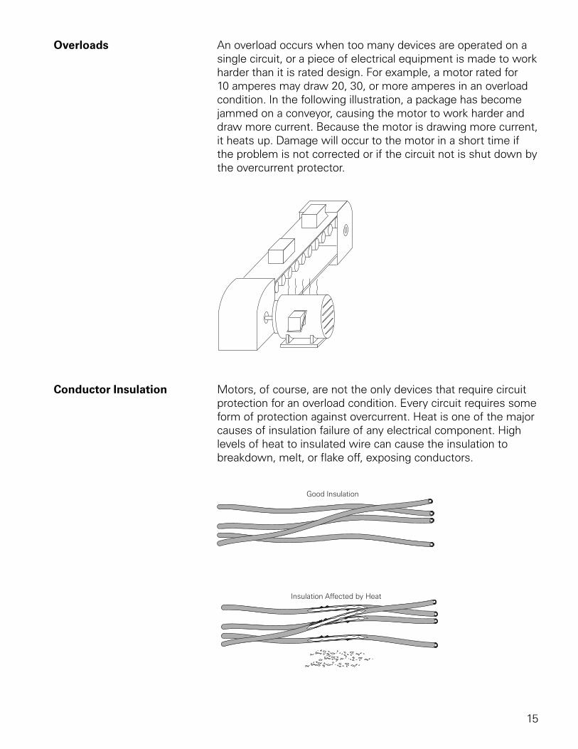
Overloads An overload occurs when too many devices are operated on a single circuit, or a piece of electrical equipment is made to work harder than it is rated design. For example, a motor rated for 10 amperes may draw 20, 30, or more amperes in an overload condition. In the following illustration, a package has become jammed on a conveyor, causing the motor to work harder and draw more current. Because the motor is drawing more current, it heats up. Damage will occur to the motor in a short time if the problem is not corrected or if the circuit not is shut down by the overcurrent protector.
Conductor Insulation Motors, of course, are not the only devices that require circuit protection for an overload condition. Every circuit requires some form of protection against overcurrent. Heat is one of the major causes of insulation failure of any electrical component. High levels of heat to insulated wire can cause the insulation to breakdown, melt, or flake off, exposing conductors.
16
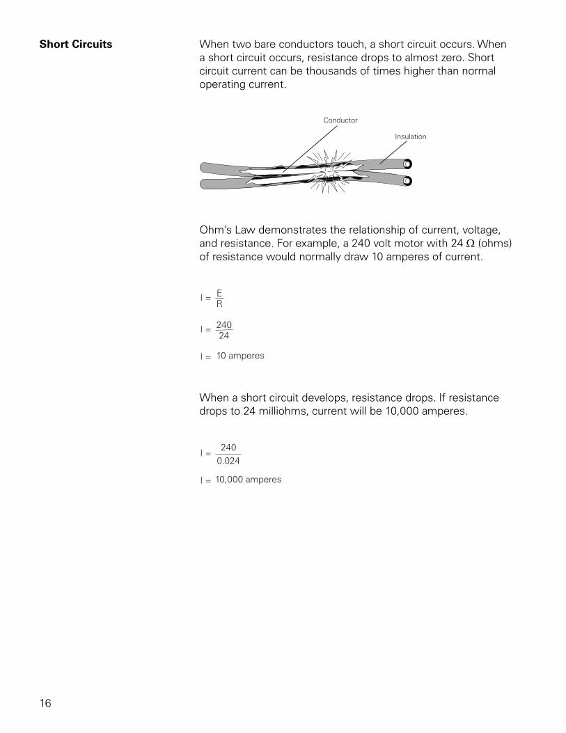
Short Circuits When two bare conductors touch, a short circuit occurs. When a short circuit occurs, resistance drops to almost zero. Short circuit current can be thousands of times higher than normal operating current.
Ohm’s Law demonstrates the relationship of current, voltage, and resistance. For example, a 240 volt motor with 24 Ω (ohms) of resistance would normally draw 10 amperes of current.
When a short circuit develops, resistance drops. If resistance drops to 24 milliohms, current will be 10,000 amperes.
17
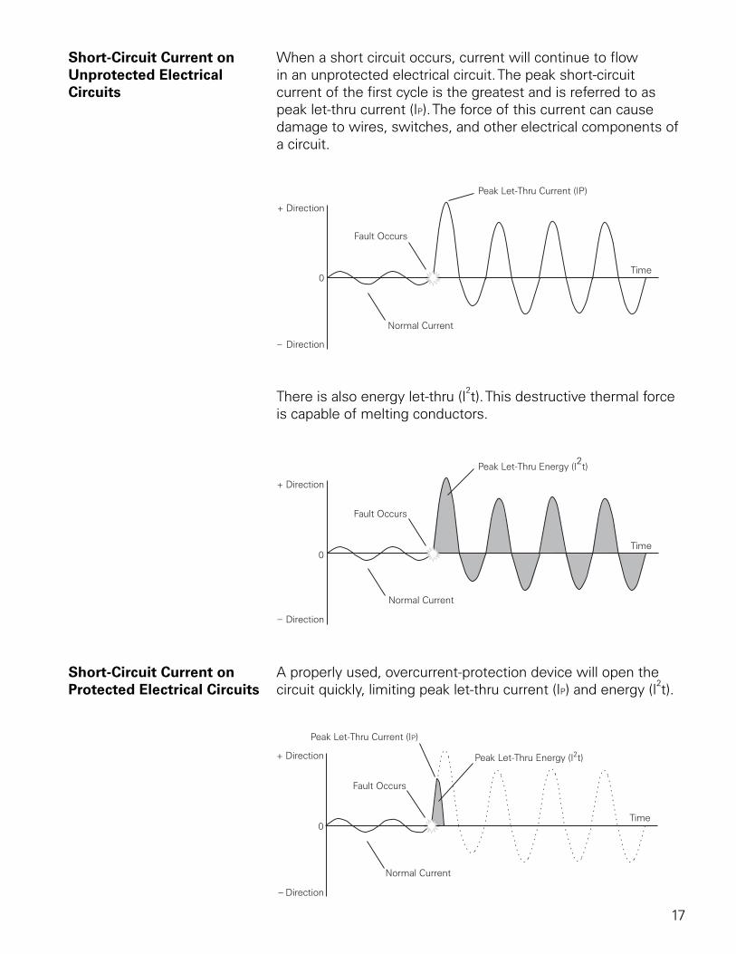
Short-Circuit Current on When a short circuit occurs, current will continue to flowUnprotected Electrical in an unprotected electrical circuit. The peak short-circuitCircuits current of the first cycle is the greatest and is referred to as
peak let-thru current (IP). The force of this current can cause damage to wires, switches, and other electrical components of a circuit.
There is also energy let-thru (I2t). This destructive thermal force
is capable of melting conductors.
Short-Circuit Current on A properly used, overcurrent-protection device will open theProtected Electrical Circuits circuit quickly, limiting peak let-thru current (IP) and energy (I
2t).
18
Article 240 Circuit protection would be unnecessary if overloads and short circuits could be eliminated. Unfortunately, overloads and short circuits do occur.
Article 240 of the NEC® covers overcurrent protection. You are encouraged to become familiar with this material. Article 240.1 states that:
Overcurrent protection for conductors and equipment is provided to open the circuit if the current reaches a value that will cause an excessive or dangerous temperature in conductors or conductor insulation.
Article 430.94 The National Electrical Code® requires overcurrent protection for motor control centers. NEC® article 430.94 states:
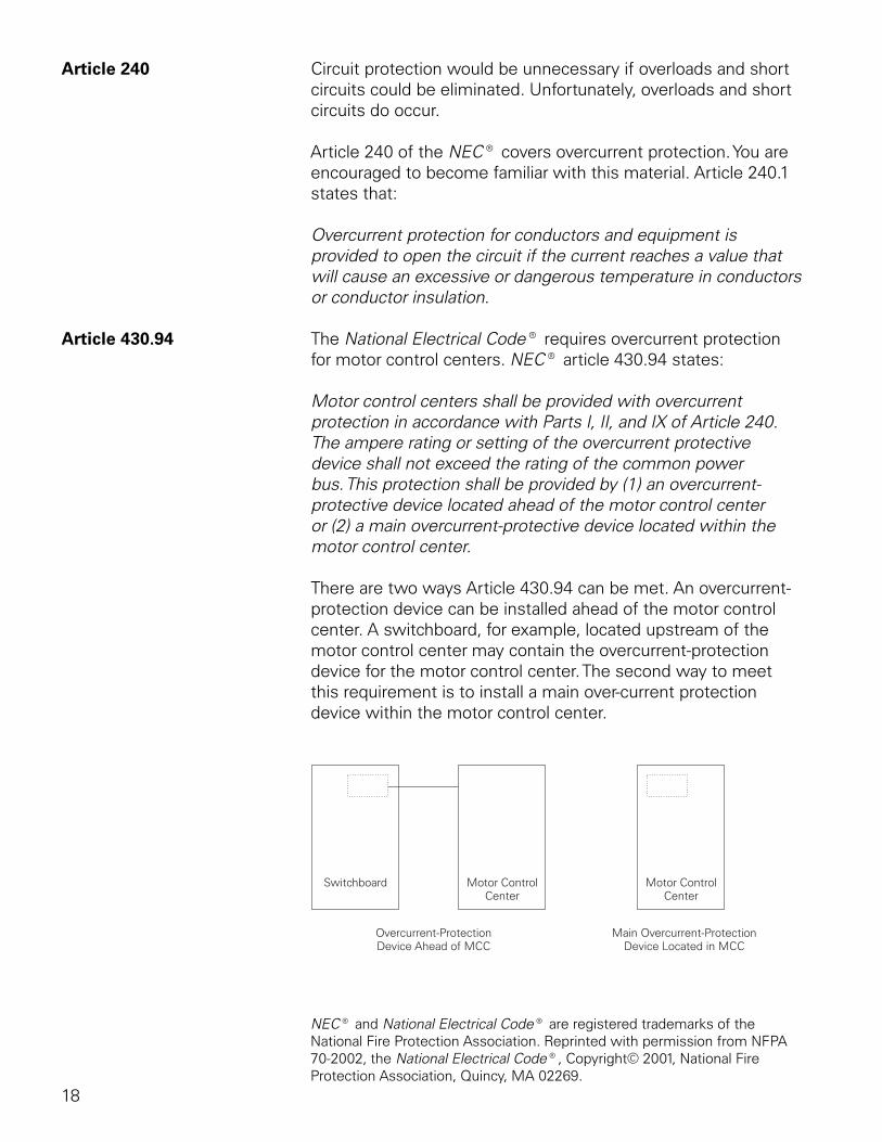
Motor control centers shall be provided with overcurrent protection in accordance with Parts I, II, and IX of Article 240. The ampere rating or setting of the overcurrent protective device shall not exceed the rating of the common power bus. This protection shall be provided by (1) an overcurrent-protective device located ahead of the motor control center or (2) a main overcurrent-protective device located within the motor control center.
There are two ways Article 430.94 can be met. An overcurrent-protection device can be installed ahead of the motor control center. A switchboard, for example, located upstream of the motor control center may contain the overcurrent-protection device for the motor control center. The second way to meet this requirement is to install a main over-current protection device within the motor control center.
NEC® and National Electrical Code® are registered trademarks of the National Fire Protection Association. Reprinted with permission from NFPA 70-2002, the National Electrical Code®, Copyright© 2001, National Fire Protection Association, Quincy, MA 02269.
19
Overcurrent-Protection Devices
An overcurrent-protection device must be able to recognize the difference between an overcurrent and short circuit and respond in the proper way. Slight overcurrents can be allowed to continue for some period of time; but as the current magnitude increases, the protection device must open faster. Short circuits must be interrupted instantly.
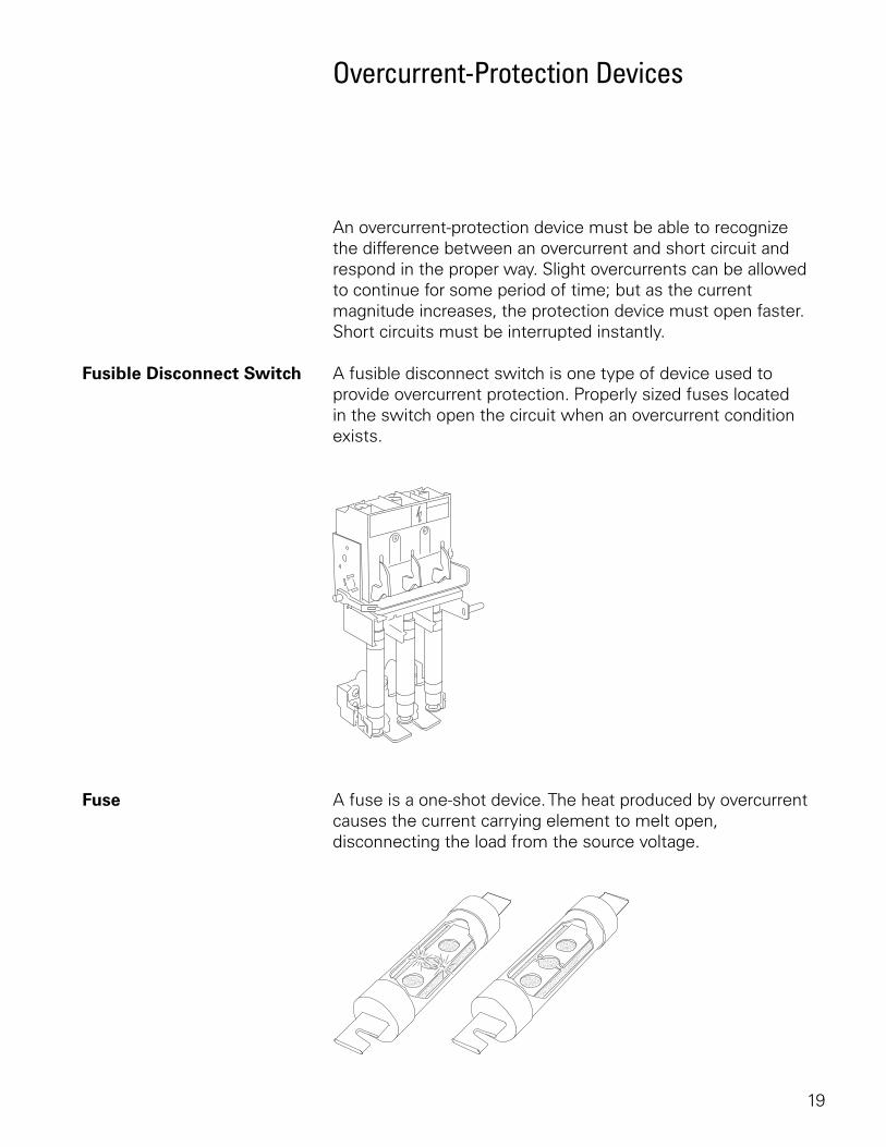
Fusible Disconnect Switch A fusible disconnect switch is one type of device used to provide overcurrent protection. Properly sized fuses located in the switch open the circuit when an overcurrent condition exists.
Fuse A fuse is a one-shot device. The heat produced by overcurrent causes the current carrying element to melt open, disconnecting the load from the source voltage.
20
Nontime-Delay Fuses Nontime-delay fuses provide excellent short-circuit protection. When an overcurrent occurs, heat builds up rapidly in the fuse. Nontime-delay fuses usually hold 500% of their rating for approximately one-fourth second, after which the current-carrying element melts. This means that these fuses should not be used in motor circuits which often have inrush currents greater than 500%.
Time-Delay Fuses Time-delay fuses provide overload and short-circuit protection. Time-delay fuses usually allow five times the rated current for up to ten seconds to allow motors to start.
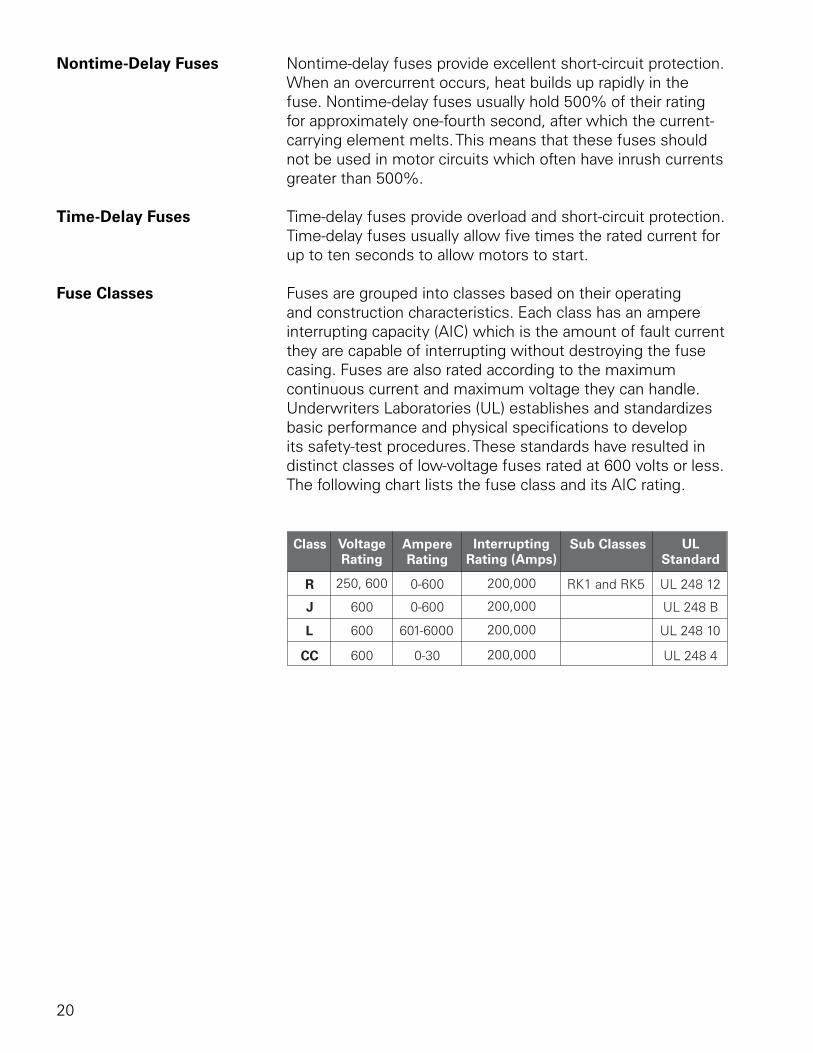
Fuse Classes Fuses are grouped into classes based on their operating and construction characteristics. Each class has an ampere interrupting capacity (AIC) which is the amount of fault current they are capable of interrupting without destroying the fuse casing. Fuses are also rated according to the maximum continuous current and maximum voltage they can handle. Underwriters Laboratories (UL) establishes and standardizes basic performance and physical specifications to develop its safety-test procedures. These standards have resulted in distinct classes of low-voltage fuses rated at 600 volts or less. The following chart lists the fuse class and its AIC rating.
21
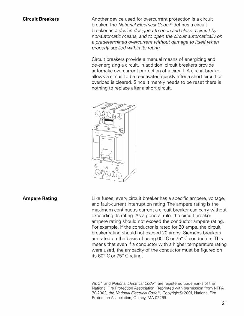
Circuit Breakers Another device used for overcurrent protection is a circuit breaker. The National Electrical Code® defines a circuit breaker as a device designed to open and close a circuit by nonautomatic means, and to open the circuit automatically on a predetermined overcurrent without damage to itself when properly applied within its rating.
Circuit breakers provide a manual means of energizing and de-energizing a circuit. In addition, circuit breakers provide automatic overcurrent protection of a circuit. A circuit breaker allows a circuit to be reactivated quickly after a short circuit or overload is cleared. Since it merely needs to be reset there is nothing to replace after a short circuit.
Ampere Rating Like fuses, every circuit breaker has a specific ampere, voltage, and fault-current interruption rating. The ampere rating is the maximum continuous current a circuit breaker can carry without exceeding its rating. As a general rule, the circuit breaker ampere rating should not exceed the conductor ampere rating. For example, if the conductor is rated for 20 amps, the circuit breaker rating should not exceed 20 amps. Siemens breakers are rated on the basis of using 60° C or 75° C conductors. This means that even if a conductor with a higher temperature rating were used, the ampacity of the conductor must be figured on its 60° C or 75° C rating.
NEC® and National Electrical Code® are registered trademarks of the National Fire Protection Association. Reprinted with permission from NFPA 70-2002, the National Electrical Code®, Copyright© 2001, National Fire Protection Association, Quincy, MA 02269.
22
There are some specific circumstances when the ampere rating is permitted to be greater than the current-carrying capacity of the circuit. For example, motor and welder circuits can exceed conductor ampacity to allow for inrush currents and duty cycles within limits established by NEC®.
Generally the ampere rating of a circuit breaker is selected at 125% of the continuous load current. This usually corresponds to the conductor ampacity which is also selected at 125% of continuous load current. For example, a 125 amp circuit breaker would be selected for a load of 100 amps.
Voltage Rating The voltage rating of the circuit breaker must be at least equal to the supply voltage. The voltage rating of a circuit breaker can be higher than the supply voltage, but never lower. For example, a 480 VAC circuit breaker could be used on a 240 VAC circuit. A 240 VAC circuit breaker could not be used on a 480 VAC circuit. The voltage rating is a function of the circuit breaker’s ability to suppress the internal arc that occurs when the circuit breaker’s contacts open.
Fault-Current Circuit breakers are also rated according to the level of faultInterrupting Rating current they can interrupt. When applying a circuit breaker, one
must be selected to sustain the largest potential short-circuit current which can occur in the selected application. Siemens circuit breakers have interrupting ratings from 10,000 to 200,000 amps.
Review 21. ____________ ____________ is a private company that
is nationally recognized as an independent testing laboratory.
2. The ____________ ____________ ____________ ____________ publishes the National Electrical Code®
3. Class R fuses have an interupting rating of ____________ amps.
4. Installing an overcurrent protective device ahead of an MCC or installing a main overcurrent protective device within an MCC are two methods of meeting NEC® Article ____________ .
23
Motor Control Centers
NEMA Definition NEMA defines a motor control center in ICS-2-322 as being a floor-mounted assembly of one or more enclosed vertical sections having a horizontal common power bus and principally containing combination motor control units. These units are mounted one above the other in the vertical sections. The sections may incorporate vertical buses connected to the common power bus, thus extending the common power supply to the individual units. Units may also connect directly to the common power bus by suitable wiring.
According to the NEMA definition, motor control centers:
• Are floor-mounted assemblies
• Have one or more enclosed vertical sections
• Have a common horizontal power bus
• May incorporate vertical buses connected to the common bus
• Principally contain combination motor control units
24
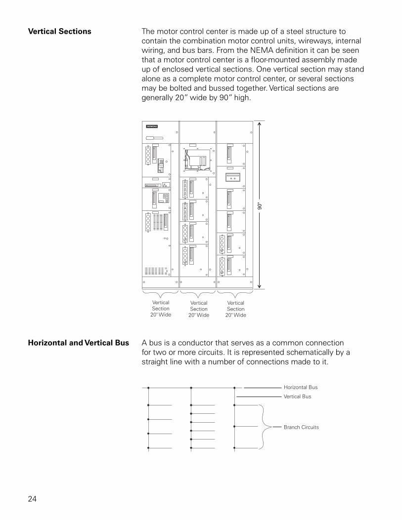
Vertical Sections The motor control center is made up of a steel structure to contain the combination motor control units, wireways, internal wiring, and bus bars. From the NEMA definition it can be seen that a motor control center is a floor-mounted assembly made up of enclosed vertical sections. One vertical section may stand alone as a complete motor control center, or several sections may be bolted and bussed together. Vertical sections are generally 20” wide by 90” high.
Horizontal and Vertical Bus A bus is a conductor that serves as a common connection for two or more circuits. It is represented schematically by a straight line with a number of connections made to it.
25
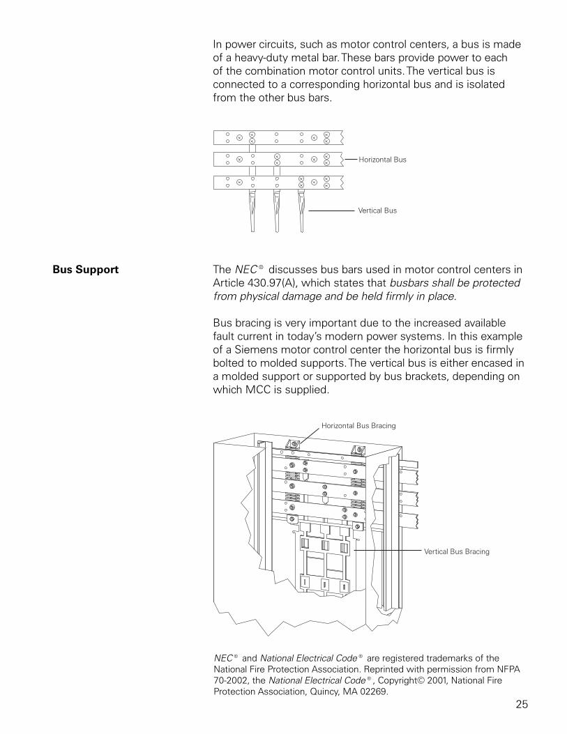
In power circuits, such as motor control centers, a bus is made of a heavy-duty metal bar. These bars provide power to each of the combination motor control units. The vertical bus is connected to a corresponding horizontal bus and is isolated from the other bus bars.
Bus Support The NEC® discusses bus bars used in motor control centers in Article 430.97(A), which states that busbars shall be protected from physical damage and be held firmly in place.
Bus bracing is very important due to the increased available fault current in today’s modern power systems. In this example of a Siemens motor control center the horizontal bus is firmly bolted to molded supports. The vertical bus is either encased in a molded support or supported by bus brackets, depending on which MCC is supplied.
NEC® and National Electrical Code® are registered trademarks of the National Fire Protection Association. Reprinted with permission from NFPA 70-2002, the National Electrical Code®, Copyright© 2001, National Fire Protection Association, Quincy, MA 02269.
26
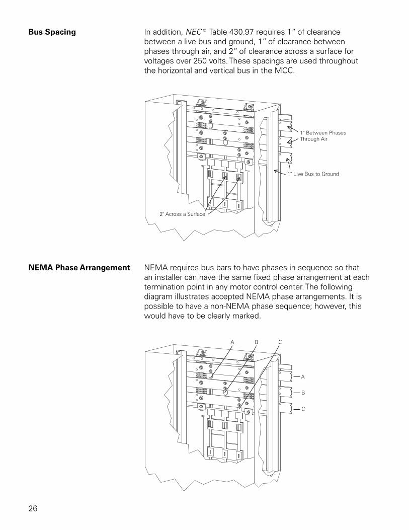
Bus Spacing In addition, NEC® Table 430.97 requires 1” of clearance between a live bus and ground, 1” of clearance between phases through air, and 2” of clearance across a surface for voltages over 250 volts. These spacings are used throughout the horizontal and vertical bus in the MCC.
NEMA Phase Arrangement NEMA requires bus bars to have phases in sequence so that an installer can have the same fixed phase arrangement at each termination point in any motor control center. The following diagram illustrates accepted NEMA phase arrangements. It is possible to have a non-NEMA phase sequence; however, this would have to be clearly marked.
27
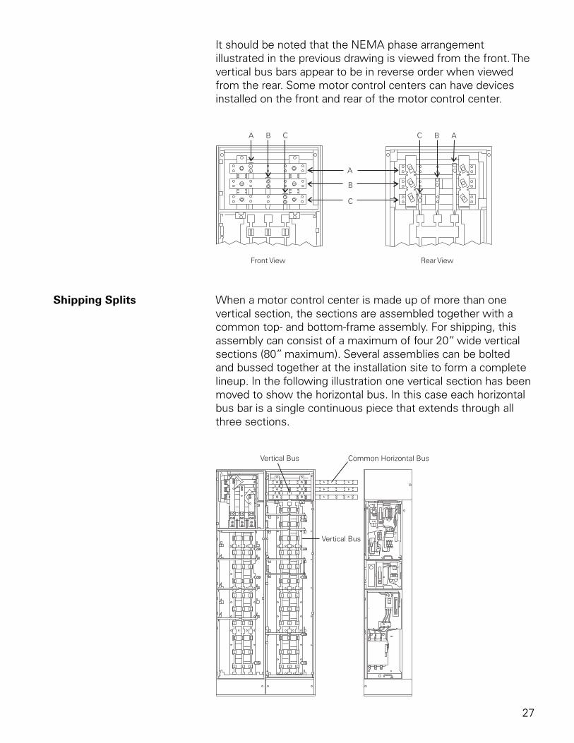
It should be noted that the NEMA phase arrangement illustrated in the previous drawing is viewed from the front. The vertical bus bars appear to be in reverse order when viewed from the rear. Some motor control centers can have devices installed on the front and rear of the motor control center.
Shipping Splits When a motor control center is made up of more than one vertical section, the sections are assembled together with a common top- and bottom-frame assembly. For shipping, this assembly can consist of a maximum of four 20” wide vertical sections (80” maximum). Several assemblies can be bolted and bussed together at the installation site to form a complete lineup. In the following illustration one vertical section has been moved to show the horizontal bus. In this case each horizontal bus bar is a single continuous piece that extends through all three sections.
28
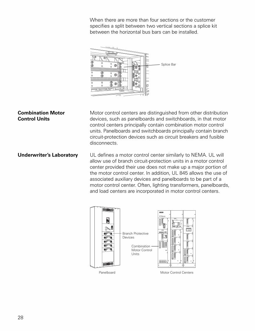
When there are more than four sections or the customer specifies a split between two vertical sections a splice kit between the horizontal bus bars can be installed.
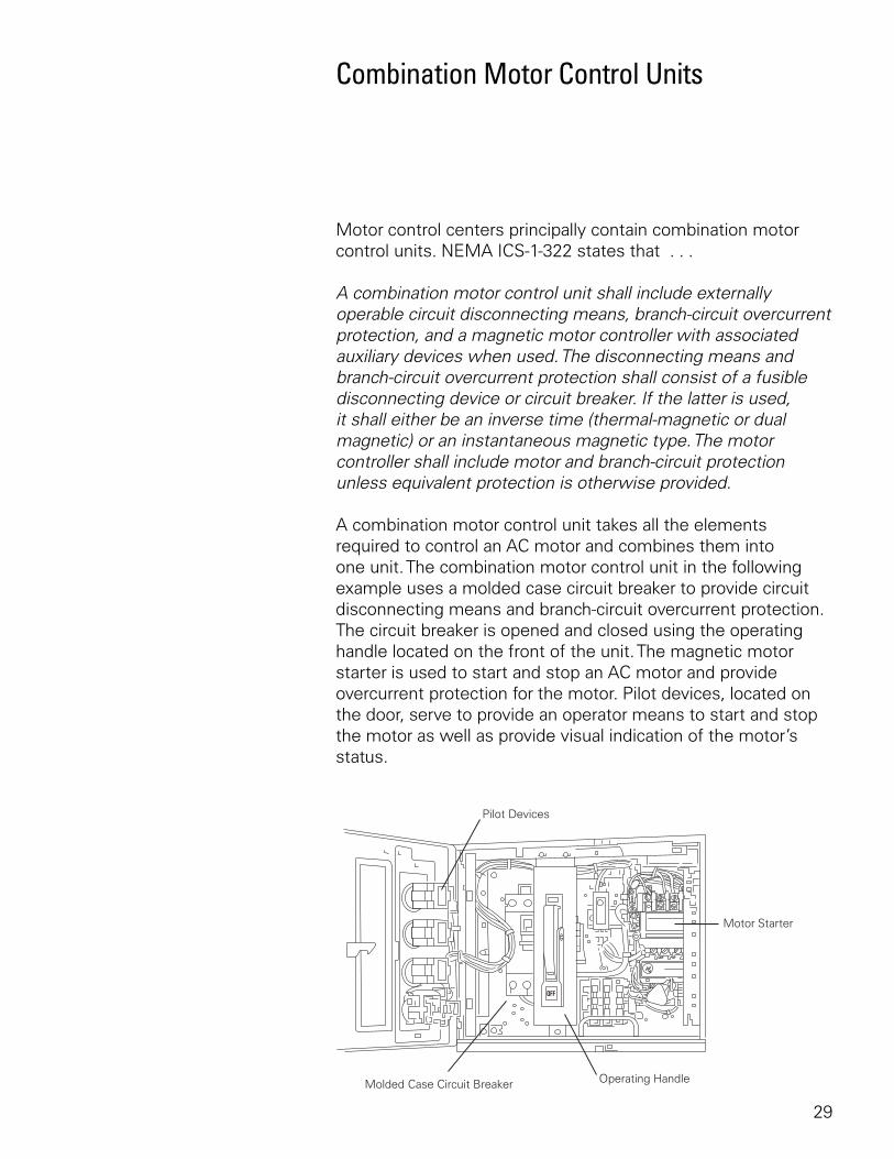
Combination Motor Motor control centers are distinguished from other distributionControl Units devices, such as panelboards and switchboards, in that motor
control centers principally contain combination motor control units. Panelboards and switchboards principally contain branch circuit-protection devices such as circuit breakers and fusible disconnects.
Underwriter’s Laboratory UL defines a motor control center similarly to NEMA. UL will allow use of branch circuit-protection units in a motor control center provided their use does not make up a major portion of the motor control center. In addition, UL 845 allows the use of associated auxiliary devices and panelboards to be part of a motor control center. Often, lighting transformers, panelboards, and load centers are incorporated in motor control centers.
29
Combination Motor Control Units
Motor control centers principally contain combination motor control units. NEMA ICS-1-322 states that . . .
A combination motor control unit shall include externally operable circuit disconnecting means, branch-circuit overcurrent protection, and a magnetic motor controller with associated auxiliary devices when used. The disconnecting means and branch-circuit overcurrent protection shall consist of a fusible disconnecting device or circuit breaker. If the latter is used, it shall either be an inverse time (thermal-magnetic or dual magnetic) or an instantaneous magnetic type. The motor controller shall include motor and branch-circuit protection unless equivalent protection is otherwise provided.
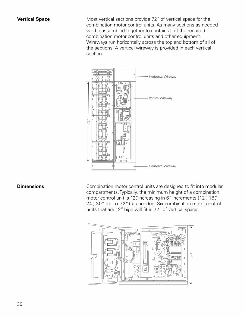
A combination motor control unit takes all the elements required to control an AC motor and combines them into one unit. The combination motor control unit in the following example uses a molded case circuit breaker to provide circuit disconnecting means and branch-circuit overcurrent protection. The circuit breaker is opened and closed using the operating handle located on the front of the unit. The magnetic motor starter is used to start and stop an AC motor and provide overcurrent protection for the motor. Pilot devices, located on the door, serve to provide an operator means to start and stop the motor as well as provide visual indication of the motor’s status.
30
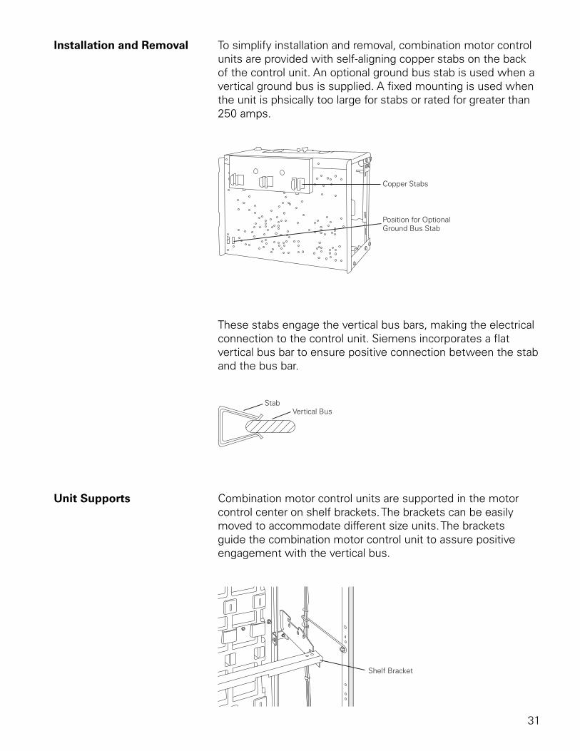
Vertical Space Most vertical sections provide 72” of vertical space for the combination motor control units. As many sections as needed will be assembled together to contain all of the required combination motor control units and other equipment. Wireways run horizontally across the top and bottom of all of the sections. A vertical wireway is provided in each vertical section.
Dimensions Combination motor control units are designed to fit into modular compartments. Typically, the minimum height of a combination motor control unit is 12”, increasing in 6” increments (12”, 18”, 24”, 30”, up to 72”) as needed. Six combination motor control units that are 12” high will fit in 72” of vertical space.
31
Installation and Removal To simplify installation and removal, combination motor control units are provided with self-aligning copper stabs on the back of the control unit. An optional ground bus stab is used when a vertical ground bus is supplied. A fixed mounting is used when the unit is phsically too large for stabs or rated for greater than 250 amps.
These stabs engage the vertical bus bars, making the electrical connection to the control unit. Siemens incorporates a flat vertical bus bar to ensure positive connection between the stab and the bus bar.
Unit Supports Combination motor control units are supported in the motor control center on shelf brackets. The brackets can be easily moved to accommodate different size units. The brackets guide the combination motor control unit to assure positive engagement with the vertical bus.
32
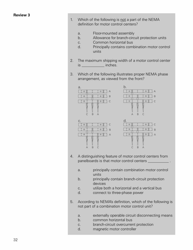
Review 3 1. Which of the following is not a part of the NEMA
definition for motor control centers?
a. Floor-mounted assembly b. Allowance for branch-circuit protection units c. Common horizontal bus d. Principally contains combination motor control units
2. The maximum shipping width of a motor control center is ____________ inches.
3. Which of the following illustrates proper NEMA phase arrangement, as viewed from the front?
4. A distinguishing feature of motor control centers from
panelboards is that motor control centers ___________ .
a. principally contain combination motor control units b. principally contain branch-circuit protection devices c. utilize both a horizontal and a vertical bus d. connect to three-phase power
5. According to NEMA’s definition, which of the following is not part of a combination motor control unit?
a. externally operable circuit disconnecting means b. common horizontal bus c. branch-circuit overcurrent protection d. magnetic motor controller
33
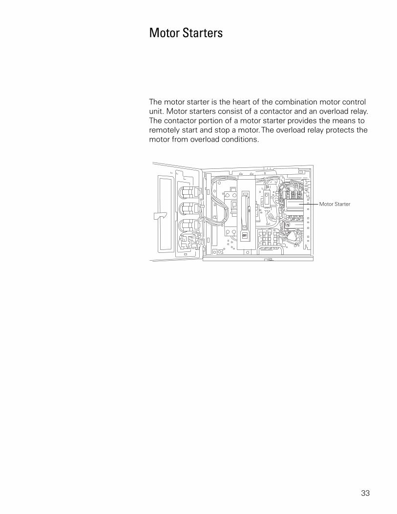
Motor Starters
The motor starter is the heart of the combination motor control unit. Motor starters consist of a contactor and an overload relay. The contactor portion of a motor starter provides the means to remotely start and stop a motor. The overload relay protects the motor from overload conditions.
34
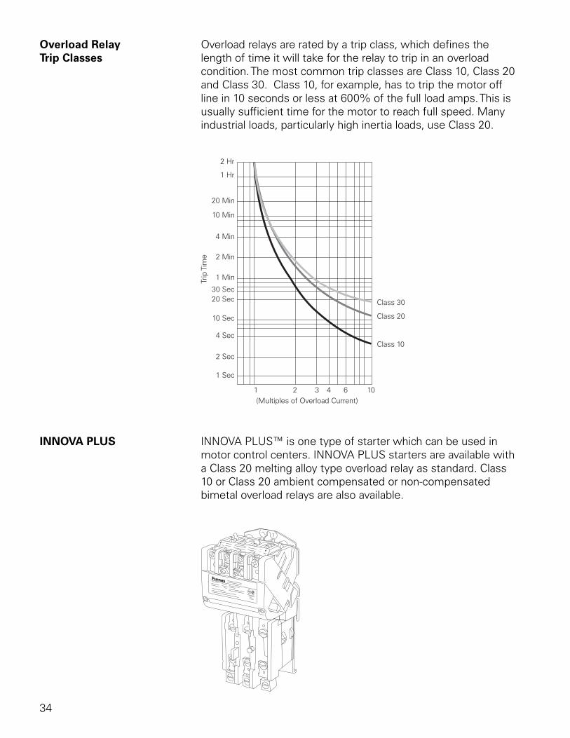
Overload Relay Overload relays are rated by a trip class, which defines theTrip Classes length of time it will take for the relay to trip in an overload
condition. The most common trip classes are Class 10, Class 20 and Class 30. Class 10, for example, has to trip the motor off line in 10 seconds or less at 600% of the full load amps. This is usually sufficient time for the motor to reach full speed. Many industrial loads, particularly high inertia loads, use Class 20.
INNOVA PLUS INNOVA PLUS™ is one type of starter which can be used in motor control centers. INNOVA PLUS starters are available with a Class 20 melting alloy type overload relay as standard. Class 10 or Class 20 ambient compensated or non-compensated bimetal overload relays are also available.
35
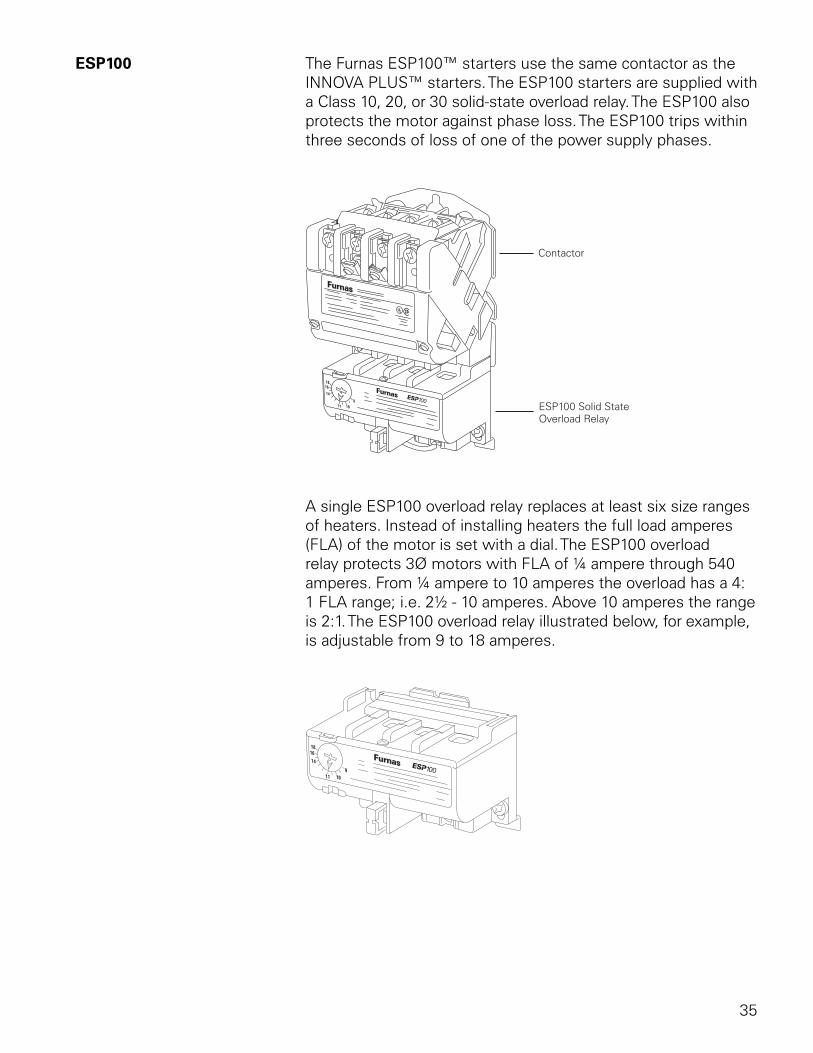
ESP100 The Furnas ESP100™ starters use the same contactor as the INNOVA PLUS™ starters. The ESP100 starters are supplied with a Class 10, 20, or 30 solid-state overload relay. The ESP100 also protects the motor against phase loss. The ESP100 trips within three seconds of loss of one of the power supply phases.
A single ESP100 overload relay replaces at least six size ranges of heaters. Instead of installing heaters the full load amperes (FLA) of the motor is set with a dial. The ESP100 overload relay protects 3Ø motors with FLA of ¼ ampere through 540 amperes. From ¼ ampere to 10 amperes the overload has a 4:1 FLA range; i.e. 2½ - 10 amperes. Above 10 amperes the range is 2:1. The ESP100 overload relay illustrated below, for example, is adjustable from 9 to 18 amperes.
36
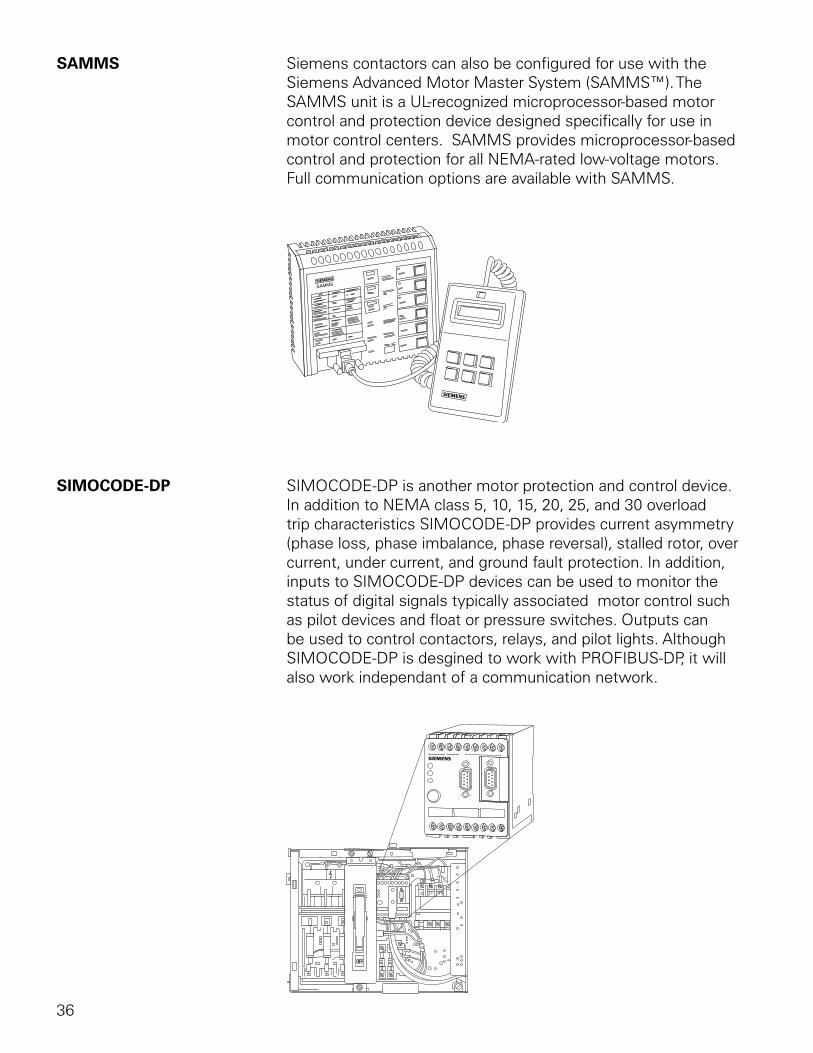
SAMMS Siemens contactors can also be configured for use with the Siemens Advanced Motor Master System (SAMMS™). The SAMMS unit is a UL-recognized microprocessor-based motor control and protection device designed specifically for use in motor control centers. SAMMS provides microprocessor-based control and protection for all NEMA-rated low-voltage motors. Full communication options are available with SAMMS.
SIMOCODE-DP SIMOCODE-DP is another motor protection and control device. In addition to NEMA class 5, 10, 15, 20, 25, and 30 overload trip characteristics SIMOCODE-DP provides current asymmetry (phase loss, phase imbalance, phase reversal), stalled rotor, over current, under current, and ground fault protection. In addition, inputs to SIMOCODE-DP devices can be used to monitor the status of digital signals typically associated motor control such as pilot devices and float or pressure switches. Outputs can be used to control contactors, relays, and pilot lights. Although SIMOCODE-DP is desgined to work with PROFIBUS-DP, it will also work independant of a communication network.
37
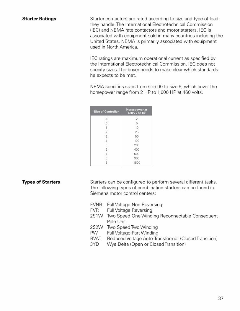
Starter Ratings Starter contactors are rated according to size and type of load they handle. The International Electrotechnical Commission (IEC) and NEMA rate contactors and motor starters. IEC is associated with equipment sold in many countries including the United States. NEMA is primarily associated with equipment used in North America.
IEC ratings are maximum operational current as specified by the International Electrotechnical Commission. IEC does not specify sizes. The buyer needs to make clear which standards he expects to be met.
NEMA specifies sizes from size 00 to size 9, which cover the horsepower range from 2 HP to 1,600 HP at 460 volts.
Types of Starters Starters can be configured to perform several different tasks. The following types of combination starters can be found in Siemens motor control centers:
FVNR Full Voltage Non-ReversingFVR Full Voltage Reversing2S1W Two Speed One Winding Reconnectable Consequent Pole Unit2S2W Two Speed Two WindingPW Full Voltage Part WindingRVAT Reduced Voltage Auto-Transformer (Closed Transition)3YD Wye Delta (Open or Closed Transition)
38
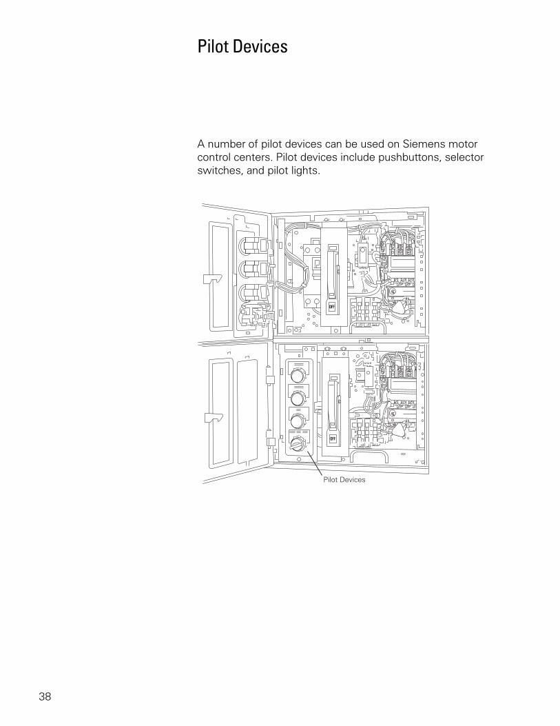
Pilot Devices
A number of pilot devices can be used on Siemens motor control centers. Pilot devices include pushbuttons, selector switches, and pilot lights.
39
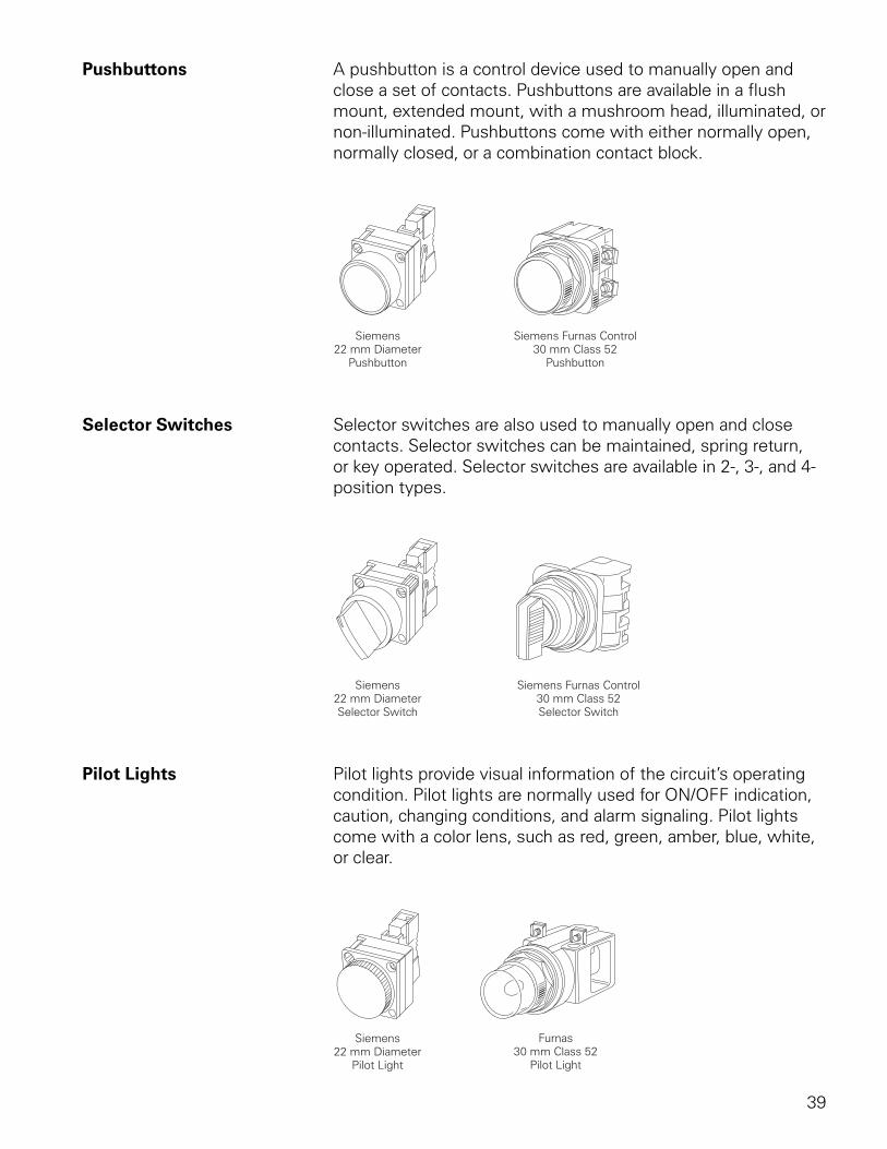
Pushbuttons A pushbutton is a control device used to manually open and close a set of contacts. Pushbuttons are available in a flush mount, extended mount, with a mushroom head, illuminated, or non-illuminated. Pushbuttons come with either normally open, normally closed, or a combination contact block.
Selector Switches Selector switches are also used to manually open and close contacts. Selector switches can be maintained, spring return, or key operated. Selector switches are available in 2-, 3-, and 4-position types.
Pilot Lights Pilot lights provide visual information of the circuit’s operating condition. Pilot lights are normally used for ON/OFF indication, caution, changing conditions, and alarm signaling. Pilot lights come with a color lens, such as red, green, amber, blue, white, or clear.
40
Circuit Breakers
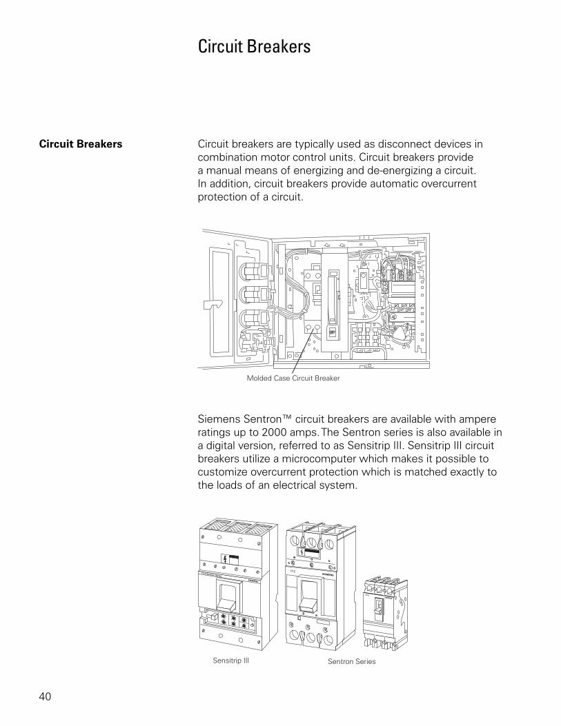
Circuit Breakers Circuit breakers are typically used as disconnect devices in combination motor control units. Circuit breakers provide a manual means of energizing and de-energizing a circuit. In addition, circuit breakers provide automatic overcurrent protection of a circuit.
Siemens Sentron™ circuit breakers are available with ampere ratings up to 2000 amps. The Sentron series is also available in a digital version, referred to as Sensitrip III. Sensitrip III circuit breakers utilize a microcomputer which makes it possible to customize overcurrent protection which is matched exactly to the loads of an electrical system.
41
Circuit Breaker Ratings There are two types of circuit breakers that are typically used in motor control centers. Thermal-magnetic circuit breakers have both overload and instantaneous trip features. When an overload condition exists, the excess current generates heat, which is detected in the circuit breaker. After a short period of time, depending on the rating of the breaker and the amount of overload, the breaker will trip, disconnecting the load from the voltage source. If a short circuit occurs, the breaker responds instantaneously to the fault current and disconnects the circuit. This type of circuit breaker is used in applications where a motor starter is not used, such as a main disconnect for the MCC or a feeder tap unit. Thermal-magnetic circuit breakers are not used in conjuction with a motor starter.
Instantaneous trip-only circuit breakers are also referred to as magnetic only or Type ETI circuit breakers. Type ETI circuit breakers provide short circuit protection, but they do not provide overload protection. Type ETI circuit breakers are commonly used in combination motor control units where a motor starter, such as the Furnas ESP100, provides overload protection. ETI trip ranges are selected to meet maximum settings per NEC® table 430.52 and Article 430.52(C)(3). The instantaneous trip-only circuit breaker is factory set at the LOW position. In accordance with the National Electical Code®, the setting on an instantaneous trip circuit breaker may be increased over 800%, but cannot be increased over 1300% of full load amps for a NEMA B motor.
NEC® and National Electrical Code® are registered trademarks of the National Fire Protection Association.
42
Other Types of Units in MCCs
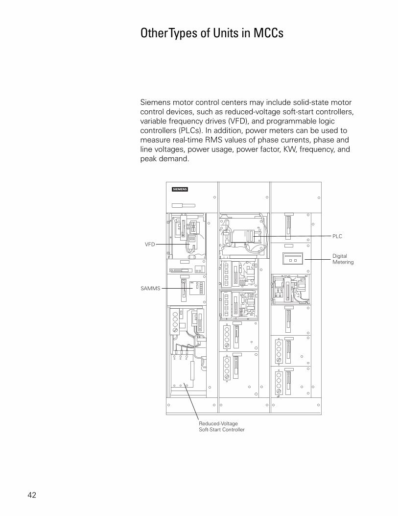
Siemens motor control centers may include solid-state motor control devices, such as reduced-voltage soft-start controllers, variable frequency drives (VFD), and programmable logic controllers (PLCs). In addition, power meters can be used to measure real-time RMS values of phase currents, phase and line voltages, power usage, power factor, KW, frequency, and peak demand.
43
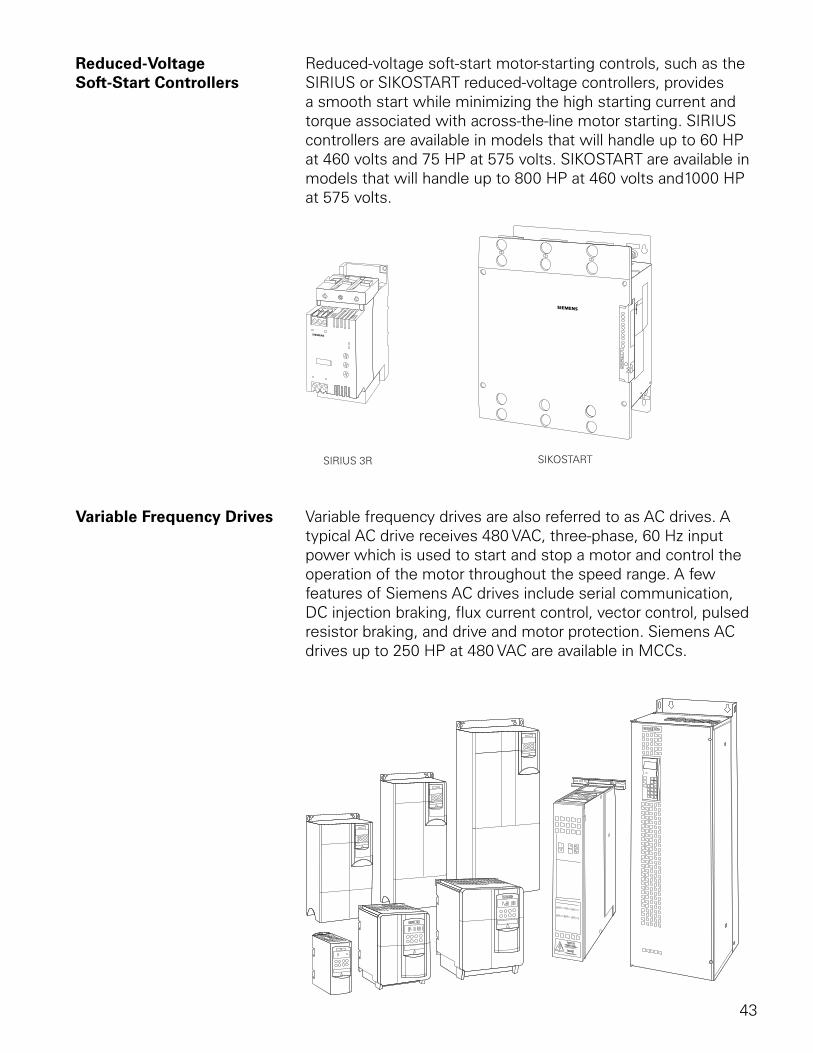
Reduced-Voltage Reduced-voltage soft-start motor-starting controls, such as theSoft-Start Controllers SIRIUS or SIKOSTART reduced-voltage controllers, provides
a smooth start while minimizing the high starting current and torque associated with across-the-line motor starting. SIRIUS controllers are available in models that will handle up to 60 HP at 460 volts and 75 HP at 575 volts. SIKOSTART are available in models that will handle up to 800 HP at 460 volts and1000 HP at 575 volts.
Variable Frequency Drives Variable frequency drives are also referred to as AC drives. A typical AC drive receives 480 VAC, three-phase, 60 Hz input power which is used to start and stop a motor and control the operation of the motor throughout the speed range. A few features of Siemens AC drives include serial communication, DC injection braking, flux current control, vector control, pulsed resistor braking, and drive and motor protection. Siemens AC drives up to 250 HP at 480 VAC are available in MCCs.
44
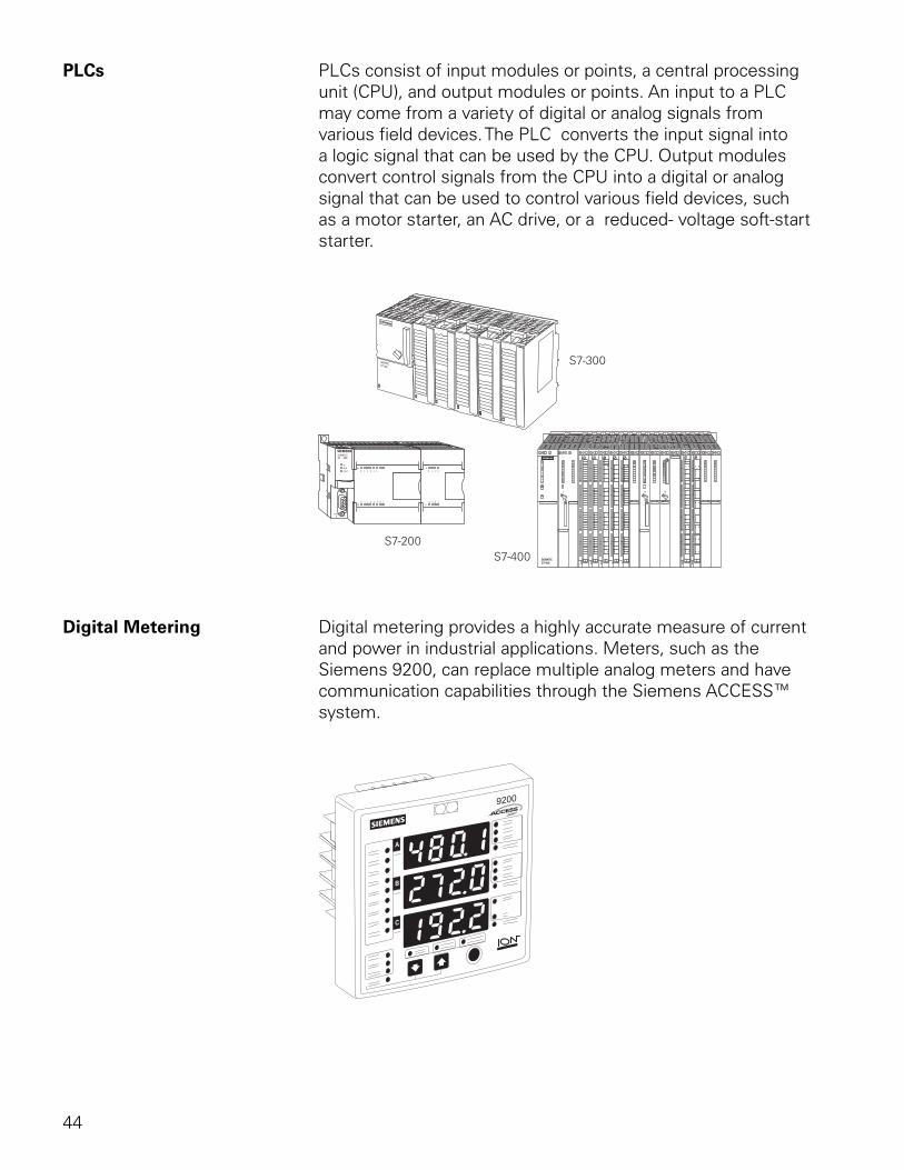
PLCs PLCs consist of input modules or points, a central processing unit (CPU), and output modules or points. An input to a PLC may come from a variety of digital or analog signals from various field devices. The PLC converts the input signal into a logic signal that can be used by the CPU. Output modules convert control signals from the CPU into a digital or analog signal that can be used to control various field devices, such as a motor starter, an AC drive, or a reduced- voltage soft-start starter.
Digital Metering Digital metering provides a highly accurate measure of current and power in industrial applications. Meters, such as the Siemens 9200, can replace multiple analog meters and have communication capabilities through the Siemens ACCESS™ system.
45
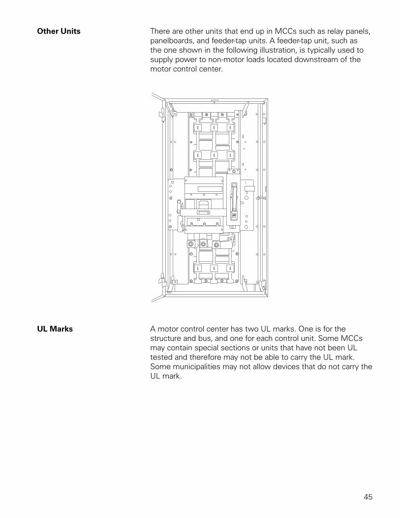
Other Units There are other units that end up in MCCs such as relay panels, panelboards, and feeder-tap units. A feeder-tap unit, such as the one shown in the following illustration, is typically used to supply power to non-motor loads located downstream of the motor control center.
UL Marks A motor control center has two UL marks. One is for the structure and bus, and one for each control unit. Some MCCs may contain special sections or units that have not been UL tested and therefore may not be able to carry the UL mark. Some municipalities may not allow devices that do not carry the UL mark.
46
Review 4 1. Class ____________ provides the highest level of
overload protection.
2. The ESP100 trips within ____________ seconds of loss of one of the power-supply phases.
3. A size 5 controller is rated for ____________ HP.
4. Which of the following devices can be used in a Siemens motor control center?
a. reduced-voltage starter b. variable frequency drive c. PLC d. SAMMS e. digital metering f. all of the above
5. ____________ and ____________ are Siemens trade names for a reduced-voltage soft-start controller.
47
MCC Ratings
In addition to the various ratings of individual components used in motor control centers, the overall ratings of the motor control center must also be considered.
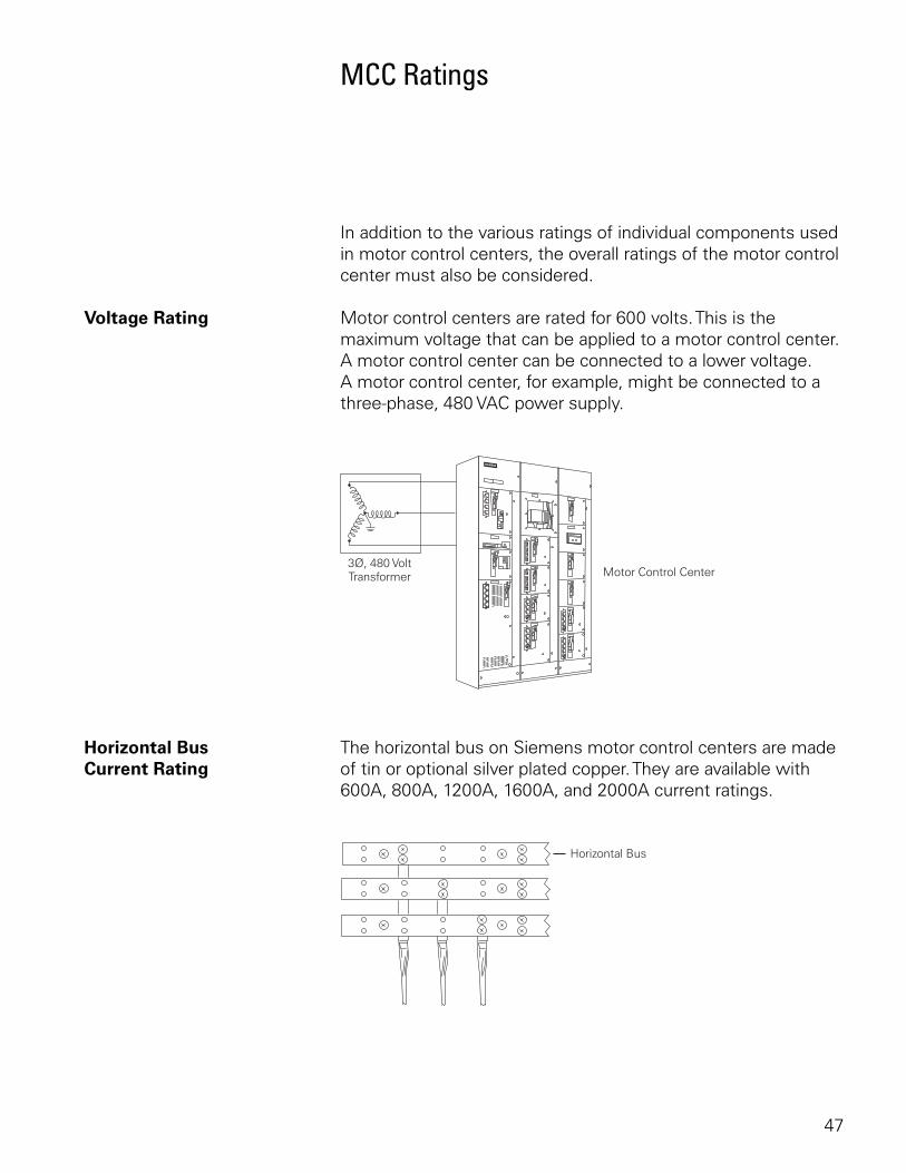
Voltage Rating Motor control centers are rated for 600 volts. This is the maximum voltage that can be applied to a motor control center. A motor control center can be connected to a lower voltage. A motor control center, for example, might be connected to a three-phase, 480 VAC power supply.
Horizontal Bus The horizontal bus on Siemens motor control centers are madeCurrent Rating of tin or optional silver plated copper. They are available with
600A, 800A, 1200A, 1600A, and 2000A current ratings.
48
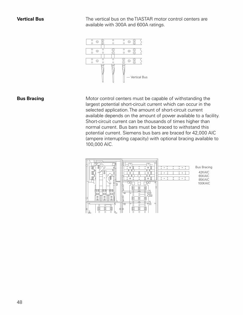
Vertical Bus The vertical bus on the TIASTAR motor control centers are available with 300A and 600A ratings.
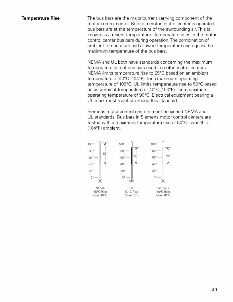
Bus Bracing Motor control centers must be capable of withstanding the largest potential short-circuit current which can occur in the selected application. The amount of short-circuit current available depends on the amount of power available to a facility. Short-circuit current can be thousands of times higher than normal current. Bus bars must be braced to withstand this potential current. Siemens bus bars are braced for 42,000 AIC (ampere interrupting capacity) with optional bracing available to 100,000 AIC.
49
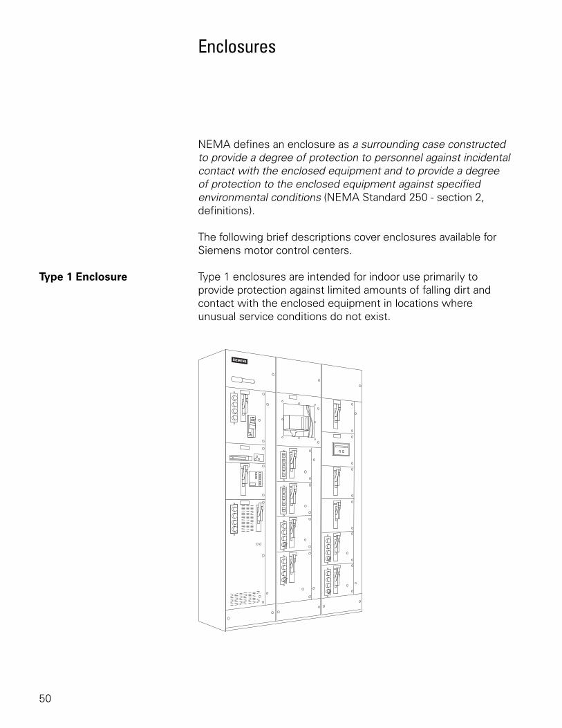
Temperature Rise The bus bars are the major current carrying component of the motor control center. Before a motor control center is operated, bus bars are at the temperature of the surrounding air. This is known as ambient temperature. Temperature rises in the motor control center bus bars during operation. The combination of ambient temperature and allowed temperature rise equals the maximum temperature of the bus bars.
NEMA and UL both have standards concerning the maximum temperature rise of bus bars used in motor control centers. NEMA limits temperature rise to 65°C based on an ambient temperature of 40°C (104°F), for a maximum operating temperature of 105°C. UL limits temperature rise to 50°C based on an ambient temperature of 40°C (104°F), for a maximum operating temperature of 90°C. Electrical equipment bearing a UL mark must meet or exceed this standard.
Siemens motor control centers meet or exceed NEMA and UL standards. Bus bars in Siemens motor control centers are tested with a maximum temperature rise of 50°C over 40°C (104°F) ambient.
50
Enclosures
NEMA defines an enclosure as a surrounding case constructed to provide a degree of protection to personnel against incidental contact with the enclosed equipment and to provide a degree of protection to the enclosed equipment against specified environmental conditions (NEMA Standard 250 - section 2, definitions).
The following brief descriptions cover enclosures available for Siemens motor control centers.
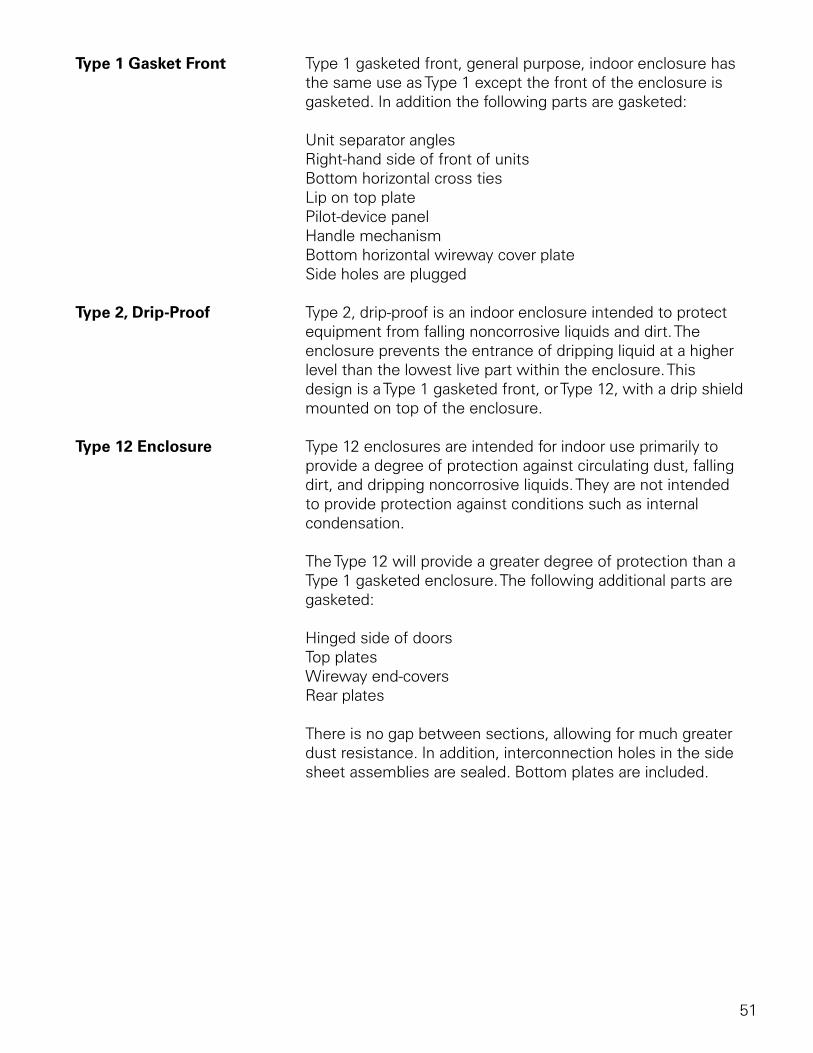
Type 1 Enclosure Type 1 enclosures are intended for indoor use primarily to provide protection against limited amounts of falling dirt and contact with the enclosed equipment in locations where unusual service conditions do not exist.
51
Type 1 Gasket Front Type 1 gasketed front, general purpose, indoor enclosure has the same use as Type 1 except the front of the enclosure is gasketed. In addition the following parts are gasketed:
Unit separator anglesRight-hand side of front of unitsBottom horizontal cross tiesLip on top platePilot-device panelHandle mechanismBottom horizontal wireway cover plateSide holes are plugged
Type 2, Drip-Proof Type 2, drip-proof is an indoor enclosure intended to protect equipment from falling noncorrosive liquids and dirt. The enclosure prevents the entrance of dripping liquid at a higher level than the lowest live part within the enclosure. This design is a Type 1 gasketed front, or Type 12, with a drip shield mounted on top of the enclosure.
Type 12 Enclosure Type 12 enclosures are intended for indoor use primarily to provide a degree of protection against circulating dust, falling dirt, and dripping noncorrosive liquids. They are not intended to provide protection against conditions such as internal condensation.
The Type 12 will provide a greater degree of protection than a Type 1 gasketed enclosure. The following additional parts are gasketed:
Hinged side of doorsTop platesWireway end-coversRear plates
There is no gap between sections, allowing for much greater dust resistance. In addition, interconnection holes in the side sheet assemblies are sealed. Bottom plates are included.
52
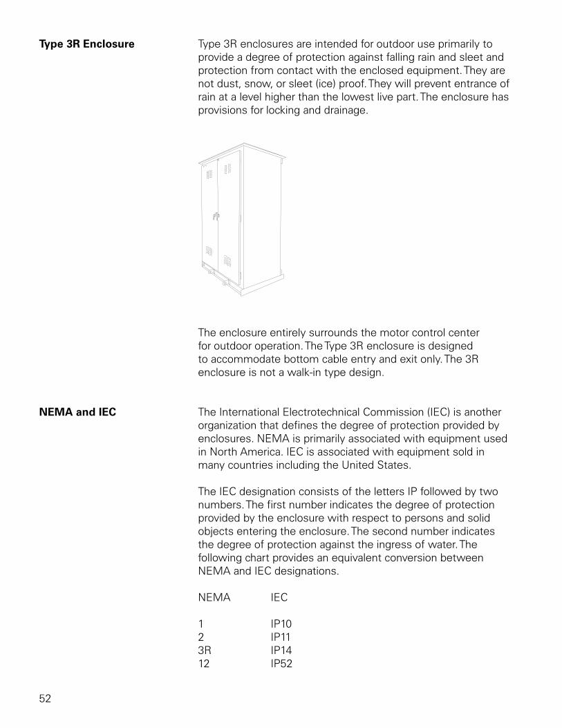
Type 3R Enclosure Type 3R enclosures are intended for outdoor use primarily to provide a degree of protection against falling rain and sleet and protection from contact with the enclosed equipment. They are not dust, snow, or sleet (ice) proof. They will prevent entrance of rain at a level higher than the lowest live part. The enclosure has provisions for locking and drainage.
The enclosure entirely surrounds the motor control center for outdoor operation. The Type 3R enclosure is designed to accommodate bottom cable entry and exit only. The 3R enclosure is not a walk-in type design.
NEMA and IEC The International Electrotechnical Commission (IEC) is another organization that defines the degree of protection provided by enclosures. NEMA is primarily associated with equipment used in North America. IEC is associated with equipment sold in many countries including the United States.
The IEC designation consists of the letters IP followed by two numbers. The first number indicates the degree of protection provided by the enclosure with respect to persons and solid objects entering the enclosure. The second number indicates the degree of protection against the ingress of water. The following chart provides an equivalent conversion between NEMA and IEC designations.
NEMA IEC
1 IP102 IP113R IP1412 IP52
53
Classification and Types of Wiring
NEMA has established two classification standards (Class I and Class II) and three types of wiring (A, B, and C) used in the construction of motor control centers. These are specified by the customer.
Class I Class I consists of a grouping of combination motor control units in which each starter and motor operates independently of the other starters. The factory connects the combination motor control units to the vertical bus but does not provide interconnecting wiring between combination motor control units, different vertical units, or remotely connected devices. Diagrams of the individual units only are supplied.
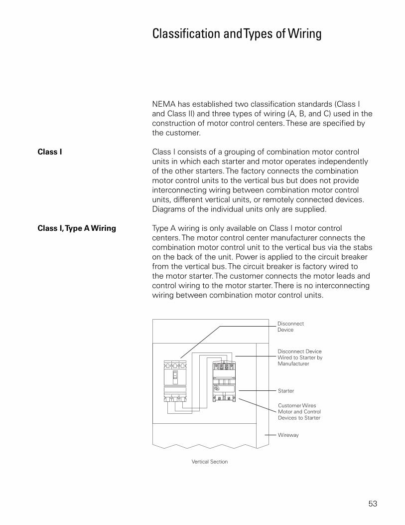
Class I, Type A Wiring Type A wiring is only available on Class I motor control centers. The motor control center manufacturer connects the combination motor control unit to the vertical bus via the stabs on the back of the unit. Power is applied to the circuit breaker from the vertical bus. The circuit breaker is factory wired to the motor starter. The customer connects the motor leads and control wiring to the motor starter. There is no interconnecting wiring between combination motor control units.
54
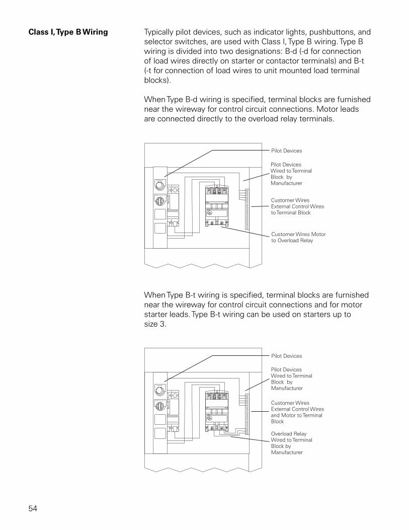
Class I, Type B Wiring Typically pilot devices, such as indicator lights, pushbuttons, and selector switches, are used with Class I, Type B wiring. Type B wiring is divided into two designations: B-d (-d for connection of load wires directly on starter or contactor terminals) and B-t (-t for connection of load wires to unit mounted load terminal blocks).
When Type B-d wiring is specified, terminal blocks are furnished near the wireway for control circuit connections. Motor leads are connected directly to the overload relay terminals.
When Type B-t wiring is specified, terminal blocks are furnished near the wireway for control circuit connections and for motor starter leads. Type B-t wiring can be used on starters up to size 3.
55
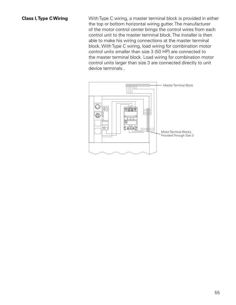
Class I, Type C Wiring With Type C wiring, a master terminal block is provided in either the top or bottom horizontal wiring gutter. The manufacturer of the motor control center brings the control wires from each control unit to the master terminal block. The installer is then able to make his wiring connections at the master terminal block. With Type C wiring, load wiring for combination motor control units smaller than size 3 (50 HP) are connected to the master terminal block. Load wiring for combination motor control units larger than size 3 are connected directly to unit device terminals..
56
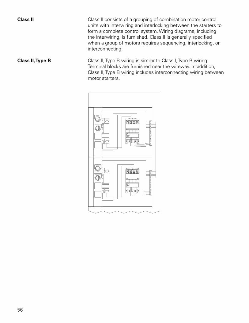
Class II Class II consists of a grouping of combination motor control units with interwiring and interlocking between the starters to form a complete control system. Wiring diagrams, including the interwiring, is furnished. Class II is generally specified when a group of motors requires sequencing, interlocking, or interconnecting.
Class II, Type B Class II, Type B wiring is similar to Class I, Type B wiring. Terminal blocks are furnished near the wireway. In addition, Class II, Type B wiring includes interconnecting wiring between motor starters.
57
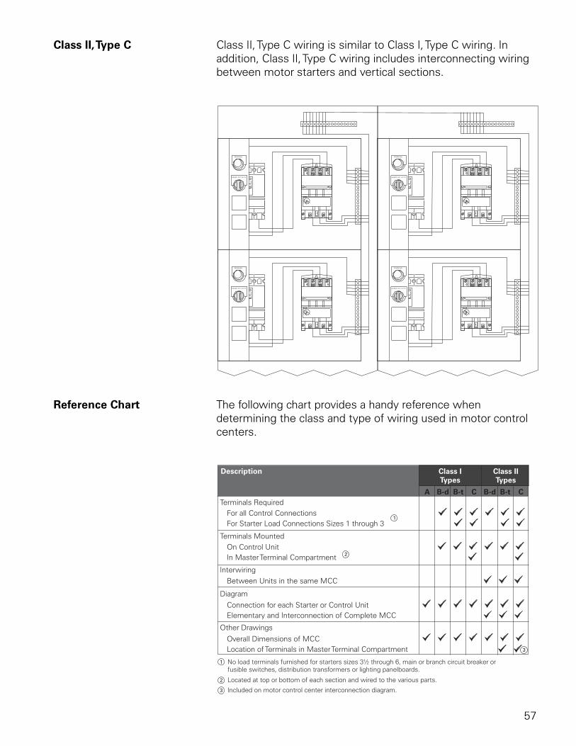
Class II, Type C Class II, Type C wiring is similar to Class I, Type C wiring. In addition, Class II, Type C wiring includes interconnecting wiring between motor starters and vertical sections.
Reference Chart The following chart provides a handy reference when determining the class and type of wiring used in motor control centers.
58
Cable Entry
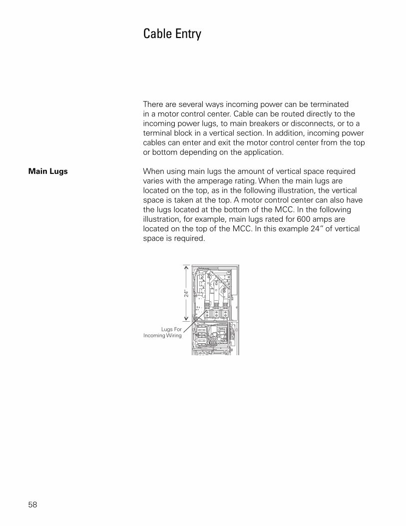
There are several ways incoming power can be terminated in a motor control center. Cable can be routed directly to the incoming power lugs, to main breakers or disconnects, or to a terminal block in a vertical section. In addition, incoming power cables can enter and exit the motor control center from the top or bottom depending on the application.
Main Lugs When using main lugs the amount of vertical space required varies with the amperage rating. When the main lugs are located on the top, as in the following illustration, the vertical space is taken at the top. A motor control center can also have the lugs located at the bottom of the MCC. In the following illustration, for example, main lugs rated for 600 amps are located on the top of the MCC. In this example 24” of vertical space is required.
59
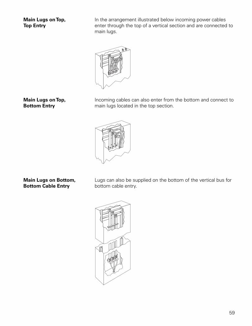
Main Lugs on Top, In the arrangement illustrated below incoming power cablesTop Entry enter through the top of a vertical section and are connected to
main lugs.
Main Lugs on Top, Incoming cables can also enter from the bottom and connect toBottom Entry main lugs located in the top section.
Main Lugs on Bottom, Lugs can also be supplied on the bottom of the vertical bus forBottom Cable Entry bottom cable entry.
60
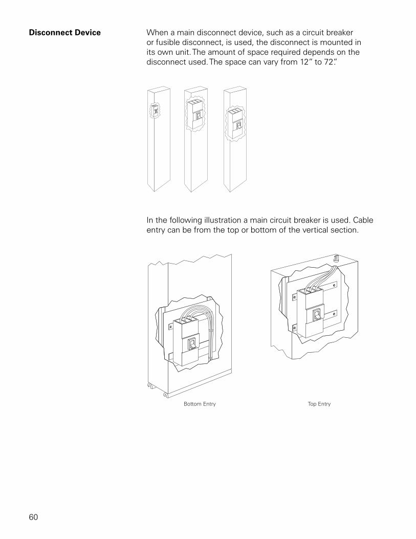
Disconnect Device When a main disconnect device, such as a circuit breaker or fusible disconnect, is used, the disconnect is mounted in its own unit. The amount of space required depends on the disconnect used. The space can vary from 12” to 72”.
In the following illustration a main circuit breaker is used. Cable entry can be from the top or bottom of the vertical section.
61
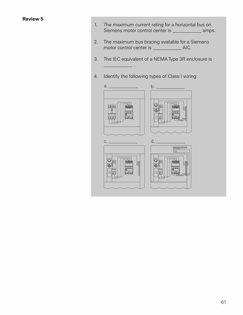
Review 5 1. The maximum current rating for a horizontal bus on
Siemens motor control center is ____________ amps.
2. The maximum bus bracing available for a Siemens motor control center is ____________ AIC.
3. The IEC equivalent of a NEMA Type 3R enclosure is ____________ .
4. Identify the following types of Class I wiring:
62
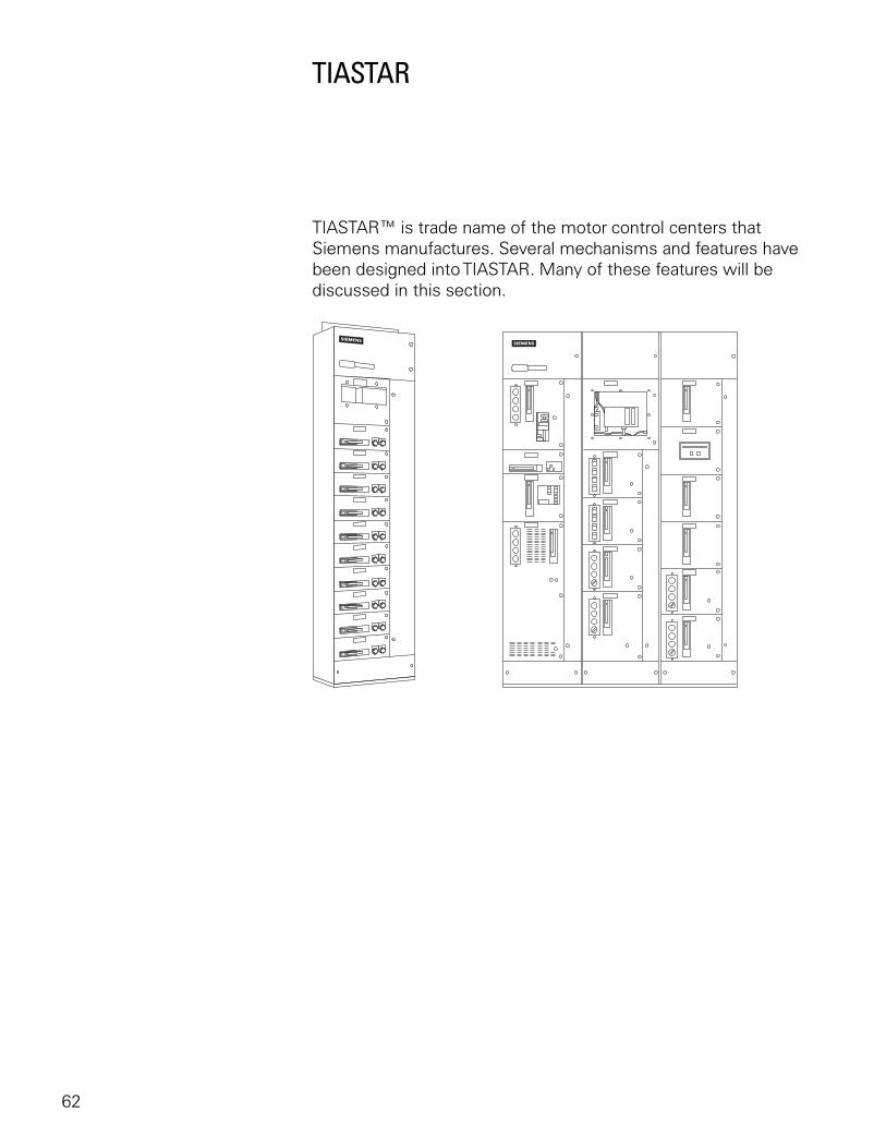
TIASTAR
TIASTAR™ is trade name of the motor control centers that Siemens manufactures. Several mechanisms and features have been designed into TIASTAR. Many of these features will be discussed in this section.
63
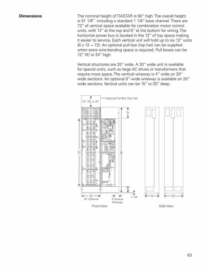
Dimensions The nominal height of TIASTAR is 90” high. The overall height is 91 1/8” including a standard 1 1/8” base channel. There are 72” of vertical space available for combination motor control units, with 12” at the top and 6” at the bottom for wiring. The horizontal power bus is located in the 12” of top space making it easier to service. Each vertical unit will hold up to six 12” units (6 x 12 = 72). An optional pull box (top hat) can be supplied when extra wire-bending space is required. Pull boxes can be 12”, 18”, or 24” high.
Vertical structures are 20” wide. A 30” wide unit is available for special units, such as large AC drives or transformers that require more space. The vertical wireway is 4” wide on 20” wide sections. An optional 8”-wide wireway is available on 20” wide sections. Vertical units can be 15” or 20” deep.
64
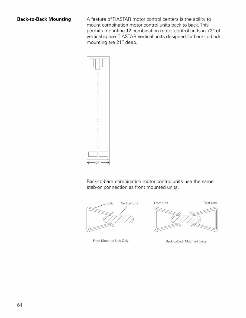
Back-to-Back Mounting A feature of TIASTAR motor control centers is the ability to mount combination motor control units back to back. This permits mounting 12 combination motor control units in 72” of vertical space. TIASTAR vertical units designed for back-to-back mounting are 21” deep.
Back-to-back combination motor control units use the same stab-on connection as front mounted units.
65
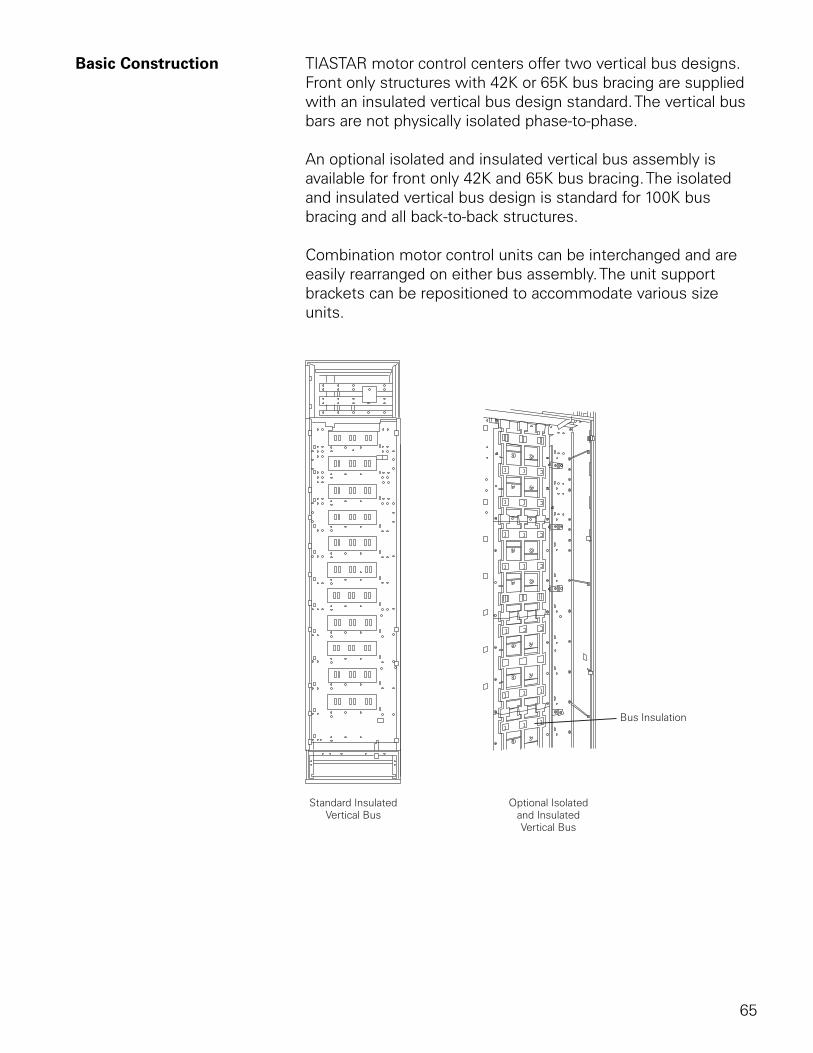
Basic Construction TIASTAR motor control centers offer two vertical bus designs. Front only structures with 42K or 65K bus bracing are supplied with an insulated vertical bus design standard. The vertical bus bars are not physically isolated phase-to-phase.
An optional isolated and insulated vertical bus assembly is available for front only 42K and 65K bus bracing. The isolated and insulated vertical bus design is standard for 100K bus bracing and all back-to-back structures.
Combination motor control units can be interchanged and are easily rearranged on either bus assembly. The unit support brackets can be repositioned to accommodate various size units.
66
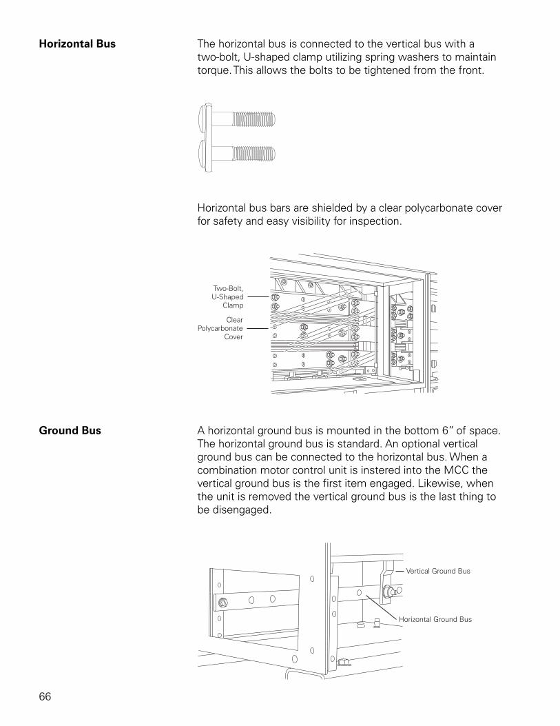
Horizontal Bus The horizontal bus is connected to the vertical bus with a two-bolt, U-shaped clamp utilizing spring washers to maintain torque. This allows the bolts to be tightened from the front.
Horizontal bus bars are shielded by a clear polycarbonate cover for safety and easy visibility for inspection.
Ground Bus A horizontal ground bus is mounted in the bottom 6” of space. The horizontal ground bus is standard. An optional vertical ground bus can be connected to the horizontal bus. When a combination motor control unit is instered into the MCC the vertical ground bus is the first item engaged. Likewise, when the unit is removed the vertical ground bus is the last thing to be disengaged.
67
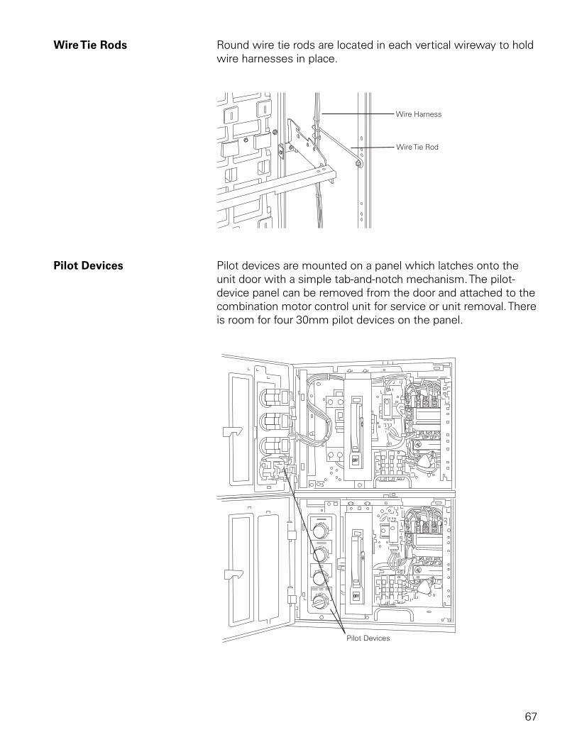
Wire Tie Rods Round wire tie rods are located in each vertical wireway to hold wire harnesses in place.
Pilot Devices Pilot devices are mounted on a panel which latches onto the unit door with a simple tab-and-notch mechanism. The pilot-device panel can be removed from the door and attached to the combination motor control unit for service or unit removal. There is room for four 30mm pilot devices on the panel.
68
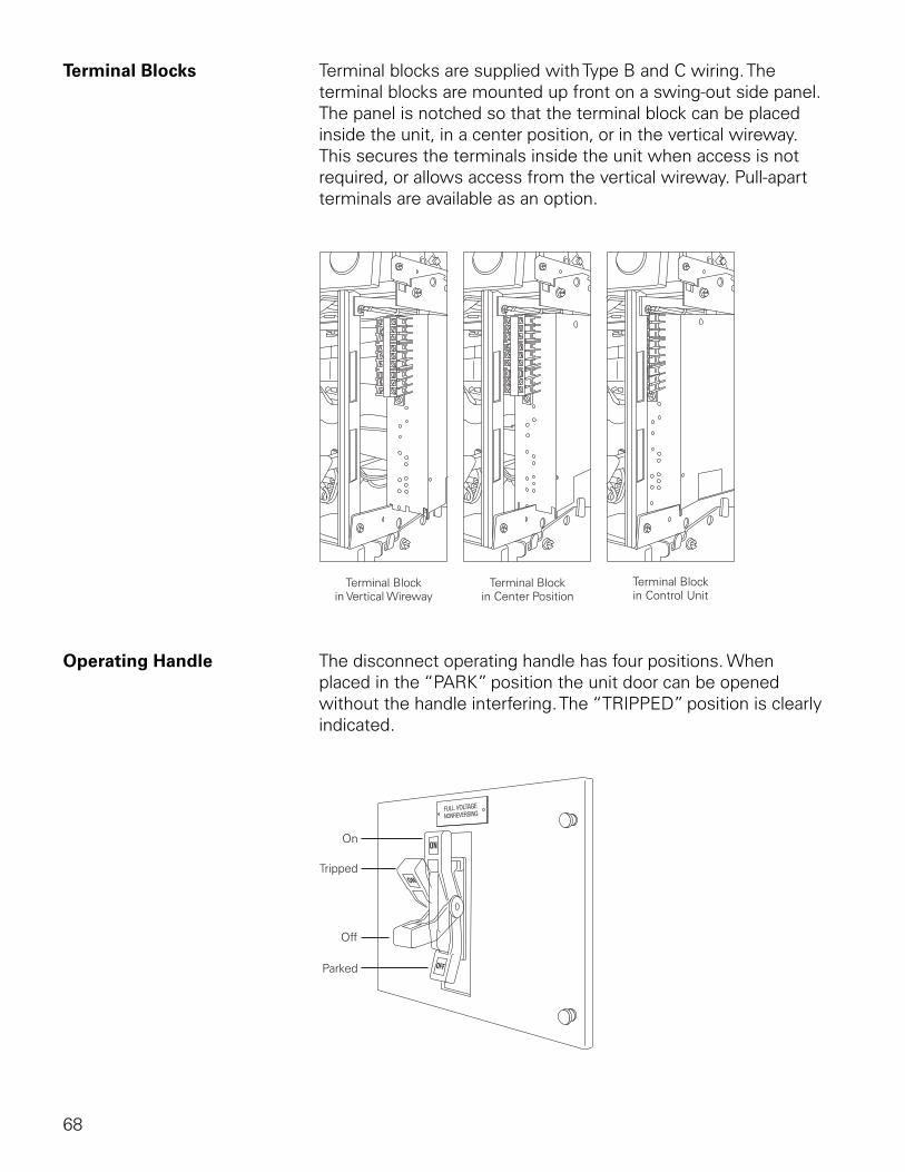
Terminal Blocks Terminal blocks are supplied with Type B and C wiring. The terminal blocks are mounted up front on a swing-out side panel. The panel is notched so that the terminal block can be placed inside the unit, in a center position, or in the vertical wireway. This secures the terminals inside the unit when access is not required, or allows access from the vertical wireway. Pull-apart terminals are available as an option.
Operating Handle The disconnect operating handle has four positions. When placed in the “PARK” position the unit door can be opened without the handle interfering. The “TRIPPED” position is clearly indicated.
69
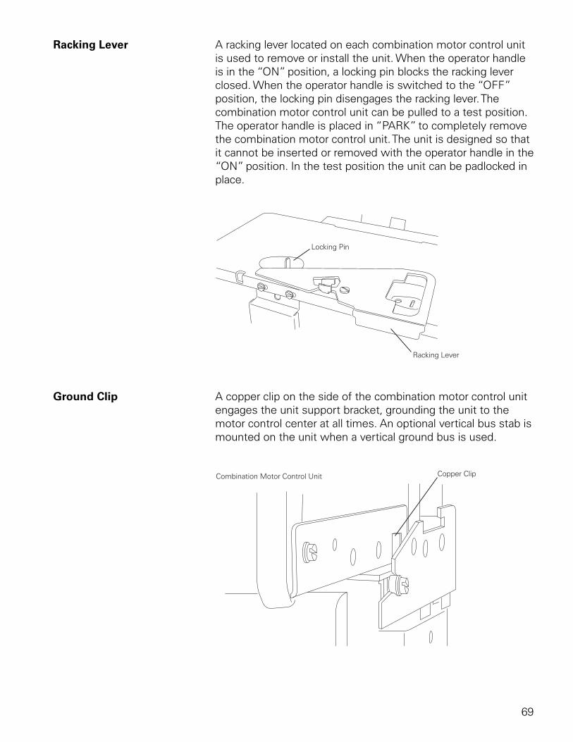
Racking Lever A racking lever located on each combination motor control unit is used to remove or install the unit. When the operator handle is in the “ON” position, a locking pin blocks the racking lever closed. When the operator handle is switched to the “OFF” position, the locking pin disengages the racking lever. The combination motor control unit can be pulled to a test position. The operator handle is placed in “PARK” to completely remove the combination motor control unit. The unit is designed so that it cannot be inserted or removed with the operator handle in the “ON” position. In the test position the unit can be padlocked in place.
Ground Clip A copper clip on the side of the combination motor control unit engages the unit support bracket, grounding the unit to the motor control center at all times. An optional vertical bus stab is mounted on the unit when a vertical ground bus is used.
70
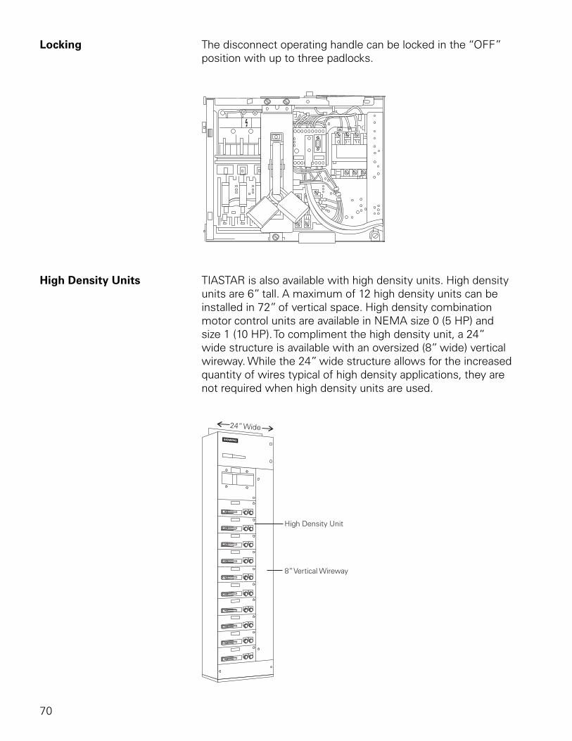
Locking The disconnect operating handle can be locked in the “OFF” position with up to three padlocks.
High Density Units TIASTAR is also available with high density units. High density units are 6” tall. A maximum of 12 high density units can be installed in 72” of vertical space. High density combination motor control units are available in NEMA size 0 (5 HP) and size 1 (10 HP). To compliment the high density unit, a 24” wide structure is available with an oversized (8” wide) vertical wireway. While the 24” wide structure allows for the increased quantity of wires typical of high density applications, they are not required when high density units are used.
71
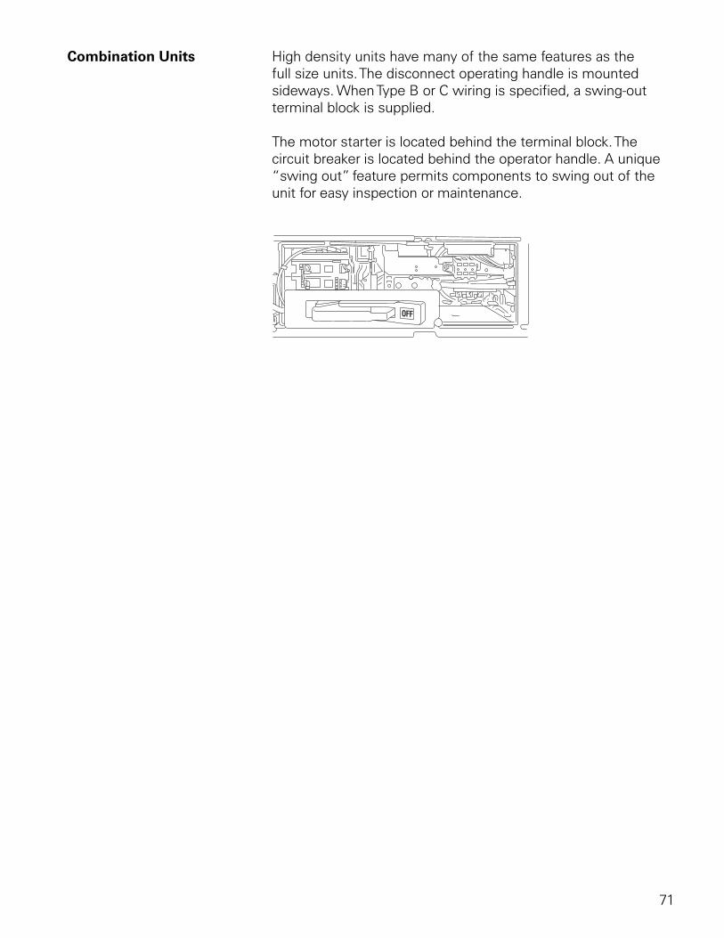
Combination Units High density units have many of the same features as the full size units. The disconnect operating handle is mounted sideways. When Type B or C wiring is specified, a swing-out terminal block is supplied.
The motor starter is located behind the terminal block. The circuit breaker is located behind the operator handle. A unique “swing out” feature permits components to swing out of the unit for easy inspection or maintenance.
72
Information Needed to Order MCCs
When ordering a motor control center several questions need to be answered. The following information will be useful.
• Voltage, frequency, number of phases, and available fault current of power supply
• Incoming power requirements (main circuit breaker, main fusible switch, main lugs only, or splicing to existing MCC)
• Amp rating of the horizontal bus and finish material (tin or silver)
• Voltage rating and source of control power
• Size, type (aluminum or copper), number per phase and location of incoming cables or busway and outgoing cables
• Enclosure - Type, finish - Accessibility (front, rear, or both) - Clearance for door swing - Restrictions on height, width, and depth
• Horsepower rating and motor design of motors to be controlled
• Ampacity of feeder tap units and unit disconnect devices
• Type of disconnect for units: thermal-magnetic, instantaneous trip, or fusible
• Ground bus requirements
• Types of starting method of combination motor-control units, such as FVNR, FVR, 2S1W, 2S2W, PW, or RVAT
• Type of control circuit for units
73
• Service entrance requirements
• Vertical bus requirements (finish, isolated/insulated, amp rating)
• Class and Type of wiring
• Additional equipment requirements (transformers, panelboards, transfer switches, PLCs, etc.)
• Preferred layout of units
• Special features, codes, or restrictions
• Customer specifications
• Drawing requirements
74
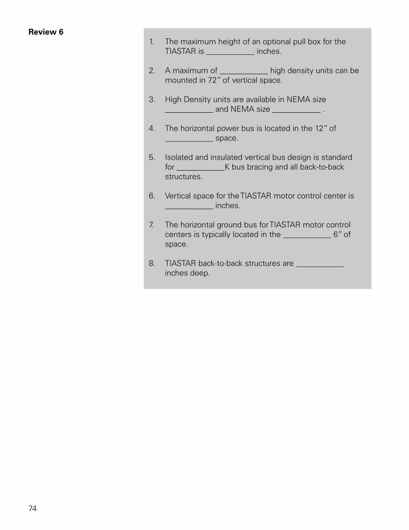
Review 6 1. The maximum height of an optional pull box for the
TIASTAR is ____________ inches.
2. A maximum of ____________ high density units can be mounted in 72” of vertical space.
3. High Density units are available in NEMA size ____________ and NEMA size ____________ .
4. The horizontal power bus is located in the 12” of ____________ space.
5. Isolated and insulated vertical bus design is standard for ____________K bus bracing and all back-to-back structures.
6. Vertical space for the TIASTAR motor control center is ____________ inches.
7. The horizontal ground bus for TIASTAR motor control centers is typically located in the ____________ 6” of space.
8. TIASTAR back-to-back structures are ____________ inches deep.
75
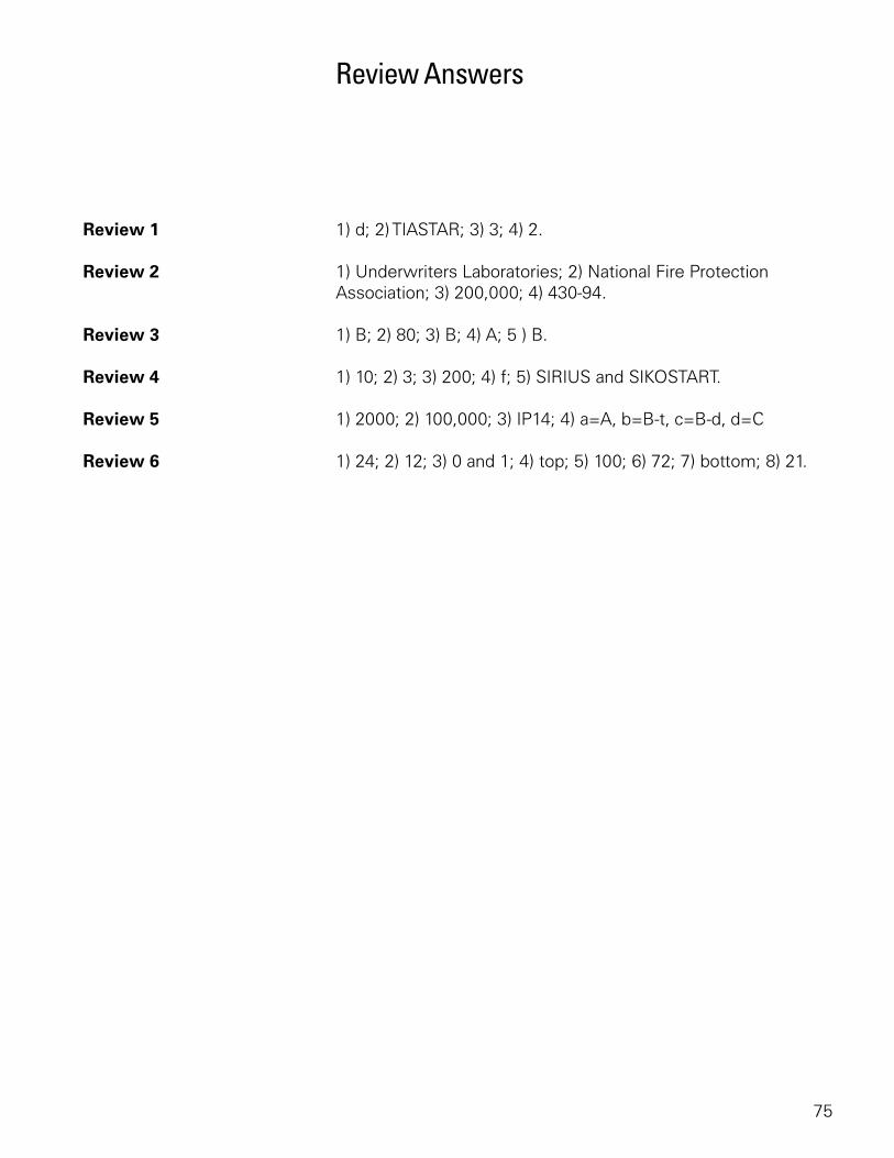
Review Answers
Review 1 1) d; 2) TIASTAR; 3) 3; 4) 2.
Review 2 1) Underwriters Laboratories; 2) National Fire Protection Association; 3) 200,000; 4) 430-94.
Review 3 1) B; 2) 80; 3) B; 4) A; 5 ) B.
Review 4 1) 10; 2) 3; 3) 200; 4) f; 5) SIRIUS and SIKOSTART.
Review 5 1) 2000; 2) 100,000; 3) IP14; 4) a=A, b=B-t, c=B-d, d=C
Review 6 1) 24; 2) 12; 3) 0 and 1; 4) top; 5) 100; 6) 72; 7) bottom; 8) 21.
76
Final Exam
The final exam is intended to be a learning tool. The book may be used during the exam. A tear-out answer sheet is provided. After completing the test, mail the answer sheet in for grading. A grade of 70% or better is passing. Upon successful completion of the test a certificate will be issued.
Questions 1. ____________ is the trade name for a Siemens motor control center.
a. SIKOSTART b. INNOVA PLUS c. SAMMS d. TIASTAR
2. Article ____________ of the National Electrical Code® requires overcurrent protection for MCCs.
a. 430.94 b. 240 c. ICS-1-322 d. 430.97
3. Which of the following is not a part of the NEMA definition for motor control centers?
a. Principally contains branch circuit protection b. Floor-mounted assemblies c. Common horizontal bus d. One or more vertical sections
4. The standard height of a vertical section is ____________ inches.
a. 72 b. 40 c. 90 d. 20
77
5. The maximum shipping width of a motor control center assembly is ____________ inches.
a. 60” b. 80” c. 90” d. 120”
6. According to NEC® Article 430.97, there should be a minimum distance of ____________ inch(es) of clearance between a live bus and ground.
a. 1 b. 2 c. 3 d. 4
7. A Class 20 overload relay will trip within ____________ seconds when motor current is 600%.
a. 3 b. 10 c. 20 d. 30
8. ____________ is a motor protection device that is designed to work with PROFIBUS-DP.
a. INNOVA PLUS b. SENSITRIP III c. FVNR d. SIMOCODE-DP
9. A NEMA size 3 controller is rated for __________ HP at 480 volts.
a. 3 b. 25 c. 50 d. 100
10. Motor control centers are rated for ____________ volts.
a. 480 b. 600 c. 1000 d. 1200
78
11. Up to ____________ 30 mm pilot devices can be mounted on the combination motor control unit door of a Siemens TIASTAR motor control center.
a. 2 b. 4 c. 6 d. 8
12. Siemens motor control centers are manufactured with a maximum temperature rise of ____________ over 40°C ambient.
a. 25°C b. 50°C c. 65°C d. 75°C
13. Type B-t wiring can be used on starters up to size ____________ .
a. 3 b. 5 c. 6 d. 7
14. No terminal blocks are supplied on Class I, Type ____________ wiring.
a. A b. B-t c. B-d d. C
15. Type ____________ wiring is not available on Class II motor control centers.
a. all types are available on Class II b. A c. B d. C
16. The primary standards for MCCs are established by ____________ .
a. ANSI, IEEE, IEC b. ANSI, NEC, IEC c. UL, IEEE, NEMA d. UL, NEMA, NEC®
79
17. TIASTAR high density units take up ____________ inches of vertical space.
a. 18 b. 12 c. 6 d. 4
18. Most Siemens plug-in combination motor control units use ____________ for quick bus connect and disconnect.
a. pull-apart terminal blocks b. two-bolt, U-shaped clamp c. shelf-brackets d. stab clips
19. To remove a combination motor control unit from a System/89 MCC, the operating handle is placed in ____________ .
a. On b. Off c. Park d. Tripped
20. ____________ will allow the use of branch circuit protective units in a motor control center provided their use does not make up a major portion of the motor control center.
a. NEMA (ICS-2-322) b. NEC® (430.97) c. NEC® (430.94) d. UL (845)
80
quickSTEP Online Courses
quickSTEP online courses are available at http://www.sea.siemens.com/step.
The quickSTEP training site is divided into three sections: Courses, Downloads, and a Glossary. Online courses include reviews, a final exam, the ability to print a certificate of completion, and the opportunity to register in the Sales & Distributor training database to maintain a record of your accomplishments.
From this site the complete text of all STEP 2000 courses can be downloaded in PDF format. These files contain the most recent changes and updates to the STEP 2000 courses.
A unique feature of the quickSTEP site is our pictorial glossary. The pictorial glossary can be accessed from anywhere within a quickSTEP course. This enables the student to look up an unfamiliar word without leaving the current work area.
STEP 2000
Basics of PLCs
1
Table of Contents
Introduction ..............................................................................2
PLCs .........................................................................................4
Number Systems......................................................................8
Terminology ............................................................................14
Basic Requirements................................................................23
S7-200 Micro PLCs.................................................................28
Connecting External Devices..................................................39
Programming A PLC ...............................................................41
Discrete Inputs/Outputs .........................................................49
Analog Inputs and Outputs.....................................................61
Timers.....................................................................................64
Counters .................................................................................71
High-Speed Instructions .........................................................75
Specialized Expansion Modules .............................................78
Review Answers.....................................................................84
Final Exam ..............................................................................85
2
Introduction
Welcome to another course in the STEP 2000 series, Siemens Technical Education Program, designed to prepare our distributors to sell Siemens Energy & Automation products more effectively. This course covers Basics of PLCs and related products.
Upon completion of Basics of PLCs you should be able to:
• Identify the major components of a PLC and describe their functions
• Convert numbers from decimal to binary, BCD, and hexadecimal
• Identify typical discrete and analog inputs and outputs
• Read a basic ladder logic diagram and statement list
• Identify operational differences between different S7-200 models
• Identify the proper manual to refer to for programming or installation of an S7-200 PLC
• Connect a simple discrete input and output to an S7-200
• Select the proper expansion module for analog inputs and outputs
• Describe the operation of timers and counters
3
This knowledge will help you better understand customer applications. In addition, you will be better able to describe products to customers and determine important differences between products. You should complete Basics of Electricity before attempting Basics of PLCs. An understanding of many of the concepts covered in Basics of Electricity is required for Basics of PLCs. In addition you may wish to complete Basics of Control Components. Devices covered in Basics of Control Components are used with programmable logic controllers.
If you are an employee of a Siemens Energy & Automation authorized distributor, fill out the final exam tear-out card and mail in the card. We will mail you a certificate of completion if you score a passing grade. Good luck with your efforts.
SIMATIC, STEP 7, STEP 7-Micro, STEP 7-Micro/WIN, PG 702, and PG 740 are registered trademarks of Siemens Energy & Automation, Inc.
Other trademarks are the property of their respective owners.
4
PLCs
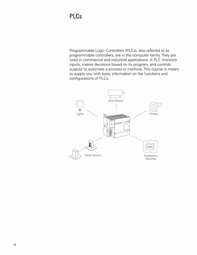
Programmable Logic Controllers (PLCs), also referred to as programmable controllers, are in the computer family. They are used in commercial and industrial applications. A PLC monitors inputs, makes decisions based on its program, and controls outputs to automate a process or machine. This course is meant to supply you with basic information on the functions and configurations of PLCs.
5
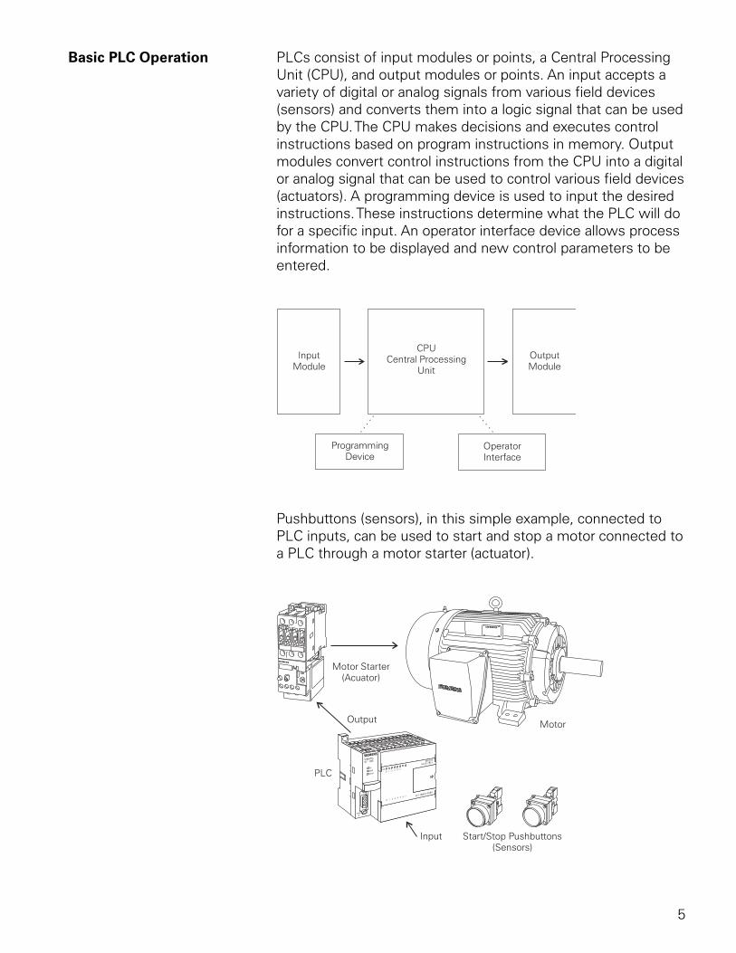
Basic PLC Operation PLCs consist of input modules or points, a Central Processing Unit (CPU), and output modules or points. An input accepts a variety of digital or analog signals from various field devices (sensors) and converts them into a logic signal that can be used by the CPU. The CPU makes decisions and executes control instructions based on program instructions in memory. Output modules convert control instructions from the CPU into a digital or analog signal that can be used to control various field devices (actuators). A programming device is used to input the desired instructions. These instructions determine what the PLC will do for a specific input. An operator interface device allows process information to be displayed and new control parameters to be entered.
Pushbuttons (sensors), in this simple example, connected to PLC inputs, can be used to start and stop a motor connected to a PLC through a motor starter (actuator).
6
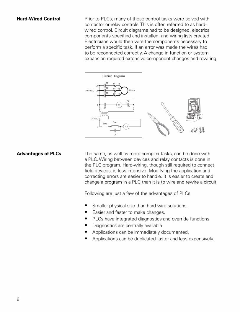
Hard-Wired Control Prior to PLCs, many of these control tasks were solved with contactor or relay controls. This is often referred to as hard-wired control. Circuit diagrams had to be designed, electrical components specified and installed, and wiring lists created. Electricians would then wire the components necessary to perform a specific task. If an error was made the wires had to be reconnected correctly. A change in function or system expansion required extensive component changes and rewiring.
OL
M
CR
CR
L1T1
T2
T3
L2
L3
OL
OL
OL
M
M
CR
MMotor
StartStop
460 VAC
24 VAC
1
2
Advantages of PLCs The same, as well as more complex tasks, can be done with a PLC. Wiring between devices and relay contacts is done in the PLC program. Hard-wiring, though still required to connect field devices, is less intensive. Modifying the application and correcting errors are easier to handle. It is easier to create and change a program in a PLC than it is to wire and rewire a circuit.
Following are just a few of the advantages of PLCs:
• Smaller physical size than hard-wire solutions.• Easier and faster to make changes.• PLCs have integrated diagnostics and override functions.• Diagnostics are centrally available.• Applications can be immediately documented.• Applications can be duplicated faster and less expensively.
7
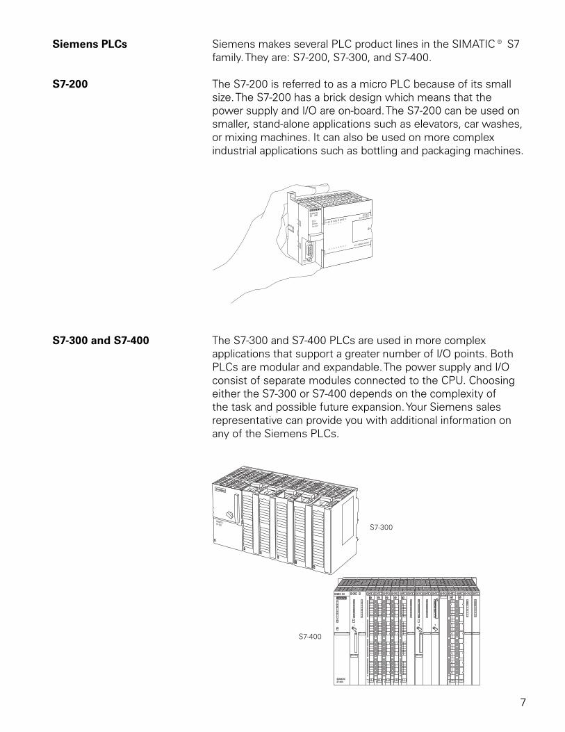
Siemens PLCs Siemens makes several PLC product lines in the SIMATIC® S7 family. They are: S7-200, S7-300, and S7-400.
S7-200 The S7-200 is referred to as a micro PLC because of its small size. The S7-200 has a brick design which means that the power supply and I/O are on-board. The S7-200 can be used on smaller, stand-alone applications such as elevators, car washes, or mixing machines. It can also be used on more complex industrial applications such as bottling and packaging machines.
S7-300 and S7-400 The S7-300 and S7-400 PLCs are used in more complex applications that support a greater number of I/O points. Both PLCs are modular and expandable. The power supply and I/O consist of separate modules connected to the CPU. Choosing either the S7-300 or S7-400 depends on the complexity of the task and possible future expansion. Your Siemens sales representative can provide you with additional information on any of the Siemens PLCs.
8
Number Systems
Since a PLC is a computer, it stores information in the form of On or Off conditions (1 or 0), referred to as binary digits (bits). Sometimes binary digits are used individually and sometimes they are used to represent numerical values.
Decimal System Various number systems are used by PLCs. All number systems have the same three characteristics: digits, base, weight. The decimal system, which is commonly used in everyday life, has the following characteristics:
Ten digits 0, 1, 2, 3, 4, 5, 6, 7, 8, 9Base 10Weights 1, 10, 100, 1000, ...
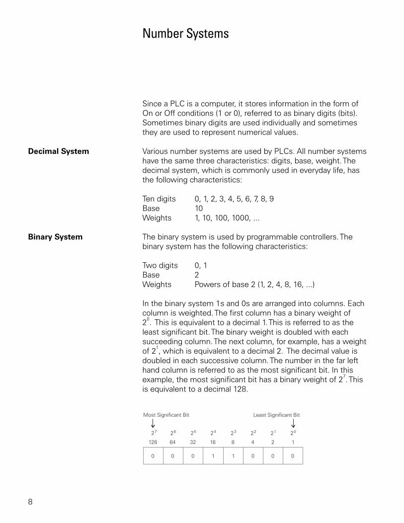
Binary System The binary system is used by programmable controllers. The binary system has the following characteristics:
Two digits 0, 1Base 2Weights Powers of base 2 (1, 2, 4, 8, 16, ...)
In the binary system 1s and 0s are arranged into columns. Each column is weighted. The first column has a binary weight of 2
0. This is equivalent to a decimal 1. This is referred to as the
least significant bit. The binary weight is doubled with each succeeding column. The next column, for example, has a weight of 2
1, which is equivalent to a decimal 2. The decimal value is
doubled in each successive column. The number in the far left hand column is referred to as the most significant bit. In this example, the most significant bit has a binary weight of 2
7. This
is equivalent to a decimal 128.
9
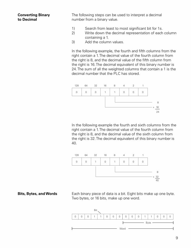
Converting Binary The following steps can be used to interpret a decimal to Decimal number from a binary value.
1) Search from least to most significant bit for 1s.2) Write down the decimal representation of each column
containing a 1.3) Add the column values.
In the following example, the fourth and fifth columns from the right contain a 1. The decimal value of the fourth column from the right is 8, and the decimal value of the fifth column from the right is 16. The decimal equivalent of this binary number is 24. The sum of all the weighted columns that contain a 1 is the decimal number that the PLC has stored.
In the following example the fourth and sixth columns from the right contain a 1. The decimal value of the fourth column from the right is 8, and the decimal value of the sixth column from the right is 32. The decimal equivalent of this binary number is 40.
Bits, Bytes, and Words Each binary piece of data is a bit. Eight bits make up one byte. Two bytes, or 16 bits, make up one word.
10
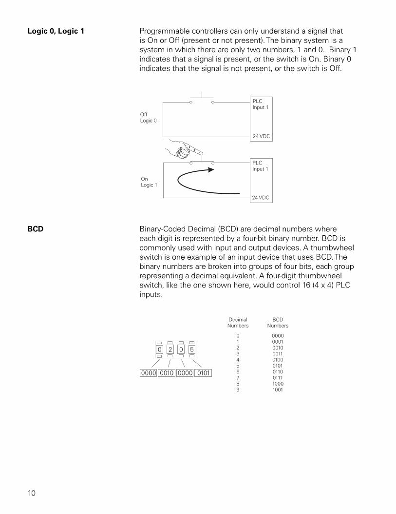
Logic 0, Logic 1 Programmable controllers can only understand a signal that is On or Off (present or not present). The binary system is a system in which there are only two numbers, 1 and 0. Binary 1 indicates that a signal is present, or the switch is On. Binary 0 indicates that the signal is not present, or the switch is Off.
BCD Binary-Coded Decimal (BCD) are decimal numbers where each digit is represented by a four-bit binary number. BCD is commonly used with input and output devices. A thumbwheel switch is one example of an input device that uses BCD. The binary numbers are broken into groups of four bits, each group representing a decimal equivalent. A four-digit thumbwheel switch, like the one shown here, would control 16 (4 x 4) PLC inputs.
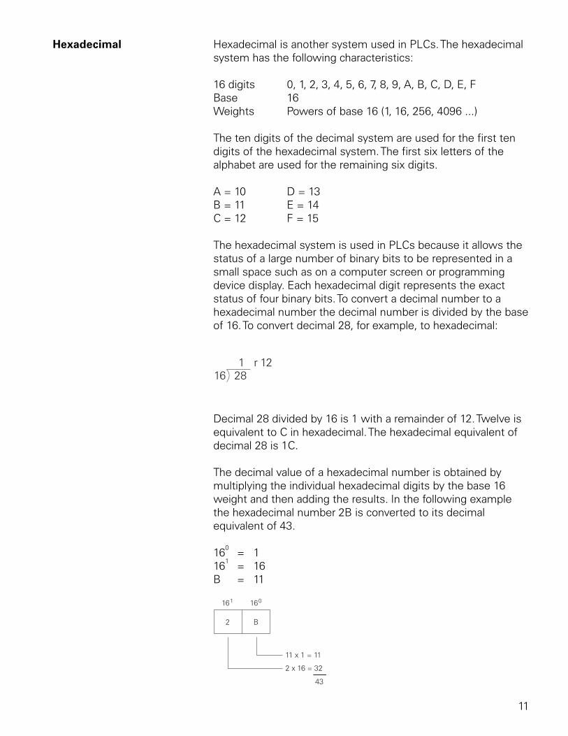
11
Hexadecimal Hexadecimal is another system used in PLCs. The hexadecimal system has the following characteristics:
16 digits 0, 1, 2, 3, 4, 5, 6, 7, 8, 9, A, B, C, D, E, FBase 16Weights Powers of base 16 (1, 16, 256, 4096 ...)
The ten digits of the decimal system are used for the first ten digits of the hexadecimal system. The first six letters of the alphabet are used for the remaining six digits.
A = 10 D = 13B = 11 E = 14C = 12 F = 15
The hexadecimal system is used in PLCs because it allows the status of a large number of binary bits to be represented in a small space such as on a computer screen or programming device display. Each hexadecimal digit represents the exact status of four binary bits. To convert a decimal number to a hexadecimal number the decimal number is divided by the base of 16. To convert decimal 28, for example, to hexadecimal:
Decimal 28 divided by 16 is 1 with a remainder of 12. Twelve is equivalent to C in hexadecimal. The hexadecimal equivalent of decimal 28 is 1C.
The decimal value of a hexadecimal number is obtained by multiplying the individual hexadecimal digits by the base 16 weight and then adding the results. In the following example the hexadecimal number 2B is converted to its decimal equivalent of 43.
160 = 1
161 = 16
B = 11
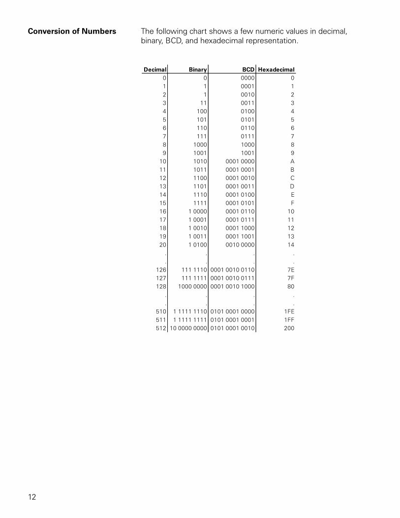
12
Conversion of Numbers The following chart shows a few numeric values in decimal, binary, BCD, and hexadecimal representation.
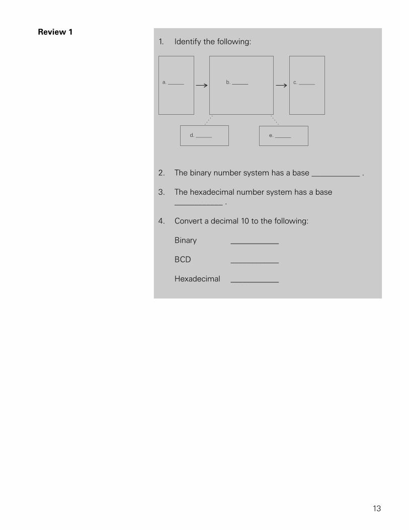
13
Review 1 1. Identify the following:
2. The binary number system has a base ____________ .
3. The hexadecimal number system has a base ____________ .
4. Convert a decimal 10 to the following:
Binary ____________
BCD ____________
Hexadecimal ____________
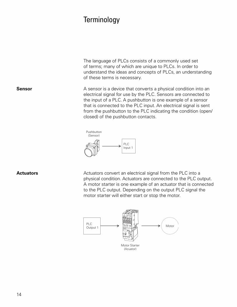
14
Terminology
The language of PLCs consists of a commonly used set of terms; many of which are unique to PLCs. In order to understand the ideas and concepts of PLCs, an understanding of these terms is necessary.
Sensor A sensor is a device that converts a physical condition into an electrical signal for use by the PLC. Sensors are connected to the input of a PLC. A pushbutton is one example of a sensor that is connected to the PLC input. An electrical signal is sent from the pushbutton to the PLC indicating the condition (open/closed) of the pushbutton contacts.
Actuators Actuators convert an electrical signal from the PLC into a physical condition. Actuators are connected to the PLC output. A motor starter is one example of an actuator that is connected to the PLC output. Depending on the output PLC signal the motor starter will either start or stop the motor.
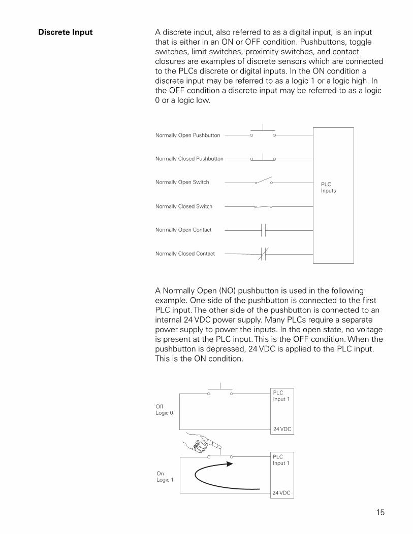
15
Discrete Input A discrete input, also referred to as a digital input, is an input that is either in an ON or OFF condition. Pushbuttons, toggle switches, limit switches, proximity switches, and contact closures are examples of discrete sensors which are connected to the PLCs discrete or digital inputs. In the ON condition a discrete input may be referred to as a logic 1 or a logic high. In the OFF condition a discrete input may be referred to as a logic 0 or a logic low.
A Normally Open (NO) pushbutton is used in the following example. One side of the pushbutton is connected to the first PLC input. The other side of the pushbutton is connected to an internal 24 VDC power supply. Many PLCs require a separate power supply to power the inputs. In the open state, no voltage is present at the PLC input. This is the OFF condition. When the pushbutton is depressed, 24 VDC is applied to the PLC input. This is the ON condition.
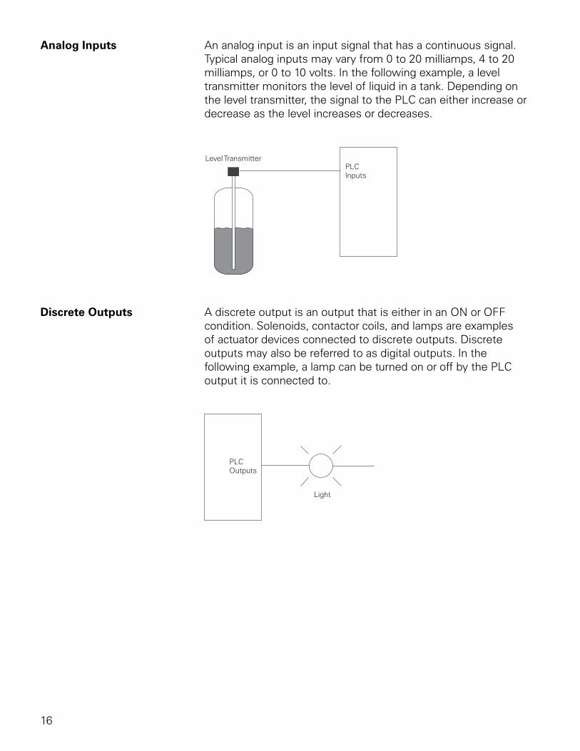
16
Analog Inputs An analog input is an input signal that has a continuous signal. Typical analog inputs may vary from 0 to 20 milliamps, 4 to 20 milliamps, or 0 to 10 volts. In the following example, a level transmitter monitors the level of liquid in a tank. Depending on the level transmitter, the signal to the PLC can either increase or decrease as the level increases or decreases.
Discrete Outputs A discrete output is an output that is either in an ON or OFF condition. Solenoids, contactor coils, and lamps are examples of actuator devices connected to discrete outputs. Discrete outputs may also be referred to as digital outputs. In the following example, a lamp can be turned on or off by the PLC output it is connected to.
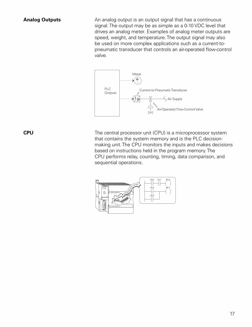
17
Analog Outputs An analog output is an output signal that has a continuous signal. The output may be as simple as a 0-10 VDC level that drives an analog meter. Examples of analog meter outputs are speed, weight, and temperature. The output signal may also be used on more complex applications such as a current-to-pneumatic transducer that controls an air-operated flow-control valve.
CPU The central processor unit (CPU) is a microprocessor system that contains the system memory and is the PLC decision-making unit. The CPU monitors the inputs and makes decisions based on instructions held in the program memory. The CPU performs relay, counting, timing, data comparison, and sequential operations.
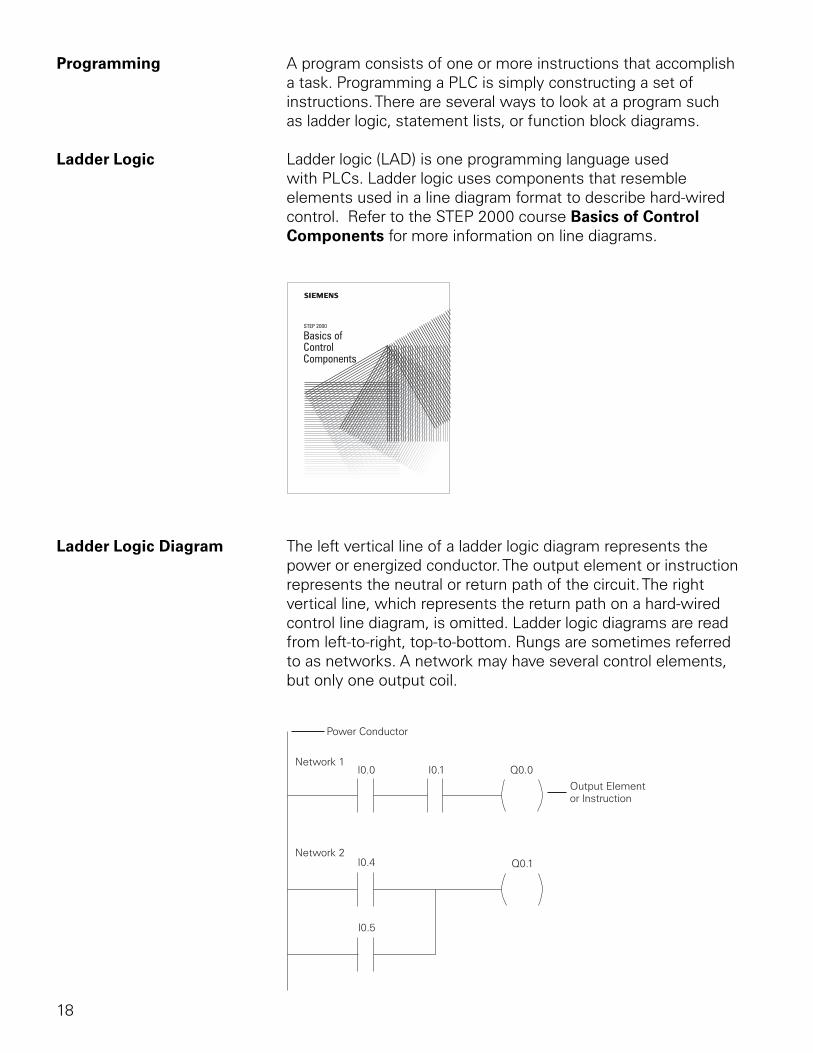
18
Programming A program consists of one or more instructions that accomplish a task. Programming a PLC is simply constructing a set of instructions. There are several ways to look at a program such as ladder logic, statement lists, or function block diagrams.
Ladder Logic Ladder logic (LAD) is one programming language used with PLCs. Ladder logic uses components that resemble elements used in a line diagram format to describe hard-wired control. Refer to the STEP 2000 course Basics of Control Components for more information on line diagrams.
STEP 2000
Basics ofControlComponents
Ladder Logic Diagram The left vertical line of a ladder logic diagram represents the power or energized conductor. The output element or instruction represents the neutral or return path of the circuit. The right vertical line, which represents the return path on a hard-wired control line diagram, is omitted. Ladder logic diagrams are read from left-to-right, top-to-bottom. Rungs are sometimes referred to as networks. A network may have several control elements, but only one output coil.
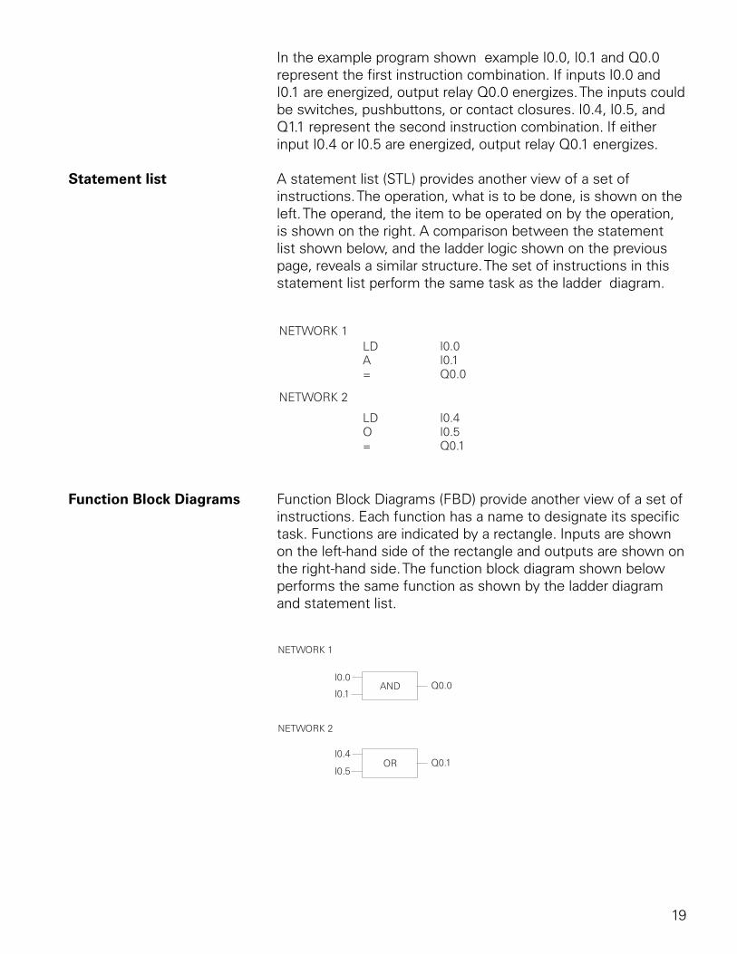
19
In the example program shown example I0.0, I0.1 and Q0.0 represent the first instruction combination. If inputs I0.0 and I0.1 are energized, output relay Q0.0 energizes. The inputs could be switches, pushbuttons, or contact closures. I0.4, I0.5, and Q1.1 represent the second instruction combination. If either input I0.4 or I0.5 are energized, output relay Q0.1 energizes.
Statement list A statement list (STL) provides another view of a set of instructions. The operation, what is to be done, is shown on the left. The operand, the item to be operated on by the operation, is shown on the right. A comparison between the statement list shown below, and the ladder logic shown on the previous page, reveals a similar structure. The set of instructions in this statement list perform the same task as the ladder diagram.
Function Block Diagrams Function Block Diagrams (FBD) provide another view of a set of instructions. Each function has a name to designate its specific task. Functions are indicated by a rectangle. Inputs are shown on the left-hand side of the rectangle and outputs are shown on the right-hand side. The function block diagram shown below performs the same function as shown by the ladder diagram and statement list.
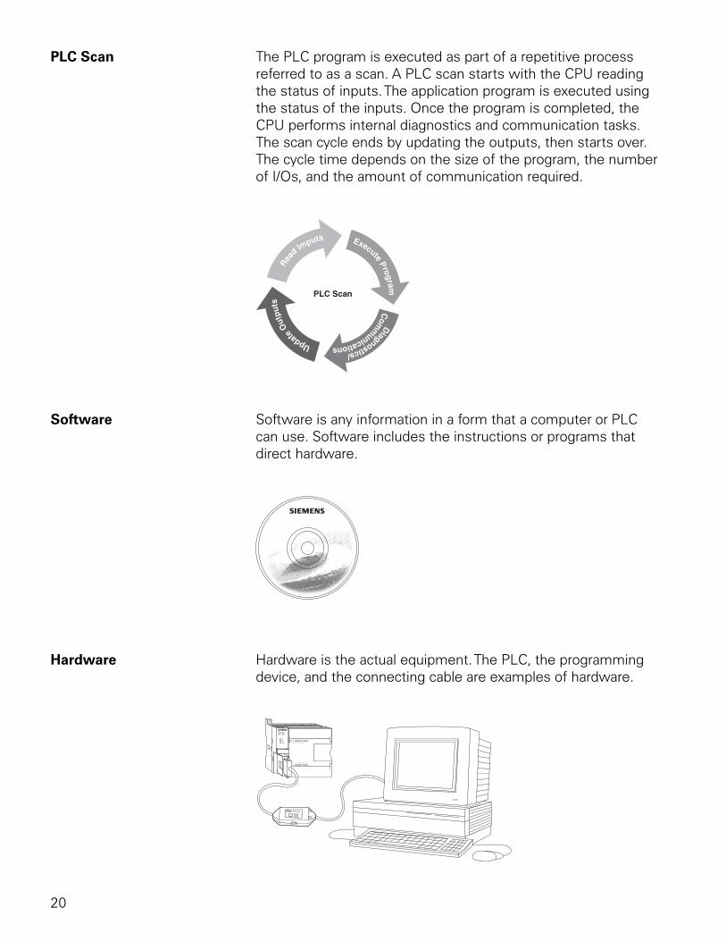
20
PLC Scan The PLC program is executed as part of a repetitive process referred to as a scan. A PLC scan starts with the CPU reading the status of inputs. The application program is executed using the status of the inputs. Once the program is completed, the CPU performs internal diagnostics and communication tasks. The scan cycle ends by updating the outputs, then starts over. The cycle time depends on the size of the program, the number of I/Os, and the amount of communication required.
Software Software is any information in a form that a computer or PLC can use. Software includes the instructions or programs that direct hardware.
Hardware Hardware is the actual equipment. The PLC, the programming device, and the connecting cable are examples of hardware.
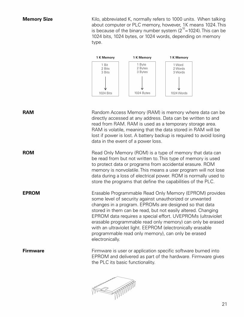
21
Memory Size Kilo, abbreviated K, normally refers to 1000 units. When talking about computer or PLC memory, however, 1K means 1024. This is because of the binary number system (2
10=1024). This can be
1024 bits, 1024 bytes, or 1024 words, depending on memory type.
RAM Random Access Memory (RAM) is memory where data can be directly accessed at any address. Data can be written to and read from RAM. RAM is used as a temporary storage area. RAM is volatile, meaning that the data stored in RAM will be lost if power is lost. A battery backup is required to avoid losing data in the event of a power loss.
ROM Read Only Memory (ROM) is a type of memory that data can be read from but not written to. This type of memory is used to protect data or programs from accidental erasure. ROM memory is nonvolatile. This means a user program will not lose data during a loss of electrical power. ROM is normally used to store the programs that define the capabilities of the PLC.
EPROM Erasable Programmable Read Only Memory (EPROM) provides some level of security against unauthorized or unwanted changes in a program. EPROMs are designed so that data stored in them can be read, but not easily altered. Changing EPROM data requires a special effort. UVEPROMs (ultraviolet erasable programmable read only memory) can only be erased with an ultraviolet light. EEPROM (electronically erasable programmable read only memory), can only be erased electronically.
Firmware Firmware is user or application specific software burned into EPROM and delivered as part of the hardware. Firmware gives the PLC its basic functionality.
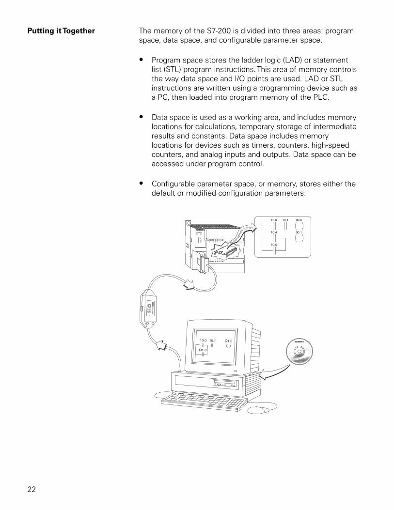
22
Putting it Together The memory of the S7-200 is divided into three areas: program space, data space, and configurable parameter space.
• Program space stores the ladder logic (LAD) or statement list (STL) program instructions. This area of memory controls the way data space and I/O points are used. LAD or STL instructions are written using a programming device such as a PC, then loaded into program memory of the PLC.
• Data space is used as a working area, and includes memory locations for calculations, temporary storage of intermediate results and constants. Data space includes memory locations for devices such as timers, counters, high-speed counters, and analog inputs and outputs. Data space can be accessed under program control.
• Configurable parameter space, or memory, stores either the default or modified configuration parameters.
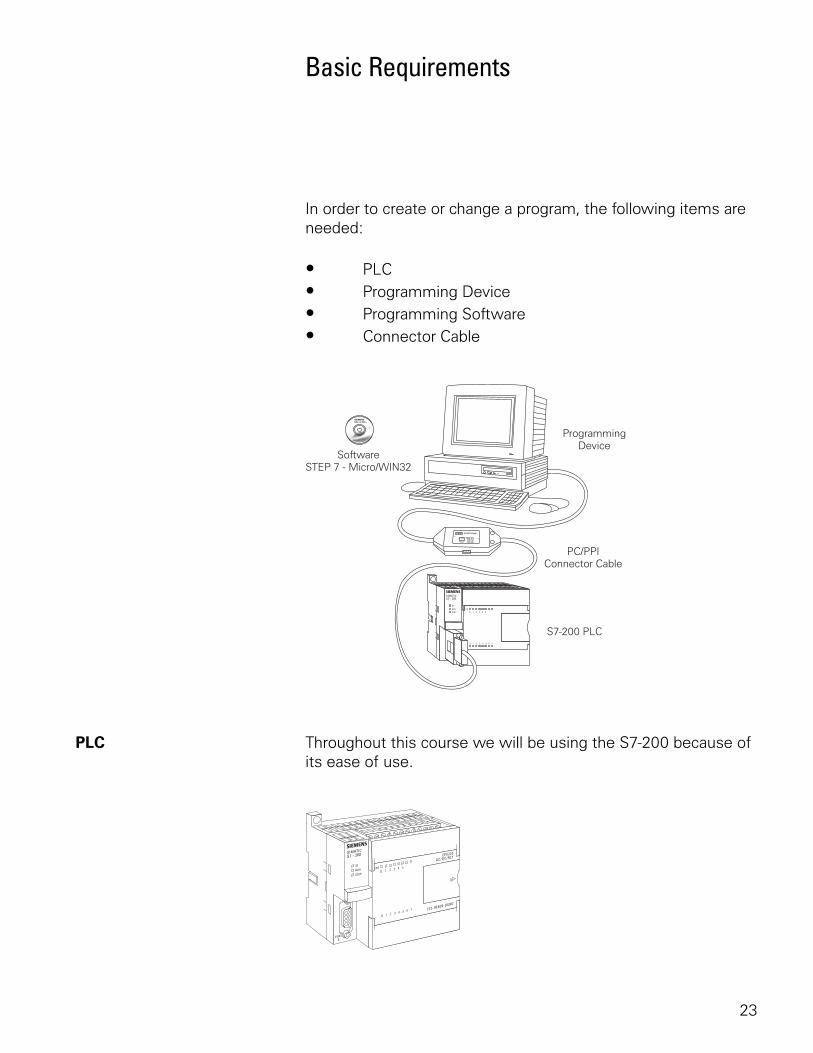
23
Basic Requirements
In order to create or change a program, the following items are needed:
• PLC• Programming Device• Programming Software• Connector Cable
PLC Throughout this course we will be using the S7-200 because of its ease of use.
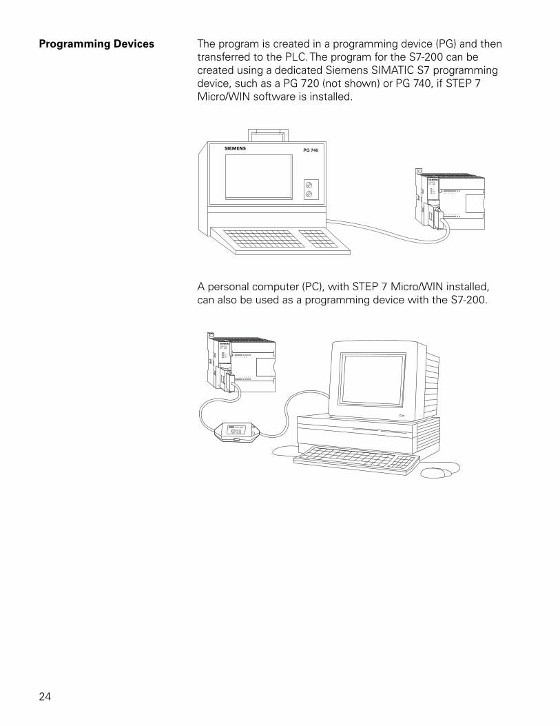
24
Programming Devices The program is created in a programming device (PG) and then transferred to the PLC. The program for the S7-200 can be created using a dedicated Siemens SIMATIC S7 programming device, such as a PG 720 (not shown) or PG 740, if STEP 7 Micro/WIN software is installed.
A personal computer (PC), with STEP 7 Micro/WIN installed, can also be used as a programming device with the S7-200.
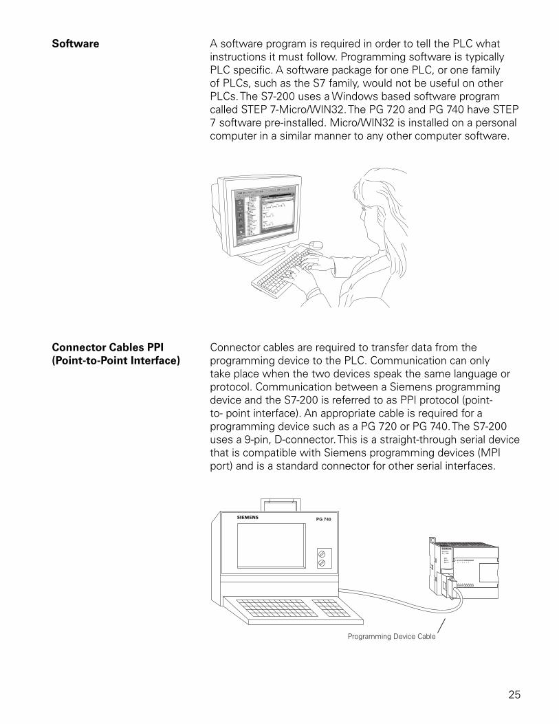
25
Software A software program is required in order to tell the PLC what instructions it must follow. Programming software is typically PLC specific. A software package for one PLC, or one family of PLCs, such as the S7 family, would not be useful on other PLCs. The S7-200 uses a Windows based software program called STEP 7-Micro/WIN32. The PG 720 and PG 740 have STEP 7 software pre-installed. Micro/WIN32 is installed on a personal computer in a similar manner to any other computer software.
Connector Cables PPI Connector cables are required to transfer data from the (Point-to-Point Interface) programming device to the PLC. Communication can only
take place when the two devices speak the same language or protocol. Communication between a Siemens programming device and the S7-200 is referred to as PPI protocol (point-to- point interface). An appropriate cable is required for a programming device such as a PG 720 or PG 740. The S7-200 uses a 9-pin, D-connector. This is a straight-through serial device that is compatible with Siemens programming devices (MPI port) and is a standard connector for other serial interfaces.
Programming Device Cable
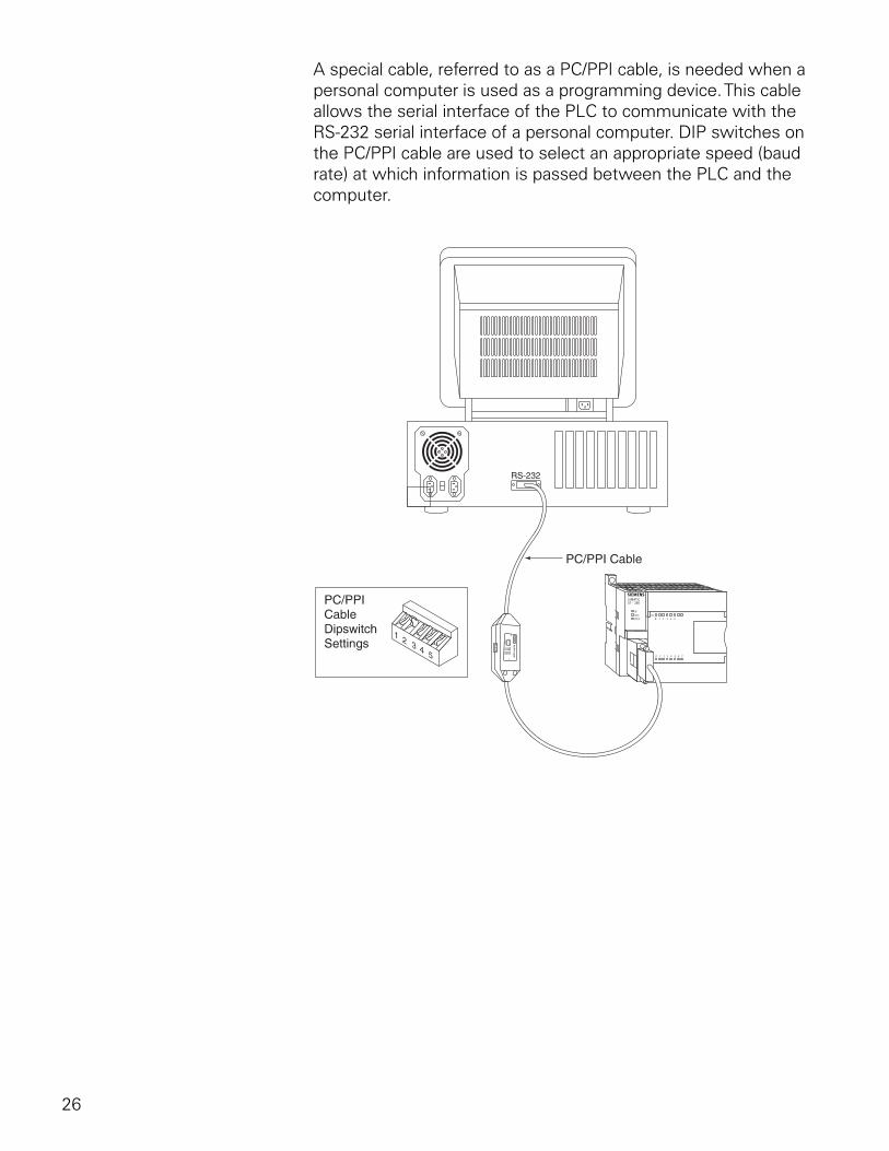
26
A special cable, referred to as a PC/PPI cable, is needed when a personal computer is used as a programming device. This cable allows the serial interface of the PLC to communicate with the RS-232 serial interface of a personal computer. DIP switches on the PC/PPI cable are used to select an appropriate speed (baud rate) at which information is passed between the PLC and the computer.
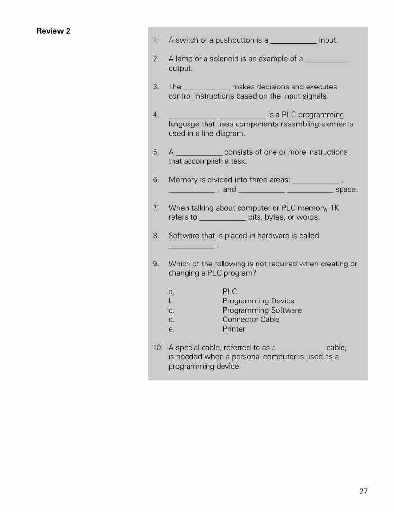
27
Review 2 1. A switch or a pushbutton is a ____________ input.
2. A lamp or a solenoid is an example of a ___________ output.
3. The ____________ makes decisions and executes control instructions based on the input signals.
4. ____________ ____________ is a PLC programming language that uses components resembling elements used in a line diagram.
5. A ____________ consists of one or more instructions that accomplish a task.
6. Memory is divided into three areas: ____________ , ____________ , and ____________ ____________ space.
7. When talking about computer or PLC memory, 1K refers to ____________ bits, bytes, or words.
8. Software that is placed in hardware is called ____________ .
9. Which of the following is not required when creating or changing a PLC program?
a. PLC b. Programming Device c. Programming Software d. Connector Cable e. Printer
10. A special cable, referred to as a ____________ cable, is needed when a personal computer is used as a programming device.
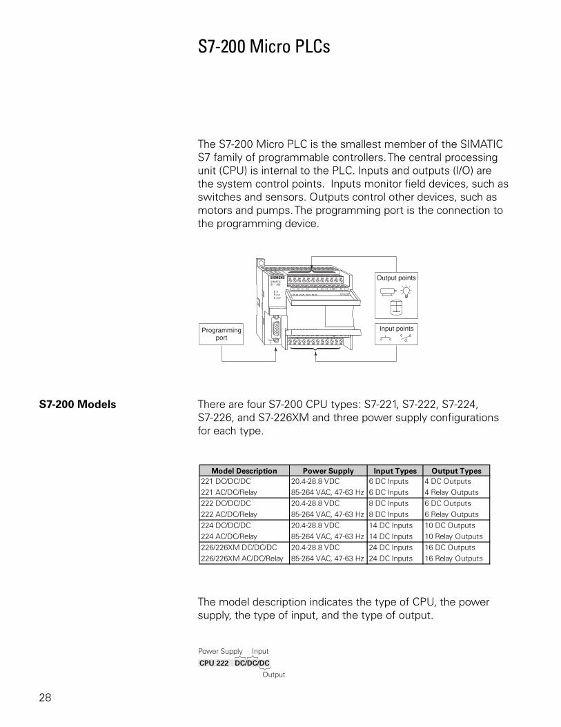
28
S7-200 Micro PLCs
The S7-200 Micro PLC is the smallest member of the SIMATIC S7 family of programmable controllers. The central processing unit (CPU) is internal to the PLC. Inputs and outputs (I/O) are the system control points. Inputs monitor field devices, such as switches and sensors. Outputs control other devices, such as motors and pumps. The programming port is the connection to the programming device.
S7-200 Models There are four S7-200 CPU types: S7-221, S7-222, S7-224, S7-226, and S7-226XM and three power supply configurations for each type.
The model description indicates the type of CPU, the power supply, the type of input, and the type of output.
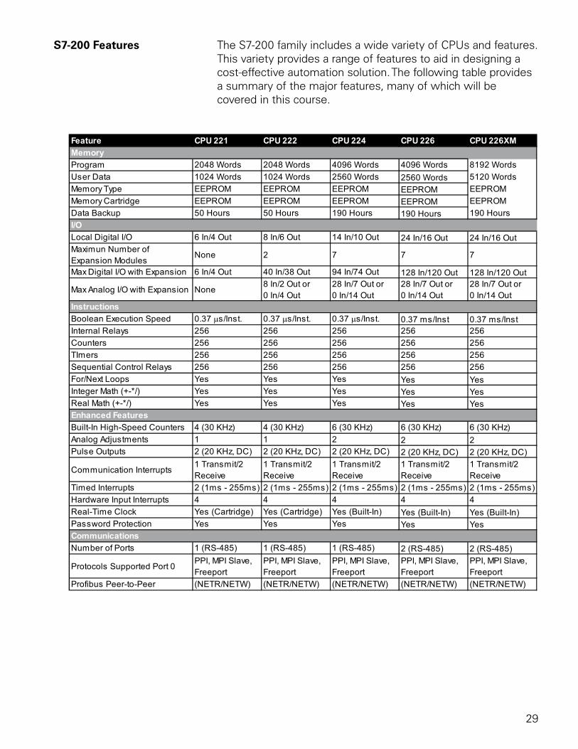
29
S7-200 Features The S7-200 family includes a wide variety of CPUs and features. This variety provides a range of features to aid in designing a cost-effective automation solution. The following table provides a summary of the major features, many of which will be covered in this course.
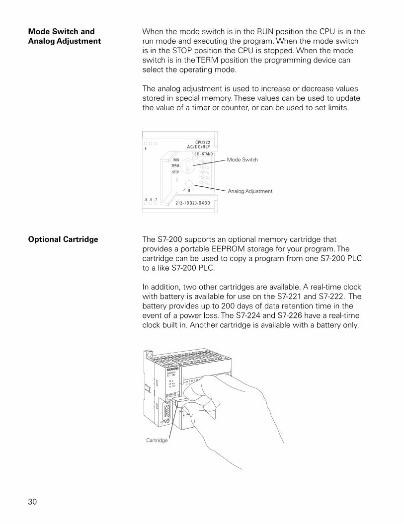
30
Mode Switch and When the mode switch is in the RUN position the CPU is in theAnalog Adjustment run mode and executing the program. When the mode switch
is in the STOP position the CPU is stopped. When the mode switch is in the TERM position the programming device can select the operating mode.
The analog adjustment is used to increase or decrease values stored in special memory. These values can be used to update the value of a timer or counter, or can be used to set limits.
Optional Cartridge The S7-200 supports an optional memory cartridge that provides a portable EEPROM storage for your program. The cartridge can be used to copy a program from one S7-200 PLC to a like S7-200 PLC.
In addition, two other cartridges are available. A real-time clock with battery is available for use on the S7-221 and S7-222. The battery provides up to 200 days of data retention time in the event of a power loss. The S7-224 and S7-226 have a real-time clock built in. Another cartridge is available with a battery only.
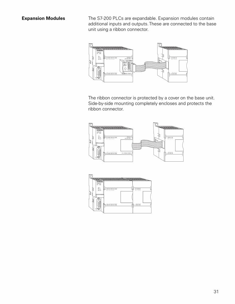
31
Expansion Modules The S7-200 PLCs are expandable. Expansion modules contain additional inputs and outputs. These are connected to the base unit using a ribbon connector.
The ribbon connector is protected by a cover on the base unit. Side-by-side mounting completely encloses and protects the ribbon connector.
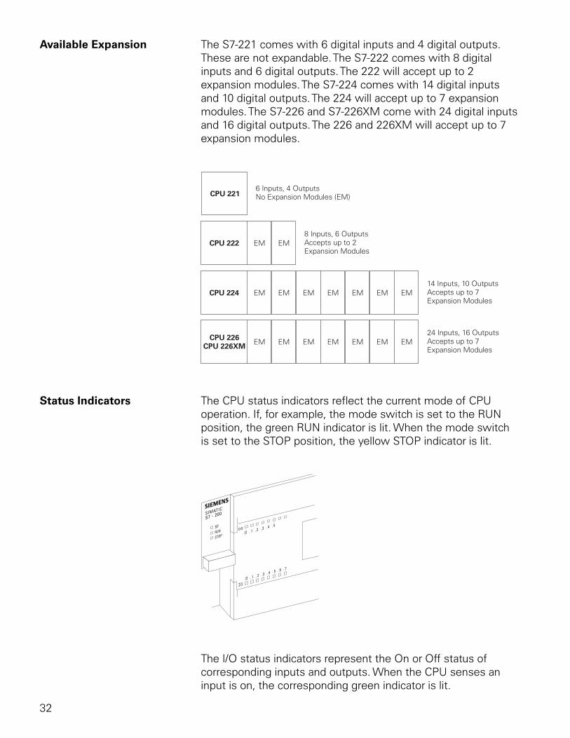
32
Available Expansion The S7-221 comes with 6 digital inputs and 4 digital outputs. These are not expandable. The S7-222 comes with 8 digital inputs and 6 digital outputs. The 222 will accept up to 2 expansion modules. The S7-224 comes with 14 digital inputs and 10 digital outputs. The 224 will accept up to 7 expansion modules. The S7-226 and S7-226XM come with 24 digital inputs and 16 digital outputs. The 226 and 226XM will accept up to 7 expansion modules.
Status Indicators The CPU status indicators reflect the current mode of CPU operation. If, for example, the mode switch is set to the RUN position, the green RUN indicator is lit. When the mode switch is set to the STOP position, the yellow STOP indicator is lit.
The I/O status indicators represent the On or Off status of corresponding inputs and outputs. When the CPU senses an input is on, the corresponding green indicator is lit.
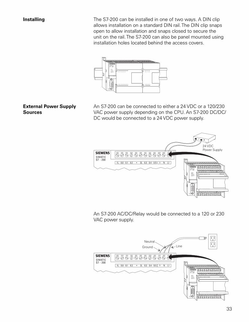
33
Installing The S7-200 can be installed in one of two ways. A DIN clip allows installation on a standard DIN rail. The DIN clip snaps open to allow installation and snaps closed to secure the unit on the rail. The S7-200 can also be panel mounted using installation holes located behind the access covers.
External Power Supply An S7-200 can be connected to either a 24 VDC or a 120/230Sources VAC power supply depending on the CPU. An S7-200 DC/DC/
DC would be connected to a 24 VDC power supply.
An S7-200 AC/DC/Relay would be connected to a 120 or 230 VAC power supply.
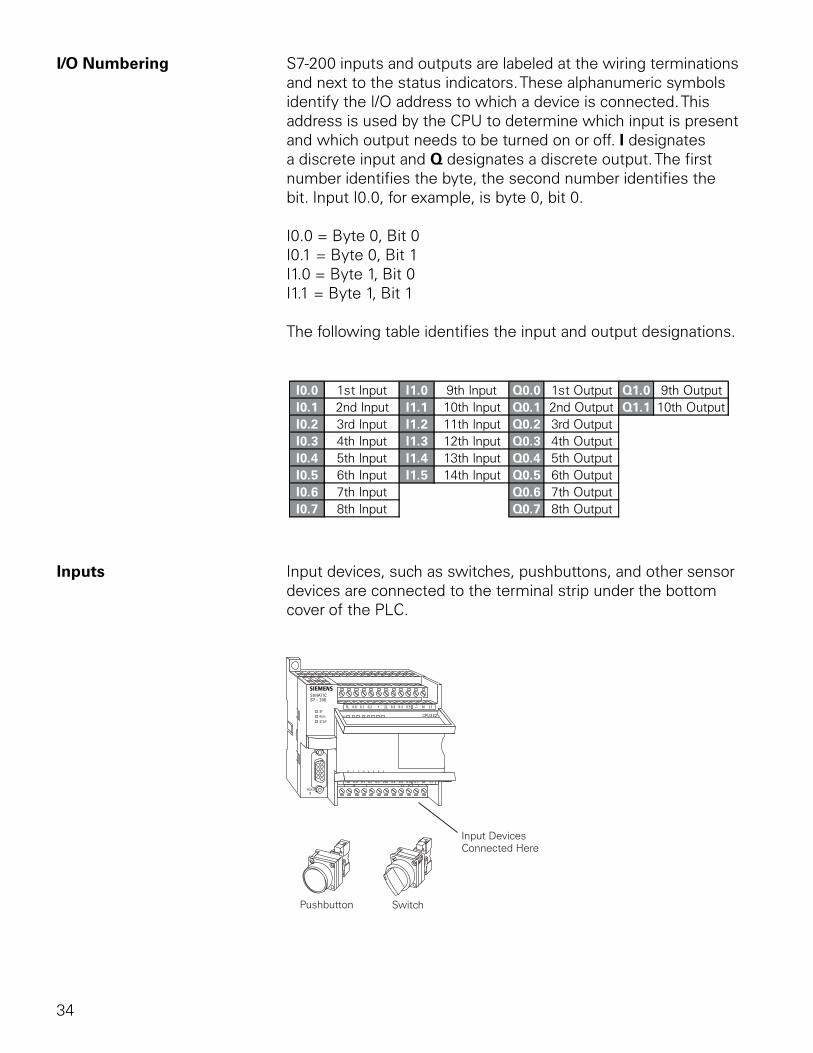
34
I/O Numbering S7-200 inputs and outputs are labeled at the wiring terminations and next to the status indicators. These alphanumeric symbols identify the I/O address to which a device is connected. This address is used by the CPU to determine which input is present and which output needs to be turned on or off. I designates a discrete input and Q designates a discrete output. The first number identifies the byte, the second number identifies the bit. Input I0.0, for example, is byte 0, bit 0.
I0.0 = Byte 0, Bit 0I0.1 = Byte 0, Bit 1I1.0 = Byte 1, Bit 0I1.1 = Byte 1, Bit 1
The following table identifies the input and output designations.
Inputs Input devices, such as switches, pushbuttons, and other sensor devices are connected to the terminal strip under the bottom cover of the PLC.
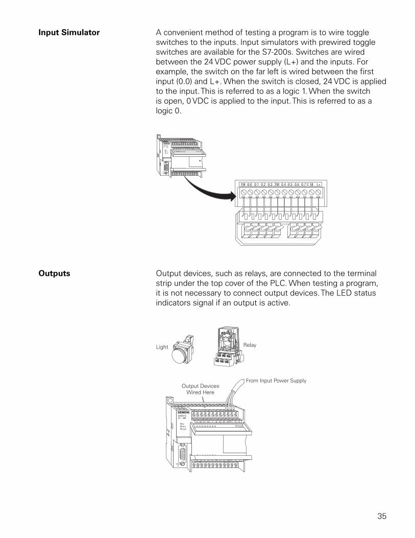
35
Input Simulator A convenient method of testing a program is to wire toggle switches to the inputs. Input simulators with prewired toggle switches are available for the S7-200s. Switches are wired between the 24 VDC power supply (L+) and the inputs. For example, the switch on the far left is wired between the first input (0.0) and L+. When the switch is closed, 24 VDC is applied to the input. This is referred to as a logic 1. When the switch is open, 0 VDC is applied to the input. This is referred to as a logic 0.
Outputs Output devices, such as relays, are connected to the terminal strip under the top cover of the PLC. When testing a program, it is not necessary to connect output devices. The LED status indicators signal if an output is active.
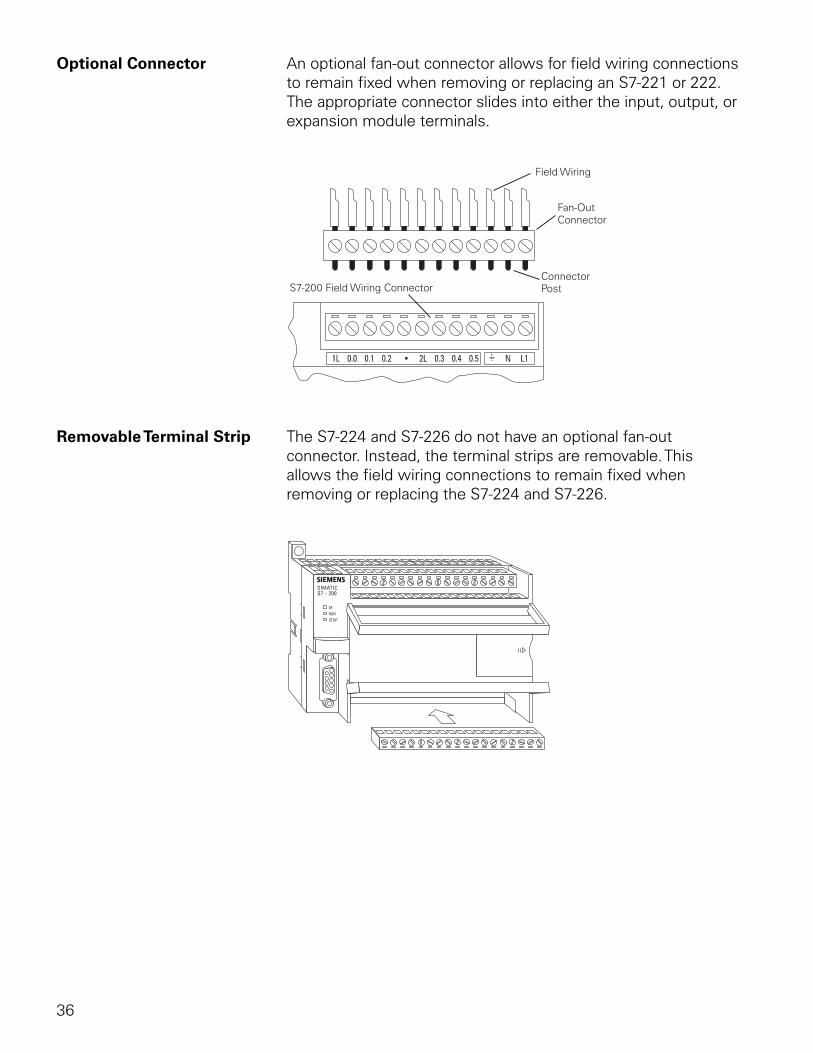
36
Optional Connector An optional fan-out connector allows for field wiring connections to remain fixed when removing or replacing an S7-221 or 222. The appropriate connector slides into either the input, output, or expansion module terminals.
Removable Terminal Strip The S7-224 and S7-226 do not have an optional fan-out connector. Instead, the terminal strips are removable. This allows the field wiring connections to remain fixed when removing or replacing the S7-224 and S7-226.
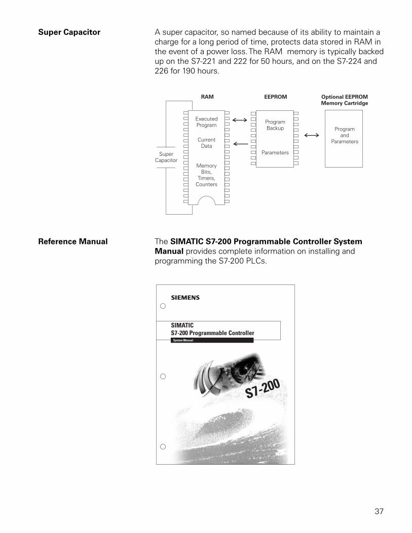
37
Super Capacitor A super capacitor, so named because of its ability to maintain a charge for a long period of time, protects data stored in RAM in the event of a power loss. The RAM memory is typically backed up on the S7-221 and 222 for 50 hours, and on the S7-224 and 226 for 190 hours.
Reference Manual The SIMATIC S7-200 Programmable Controller System Manual provides complete information on installing and programming the S7-200 PLCs.
38
Review 31. The five models of S7-200 are ____________ ,
____________ , ____________ , ____________, and ____________ .
2. Which of the following is not available on an S7-221?
a. Mode Switch b. Expansion Port c. Programming Port d. Status Indicators
3. An S7-222 can have a maximum of ____________ expansion modules and an S7-224 can have a maximum of ____________ expansion modules.
4. An S7-222 has ____________ DC inputs and ____________ DC outputs.
5. An S7-224 has ____________ DC inputs and ____________ DC outputs.
6. The fourth output of an S7-200 would be labeled ____________ .
7. S7-200 can be panel mounted or installed on a ____________ rail.
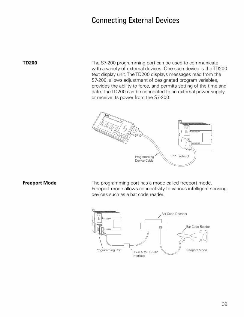
39
Connecting External Devices
TD200 The S7-200 programming port can be used to communicate with a variety of external devices. One such device is the TD200 text display unit. The TD200 displays messages read from the S7-200, allows adjustment of designated program variables, provides the ability to force, and permits setting of the time and date. The TD200 can be connected to an external power supply or receive its power from the S7-200.
Freeport Mode The programming port has a mode called freeport mode. Freeport mode allows connectivity to various intelligent sensing devices such as a bar code reader.
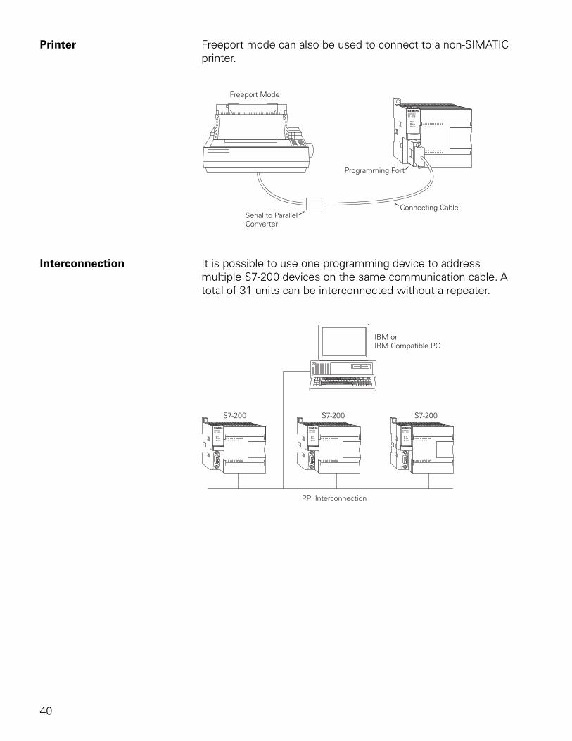
40
Printer Freeport mode can also be used to connect to a non-SIMATIC printer.
Interconnection It is possible to use one programming device to address multiple S7-200 devices on the same communication cable. A total of 31 units can be interconnected without a repeater.
41
Programming A PLC
STEP 7-Micro/WIN32 is the program software used with the S7-200 PLC to create the PLC operating program. STEP 7 consists of a number of instructions that must be arranged in a logical order to obtain the desired PLC operation. These instructions are divided into three groups: standard instructions, special instructions, and high-speed instructions.
Standard Instructions Standard instructions consists of instructions that are found in most programs. Standard instructions include; timer, counter, math, logical, increment/decrement/invert, move, and block instructions.
Special Instructions Special instructions are used to manipulate data. Special instructions include shift, table, find, conversion, for/next, and real-time instructions.
High-Speed Instructions High-speed instructions allow for events and interrupts to occur independent of the PLC scan time. These include high-speed counters, interrupts, output, and transmit instructions.
It is not the purpose of this text to explain all of the instructions and capabilities. A few of the more common instructions necessary for a basic understanding of PLC operation will be discussed. PLC operation is limited only by the hardware capabilities and the ingenuity of the person programming it. Refer to the SIMATIC S7-200 Programmable Controller System Manual for detailed information concerning these instructions.
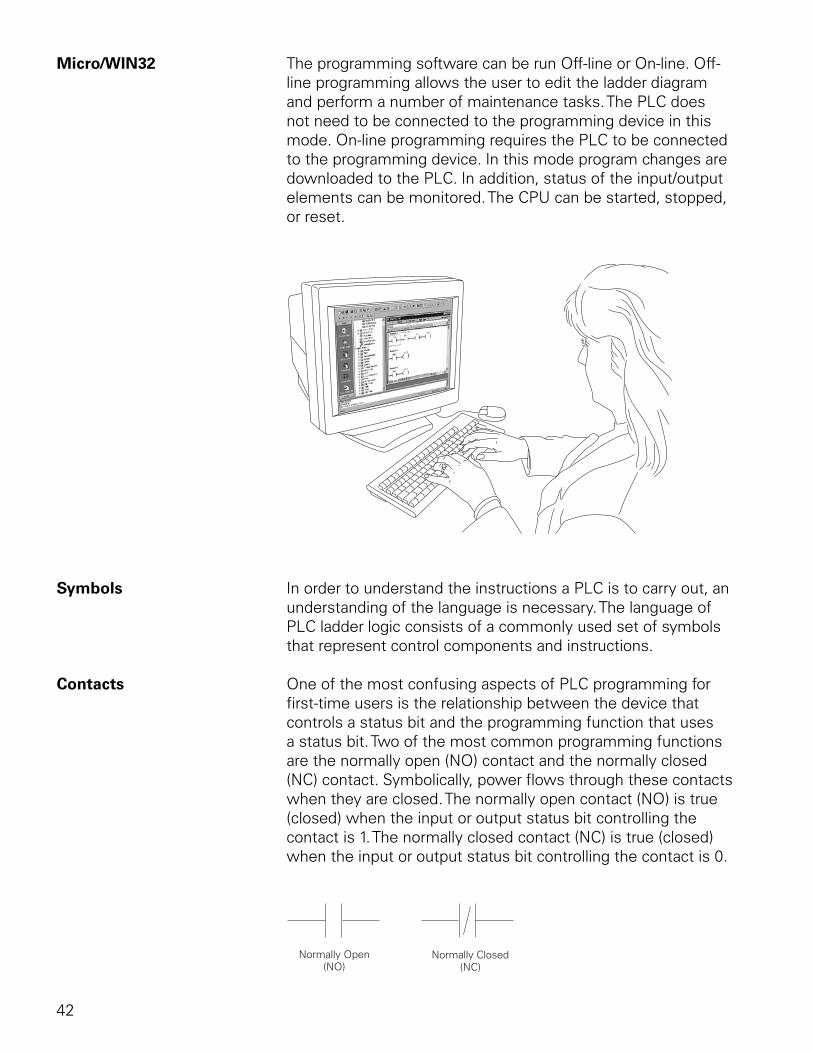
42
Micro/WIN32 The programming software can be run Off-line or On-line. Off-line programming allows the user to edit the ladder diagram and perform a number of maintenance tasks. The PLC does not need to be connected to the programming device in this mode. On-line programming requires the PLC to be connected to the programming device. In this mode program changes are downloaded to the PLC. In addition, status of the input/output elements can be monitored. The CPU can be started, stopped, or reset.
Symbols In order to understand the instructions a PLC is to carry out, an understanding of the language is necessary. The language of PLC ladder logic consists of a commonly used set of symbols that represent control components and instructions.
Contacts One of the most confusing aspects of PLC programming for first-time users is the relationship between the device that controls a status bit and the programming function that uses a status bit. Two of the most common programming functions are the normally open (NO) contact and the normally closed (NC) contact. Symbolically, power flows through these contacts when they are closed. The normally open contact (NO) is true (closed) when the input or output status bit controlling the contact is 1. The normally closed contact (NC) is true (closed) when the input or output status bit controlling the contact is 0.
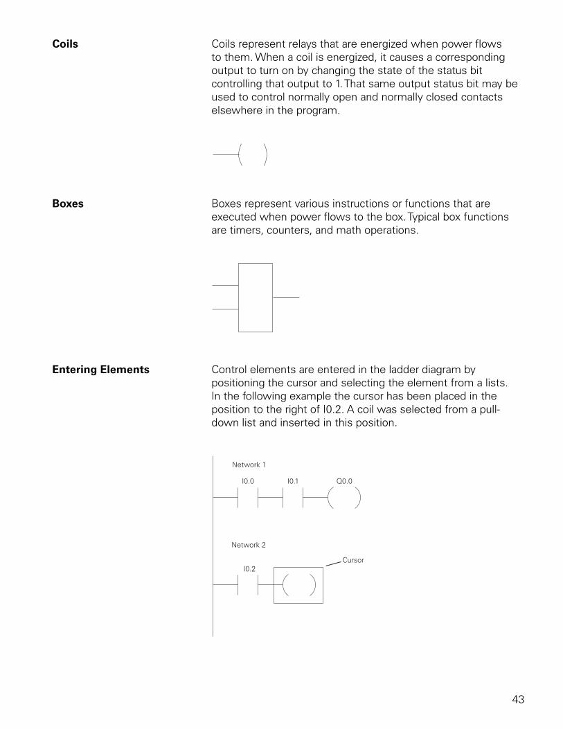
43
Coils Coils represent relays that are energized when power flows to them. When a coil is energized, it causes a corresponding output to turn on by changing the state of the status bit controlling that output to 1. That same output status bit may be used to control normally open and normally closed contacts elsewhere in the program.
Boxes Boxes represent various instructions or functions that are executed when power flows to the box. Typical box functions are timers, counters, and math operations.
Entering Elements Control elements are entered in the ladder diagram by positioning the cursor and selecting the element from a lists. In the following example the cursor has been placed in the position to the right of I0.2. A coil was selected from a pull-down list and inserted in this position.
Network 1
Network 2
I0.0 I0.1
I0.2
Q0.0
Cursor
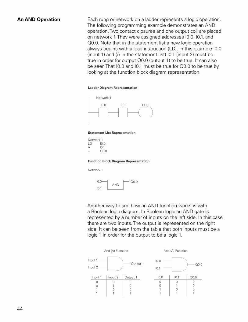
44
An AND Operation Each rung or network on a ladder represents a logic operation. The following programming example demonstrates an AND operation. Two contact closures and one output coil are placed on network 1. They were assigned addresses I0.0, I0.1, and Q0.0. Note that in the statement list a new logic operation always begins with a load instruction (LD). In this example I0.0 (input 1) and (A in the statement list) I0.1 (input 2) must be true in order for output Q0.0 (output 1) to be true. It can also be seen That I0.0 and I0.1 must be true for Q0.0 to be true by looking at the function block diagram representation.
Another way to see how an AND function works is with a Boolean logic diagram. In Boolean logic an AND gate is represented by a number of inputs on the left side. In this case there are two inputs. The output is represented on the right side. It can be seen from the table that both inputs must be a logic 1 in order for the output to be a logic 1.
I0.0
I0.0
I0.1
I0.1
Q0.0
Q0.0
0011
0101
0001
And (A) Function
Input 1
Input 1
Input 2
Input 2
Output 1
Output 1
0011
0101
0001
And (A) Function
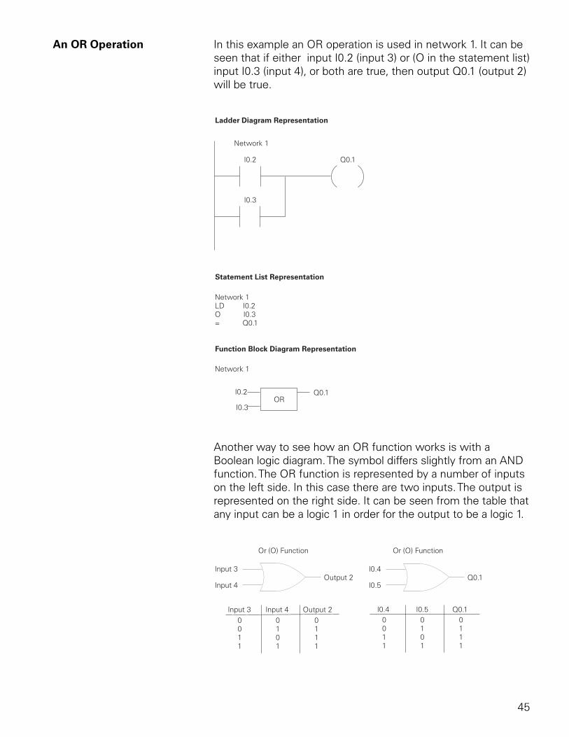
45
An OR Operation In this example an OR operation is used in network 1. It can be seen that if either input I0.2 (input 3) or (O in the statement list) input I0.3 (input 4), or both are true, then output Q0.1 (output 2) will be true.
Another way to see how an OR function works is with a Boolean logic diagram. The symbol differs slightly from an AND function. The OR function is represented by a number of inputs on the left side. In this case there are two inputs. The output is represented on the right side. It can be seen from the table that any input can be a logic 1 in order for the output to be a logic 1.
Input 3
Input 3
Input 4
Input 4
Output 2
Output 2
0011
0101
0111
Or (O) Function
I0.4
I0.4
I0.5
I0.5
Q0.1
Q0.1
0011
0101
0111
Or (O) Function
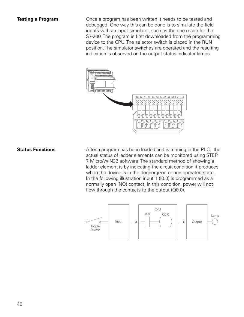
46
Testing a Program Once a program has been written it needs to be tested and debugged. One way this can be done is to simulate the field inputs with an input simulator, such as the one made for the S7-200. The program is first downloaded from the programming device to the CPU. The selector switch is placed in the RUN position. The simulator switches are operated and the resulting indication is observed on the output status indicator lamps.
Status Functions After a program has been loaded and is running in the PLC, the actual status of ladder elements can be monitored using STEP 7 Micro/WIN32 software. The standard method of showing a ladder element is by indicating the circuit condition it produces when the device is in the deenergized or non operated state. In the following illustration input 1 (I0.0) is programmed as a normally open (NO) contact. In this condition, power will not flow through the contacts to the output (Q0.0).
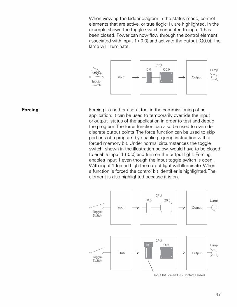
47
When viewing the ladder diagram in the status mode, control elements that are active, or true (logic 1), are highlighted. In the example shown the toggle switch connected to input 1 has been closed. Power can now flow through the control element associated with input 1 (I0.0) and activate the output (Q0.0). The lamp will illuminate.
Forcing Forcing is another useful tool in the commissioning of an application. It can be used to temporarily override the input or output status of the application in order to test and debug the program. The force function can also be used to override discrete output points. The force function can be used to skip portions of a program by enabling a jump instruction with a forced memory bit. Under normal circumstances the toggle switch, shown in the illustration below, would have to be closed to enable input 1 (I0.0) and turn on the output light. Forcing enables input 1 even though the input toggle switch is open. With input 1 forced high the output light will illuminate. When a function is forced the control bit identifier is highlighted. The element is also highlighted because it is on.
48
The following table shows the appearance of ladder elements in the Off, forced, and On condition.
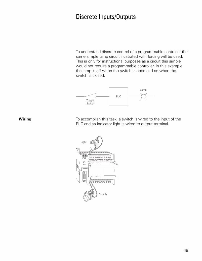
49
Discrete Inputs/Outputs
To understand discrete control of a programmable controller the same simple lamp circuit illustrated with forcing will be used. This is only for instructional purposes as a circuit this simple would not require a programmable controller. In this example the lamp is off when the switch is open and on when the switch is closed.
Wiring To accomplish this task, a switch is wired to the input of the PLC and an indicator light is wired to output terminal.
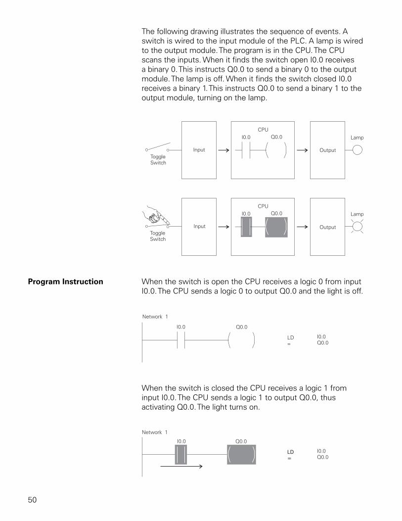
50
The following drawing illustrates the sequence of events. A switch is wired to the input module of the PLC. A lamp is wired to the output module. The program is in the CPU. The CPU scans the inputs. When it finds the switch open I0.0 receives a binary 0. This instructs Q0.0 to send a binary 0 to the output module. The lamp is off. When it finds the switch closed I0.0 receives a binary 1. This instructs Q0.0 to send a binary 1 to the output module, turning on the lamp.
Program Instruction When the switch is open the CPU receives a logic 0 from input I0.0. The CPU sends a logic 0 to output Q0.0 and the light is off.
When the switch is closed the CPU receives a logic 1 from input I0.0. The CPU sends a logic 1 to output Q0.0, thus activating Q0.0. The light turns on.
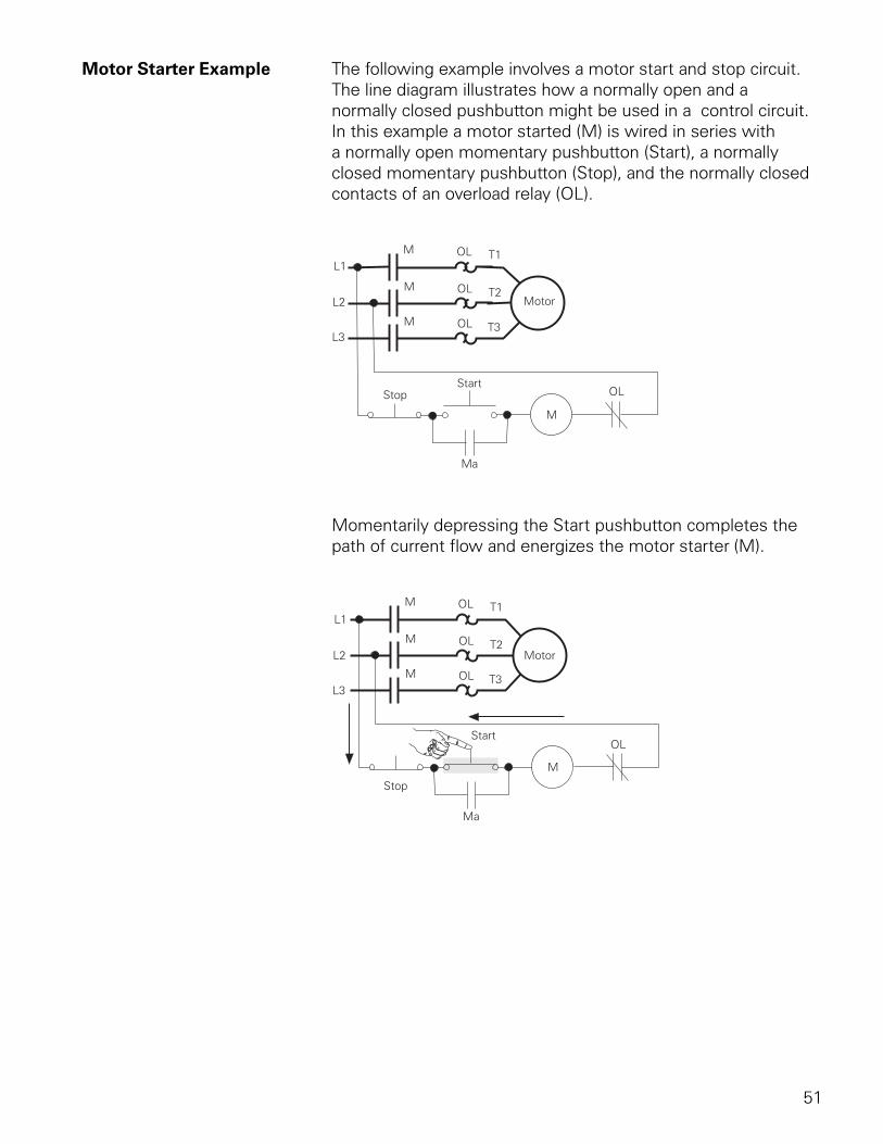
51
Motor Starter Example The following example involves a motor start and stop circuit. The line diagram illustrates how a normally open and a normally closed pushbutton might be used in a control circuit. In this example a motor started (M) is wired in series with a normally open momentary pushbutton (Start), a normally closed momentary pushbutton (Stop), and the normally closed contacts of an overload relay (OL).
Momentarily depressing the Start pushbutton completes the path of current flow and energizes the motor starter (M).
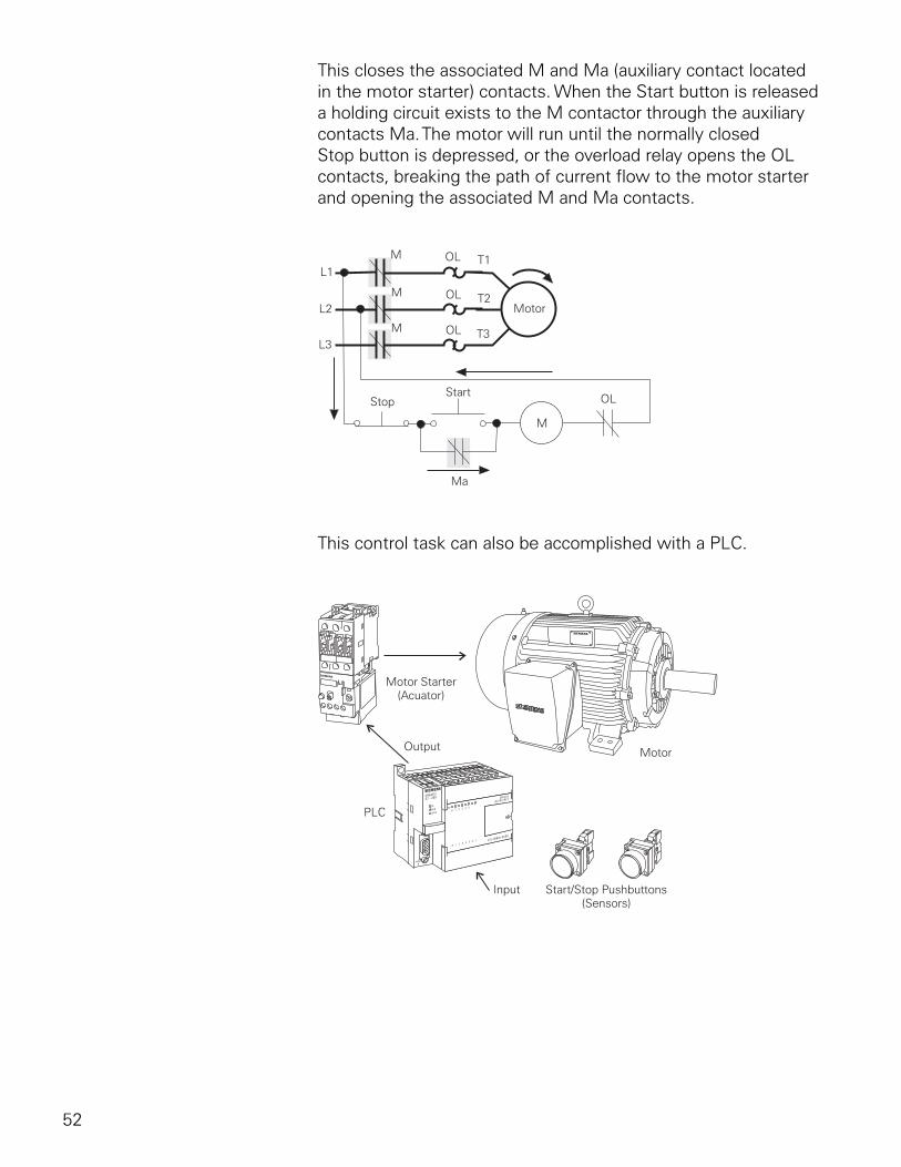
52
This closes the associated M and Ma (auxiliary contact located in the motor starter) contacts. When the Start button is released a holding circuit exists to the M contactor through the auxiliary contacts Ma. The motor will run until the normally closed Stop button is depressed, or the overload relay opens the OL contacts, breaking the path of current flow to the motor starter and opening the associated M and Ma contacts.
This control task can also be accomplished with a PLC.
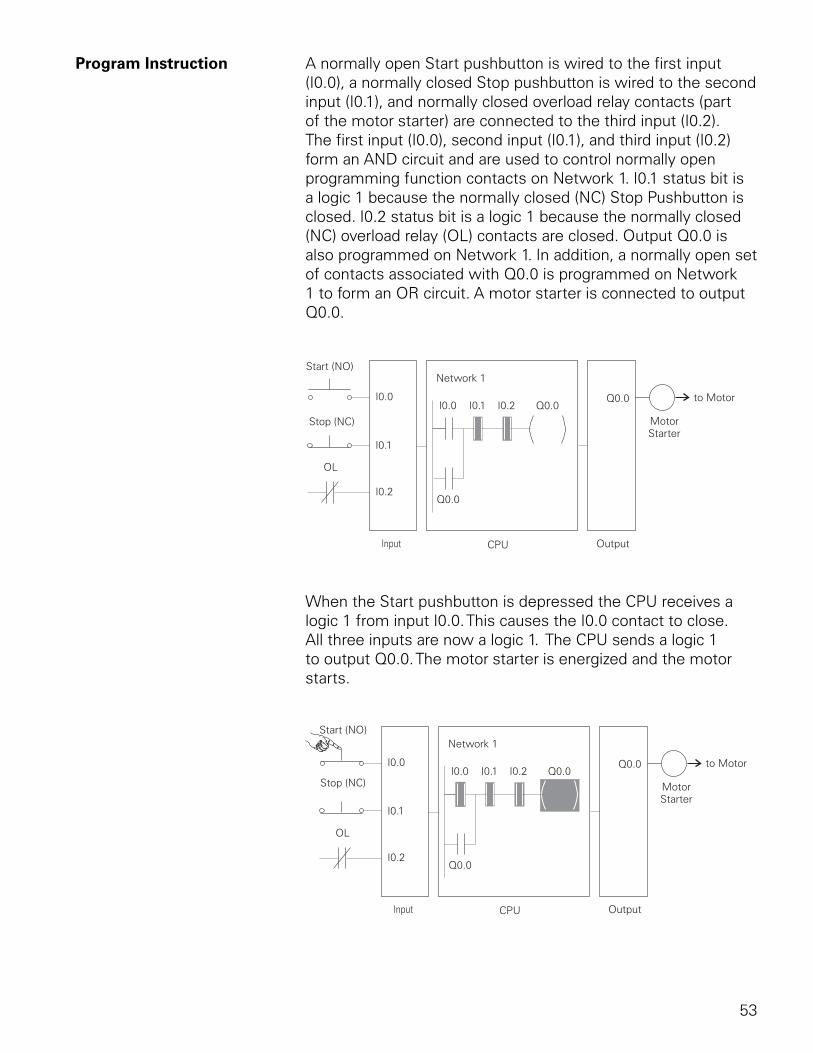
53
Program Instruction A normally open Start pushbutton is wired to the first input (I0.0), a normally closed Stop pushbutton is wired to the second input (I0.1), and normally closed overload relay contacts (part of the motor starter) are connected to the third input (I0.2). The first input (I0.0), second input (I0.1), and third input (I0.2) form an AND circuit and are used to control normally open programming function contacts on Network 1. I0.1 status bit is a logic 1 because the normally closed (NC) Stop Pushbutton is closed. I0.2 status bit is a logic 1 because the normally closed (NC) overload relay (OL) contacts are closed. Output Q0.0 is also programmed on Network 1. In addition, a normally open set of contacts associated with Q0.0 is programmed on Network 1 to form an OR circuit. A motor starter is connected to output Q0.0.
When the Start pushbutton is depressed the CPU receives a logic 1 from input I0.0. This causes the I0.0 contact to close. All three inputs are now a logic 1. The CPU sends a logic 1 to output Q0.0. The motor starter is energized and the motor starts.
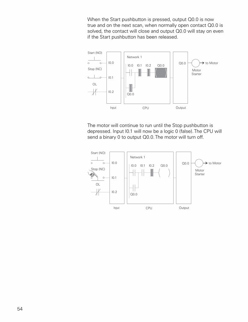
54
When the Start pushbutton is pressed, output Q0.0 is now true and on the next scan, when normally open contact Q0.0 is solved, the contact will close and output Q0.0 will stay on even if the Start pushbutton has been released.
The motor will continue to run until the Stop pushbutton is depressed. Input I0.1 will now be a logic 0 (false). The CPU will send a binary 0 to output Q0.0. The motor will turn off.
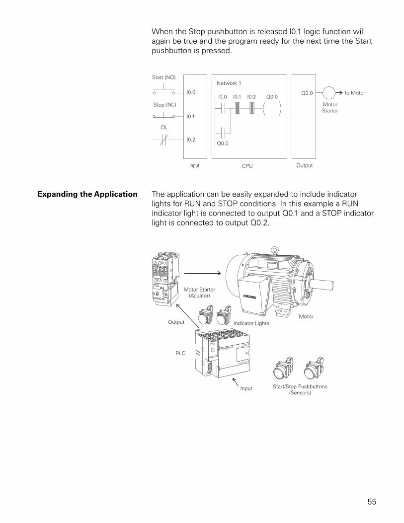
55
When the Stop pushbutton is released I0.1 logic function will again be true and the program ready for the next time the Start pushbutton is pressed.
Expanding the Application The application can be easily expanded to include indicator lights for RUN and STOP conditions. In this example a RUN indicator light is connected to output Q0.1 and a STOP indicator light is connected to output Q0.2.
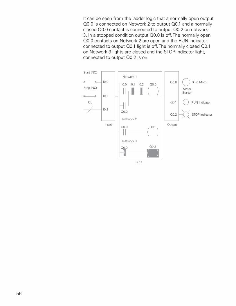
56
It can be seen from the ladder logic that a normally open output Q0.0 is connected on Network 2 to output Q0.1 and a normally closed Q0.0 contact is connected to output Q0.2 on network 3. In a stopped condition output Q0.0 is off. The normally open Q0.0 contacts on Network 2 are open and the RUN indicator, connected to output Q0.1 light is off. The normally closed Q0.1 on Network 3 lights are closed and the STOP indicator light, connected to output Q0.2 is on.
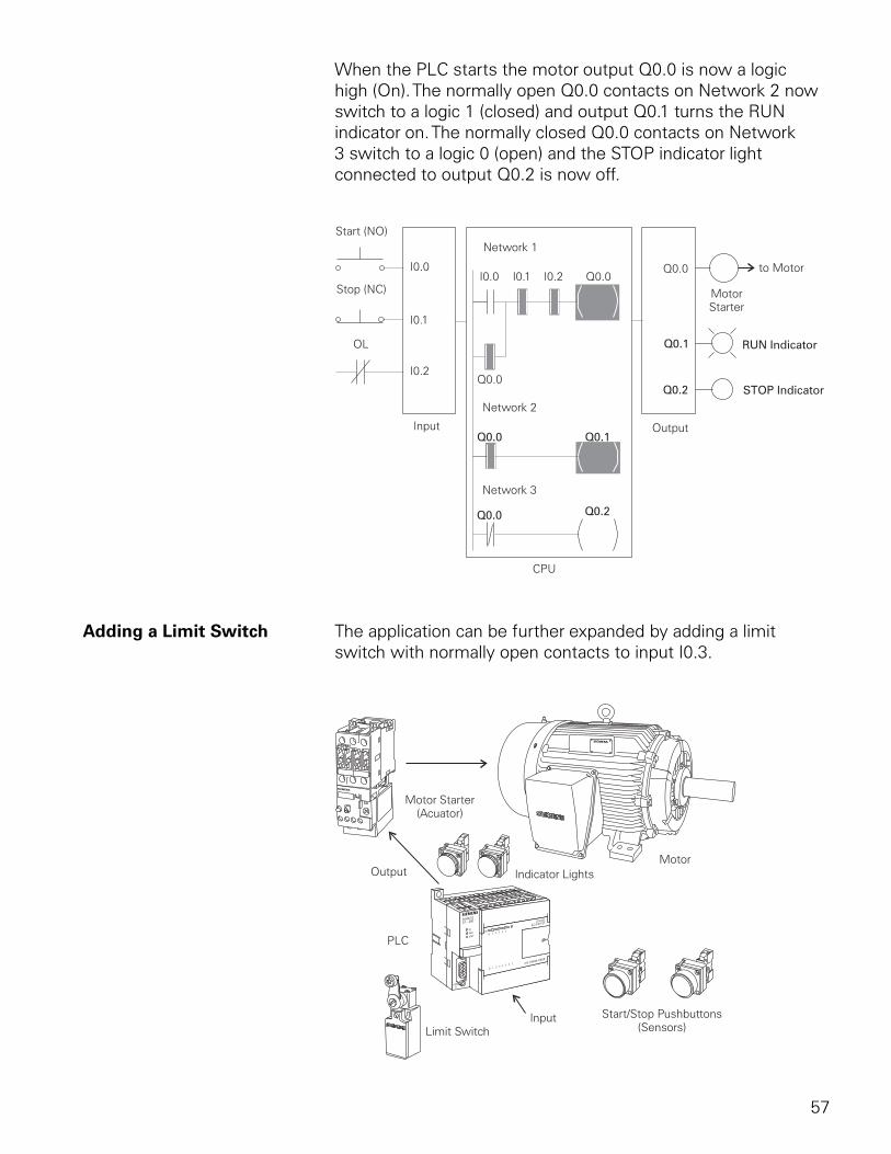
57
When the PLC starts the motor output Q0.0 is now a logic high (On). The normally open Q0.0 contacts on Network 2 now switch to a logic 1 (closed) and output Q0.1 turns the RUN indicator on. The normally closed Q0.0 contacts on Network 3 switch to a logic 0 (open) and the STOP indicator light connected to output Q0.2 is now off.
Adding a Limit Switch The application can be further expanded by adding a limit switch with normally open contacts to input I0.3.
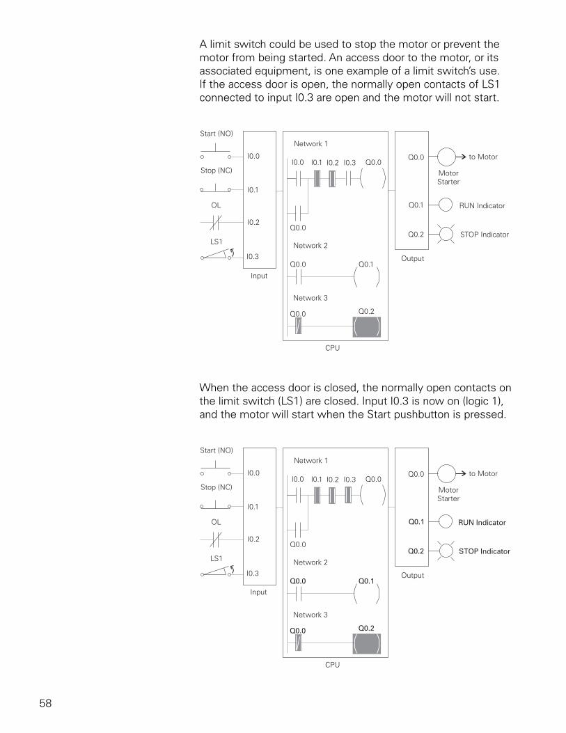
58
A limit switch could be used to stop the motor or prevent the motor from being started. An access door to the motor, or its associated equipment, is one example of a limit switch’s use. If the access door is open, the normally open contacts of LS1 connected to input I0.3 are open and the motor will not start.
When the access door is closed, the normally open contacts on the limit switch (LS1) are closed. Input I0.3 is now on (logic 1), and the motor will start when the Start pushbutton is pressed.
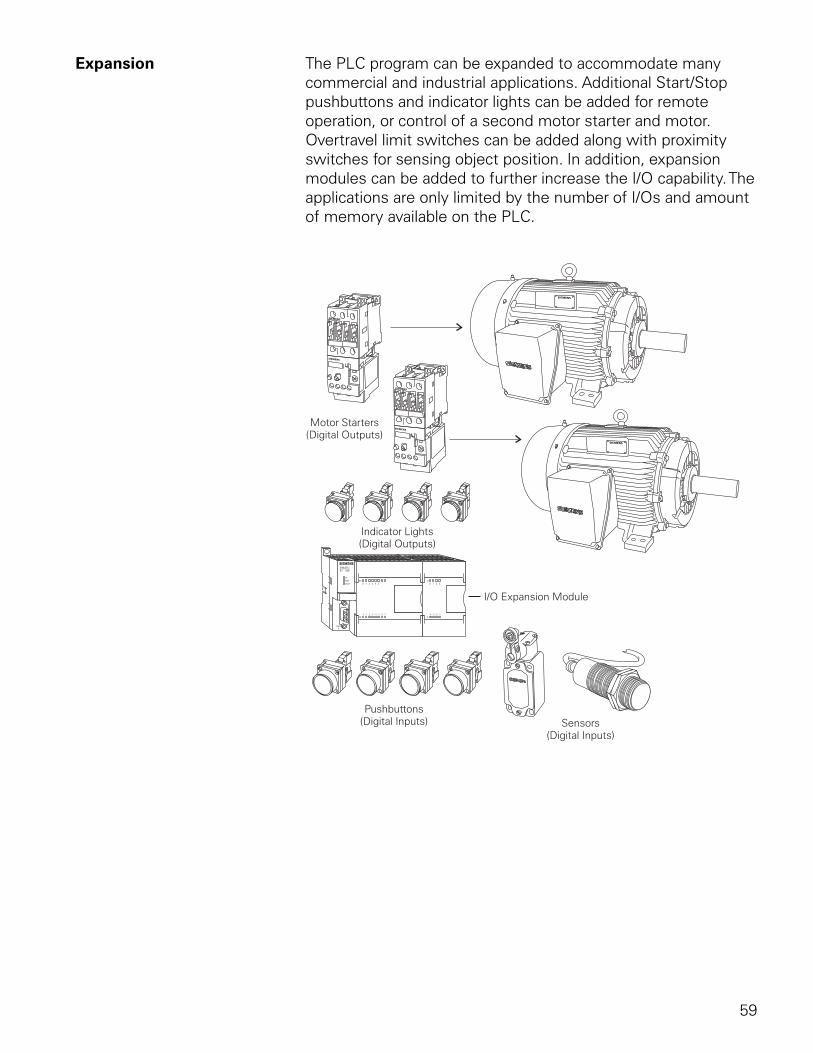
59
Expansion The PLC program can be expanded to accommodate many commercial and industrial applications. Additional Start/Stop pushbuttons and indicator lights can be added for remote operation, or control of a second motor starter and motor. Overtravel limit switches can be added along with proximity switches for sensing object position. In addition, expansion modules can be added to further increase the I/O capability. The applications are only limited by the number of I/Os and amount of memory available on the PLC.
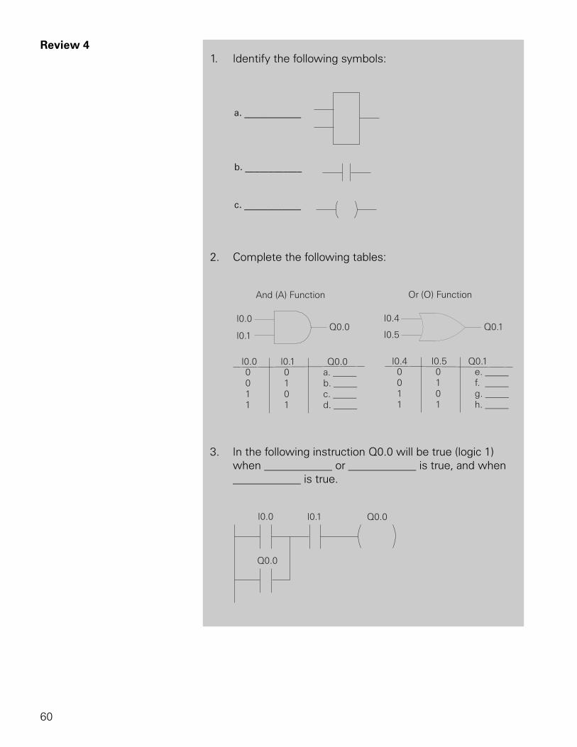
60
Review 41. Identify the following symbols:
a. ____________
b. ____________
c. ____________
2. Complete the following tables:
3. In the following instruction Q0.0 will be true (logic 1) when ____________ or ____________ is true, and when ____________ is true.
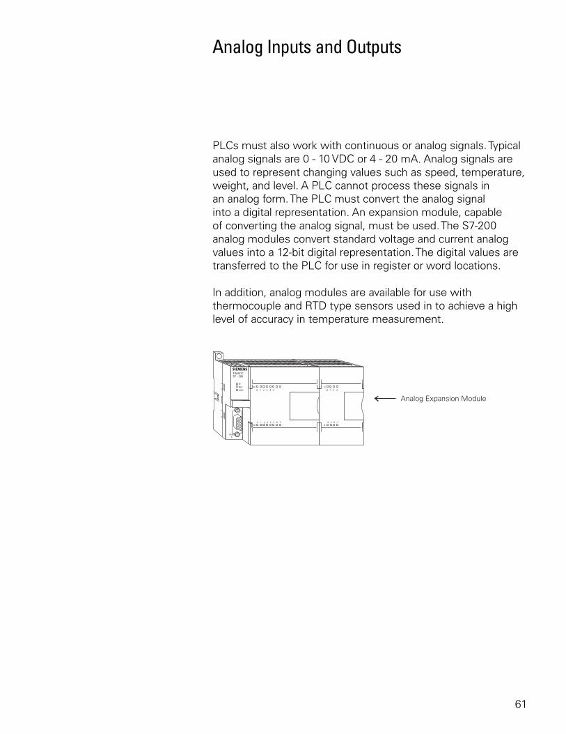
61
Analog Inputs and Outputs
PLCs must also work with continuous or analog signals. Typical analog signals are 0 - 10 VDC or 4 - 20 mA. Analog signals are used to represent changing values such as speed, temperature, weight, and level. A PLC cannot process these signals in an analog form. The PLC must convert the analog signal into a digital representation. An expansion module, capable of converting the analog signal, must be used. The S7-200 analog modules convert standard voltage and current analog values into a 12-bit digital representation. The digital values are transferred to the PLC for use in register or word locations.
In addition, analog modules are available for use with thermocouple and RTD type sensors used in to achieve a high level of accuracy in temperature measurement.
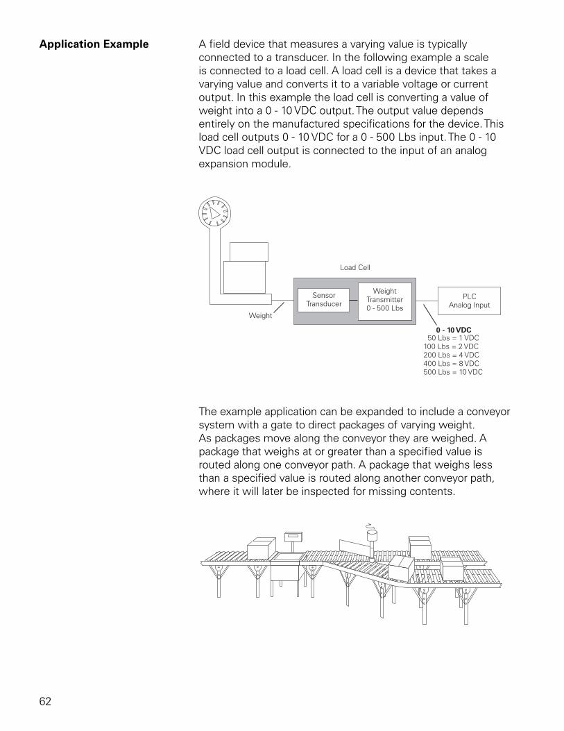
62
Application Example A field device that measures a varying value is typically connected to a transducer. In the following example a scale is connected to a load cell. A load cell is a device that takes a varying value and converts it to a variable voltage or current output. In this example the load cell is converting a value of weight into a 0 - 10 VDC output. The output value depends entirely on the manufactured specifications for the device. This load cell outputs 0 - 10 VDC for a 0 - 500 Lbs input. The 0 - 10 VDC load cell output is connected to the input of an analog expansion module.
The example application can be expanded to include a conveyor system with a gate to direct packages of varying weight. As packages move along the conveyor they are weighed. A package that weighs at or greater than a specified value is routed along one conveyor path. A package that weighs less than a specified value is routed along another conveyor path, where it will later be inspected for missing contents.
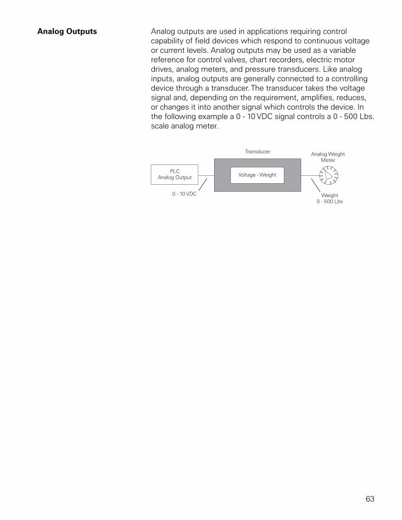
63
Analog Outputs Analog outputs are used in applications requiring control capability of field devices which respond to continuous voltage or current levels. Analog outputs may be used as a variable reference for control valves, chart recorders, electric motor drives, analog meters, and pressure transducers. Like analog inputs, analog outputs are generally connected to a controlling device through a transducer. The transducer takes the voltage signal and, depending on the requirement, amplifies, reduces, or changes it into another signal which controls the device. In the following example a 0 - 10 VDC signal controls a 0 - 500 Lbs. scale analog meter.
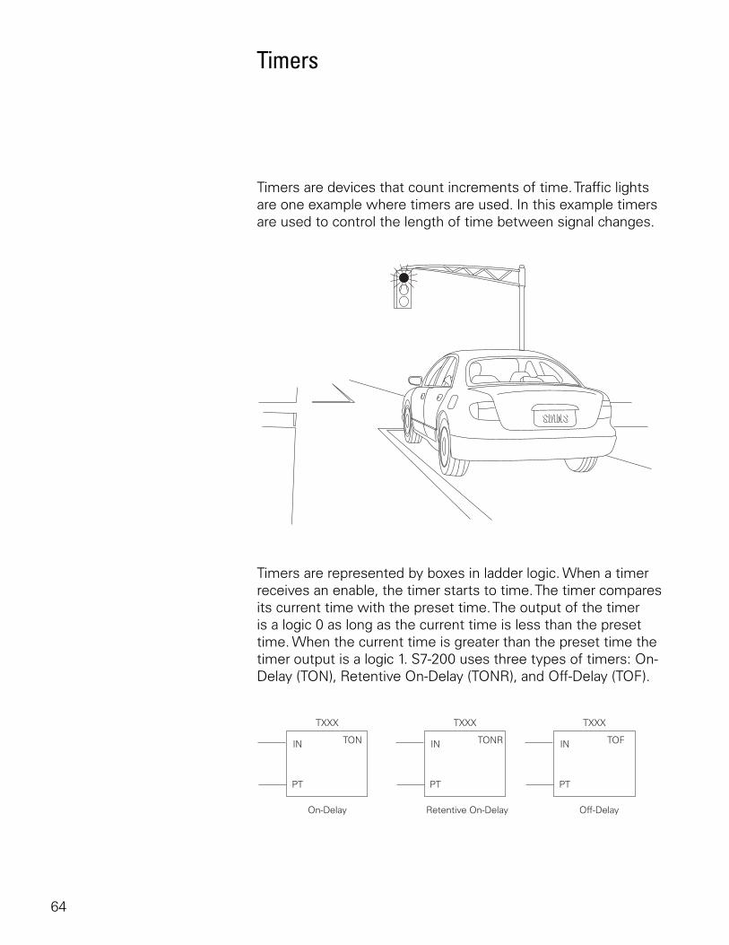
64
Timers
Timers are devices that count increments of time. Traffic lights are one example where timers are used. In this example timers are used to control the length of time between signal changes.
Timers are represented by boxes in ladder logic. When a timer receives an enable, the timer starts to time. The timer compares its current time with the preset time. The output of the timer is a logic 0 as long as the current time is less than the preset time. When the current time is greater than the preset time the timer output is a logic 1. S7-200 uses three types of timers: On-Delay (TON), Retentive On-Delay (TONR), and Off-Delay (TOF).
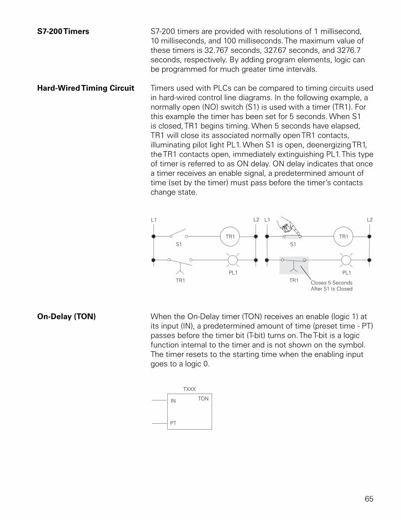
65
S7-200 Timers S7-200 timers are provided with resolutions of 1 millisecond, 10 milliseconds, and 100 milliseconds. The maximum value of these timers is 32.767 seconds, 327.67 seconds, and 3276.7 seconds, respectively. By adding program elements, logic can be programmed for much greater time intervals.
Hard-Wired Timing Circuit Timers used with PLCs can be compared to timing circuits used in hard-wired control line diagrams. In the following example, a normally open (NO) switch (S1) is used with a timer (TR1). For this example the timer has been set for 5 seconds. When S1 is closed, TR1 begins timing. When 5 seconds have elapsed, TR1 will close its associated normally open TR1 contacts, illuminating pilot light PL1. When S1 is open, deenergizing TR1, the TR1 contacts open, immediately extinguishing PL1. This type of timer is referred to as ON delay. ON delay indicates that once a timer receives an enable signal, a predetermined amount of time (set by the timer) must pass before the timer’s contacts change state.
On-Delay (TON) When the On-Delay timer (TON) receives an enable (logic 1) at its input (IN), a predetermined amount of time (preset time - PT) passes before the timer bit (T-bit) turns on. The T-bit is a logic function internal to the timer and is not shown on the symbol. The timer resets to the starting time when the enabling input goes to a logic 0.
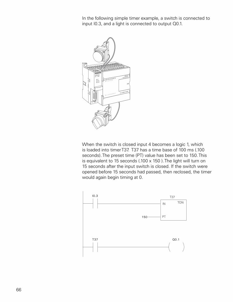
66
In the following simple timer example, a switch is connected to input I0.3, and a light is connected to output Q0.1.
When the switch is closed input 4 becomes a logic 1, which is loaded into timer T37. T37 has a time base of 100 ms (.100 seconds). The preset time (PT) value has been set to 150. This is equivalent to 15 seconds (.100 x 150 ). The light will turn on 15 seconds after the input switch is closed. If the switch were opened before 15 seconds had passed, then reclosed, the timer would again begin timing at 0.
T37
150
I0.3
Q0.1
TON
T37
IN
PT
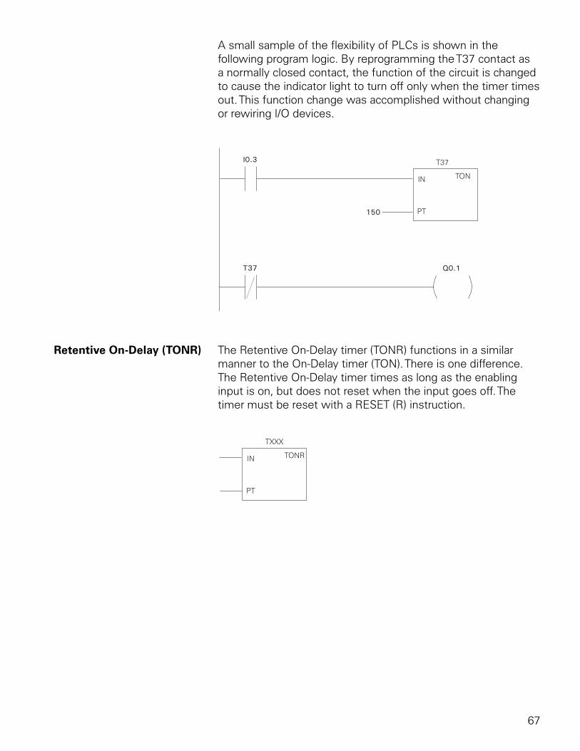
67
A small sample of the flexibility of PLCs is shown in the following program logic. By reprogramming the T37 contact as a normally closed contact, the function of the circuit is changed to cause the indicator light to turn off only when the timer times out. This function change was accomplished without changing or rewiring I/O devices.
T37
150
I0.3
Q0.1
TON
T37
IN
PT
Retentive On-Delay (TONR) The Retentive On-Delay timer (TONR) functions in a similar manner to the On-Delay timer (TON). There is one difference. The Retentive On-Delay timer times as long as the enabling input is on, but does not reset when the input goes off. The timer must be reset with a RESET (R) instruction.
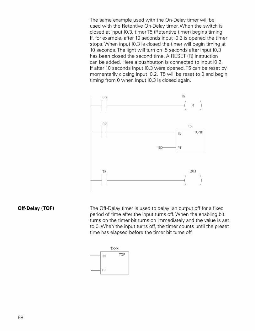
68
The same example used with the On-Delay timer will be used with the Retentive On-Delay timer. When the switch is closed at input I0.3, timer T5 (Retentive timer) begins timing. If, for example, after 10 seconds input I0.3 is opened the timer stops. When input I0.3 is closed the timer will begin timing at 10 seconds. The light will turn on 5 seconds after input I0.3 has been closed the second time. A RESET (R) instruction can be added. Here a pushbutton is connected to input I0.2. If after 10 seconds input I0.3 were opened, T5 can be reset by momentarily closing input I0.2. T5 will be reset to 0 and begin timing from 0 when input I0.3 is closed again.
T5
T5
150
I0.3
I0.2
Q0.1
R
TONR
T5
IN
PT
Off-Delay (TOF) The Off-Delay timer is used to delay an output off for a fixed period of time after the input turns off. When the enabling bit turns on the timer bit turns on immediately and the value is set to 0. When the input turns off, the timer counts until the preset time has elapsed before the timer bit turns off.
TOF
TXXX
IN
PT
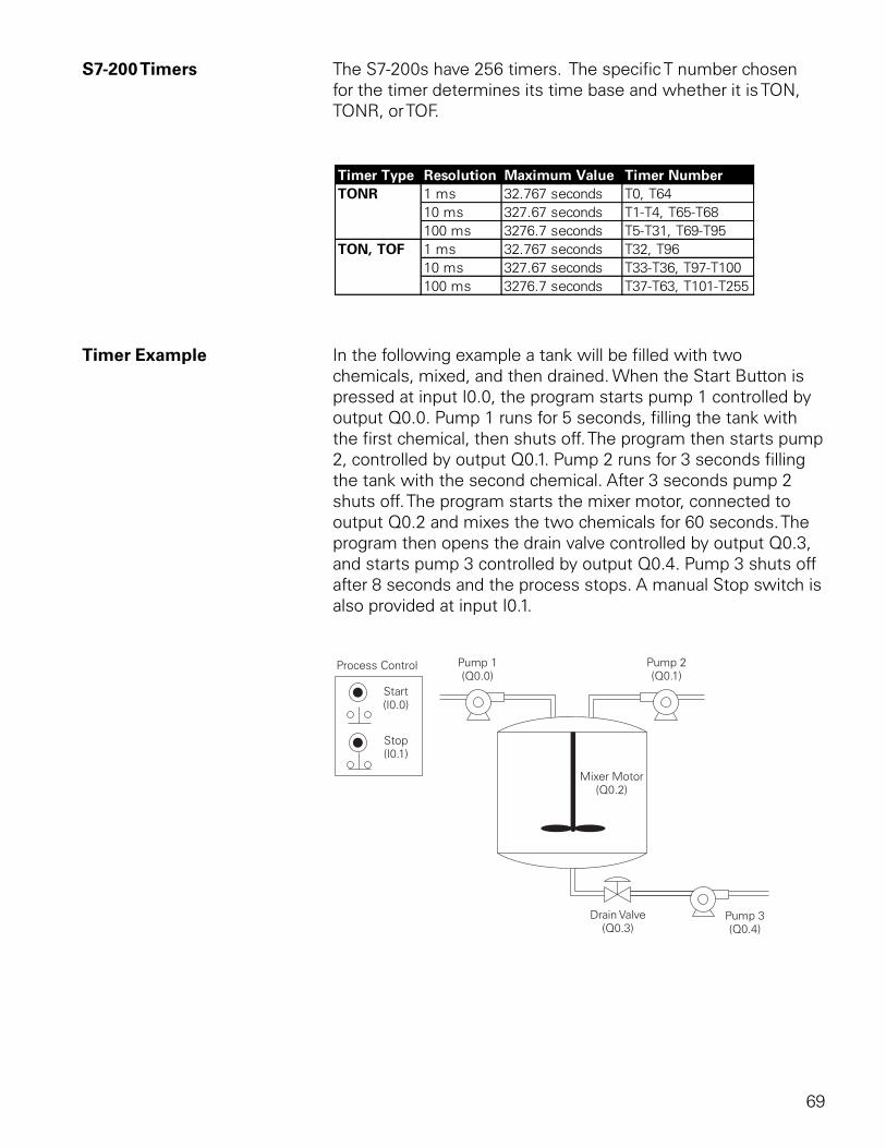
69
S7-200 Timers The S7-200s have 256 timers. The specific T number chosen for the timer determines its time base and whether it is TON, TONR, or TOF.
Timer Example In the following example a tank will be filled with two chemicals, mixed, and then drained. When the Start Button is pressed at input I0.0, the program starts pump 1 controlled by output Q0.0. Pump 1 runs for 5 seconds, filling the tank with the first chemical, then shuts off. The program then starts pump 2, controlled by output Q0.1. Pump 2 runs for 3 seconds filling the tank with the second chemical. After 3 seconds pump 2 shuts off. The program starts the mixer motor, connected to output Q0.2 and mixes the two chemicals for 60 seconds. The program then opens the drain valve controlled by output Q0.3, and starts pump 3 controlled by output Q0.4. Pump 3 shuts off after 8 seconds and the process stops. A manual Stop switch is also provided at input I0.1.
70
Review 51. Analog signals are converted into a ____________
format by the PLC.
2. Three types of timers available in the S7-200 are On-Delay, ____________ On-Delay, and ____________-Delay.
3. The maximum time available on a 100 millisecond time base timer is ____________ seconds.
4. A count of 25 on a 10 millisecond time base timer represents a time of __________ milliseconds.
5. There are ____________ timers in the S7-200.
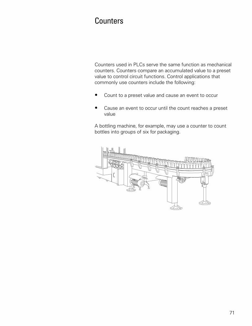
71
Counters
Counters used in PLCs serve the same function as mechanical counters. Counters compare an accumulated value to a preset value to control circuit functions. Control applications that commonly use counters include the following:
• Count to a preset value and cause an event to occur
• Cause an event to occur until the count reaches a preset value
A bottling machine, for example, may use a counter to count bottles into groups of six for packaging.
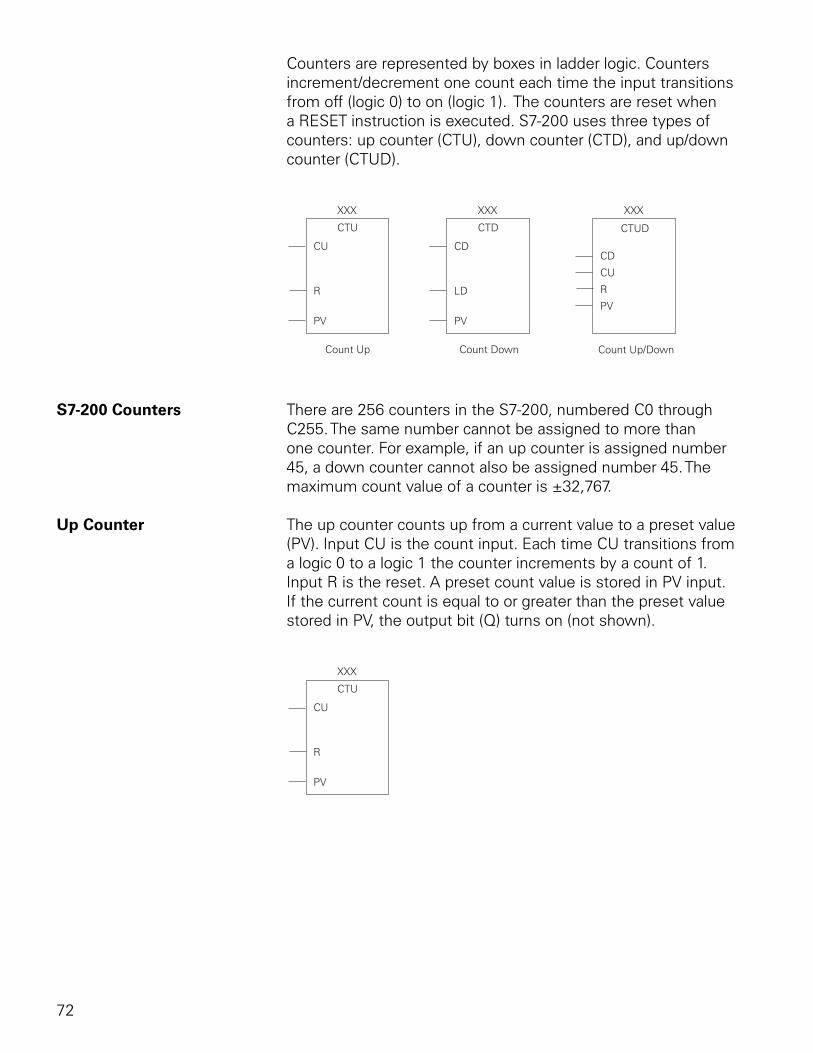
72
Counters are represented by boxes in ladder logic. Counters increment/decrement one count each time the input transitions from off (logic 0) to on (logic 1). The counters are reset when a RESET instruction is executed. S7-200 uses three types of counters: up counter (CTU), down counter (CTD), and up/down counter (CTUD).
Count Up/DownCount Up Count Down
PV PV
R LD
PV
CU CDCD
CU
R
CTU CTD CTUD
XXX XXX XXX
S7-200 Counters There are 256 counters in the S7-200, numbered C0 through C255. The same number cannot be assigned to more than one counter. For example, if an up counter is assigned number 45, a down counter cannot also be assigned number 45. The maximum count value of a counter is ±32,767.
Up Counter The up counter counts up from a current value to a preset value (PV). Input CU is the count input. Each time CU transitions from a logic 0 to a logic 1 the counter increments by a count of 1. Input R is the reset. A preset count value is stored in PV input. If the current count is equal to or greater than the preset value stored in PV, the output bit (Q) turns on (not shown).
PV
R
CU
CTU
XXX
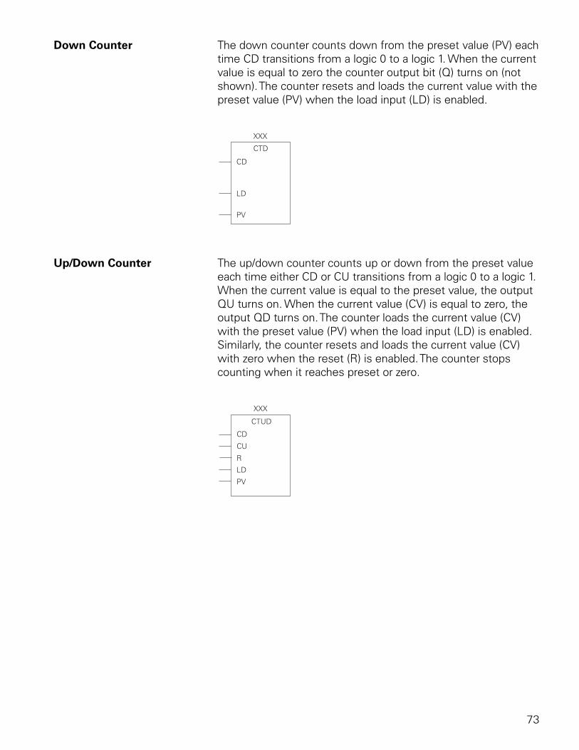
73
Down Counter The down counter counts down from the preset value (PV) each time CD transitions from a logic 0 to a logic 1. When the current value is equal to zero the counter output bit (Q) turns on (not shown). The counter resets and loads the current value with the preset value (PV) when the load input (LD) is enabled.
PV
LD
CD
CTD
XXX
Up/Down Counter The up/down counter counts up or down from the preset value each time either CD or CU transitions from a logic 0 to a logic 1. When the current value is equal to the preset value, the output QU turns on. When the current value (CV) is equal to zero, the output QD turns on. The counter loads the current value (CV) with the preset value (PV) when the load input (LD) is enabled. Similarly, the counter resets and loads the current value (CV) with zero when the reset (R) is enabled. The counter stops counting when it reaches preset or zero.
PV
LD
CD
CU
R
CTUD
XXX
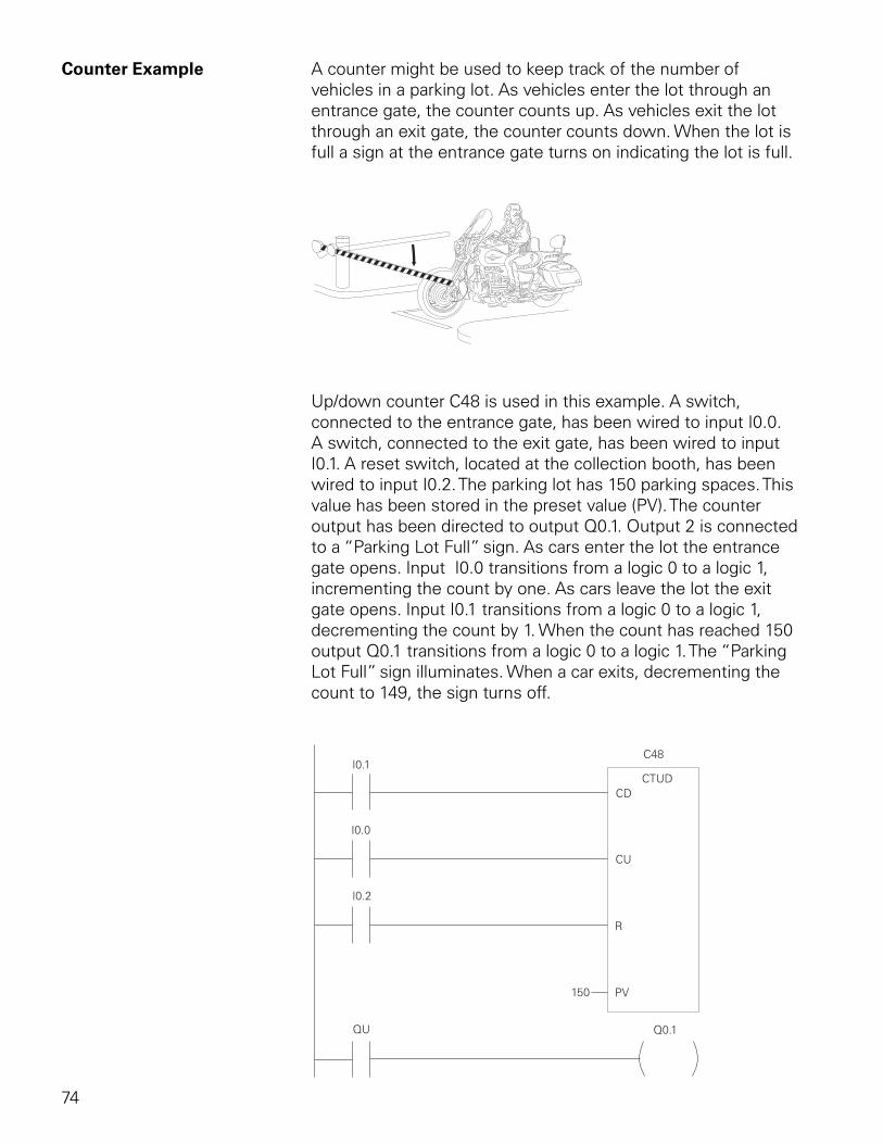
74
Counter Example A counter might be used to keep track of the number of vehicles in a parking lot. As vehicles enter the lot through an entrance gate, the counter counts up. As vehicles exit the lot through an exit gate, the counter counts down. When the lot is full a sign at the entrance gate turns on indicating the lot is full.
Up/down counter C48 is used in this example. A switch, connected to the entrance gate, has been wired to input I0.0. A switch, connected to the exit gate, has been wired to input I0.1. A reset switch, located at the collection booth, has been wired to input I0.2. The parking lot has 150 parking spaces. This value has been stored in the preset value (PV). The counter output has been directed to output Q0.1. Output 2 is connected to a “Parking Lot Full” sign. As cars enter the lot the entrance gate opens. Input I0.0 transitions from a logic 0 to a logic 1, incrementing the count by one. As cars leave the lot the exit gate opens. Input I0.1 transitions from a logic 0 to a logic 1, decrementing the count by 1. When the count has reached 150 output Q0.1 transitions from a logic 0 to a logic 1. The “Parking Lot Full” sign illuminates. When a car exits, decrementing the count to 149, the sign turns off.
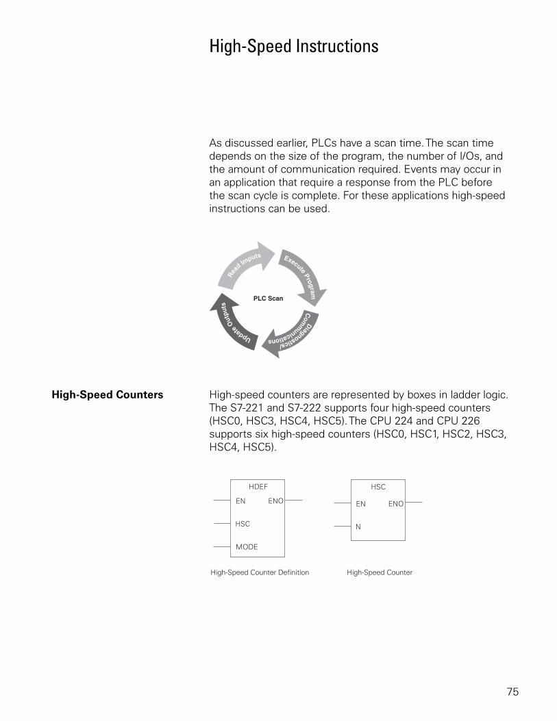
75
High-Speed Instructions
As discussed earlier, PLCs have a scan time. The scan time depends on the size of the program, the number of I/Os, and the amount of communication required. Events may occur in an application that require a response from the PLC before the scan cycle is complete. For these applications high-speed instructions can be used.
High-Speed Counters High-speed counters are represented by boxes in ladder logic. The S7-221 and S7-222 supports four high-speed counters (HSC0, HSC3, HSC4, HSC5). The CPU 224 and CPU 226 supports six high-speed counters (HSC0, HSC1, HSC2, HSC3, HSC4, HSC5).
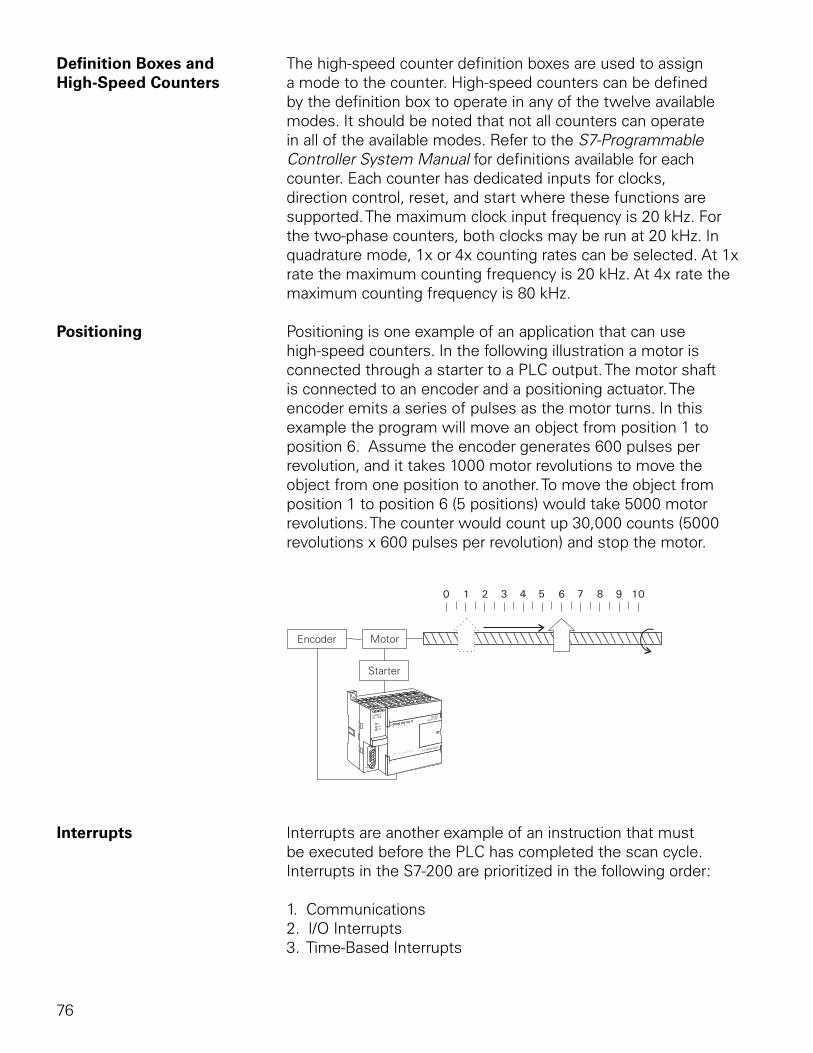
76
Definition Boxes and The high-speed counter definition boxes are used to assign High-Speed Counters a mode to the counter. High-speed counters can be defined
by the definition box to operate in any of the twelve available modes. It should be noted that not all counters can operate in all of the available modes. Refer to the S7-Programmable Controller System Manual for definitions available for each counter. Each counter has dedicated inputs for clocks, direction control, reset, and start where these functions are supported. The maximum clock input frequency is 20 kHz. For the two-phase counters, both clocks may be run at 20 kHz. In quadrature mode, 1x or 4x counting rates can be selected. At 1x rate the maximum counting frequency is 20 kHz. At 4x rate the maximum counting frequency is 80 kHz.
Positioning Positioning is one example of an application that can use high-speed counters. In the following illustration a motor is connected through a starter to a PLC output. The motor shaft is connected to an encoder and a positioning actuator. The encoder emits a series of pulses as the motor turns. In this example the program will move an object from position 1 to position 6. Assume the encoder generates 600 pulses per revolution, and it takes 1000 motor revolutions to move the object from one position to another. To move the object from position 1 to position 6 (5 positions) would take 5000 motor revolutions. The counter would count up 30,000 counts (5000 revolutions x 600 pulses per revolution) and stop the motor.
Interrupts Interrupts are another example of an instruction that must be executed before the PLC has completed the scan cycle. Interrupts in the S7-200 are prioritized in the following order:
1. Communications 2. I/O Interrupts 3. Time-Based Interrupts
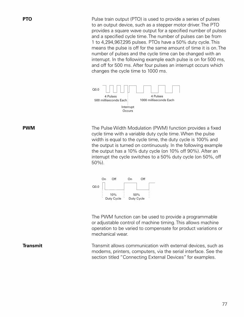
77
PTO Pulse train output (PTO) is used to provide a series of pulses to an output device, such as a stepper motor driver. The PTO provides a square wave output for a specified number of pulses and a specified cycle time. The number of pulses can be from 1 to 4,294,967,295 pulses. PTOs have a 50% duty cycle. This means the pulse is off for the same amount of time it is on. The number of pulses and the cycle time can be changed with an interrupt. In the following example each pulse is on for 500 ms, and off for 500 ms. After four pulses an interrupt occurs which changes the cycle time to 1000 ms.
Q0.0
4 Pulses500 milliseconds Each
4 Pulses1000 milliseconds Each
InterruptOccurs
PWM The Pulse Width Modulation (PWM) function provides a fixed cycle time with a variable duty cycle time. When the pulse width is equal to the cycle time, the duty cycle is 100% and the output is turned on continuously. In the following example the output has a 10% duty cycle (on 10% off 90%). After an interrupt the cycle switches to a 50% duty cycle (on 50%, off 50%).
Q0.0
On OnOff Off
10%Duty Cycle
50%Duty Cycle
The PWM function can be used to provide a programmable or adjustable control of machine timing. This allows machine operation to be varied to compensate for product variations or mechanical wear.
Transmit Transmit allows communication with external devices, such as modems, printers, computers, via the serial interface. See the section titled “Connecting External Devices” for examples.
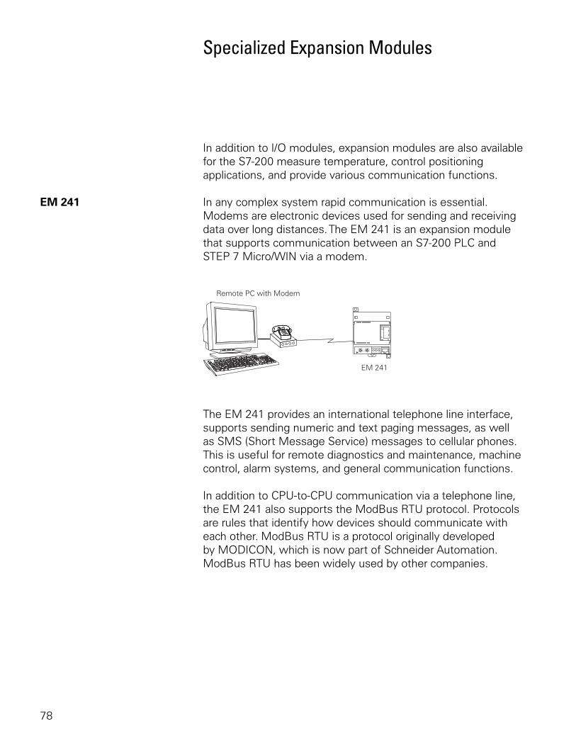
78
Specialized Expansion Modules
In addition to I/O modules, expansion modules are also available for the S7-200 measure temperature, control positioning applications, and provide various communication functions.
EM 241 In any complex system rapid communication is essential. Modems are electronic devices used for sending and receiving data over long distances. The EM 241 is an expansion module that supports communication between an S7-200 PLC and STEP 7 Micro/WIN via a modem.
The EM 241 provides an international telephone line interface, supports sending numeric and text paging messages, as well as SMS (Short Message Service) messages to cellular phones. This is useful for remote diagnostics and maintenance, machine control, alarm systems, and general communication functions.
In addition to CPU-to-CPU communication via a telephone line, the EM 241 also supports the ModBus RTU protocol. Protocols are rules that identify how devices should communicate with each other. ModBus RTU is a protocol originally developed by MODICON, which is now part of Schneider Automation. ModBus RTU has been widely used by other companies.
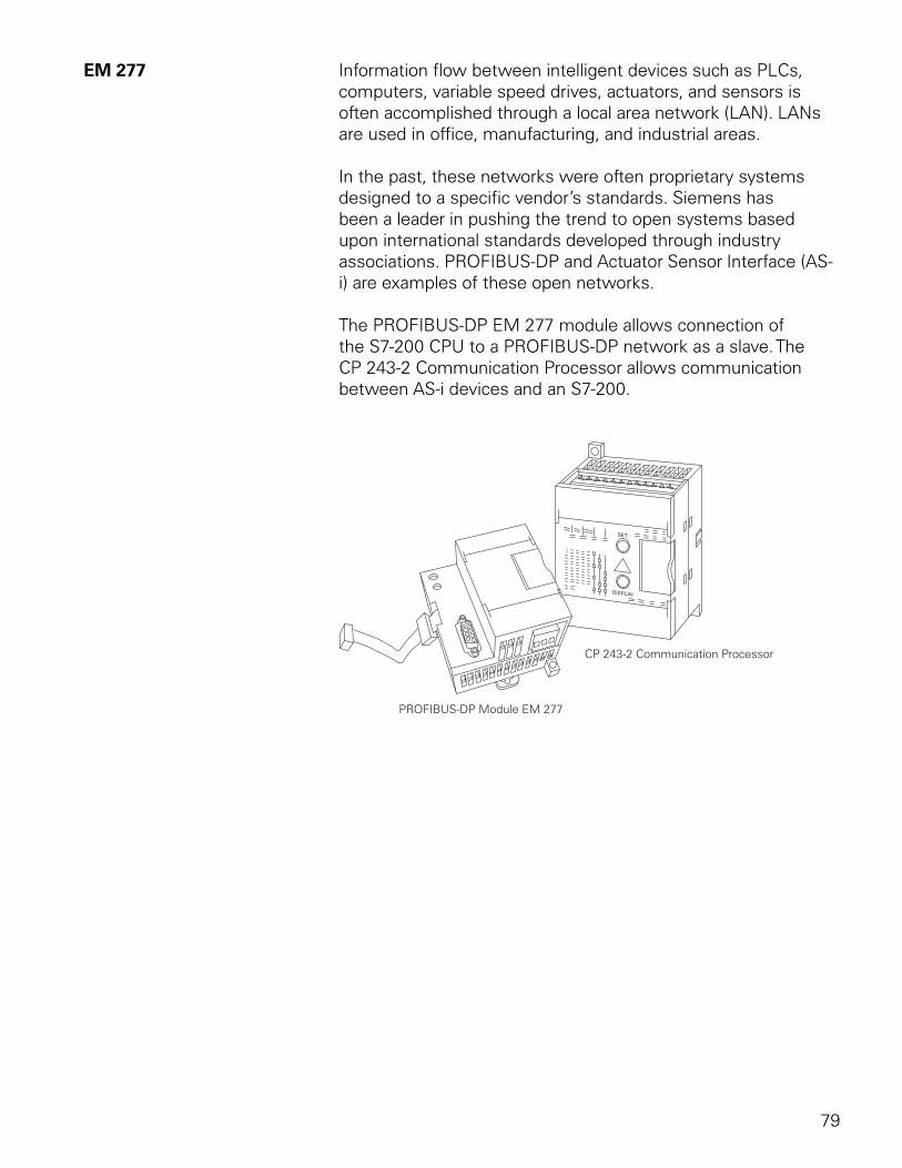
79
EM 277 Information flow between intelligent devices such as PLCs, computers, variable speed drives, actuators, and sensors is often accomplished through a local area network (LAN). LANs are used in office, manufacturing, and industrial areas.
In the past, these networks were often proprietary systems designed to a specific vendor’s standards. Siemens has been a leader in pushing the trend to open systems based upon international standards developed through industry associations. PROFIBUS-DP and Actuator Sensor Interface (AS-i) are examples of these open networks.
The PROFIBUS-DP EM 277 module allows connection of the S7-200 CPU to a PROFIBUS-DP network as a slave. The CP 243-2 Communication Processor allows communication between AS-i devices and an S7-200.
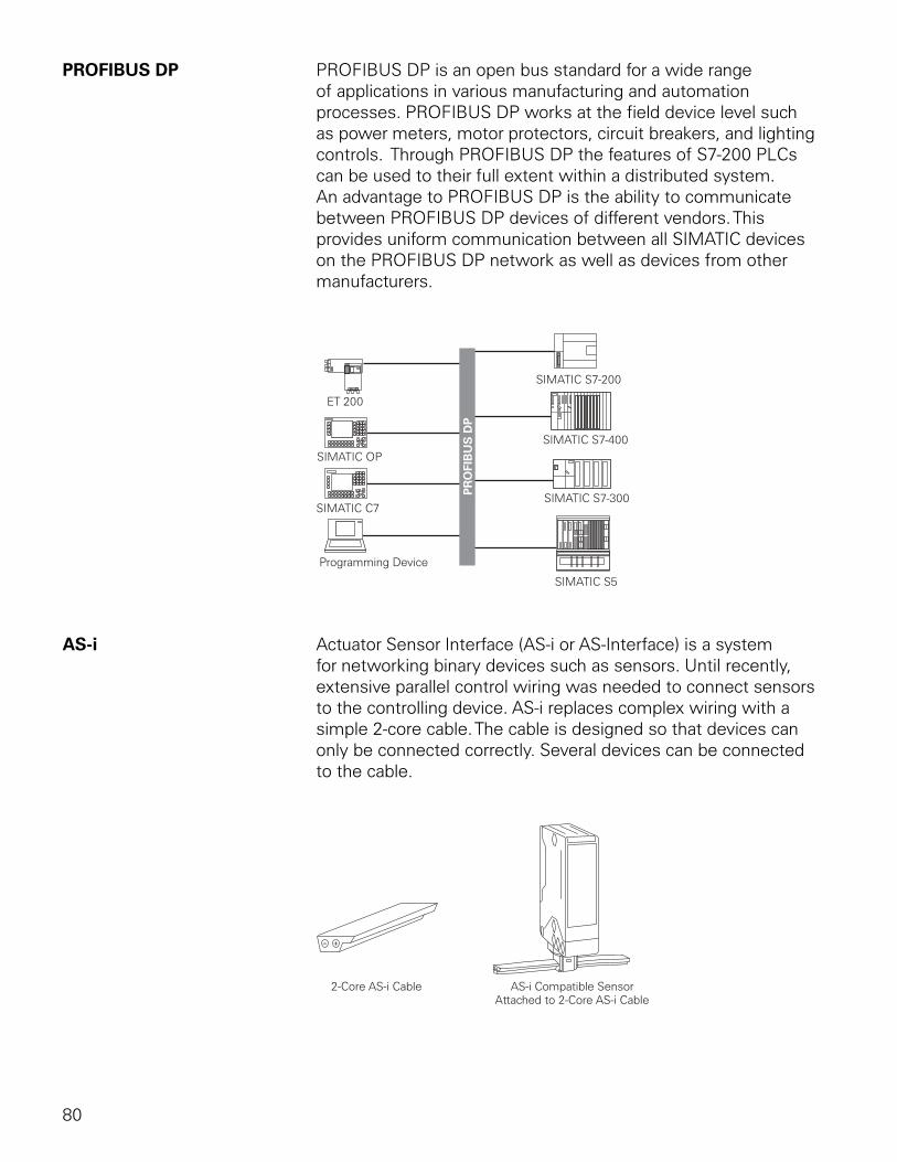
80
PROFIBUS DP PROFIBUS DP is an open bus standard for a wide range of applications in various manufacturing and automation processes. PROFIBUS DP works at the field device level such as power meters, motor protectors, circuit breakers, and lighting controls. Through PROFIBUS DP the features of S7-200 PLCs can be used to their full extent within a distributed system. An advantage to PROFIBUS DP is the ability to communicate between PROFIBUS DP devices of different vendors. This provides uniform communication between all SIMATIC devices on the PROFIBUS DP network as well as devices from other manufacturers.
AS-i Actuator Sensor Interface (AS-i or AS-Interface) is a system for networking binary devices such as sensors. Until recently, extensive parallel control wiring was needed to connect sensors to the controlling device. AS-i replaces complex wiring with a simple 2-core cable. The cable is designed so that devices can only be connected correctly. Several devices can be connected to the cable.
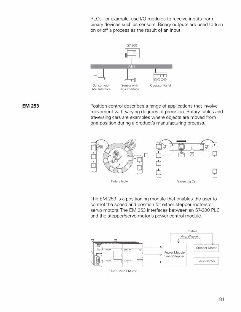
81
PLCs, for example, use I/O modules to receive inputs from binary devices such as sensors. Binary outputs are used to turn on or off a process as the result of an input.
EM 253 Position control describes a range of applications that involve movement with varying degrees of precision. Rotary tables and traversing cars are examples where objects are moved from one position during a product’s manufacturing process.
The EM 253 is a positioning module that enables the user to control the speed and position for either stepper motors or servo motors. The EM 253 interfaces between an S7-200 PLC and the stepper/servo motor’s power control module.
82
EM 253 Features The EM 253 provides functionality for single-axis, open-loop position control. Features of the module include:
• High-speed control with a range of 12 - 200,000 pulse per second
• Jerk (S curve) or linear acceleration/deceleration
• Configurable measuring system to enter data as engineering units (such as inches or centimeters) or number of pulses
• Configuarble backlash compensation
• Supports absolute, relative, and manual methods of position control
• Continuous operation
• Provides up to 25 motion profiles with up to 4 speed changes per profile
• Four different reference-point seek modes, with a choice of the starting seek direction and final approach direction for each sequence
Web Site For more information and sales support on the S7-200 visit our web site at http://www.siemens.com/s7-200.
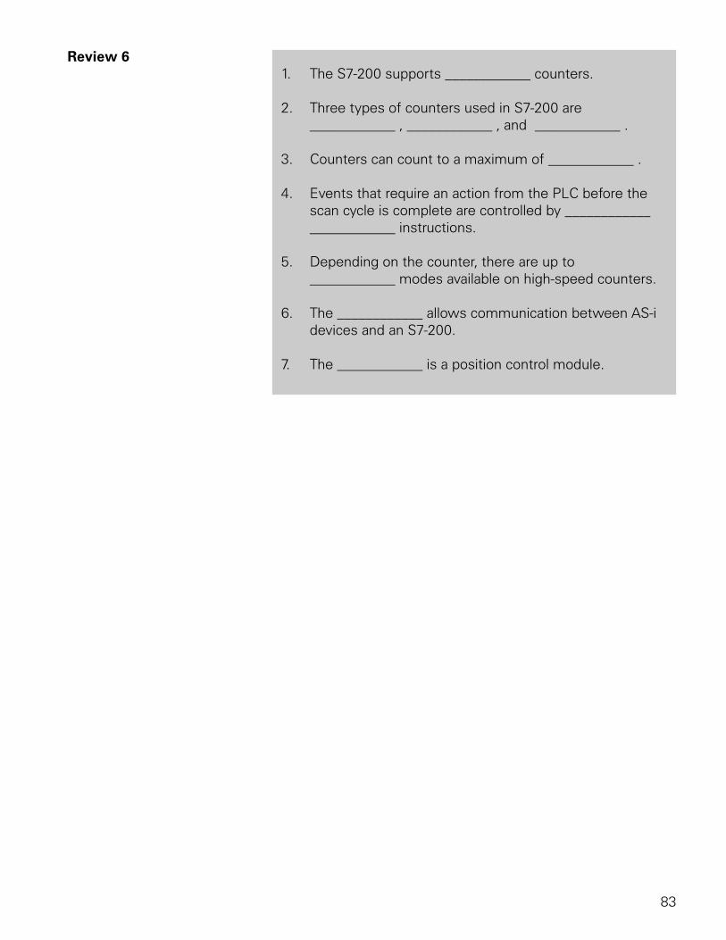
83
Review 61. The S7-200 supports ____________ counters.
2. Three types of counters used in S7-200 are ____________ , ____________ , and ____________ .
3. Counters can count to a maximum of ____________ .
4. Events that require an action from the PLC before the scan cycle is complete are controlled by ____________ ____________ instructions.
5. Depending on the counter, there are up to ____________ modes available on high-speed counters.
6. The ____________ allows communication between AS-i devices and an S7-200.
7. The ____________ is a position control module.
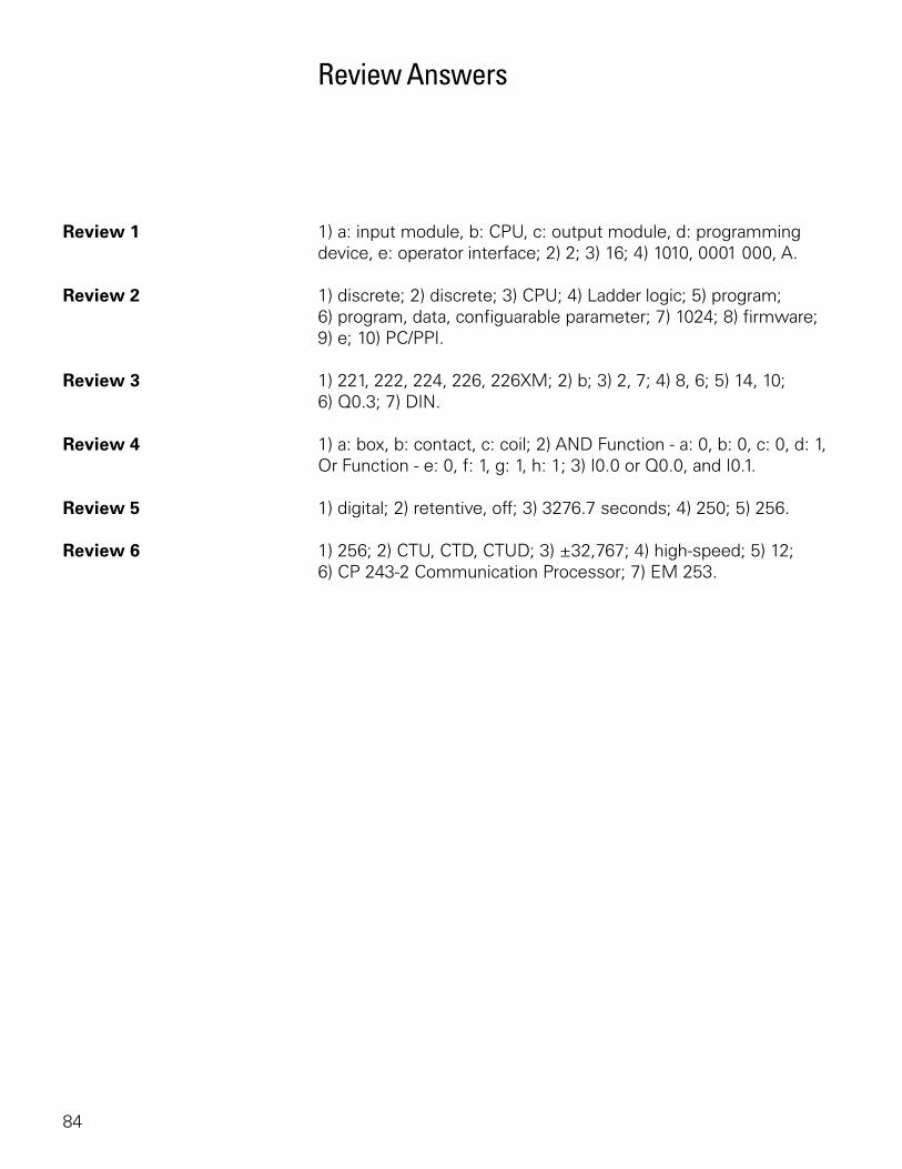
84
Review Answers
Review 1 1) a: input module, b: CPU, c: output module, d: programming device, e: operator interface; 2) 2; 3) 16; 4) 1010, 0001 000, A.
Review 2 1) discrete; 2) discrete; 3) CPU; 4) Ladder logic; 5) program; 6) program, data, configuarable parameter; 7) 1024; 8) firmware; 9) e; 10) PC/PPI.
Review 3 1) 221, 222, 224, 226, 226XM; 2) b; 3) 2, 7; 4) 8, 6; 5) 14, 10; 6) Q0.3; 7) DIN.
Review 4 1) a: box, b: contact, c: coil; 2) AND Function - a: 0, b: 0, c: 0, d: 1, Or Function - e: 0, f: 1, g: 1, h: 1; 3) I0.0 or Q0.0, and I0.1.
Review 5 1) digital; 2) retentive, off; 3) 3276.7 seconds; 4) 250; 5) 256.
Review 6 1) 256; 2) CTU, CTD, CTUD; 3) ±32,767; 4) high-speed; 5) 12; 6) CP 243-2 Communication Processor; 7) EM 253.
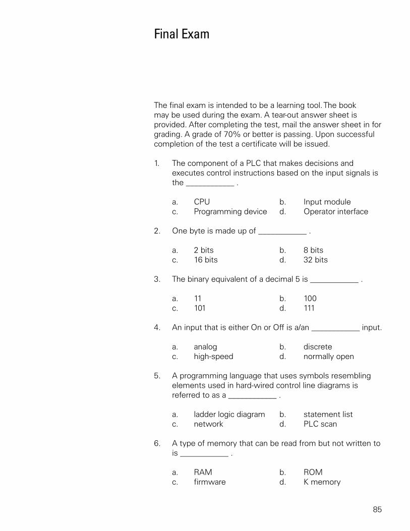
85
Final Exam
The final exam is intended to be a learning tool. The book may be used during the exam. A tear-out answer sheet is provided. After completing the test, mail the answer sheet in for grading. A grade of 70% or better is passing. Upon successful completion of the test a certificate will be issued.
1. The component of a PLC that makes decisions and executes control instructions based on the input signals is the ____________ .
a. CPU b. Input module c. Programming device d. Operator interface
2. One byte is made up of ____________ .
a. 2 bits b. 8 bits c. 16 bits d. 32 bits
3. The binary equivalent of a decimal 5 is ____________ .
a. 11 b. 100 c. 101 d. 111
4. An input that is either On or Off is a/an ____________ input.
a. analog b. discrete c. high-speed d. normally open
5. A programming language that uses symbols resembling elements used in hard-wired control line diagrams is referred to as a ____________ .
a. ladder logic diagram b. statement list c. network d. PLC scan
6. A type of memory that can be read from but not written to is ____________ .
a. RAM b. ROM c. firmware d. K memory
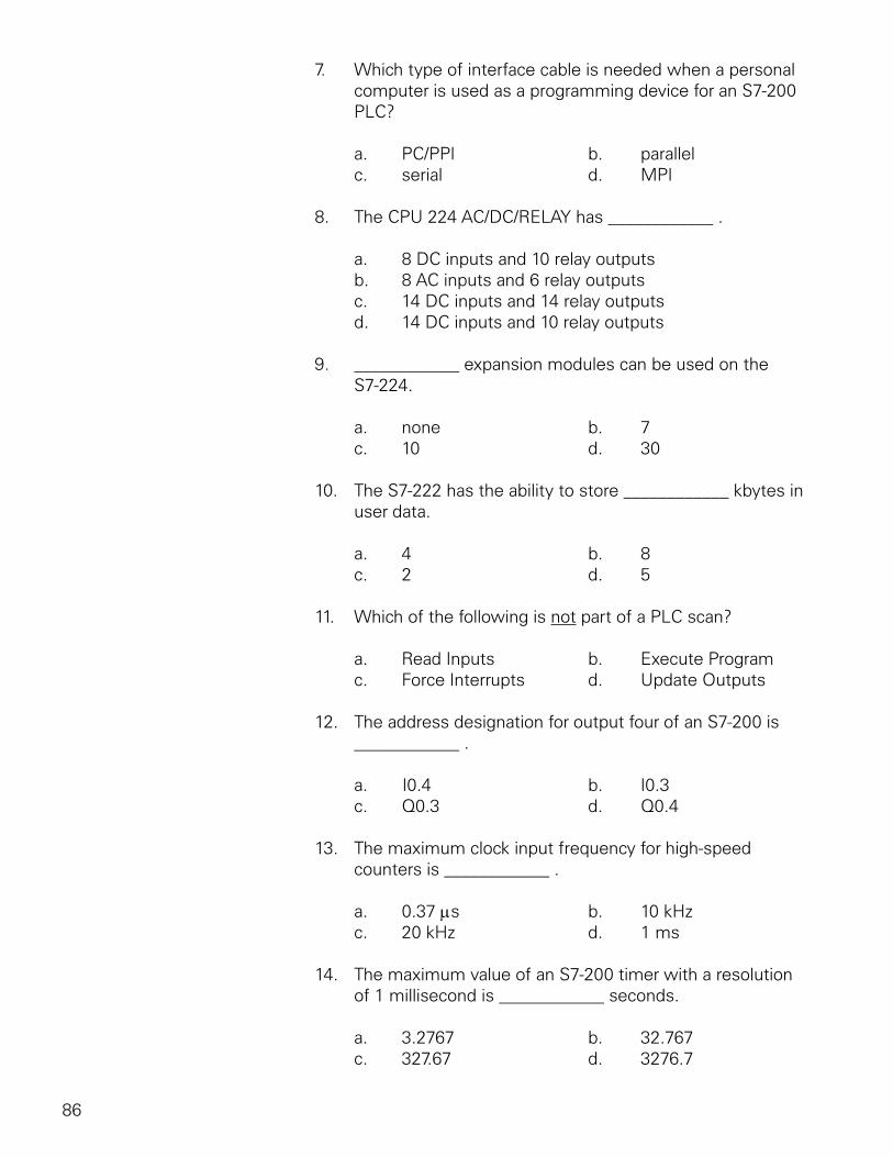
86
7. Which type of interface cable is needed when a personal computer is used as a programming device for an S7-200 PLC?
a. PC/PPI b. parallel c. serial d. MPI
8. The CPU 224 AC/DC/RELAY has ____________ .
a. 8 DC inputs and 10 relay outputs b. 8 AC inputs and 6 relay outputs c. 14 DC inputs and 14 relay outputs d. 14 DC inputs and 10 relay outputs
9. ____________ expansion modules can be used on the S7-224.
a. none b. 7 c. 10 d. 30
10. The S7-222 has the ability to store ____________ kbytes in user data.
a. 4 b. 8 c. 2 d. 5
11. Which of the following is not part of a PLC scan?
a. Read Inputs b. Execute Program c. Force Interrupts d. Update Outputs
12. The address designation for output four of an S7-200 is ____________ .
a. I0.4 b. I0.3 c. Q0.3 d. Q0.4
13. The maximum clock input frequency for high-speed counters is ____________ .
a. 0.37 µs b. 10 kHz c. 20 kHz d. 1 ms
14. The maximum value of an S7-200 timer with a resolution of 1 millisecond is ____________ seconds.
a. 3.2767 b. 32.767 c. 327.67 d. 3276.7
87
15. An S7-200 timer with a time base of 100 ms can count to a maximum value of ____________ seconds.
a. 3.2767 b. 32.767 c. 327.67 d. 3276.7
16. The time base of TON 32 of is ____________ ms.
a. .1 b. 10 c. 1 d. 100
17. The maximum count of an S7-200 up counter is ____________ .
a. 32,767 b. 65,534 c. 98,301 d. 1,000,000
18. A/An ____________ is used to assign a mode to a high-speed counter.
a. toggle switch b. interrupt c. PLC scan d. definition box
19. ____________ instructions allows communication with external devices, such as modems, printers, and computers.
a. Transmit b. Interrupt c. High-speed counters d. High-speed outputs
20. ____________ is used to temporarily override the input or output status in order to test and debug the program.
a. Transmit b. Forcing c. Interrupt d. PLC scan
88
quickSTEP Online Courses
quickSTEP online courses are available at http://www.sea.siemens.com/step.
The quickSTEP training site is divided into three sections: Courses, Downloads, and a Glossary. Online courses include reviews, a final exam, the ability to print a certificate of completion, and the opportunity to register in the Sales & Distributor training database to maintain a record of your accomplishments.
From this site the complete text of all STEP 2000 courses can be downloaded in PDF format. These files contain the most recent changes and updates to the STEP 2000 courses.
A unique feature of the quickSTEP site is our pictorial glossary. The pictorial glossary can be accessed from anywhere within a quickSTEP course. This enables the student to look up an unfamiliar word without leaving the current work area.