centurion na operator manual (002001-...
TRANSCRIPT
CENTURIONrOperator Manual(002001-- )
331020Rev. 02
*331020*
This manual is furnished with each new TENNANT Model Centurionr. It provides necessary operatingand preventive maintenance instructions. Read this manual completely and understand the machinebefore operating or servicing it.
This machine will provide excellent service. However, the best results will be obtained at minimumcosts if:
D The machine is operated with reasonable care.D The machine is maintained regularly -- per the maintenance instructions provided.D The machine is maintained with TENNANT supplied or equivalent parts.
Manual Number -- 331020
Revision: 02
Published: 9--05
CALIFORNIA PROPOSITION 65 WARNING: Engine exhaust from this product containschemicals known to the State of California to cause cancer, birth defects, or otherreproductive harm.
Thermo Sentryr is a United States trademark of Tennant Company.
Streetsmartr is a United States trademark of Tennant Company.
Copyright E 2003, 2004, 2005 TENNANT, Printed in U.S.A.
CONTENTS
1Centurion 331020 (9--05)
CONTENTS
PageSAFETY PRECAUTIONS 4. . . . . . . . . . . . . . . . . . .OPERATION 8. . . . . . . . . . . . . . . . . . . . . . . . . . . . . .
OPERATOR RESPONSIBILITY 8. . . . . . . . . . .MACHINE COMPONENTS 9. . . . . . . . . . . . . . .CONTROL PANEL SYMBOLS 10. . . . . . . . . . .CONTROLS AND INSTRUMENTS 11. . . . . . .
RIGHT HAND STEERINGINSTRUMENT CONSOLE 11. . . . . . . . .
UPPER CONTROL PANELSWITCHES (002001--002999) 12. . . . . .
UPPER CONTROL PANELSWITCHES (003000-- ) 13. . . . . . .
CENTER CONTROL PANELSWITCHES (002001--002999) 14. . . . . .
CENTER CONTROL PANELSWITCHES (003000-- ) 15. . . . . . .
TOUCH PANEL 16. . . . . . . . . . . . . . . . . . . . .OPERATION OF CONTROLS 17. . . . . . . . . . . . . .
IGNITION SWITCH 17. . . . . . . . . . . . . . . . . . . . .PARKING BRAKE KNOB 17. . . . . . . . . . . . . . . .OPERATOR CONTROL SWITCH 17. . . . . . . .REAR AXLE SHIFT CONTROL
SWITCH 18. . . . . . . . . . . . . . . . . . . . . . . . . . .HEATED MIRROR SWITCH (OPTION) 18. . .PUSHBUTTON RANGE SELECTOR 18. . . . .CRUISE CONTROL/THROTTLE LOCK 19. . .PTO KILL SWITCH 19. . . . . . . . . . . . . . . . . . . . .REAR WORK LIGHT SWITCH
(OPTION) 20. . . . . . . . . . . . . . . . . . . . . . . . . .HOPPER WORK LIGHT SWITCH
(OPTION) 20. . . . . . . . . . . . . . . . . . . . . . . . . .RIGHT SIDE INSTRUMENT
CONSOLE 20. . . . . . . . . . . . . . . . . . . . . . . . . .TACHOMETER 21. . . . . . . . . . . . . . . . . . . . . . . .HOURMETER 21. . . . . . . . . . . . . . . . . . . . . . . . .SPEEDOMETER 21. . . . . . . . . . . . . . . . . . . . . . .ENGINE OIL PRESSURE GAUGE 22. . . . . . .ENGINE COOLANT TEMPERATURE
GAUGE 22. . . . . . . . . . . . . . . . . . . . . . . . . . . .VOLTMETER 22. . . . . . . . . . . . . . . . . . . . . . . . . .FUEL LEVEL GAUGE 23. . . . . . . . . . . . . . . . . .AIR BRAKE PRESSURE GAUGE 23. . . . . . . .BRIGHT HEADLIGHTS LIGHT 23. . . . . . . . . . .PREHEAT LIGHT 24. . . . . . . . . . . . . . . . . . . . . .SIGNAL LIGHT 24. . . . . . . . . . . . . . . . . . . . . . . .TOUCH PANEL 24. . . . . . . . . . . . . . . . . . . . . . . .CONTRAST ADJUSTMENT KNOB 24. . . . . . .START UP SCREEN 25. . . . . . . . . . . . . . . . . . . .DISPLAY CLOCK 25. . . . . . . . . . . . . . . . . . . . . .PTO HOURMETER 25. . . . . . . . . . . . . . . . . . . . .BRUSH HOURMETER 26. . . . . . . . . . . . . . . . . .MORE SWITCH 26. . . . . . . . . . . . . . . . . . . . . . . .PTO SWITCH 27. . . . . . . . . . . . . . . . . . . . . . . . . .FAST IDLE 27. . . . . . . . . . . . . . . . . . . . . . . . . . .
PageSWEEP SWITCH 28. . . . . . . . . . . . . . . . . . . . . .SWEEP MODE SWITCH 29. . . . . . . . . . . . . . . .SUPER SWEEP SWITCH 29. . . . . . . . . . . . . . .MAIN BROOM WEAR INDICATOR 29. . . . . . .WATER FLOW SWITCH 30. . . . . . . . . . . . . . . .WATER TANK LEVEL GAUGE 30. . . . . . . . . . .FILTER SHAKER SWITCH 31. . . . . . . . . . . . . .VACUUM FAN SWITCH 32. . . . . . . . . . . . . . . . .LEFT SIDE GUTTER BROOM SWITCH
(OPTION) 32. . . . . . . . . . . . . . . . . . . . . . . . . .RIGHT SIDE GUTTER BROOM
SWITCH 32. . . . . . . . . . . . . . . . . . . . . . . . . . .HOPPER UP SWITCH 33. . . . . . . . . . . . . . . . . .HOPPER DOWN SWITCH 33. . . . . . . . . . . . . .HOPPER DUMP SWITCH 34. . . . . . . . . . . . . . .HOPPER HOME SWITCH 34. . . . . . . . . . . . . . .CONVEYOR IN SWITCH 35. . . . . . . . . . . . . . . .CONVEYOR FORWARD SWITCH 35. . . . . . .CONVEYOR REVERSE SWITCH 35. . . . . . . .CONVEYOR OUT SWITCH 36. . . . . . . . . . . . .CONVEYOR WATER SPRAY SWITCH 36. . .FRONT WATER SPRAY SWITCH 37. . . . . . . .LEFT SIDE WATER SPRAY SWITCH 37. . . . .RIGHT SIDE WATER SPRAY SWITCH 37. . .FUSES 38. . . . . . . . . . . . . . . . . . . . . . . . . . . . . . .LEFT SIDE GUTTER BROOM TILT
SWITCH (OPTION) 39. . . . . . . . . . . . . . . . . .RIGHT SIDE GUTTER BROOM TILT
SWITCH (OPTION) 39. . . . . . . . . . . . . . . . . .GUTTER BROOM SPEED/PRESSURE
ADJUSTMENT (OPTION) 39. . . . . . . . . . . .REVOLVING LIGHT SWITCH
(OPTION) 40. . . . . . . . . . . . . . . . . . . . . . . . . .GUTTER BROOM LIGHT SWITCH
(OPTION) 40. . . . . . . . . . . . . . . . . . . . . . . . . .LATCHES 40. . . . . . . . . . . . . . . . . . . . . . . . . . . . .HOPPER TILT SUPPORT BAR 41. . . . . . . . . .HOPPER LIFT SUPPORT BARS 41. . . . . . . . .
ALARMS 42. . . . . . . . . . . . . . . . . . . . . . . . . . . . . . . . .HOPPER UP ERROR ALARM 42. . . . . . . . . . .CONVEYOR NOT BACK ALARM 42. . . . . . . .CONVEYOR STALL ALARM 42. . . . . . . . . . . . .HOPPER FIRE ALARM 43. . . . . . . . . . . . . . . . .TANK LOW, PUMP OFF ALARM 43. . . . . . . . .REDUCE ENGINE RPM ALARM 43. . . . . . . . .CHECK HYDRAULIC FILTER ALARM 44. . . .ACTIVATE PARK BRAKE ALARM 44. . . . . . . .ERROR--BROOMS DOWN ALARM 44. . . . . . .SHAKE FILTER ALARM 45. . . . . . . . . . . . . . . . .OVERSPEED ENGINE ALARM 45. . . . . . . . . .RELEASE E--STOP ALARM 45. . . . . . . . . . . . .MACHINE NOT LEVEL ALARM 46. . . . . . . . . .HYDRAULIC FLUID LOW ALARM
(OPTION) 46. . . . . . . . . . . . . . . . . . . . . . . . . .
CONTENTS
Centurion 331020 (9--05)2
PageHOW THE MACHINE WORKS 47. . . . . . . . . . . . . .PRE AND POST OPERATION
CHECKLIST 48. . . . . . . . . . . . . . . . . . . . . . . . . . .STARTING THE MACHINE 49. . . . . . . . . . . . . . . . .SWEEPING AND BRUSH INFORMATION 51. . .
SWEEP MODES 52. . . . . . . . . . . . . . . . . . . . . . .SETTING THE CUSTOM MODE 54. . . . . . . . .FILLING THE WATER TANK 55. . . . . . . . . . . . .SWEEPING 57. . . . . . . . . . . . . . . . . . . . . . . . . . .STOP SWEEPING 59. . . . . . . . . . . . . . . . . . . . .EMPTYING THE HOPPER 60. . . . . . . . . . . . . .STOPPING THE MACHINE 62. . . . . . . . . . . . .OPERATION ON INCLINES 63. . . . . . . . . . . . .ENGAGING HOPPER TILT SUPPORT
BAR 64. . . . . . . . . . . . . . . . . . . . . . . . . . . . . . .DISENGAGING HOPPER TILT
SUPPORT BAR 66. . . . . . . . . . . . . . . . . . . . .ENGAGING HOPPER LIFT SUPPORT
BARS 68. . . . . . . . . . . . . . . . . . . . . . . . . . . . . .DISENGAGING HOPPER LIFT
SUPPORT BARS 70. . . . . . . . . . . . . . . . . . . .MACHINE TROUBLESHOOTING 72. . . . . . . .MACHINE TROUBLESHOOTING 73. . . . . . . .
MAINTENANCE 74. . . . . . . . . . . . . . . . . . . . . . . . . .MAINTENANCE CHART 75. . . . . . . . . . . . . . . .LUBRICATION 77. . . . . . . . . . . . . . . . . . . . . . . . .
HOPPER LIFT/TILT 77. . . . . . . . . . . . . . . . . .ENGINE 77. . . . . . . . . . . . . . . . . . . . . . . . . . .GUTTER BROOM SUPPORT
RODS 78. . . . . . . . . . . . . . . . . . . . . . . . . . .GUTTER BROOM SUPPORT
ARMS 78. . . . . . . . . . . . . . . . . . . . . . . . . . .GUTTER BROOM PIVOT 78. . . . . . . . . . . .DUST CONTROL SKIRT CYLINDER
(OPTION) 79. . . . . . . . . . . . . . . . . . . . . . .DUST CONTROL SKIRT PIVOTS
(OPTION) 79. . . . . . . . . . . . . . . . . . . . . . .DUST CONTROL BUMPER PIVOTS
(OPTION) 79. . . . . . . . . . . . . . . . . . . . . . .MAIN BRUSH SUPPORT ARMS 80. . . . . .MAIN BRUSH IDLER BEARING 80. . . . . . .DRAG SHOE PIVOT 80. . . . . . . . . . . . . . . . .MAIN BRUSH LIFT CYLINDER 81. . . . . . .DRAG SHOE LIFT CYLINDER 81. . . . . . . .MAIN BRUSH AND DRAG SHOE
CYLINDERS 81. . . . . . . . . . . . . . . . . . . . .CONVEYOR BEARINGS 82. . . . . . . . . . . . .CONVEYOR LIFT PIVOTS 82. . . . . . . . . . .CONVEYOR LIFT CYLINDERS 82. . . . . . .CONVEYOR TILT CYLINDER 83. . . . . . . . .DRY DUST CONTROL SKIRT WING
PIVOTS (OPTION) 83. . . . . . . . . . . . . . .PROPULSION SHAFT SLIP JOINT 83. . . .AUTO LUBE (OPTION) 84. . . . . . . . . . . . . .
PageHYDRAULICS 85. . . . . . . . . . . . . . . . . . . . . . . . .
HYDRAULIC FLUID RESERVOIR 85. . . . .HYDRAULIC FLUID 86. . . . . . . . . . . . . . . . .HYDRAULIC PUMP LOAD SENSE
FILTERS 87. . . . . . . . . . . . . . . . . . . . . . . .CHECKING THE LOAD SENSE
FILTERS 87. . . . . . . . . . . . . . . . . . . . . . . .HYDRAULIC FLUID FILTER 88. . . . . . . . . .HYDRAULIC COOLING SYSTEM 88. . . . .HYDRAULIC HOSES 88. . . . . . . . . . . . . . . .
ENGINE 89. . . . . . . . . . . . . . . . . . . . . . . . . . . . . .ENGINE 89. . . . . . . . . . . . . . . . . . . . . . . . . . .AIR FILTER RESTRICTION
INDICATOR 89. . . . . . . . . . . . . . . . . . . . . .RADIATOR 89. . . . . . . . . . . . . . . . . . . . . . . . .
TRANSMISSION 90. . . . . . . . . . . . . . . . . . . . . . .TRANSMISSION ACCESS 90. . . . . . . . . . .
REMOVING DRY DUSTCONTROL ASSEMBLY 90. . . . . . . . .
WET DUST CONTROL SYSTEM 94. . . . . . . . .WATER TANK 94. . . . . . . . . . . . . . . . . . . . . . .WATER PUMP 94. . . . . . . . . . . . . . . . . . . . . .WATER FILTER 95. . . . . . . . . . . . . . . . . . . . .WATER HOSES 95. . . . . . . . . . . . . . . . . . . . .SPRAY NOZZLES 95. . . . . . . . . . . . . . . . . . .
DEBRIS HOPPER 96. . . . . . . . . . . . . . . . . . . . . .THERMO SENTRY 96. . . . . . . . . . . . . . . . . .HOPPER DUST FILTER 96. . . . . . . . . . . . . .RINSING THE HOPPER DUST
FILTER 97. . . . . . . . . . . . . . . . . . . . . . . . . .TO REMOVE OR REPLACE
HOPPER DUST FILTER 98. . . . . . . . . . .CONVEYOR 100. . . . . . . . . . . . . . . . . . . . . . . . .
ADJUSTING THE CONVEYORHEIGHT 101. . . . . . . . . . . . . . . . . . . . . . .
FLUSHING THE CONVEYORBELT 102. . . . . . . . . . . . . . . . . . . . . . . . . .
ADJUSTING THE CONVEYOR BELTTRACKING 103. . . . . . . . . . . . . . . . . . . .
TO REPLACE THE CONVEYORBELT 105. . . . . . . . . . . . . . . . . . . . . . . . .
BRUSHES 108. . . . . . . . . . . . . . . . . . . . . . . . . . .MAIN BRUSH 108. . . . . . . . . . . . . . . . . . . . .TO REPLACE THE MAIN BRUSH 108. . .TO CHECK AND ADJUST MAIN
BRUSH PATTERN 112. . . . . . . . . . . . . . .GUTTER BROOM(S) 113. . . . . . . . . . . . . . .TO REPLACE THE GUTTER
BROOM(S) 113. . . . . . . . . . . . . . . . . . . . .TO CHECK AND ADJUST THE
GUTTER BROOM PATTERN 114. . . . .MAIN BRUSH AND DRAG SHOE CABLE
AND ARM STOPS 116. . . . . . . . . . . . . . . . . .TO CHECK MAIN BRUSH ARM
STOPS 116. . . . . . . . . . . . . . . . . . . . . .
CONTENTS
3Centurion 331020 (9--05)
PageTO ADJUST MAIN BRUSH ARM
STOPS 117. . . . . . . . . . . . . . . . . . . . . .TO CHECK AND ADJUST DRAG
SHOE CABLES 118. . . . . . . . . . . . . .TO CHECK AND ADJUST DRAG
SHOE ARM STOPS 119. . . . . . . . . . .SKIRTS AND SEALS 120. . . . . . . . . . . . . . . . .
BRUSH COMPARTMENT SIDESKIRT 120. . . . . . . . . . . . . . . . . . . . . . . . .
BRUSH COMPARTMENT REARSKIRT 120. . . . . . . . . . . . . . . . . . . . . . . . .
TOP CONVEYOR SKIRTS 120. . . . . . . . .BOTTOM CONVEYOR SKIRTS 121. . . . .HOPPER CHUTE DOOR SKIRT 121. . . .HOPPER CHUTE DOOR SEALS 121. . . .HOPPER ACCESS DOOR SEAL 122. . . .HOPPER FILTER COVER SEAL 122. . . .VACUUM DUCT SEALS
(OPTION) 122. . . . . . . . . . . . . . . . . . . . .ACCESS PANEL DUST SKIRTS
(OPTION) 123. . . . . . . . . . . . . . . . . . . . .FRONT DRY DUST CONTROL
SKIRTS (OPTION) 123. . . . . . . . . . . . . .CENTER DRY DUST CONTROL
SKIRT (OPTION) 123. . . . . . . . . . . . . . .REAR DRY DUST CONTROL
SKIRTS (OPTION) 124. . . . . . . . . . . . . .DRY DUST CONTROL WING
SKIRTS (OPTION) 124. . . . . . . . . . . . . .DRY DUST CONTROL GUTTER
BROOM SKIRT(S) (OPTION) 124. . . .MAIN BRUSH DRAG SHOES 125. . . . . . .MACHINE JACKING 126. . . . . . . . . . . . . . .STORING MACHINE 126. . . . . . . . . . . . . .
FREEZE PROTECTION FOR WETDUST CONTROL SYSTEM 126. . .
TRANSPORTING THE MACHINE 128. . .SPECIFICATIONS 129. . . . . . . . . . . . . . . . . . . . . .
GENERAL MACHINE DIMENSIONS/CAPACITIES 129. . . . . . . . . . . . . . . . . . . . . .
GENERAL MACHINEPERFORMANCE 130. . . . . . . . . . . . . . . . . .
POWER TYPE 130. . . . . . . . . . . . . . . . . . . . . . .TRANSMISSION FLUID 130. . . . . . . . . . . . . . .STEERING 130. . . . . . . . . . . . . . . . . . . . . . . . . .HYDRAULIC SYSTEM 131. . . . . . . . . . . . . . . .BRAKING SYSTEM 131. . . . . . . . . . . . . . . . . .MACHINE DIMENSIONS 131. . . . . . . . . . . . . .
INDEX 133. . . . . . . . . . . . . . . . . . . . . . . . . . . . . . . . .
SAFETY PRECAUTIONS
Centurion 331020 (11--03)4
SAFETY PRECAUTIONS
The following precautions are used throughoutthis manual as indicated in their description:
WARNING: To warn of hazards orunsafe practices which could result insevere personal injury or death.
FOR SAFETY: To identify actions whichmust be followed for safe operation ofequipment.
The machine is suited to sweep disposabledebris. Do not use the machine other thandescribed in this Operator Manual.
The following information signals potentiallydangerous conditions to the operator orequipment:
WARNING: Burn Hazard. Hot Surface.Do Not Touch.
WARNING: Raised hopper may fall.Engage hopper support bar.
WARNING: Tilted hopper may fall.Engage hopper support bar.
WARNING: Brush linkage pinch points.Stay clear when linkage is moving.
WARNING: Side brush can move. Donot step on side brush.
WARNING: High dump verticalclearance. Stay clear of overheadobstructions and power lines.
WARNING: Conveyor throws debris.Conveyor pinch point. Stay clear whenin operation.
WARNING: Flammable materials cancause explosion or fire. Do not useflammable materials in tank. Only usewater.
WARNING: Lift arm pinch point. Stayclear of hopper lift arms.
WARNING: Loss Of Steering ControlCan Result. Stop Machine And Place InNeutral Before Switching OperatorControl.
WARNING: Engine emits toxic gases.Severe respiratory damage orasphyxiation can result. Provideadequate ventilation. Consult with yourregulatory agency for exposure limits.Keep engine properly tuned.
WARNING: Rotating PTO Shaft.Never Get Under Machine If EngineIs Running.
FOR SAFETY:1. Do not operate machine:
-- Unless trained and authorized. Thismachine requires an updatedCommercial Drivers License foroperation.
-- Unless all TENNANT and truckmanuals are read and understood.
-- In flammable or explosive areas.
2. Before starting machine:-- Check for fuel leaks.-- Keep sparks and open flame awayfrom refueling area.
-- Make sure all safety devices are inplace and operate properly.
-- Check brakes and steering for properoperation.
3. When using machine:-- Use brakes to stop machine.-- Go slow on inclines and slipperysurfaces.
-- Use care when reversing machine.-- Do not move machine when hopper israised.
-- Only dump the hopper on a levelsurface.
-- Make sure adequate clearance isavailable before raising hopper.
-- Do not carry riders on machine.-- Always follow safety and traffic rules.-- Report machine damage or faultyoperation immediately.
4. Before leaving or servicing machine:-- Stop on level surface.-- Set parking brake.-- Turn off machine and remove key.

SAFETY PRECAUTIONS
5Centurion 331020 (11--03)
5. When servicing TENNANT sweepingcomponents:-- Avoid moving parts. do not wear loosejackets, shirts, or sleeves.
-- Block machine tires before jackingmachine up.
-- Jack machine up at designatedlocations only. Block machine up withjack stands.
-- Use hoist or jack that will support theweight of the machine.
-- Wear eye and ear protection whenusing pressurized air or water.
-- Disconnect battery connections beforeworking on machine.
-- Avoid contact with battery acid.-- Keep flames and sparks away fromfuel system service area. Keep areawell ventilated.
-- Use cardboard to locate leakinghydraulic fluid under pressure.
-- Use Tennant supplied or approvedreplacement parts.
6. When loading/unloading machineonto/off truck or trailer:-- Turn off machine.-- Use truck or trailer that will supportthe weight of the machine.
-- Set parking brake after machine isloaded.
-- Block machine tires.-- Tie machine down to truck or trailer.
SAFETY PRECAUTIONS
Centurion 331020 (11--03)6
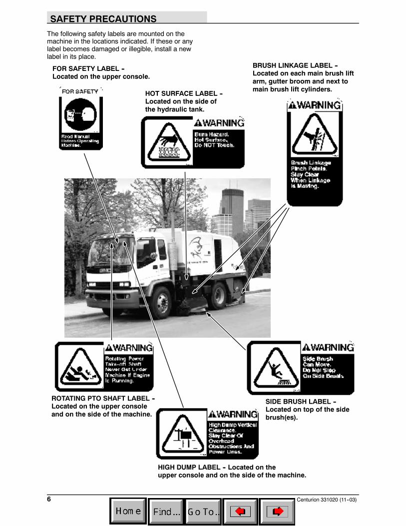
The following safety labels are mounted on themachine in the locations indicated. If these or anylabel becomes damaged or illegible, install a newlabel in its place.
BRUSH LINKAGE LABEL --Located on each main brush liftarm, gutter broom and next tomain brush lift cylinders.
FOR SAFETY LABEL --Located on the upper console.
SIDE BRUSH LABEL --Located on top of the sidebrush(es).
HOT SURFACE LABEL --Located on the side ofthe hydraulic tank.
HIGH DUMP LABEL -- Located on theupper console and on the side of the machine.
ROTATING PTO SHAFT LABEL --Located on the upper consoleand on the side of the machine.
SAFETY PRECAUTIONS
7Centurion 331020 (11--03)
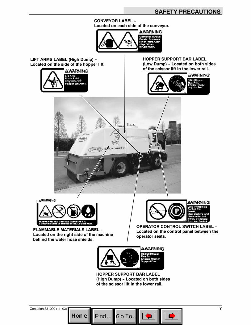
HOPPER SUPPORT BAR LABEL(High Dump) -- Located on both sidesof the scissor lift in the lower rail.
CONVEYOR LABEL --Located on each side of the conveyor.
FLAMMABLE MATERIALS LABEL --Located on the right side of the machinebehind the water hose shields.
LIFT ARMS LABEL (High Dump) --Located on the side of the hopper lift.
HOPPER SUPPORT BAR LABEL(Low Dump) -- Located on both sidesof the scissor lift in the lower rail.
OPERATOR CONTROL SWITCH LABEL --Located on the control panel between theoperator seats.
OPERATION
Centurion 331020 (11--03)8
OPERATION
OPERATOR RESPONSIBILITY
- The operator is responsible for conductingdaily maintenance and checkups andkeeping the machine in good workingcondition. The operator must inform theservice mechanic or supervisor when therequired maintenance intervals occur asstated in the MAINTENANCE section of thismanual.
- This machine requires a Commercial DriversLicense for operation. Keep updated with alllicenses and machine operation training.
- Read this manual carefully before operatingthis machine. Review all of the trainingmaterials supplied with the machine.
FOR SAFETY: Do not operate machine,unless operation manual is read andunderstood.
- Check the machine for shipping damage.Check to make sure machine is completeper shipping instructions.
- Keep the machine regularly maintained byfollowing the maintenance information in thismanual and all other truck manuals suppliedwith the machine. We recommend takingadvantage of a regularly scheduled servicecontract from your TENNANTrepresentative.
- Order parts and supplies directly from anauthorized TENNANT representative. Usethe parts manual provided when orderingparts.
- The model CENTURIONt has a GVWR of14,850 kg (33,000 lb), 4536 kg (12,000 lb)front axle and 9450 kg (21,000 lb) rear axle.Operate only on surfaces capable ofsupporting this weight.
07324
OPERATION
9Centurion 331020 (11--03)
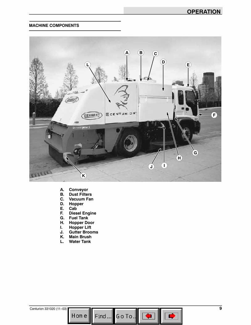
MACHINE COMPONENTS
DE
F
H
J
K
L
A B C
G
I
A. ConveyorB. Dust FiltersC. Vacuum FanD. HopperE. CabF. Diesel EngineG. Fuel TankH. Hopper DoorI. Hopper LiftJ. Gutter BroomsK. Main BrushL. Water Tank

OPERATION
Centurion 331020 (11--03)10
CONTROL PANEL SYMBOLS
These symbols identify controls and displays onthe machine:
Right Side Gutter Broom Light Bright Headlights
Left Side Gutter Broom Light Signal Lights
Revolving Light Air Inlet Heater (Preheat)
Fuel
OPERATION
11Centurion 331020 (11--03)
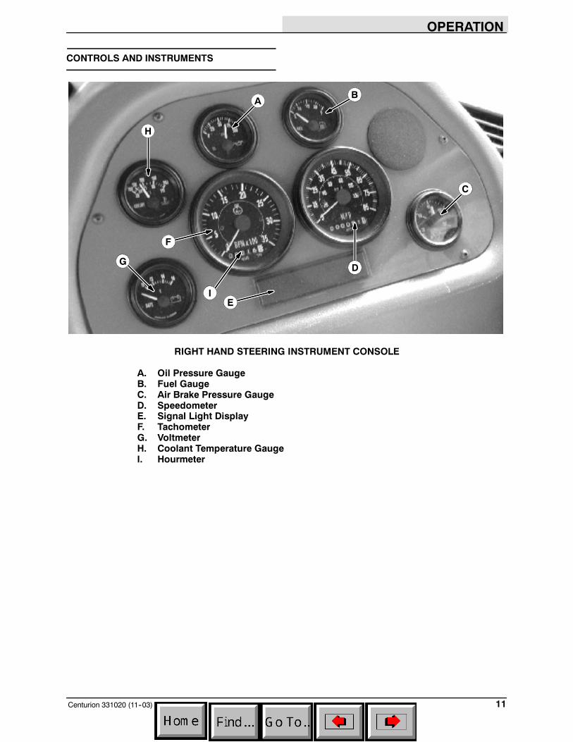
CONTROLS AND INSTRUMENTS
H
AB
D
E
C
F
G
I
RIGHT HAND STEERING INSTRUMENT CONSOLE
A. Oil Pressure GaugeB. Fuel GaugeC. Air Brake Pressure GaugeD. SpeedometerE. Signal Light DisplayF. TachometerG. VoltmeterH. Coolant Temperature GaugeI. Hourmeter

OPERATION
Centurion 331020 (9--05)12
DC
BA
EF
GH
I
UPPER CONTROL PANEL SWITCHES (002001--002999)
A. OpenB. Rear Work LightC. Hopper Work LightD. PTO (Power Take Off) Kill SwitchE. Left Side Gutter Broom Tilt Switch (Option)F. OpenG. Revolving Light Switch (Option)H. Gutter Broom Work LightsI. Right Side Gutter Broom Tilt Switch (Option)
OPERATION
13Centurion 331020 (9--05)
DA B C
E
F
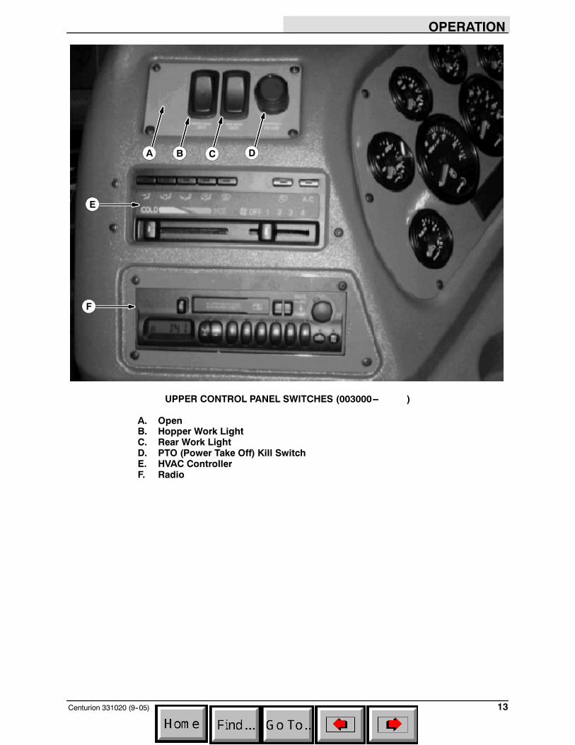
UPPER CONTROL PANEL SWITCHES (003000-- )
A. OpenB. Hopper Work LightC. Rear Work LightD. PTO (Power Take Off) Kill SwitchE. HVAC ControllerF. Radio
OPERATION
Centurion 331020 (9--05)14
D
A B C
FG
E
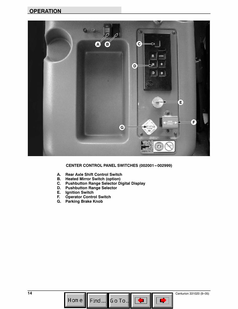
CENTER CONTROL PANEL SWITCHES (002001--002999)
A. Rear Axle Shift Control SwitchB. Heated Mirror Switch (option)C. Pushbutton Range Selector Digital DisplayD. Pushbutton Range SelectorE. Ignition SwitchF. Operator Control SwitchG. Parking Brake Knob
OPERATION
15Centurion 331020 (9--05)
A
D
C
B
E
F I J K
M
N QPO
G H L
R
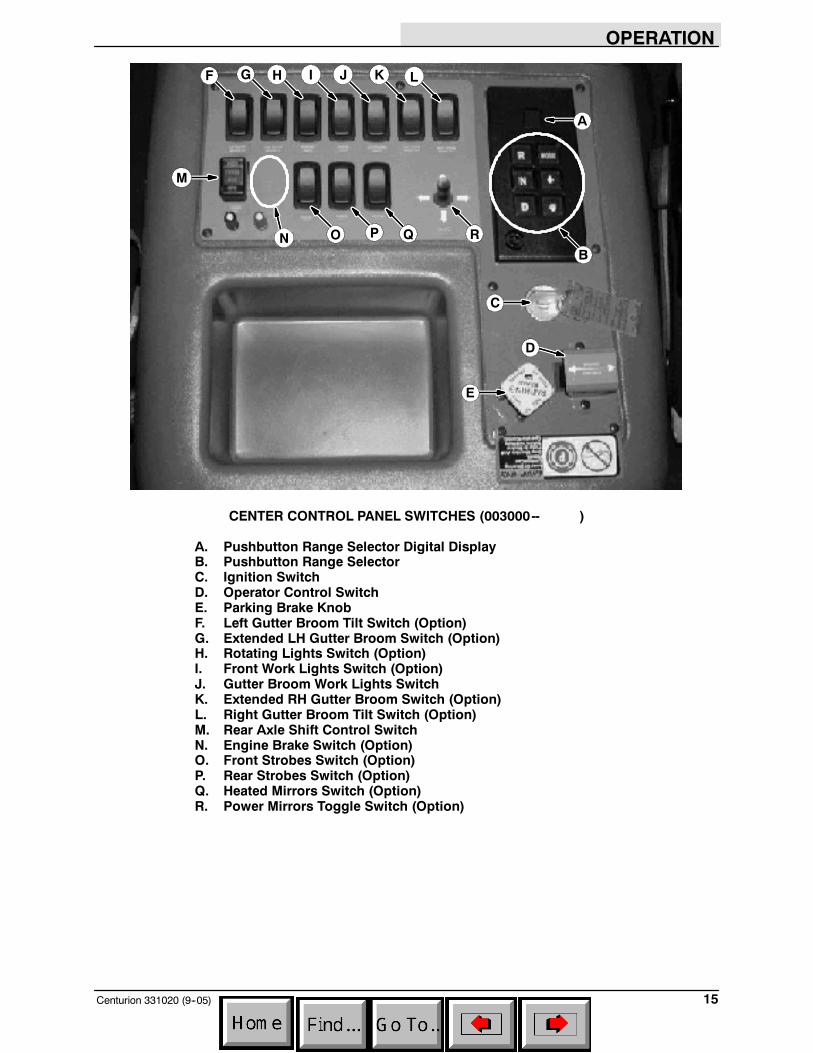
CENTER CONTROL PANEL SWITCHES (003000-- )
A. Pushbutton Range Selector Digital DisplayB. Pushbutton Range SelectorC. Ignition SwitchD. Operator Control SwitchE. Parking Brake KnobF. Left Gutter Broom Tilt Switch (Option)G. Extended LH Gutter Broom Switch (Option)H. Rotating Lights Switch (Option)I. Front Work Lights Switch (Option)J. Gutter Broom Work Lights SwitchK. Extended RH Gutter Broom Switch (Option)L. Right Gutter Broom Tilt Switch (Option)M. Rear Axle Shift Control SwitchN. Engine Brake Switch (Option)O. Front Strobes Switch (Option)P. Rear Strobes Switch (Option)Q. Heated Mirrors Switch (Option)R. Power Mirrors Toggle Switch (Option)

OPERATION
Centurion 331020 (7--04)16
A
B
C
K
F
DG
HI
J
B
B
B
B
B
E
TOUCH PANEL
A. Display ScreenB. Multi--Function Switches (6)C. Front Spray Nozzle SwitchD. Right Side Gutter Broom Spray Nozzle SwitchE. Conveyor Spray Nozzle SwitchF. Left Side Gutter Broom Spray Nozzle Switch (Option)G. Right Side Gutter Broom SwitchH. Left Side Gutter Broom Switch (Option)I. PTO (Power Take Off) SwitchJ. Sweep SwitchK. Contrast Adjustment Knob
OPERATION
17Centurion 331020 (7--04)
OPERATION OF CONTROLS
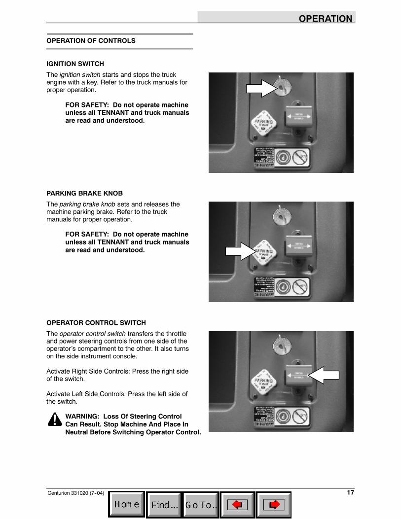
IGNITION SWITCH
The ignition switch starts and stops the truckengine with a key. Refer to the truck manuals forproper operation.
FOR SAFETY: Do not operate machineunless all TENNANT and truck manualsare read and understood.
PARKING BRAKE KNOB
The parking brake knob sets and releases themachine parking brake. Refer to the truckmanuals for proper operation.
FOR SAFETY: Do not operate machineunless all TENNANT and truck manualsare read and understood.
OPERATOR CONTROL SWITCH
The operator control switch transfers the throttleand power steering controls from one side of theoperator’s compartment to the other. It also turnson the side instrument console.
Activate Right Side Controls: Press the right sideof the switch.
Activate Left Side Controls: Press the left side ofthe switch.
WARNING: Loss Of Steering ControlCan Result. Stop Machine And Place InNeutral Before Switching Operator Control.

OPERATION
Centurion 331020 (9--05)18
REAR AXLE SHIFT CONTROL SWITCH
The rear axle shift control switch controls the rearaxle operating range. Refer to the truck manualsfor proper operation.
FOR SAFETY: Do not operate machineunless all TENNANT and truck operationmanuals are read and understood.
NOTE: For best slow speed sweeping results,drive the machine in D1 (first gear) with the rearaxle in low range.
NOTE: To engage the low range on the rearaxle, park the machine on level ground, andselect low range.
HEATED MIRROR SWITCH (OPTION)
The heated mirror switch controls the heatedmirror option. Refer to the truck manuals forproper operation.
FOR SAFETY: Do not operate machineunless all TENNANT and truck operationmanuals are read and understood.
PUSHBUTTON RANGE SELECTOR
The pushbutton range selector is used to selectthe different operating gears and D (Drive)ranges. The digital display shows what gear oroperating range the truck is in. Refer to the truckmanuals for proper operation.
FOR SAFETY: Do not operate machineunless all TENNANT and truck operationmanuals are read and understood.
NOTE: For best slow speed sweeping results,drive the machine in D1 (first gear) with the rearaxle in low range.
NOTE: To engage the low range on the rear axle,park the machine on level ground, and select lowrange.
OPERATION
19Centurion 331020 (11--03)
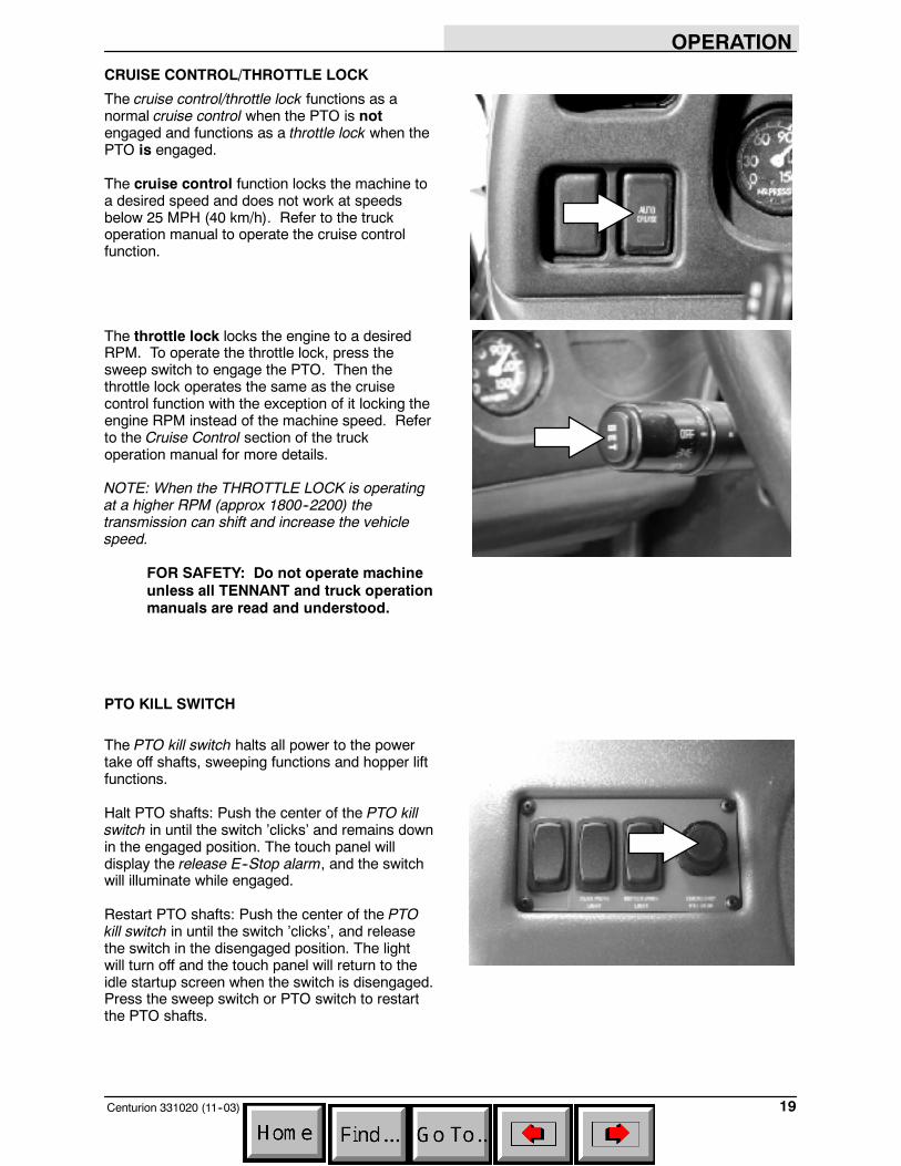
CRUISE CONTROL/THROTTLE LOCK
The cruise control/throttle lock functions as anormal cruise control when the PTO is notengaged and functions as a throttle lock when thePTO is engaged.
The cruise control function locks the machine toa desired speed and does not work at speedsbelow 25 MPH (40 km/h). Refer to the truckoperation manual to operate the cruise controlfunction.
The throttle lock locks the engine to a desiredRPM. To operate the throttle lock, press thesweep switch to engage the PTO. Then thethrottle lock operates the same as the cruisecontrol function with the exception of it locking theengine RPM instead of the machine speed. Referto the Cruise Control section of the truckoperation manual for more details.
NOTE: When the THROTTLE LOCK is operatingat a higher RPM (approx 1800--2200) thetransmission can shift and increase the vehiclespeed.
FOR SAFETY: Do not operate machineunless all TENNANT and truck operationmanuals are read and understood.
PTO KILL SWITCH
The PTO kill switch halts all power to the powertake off shafts, sweeping functions and hopper liftfunctions.
Halt PTO shafts: Push the center of the PTO killswitch in until the switch ’clicks’ and remains downin the engaged position. The touch panel willdisplay the release E--Stop alarm, and the switchwill illuminate while engaged.
Restart PTO shafts: Push the center of the PTOkill switch in until the switch ’clicks’, and releasethe switch in the disengaged position. The lightwill turn off and the touch panel will return to theidle startup screen when the switch is disengaged.Press the sweep switch or PTO switch to restartthe PTO shafts.
OPERATION
Centurion 331020 (11--03)20
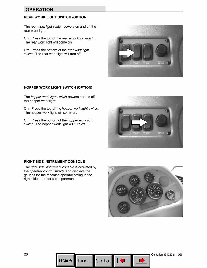
REAR WORK LIGHT SWITCH (OPTION)
The rear work light switch powers on and off therear work light.
On: Press the top of the rear work light switch.The rear work light will come on.
Off: Press the bottom of the rear work lightswitch. The rear work light will turn off.
HOPPER WORK LIGHT SWITCH (OPTION)
The hopper work light switch powers on and offthe hopper work light.
On: Press the top of the hopper work light switch.The hopper work light will come on.
Off: Press the bottom of the hopper work lightswitch. The hopper work light will turn off.
RIGHT SIDE INSTRUMENT CONSOLE
The right side instrument console is activated bythe operator control switch, and displays thegauges for the machine operator sitting in theright side operator’s compartment.
OPERATION
21Centurion 331020 (11--03)
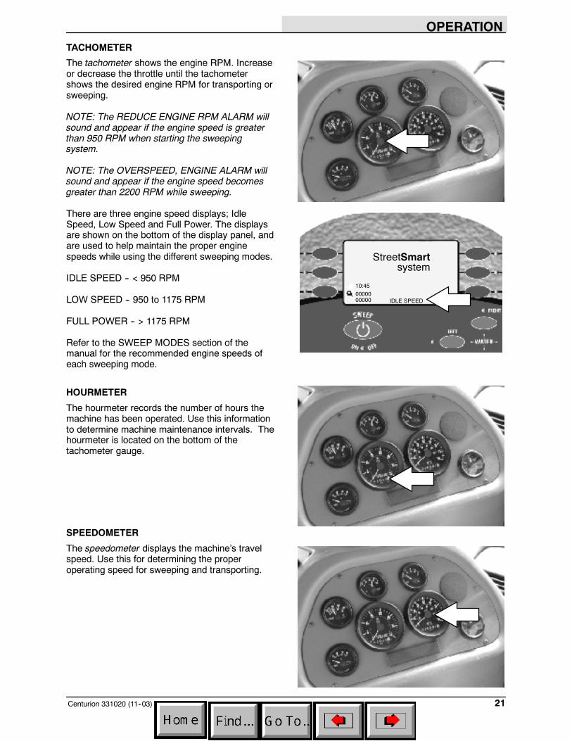
TACHOMETER
The tachometer shows the engine RPM. Increaseor decrease the throttle until the tachometershows the desired engine RPM for transporting orsweeping.
NOTE: The REDUCE ENGINE RPM ALARM willsound and appear if the engine speed is greaterthan 950 RPM when starting the sweepingsystem.
NOTE: The OVERSPEED, ENGINE ALARM willsound and appear if the engine speed becomesgreater than 2200 RPM while sweeping.
There are three engine speed displays; IdleSpeed, Low Speed and Full Power. The displaysare shown on the bottom of the display panel, andare used to help maintain the proper enginespeeds while using the different sweeping modes.
IDLE SPEED -- < 950 RPM
LOW SPEED -- 950 to 1175 RPM
FULL POWER -- > 1175 RPM
Refer to the SWEEP MODES section of themanual for the recommended engine speeds ofeach sweeping mode.
HOURMETER
The hourmeter records the number of hours themachine has been operated. Use this informationto determine machine maintenance intervals. Thehourmeter is located on the bottom of thetachometer gauge.
SPEEDOMETER
The speedometer displays the machine’s travelspeed. Use this for determining the properoperating speed for sweeping and transporting.
MORE
StreetSmartsystem
0000000000
10:45
IDLE SPEED
OPERATION
Centurion 331020 (11--03)22
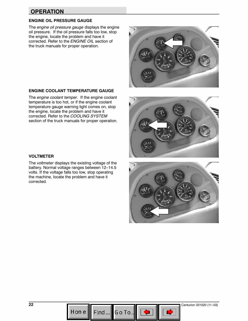
ENGINE OIL PRESSURE GAUGE
The engine oil pressure gauge displays the engineoil pressure. If the oil pressure falls too low, stopthe engine, locate the problem and have itcorrected. Refer to the ENGINE OIL section ofthe truck manuals for proper operation.
ENGINE COOLANT TEMPERATURE GAUGE
The engine coolant temper. If the engine coolanttemperature is too hot, or if the engine coolanttemperature gauge warning light comes on, stopthe engine, locate the problem and have itcorrected. Refer to the COOLING SYSTEMsection of the truck manuals for proper operation.
VOLTMETER
The voltmeter displays the existing voltage of thebattery. Normal voltage ranges between 12--14.5volts. If the voltage falls too low, stop operatingthe machine, locate the problem and have itcorrected.
OPERATION
23Centurion 331020 (7--04)
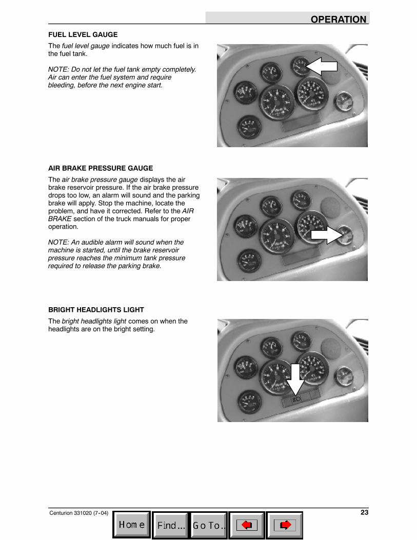
FUEL LEVEL GAUGE
The fuel level gauge indicates how much fuel is inthe fuel tank.
NOTE: Do not let the fuel tank empty completely.Air can enter the fuel system and requirebleeding, before the next engine start.
AIR BRAKE PRESSURE GAUGE
The air brake pressure gauge displays the airbrake reservoir pressure. If the air brake pressuredrops too low, an alarm will sound and the parkingbrake will apply. Stop the machine, locate theproblem, and have it corrected. Refer to the AIRBRAKE section of the truck manuals for properoperation.
NOTE: An audible alarm will sound when themachine is started, until the brake reservoirpressure reaches the minimum tank pressurerequired to release the parking brake.
BRIGHT HEADLIGHTS LIGHT
The bright headlights light comes on when theheadlights are on the bright setting.
OPERATION
Centurion 331020 (7--04)24
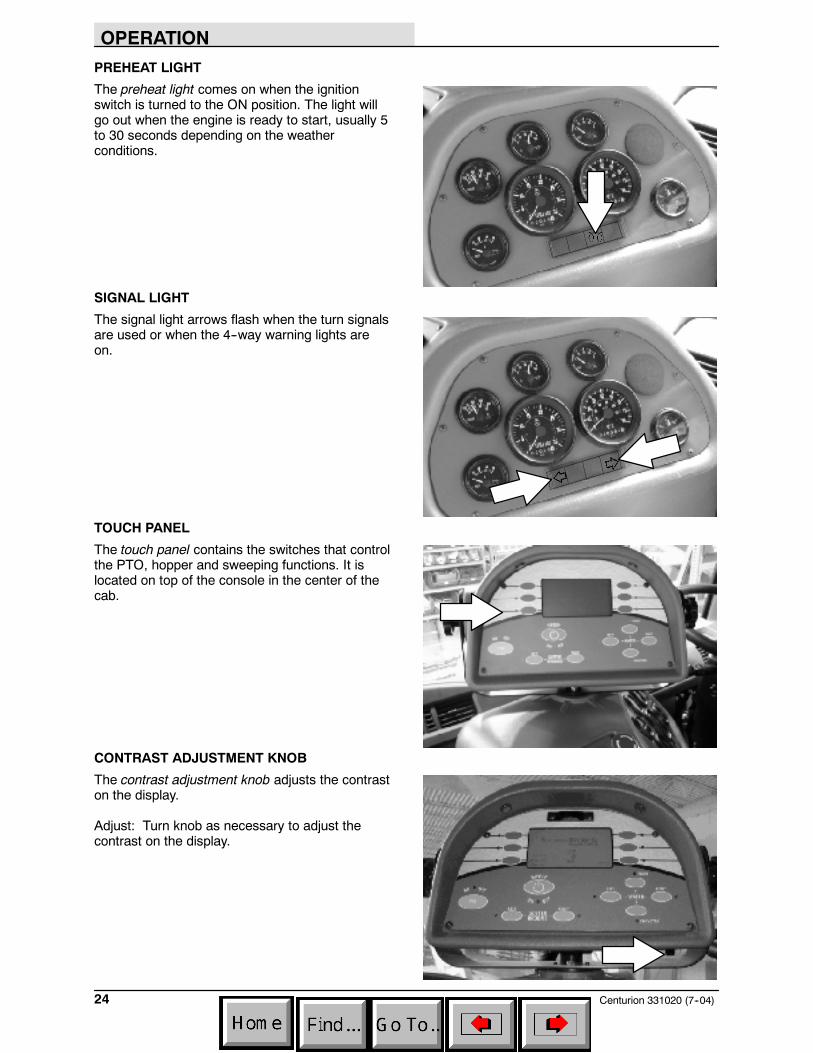
PREHEAT LIGHT
The preheat light comes on when the ignitionswitch is turned to the ON position. The light willgo out when the engine is ready to start, usually 5to 30 seconds depending on the weatherconditions.
SIGNAL LIGHT
The signal light arrows flash when the turn signalsare used or when the 4--way warning lights areon.
TOUCH PANEL
The touch panel contains the switches that controlthe PTO, hopper and sweeping functions. It islocated on top of the console in the center of thecab.
CONTRAST ADJUSTMENT KNOB
The contrast adjustment knob adjusts the contraston the display.
Adjust: Turn knob as necessary to adjust thecontrast on the display.
OPERATION
25Centurion 331020 (11--03)
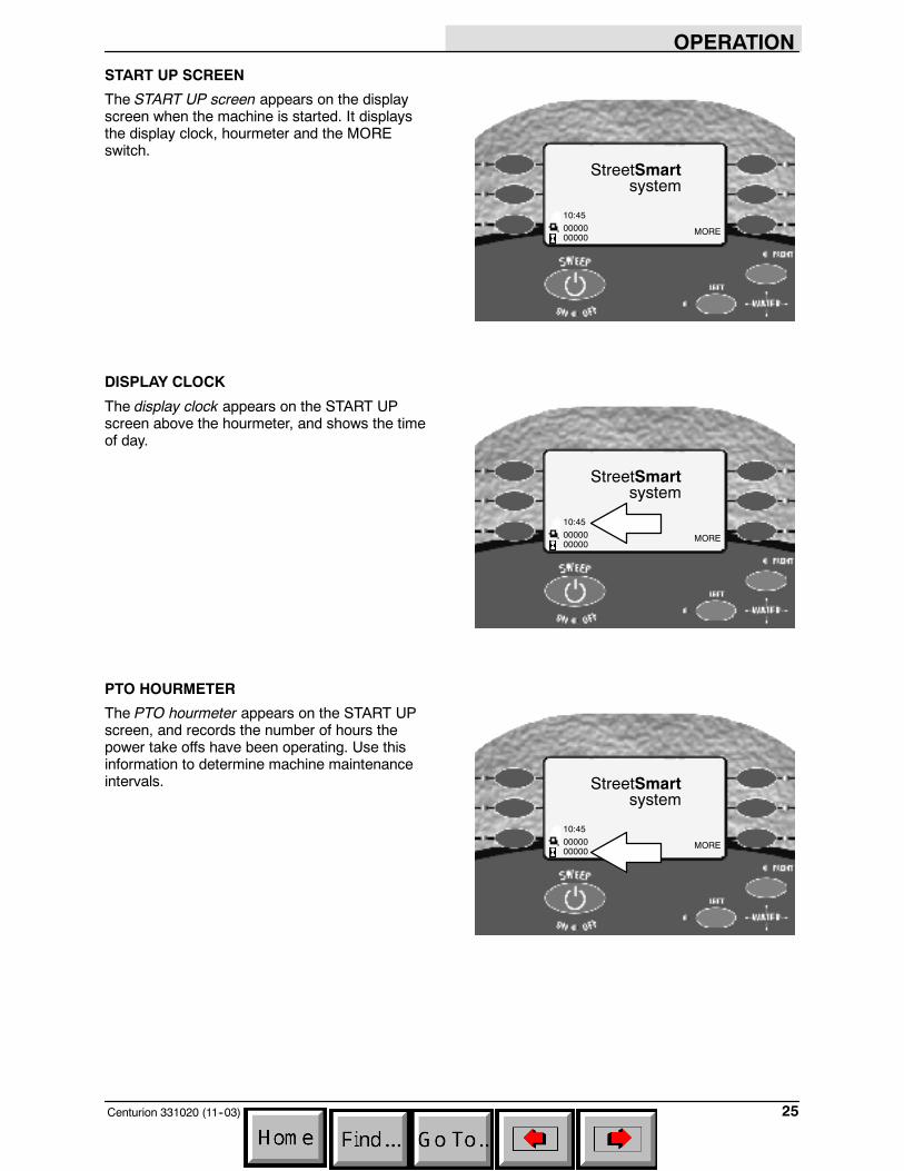
START UP SCREEN
The START UP screen appears on the displayscreen when the machine is started. It displaysthe display clock, hourmeter and the MOREswitch.
DISPLAY CLOCK
The display clock appears on the START UPscreen above the hourmeter, and shows the timeof day.
PTO HOURMETER
The PTO hourmeter appears on the START UPscreen, and records the number of hours thepower take offs have been operating. Use thisinformation to determine machine maintenanceintervals.
MORE
StreetSmartsystem
0000000000
10:45
MORE
StreetSmartsystem
0000000000
10:45
MORE
StreetSmartsystem
0000000000
10:45

OPERATION
Centurion 331020 (11--03)26
BRUSH HOURMETER
The brush hourmeter appears on the START UPscreen, and records the number of hours the mainbroom has been operating. Use this information todetermine machine maintenance intervals.
The display clock and brush hourmeter canbe set with the time adjust/brush hour resetscreen. Continue pressing the more switch tocycle through the six operating screens until thetime adjust/brush hour reset screen appears.Adjust the time using the buttons on either side ofthe display panel.
MORE SWITCH
The MORE switch appears on the START UPscreen and the three operating screens. Press theswitch once to cycle to the next screen. Theswitch will continue cycling through the fivescreens each time it is pressed.
MORE
StreetSmartsystem
0000000000
10:45
ADJUST TIME
RESET BRUSH HR
MORE
MORE
StreetSmartsystem
0000000000
10:45
OPERATION
27Centurion 331020 (7--04)
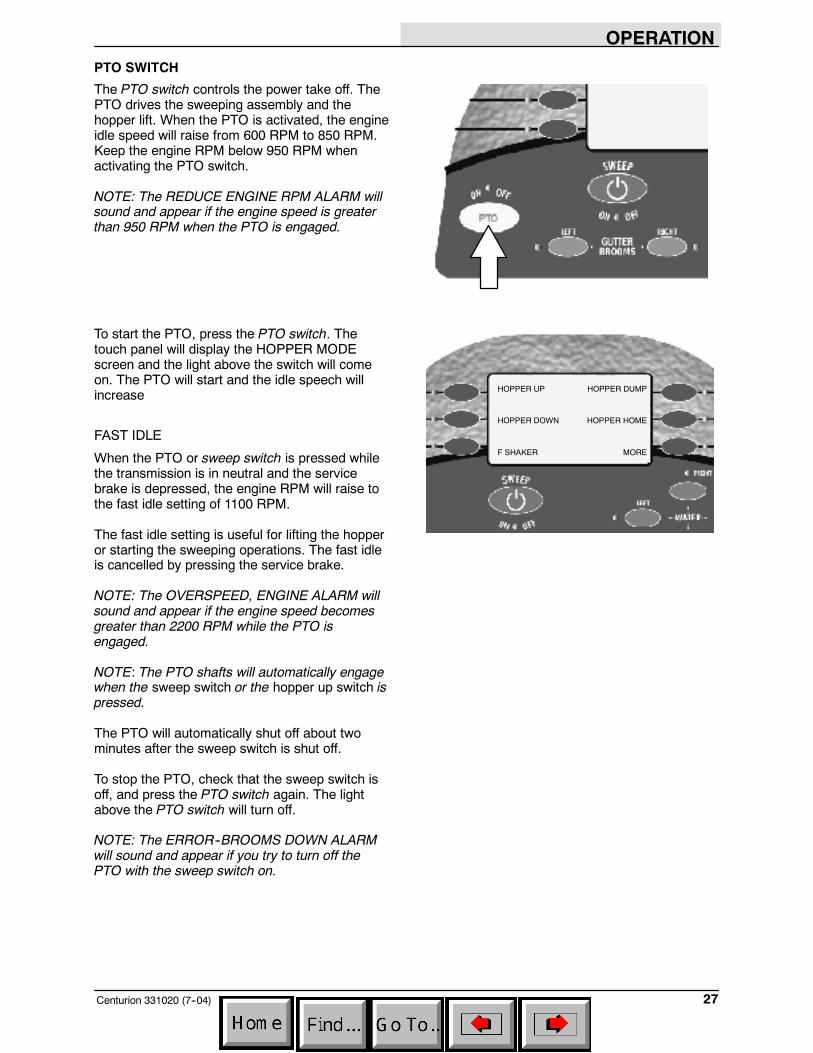
PTO SWITCH
The PTO switch controls the power take off. ThePTO drives the sweeping assembly and thehopper lift. When the PTO is activated, the engineidle speed will raise from 600 RPM to 850 RPM.Keep the engine RPM below 950 RPM whenactivating the PTO switch.
NOTE: The REDUCE ENGINE RPM ALARM willsound and appear if the engine speed is greaterthan 950 RPM when the PTO is engaged.
To start the PTO, press the PTO switch. Thetouch panel will display the HOPPER MODEscreen and the light above the switch will comeon. The PTO will start and the idle speech willincrease
FAST IDLE
When the PTO or sweep switch is pressed whilethe transmission is in neutral and the servicebrake is depressed, the engine RPM will raise tothe fast idle setting of 1100 RPM.
The fast idle setting is useful for lifting the hopperor starting the sweeping operations. The fast idleis cancelled by pressing the service brake.
NOTE: The OVERSPEED, ENGINE ALARM willsound and appear if the engine speed becomesgreater than 2200 RPM while the PTO isengaged.
NOTE: The PTO shafts will automatically engagewhen the sweep switch or the hopper up switch ispressed.
The PTO will automatically shut off about twominutes after the sweep switch is shut off.
To stop the PTO, check that the sweep switch isoff, and press the PTO switch again. The lightabove the PTO switch will turn off.
NOTE: The ERROR--BROOMS DOWN ALARMwill sound and appear if you try to turn off thePTO with the sweep switch on.
HOPPER UP
HOPPER DOWN
F SHAKER
HOPPER DUMP
HOPPER HOME
MORE
OPERATION
Centurion 331020 (7--04)28
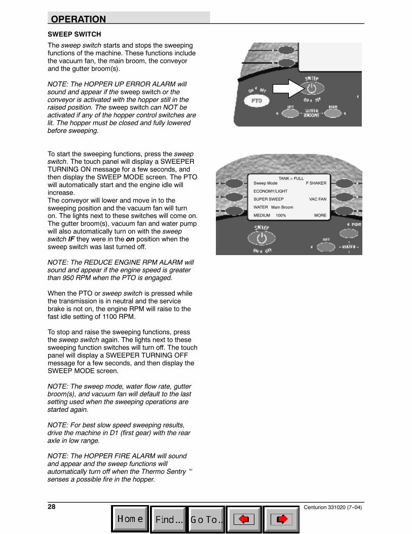
SWEEP SWITCH
The sweep switch starts and stops the sweepingfunctions of the machine. These functions includethe vacuum fan, the main broom, the conveyorand the gutter broom(s).
NOTE: The HOPPER UP ERROR ALARM willsound and appear if the sweep switch or theconveyor is activated with the hopper still in theraised position. The sweep switch can NOT beactivated if any of the hopper control switches arelit. The hopper must be closed and fully loweredbefore sweeping.
To start the sweeping functions, press the sweepswitch. The touch panel will display a SWEEPERTURNING ON message for a few seconds, andthen display the SWEEP MODE screen. The PTOwill automatically start and the engine idle willincrease.The conveyor will lower and move in to thesweeping position and the vacuum fan will turnon. The lights next to these switches will come on.The gutter broom(s), vacuum fan and water pumpwill also automatically turn on with the sweepswitch IF they were in the on position when thesweep switch was last turned off.
NOTE: The REDUCE ENGINE RPM ALARM willsound and appear if the engine speed is greaterthan 950 RPM when the PTO is engaged.
When the PTO or sweep switch is pressed whilethe transmission is in neutral and the servicebrake is not on, the engine RPM will raise to thefast idle setting of 1100 RPM.
To stop and raise the sweeping functions, pressthe sweep switch again. The lights next to thesesweeping function switches will turn off. The touchpanel will display a SWEEPER TURNING OFFmessage for a few seconds, and then display theSWEEP MODE screen.
NOTE: The sweep mode, water flow rate, gutterbroom(s), and vacuum fan will default to the lastsetting used when the sweeping operations arestarted again.
NOTE: For best slow speed sweeping results,drive the machine in D1 (first gear) with the rearaxle in low range.
NOTE: The HOPPER FIRE ALARM will soundand appear and the sweep functions willautomatically turn off when the Thermo Sentrytsenses a possible fire in the hopper.
Sweep Mode
ECONOMY/LIGHT
SUPER SWEEP
WATER Main Broom
MEDIUM 100%
F SHAKER
VAC FAN
MORE
TANK = FULL
OPERATION
29Centurion 331020 (11--03)
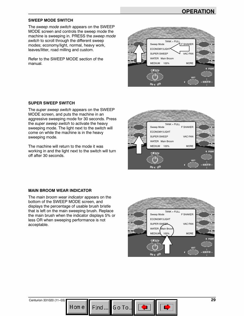
SWEEP MODE SWITCH
The sweep mode switch appears on the SWEEPMODE screen and controls the sweep mode themachine is sweeping in. PRESS the sweep modeswitch to scroll through the different sweepmodes; economy/light, normal, heavy work,leaves/litter, road milling and custom.
Refer to the SWEEP MODE section of themanual.
SUPER SWEEP SWITCH
The super sweep switch appears on the SWEEPMODE screen, and puts the machine in anaggressive sweeping mode for 30 seconds. Pressthe super sweep switch to activate the heavysweeping mode. The light next to the switch willcome on while the machine is in the heavysweeping mode.
The machine will return to the mode it wasworking in and the light next to the switch will turnoff after 30 seconds.
MAIN BROOM WEAR INDICATOR
The main broom wear indicator appears on thebottom of the SWEEP MODE screen, anddisplays the percentage of usable brush bristlethat is left on the main sweeping brush. Replacethe main brush when the indicator displays 5% orless OR when sweeping performance is notacceptable.
Sweep Mode
ECONOMY/LIGHT
SUPER SWEEP
WATER Main Broom
MEDIUM 100%
F SHAKER
VAC FAN
MORE
TANK = FULL
Sweep Mode
ECONOMY/LIGHT
SUPER SWEEP
WATER Main Broom
MEDIUM 100%
F SHAKER
VAC FAN
MORE
TANK = FULL
Sweep Mode
ECONOMY/LIGHT
SUPER SWEEP
WATER Main Broom
MEDIUM 100%
F SHAKER
VAC FAN
MORE
TANK = FULL
OPERATION
Centurion 331020 (11--03)30
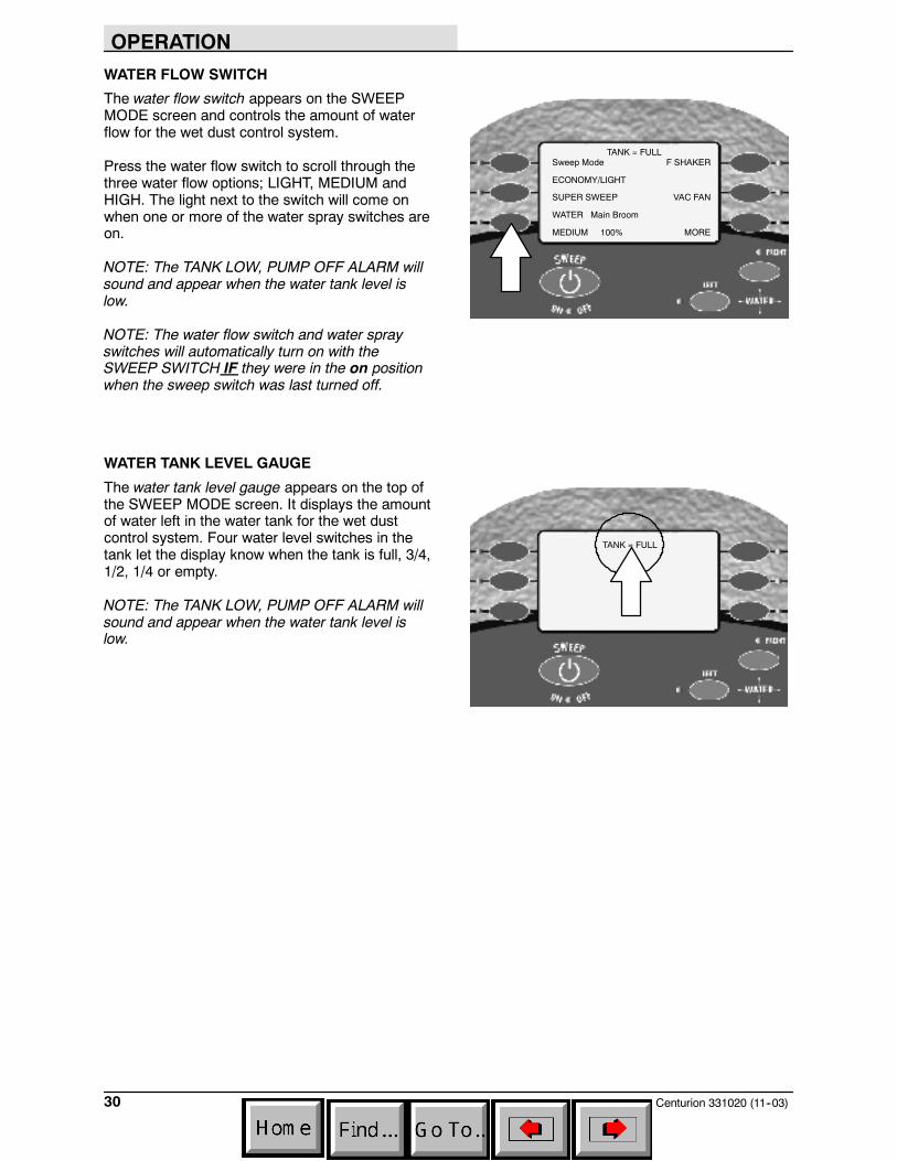
WATER FLOW SWITCH
The water flow switch appears on the SWEEPMODE screen and controls the amount of waterflow for the wet dust control system.
Press the water flow switch to scroll through thethree water flow options; LIGHT, MEDIUM andHIGH. The light next to the switch will come onwhen one or more of the water spray switches areon.
NOTE: The TANK LOW, PUMP OFF ALARM willsound and appear when the water tank level islow.
NOTE: The water flow switch and water sprayswitches will automatically turn on with theSWEEP SWITCH IF they were in the on positionwhen the sweep switch was last turned off.
WATER TANK LEVEL GAUGE
The water tank level gauge appears on the top ofthe SWEEP MODE screen. It displays the amountof water left in the water tank for the wet dustcontrol system. Four water level switches in thetank let the display know when the tank is full, 3/4,1/2, 1/4 or empty.
NOTE: The TANK LOW, PUMP OFF ALARM willsound and appear when the water tank level islow.
Sweep Mode
ECONOMY/LIGHT
SUPER SWEEP
WATER Main Broom
MEDIUM 100%
F SHAKER
VAC FAN
MORE
TANK = FULL
TANK = FULL
OPERATION
31Centurion 331020 (11--03)
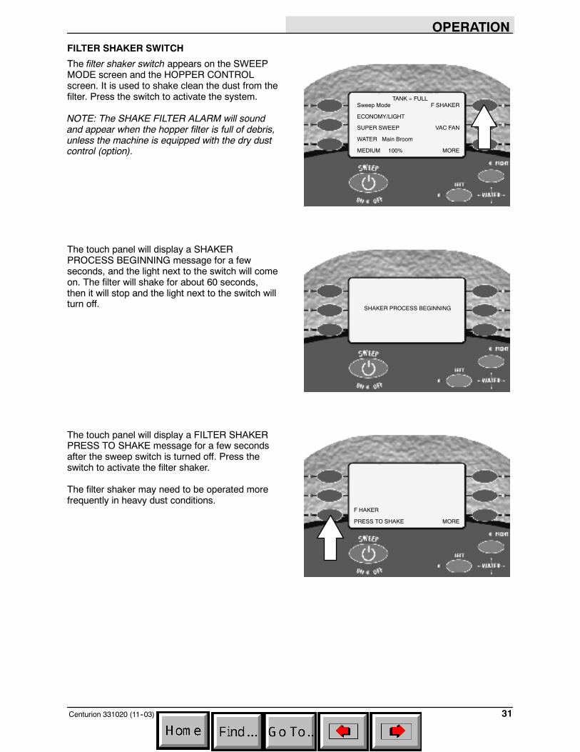
FILTER SHAKER SWITCH
The filter shaker switch appears on the SWEEPMODE screen and the HOPPER CONTROLscreen. It is used to shake clean the dust from thefilter. Press the switch to activate the system.
NOTE: The SHAKE FILTER ALARM will soundand appear when the hopper filter is full of debris,unless the machine is equipped with the dry dustcontrol (option).
The touch panel will display a SHAKERPROCESS BEGINNING message for a fewseconds, and the light next to the switch will comeon. The filter will shake for about 60 seconds,then it will stop and the light next to the switch willturn off.
The touch panel will display a FILTER SHAKERPRESS TO SHAKE message for a few secondsafter the sweep switch is turned off. Press theswitch to activate the filter shaker.
The filter shaker may need to be operated morefrequently in heavy dust conditions.
Sweep Mode
ECONOMY/LIGHT
SUPER SWEEP
WATER Main Broom
MEDIUM 100%
F SHAKER
VAC FAN
MORE
TANK = FULL
SHAKER PROCESS BEGINNING
F HAKER
PRESS TO SHAKE MORE
OPERATION
Centurion 331020 (11--03)32
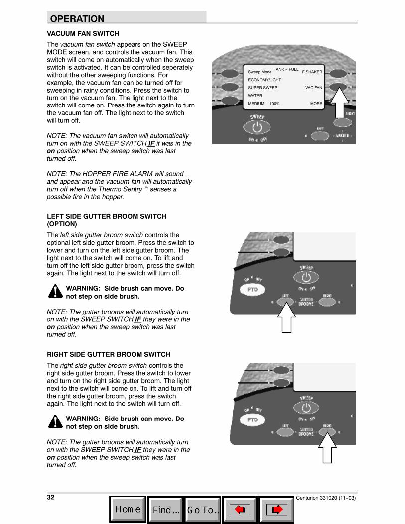
VACUUM FAN SWITCH
The vacuum fan switch appears on the SWEEPMODE screen, and controls the vacuum fan. Thisswitch will come on automatically when the sweepswitch is activated. It can be controlled seperatelywithout the other sweeping functions. Forexample, the vacuum fan can be turned off forsweeping in rainy conditions. Press the switch toturn on the vacuum fan. The light next to theswitch will come on. Press the switch again to turnthe vacuum fan off. The light next to the switchwill turn off.
NOTE: The vacuum fan switch will automaticallyturn on with the SWEEP SWITCH IF it was in theon position when the sweep switch was lastturned off.
NOTE: The HOPPER FIRE ALARM will soundand appear and the vacuum fan will automaticallyturn off when the Thermo Sentryt senses apossible fire in the hopper.
LEFT SIDE GUTTER BROOM SWITCH(OPTION)
The left side gutter broom switch controls theoptional left side gutter broom. Press the switch tolower and turn on the left side gutter broom. Thelight next to the switch will come on. To lift andturn off the left side gutter broom, press the switchagain. The light next to the switch will turn off.
WARNING: Side brush can move. Donot step on side brush.
NOTE: The gutter brooms will automatically turnon with the SWEEP SWITCH IF they were in theon position when the sweep switch was lastturned off.
RIGHT SIDE GUTTER BROOM SWITCH
The right side gutter broom switch controls theright side gutter broom. Press the switch to lowerand turn on the right side gutter broom. The lightnext to the switch will come on. To lift and turn offthe right side gutter broom, press the switchagain. The light next to the switch will turn off.
WARNING: Side brush can move. Donot step on side brush.
NOTE: The gutter brooms will automatically turnon with the SWEEP SWITCH IF they were in theon position when the sweep switch was lastturned off.
Sweep Mode
ECONOMY/LIGHT
SUPER SWEEP
WATER
MEDIUM 100%
F SHAKER
VAC FAN
MORE
TANK = FULL
OPERATION
33Centurion 331020 (11--03)
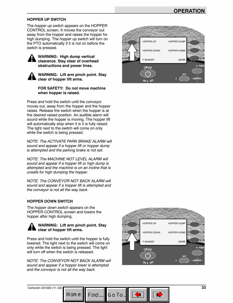
HOPPER UP SWITCH
The hopper up switch appears on the HOPPERCONTROL screen. It moves the conveyor outaway from the hopper and raises the hopper forhigh dumping. The hopper up switch will turn onthe PTO automatically if it is not on before theswitch is pressed.
WARNING: High dump verticalclearance. Stay clear of overheadobstructions and power lines.
WARNING: Lift arm pinch point. Stayclear of hopper lift arms.
FOR SAFETY: Do not move machinewhen hopper is raised.
Press and hold the switch until the conveyormoves out, away from the hopper and the hopperraises. Release the switch when the hopper is atthe desired raised position. An audible alarm willsound while the hopper is moving. The hopper liftwill automatically stop when it is it is fully raised.The light next to the switch will come on onlywhile the switch is being pressed.
NOTE: The ACTIVATE PARK BRAKE ALARM willsound and appear if a hopper lift or hopper dumpis attempted and the parking brake is not set.
NOTE: The MACHINE NOT LEVEL ALARM willsound and appear if a hopper lift or high dump isattempted and the machine is on an incline that isunsafe for high dumping the hopper.
NOTE: The CONVEYOR NOT BACK ALARM willsound and appear if a hopper lift is attempted andthe conveyor is not all the way back.
HOPPER DOWN SWITCH
The hopper down switch appears on theHOPPER CONTROL screen and lowers thehopper after high dumping.
WARNING: Lift arm pinch point. Stayclear of hopper lift arms.
Press and hold the switch until the hopper is fullylowered. The light next to the switch will come ononly while the switch is being pressed. The lightwill turn off when the switch is released.
NOTE: The CONVEYOR NOT BACK ALARM willsound and appear if a hopper lower is attemptedand the conveyor is not all the way back.
HOPPER UP
HOPPER DOWN
F SHAKER
HOPPER DUMP
HOPPER HOME
MORE
HOPPER UP
HOPPER DOWN
F SHAKER
HOPPER DUMP
HOPPER HOME
MORE
OPERATION
Centurion 331020 (11--03)34
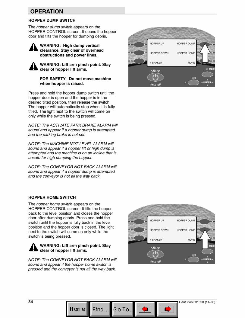
HOPPER DUMP SWITCH
The hopper dump switch appears on theHOPPER CONTROL screen. It opens the hopperdoor and tilts the hopper for dumping debris.
WARNING: High dump verticalclearance. Stay clear of overheadobstructions and power lines.
WARNING: Lift arm pinch point. Stayclear of hopper lift arms.
FOR SAFETY: Do not move machinewhen hopper is raised.
Press and hold the hopper dump switch until thehopper door is open and the hopper is in thedesired tilted position, then release the switch.The hopper will automatically stop when it is fullytitled. The light next to the switch will come ononly while the switch is being pressed.
NOTE: The ACTIVATE PARK BRAKE ALARM willsound and appear if a hopper dump is attemptedand the parking brake is not set.
NOTE: The MACHINE NOT LEVEL ALARM willsound and appear if a hopper lift or high dump isattempted and the machine is on an incline that isunsafe for high dumping the hopper.
NOTE: The CONVEYOR NOT BACK ALARM willsound and appear if a hopper dump is attemptedand the conveyor is not all the way back.
HOPPER HOME SWITCH
The hopper home switch appears on theHOPPER CONTROL screen. It tilts the hopperback to the level position and closes the hopperdoor after dumping debris. Press and hold theswitch until the hopper is fully back in the levelposition and the hopper door is closed. The lightnext to the switch will come on only while theswitch is being pressed.
WARNING: Lift arm pinch point. Stayclear of hopper lift arms.
NOTE: The CONVEYOR NOT BACK ALARM willsound and appear if the hopper home switch ispressed and the conveyor is not all the way back.
HOPPER UP
HOPPER DOWN
F SHAKER
HOPPER DUMP
HOPPER HOME
MORE
HOPPER UP
HOPPER DOWN
F SHAKER
HOPPER DUMP
HOPPER HOME
MORE
OPERATION
35Centurion 331020 (11--03)
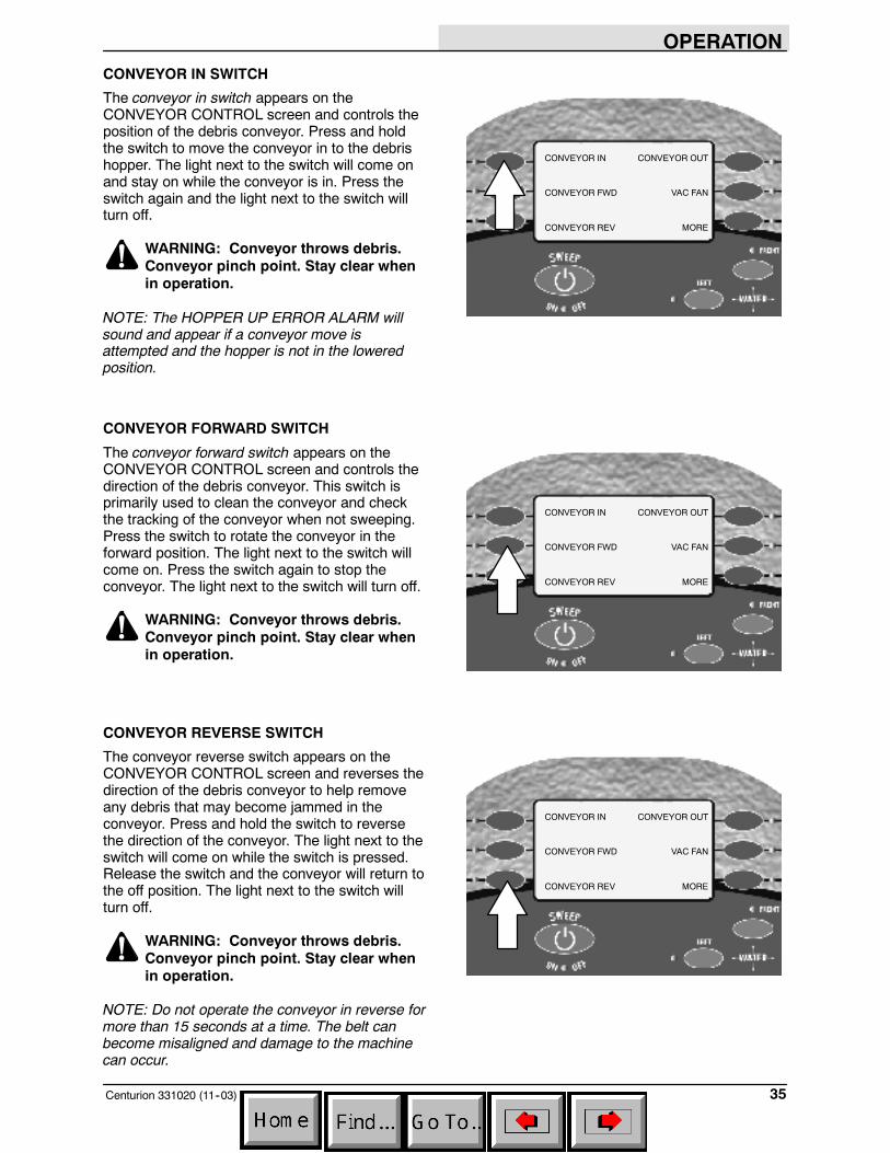
CONVEYOR IN SWITCH
The conveyor in switch appears on theCONVEYOR CONTROL screen and controls theposition of the debris conveyor. Press and holdthe switch to move the conveyor in to the debrishopper. The light next to the switch will come onand stay on while the conveyor is in. Press theswitch again and the light next to the switch willturn off.
WARNING: Conveyor throws debris.Conveyor pinch point. Stay clear whenin operation.
NOTE: The HOPPER UP ERROR ALARM willsound and appear if a conveyor move isattempted and the hopper is not in the loweredposition.
CONVEYOR FORWARD SWITCH
The conveyor forward switch appears on theCONVEYOR CONTROL screen and controls thedirection of the debris conveyor. This switch isprimarily used to clean the conveyor and checkthe tracking of the conveyor when not sweeping.Press the switch to rotate the conveyor in theforward position. The light next to the switch willcome on. Press the switch again to stop theconveyor. The light next to the switch will turn off.
WARNING: Conveyor throws debris.Conveyor pinch point. Stay clear whenin operation.
CONVEYOR REVERSE SWITCH
The conveyor reverse switch appears on theCONVEYOR CONTROL screen and reverses thedirection of the debris conveyor to help removeany debris that may become jammed in theconveyor. Press and hold the switch to reversethe direction of the conveyor. The light next to theswitch will come on while the switch is pressed.Release the switch and the conveyor will return tothe off position. The light next to the switch willturn off.
WARNING: Conveyor throws debris.Conveyor pinch point. Stay clear whenin operation.
NOTE: Do not operate the conveyor in reverse formore than 15 seconds at a time. The belt canbecome misaligned and damage to the machinecan occur.
CONVEYOR IN
CONVEYOR FWD
CONVEYOR REV
CONVEYOR OUT
VAC FAN
MORE
CONVEYOR IN
CONVEYOR FWD
CONVEYOR REV
CONVEYOR OUT
VAC FAN
MORE
CONVEYOR IN
CONVEYOR FWD
CONVEYOR REV
CONVEYOR OUT
VAC FAN
MORE
OPERATION
Centurion 331020 (11--03)36
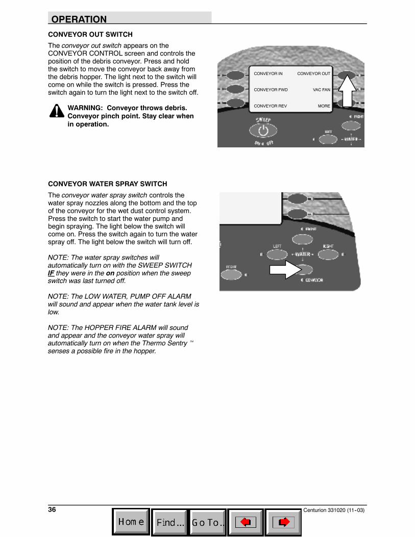
CONVEYOR OUT SWITCH
The conveyor out switch appears on theCONVEYOR CONTROL screen and controls theposition of the debris conveyor. Press and holdthe switch to move the conveyor back away fromthe debris hopper. The light next to the switch willcome on while the switch is pressed. Press theswitch again to turn the light next to the switch off.
WARNING: Conveyor throws debris.Conveyor pinch point. Stay clear whenin operation.
CONVEYOR WATER SPRAY SWITCH
The conveyor water spray switch controls thewater spray nozzles along the bottom and the topof the conveyor for the wet dust control system.Press the switch to start the water pump andbegin spraying. The light below the switch willcome on. Press the switch again to turn the waterspray off. The light below the switch will turn off.
NOTE: The water spray switches willautomatically turn on with the SWEEP SWITCHIF they were in the on position when the sweepswitch was last turned off.
NOTE: The LOW WATER, PUMP OFF ALARMwill sound and appear when the water tank level islow.
NOTE: The HOPPER FIRE ALARM will soundand appear and the conveyor water spray willautomatically turn on when the Thermo Sentrytsenses a possible fire in the hopper.
CONVEYOR IN
CONVEYOR FWD
CONVEYOR REV
CONVEYOR OUT
VAC FAN
MORE
OPERATION
37Centurion 331020 (11--03)
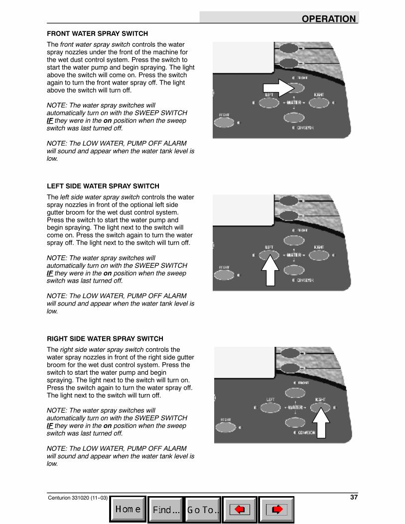
FRONT WATER SPRAY SWITCH
The front water spray switch controls the waterspray nozzles under the front of the machine forthe wet dust control system. Press the switch tostart the water pump and begin spraying. The lightabove the switch will come on. Press the switchagain to turn the front water spray off. The lightabove the switch will turn off.
NOTE: The water spray switches willautomatically turn on with the SWEEP SWITCHIF they were in the on position when the sweepswitch was last turned off.
NOTE: The LOW WATER, PUMP OFF ALARMwill sound and appear when the water tank level islow.
LEFT SIDE WATER SPRAY SWITCH
The left side water spray switch controls the waterspray nozzles in front of the optional left sidegutter broom for the wet dust control system.Press the switch to start the water pump andbegin spraying. The light next to the switch willcome on. Press the switch again to turn the waterspray off. The light next to the switch will turn off.
NOTE: The water spray switches willautomatically turn on with the SWEEP SWITCHIF they were in the on position when the sweepswitch was last turned off.
NOTE: The LOW WATER, PUMP OFF ALARMwill sound and appear when the water tank level islow.
RIGHT SIDE WATER SPRAY SWITCH
The right side water spray switch controls thewater spray nozzles in front of the right side gutterbroom for the wet dust control system. Press theswitch to start the water pump and beginspraying. The light next to the switch will turn on.Press the switch again to turn the water spray off.The light next to the switch will turn off.
NOTE: The water spray switches willautomatically turn on with the SWEEP SWITCHIF they were in the on position when the sweepswitch was last turned off.
NOTE: The LOW WATER, PUMP OFF ALARMwill sound and appear when the water tank level islow.
OPERATION
Centurion 331020 (11--03)38
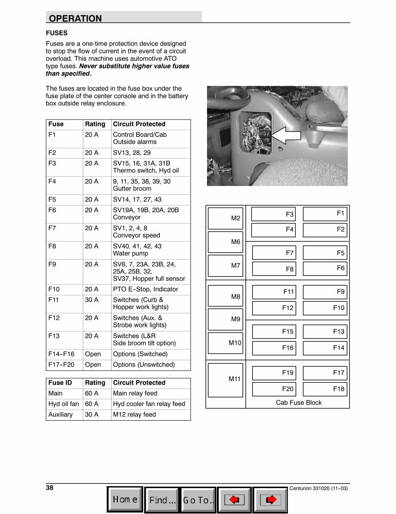
FUSES
Fuses are a one-time protection device designedto stop the flow of current in the event of a circuitoverload. This machine uses automotive ATOtype fuses. Never substitute higher value fusesthan specified.
The fuses are located in the fuse box under thefuse plate of the center console and in the batterybox outside relay enclosure.
Fuse Rating Circuit Protected
F1 20 A Control Board/CabOutside alarms
F2 20 A SV13, 28, 29
F3 20 A SV15, 16, 31A, 31BThermo switch, Hyd oil
F4 20 A 9, 11, 35, 38, 39, 30Gutter broom
F5 20 A SV14, 17, 27, 43
F6 20 A SV19A, 19B, 20A, 20BConveyor
F7 20 A SV1, 2, 4, 8Conveyor speed
F8 20 A SV40, 41, 42, 43Water pump
F9 20 A SV6, 7, 23A, 23B, 24,25A, 25B, 32,SV37, Hopper full sensor
F10 20 A PTO E--Stop, Indicator
F11 30 A Switches (Curb &Hopper work lights)
F12 20 A Switches (Aux. &Strobe work lights)
F13 20 A Switches (L&RSide broom tilt option)
F14--F16 Open Options (Switched)
F17--F20 Open Options (Unswitched)
Fuse ID Rating Circuit Protected
Main 60 A Main relay feed
Hyd oil fan 60 A Hyd cooler fan relay feed
Auxiliary 30 A M12 relay feed
F1
F2
F3
F4
F5
F6
F7
F8
F9
F10
F11
F12
F13
F14
F15
F16
F17
F18
F19
F20
M2
M6
M7
M8
M9
M10
M11
Cab Fuse Block
OPERATION
39Centurion 331020 (9--05)
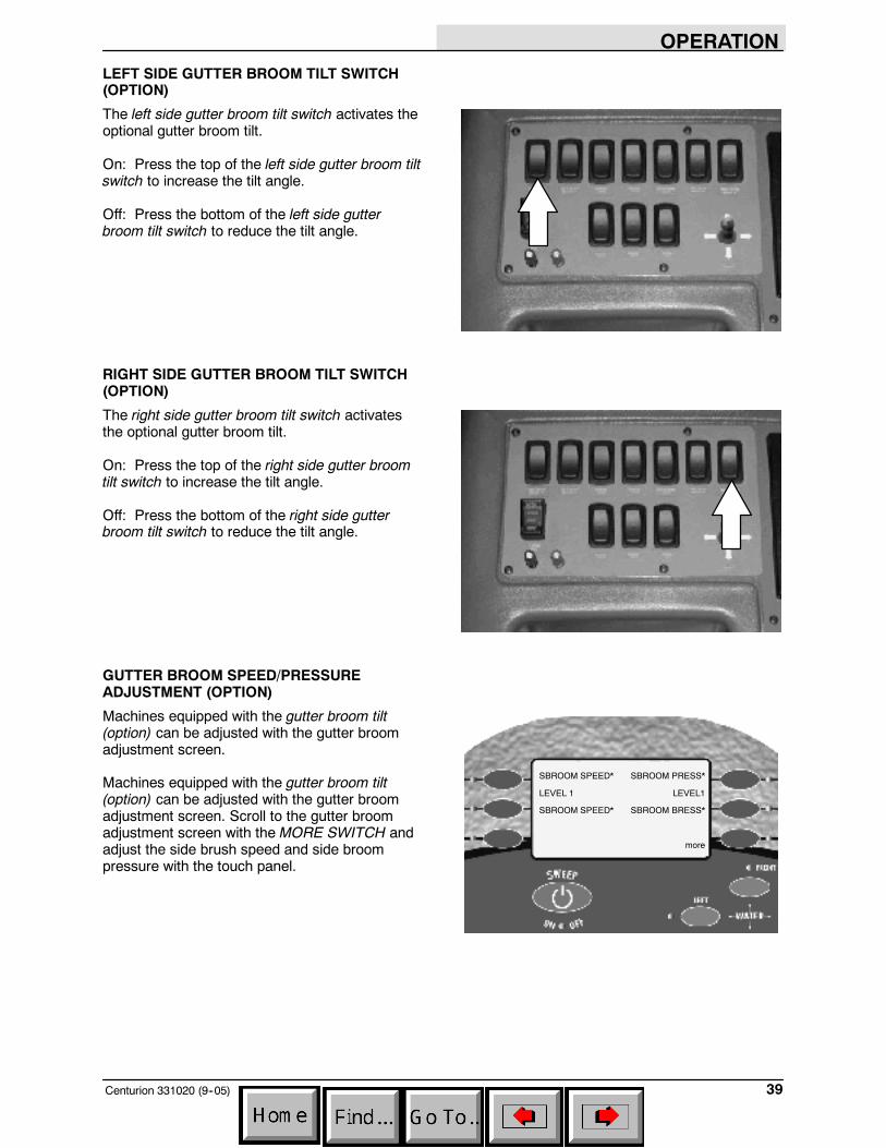
LEFT SIDE GUTTER BROOM TILT SWITCH(OPTION)
The left side gutter broom tilt switch activates theoptional gutter broom tilt.
On: Press the top of the left side gutter broom tiltswitch to increase the tilt angle.
Off: Press the bottom of the left side gutterbroom tilt switch to reduce the tilt angle.
RIGHT SIDE GUTTER BROOM TILT SWITCH(OPTION)
The right side gutter broom tilt switch activatesthe optional gutter broom tilt.
On: Press the top of the right side gutter broomtilt switch to increase the tilt angle.
Off: Press the bottom of the right side gutterbroom tilt switch to reduce the tilt angle.
GUTTER BROOM SPEED/PRESSUREADJUSTMENT (OPTION)
Machines equipped with the gutter broom tilt(option) can be adjusted with the gutter broomadjustment screen.
Machines equipped with the gutter broom tilt(option) can be adjusted with the gutter broomadjustment screen. Scroll to the gutter broomadjustment screen with the MORE SWITCH andadjust the side brush speed and side broompressure with the touch panel.
SBROOM SPEED*
LEVEL 1
SBROOM SPEED*
SBROOM PRESS*
LEVEL1
SBROOM BRESS*
more
OPERATION
Centurion 331020 (9--05)40
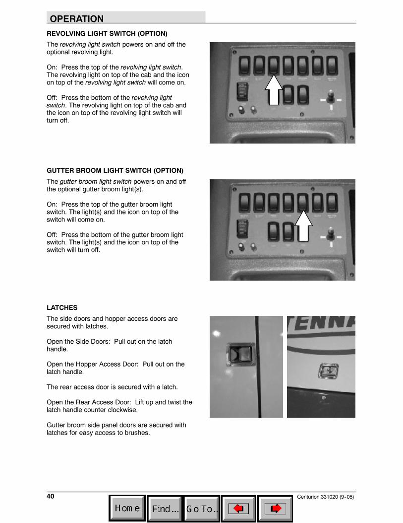
REVOLVING LIGHT SWITCH (OPTION)
The revolving light switch powers on and off theoptional revolving light.
On: Press the top of the revolving light switch.The revolving light on top of the cab and the iconon top of the revolving light switch will come on.
Off: Press the bottom of the revolving lightswitch. The revolving light on top of the cab andthe icon on top of the revolving light switch willturn off.
GUTTER BROOM LIGHT SWITCH (OPTION)
The gutter broom light switch powers on and offthe optional gutter broom light(s).
On: Press the top of the gutter broom lightswitch. The light(s) and the icon on top of theswitch will come on.
Off: Press the bottom of the gutter broom lightswitch. The light(s) and the icon on top of theswitch will turn off.
LATCHES
The side doors and hopper access doors aresecured with latches.
Open the Side Doors: Pull out on the latchhandle.
Open the Hopper Access Door: Pull out on thelatch handle.
The rear access door is secured with a latch.
Open the Rear Access Door: Lift up and twist thelatch handle counter clockwise.
Gutter broom side panel doors are secured withlatches for easy access to brushes.

OPERATION
41Centurion 331020 (11--03)
HOPPER TILT SUPPORT BAR
The hopper tilt support bar holds the hopper in thetilt position to allow work under the hopper. DONOT rely on the machine hydraulic system tokeep the hopper raised. See ENGAGINGHOPPER TILT SUPPORT BAR section of thismanual.
WARNING: Raised hopper may fall.Engage hopper support bar.
The hopper tilt support bar is stored in the rear ofthe machine, next to the hopper lift cylinders.
HOPPER LIFT SUPPORT BARS
The hopper lift support bars hold the hopper lift inthe raised position to allow work under the hopperlift. DO NOT rely on the machine hydraulic systemto keep the hopper lift in the raised position. SeeENGAGING HOPPER LIFT SUPPORT BARSsection of this manual.
WARNING: Raised hopper may fall.Engage hopper support bar.
OPERATION
Centurion 331020 (11--03)42
ALARMS
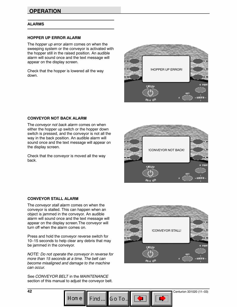
HOPPER UP ERROR ALARM
The hopper up error alarm comes on when thesweeping system or the conveyor is activated withthe hopper still in the raised position. An audiblealarm will sound once and the text message willappear on the display screen.
Check that the hopper is lowered all the waydown.
CONVEYOR NOT BACK ALARM
The conveyor not back alarm comes on wheneither the hopper up switch or the hopper downswitch is pressed, and the conveyor is not all theway in the back position. An audible alarm willsound once and the text message will appear onthe display screen.
Check that the conveyor is moved all the wayback.
CONVEYOR STALL ALARM
The conveyor stall alarm comes on when theconveyor is stalled. This can happen when anobject is jammed in the conveyor. An audiblealarm will sound once and the text message willappear on the display screen.The conveyor willturn off when the alarm comes on.
Press and hold the conveyor reverse switch for10--15 seconds to help clear any debris that maybe jammed in the conveyor.
NOTE: Do not operate the conveyor in reverse formore than 15 seconds at a time. The belt canbecome misaligned and damage to the machinecan occur.
See CONVEYOR BELT in the MAINTENANCEsection of this manual to adjust the conveyor belt.
!HOPPER UP ERROR!
!CONVEYOR NOT BACK!
!CONVEYOR STALL!
OPERATION
43Centurion 331020 (11--03)
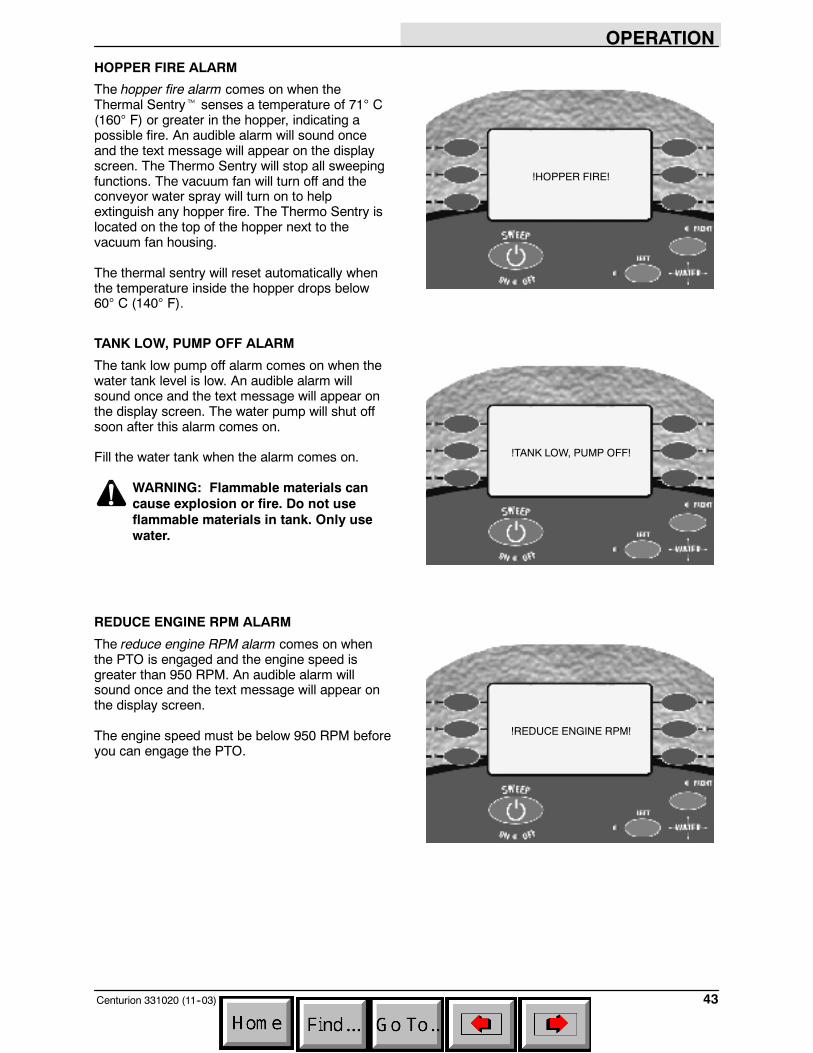
HOPPER FIRE ALARM
The hopper fire alarm comes on when theThermal Sentryt senses a temperature of 71° C(160° F) or greater in the hopper, indicating apossible fire. An audible alarm will sound onceand the text message will appear on the displayscreen. The Thermo Sentry will stop all sweepingfunctions. The vacuum fan will turn off and theconveyor water spray will turn on to helpextinguish any hopper fire. The Thermo Sentry islocated on the top of the hopper next to thevacuum fan housing.
The thermal sentry will reset automatically whenthe temperature inside the hopper drops below60° C (140° F).
TANK LOW, PUMP OFF ALARM
The tank low pump off alarm comes on when thewater tank level is low. An audible alarm willsound once and the text message will appear onthe display screen. The water pump will shut offsoon after this alarm comes on.
Fill the water tank when the alarm comes on.
WARNING: Flammable materials cancause explosion or fire. Do not useflammable materials in tank. Only usewater.
REDUCE ENGINE RPM ALARM
The reduce engine RPM alarm comes on whenthe PTO is engaged and the engine speed isgreater than 950 RPM. An audible alarm willsound once and the text message will appear onthe display screen.
The engine speed must be below 950 RPM beforeyou can engage the PTO.
!HOPPER FIRE!
!TANK LOW, PUMP OFF!
!REDUCE ENGINE RPM!

OPERATION
Centurion 331020 (11--03)44
CHECK HYDRAULIC FILTER ALARM
The check hydraulic filter alarm comes on whenthe hydraulic filter is clogged and the hydraulicfilter bypass switch is activated. An audible alarmwill sound once and the text message will appearon the display screen.
To replace the filter, see HYDRAULIC FILTER inthe MAINTENANCE section of this manual.
ACTIVATE PARK BRAKE ALARM
The activate park brake alarm comes on when thehopper lift or hopper dump is activated without theparking brake set. An audible alarm will soundonce and the text message will appear on thedisplay screen.
Set the machine parking brake before raising ordumping the hopper.
ERROR--BROOMS DOWN ALARM
The error--brooms down alarm comes on whenthe PTO is switch is pressed when the sweepingbrooms are still lowered and sweeping. An audiblealarm will sound once and the text message willappear on the display screen.
Stop the sweeping system before stopping thePTO.
!CHECK HYDR. FILTER!
!ACTIVATE PARK BRAKE!
!ERROR--BROOMS DOWN!

OPERATION
45Centurion 331020 (11--03)
SHAKE FILTER ALARM
The shake filter alarm comes on when the hopperfilter is clogged. An audible alarm will sound onceand the text message will appear on the displayscreen.
Press the filter shaker switch to shake the hopperfilter.
OVERSPEED ENGINE ALARM
The overspeed engine alarm comes on when theengine RPM is greater than 2200 RPM while themachine is sweeping. An audible alarm will soundonce and the text message will appear on thedisplay screen. The sweeping functions will shutoff soon after this alarm comes on.
Keep the engine RPM below 2200 RPM whilesweeping.
RELEASE E--STOP ALARM
The release E--stop alarm comes on when thePTO kill switch is engaged. An audible alarm willsound and the text message will appear on thedisplay screen. All PTO driven functions will shutoff after this alarm comes on.
Press the PTO kill switch again to restart thePTOs.
!SHAKE FILTER!
!OVERSPEED, ENGINE!
!RELEASE E--STOP!
OPERATION
Centurion 331020 (11--03)46
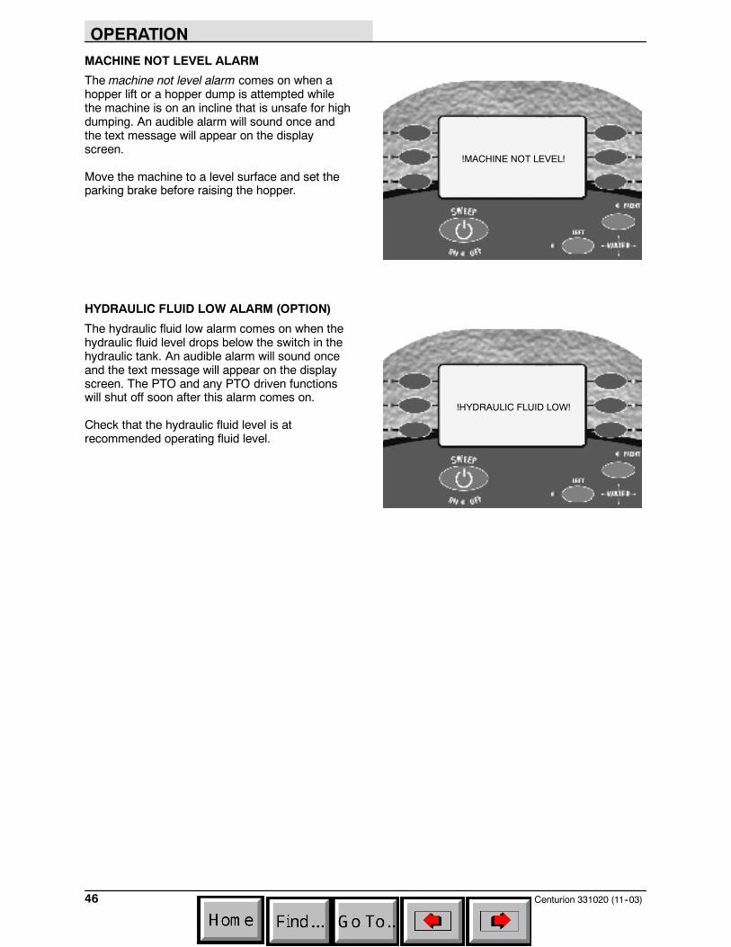
MACHINE NOT LEVEL ALARM
The machine not level alarm comes on when ahopper lift or a hopper dump is attempted whilethe machine is on an incline that is unsafe for highdumping. An audible alarm will sound once andthe text message will appear on the displayscreen.
Move the machine to a level surface and set theparking brake before raising the hopper.
HYDRAULIC FLUID LOW ALARM (OPTION)
The hydraulic fluid low alarm comes on when thehydraulic fluid level drops below the switch in thehydraulic tank. An audible alarm will sound onceand the text message will appear on the displayscreen. The PTO and any PTO driven functionswill shut off soon after this alarm comes on.
Check that the hydraulic fluid level is atrecommended operating fluid level.
!MACHINE NOT LEVEL!
!HYDRAULIC FLUID LOW!
OPERATION
47Centurion 331020 (7--04)
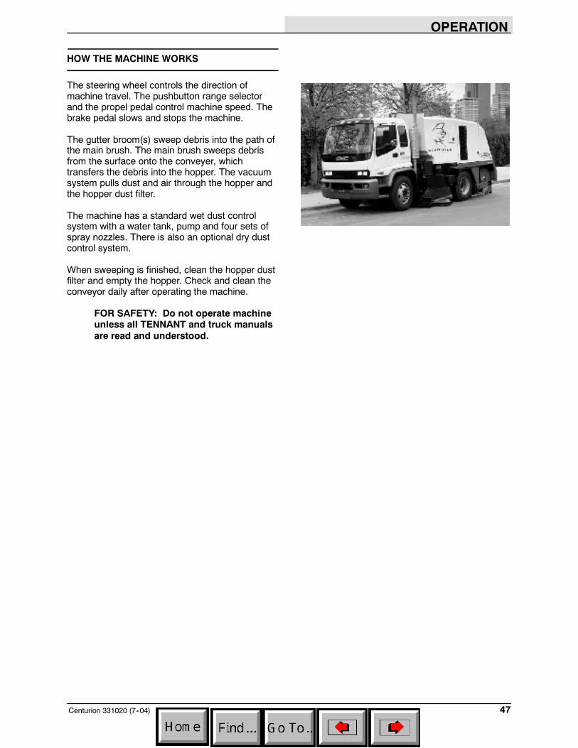
HOW THE MACHINE WORKS
The steering wheel controls the direction ofmachine travel. The pushbutton range selectorand the propel pedal control machine speed. Thebrake pedal slows and stops the machine.
The gutter broom(s) sweep debris into the path ofthe main brush. The main brush sweeps debrisfrom the surface onto the conveyer, whichtransfers the debris into the hopper. The vacuumsystem pulls dust and air through the hopper andthe hopper dust filter.
The machine has a standard wet dust controlsystem with a water tank, pump and four sets ofspray nozzles. There is also an optional dry dustcontrol system.
When sweeping is finished, clean the hopper dustfilter and empty the hopper. Check and clean theconveyor daily after operating the machine.
FOR SAFETY: Do not operate machineunless all TENNANT and truck manualsare read and understood.
OPERATION
Centurion 331020 (7--04)48
PRE AND POST OPERATION CHECKLIST
- Complete the DOT Pre--Trip and Post Trip Inspection.
- Check the fuel level.
- Check the brakes and steering for proper operation.
- Check under the machine for fuel, oil,and coolant leaks.
- Check the engine air filter restriction indicator.
- Check the fuel filter water trap for water.
- Check the radiator core, air conditioner condenser core, and hydraulic cooler fins for debris.
- Check the engine oil level, engine coolant level, hydraulic fluid level, and windshield washer fluid level.
- Check the skirts on the main broom, conveyor, and gutter broom skirts for damage or wear.
- Check the main broom and gutter broom(s) for damage or wear.
- Remove any wire or string tangled on the main or gutter broom(s).
- Check the drag shoes for damage or wear.
- Check the broom pattern adjustments.
- Check the wet dust control water tank level, the water filter, and check and adjust the wet dustcontrol nozzles.
- Flush the conveyor and check the belt for damage, wear, proper tension, and tracking.
- Lubricate the conveyor roller bearings.
- Wash the machine.
- Check service records to determine other maintenance needs.
OPERATION
49Centurion 331020 (9--05)
STARTING THE MACHINE
1. Sit in the operator seat and fasten the seatbelt. Place foot on the brake pedal.
FOR SAFETY: Do not operate machineunless all TENNANT and truck manualsare read and understood.
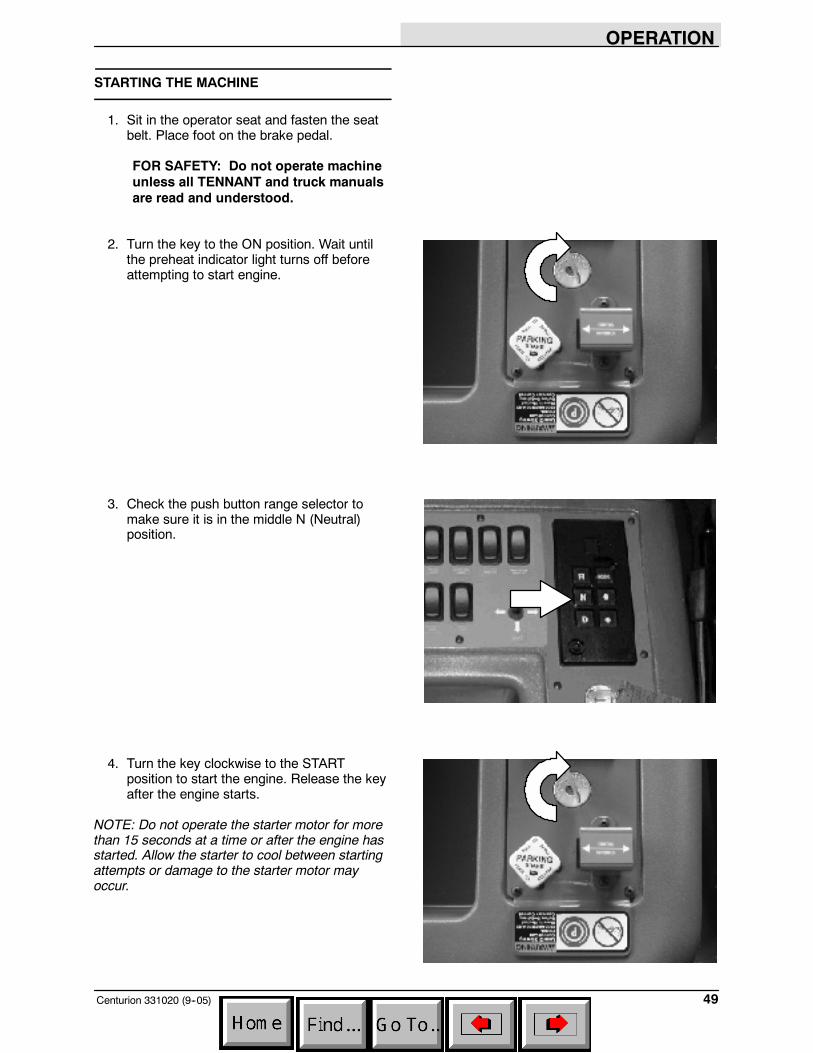
2. Turn the key to the ON position. Wait untilthe preheat indicator light turns off beforeattempting to start engine.
3. Check the push button range selector tomake sure it is in the middle N (Neutral)position.
4. Turn the key clockwise to the STARTposition to start the engine. Release the keyafter the engine starts.
NOTE: Do not operate the starter motor for morethan 15 seconds at a time or after the engine hasstarted. Allow the starter to cool between startingattempts or damage to the starter motor mayoccur.
OPERATION
Centurion 331020 (9--05)50
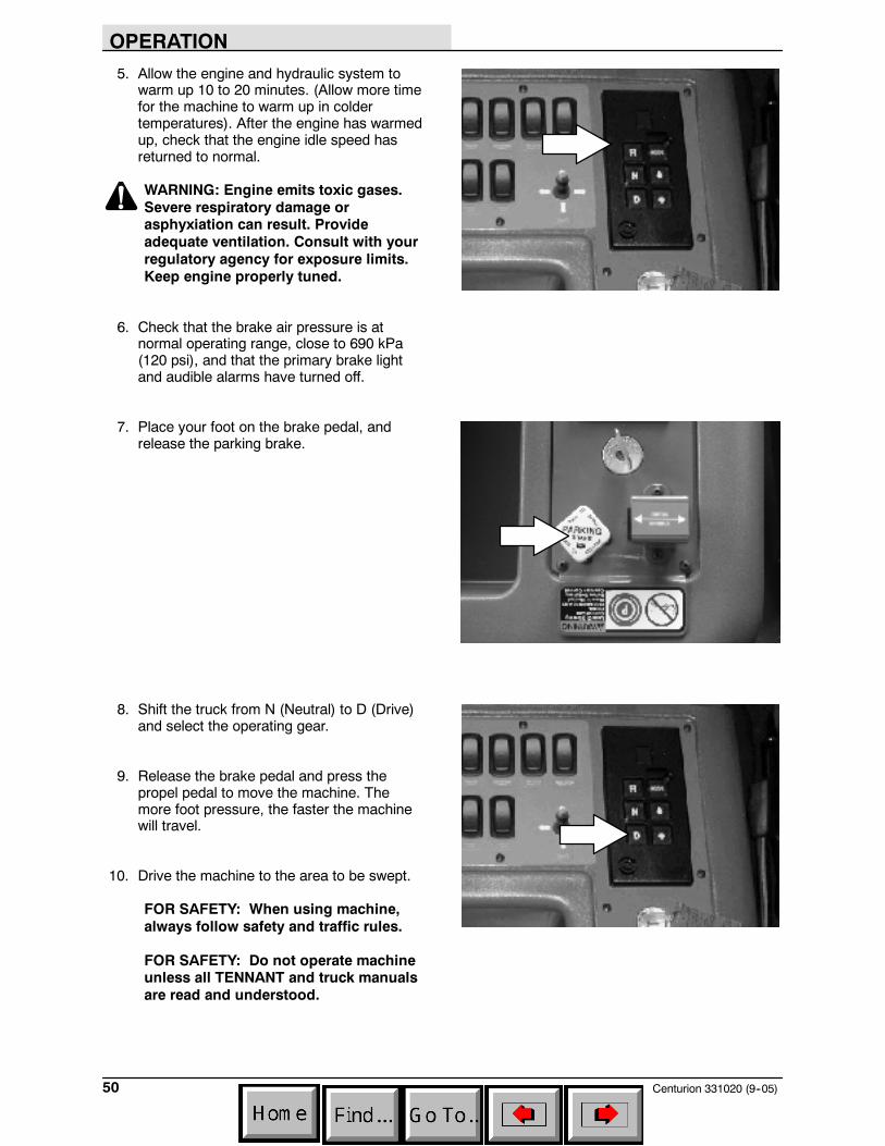
5. Allow the engine and hydraulic system towarm up 10 to 20 minutes. (Allow more timefor the machine to warm up in coldertemperatures). After the engine has warmedup, check that the engine idle speed hasreturned to normal.
WARNING: Engine emits toxic gases.Severe respiratory damage orasphyxiation can result. Provideadequate ventilation. Consult with yourregulatory agency for exposure limits.Keep engine properly tuned.
6. Check that the brake air pressure is atnormal operating range, close to 690 kPa(120 psi), and that the primary brake lightand audible alarms have turned off.
7. Place your foot on the brake pedal, andrelease the parking brake.
8. Shift the truck from N (Neutral) to D (Drive)and select the operating gear.
9. Release the brake pedal and press thepropel pedal to move the machine. Themore foot pressure, the faster the machinewill travel.
10. Drive the machine to the area to be swept.
FOR SAFETY: When using machine,always follow safety and traffic rules.
FOR SAFETY: Do not operate machineunless all TENNANT and truck manualsare read and understood.
OPERATION
51Centurion 331020 (11--03)
SWEEPING AND BRUSH INFORMATION
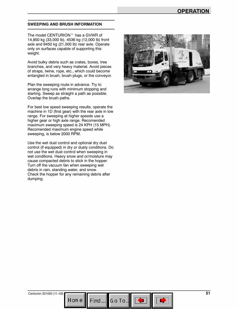
The model CENTURIONt has a GVWR of14,850 kg (33,000 lb), 4536 kg (12,000 lb) frontaxle and 9450 kg (21,000 lb) rear axle. Operateonly on surfaces capable of supporting thisweight.
Avoid bulky debris such as crates, boxes, treebranches, and very heavy material. Avoid piecesof straps, twine, rope, etc., which could becomeentangled in brush, brush plugs, or the conveyor.
Plan the sweeping route in advance. Try toarrange long runs with minimum stopping andstarting. Sweep as straight a path as possible.Overlap the brush paths.
For best low speed sweeping results, operate themachine in 1D (first gear) with the rear axle in lowrange. For sweeping at higher speeds use ahigher gear or high axle range. Recomendedmaximum sweeping speed is 24 KPH (15 MPH).Recomended maximum engine speed whilesweeping, is below 2000 RPM.
Use the wet dust control and optional dry dustcontrol (if equipped) in dry or dusty conditions. Donot use the wet dust control when sweeping inwet conditions. Heavy snow and or/moisture maycause compacted debris to stick in the hopper.Turn off the vacuum fan when sweeping wetdebris in rain, standing water, and snow.Check the hopper for any remaining debris afterdumping.
OPERATION
Centurion 331020 (11--03)52
Polypropylene Main Brush -- A generalpurpose brush used for all sweeping applications.
The following are recommendations for the gutterbroom(s). For best results, use the correct brushtype for your sweeping application.
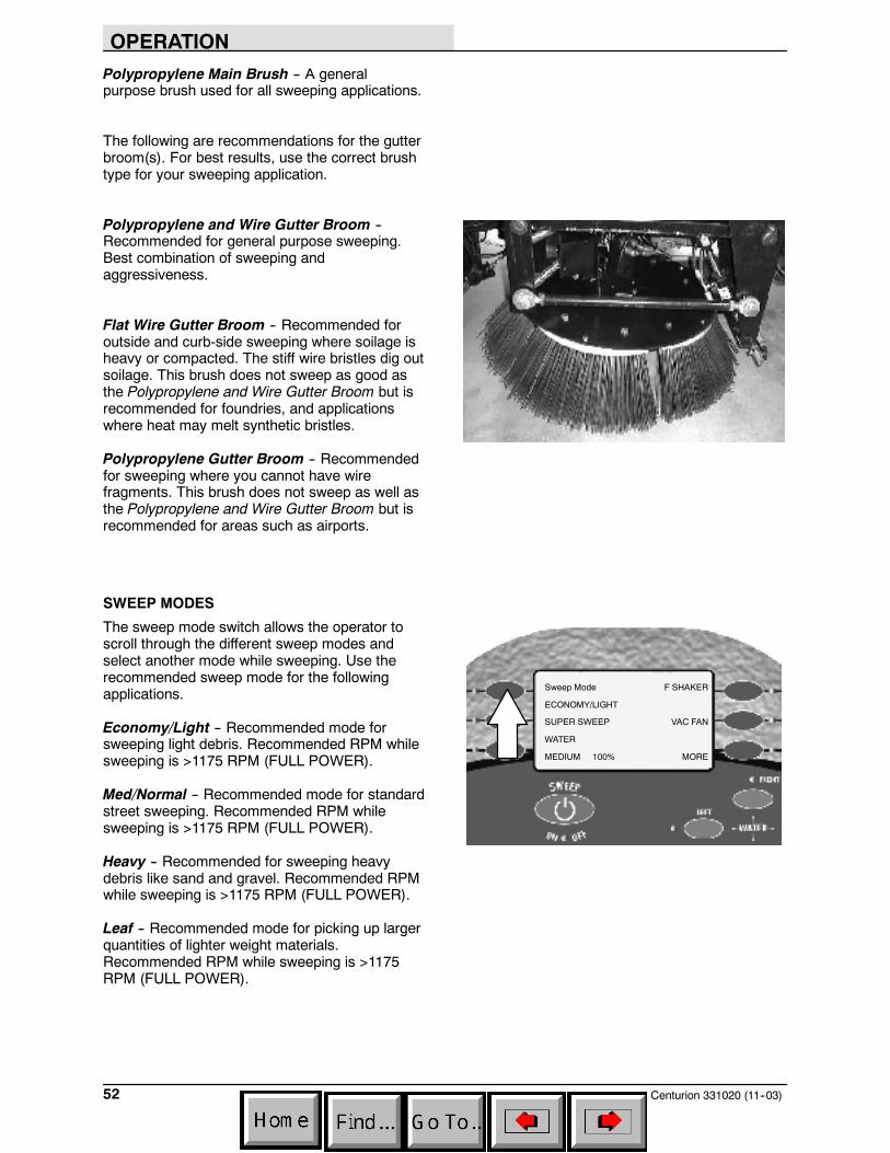
Polypropylene and Wire Gutter Broom --Recommended for general purpose sweeping.Best combination of sweeping andaggressiveness.
Flat Wire Gutter Broom -- Recommended foroutside and curb-side sweeping where soilage isheavy or compacted. The stiff wire bristles dig outsoilage. This brush does not sweep as good asthe Polypropylene and Wire Gutter Broom but isrecommended for foundries, and applicationswhere heat may melt synthetic bristles.
Polypropylene Gutter Broom -- Recommendedfor sweeping where you cannot have wirefragments. This brush does not sweep as well asthe Polypropylene and Wire Gutter Broom but isrecommended for areas such as airports.
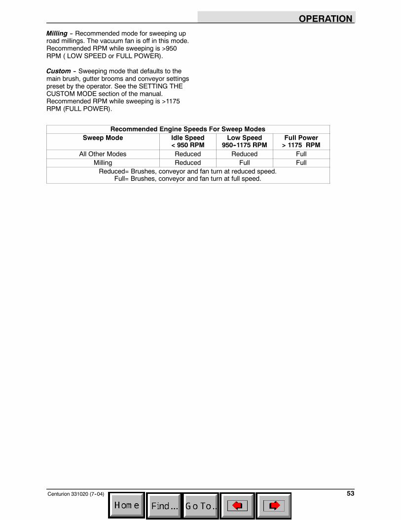
SWEEP MODES
The sweep mode switch allows the operator toscroll through the different sweep modes andselect another mode while sweeping. Use therecommended sweep mode for the followingapplications.
Economy/Light -- Recommended mode forsweeping light debris. Recommended RPM whilesweeping is >1175 RPM (FULL POWER).
Med/Normal -- Recommended mode for standardstreet sweeping. Recommended RPM whilesweeping is >1175 RPM (FULL POWER).
Heavy -- Recommended for sweeping heavydebris like sand and gravel. Recommended RPMwhile sweeping is >1175 RPM (FULL POWER).
Leaf -- Recommended mode for picking up largerquantities of lighter weight materials.Recommended RPM while sweeping is >1175RPM (FULL POWER).
Sweep Mode
ECONOMY/LIGHT
SUPER SWEEP
WATER
MEDIUM 100%
F SHAKER
VAC FAN
MORE
OPERATION
53Centurion 331020 (7--04)
Milling -- Recommended mode for sweeping uproad millings. The vacuum fan is off in this mode.Recommended RPM while sweeping is >950RPM ( LOW SPEED or FULL POWER).
Custom -- Sweeping mode that defaults to themain brush, gutter brooms and conveyor settingspreset by the operator. See the SETTING THECUSTOM MODE section of the manual.Recommended RPM while sweeping is >1175RPM (FULL POWER).
Recommended Engine Speeds For Sweep ModesSweep Mode Idle Speed
< 950 RPMLow Speed
950--1175 RPMFull Power> 1175 RPM
All Other Modes Reduced Reduced FullMilling Reduced Full FullReduced= Brushes, conveyor and fan turn at reduced speed.
Full= Brushes, conveyor and fan turn at full speed.
OPERATION
Centurion 331020 (11--03)54
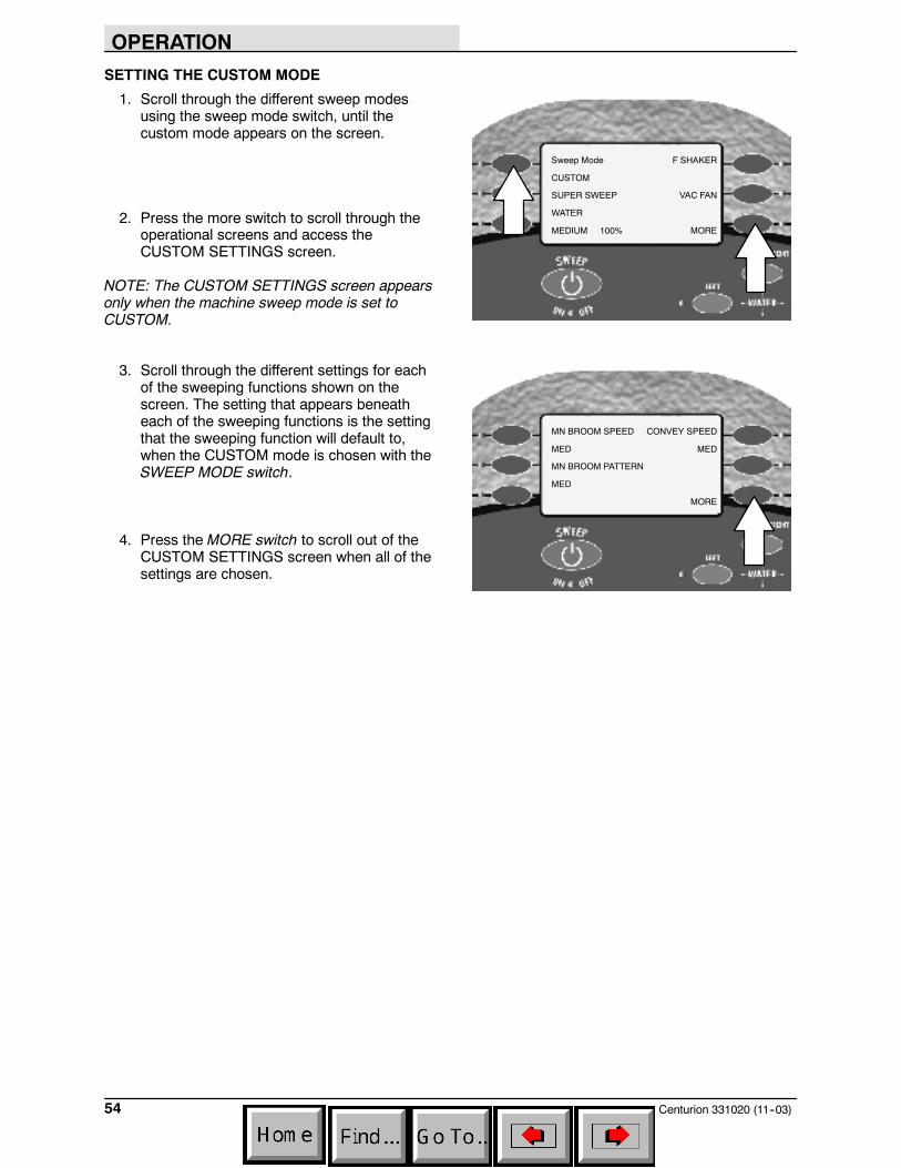
SETTING THE CUSTOM MODE
1. Scroll through the different sweep modesusing the sweep mode switch, until thecustom mode appears on the screen.
2. Press the more switch to scroll through theoperational screens and access theCUSTOM SETTINGS screen.
NOTE: The CUSTOM SETTINGS screen appearsonly when the machine sweep mode is set toCUSTOM.
3. Scroll through the different settings for eachof the sweeping functions shown on thescreen. The setting that appears beneatheach of the sweeping functions is the settingthat the sweeping function will default to,when the CUSTOM mode is chosen with theSWEEP MODE switch.
4. Press the MORE switch to scroll out of theCUSTOM SETTINGS screen when all of thesettings are chosen.
Sweep Mode
CUSTOM
SUPER SWEEP
WATER
MEDIUM 100%
F SHAKER
VAC FAN
MORE
MN BROOM SPEED
MED
MN BROOM PATTERN
MED
CONVEY SPEED
MED
MORE
OPERATION
55Centurion 331020 (11--03)
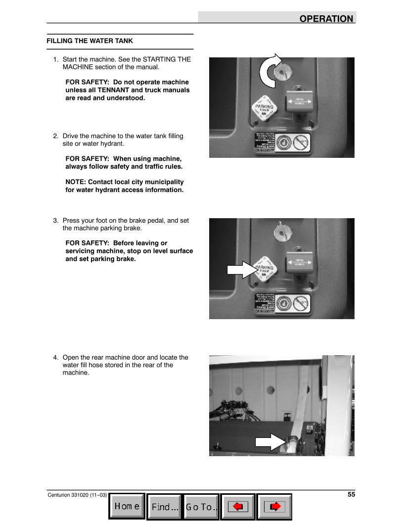
FILLING THE WATER TANK
1. Start the machine. See the STARTING THEMACHINE section of the manual.
FOR SAFETY: Do not operate machineunless all TENNANT and truck manualsare read and understood.
2. Drive the machine to the water tank fillingsite or water hydrant.
FOR SAFETY: When using machine,always follow safety and traffic rules.
NOTE: Contact local city municipalityfor water hydrant access information.
3. Press your foot on the brake pedal, and setthe machine parking brake.
FOR SAFETY: Before leaving orservicing machine, stop on level surfaceand set parking brake.
4. Open the rear machine door and locate thewater fill hose stored in the rear of themachine.

OPERATION
Centurion 331020 (11--03)56
5. Remove the hose from the rear of themachine. Connect the water hose to thewater valve or hydrant.
FOR SAFETY: Wear eye and earprotection when using pressurized airor water.
NOTE: Contact local city municipalityfor water hydrant access information.
NOTE: Flush the hydrant before filling the watertank.
NOTE: The hydrant wrench (option) is storednext to the water hose in the rear of the machine.
6. Fill the water tank.
FOR SAFETY: Wear eye and earprotection when using pressurized airor water.
7. Close the valve or hydrant when the tank isfull. Fold the water hose back into thestorage location. Place the hydrant wrench(option) back in the storage position next tothe hose.
8. Close the rear machine door.
OPERATION
57Centurion 331020 (11--03)
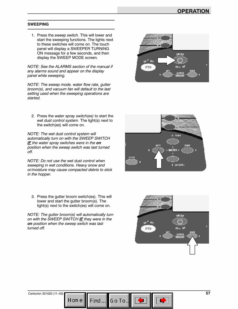
SWEEPING
1. Press the sweep switch. This will lower andstart the sweeping functions. The lights nextto these switches will come on. The touchpanel will display a SWEEPER TURNINGON message for a few seconds, and thendisplay the SWEEP MODE screen.
NOTE: See the ALARMS section of the manual ifany alarms sound and appear on the displaypanel while sweeping.
NOTE: The sweep mode, water flow rate, gutterbroom(s), and vacuum fan will default to the lastsetting used when the sweeping operations arestarted.
2. Press the water spray switch(es) to start thewet dust control system. The light(s) next tothe switch(es) will come on.
NOTE: The wet dust control system willautomatically turn on with the SWEEP SWITCHIF the water spray switches were in the onposition when the sweep switch was last turnedoff.
NOTE: Do not use the wet dust control whensweeping in wet conditions. Heavy snow andor/moisture may cause compacted debris to stickin the hopper.
3. Press the gutter broom switch(es). This willlower and start the gutter broom(s). Thelight(s) next to the switch(es) will come on.
NOTE: The gutter broom(s) will automatically turnon with the SWEEP SWITCH IF they were in theon position when the sweep switch was lastturned off.
OPERATION
Centurion 331020 (9--05)58
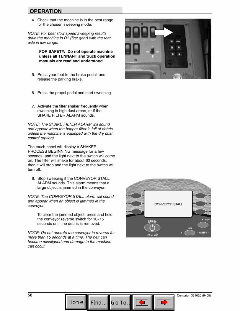
4. Check that the machine is in the best rangefor the chosen sweeping mode.
NOTE: For best slow speed sweeping results,drive the machine in D1 (first gear) with the rearaxle in low range.
FOR SAFETY: Do not operate machineunless all TENNANT and truck operationmanuals are read and understood.
5. Press your foot to the brake pedal, andrelease the parking brake.
6. Press the propel pedal and start sweeping.
7. Activate the filter shaker frequently whensweeping in high dust areas, or if theSHAKE FILTER ALARM sounds.
NOTE: The SHAKE FILTER ALARM will soundand appear when the hopper filter is full of debris,unless the machine is equipped with the dry dustcontrol (option).
The touch panel will display a SHAKERPROCESS BEGINNING message for a fewseconds, and the light next to the switch will comeon. The filter will shake for about 60 seconds,then it will stop and the light next to the switch willturn off.
8. Stop sweeping if the CONVEYOR STALLALARM sounds. This alarm means that alarge object is jammed in the conveyor.
NOTE: The CONVEYOR STALL alarm will soundand appear when an object is jammed in theconveyor.
To clear the jammed object, press and holdthe conveyor reverse switch for 10--15seconds until the debris is removed.
NOTE: Do not operate the conveyor in reverse formore than 15 seconds at a time. The belt canbecome misaligned and damage to the machinecan occur.
!CONVEYOR STALL!
OPERATION
59Centurion 331020 (11--03)
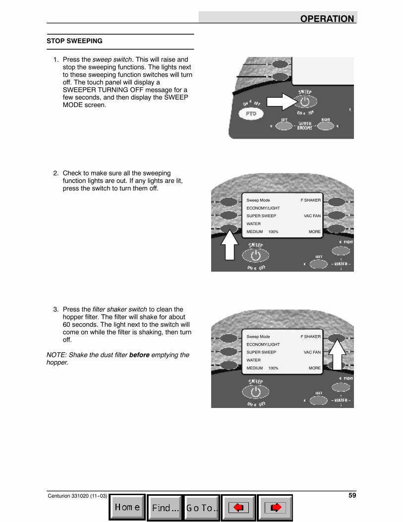
STOP SWEEPING
1. Press the sweep switch. This will raise andstop the sweeping functions. The lights nextto these sweeping function switches will turnoff. The touch panel will display aSWEEPER TURNING OFF message for afew seconds, and then display the SWEEPMODE screen.
2. Check to make sure all the sweepingfunction lights are out. If any lights are lit,press the switch to turn them off.
3. Press the filter shaker switch to clean thehopper filter. The filter will shake for about60 seconds. The light next to the switch willcome on while the filter is shaking, then turnoff.
NOTE: Shake the dust filter before emptying thehopper.
Sweep Mode
ECONOMY/LIGHT
SUPER SWEEP
WATER
MEDIUM 100%
F SHAKER
VAC FAN
MORE
Sweep Mode
ECONOMY/LIGHT
SUPER SWEEP
WATER
MEDIUM 100%
F SHAKER
VAC FAN
MORE

OPERATION
Centurion 331020 (11--03)60
EMPTYING THE HOPPER
1. Drive the machine slowly to the debriscollection site or debris container. Make surethe machine is on level ground beforedumping the hopper.
NOTE: The MACHINE NOT LEVEL ALARM willsound and appear if a hopper lift is attempted andthe machine is on an incline that is unsafe for highdumping.
FOR SAFETY: When using machine,only dump the hopper on a levelsurface.
2. Press and hold the brake pedal with yourfoot. Place the machine in neutral, thenengage the parking brake.
NOTE: The ACTIVATE PARK BRAKE ALARM willsound and appear if a hopper lift is attempted andthe parking brake is not set.
3. Press and hold the hopper up switch untilthe hopper is at the desired raised position,then release the switch. An audible alarmwill sound while the hopper is moving.
WARNING: High dump verticalclearance. Stay clear of overheadobstructions and power lines.
NOTE: The ACTIVATE PARK BRAKE ALARM willsound and appear if a hopper lift is attempted andthe parking brake is not set.
FOR SAFETY: Do not move machinewhen hopper is raised.
HOPPER UP
HOPPER DOWN
F SHAKER
HOPPER DUMP
HOPPER HOME
MORE
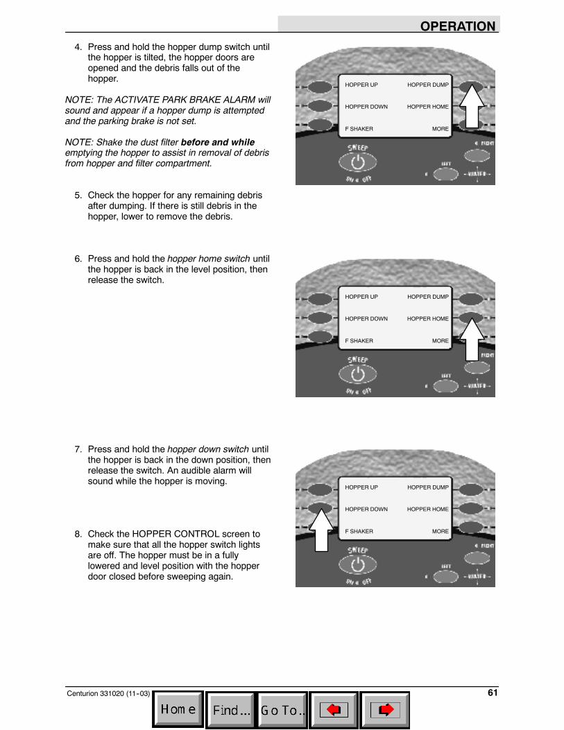
OPERATION
61Centurion 331020 (11--03)
4. Press and hold the hopper dump switch untilthe hopper is tilted, the hopper doors areopened and the debris falls out of thehopper.
NOTE: The ACTIVATE PARK BRAKE ALARM willsound and appear if a hopper dump is attemptedand the parking brake is not set.
NOTE: Shake the dust filter before and whileemptying the hopper to assist in removal of debrisfrom hopper and filter compartment.
5. Check the hopper for any remaining debrisafter dumping. If there is still debris in thehopper, lower to remove the debris.
6. Press and hold the hopper home switch untilthe hopper is back in the level position, thenrelease the switch.
7. Press and hold the hopper down switch untilthe hopper is back in the down position, thenrelease the switch. An audible alarm willsound while the hopper is moving.
8. Check the HOPPER CONTROL screen tomake sure that all the hopper switch lightsare off. The hopper must be in a fullylowered and level position with the hopperdoor closed before sweeping again.
HOPPER UP
HOPPER DOWN
F SHAKER
HOPPER DUMP
HOPPER HOME
MORE
HOPPER UP
HOPPER DOWN
F SHAKER
HOPPER DUMP
HOPPER HOME
MORE
HOPPER UP
HOPPER DOWN
F SHAKER
HOPPER DUMP
HOPPER HOME
MORE
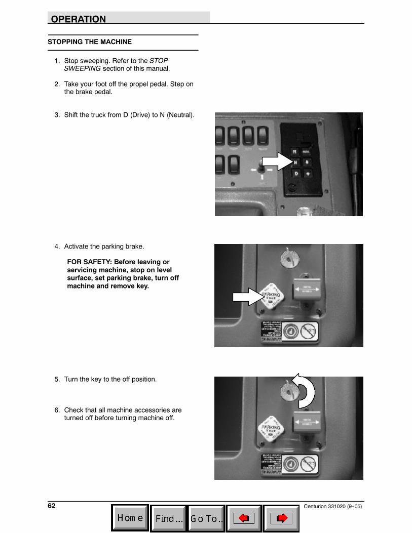
OPERATION
Centurion 331020 (9--05)62
STOPPING THE MACHINE
1. Stop sweeping. Refer to the STOPSWEEPING section of this manual.
2. Take your foot off the propel pedal. Step onthe brake pedal.
3. Shift the truck from D (Drive) to N (Neutral).
4. Activate the parking brake.
FOR SAFETY: Before leaving orservicing machine, stop on levelsurface, set parking brake, turn offmachine and remove key.
5. Turn the key to the off position.
6. Check that all machine accessories areturned off before turning machine off.
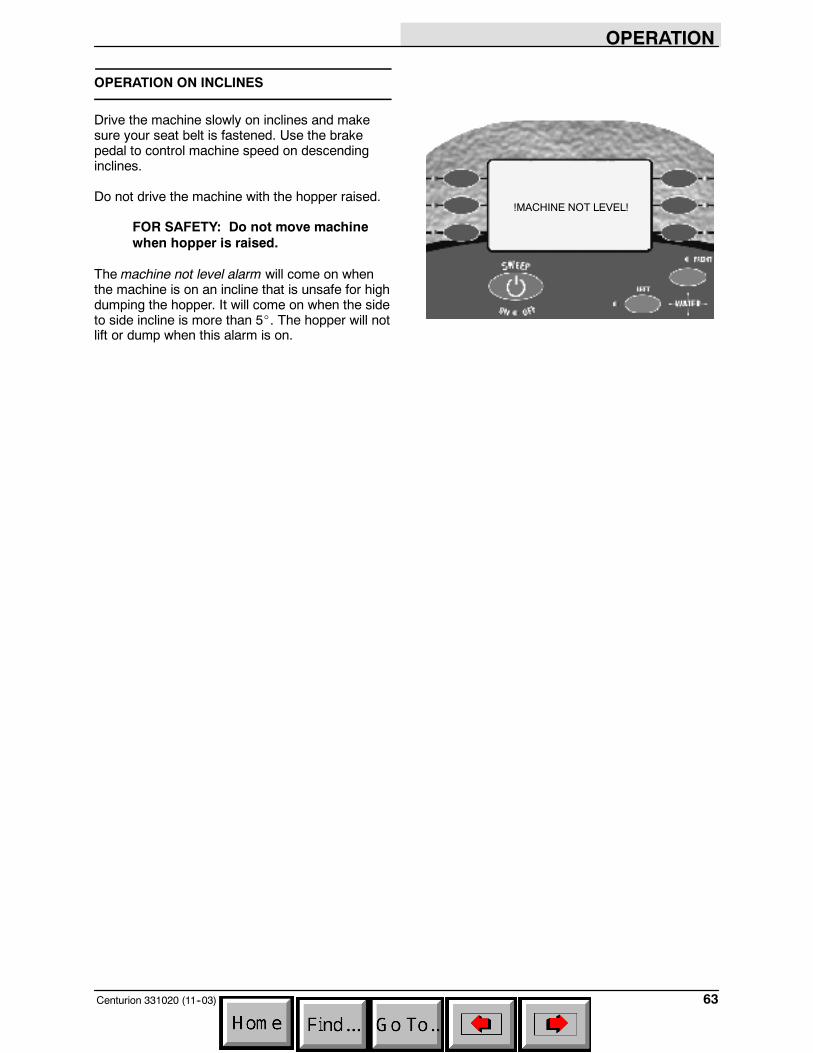
OPERATION
63Centurion 331020 (11--03)
OPERATION ON INCLINES
Drive the machine slowly on inclines and makesure your seat belt is fastened. Use the brakepedal to control machine speed on descendinginclines.
Do not drive the machine with the hopper raised.
FOR SAFETY: Do not move machinewhen hopper is raised.
The machine not level alarm will come on whenthe machine is on an incline that is unsafe for highdumping the hopper. It will come on when the sideto side incline is more than 5_. The hopper will notlift or dump when this alarm is on.
!MACHINE NOT LEVEL!
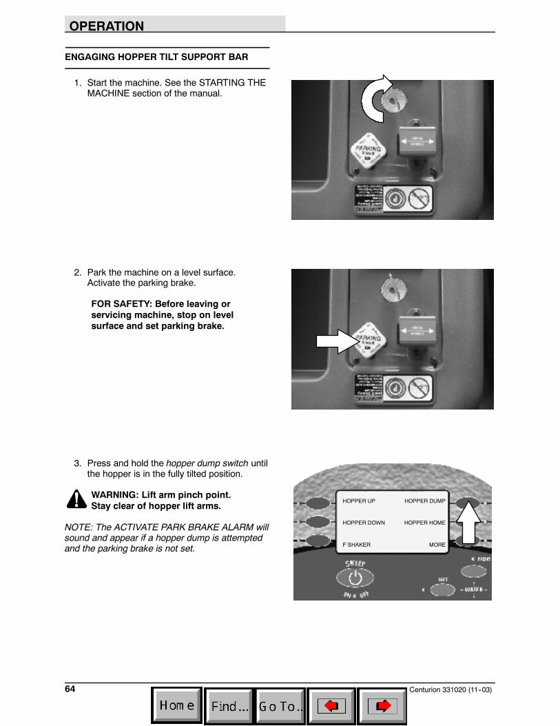
OPERATION
Centurion 331020 (11--03)64
ENGAGING HOPPER TILT SUPPORT BAR
1. Start the machine. See the STARTING THEMACHINE section of the manual.
2. Park the machine on a level surface.Activate the parking brake.
FOR SAFETY: Before leaving orservicing machine, stop on levelsurface and set parking brake.
3. Press and hold the hopper dump switch untilthe hopper is in the fully tilted position.
WARNING: Lift arm pinch point.Stay clear of hopper lift arms.
NOTE: The ACTIVATE PARK BRAKE ALARM willsound and appear if a hopper dump is attemptedand the parking brake is not set.
HOPPER UP
HOPPER DOWN
F SHAKER
HOPPER DUMP
HOPPER HOME
MORE
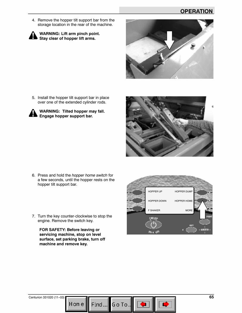
OPERATION
65Centurion 331020 (11--03)
4. Remove the hopper tilt support bar from thestorage location in the rear of the machine.
WARNING: Lift arm pinch point.Stay clear of hopper lift arms.
5. Install the hopper tilt support bar in placeover one of the extended cylinder rods.
WARNING: Tilted hopper may fall.Engage hopper support bar.
6. Press and hold the hopper home switch fora few seconds, until the hopper rests on thehopper tilt support bar.
7. Turn the key counter-clockwise to stop theengine. Remove the switch key.
FOR SAFETY: Before leaving orservicing machine, stop on levelsurface, set parking brake, turn offmachine and remove key.
HOPPER UP
HOPPER DOWN
F SHAKER
HOPPER DUMP
HOPPER HOME
MORE
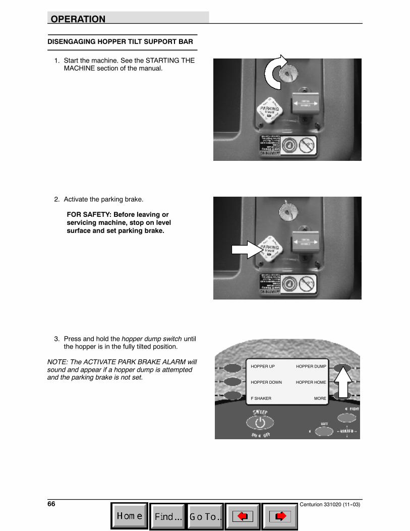
OPERATION
Centurion 331020 (11--03)66
DISENGAGING HOPPER TILT SUPPORT BAR
1. Start the machine. See the STARTING THEMACHINE section of the manual.
2. Activate the parking brake.
FOR SAFETY: Before leaving orservicing machine, stop on levelsurface and set parking brake.
3. Press and hold the hopper dump switch untilthe hopper is in the fully tilted position.
NOTE: The ACTIVATE PARK BRAKE ALARM willsound and appear if a hopper dump is attemptedand the parking brake is not set.
HOPPER UP
HOPPER DOWN
F SHAKER
HOPPER DUMP
HOPPER HOME
MORE
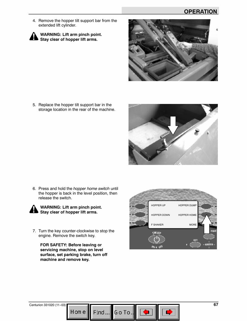
OPERATION
67Centurion 331020 (11--03)
4. Remove the hopper tilt support bar from theextended lift cylinder.
WARNING: Lift arm pinch point.Stay clear of hopper lift arms.
5. Replace the hopper tilt support bar in thestorage location in the rear of the machine.
6. Press and hold the hopper home switch untilthe hopper is back in the level position, thenrelease the switch.
WARNING: Lift arm pinch point.Stay clear of hopper lift arms.
7. Turn the key counter-clockwise to stop theengine. Remove the switch key.
FOR SAFETY: Before leaving orservicing machine, stop on levelsurface, set parking brake, turn offmachine and remove key.
HOPPER UP
HOPPER DOWN
F SHAKER
HOPPER DUMP
HOPPER HOME
MORE

OPERATION
Centurion 331020 (11--03)68
ENGAGING HOPPER LIFT SUPPORT BARS
1. Start the machine. See the STARTING THEMACHINE section of the manual.
2. Park the machine on a level surface.Activate the parking brake.
FOR SAFETY: Before leaving orservicing machine, stop on levelsurface and set parking brake.
3. Press and hold the hopper up switch untilthe hopper is in the fully raised position, thenrelease the switch. An audible alarm willsound while the hopper is moving.
WARNING: Lift arm pinch point.Stay clear of hopper lift arms.
WARNING: High dump verticalclearance. Stay clear of overheadobstructions and power lines.
NOTE: The ACTIVATE PARK BRAKE ALARM willsound and appear if a hopper lift is attempted andthe parking brake is not set.
HOPPER UP
HOPPER DOWN
F SHAKER
HOPPER DUMP
HOPPER HOME
MORE
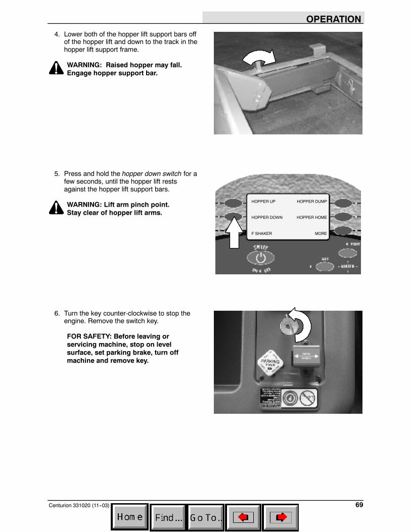
OPERATION
69Centurion 331020 (11--03)
4. Lower both of the hopper lift support bars offof the hopper lift and down to the track in thehopper lift support frame.
WARNING: Raised hopper may fall.Engage hopper support bar.
5. Press and hold the hopper down switch for afew seconds, until the hopper lift restsagainst the hopper lift support bars.
WARNING: Lift arm pinch point.Stay clear of hopper lift arms.
6. Turn the key counter-clockwise to stop theengine. Remove the switch key.
FOR SAFETY: Before leaving orservicing machine, stop on levelsurface, set parking brake, turn offmachine and remove key.
HOPPER UP
HOPPER DOWN
F SHAKER
HOPPER DUMP
HOPPER HOME
MORE
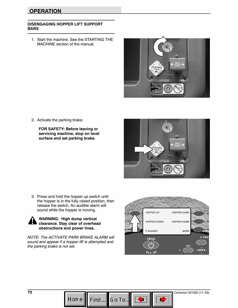
OPERATION
Centurion 331020 (11--03)70
DISENGAGING HOPPER LIFT SUPPORTBARS
1. Start the machine. See the STARTING THEMACHINE section of the manual.
2. Activate the parking brake.
FOR SAFETY: Before leaving orservicing machine, stop on levelsurface and set parking brake.
3. Press and hold the hopper up switch untilthe hopper is in the fully raised position, thenrelease the switch. An audible alarm willsound while the hopper is moving.
WARNING: High dump verticalclearance. Stay clear of overheadobstructions and power lines.
NOTE: The ACTIVATE PARK BRAKE ALARM willsound and appear if a hopper lift is attempted andthe parking brake is not set.
HOPPER UP
HOPPER DOWN
F SHAKER
HOPPER DUMP
HOPPER HOME
MORE

OPERATION
71Centurion 331020 (11--03)
4. Raise both of the hopper lift support bars outof the hopper frame and rest them up on thehopper lift.
WARNING: Lift arm pinch point.Stay clear of hopper lift arms.
5. Press and hold the hopper down switch untilthe hopper is back in the down position, thenrelease the switch. An audible alarm willsound while the hopper is moving.
WARNING: Lift arm pinch point.Stay clear of hopper lift arms.
6. Turn the key counter-clockwise to stop theengine. Remove the switch key.
FOR SAFETY: Before leaving orservicing machine, stop on levelsurface, set parking brake, turn offmachine and remove key.
HOPPER UP
HOPPER DOWN
F SHAKER
HOPPER DUMP
HOPPER HOME
MORE

OPERATION
Centurion 331020 (11--03)72
MACHINE TROUBLESHOOTING
Problem Cause Remedy
Machine does not start Engine air heater not heated Heat engine air heater
Fuel tank empty Fill fuel tank
Engine temperature too high Check coolant level
Excessive dusting Brush skirts and dust seals worn,damaged, out of adjustment
Replace or adjust brush skirts ordust seals
Hopper dust filter clogged Shake and/or clean or replacedust filter
Vacuum fan not on Turn vacuum fan on
Vacuum fan failure Contact service personnel
Water tank empty Fill water tank
Wet dust water pump or valvesnot turned on
Turn on the wet dust control waterpump and valves
Sweep switch will not activate Hopper not fully lowered Lower hopper fully
Engine RPM to high Lower RPM < 950 RPM
Hydraulic fluid level low Check hydraulic fluid level
Hopper will not lift or tilt Machine on too steep of an incline Move machine to a level surface
Park or service brake not applied Apply park or service brake
Hopper overloaded Remove debris from hopper
Hydraulic fluid level low Check hydraulic fluid level
Machine will not propel Brake pressure too low Contact service personnel
Parking brake on Release parking brake
Pushbutton range selector in N(neutral)
Change pushbutton range selectorfron N (neutral) to D (drive)
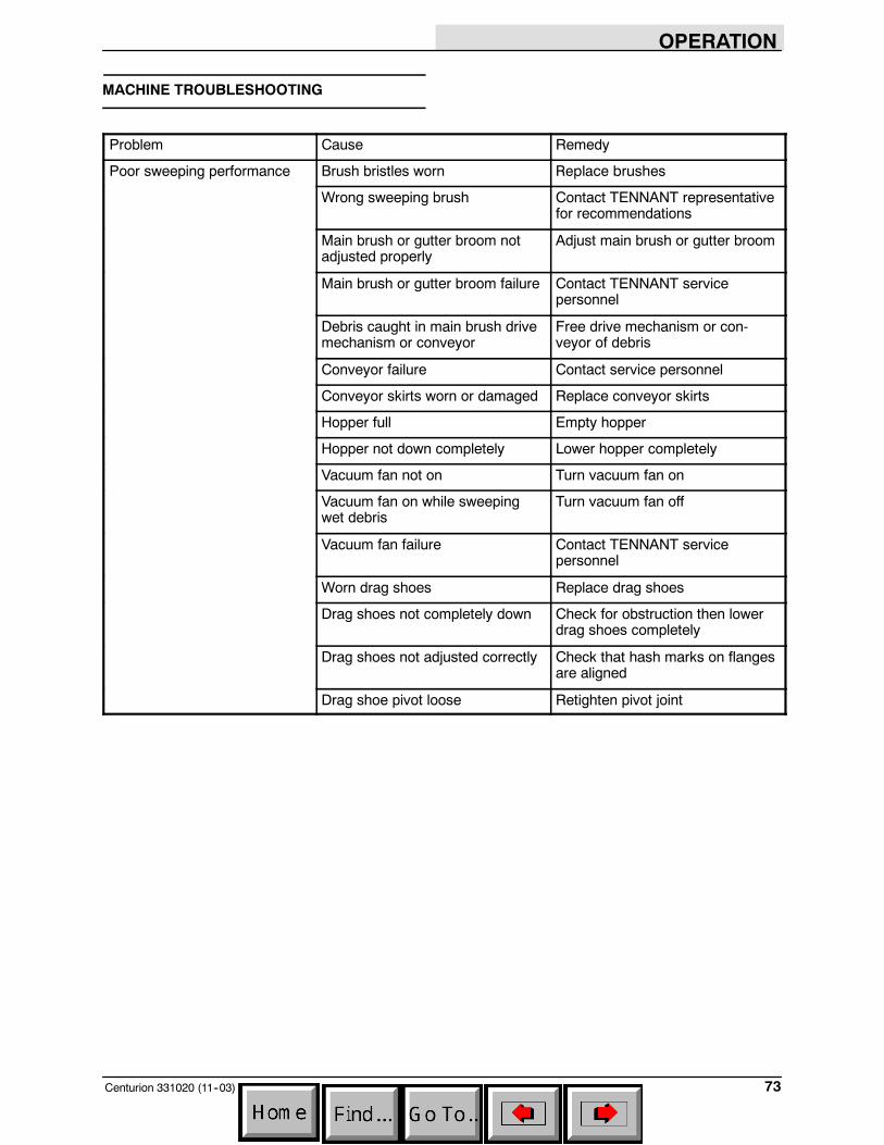
OPERATION
73Centurion 331020 (11--03)
MACHINE TROUBLESHOOTING
Problem Cause Remedy
Poor sweeping performance Brush bristles worn Replace brushes
Wrong sweeping brush Contact TENNANT representativefor recommendations
Main brush or gutter broom notadjusted properly
Adjust main brush or gutter broom
Main brush or gutter broom failure Contact TENNANT servicepersonnel
Debris caught in main brush drivemechanism or conveyor
Free drive mechanism or con-veyor of debris
Conveyor failure Contact service personnel
Conveyor skirts worn or damaged Replace conveyor skirts
Hopper full Empty hopper
Hopper not down completely Lower hopper completely
Vacuum fan not on Turn vacuum fan on
Vacuum fan on while sweepingwet debris
Turn vacuum fan off
Vacuum fan failure Contact TENNANT servicepersonnel
Worn drag shoes Replace drag shoes
Drag shoes not completely down Check for obstruction then lowerdrag shoes completely
Drag shoes not adjusted correctly Check that hash marks on flangesare aligned
Drag shoe pivot loose Retighten pivot joint
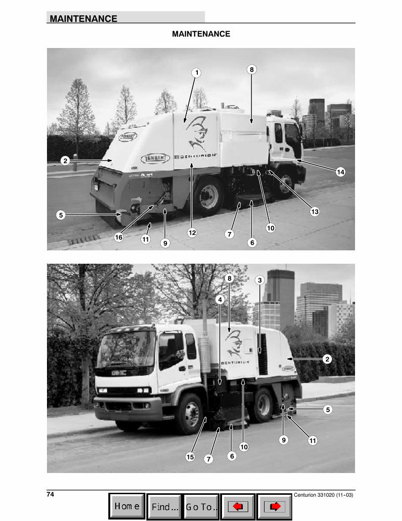
MAINTENANCE
Centurion 331020 (11--03)74
MAINTENANCE
1
3
4
5
6
67
7
8
8
5
10
10
2
2
9
9
11
1112
13
14
15
16
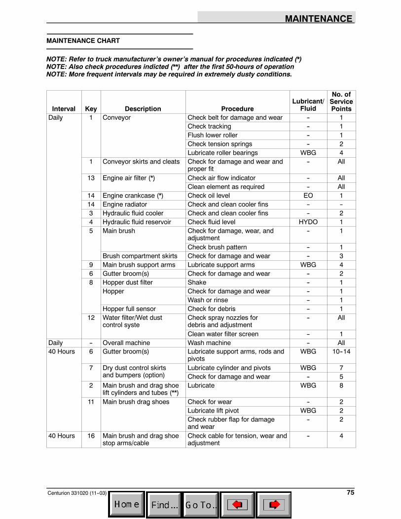
MAINTENANCE
75Centurion 331020 (11--03)
MAINTENANCE CHART
NOTE: Refer to truck manufacturer’s owner’s manual for procedures indicated (*)NOTE: Also check procedures indicted (**) after the first 50-hours of operationNOTE: More frequent intervals may be required in extremely dusty conditions.
Interval Key Description ProcedureLubricant/
Fluid
No. ofServicePoints
Daily 1 Conveyor Check belt for damage and wear -- 1y yCheck tracking -- 1Flush lower roller -- 1Check tension springs -- 2Lubricate roller bearings WBG 4
1 Conveyor skirts and cleats Check for damage and wear andproper fit
-- All
13 Engine air filter (*) Check air flow indicator -- Allg ( )Clean element as required -- All
14 Engine crankcase (*) Check oil level EO 114 Engine radiator Check and clean cooler fins -- --3 Hydraulic fluid cooler Check and clean cooler fins -- 24 Hydraulic fluid reservoir Check fluid level HYDO 15 Main brush Check for damage, wear, and
adjustment-- 1
Check brush pattern -- 1Brush compartment skirts Check for damage and wear -- 3
9 Main brush support arms Lubricate support arms WBG 46 Gutter broom(s) Check for damage and wear -- 28 Hopper dust filter Shake -- 1
Hopper Check for damage and wear -- 1ppWash or rinse -- 1
Hopper full sensor Check for debris -- 112 Water filter/Wet dust
control systeCheck spray nozzles fordebris and adjustment
-- Ally
Clean water filter screen -- 1Daily -- Overall machine Wash machine -- All40 Hours 6 Gutter broom(s) Lubricate support arms, rods and
pivotsWBG 10--14
7 Dry dust control skirts Lubricate cylinder and pivots WBG 7yand bumpers (option) Check for damage and wear -- 5
2 Main brush and drag shoelift cylinders and tubes (**)
Lubricate WBG 8
11 Main brush drag shoes Check for wear -- 2gLubricate lift pivot WBG 2Check rubber flap for damageand wear
-- 2
40 Hours 16 Main brush and drag shoestop arms/cable
Check cable for tension, wear andadjustment
-- 4

MAINTENANCE
Centurion 331020 (7--04)76
Interval Key Description ProcedureLubricant/
Fluid
No. ofServicePoints
100 Hours 1 Conveyor Lubricate lift pivots and cylinders WBG 10yCheck conveyor drag shoe heightadjustment
-- 2
14 Engine crankcase (*) Change oil and filter EO 15 Brush compartment, con-
veyor and hopper sealsCheck for damage or wear -- All
7 Gutter broom dry dustcontrol skirt pivots (option)
Lubricate -- All
15 Propulsion shafts Lubricate slip joints WBG 2pCheck joints for wear -- 2
10 Conveyor tilt cylinder (**) Lubricate WBG 210 Hopper lift/tilt Lubricate WBG 2
200 Hours 9 Main brush Lubricate idler bearing WBG 1-- Hydraulic hoses Check for damage and wear -- All12 Wet dust control system Check water tank for damage -- 1y
Check water pump -- 1Check water hoses for wear -- AllCheck water filter screen for dam-age
-- 1
500 Hours -- Transmission (*) Initial transmission fluid change SPL 1800 Hours 4 Hydraulic reservoir Replace filler cap -- 1y
Change hydraulic fluid(non--synthetic)
HYDO 1
3 Hydraulic fluid filter Change filter element -- 13 Hydraulic pump load
sense filterCheck and/or change filterelement
-- 2
12 Wet dust control system Check water hoses and clampsfor leakage or damage
-- 1
3000Hours
-- Transmission (*) Transmission fluid change(when using synthetic fluid)
SPL 1
4 Hydraulic reservoir Change hydraulic fluid (synthetic) HYDO 1
LUBRICANT/FLUIDEO Engine oil, SAE--CI--4 or CH--4 rated.SPL Transmission fluid (synthetic TranSyndt/TES 295 Fluid). . .HYDO TENNANT or approved hydraulic fluid.WBG Waterproof bearing grease (TENNANT part no. 765819). .
NOTE: Themaintenance chart covers sweeper maintenance only. Refer to Chasis and Transmissionowner’s manuals for recommended service intervals of chassis, engine and transmission.
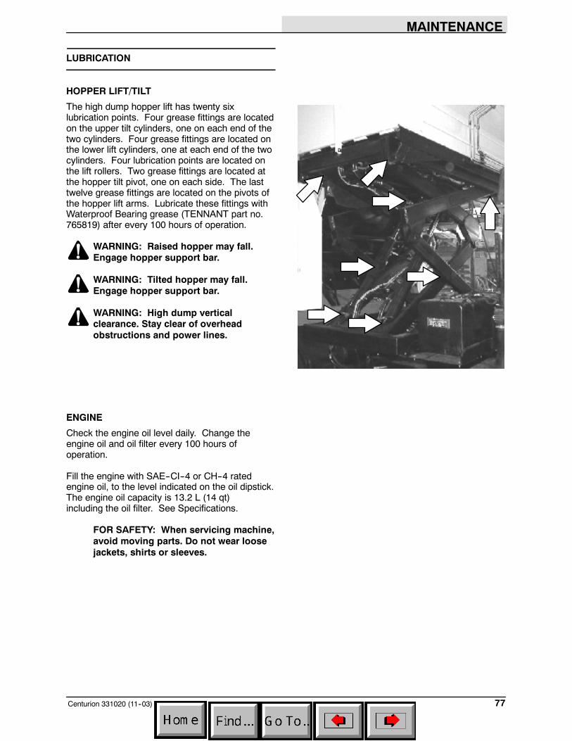
MAINTENANCE
77Centurion 331020 (11--03)
LUBRICATION
HOPPER LIFT/TILT
The high dump hopper lift has twenty sixlubrication points. Four grease fittings are locatedon the upper tilt cylinders, one on each end of thetwo cylinders. Four grease fittings are located onthe lower lift cylinders, one at each end of the twocylinders. Four lubrication points are located onthe lift rollers. Two grease fittings are located atthe hopper tilt pivot, one on each side. The lasttwelve grease fittings are located on the pivots ofthe hopper lift arms. Lubricate these fittings withWaterproof Bearing grease (TENNANT part no.765819) after every 100 hours of operation.
WARNING: Raised hopper may fall.Engage hopper support bar.
WARNING: Tilted hopper may fall.Engage hopper support bar.
WARNING: High dump verticalclearance. Stay clear of overheadobstructions and power lines.
ENGINE
Check the engine oil level daily. Change theengine oil and oil filter every 100 hours ofoperation.
Fill the engine with SAE--CI--4 or CH--4 ratedengine oil, to the level indicated on the oil dipstick.The engine oil capacity is 13.2 L (14 qt)including the oil filter. See Specifications.
FOR SAFETY: When servicing machine,avoid moving parts. Do not wear loosejackets, shirts or sleeves.
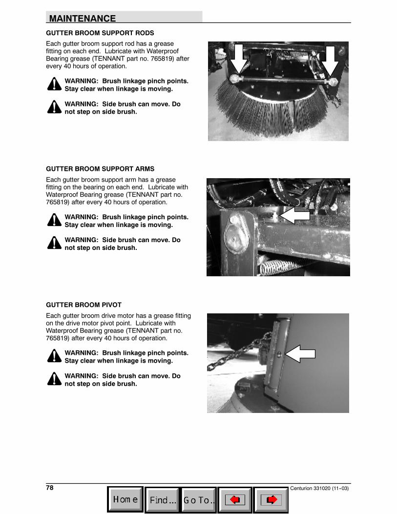
MAINTENANCE
Centurion 331020 (11--03)78
GUTTER BROOM SUPPORT RODS
Each gutter broom support rod has a greasefitting on each end. Lubricate with WaterproofBearing grease (TENNANT part no. 765819) afterevery 40 hours of operation.
WARNING: Brush linkage pinch points.Stay clear when linkage is moving.
WARNING: Side brush can move. Donot step on side brush.
GUTTER BROOM SUPPORT ARMS
Each gutter broom support arm has a greasefitting on the bearing on each end. Lubricate withWaterproof Bearing grease (TENNANT part no.765819) after every 40 hours of operation.
WARNING: Brush linkage pinch points.Stay clear when linkage is moving.
WARNING: Side brush can move. Donot step on side brush.
GUTTER BROOM PIVOT
Each gutter broom drive motor has a grease fittingon the drive motor pivot point. Lubricate withWaterproof Bearing grease (TENNANT part no.765819) after every 40 hours of operation.
WARNING: Brush linkage pinch points.Stay clear when linkage is moving.
WARNING: Side brush can move. Donot step on side brush.

MAINTENANCE
79Centurion 331020 (11--03)
DUST CONTROL SKIRT CYLINDER (OPTION)
The gutter broom dust skirt cylinder has alubrication point on one end. Lubricate withWaterproof Bearing grease (TENNANT part no.765819) after every 40 hours of operation.
WARNING: Brush linkage pinch points.Stay clear when linkage is moving.
DUST CONTROL SKIRT PIVOTS (OPTION)
The gutter broom dust control skirt shaft has onegrease fitting on each end of the shaft. Lubricatewith Waterproof Bearing grease (TENNANT partno. 765819) after every 40 hours of operation.
WARNING: Brush linkage pinch points.Stay clear when linkage is moving.
DUST CONTROL BUMPER PIVOTS (OPTION)
The gutter broom dust control bumpers have onegrease fitting on the inside of each pivot.Lubricate with Waterproof Bearing grease(TENNANT part no. 765819) after every 40 hoursof operation.
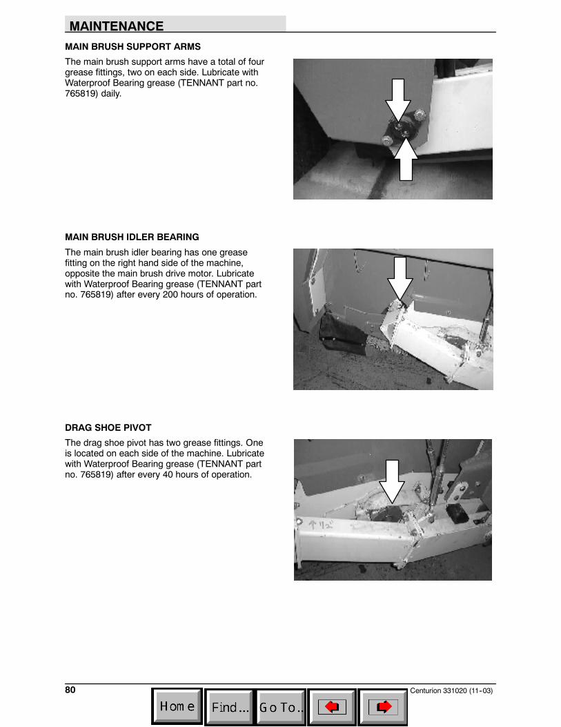
MAINTENANCE
Centurion 331020 (11--03)80
MAIN BRUSH SUPPORT ARMS
The main brush support arms have a total of fourgrease fittings, two on each side. Lubricate withWaterproof Bearing grease (TENNANT part no.765819) daily.
MAIN BRUSH IDLER BEARING
The main brush idler bearing has one greasefitting on the right hand side of the machine,opposite the main brush drive motor. Lubricatewith Waterproof Bearing grease (TENNANT partno. 765819) after every 200 hours of operation.
DRAG SHOE PIVOT
The drag shoe pivot has two grease fittings. Oneis located on each side of the machine. Lubricatewith Waterproof Bearing grease (TENNANT partno. 765819) after every 40 hours of operation.
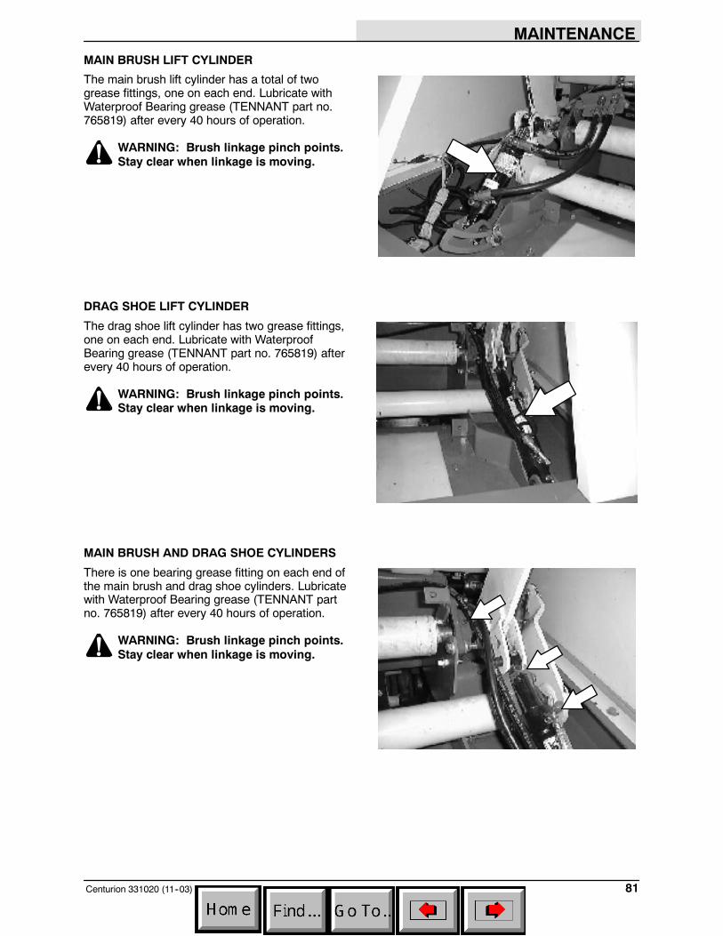
MAINTENANCE
81Centurion 331020 (11--03)
MAIN BRUSH LIFT CYLINDER
The main brush lift cylinder has a total of twogrease fittings, one on each end. Lubricate withWaterproof Bearing grease (TENNANT part no.765819) after every 40 hours of operation.
WARNING: Brush linkage pinch points.Stay clear when linkage is moving.
DRAG SHOE LIFT CYLINDER
The drag shoe lift cylinder has two grease fittings,one on each end. Lubricate with WaterproofBearing grease (TENNANT part no. 765819) afterevery 40 hours of operation.
WARNING: Brush linkage pinch points.Stay clear when linkage is moving.
MAIN BRUSH AND DRAG SHOE CYLINDERS
There is one bearing grease fitting on each end ofthe main brush and drag shoe cylinders. Lubricatewith Waterproof Bearing grease (TENNANT partno. 765819) after every 40 hours of operation.
WARNING: Brush linkage pinch points.Stay clear when linkage is moving.

MAINTENANCE
Centurion 331020 (11--03)82
CONVEYOR BEARINGS
The four conveyor bearing lubrication points aremounted on the right side of the conveyor. Theydistribute grease to the conveyor bearings viaplastic feed tubes.
Lubricate each bearing daily with WaterproofBearing grease (TENNANT part no. 765819).
WARNING: Conveyor throws debris.Conveyor pinch point. Stay clear whenin operation.
CONVEYOR LIFT PIVOTS
There is one grease fitting on each end of theconveyor lift shaft. Lubricate with WaterproofBearing grease (TENNANT part no. 765819) afterevery 100 hours of operation.
WARNING: Conveyor throws debris.Conveyor pinch point. Stay clear whenin operation.
CONVEYOR LIFT CYLINDERS
The two conveyor lift cylinders each have twogrease fittings, one at each end of each cylinder.There is also one grease fitting above and onegrease fitting below each lift cylinder. Lubricatewith Waterproof Bearing grease (TENNANT partno. 765819) after every 100 hours of operation.
WARNING: Conveyor throws debris.Conveyor pinch point. Stay clear whenin operation.
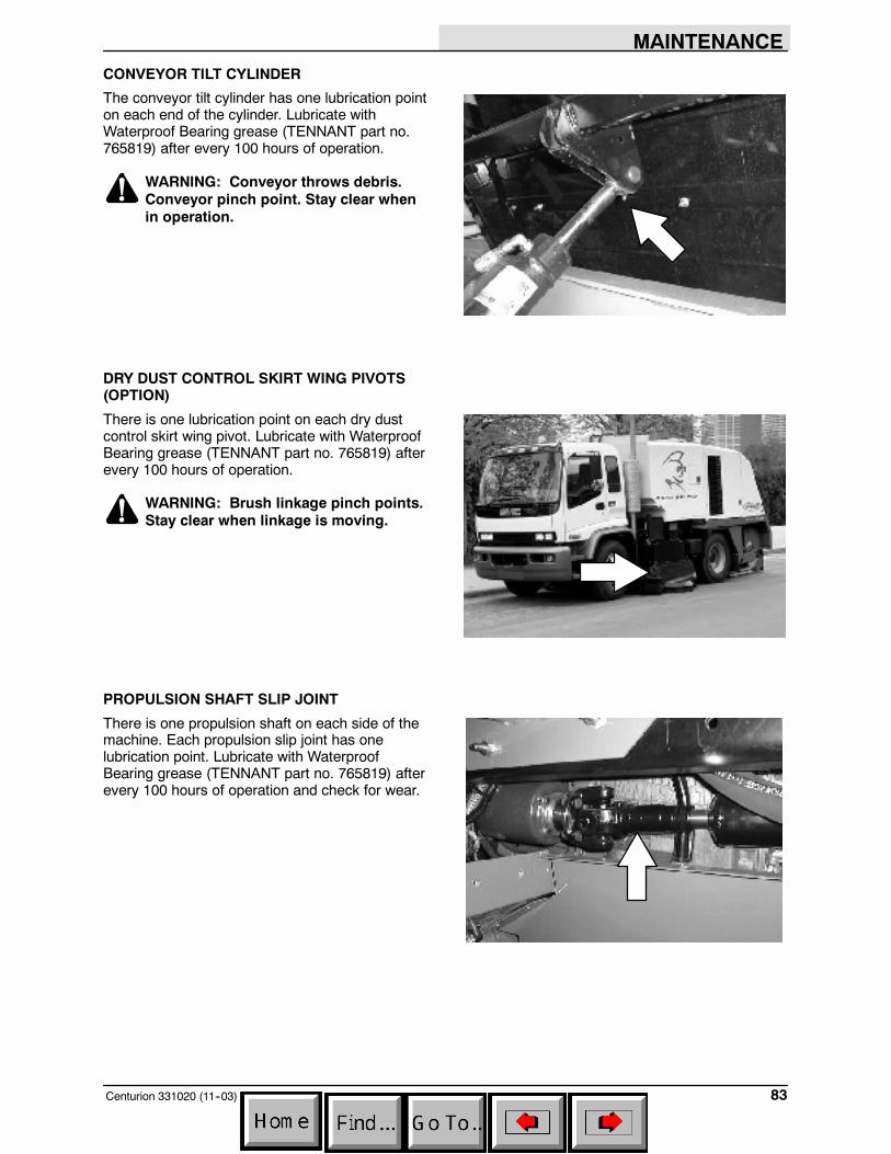
MAINTENANCE
83Centurion 331020 (11--03)
CONVEYOR TILT CYLINDER
The conveyor tilt cylinder has one lubrication pointon each end of the cylinder. Lubricate withWaterproof Bearing grease (TENNANT part no.765819) after every 100 hours of operation.
WARNING: Conveyor throws debris.Conveyor pinch point. Stay clear whenin operation.
DRY DUST CONTROL SKIRT WING PIVOTS(OPTION)
There is one lubrication point on each dry dustcontrol skirt wing pivot. Lubricate with WaterproofBearing grease (TENNANT part no. 765819) afterevery 100 hours of operation.
WARNING: Brush linkage pinch points.Stay clear when linkage is moving.
PROPULSION SHAFT SLIP JOINT
There is one propulsion shaft on each side of themachine. Each propulsion slip joint has onelubrication point. Lubricate with WaterproofBearing grease (TENNANT part no. 765819) afterevery 100 hours of operation and check for wear.
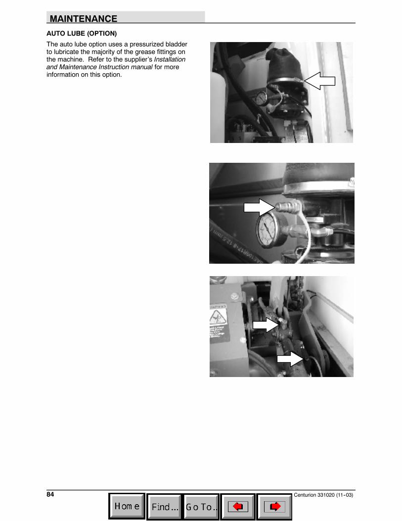
MAINTENANCE
Centurion 331020 (11--03)84
AUTO LUBE (OPTION)
The auto lube option uses a pressurized bladderto lubricate the majority of the grease fittings onthe machine. Refer to the supplier’s Installationand Maintenance Instruction manual for moreinformation on this option.
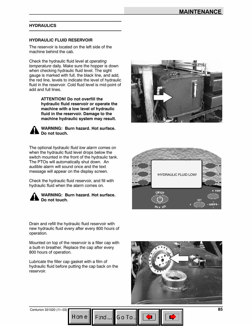
MAINTENANCE
85Centurion 331020 (11--03)
HYDRAULICS
HYDRAULIC FLUID RESERVOIR
The reservoir is located on the left side of themachine behind the cab.
Check the hydraulic fluid level at operatingtemperature daily. Make sure the hopper is downwhen checking hydraulic fluid level. The sightgauge is marked with full, the black line, and add,the red line, levels to indicate the level of hydraulicfluid in the reservoir. Cold fluid level is mid-point ofadd and full lines.
ATTENTION! Do not overfill thehydraulic fluid reservoir or operate themachine with a low level of hydraulicfluid in the reservoir. Damage to themachine hydraulic system may result.
WARNING: Burn hazard. Hot surface.Do not touch.
The optional hydraulic fluid low alarm comes onwhen the hydraulic fluid level drops below theswitch mounted in the front of the hydraulic tank.The PTOs will automatically shut down. Anaudible alarm will sound once and the textmessage will appear on the display screen.
Check the hydraulic fluid reservoir, and fill withhydraulic fluid when the alarm comes on.
WARNING: Burn hazard. Hot surface.Do not touch.
Drain and refill the hydraulic fluid reservoir withnew hydraulic fluid every after every 800 hours ofoperation.
Mounted on top of the reservoir is a filler cap witha built-in breather. Replace the cap after every800 hours of operation.
Lubricate the filler cap gasket with a film ofhydraulic fluid before putting the cap back on thereservoir.
!HYDRAULIC FLUID LOW!
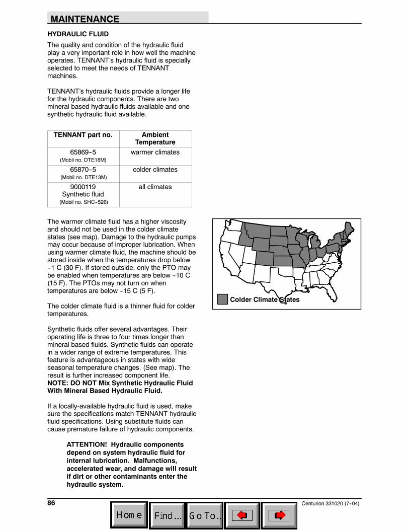
MAINTENANCE
Centurion 331020 (7--04)86
HYDRAULIC FLUID
The quality and condition of the hydraulic fluidplay a very important role in how well the machineoperates. TENNANT’s hydraulic fluid is speciallyselected to meet the needs of TENNANTmachines.
TENNANT’s hydraulic fluids provide a longer lifefor the hydraulic components. There are twomineral based hydraulic fluids available and onesynthetic hydraulic fluid available.
TENNANT part no. AmbientTemperature
65869--5(Mobil no. DTE18M)
warmer climates
65870--5(Mobil no. DTE13M)
colder climates
9000119Synthetic fluid(Mobil no. SHC--526)
all climates
The warmer climate fluid has a higher viscosityand should not be used in the colder climatestates (see map). Damage to the hydraulic pumpsmay occur because of improper lubrication. Whenusing warmer climate fluid, the machine should bestored inside when the temperatures drop below--1 C (30 F). If stored outside, only the PTO maybe enabled when temperatures are below --10 C(15 F). The PTOs may not turn on whentemperatures are below --15 C (5 F).
The colder climate fluid is a thinner fluid for coldertemperatures.
Synthetic fluids offer several advantages. Theiroperating life is three to four times longer thanmineral based fluids. Synthetic fluids can operatein a wider range of extreme temperatures. Thisfeature is advantageous in states with wideseasonal temperature changes. (See map). Theresult is further increased component life.NOTE: DO NOT Mix Synthetic Hydraulic FluidWith Mineral Based Hydraulic Fluid.
If a locally-available hydraulic fluid is used, makesure the specifications match TENNANT hydraulicfluid specifications. Using substitute fluids cancause premature failure of hydraulic components.
ATTENTION! Hydraulic componentsdepend on system hydraulic fluid forinternal lubrication. Malfunctions,accelerated wear, and damage will resultif dirt or other contaminants enter thehydraulic system.
Colder Climate States
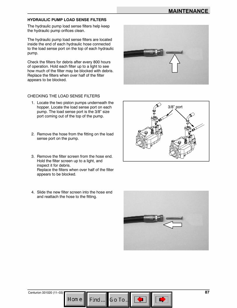
MAINTENANCE
87Centurion 331020 (11--03)
HYDRAULIC PUMP LOAD SENSE FILTERS
The hydraulic pump load sense filters help keepthe hydraulic pump orifices clean.
The hydraulic pump load sense filters are locatedinside the end of each hydraulic hose connectedto the load sense port on the top of each hydraulicpump.
Check the filters for debris after every 800 hoursof operation. Hold each filter up to a light to seehow much of the filter may be blocked with debris.Replace the filters when over half of the filterappears to be blocked.
CHECKING THE LOAD SENSE FILTERS
1. Locate the two piston pumps underneath thehopper. Locate the load sense port on eachpump. The load sense port is the 3/8” sizeport coming out of the top of the pump.
2. Remove the hose from the fitting on the loadsense port on the pump.
3. Remove the filter screen from the hose end.Hold the filter screen up to a light, andinspect it for debris.Replace the filters when over half of the filterappears to be blocked.
4. Slide the new filter screen into the hose endand reattach the hose to the fitting.
3/8” port
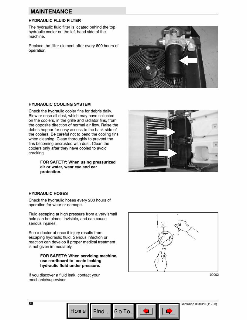
MAINTENANCE
Centurion 331020 (11--03)88
HYDRAULIC FLUID FILTER
The hydraulic fluid filter is located behind the tophydraulic cooler on the left hand side of themachine.
Replace the filter element after every 800 hours ofoperation.
HYDRAULIC COOLING SYSTEM
Check the hydraulic cooler fins for debris daily.Blow or rinse all dust, which may have collectedon the coolers, in the grille and radiator fins, fromthe opposite direction of normal air flow. Raise thedebris hopper for easy access to the back side ofthe coolers. Be careful not to bend the cooling finswhen cleaning. Clean thoroughly to prevent thefins becoming encrusted with dust. Clean thecoolers only after they have cooled to avoidcracking.
FOR SAFETY: When using pressurizedair or water, wear eye and earprotection.
HYDRAULIC HOSES
Check the hydraulic hoses every 200 hours ofoperation for wear or damage.
Fluid escaping at high pressure from a very smallhole can be almost invisible, and can causeserious injuries.
See a doctor at once if injury results fromescaping hydraulic fluid. Serious infection orreaction can develop if proper medical treatmentis not given immediately.
FOR SAFETY: When servicing machine,use cardboard to locate leakinghydraulic fluid under pressure.
If you discover a fluid leak, contact yourmechanic/supervisor.
00002
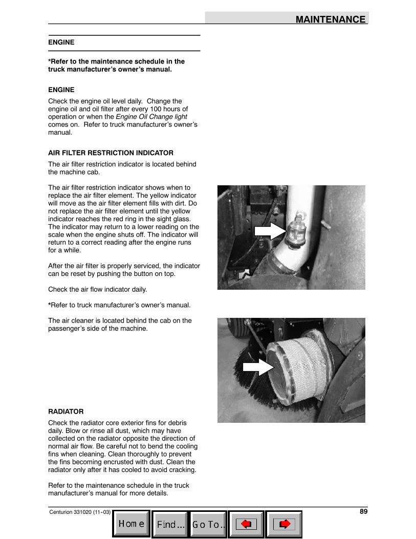
MAINTENANCE
89Centurion 331020 (11--03)
ENGINE
*Refer to the maintenance schedule in thetruck manufacturer’s owner’s manual.
ENGINE
Check the engine oil level daily. Change theengine oil and oil filter after every 100 hours ofoperation or when the Engine Oil Change lightcomes on. Refer to truck manufacturer’s owner’smanual.
AIR FILTER RESTRICTION INDICATOR
The air filter restriction indicator is located behindthe machine cab.
The air filter restriction indicator shows when toreplace the air filter element. The yellow indicatorwill move as the air filter element fills with dirt. Donot replace the air filter element until the yellowindicator reaches the red ring in the sight glass.The indicator may return to a lower reading on thescale when the engine shuts off. The indicator willreturn to a correct reading after the engine runsfor a while.
After the air filter is properly serviced, the indicatorcan be reset by pushing the button on top.
Check the air flow indicator daily.
*Refer to truck manufacturer’s owner’s manual.
The air cleaner is located behind the cab on thepassenger’s side of the machine.
RADIATOR
Check the radiator core exterior fins for debrisdaily. Blow or rinse all dust, which may havecollected on the radiator opposite the direction ofnormal air flow. Be careful not to bend the coolingfins when cleaning. Clean thoroughly to preventthe fins becoming encrusted with dust. Clean theradiator only after it has cooled to avoid cracking.
Refer to the maintenance schedule in the truckmanufacturer’s manual for more details.
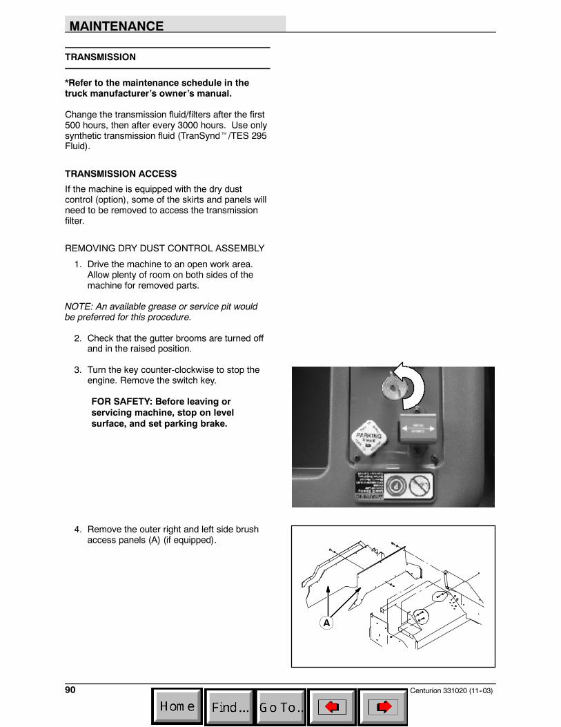
MAINTENANCE
Centurion 331020 (11--03)90
TRANSMISSION
*Refer to the maintenance schedule in thetruck manufacturer’s owner’s manual.
Change the transmission fluid/filters after the first500 hours, then after every 3000 hours. Use onlysynthetic transmission fluid (TranSyndt/TES 295Fluid).
TRANSMISSION ACCESS
If the machine is equipped with the dry dustcontrol (option), some of the skirts and panels willneed to be removed to access the transmissionfilter.
REMOVING DRY DUST CONTROL ASSEMBLY
1. Drive the machine to an open work area.Allow plenty of room on both sides of themachine for removed parts.
NOTE: An available grease or service pit wouldbe preferred for this procedure.
2. Check that the gutter brooms are turned offand in the raised position.
3. Turn the key counter-clockwise to stop theengine. Remove the switch key.
FOR SAFETY: Before leaving orservicing machine, stop on levelsurface, and set parking brake.
4. Remove the outer right and left side brushaccess panels (A) (if equipped).
A
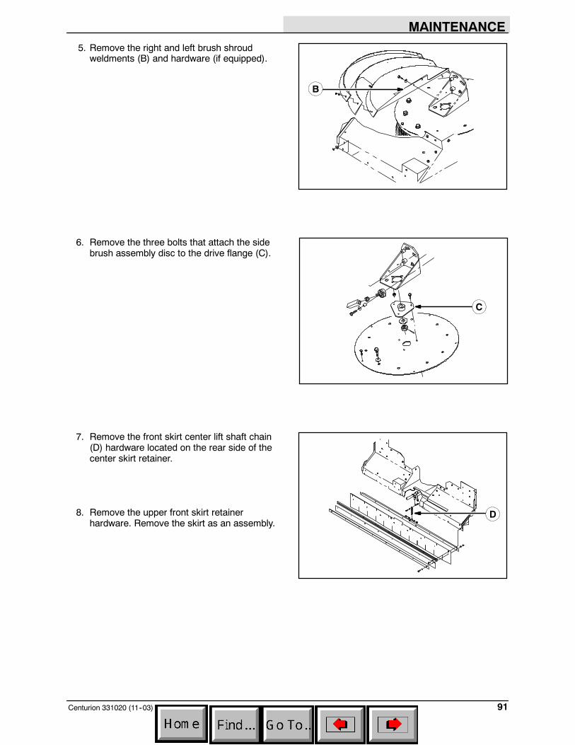
MAINTENANCE
91Centurion 331020 (11--03)
5. Remove the right and left brush shroudweldments (B) and hardware (if equipped).
6. Remove the three bolts that attach the sidebrush assembly disc to the drive flange (C).
7. Remove the front skirt center lift shaft chain(D) hardware located on the rear side of thecenter skirt retainer.
8. Remove the upper front skirt retainerhardware. Remove the skirt as an assembly.
B
C
D
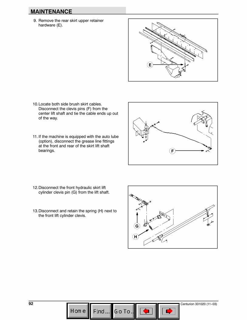
MAINTENANCE
Centurion 331020 (11--03)92
9. Remove the rear skirt upper retainerhardware (E).
10.Locate both side brush skirt cables.Disconnect the clevis pins (F) from thecenter lift shaft and tie the cable ends up outof the way.
11. If the machine is equipped with the auto lube(option), disconnect the grease line fittingsat the front and rear of the skirt lift shaftbearings.
12.Disconnect the front hydraulic skirt liftcylinder clevis pin (G) from the lift shaft.
13.Disconnect and retain the spring (H) next tothe front lift cylinder clevis.
E
F
G
H
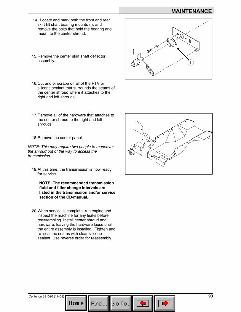
MAINTENANCE
93Centurion 331020 (11--03)
14. Locate and mark both the front and rearskirt lift shaft bearing mounts (I), andremove the bolts that hold the bearing andmount to the center shroud.
15.Remove the center skirt shaft deflectorassembly.
16.Cut and or scrape off all of the RTV orsilicone sealant that surrounds the seams ofthe center shroud where it attaches to theright and left shrouds.
17.Remove all of the hardware that attaches tothe center shroud to the right and leftshrouds.
18.Remove the center panel.
NOTE: This may require two people to maneuverthe shroud out of the way to access thetransmission.
19.At this time, the transmission is now readyfor service.
NOTE: The recommended transmissionfluid and filter change intervals arelisted in the transmission and/or servicesection of the CD/manual.
20.When service is complete, run engine andinspect the machine for any leaks beforereassembling. Install center shroud andhardware, leaving the hardware loose untilthe entire assembly is installed. Tighten andre--seal the seams with clear siliconesealant. Use reverse order for reassembly.
I
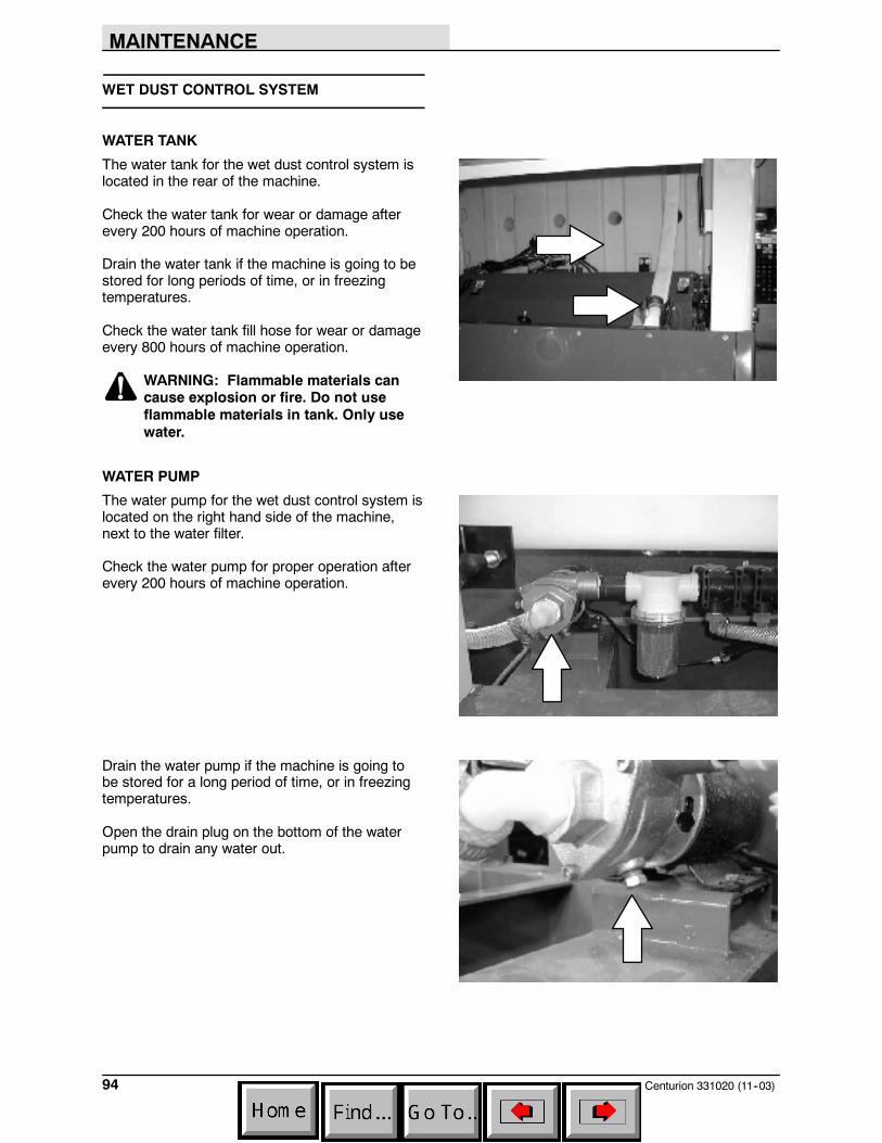
MAINTENANCE
Centurion 331020 (11--03)94
WET DUST CONTROL SYSTEM
WATER TANK
The water tank for the wet dust control system islocated in the rear of the machine.
Check the water tank for wear or damage afterevery 200 hours of machine operation.
Drain the water tank if the machine is going to bestored for long periods of time, or in freezingtemperatures.
Check the water tank fill hose for wear or damageevery 800 hours of machine operation.
WARNING: Flammable materials cancause explosion or fire. Do not useflammable materials in tank. Only usewater.
WATER PUMP
The water pump for the wet dust control system islocated on the right hand side of the machine,next to the water filter.
Check the water pump for proper operation afterevery 200 hours of machine operation.
Drain the water pump if the machine is going tobe stored for a long period of time, or in freezingtemperatures.
Open the drain plug on the bottom of the waterpump to drain any water out.
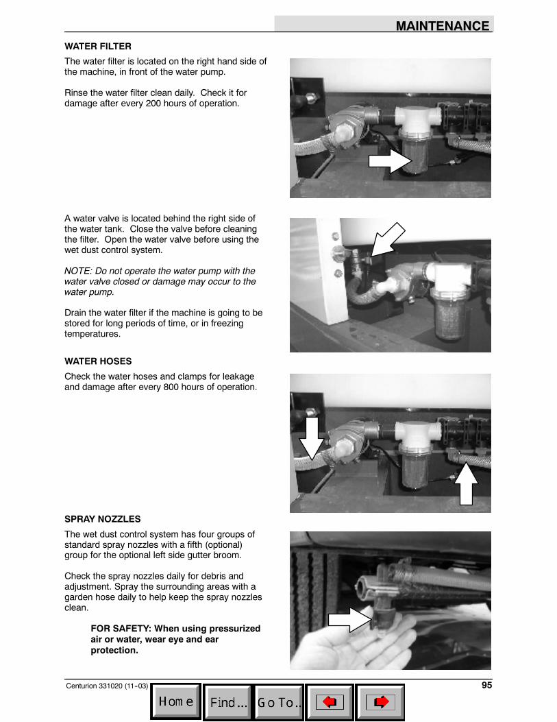
MAINTENANCE
95Centurion 331020 (11--03)
WATER FILTER
The water filter is located on the right hand side ofthe machine, in front of the water pump.
Rinse the water filter clean daily. Check it fordamage after every 200 hours of operation.
A water valve is located behind the right side ofthe water tank. Close the valve before cleaningthe filter. Open the water valve before using thewet dust control system.
NOTE: Do not operate the water pump with thewater valve closed or damage may occur to thewater pump.
Drain the water filter if the machine is going to bestored for long periods of time, or in freezingtemperatures.
WATER HOSES
Check the water hoses and clamps for leakageand damage after every 800 hours of operation.
SPRAY NOZZLES
The wet dust control system has four groups ofstandard spray nozzles with a fifth (optional)group for the optional left side gutter broom.
Check the spray nozzles daily for debris andadjustment. Spray the surrounding areas with agarden hose daily to help keep the spray nozzlesclean.
FOR SAFETY: When using pressurizedair or water, wear eye and earprotection.
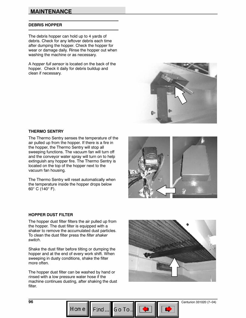
MAINTENANCE
Centurion 331020 (7--04)96
DEBRIS HOPPER
The debris hopper can hold up to 4 yards ofdebris. Check for any leftover debris each timeafter dumping the hopper. Check the hopper forwear or damage daily. Rinse the hopper out whenwashing the machine or as necessary.
A hopper full sensor is located on the back of thehopper. Check it daily for debris buildup andclean if necessary.
THERMO SENTRY
The Thermo Sentry senses the temperature of theair pulled up from the hopper. If there is a fire inthe hopper, the Thermo Sentry will stop allsweeping functions. The vacuum fan will turn offand the conveyor water spray will turn on to helpextinguish any hopper fire. The Thermo Sentry islocated on the top of the hopper next to thevacuum fan housing.
The Thermo Sentry will reset automatically whenthe temperature inside the hopper drops below60° C (140° F).
HOPPER DUST FILTER
The hopper dust filter filters the air pulled up fromthe hopper. The dust filter is equipped with ashaker to remove the accumulated dust particles.To clean the dust filter press the filter shakerswitch.
Shake the dust filter before tilting or dumping thehopper and at the end of every work shift. Whensweeping in dusty conditions, shake the filtermore often.
The hopper dust filter can be washed by hand orrinsed with a low pressure water hose if themachine continues dusting, after shaking the dustfilter.
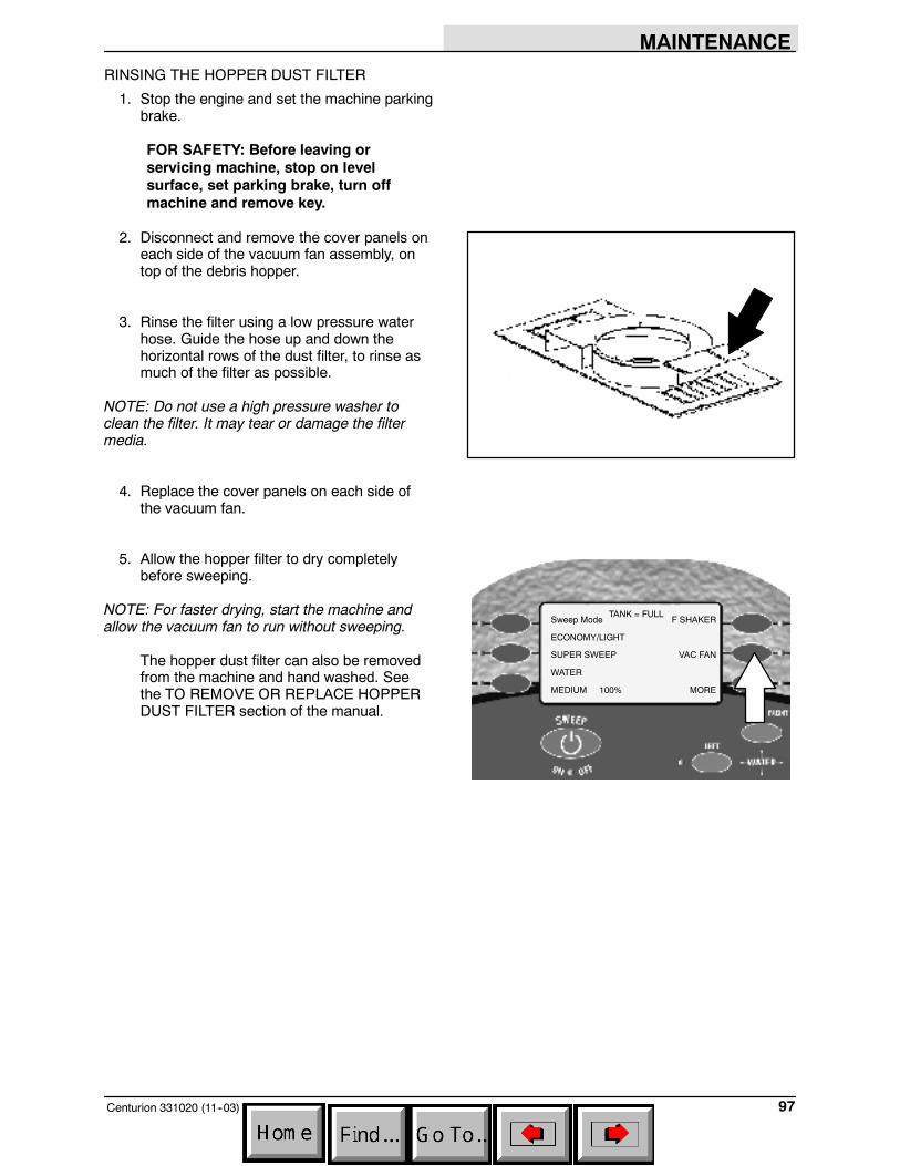
MAINTENANCE
97Centurion 331020 (11--03)
RINSING THE HOPPER DUST FILTER
1. Stop the engine and set the machine parkingbrake.
FOR SAFETY: Before leaving orservicing machine, stop on levelsurface, set parking brake, turn offmachine and remove key.
2. Disconnect and remove the cover panels oneach side of the vacuum fan assembly, ontop of the debris hopper.
3. Rinse the filter using a low pressure waterhose. Guide the hose up and down thehorizontal rows of the dust filter, to rinse asmuch of the filter as possible.
NOTE: Do not use a high pressure washer toclean the filter. It may tear or damage the filtermedia.
4. Replace the cover panels on each side ofthe vacuum fan.
5. Allow the hopper filter to dry completelybefore sweeping.
NOTE: For faster drying, start the machine andallow the vacuum fan to run without sweeping.
The hopper dust filter can also be removedfrom the machine and hand washed. Seethe TO REMOVE OR REPLACE HOPPERDUST FILTER section of the manual.
Sweep Mode
ECONOMY/LIGHT
SUPER SWEEP
WATER
MEDIUM 100%
F SHAKER
VAC FAN
MORE
TANK = FULL
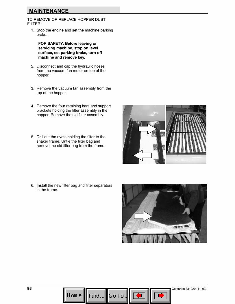
MAINTENANCE
Centurion 331020 (11--03)98
TO REMOVE OR REPLACE HOPPER DUSTFILTER
1. Stop the engine and set the machine parkingbrake.
FOR SAFETY: Before leaving orservicing machine, stop on levelsurface, set parking brake, turn offmachine and remove key.
2. Disconnect and cap the hydraulic hosesfrom the vacuum fan motor on top of thehopper.
3. Remove the vacuum fan assembly from thetop of the hopper.
4. Remove the four retaining bars and supportbrackets holding the filter assembly in thehopper. Remove the old filter assembly.
5. Drill out the rivets holding the filter to theshaker frame. Untie the filter bag andremove the old filter bag from the frame.
6. Install the new filter bag and filter separatorsin the frame.
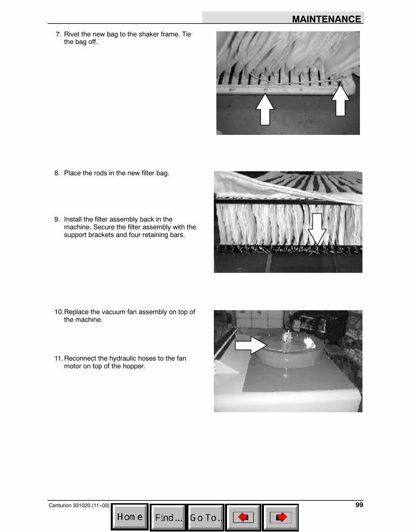
MAINTENANCE
99Centurion 331020 (11--03)
7. Rivet the new bag to the shaker frame. Tiethe bag off.
8. Place the rods in the new filter bag.
9. Install the filter assembly back in themachine. Secure the filter assembly with thesupport brackets and four retaining bars.
10.Replace the vacuum fan assembly on top ofthe machine.
11.Reconnect the hydraulic hoses to the fanmotor on top of the hopper.
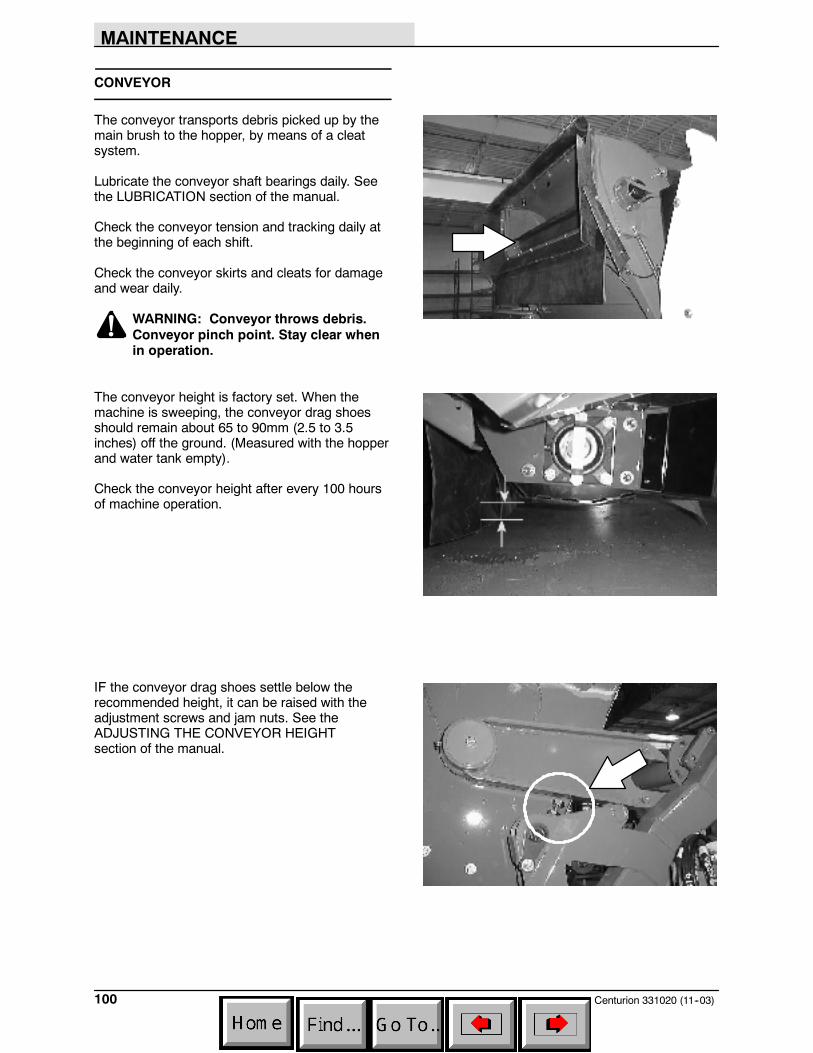
MAINTENANCE
Centurion 331020 (11--03)100
CONVEYOR
The conveyor transports debris picked up by themain brush to the hopper, by means of a cleatsystem.
Lubricate the conveyor shaft bearings daily. Seethe LUBRICATION section of the manual.
Check the conveyor tension and tracking daily atthe beginning of each shift.
Check the conveyor skirts and cleats for damageand wear daily.
WARNING: Conveyor throws debris.Conveyor pinch point. Stay clear whenin operation.
The conveyor height is factory set. When themachine is sweeping, the conveyor drag shoesshould remain about 65 to 90mm (2.5 to 3.5inches) off the ground. (Measured with the hopperand water tank empty).
Check the conveyor height after every 100 hoursof machine operation.
IF the conveyor drag shoes settle below therecommended height, it can be raised with theadjustment screws and jam nuts. See theADJUSTING THE CONVEYOR HEIGHTsection of the manual.
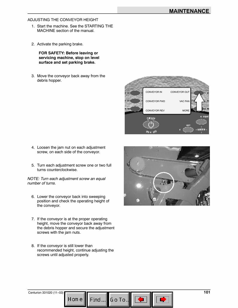
MAINTENANCE
101Centurion 331020 (11--03)
ADJUSTING THE CONVEYOR HEIGHT
1. Start the machine. See the STARTING THEMACHINE section of the manual.
2. Activate the parking brake.
FOR SAFETY: Before leaving orservicing machine, stop on levelsurface and set parking brake.
3. Move the conveyor back away from thedebris hopper.
4. Loosen the jam nut on each adjustmentscrew, on each side of the conveyor.
5. Turn each adjustment screw one or two fullturns counterclockwise.
NOTE: Turn each adjustment screw an equalnumber of turns.
6. Lower the conveyor back into sweepingposition and check the operating height ofthe conveyor.
7. If the conveyor is at the proper operatingheight, move the conveyor back away fromthe debris hopper and secure the adjustmentscrews with the jam nuts.
8. If the conveyor is still lower thanrecommended height, continue adjusting thescrews until adjusted properly.
CONVEYOR IN
CONVEYOR FWD
CONVEYOR REV
CONVEYOR OUT
VAC FAN
MORE
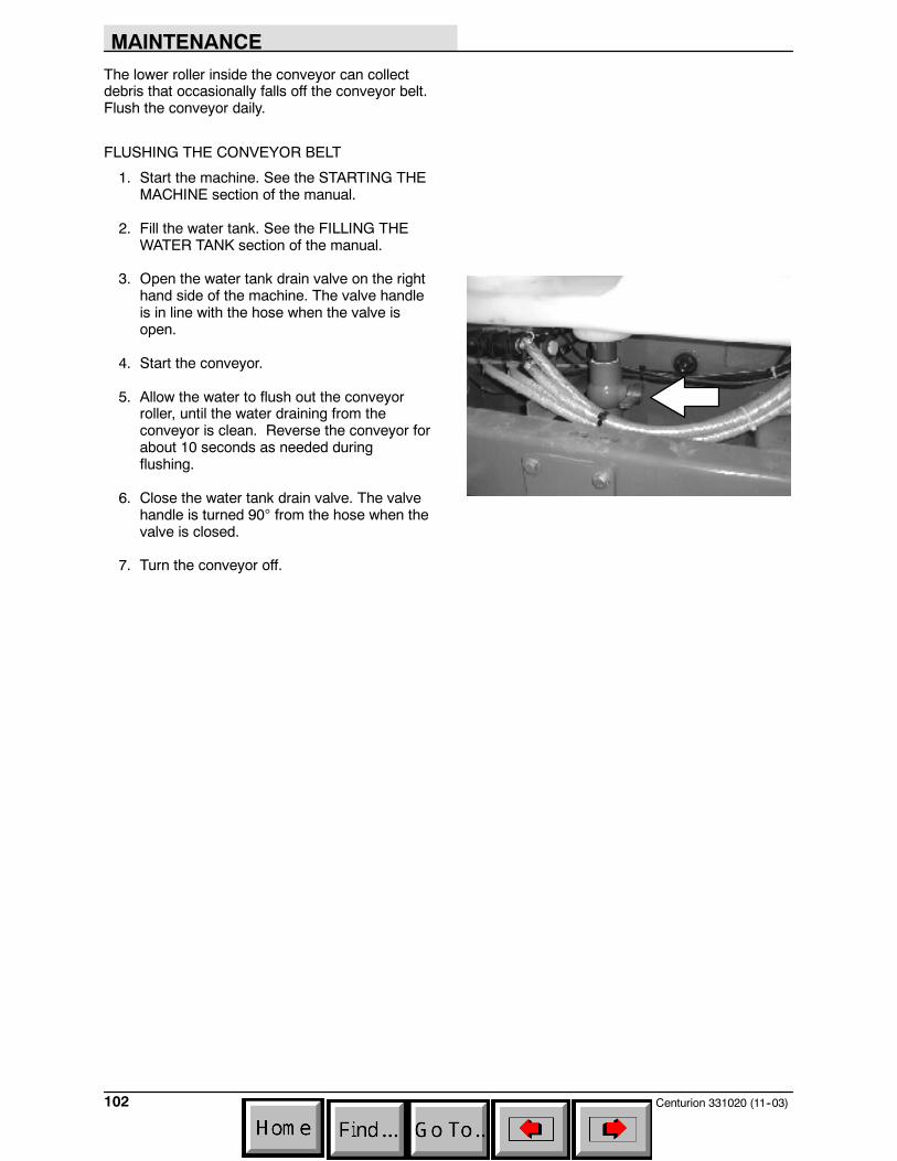
MAINTENANCE
Centurion 331020 (11--03)102
The lower roller inside the conveyor can collectdebris that occasionally falls off the conveyor belt.Flush the conveyor daily.
FLUSHING THE CONVEYOR BELT
1. Start the machine. See the STARTING THEMACHINE section of the manual.
2. Fill the water tank. See the FILLING THEWATER TANK section of the manual.
3. Open the water tank drain valve on the righthand side of the machine. The valve handleis in line with the hose when the valve isopen.
4. Start the conveyor.
5. Allow the water to flush out the conveyorroller, until the water draining from theconveyor is clean. Reverse the conveyor forabout 10 seconds as needed duringflushing.
6. Close the water tank drain valve. The valvehandle is turned 90° from the hose when thevalve is closed.
7. Turn the conveyor off.
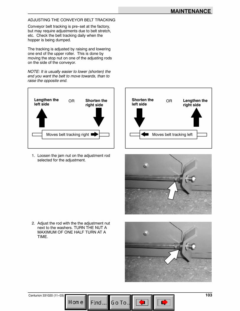
MAINTENANCE
103Centurion 331020 (11--03)
ADJUSTING THE CONVEYOR BELT TRACKING
Conveyor belt tracking is pre--set at the factory,but may require adjustments due to belt stretch,etc. Check the belt tracking daily when thehopper is being dumped.
The tracking is adjusted by raising and loweringone end of the upper roller. This is done bymoving the stop nut on one of the adjusting rodson the side of the conveyor.
NOTE: It is usually easier to lower (shorten) theend you want the belt to move towards, than toraise the opposite end.
Moves belt tracking left
Shorten theleft side
Lengthen theright side
OR
Moves belt tracking right
Lengthen theleft side
Shorten theright side
OR
1. Loosen the jam nut on the adjustment rodselected for the adjustment.
2. Adjust the rod with the the adjustment nutnext to the washers. TURN THE NUT AMAXIMUM OF ONE HALF TURN AT ATIME.
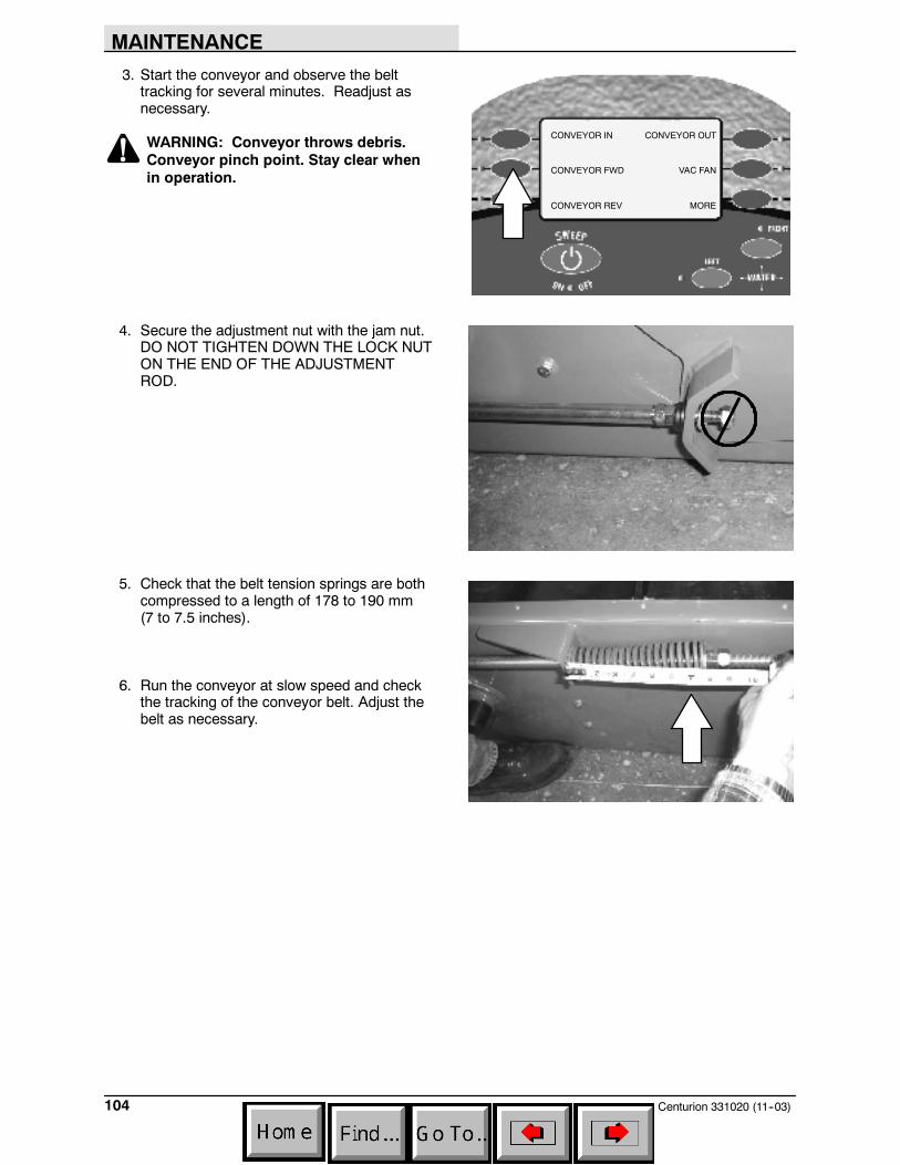
MAINTENANCE
Centurion 331020 (11--03)104
3. Start the conveyor and observe the belttracking for several minutes. Readjust asnecessary.
WARNING: Conveyor throws debris.Conveyor pinch point. Stay clear whenin operation.
4. Secure the adjustment nut with the jam nut.DO NOT TIGHTEN DOWN THE LOCK NUTON THE END OF THE ADJUSTMENTROD.
5. Check that the belt tension springs are bothcompressed to a length of 178 to 190 mm(7 to 7.5 inches).
6. Run the conveyor at slow speed and checkthe tracking of the conveyor belt. Adjust thebelt as necessary.
CONVEYOR IN
CONVEYOR FWD
CONVEYOR REV
CONVEYOR OUT
VAC FAN
MORE
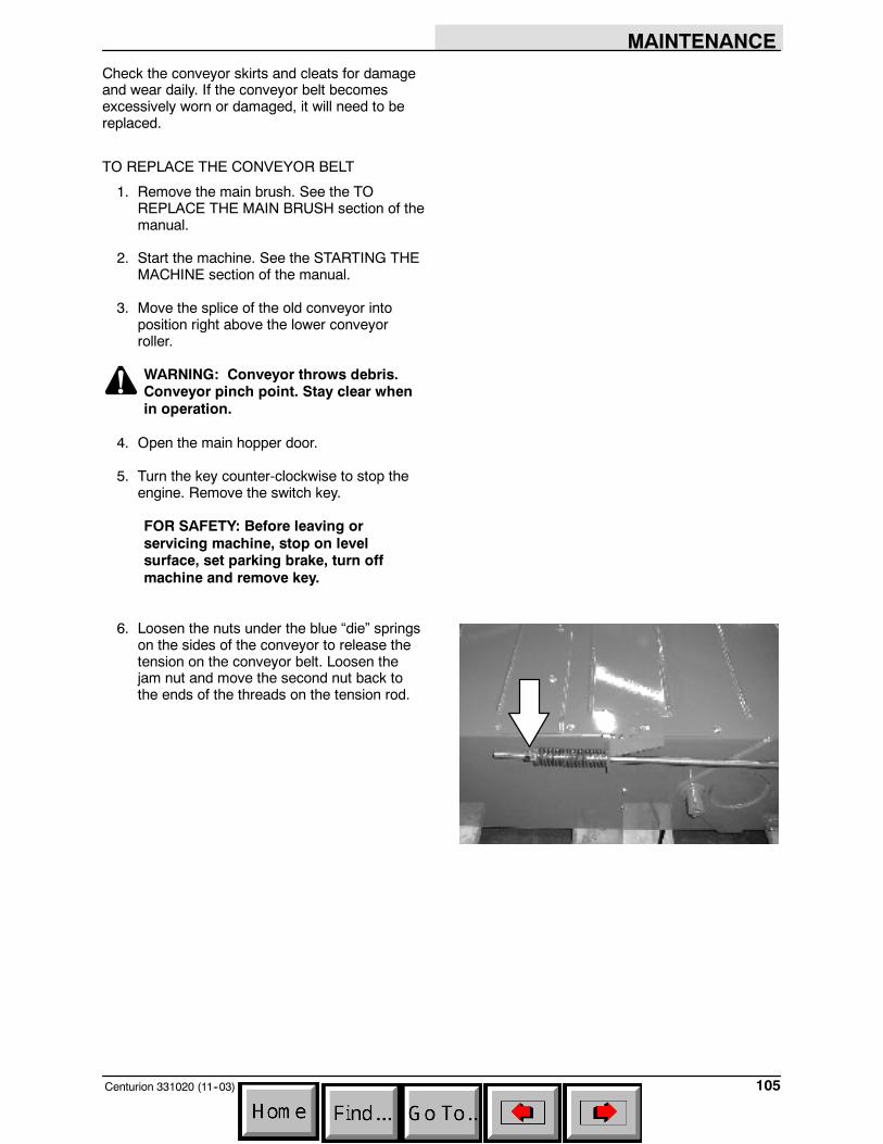
MAINTENANCE
105Centurion 331020 (11--03)
Check the conveyor skirts and cleats for damageand wear daily. If the conveyor belt becomesexcessively worn or damaged, it will need to bereplaced.
TO REPLACE THE CONVEYOR BELT
1. Remove the main brush. See the TOREPLACE THE MAIN BRUSH section of themanual.
2. Start the machine. See the STARTING THEMACHINE section of the manual.
3. Move the splice of the old conveyor intoposition right above the lower conveyorroller.
WARNING: Conveyor throws debris.Conveyor pinch point. Stay clear whenin operation.
4. Open the main hopper door.
5. Turn the key counter-clockwise to stop theengine. Remove the switch key.
FOR SAFETY: Before leaving orservicing machine, stop on levelsurface, set parking brake, turn offmachine and remove key.
6. Loosen the nuts under the blue “die” springson the sides of the conveyor to release thetension on the conveyor belt. Loosen thejam nut and move the second nut back tothe ends of the threads on the tension rod.
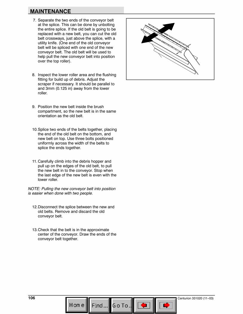
MAINTENANCE
Centurion 331020 (11--03)106
7. Separate the two ends of the conveyor beltat the splice. This can be done by unboltingthe entire splice. If the old belt is going to bereplaced with a new belt, you can cut the oldbelt crossways, just above the splice, with autility knife. (One end of the old conveyorbelt will be spliced with one end of the newconveyor belt. The old belt will be used tohelp pull the new conveyor belt into positionover the top roller).
8. Inspect the lower roller area and the flushingfitting for build up of debris. Adjust thescraper if necessary. It should be parallel toand 3mm (0.125 in) away from the lowerroller.
9. Position the new belt inside the brushcompartment, so the new belt is in the sameorientation as the old belt.
10.Splice two ends of the belts together, placingthe end of the old belt on the bottom, andnew belt on top. Use three bolts positioneduniformly across the width of the belts tosplice the ends together.
11.Carefully climb into the debris hopper andpull up on the edges of the old belt, to pullthe new belt in to the conveyor. Stop whenthe last edge of the new belt is even with thelower roller.
NOTE: Pulling the new conveyor belt into positionis easier when done with two people.
12.Disconnect the splice between the new andold belts. Remove and discard the oldconveyor belt.
13.Check that the belt is in the approximatecenter of the conveyor. Draw the ends of theconveyor belt together.
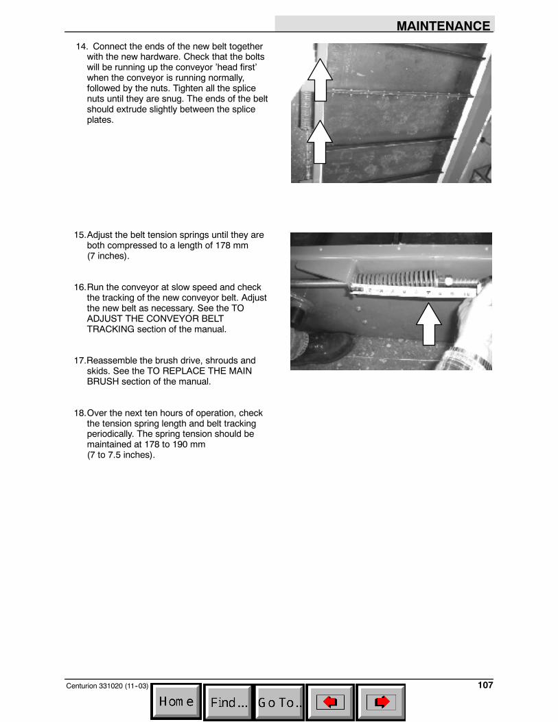
MAINTENANCE
107Centurion 331020 (11--03)
14. Connect the ends of the new belt togetherwith the new hardware. Check that the boltswill be running up the conveyor ’head first’when the conveyor is running normally,followed by the nuts. Tighten all the splicenuts until they are snug. The ends of the beltshould extrude slightly between the spliceplates.
15.Adjust the belt tension springs until they areboth compressed to a length of 178 mm(7 inches).
16.Run the conveyor at slow speed and checkthe tracking of the new conveyor belt. Adjustthe new belt as necessary. See the TOADJUST THE CONVEYOR BELTTRACKING section of the manual.
17.Reassemble the brush drive, shrouds andskids. See the TO REPLACE THE MAINBRUSH section of the manual.
18.Over the next ten hours of operation, checkthe tension spring length and belt trackingperiodically. The spring tension should bemaintained at 178 to 190 mm(7 to 7.5 inches).
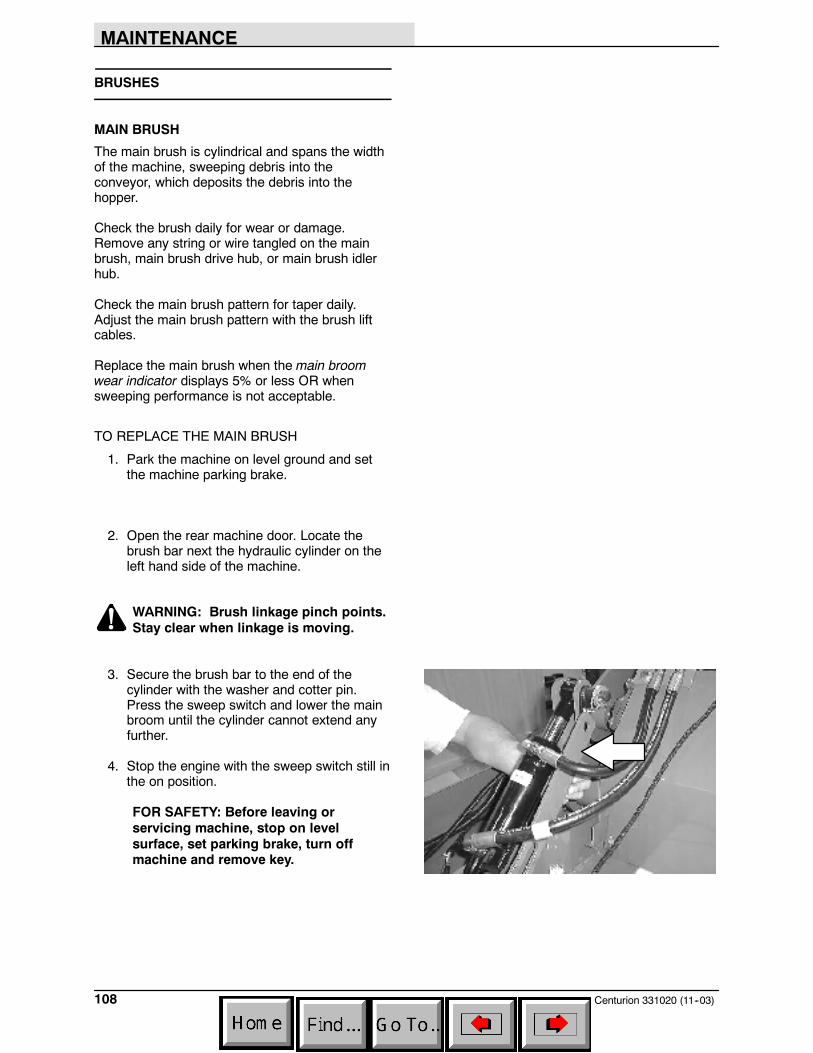
MAINTENANCE
Centurion 331020 (11--03)108
BRUSHES
MAIN BRUSH
The main brush is cylindrical and spans the widthof the machine, sweeping debris into theconveyor, which deposits the debris into thehopper.
Check the brush daily for wear or damage.Remove any string or wire tangled on the mainbrush, main brush drive hub, or main brush idlerhub.
Check the main brush pattern for taper daily.Adjust the main brush pattern with the brush liftcables.
Replace the main brush when the main broomwear indicator displays 5% or less OR whensweeping performance is not acceptable.
TO REPLACE THE MAIN BRUSH
1. Park the machine on level ground and setthe machine parking brake.
2. Open the rear machine door. Locate thebrush bar next the hydraulic cylinder on theleft hand side of the machine.
WARNING: Brush linkage pinch points.Stay clear when linkage is moving.
3. Secure the brush bar to the end of thecylinder with the washer and cotter pin.Press the sweep switch and lower the mainbroom until the cylinder cannot extend anyfurther.
4. Stop the engine with the sweep switch still inthe on position.
FOR SAFETY: Before leaving orservicing machine, stop on levelsurface, set parking brake, turn offmachine and remove key.

MAINTENANCE
109Centurion 331020 (7--04)
5. Remove the cover panels from the right sideof the machine. Set the nuts and washersaside.
6. Disconnect and remove the rear section ofthe idler arm from the main brush and the liftarm.
7. Mark the joint of the drag shoe armassembly and remove the drag shoe armassembly from the mounting arm.
NOTE: Note the location of the mountingfasteners before disassembly. The drag shoesshould be reassembled in the same position onmarked locations after the new broom has beeninstalled.
8. Remove the old brush from the machine.
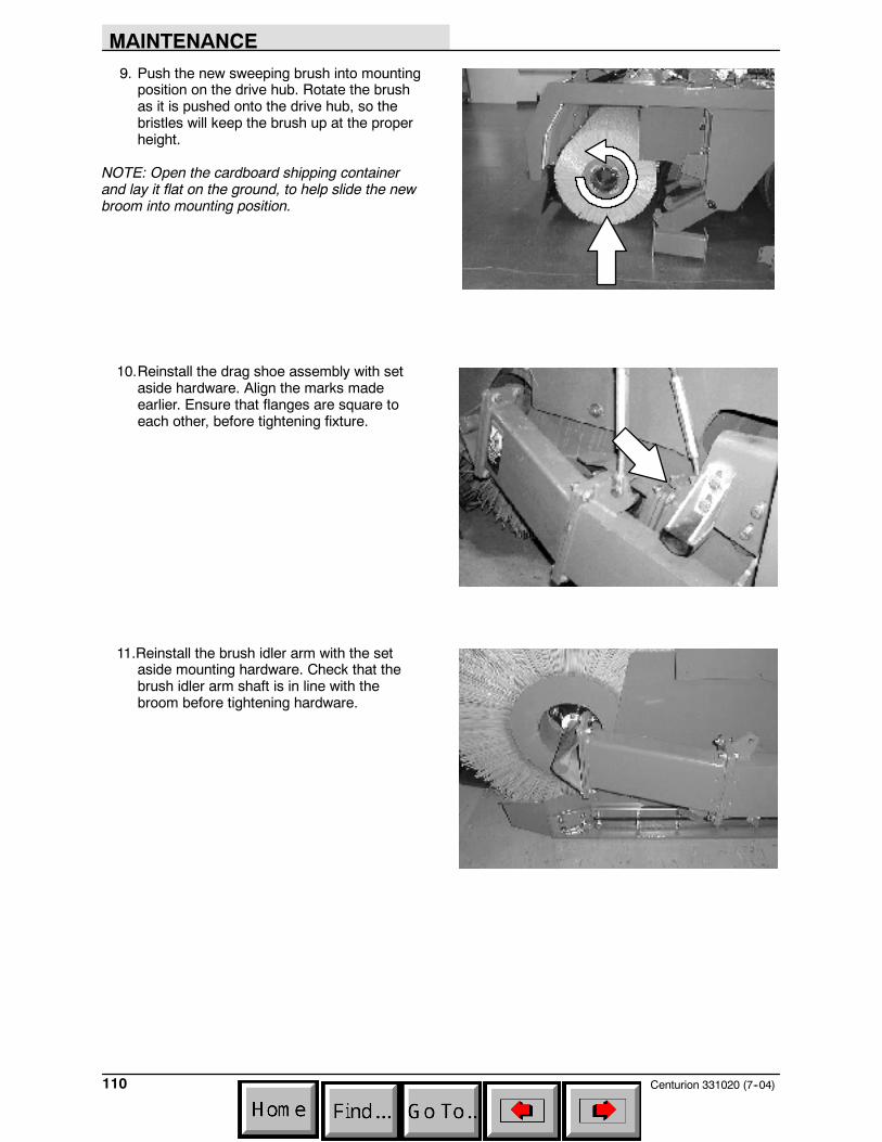
MAINTENANCE
Centurion 331020 (7--04)110
9. Push the new sweeping brush into mountingposition on the drive hub. Rotate the brushas it is pushed onto the drive hub, so thebristles will keep the brush up at the properheight.
NOTE: Open the cardboard shipping containerand lay it flat on the ground, to help slide the newbroom into mounting position.
10.Reinstall the drag shoe assembly with setaside hardware. Align the marks madeearlier. Ensure that flanges are square toeach other, before tightening fixture.
11.Reinstall the brush idler arm with the setaside mounting hardware. Check that thebrush idler arm shaft is in line with thebroom before tightening hardware.
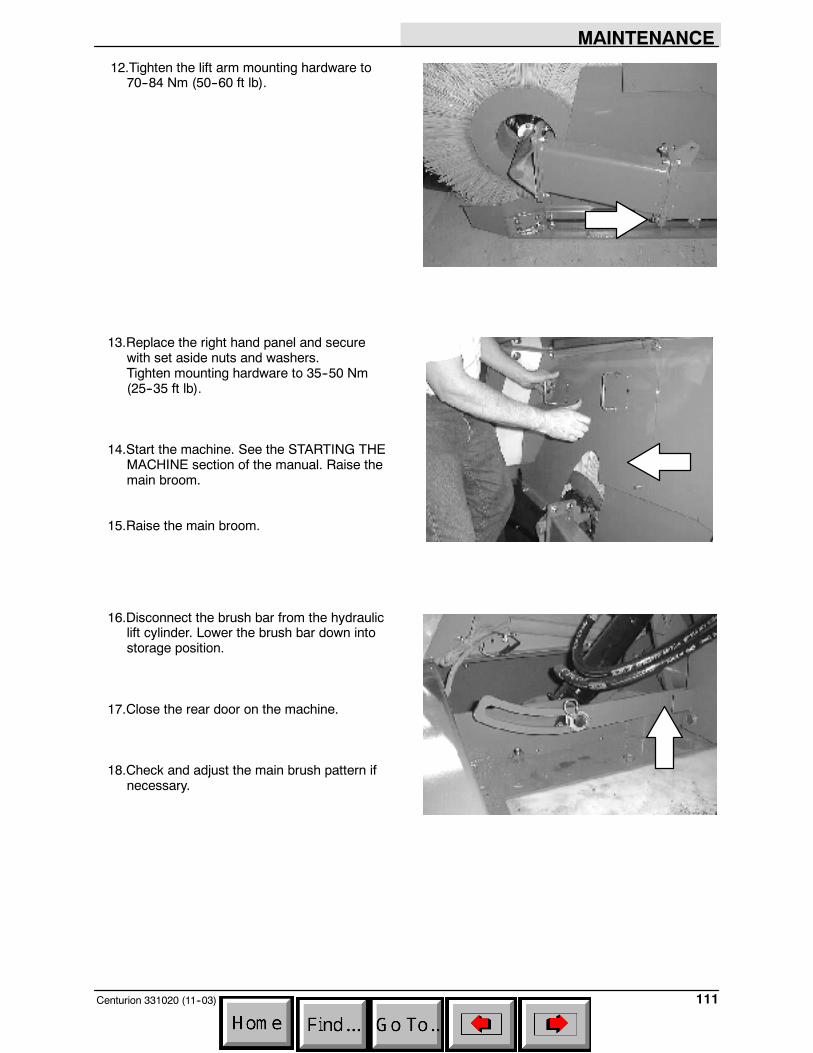
MAINTENANCE
111Centurion 331020 (11--03)
12.Tighten the lift arm mounting hardware to70--84 Nm (50--60 ft lb).
13.Replace the right hand panel and securewith set aside nuts and washers.Tighten mounting hardware to 35--50 Nm(25--35 ft lb).
14.Start the machine. See the STARTING THEMACHINE section of the manual. Raise themain broom.
15.Raise the main broom.
16.Disconnect the brush bar from the hydrauliclift cylinder. Lower the brush bar down intostorage position.
17.Close the rear door on the machine.
18.Check and adjust the main brush pattern ifnecessary.
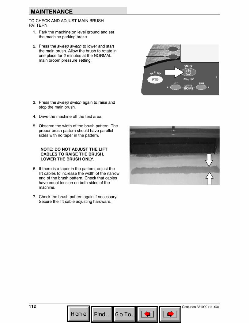
MAINTENANCE
Centurion 331020 (11--03)112
TO CHECK AND ADJUST MAIN BRUSHPATTERN
1. Park the machine on level ground and setthe machine parking brake.
2. Press the sweep switch to lower and startthe main brush. Allow the brush to rotate inone place for 2 minutes at the NORMALmain broom pressure setting.
3. Press the sweep switch again to raise andstop the main brush.
4. Drive the machine off the test area.
5. Observe the width of the brush pattern. Theproper brush pattern should have parallelsides with no taper in the pattern.
NOTE: DO NOT ADJUST THE LIFTCABLES TO RAISE THE BRUSH.LOWER THE BRUSH ONLY.
6. If there is a taper in the pattern, adjust thelift cables to increase the width of the narrowend of the brush pattern. Check that cableshave equal tension on both sides of themachine.
7. Check the brush pattern again if necessary.Secure the lift cable adjusting hardware.
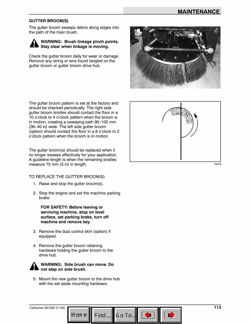
MAINTENANCE
113Centurion 331020 (7--04)
GUTTER BROOM(S)
The gutter broom sweeps debris along edges intothe path of the main brush.
WARNING: Brush linkage pinch points.Stay clear when linkage is moving.
Check the gutter broom daily for wear or damage.Remove any string or wire found tangled on thegutter broom or gutter broom drive hub.
The gutter broom pattern is set at the factory andshould be checked periodically. The right sidegutter broom bristles should contact the floor in a10 o’clock to 4 o’clock pattern when the broom isin motion, creating a sweeping path 90--100 mm(36--40 in) wide. The left side gutter broom(option) should contact the floor in a 8 o’clock to 2o’clock pattern when the broom is in motion.
The gutter broom(s) should be replaced when itno longer sweeps effectively for your application.A guideline length is when the remaining bristlesmeasure 75 mm (3 in) in length.
TO REPLACE THE GUTTER BROOM(S)
1. Raise and stop the gutter broom(s).
2. Stop the engine and set the machine parkingbrake.
FOR SAFETY: Before leaving orservicing machine, stop on levelsurface, set parking brake, turn offmachine and remove key.
3. Remove the dust control skirt (option) ifequipped.
4. Remove the gutter broom retaininghardware holding the gutter broom to thedrive hub.
WARNING: Side brush can move. Donot step on side brush.
5. Mount the new gutter broom to the drive hubwith the set aside mounting hardware.
03376
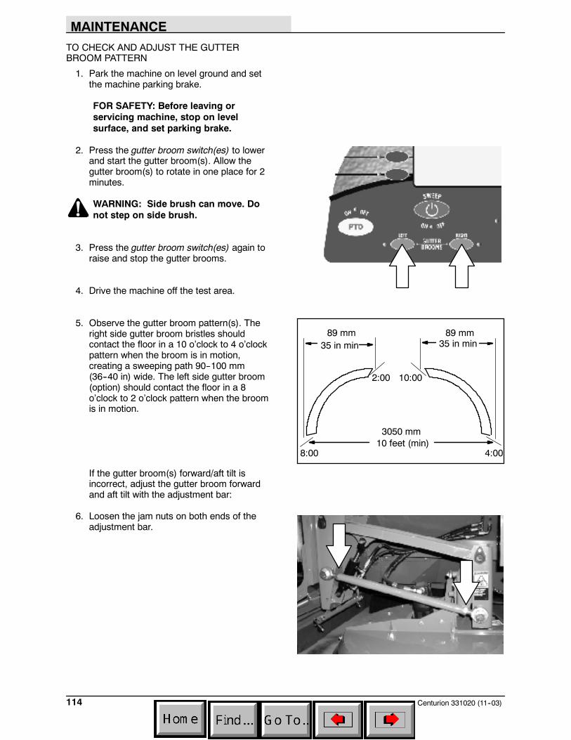
MAINTENANCE
Centurion 331020 (11--03)114
TO CHECK AND ADJUST THE GUTTERBROOM PATTERN
1. Park the machine on level ground and setthe machine parking brake.
FOR SAFETY: Before leaving orservicing machine, stop on levelsurface, and set parking brake.
2. Press the gutter broom switch(es) to lowerand start the gutter broom(s). Allow thegutter broom(s) to rotate in one place for 2minutes.
WARNING: Side brush can move. Donot step on side brush.
3. Press the gutter broom switch(es) again toraise and stop the gutter brooms.
4. Drive the machine off the test area.
5. Observe the gutter broom pattern(s). Theright side gutter broom bristles shouldcontact the floor in a 10 o’clock to 4 o’clockpattern when the broom is in motion,creating a sweeping path 90--100 mm(36--40 in) wide. The left side gutter broom(option) should contact the floor in a 8o’clock to 2 o’clock pattern when the broomis in motion.
If the gutter broom(s) forward/aft tilt isincorrect, adjust the gutter broom forwardand aft tilt with the adjustment bar:
6. Loosen the jam nuts on both ends of theadjustment bar.
35 in min 35 in min
10 feet (min)
2:00 10:00
8:00 4:00
89 mm 89 mm
3050 mm

MAINTENANCE
115Centurion 331020 (11--03)
7. Rotate the adjustment bar clockwise orcounterclockwise to decrease or increasethe forward/aft tilt angle.
8. Tighten the jam nuts on both ends of theadjustment bar.
If the gutter broom(s) side to sideadjustment is incorrect, adjust the side toside tilt with the square adjustment bar:
9. Loosen the motor mount securing screw andthe jam nut on the end of the squareadjustment bar.
10.Rotate the square adjustment bar clockwiseor counterclockwise to decrease or increasethe side to side angle of tilt.
11.Tighten the jam nut on the end of the squareadjustment bar and the motor mountsecuring screw.
12.Check the gutter broom pattern again ifnecessary. Check that all of the adjustmentbar jam nuts are secure.
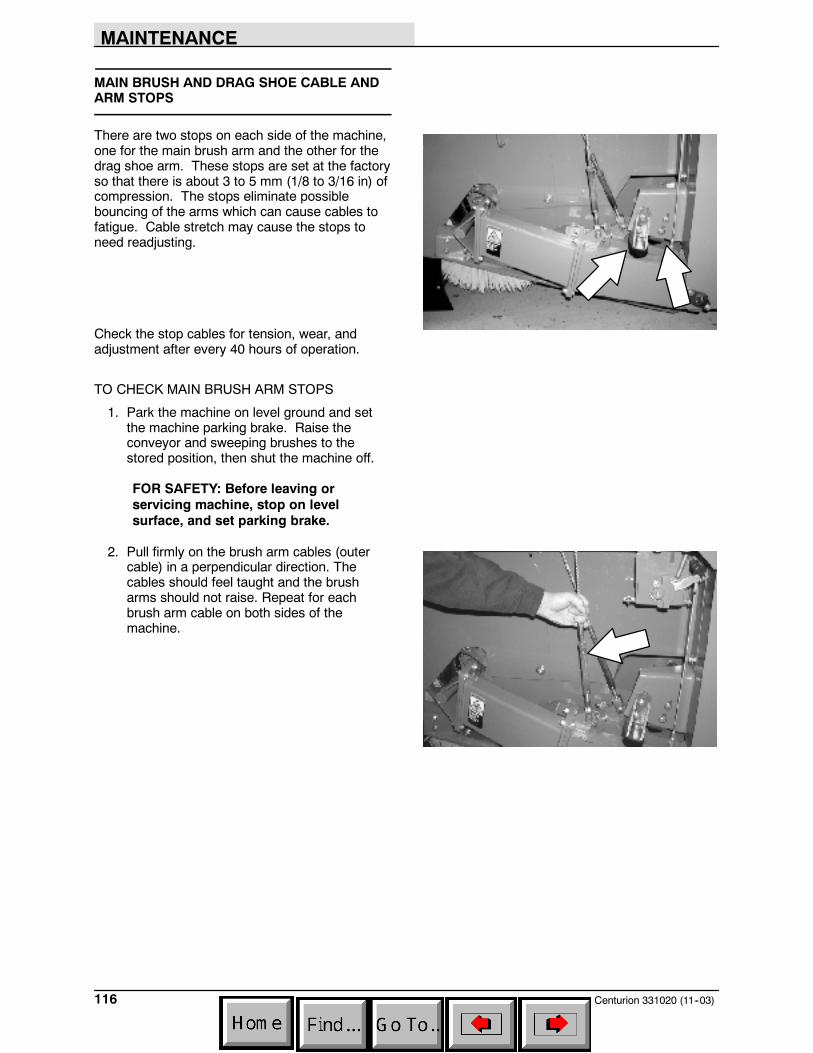
MAINTENANCE
Centurion 331020 (11--03)116
MAIN BRUSH AND DRAG SHOE CABLE ANDARM STOPS
There are two stops on each side of the machine,one for the main brush arm and the other for thedrag shoe arm. These stops are set at the factoryso that there is about 3 to 5 mm (1/8 to 3/16 in) ofcompression. The stops eliminate possiblebouncing of the arms which can cause cables tofatigue. Cable stretch may cause the stops toneed readjusting.
Check the stop cables for tension, wear, andadjustment after every 40 hours of operation.
TO CHECK MAIN BRUSH ARM STOPS
1. Park the machine on level ground and setthe machine parking brake. Raise theconveyor and sweeping brushes to thestored position, then shut the machine off.
FOR SAFETY: Before leaving orservicing machine, stop on levelsurface, and set parking brake.
2. Pull firmly on the brush arm cables (outercable) in a perpendicular direction. Thecables should feel taught and the brusharms should not raise. Repeat for eachbrush arm cable on both sides of themachine.
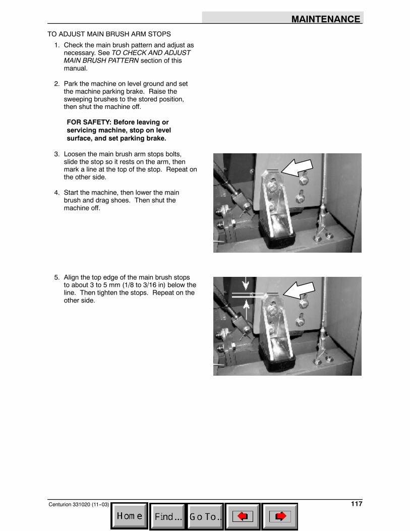
MAINTENANCE
117Centurion 331020 (11--03)
TO ADJUST MAIN BRUSH ARM STOPS
1. Check the main brush pattern and adjust asnecessary. See TO CHECK AND ADJUSTMAIN BRUSH PATTERN section of thismanual.
2. Park the machine on level ground and setthe machine parking brake. Raise thesweeping brushes to the stored position,then shut the machine off.
FOR SAFETY: Before leaving orservicing machine, stop on levelsurface, and set parking brake.
3. Loosen the main brush arm stops bolts,slide the stop so it rests on the arm, thenmark a line at the top of the stop. Repeat onthe other side.
4. Start the machine, then lower the mainbrush and drag shoes. Then shut themachine off.
5. Align the top edge of the main brush stopsto about 3 to 5 mm (1/8 to 3/16 in) below theline. Then tighten the stops. Repeat on theother side.
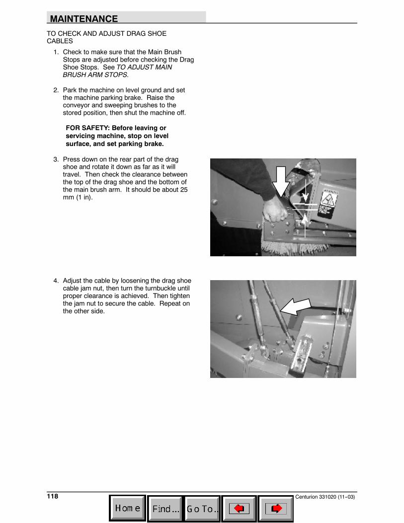
MAINTENANCE
Centurion 331020 (11--03)118
TO CHECK AND ADJUST DRAG SHOECABLES
1. Check to make sure that the Main BrushStops are adjusted before checking the DragShoe Stops. See TO ADJUST MAINBRUSH ARM STOPS.
2. Park the machine on level ground and setthe machine parking brake. Raise theconveyor and sweeping brushes to thestored position, then shut the machine off.
FOR SAFETY: Before leaving orservicing machine, stop on levelsurface, and set parking brake.
3. Press down on the rear part of the dragshoe and rotate it down as far as it willtravel. Then check the clearance betweenthe top of the drag shoe and the bottom ofthe main brush arm. It should be about 25mm (1 in).
4. Adjust the cable by loosening the drag shoecable jam nut, then turn the turnbuckle untilproper clearance is achieved. Then tightenthe jam nut to secure the cable. Repeat onthe other side.
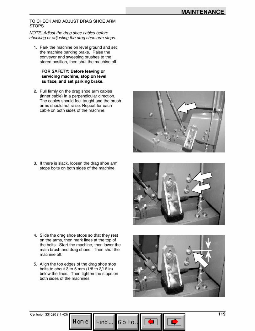
MAINTENANCE
119Centurion 331020 (11--03)
TO CHECK AND ADJUST DRAG SHOE ARMSTOPS
NOTE: Adjust the drag shoe cables beforechecking or adjusting the drag shoe arm stops.
1. Park the machine on level ground and setthe machine parking brake. Raise theconveyor and sweeping brushes to thestored position, then shut the machine off.
FOR SAFETY: Before leaving orservicing machine, stop on levelsurface, and set parking brake.
2. Pull firmly on the drag shoe arm cables(inner cable) in a perpendicular direction.The cables should feel taught and the brusharms should not raise. Repeat for eachcable on both sides of the machine.
3. If there is slack, loosen the drag shoe armstops bolts on both sides of the machine.
4. Slide the drag shoe stops so that they reston the arms, then mark lines at the top ofthe bolts. Start the machine, then lower themain brush and drag shoes. Then shut themachine off.
5. Align the top edges of the drag shoe stopbolts to about 3 to 5 mm (1/8 to 3/16 in)below the lines. Then tighten the stops onboth sides of the machines.

MAINTENANCE
Centurion 331020 (11--03)120
SKIRTS AND SEALS
BRUSH COMPARTMENT SIDE SKIRT
The brush compartment skirt is located at the rearof the brush compartment. The proper adjustmentfor the skirt is 65 mm (2.5 in) from the ground.(Measured with the hopper and water tankempty).
Check the skirt for wear or damage daily.
WARNING: Brush linkage pinch points.Stay clear when linkage is moving.
BRUSH COMPARTMENT REAR SKIRT
The brush compartment skirt is located at the rearof the brush compartment. The properadjustment for the skirt is 65 mm (2.5 in) from theground. (Measured with the hopper and watertank empty).
Check the skirt for wear or damage daily.
TOP CONVEYOR SKIRTS
The conveyor has a lip skirt located at the top ofthe conveyor and two side skirts on each side ofthe conveyor. The top conveyor side skirts shouldoverlap the hopper skirts about 12.7 mm (0.5 in)when the conveyor is lowered into the sweepingposition.
Check the skirts for wear or damage and properfit daily.
WARNING: Conveyor throws debris.Conveyor pinch point. Stay clear whenin operation.
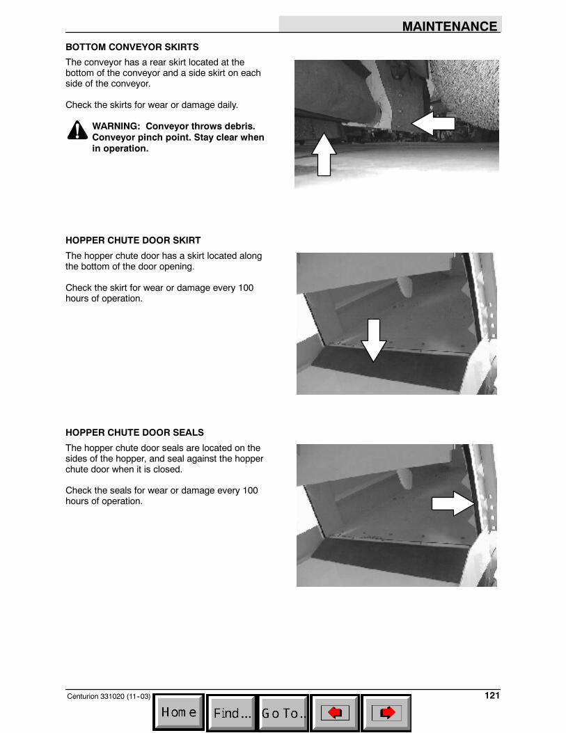
MAINTENANCE
121Centurion 331020 (11--03)
BOTTOM CONVEYOR SKIRTS
The conveyor has a rear skirt located at thebottom of the conveyor and a side skirt on eachside of the conveyor.
Check the skirts for wear or damage daily.
WARNING: Conveyor throws debris.Conveyor pinch point. Stay clear whenin operation.
HOPPER CHUTE DOOR SKIRT
The hopper chute door has a skirt located alongthe bottom of the door opening.
Check the skirt for wear or damage every 100hours of operation.
HOPPER CHUTE DOOR SEALS
The hopper chute door seals are located on thesides of the hopper, and seal against the hopperchute door when it is closed.
Check the seals for wear or damage every 100hours of operation.
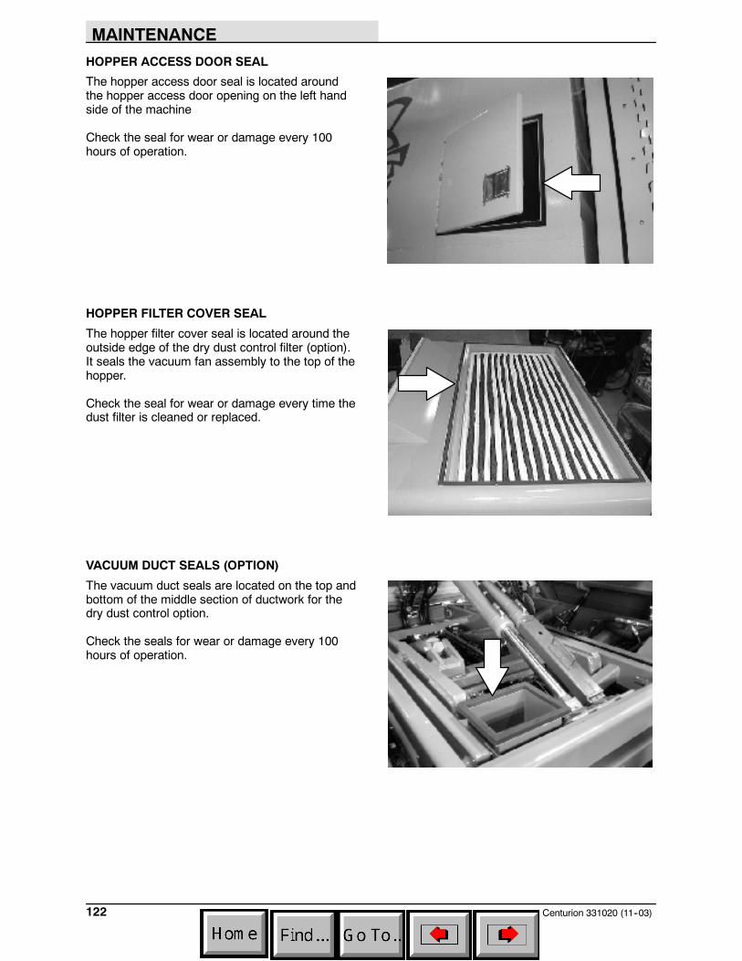
MAINTENANCE
Centurion 331020 (11--03)122
HOPPER ACCESS DOOR SEAL
The hopper access door seal is located aroundthe hopper access door opening on the left handside of the machine
Check the seal for wear or damage every 100hours of operation.
HOPPER FILTER COVER SEAL
The hopper filter cover seal is located around theoutside edge of the dry dust control filter (option).It seals the vacuum fan assembly to the top of thehopper.
Check the seal for wear or damage every time thedust filter is cleaned or replaced.
VACUUM DUCT SEALS (OPTION)
The vacuum duct seals are located on the top andbottom of the middle section of ductwork for thedry dust control option.
Check the seals for wear or damage every 100hours of operation.
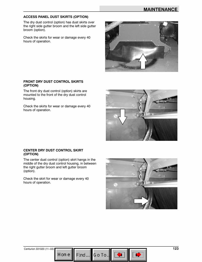
MAINTENANCE
123Centurion 331020 (11--03)
ACCESS PANEL DUST SKIRTS (OPTION)
The dry dust control (option) has dust skirts overthe right side gutter broom and the left side gutterbroom (option).
Check the skirts for wear or damage every 40hours of operation.
FRONT DRY DUST CONTROL SKIRTS(OPTION)
The front dry dust control (option) skirts aremounted to the front of the dry dust controlhousing.
Check the skirts for wear or damage every 40hours of operation.
CENTER DRY DUST CONTROL SKIRT(OPTION)
The center dust control (option) skirt hangs in themiddle of the dry dust control housing, in betweenthe right gutter broom and left gutter broom(option).
Check the skirt for wear or damage every 40hours of operation.
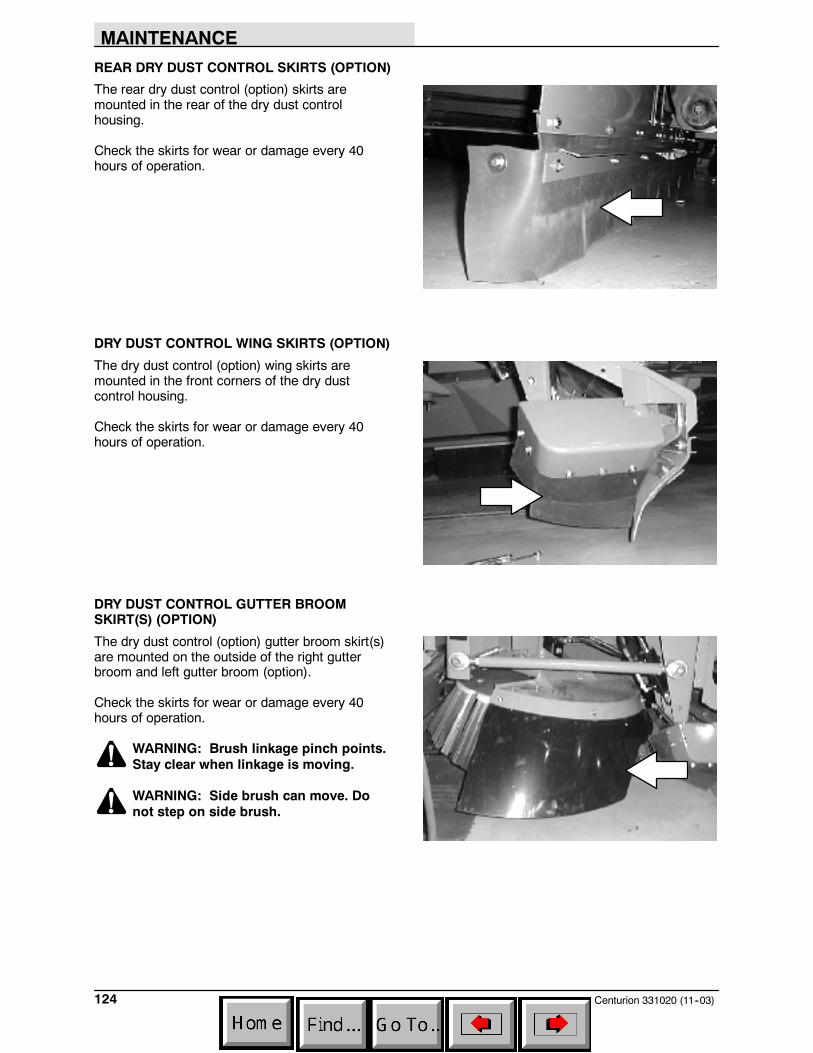
MAINTENANCE
Centurion 331020 (11--03)124
REAR DRY DUST CONTROL SKIRTS (OPTION)
The rear dry dust control (option) skirts aremounted in the rear of the dry dust controlhousing.
Check the skirts for wear or damage every 40hours of operation.
DRY DUST CONTROL WING SKIRTS (OPTION)
The dry dust control (option) wing skirts aremounted in the front corners of the dry dustcontrol housing.
Check the skirts for wear or damage every 40hours of operation.
DRY DUST CONTROL GUTTER BROOMSKIRT(S) (OPTION)
The dry dust control (option) gutter broom skirt(s)are mounted on the outside of the right gutterbroom and left gutter broom (option).
Check the skirts for wear or damage every 40hours of operation.
WARNING: Brush linkage pinch points.Stay clear when linkage is moving.
WARNING: Side brush can move. Donot step on side brush.
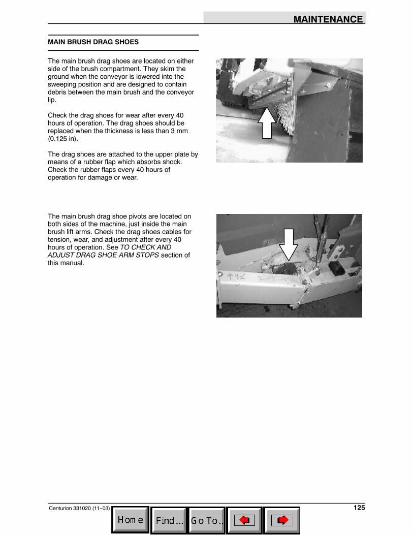
MAINTENANCE
125Centurion 331020 (11--03)
MAIN BRUSH DRAG SHOES
The main brush drag shoes are located on eitherside of the brush compartment. They skim theground when the conveyor is lowered into thesweeping position and are designed to containdebris between the main brush and the conveyorlip.
Check the drag shoes for wear after every 40hours of operation. The drag shoes should bereplaced when the thickness is less than 3 mm(0.125 in).
The drag shoes are attached to the upper plate bymeans of a rubber flap which absorbs shock.Check the rubber flaps every 40 hours ofoperation for damage or wear.
The main brush drag shoe pivots are located onboth sides of the machine, just inside the mainbrush lift arms. Check the drag shoes cables fortension, wear, and adjustment after every 40hours of operation. See TO CHECK ANDADJUST DRAG SHOE ARM STOPS section ofthis manual.
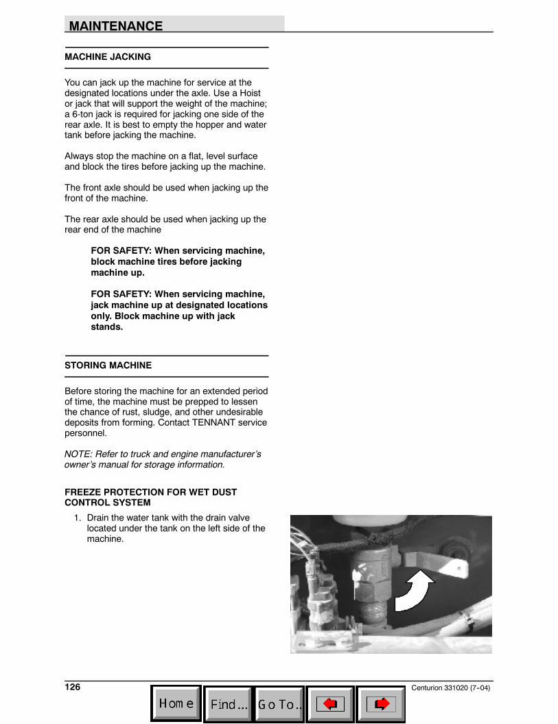
MAINTENANCE
Centurion 331020 (7--04)126
MACHINE JACKING
You can jack up the machine for service at thedesignated locations under the axle. Use a Hoistor jack that will support the weight of the machine;a 6-ton jack is required for jacking one side of therear axle. It is best to empty the hopper and watertank before jacking the machine.
Always stop the machine on a flat, level surfaceand block the tires before jacking up the machine.
The front axle should be used when jacking up thefront of the machine.
The rear axle should be used when jacking up therear end of the machine
FOR SAFETY: When servicing machine,block machine tires before jackingmachine up.
FOR SAFETY: When servicing machine,jack machine up at designated locationsonly. Block machine up with jackstands.
STORING MACHINE
Before storing the machine for an extended periodof time, the machine must be prepped to lessenthe chance of rust, sludge, and other undesirabledeposits from forming. Contact TENNANT servicepersonnel.
NOTE: Refer to truck and engine manufacturer’sowner’s manual for storage information.
FREEZE PROTECTION FOR WET DUSTCONTROL SYSTEM
1. Drain the water tank with the drain valvelocated under the tank on the left side of themachine.
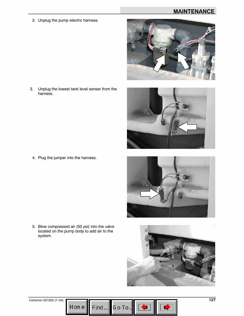
MAINTENANCE
127Centurion 331020 (7--04)
2. Unplug the pump electric harness.
3. Unplug the lowest tank level senser from theharness.
4. Plug the jumper into the harness.
5. Blow compressed air (50 psi) into the valvelocated on the pump body to add air to thesystem.
MAINTENANCE
Centurion 331020 (7--04)128
6. Have an assistant use the touch panel locatedinside the cab of the machine to cycle througheach of the four water system modes until nowater comes from the nozzles.
7. When completed, return machine to stockconfiguration.
TRANSPORTING THE MACHINE
Transport the Centurion only on a suitable ”lowboy” trailer with proper load rating for supportingthe machine weight. Empty hopper and watertank before loading. Load only on level surface bya qualified driver trained in the use of the safetrailer loading and unloading procedures. Keepbystanders clear when loading. Set the parkingbrake and block the machine tires. Tie down themachine to the truck or trailer before transporting.Consult applicable Federal Motor Carrier SafetyAdministration (FMCSA) Safety Regulations forproper cargo securing and inspection procedure.
FOR SAFETY: When loading/unloadingmachine onto/off truck or trailer; turn offmachine, use truck or trailer that willsupport the weight of the machine. Setparking brake after machine is loaded.Block machine tires. Tie machine downto truck or trailer.
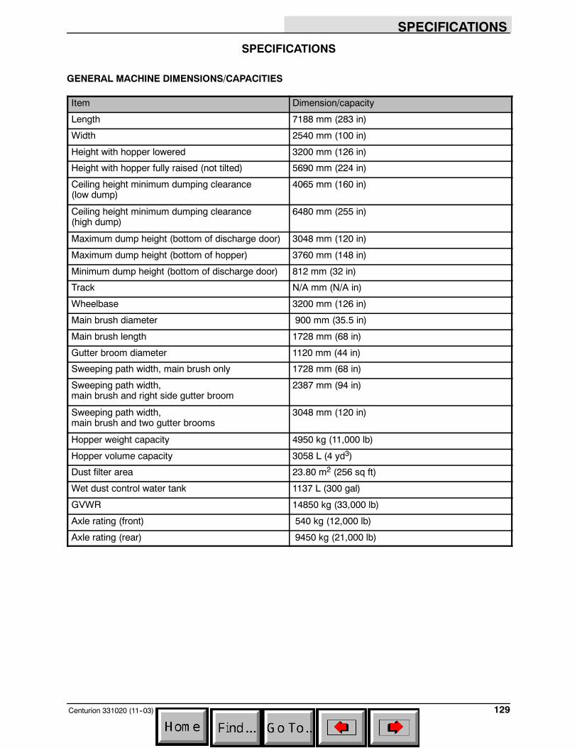
SPECIFICATIONS
129Centurion 331020 (11--03)
SPECIFICATIONS
GENERAL MACHINE DIMENSIONS/CAPACITIES
Item Dimension/capacity
Length 7188 mm (283 in)
Width 2540 mm (100 in)
Height with hopper lowered 3200 mm (126 in)
Height with hopper fully raised (not tilted) 5690 mm (224 in)
Ceiling height minimum dumping clearance(low dump)
4065 mm (160 in)
Ceiling height minimum dumping clearance(high dump)
6480 mm (255 in)
Maximum dump height (bottom of discharge door) 3048 mm (120 in)
Maximum dump height (bottom of hopper) 3760 mm (148 in)
Minimum dump height (bottom of discharge door) 812 mm (32 in)
Track N/A mm (N/A in)
Wheelbase 3200 mm (126 in)
Main brush diameter 900 mm (35.5 in)
Main brush length 1728 mm (68 in)
Gutter broom diameter 1120 mm (44 in)
Sweeping path width, main brush only 1728 mm (68 in)
Sweeping path width,main brush and right side gutter broom
2387 mm (94 in)
Sweeping path width,main brush and two gutter brooms
3048 mm (120 in)
Hopper weight capacity 4950 kg (11,000 lb)
Hopper volume capacity 3058 L (4 yd3)
Dust filter area 23.80 m2 (256 sq ft)
Wet dust control water tank 1137 L (300 gal)
GVWR 14850 kg (33,000 lb)
Axle rating (front) 540 kg (12,000 lb)
Axle rating (rear) 9450 kg (21,000 lb)
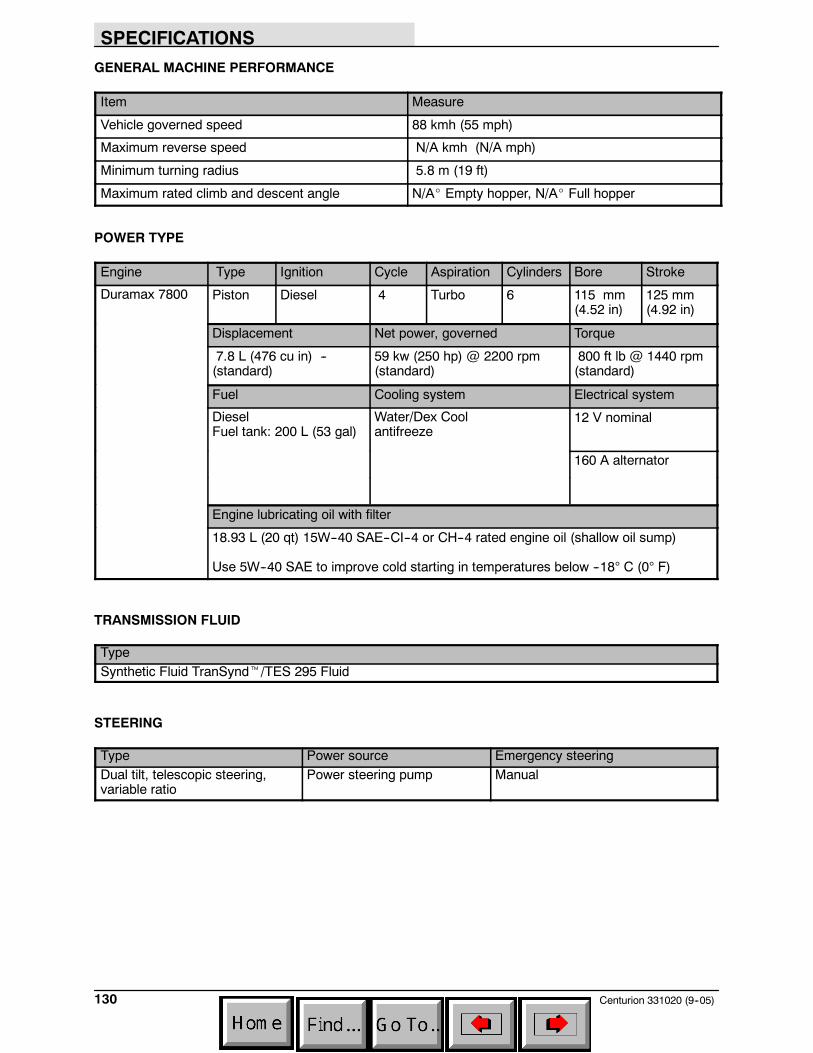
SPECIFICATIONS
Centurion 331020 (9--05)130
GENERAL MACHINE PERFORMANCE
Item Measure
Vehicle governed speed 88 kmh (55 mph)
Maximum reverse speed N/A kmh (N/A mph)
Minimum turning radius 5.8 m (19 ft)
Maximum rated climb and descent angle N/A_ Empty hopper, N/A_ Full hopper
POWER TYPE
Engine Type Ignition Cycle Aspiration Cylinders Bore Stroke
Duramax 7800 Piston Diesel 4 Turbo 6 115 mm(4.52 in)
125 mm(4.92 in)
Displacement Net power, governed Torque
7.8 L (476 cu in) --(standard)
59 kw (250 hp) @ 2200 rpm(standard)
800 ft lb @ 1440 rpm(standard)
Fuel Cooling system Electrical system
DieselFuel tank: 200 L (53 gal)
Water/Dex Coolantifreeze
12 V nominal
160 A alternator
Engine lubricating oil with filter
18.93 L (20 qt) 15W--40 SAE--CI--4 or CH--4 rated engine oil (shallow oil sump)
Use 5W--40 SAE to improve cold starting in temperatures below --18° C (0° F)
TRANSMISSION FLUID
TypeSynthetic Fluid TranSyndt/TES 295 Fluid
STEERING
Type Power source Emergency steeringDual tilt, telescopic steering,variable ratio
Power steering pump Manual
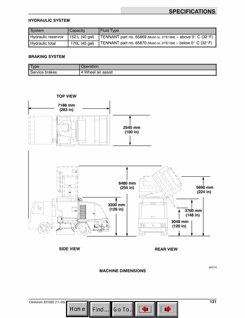
SPECIFICATIONS
131Centurion 331020 (11--03)
HYDRAULIC SYSTEM
System Capacity Fluid Type
Hydraulic reservoir 152 L (40 gal) TENNANT part no. 65869 (Mobil no. DTE18M) -- above 0_ C (32_F)
Hydraulic total 170L (45 gal) TENNANT part no. 65870 (Mobil no. DTE13M) -- below 0_ C (32_F)
BRAKING SYSTEM
Type OperationService brakes 4 Wheel air assist
2540 mm(100 in)
SIDE VIEW
7188 mm(283 in)
TOP VIEW
6480 mm(255 in) 5690 mm
(224 in)
REAR VIEW
3760 mm(148 in)
3048 mm(120 in)
3200 mm(126 in)
353773
MACHINE DIMENSIONS

SPECIFICATIONS
Centurion 331020 (7--04)132
INDEX
133Centurion 331020 (9--05)
Numbers
4--way warning lights, 24
A
Activate park brake alarm, 44
Air brake, Pressure gauge, 23
Air brake pressure gauge, 23
AlarmsActivate park brake, 44Check hydraulic filter alarm, 44Conveyor not back, 42Conveyor stall, 58Conveyor stall alarm, 42Reduce engine RPM alarm, 43, 44Hopper fire, 43Hopper up error, 42Hydraulic fluid low alarm, 46Machine not level , 46Overspeed engine , 45Release E--stop, 45Shake filter , 45Shake filter, 58Tank low, pump off, 43
Arm stops, 116, 117, 118, 119
B
BarsHopper lift support, 41Hopper tilt support, 41
Belts, Conveyor, 100
Brakes, System specifications, 131
Bright headlights light, 23
Brush hourmeter, 26
Brushes, 51–52, 108–113Checking main brush pattern, 112Gutter broom(s), 113Main brush, 108–112Rear skirt, 120Replacing the main brush, 108
C
Capacities, 129
Caps, Hydraulic filler, 85
Center control panel switches, 14, 15
Chart, Maintenance, 75–77
Check hydraulic filter alarm, 44
Contrast Adjustment Knob, 24
Control panelBright headlights light, 23Signal light, 24
Controls, 11–13Activate park brake alarm, 44Air brake pressure gauge, 23Brush hourmeter, 26Check hydraulic filter alarm, 44Contrast Adjustment Knob, 24Conveyor forward switch, 35Conveyor not back alarm, 42Conveyor in switch, 35Conveyor out switch, 36Conveyor reverse switch, 35, 58Conveyor water spray switch, 36Cruise control/Throttle lock, 19Display clock, 25Engine coolant temperature gauge, 22Engine oil pressure gauge, 22Fast idle switch, 18Filter shaker switch, 31Front water spray switch, 37Fuel level gauge, 23Fuse, 38Gutter broom light switch (option), 40Gutter broom speed/pressure adjustment
(option), 39Hopper down switch, 33Hopper dump switch, 34Hopper fire alarm, 43Hopper home switch, 34Hopper up error alarm, 42Hopper up switch, 33Hopper work light switch, 20Hourmeter, 21Hydraulic fluid low alarm, 46Ignition switch, 17Latches, 40Left side gutter broom switch (option), 32, 39Left side gutter broom tilt switch, 39Left side water spray switch (option), 37Machine not level alarm, 46Main broom wear indicator, 29More switch, 26Operation, 17, 42Overspeed engine alarm, 45PTO Hourmeter, 25PTO kill switch , 19PTO switch, 27Pushbutton range selector, 18Rear axle shift control switch, 18Rear work light switch, 20Release E--stop alarm, 45Revolving light switch (option), 40Right side gutter broom switch, 32Right side gutter broom tilt switch, 39Right side instrument console, 20Right side water spray switch, 37
INDEX
Centurion 331020 (9--05)134
Shake filter alarm, 45Speedometer, 21Start up screen, 25Super sweep switch, 29Sweep mode switch, 29Sweep switch, 28Symbols, 10–12Tachometer, 21Tank low, pump off alarm, 43Touch panel, 24Vacuum fan switch, 32Voltmeter, 22Water flow switch, 30Water tank level gauge, 30
ControlsConveyor stall alarm, 42Error--brooms down alarm, 44Operator control switch, 17Preheat light, 24Reduce engine RPM alarm, 43
Conveyor, 100Adjusting the conveyor height, 101Belt, 100Conveyor not back alarm, 42Conveyor stall alarm, 42Paddles, 100, 105Roller, 102Skirts, 100, 105, 120, 121
Conveyor bearings, 82
Conveyor beltFlushing, 102Replacement, 105Splicing the belt, 106Tension springs, 105Tracking adjustment, 103
Conveyor forward switch, 35
Conveyor in switch, 35
Conveyor lift cylinders, 82
Conveyor lift pivots, 82
Conveyor not back alarm, 42
Conveyor out switch, 36
Conveyor reverse switch, 35, 58
Conveyor stall alarm, 42, 58
Conveyor tilt cylinder, 83, 84
Conveyor water spray switch, 36
Cruise control, 19
Cruise control/Throttle lock, 19
Custom sweep settings, Setting the custommode, 54
D
Debris, Conveyor reverse switch, 58
Debris hopper, 96–98
Dimensions, 129
Dimensions, Machine, 131
Disengaging hopper lift support bar, 70–72
Disengaging hopper tilt support bar, 66–67
Display clock, 25
Display screenBrush hourmeter, 26Display clock, 25PTO Hourmeter, 25Start up screen, 25
DoorsCab, Latch, 40Rear, Latch, 40Side, Latch, 40
Drag shoe lift cylinder, 81
Drag shoe pivot, 80
Dry dust controlRear skirts, 124Skirts, 123Wing skirts, 124
Dry dust control (option), Gutter broom skirt(s),124
Dry dust control skirt wing pivots, 83
Dust control, Wet, Filter, 94, 95
Dust control bumpers (option), 79
Dust control skirt cylinder (option), 79
Dust control skirt pivots (option), 79
Dust filter, 96Cleaning, 96
E
Electrical, Fuse, 38
Emptying the hopper, 60–62Machine not level alarm, 46
Engaging hopper lift support bar, 68–70
Engaging the hopper tilt support bar, 64–66
INDEX
135Centurion 331020 (9--05)
Engine, 77, 89–91Air cleaner, 89Cooling system, 88Engine coolant temperature gauge, 22Fuel level gauge, 23Ignition switch, 17Oil pressure gauge, 22Overspeed engine alarm, 45Radiator, 89Specifications, 130Speedometer, 21Tachometer, 21Voltmeter, 22
Engine air cleaner, 89
Engine coolant temperature gauge, 22
Engine oil pressure gauge, 22
Engine speeds, 21
Error--brooms down alarm, 44
F
Fast idle switch, 18
FilterHydraulic, 88Shake alarm, 58
Filter shaker switch, 31
Hopper lower switch, 31
FiltersHydraulic, 85Hydraulic pump load sense, 87Wet dust control, 94, 95
Freeze protection, Wet dust control, 126
Front water spray switch, 37
Fuel level gauge, 23
Fuse, 38
G
GaugesAir brake pressure, 23Engine coolant temperature, 22Engine oil pressure, 22Fuel level gauge, 23Hourmeter, 21Right side instrument console, 20Speedometer, 21Tachometer, 21Voltmeter, 22Water tank level, 30
Gutter broom light switch (option), 40
Gutter broom pivot, 78
Gutter broom skirt(s), 124
Gutter broom speed/pressure adjustment (option),39
Gutter broom support arms, 78
Gutter broom support rods, 78
Gutter broom(s), 113Bristle length, 113Checking and adjusting pattern, 114Checking brush pattern, 113Left side gutter broom tilt switch, 39Replacement, 113Right side gutter broom tilt switch, 39Speed/pressure adjustment (option), 39
Gutter broomsLeft side gutter broom switch (option), 32, 39Right side gutter broom switch, 32
GVWR, 8, 51, 129
H
Heated mirror switch (option), 18
Hopper, 96–98Disengaging hopper lift support bar, 70–72Disengaging hopper tilt support bar, 66–67Down switch, 33Dump switch, 34Dust filter, 96Engaging hopper lift support bar, 68–70Filter cleaning, 96Home switch, 34Hopper fire alarm, 43Hopper up error alarm, 42Lift support bars, 41Thermo-Sentry, 96Tilt support bar, 41Up switch, 33
Hopper access door seal, 122
Hopper chute door seals , 121
Hopper chute door skirt, 121
Hopper down switch, 33Conveyor, 33
Hopper dump switch, 34
Hopper dust filter, Replacing, 97, 98
Hopper filter, Shake filter alarm, 45
Hopper filter cover seal, 122
Hopper fire alarm, 43

INDEX
Centurion 331020 (9--05)136
Hopper home switch, 34
Hopper lift support bars, 41
Hopper lift/tilt, 77
Hopper tilt support bar, 41, 64
Hopper up error alarm, 42
Hopper up switch, 33Conveyor, 33
Hopper work light , Hopper work light switch, 20
Hopper work light switch, 20
Hoses, Hydraulic, 88
Hourmeter, 21
How the machine works, 47
Hydraulic Filter, Check hydraulic filter alarm, 44
Hydraulic fluid, 86Hydraulic fluid low alarm, 46
Hydraulic fluid low alarm, 46, 85
Hydraulic fluid reservoir, 85, 89
Hydraulic hoses, 88
Hydraulic pump load sense filters, 87
Hydraulics, 85–87Cooler, 88Filler cap, 85Filters, 85Fluid, 86Fluid filter, 88Fluid level, 85, 89, 90Hoses, 88Hydraulic fluid low alarm, 85Pump load sense filters, 87Reservoir, 85, 89System specifications, 131
I
Ignition switch, 17
Inclines, Operating on, 63
J
Jack points, 126
Joystick, 8
K
KnobsContrast Adjustment Knob, 24Parking brake, 17
L
Latches, 40Cab doors, 40Rear door, 40Side doors, 40
Left side gutter broom switch (option), 32, 39
Left side gutter broom tilt switch, 39
Left side water spray switch (option), 37
LightsBright headlights, 23Gutter broom light switch (option), 40Preheat , 24Revolving light switch (option), 40Signal, 24
Lubrication, 77
M
Machine, Right side instrument console, 20
Machine components, 9
Machine dimensions, 131
Machine jacking, 126
Machine not level alarm, 46, 63
Machine troubleshooting, 72, 73
Main broom wear indicator, 29
Main brush, 108–112Checking brush pattern, 108, 112Maintenance, 108
Main brush and drag shoe cable and arm stops,116–121
Main brush and drag shoe cylinders, 81
Main brush drag shoes, 125
Main brush idler bearing, 80
Main brush lift cylinder, 81
Main brush support arms, 80
Maintenance, 74Adjusting the main brush pattern, 112Brushes, 108Checking and adjusting gutter broom pattern,
114Conveyor, 100Conveyor belt, Tracking, 103Debris hopper, 96Dry dust control rear skirts, 124Dry dust control skirts, 123Dry dust control wing skirts, 124
INDEX
137Centurion 331020 (9--05)
Engine air cleaner, 89Gutter broom(s), 113Hopper access door seal, 122Hopper chute door seals, 121Hopper chute door skirt, 121Hopper dust filter, 96Hopper filter cover seal, 122Intervals, 75–77LubricationConveyor bearings, 82Conveyor lift cylinders, 82Conveyor lift pivots, 82Conveyor tilt cylinder, 83, 84Drag shoe lift cylinder, 81Drag shoe pivot, 80Dry dust control skirt wing pivots, 83Dust control bumper pivots (option), 79Dust control skirt cylinder, 79Dust control skirt pivots (option), 79Engine, 77, 89Gutter broom pivot, 78Gutter broom support arms, 78Gutter broom support rods, 78Hopper lift/tilt, 77Main brush and drag shoe cylinders, 81Main brush idler bearing, 80Main brush lift cylinder, 81Main brush support arms, 80Propulsion shaft slip joint, 83
Main brush and drag shoe cable arm stops, 116Main brush drag shoes, 125Radiator, 89Recommended, 8Replacing gutter broom(s), 113Replacing the conveyor belt, 105Skirts and seals, 120Transmission access, 90Vacuum duct seals, 122Wet dust control system, 94
Maintenance chart, 75–77
More switch, 26
O
Operation, 8–60
Operation on inclines, 63
Operator control switch, 17
Operator Responsibility, 8
OptionsDry dust controlRear skirts, 124Skirts, 123Wing skirts, 124
Dry dust control skirt wing pivots, 83Dust control bumpers, 79Dust control skirt cylinder, 79Dust control skirt pivots, 79Gutter broom dust control skirt(s), 124Gutter broom light switch, 40Gutter broom speed/pressure adjustment, 39Heated mirror switch, 18Hydraulic fluid low alarm, 46Left side gutter broom tilt switch, 39Rear work light switch, 20Revolving light switch, 40Right side gutter broom tilt switch, 39Vacuum duct seals, 122Wet dust control, Filter, 94, 95
Overspeed engine alarm, 45
P
Parking brake, Activate park brake alarm, 44
Parking brake knob, 17
Power take offPTO kill switch , 19Reduce engine RPM alarm, 43Release E--stop alarm, 45
Pre and post operation checklist, 48–51
Preheat , Light, 24
Preheat light, 24
Propulsion shaft slip joint, 83
PTO Hourmeter, 25
PTO kill switch, 19
PTO switch, 27Error--brooms down alarm, 44
Pushbutton range selector, 18Digital display, 18
INDEX
Centurion 331020 (9--05)138
R
Radiator, 89Exterior, 88
Rear axle shift control switch, 18
Rear skirts, Dry dust control, 124
Rear work light, Rear work light switch , 20
Rear work light switch, 20
Reduce engine RPM alarm, 43
Release E--stop alarm, 45
Reservoir, hydraulic, 85, 89
Revolving light switch (option), 40
Right hand steering instrument console, 11
Right side gutter broom switch, 32
Right side gutter broom tilt switch, 39
Right side instrument console, 20
Right side water spray switch, 37
S
SafetyDisengaging hopper lift support bar, 70–72Disengaging hopper tilt support bar, 66–67Engaging hopper lift support bar, 68–70Hopper lift support bars, 41Hopper tilt support bar, 41Labels, 6Precautions, 4
Seals, 120–122
Setting the custom mode, 54
Shake filter alarm, 45, 58
Side brush, 52
Signal light, 24
Skirts, 120Brush compartment, 120Conveyor, 120, 121Dry dust control, 123
Specifications, 129–130Braking system, 131GVWR, 129Hydraulic system, 131Machine capacities, 129Machine dimensions, 129Machine performance, 130Power type, 130Steering, 130
Speedometer, 17, 21
Start up screen, 25Brush hourmeter, 26PTO Hourmeter, 25
Starting the machine, 49–51
Steering, Specifications, 130
Stop sweeping, 59
Stopping the machine, 62–64
Storing machine, 126Freeze protection, 126
Super sweep switch, 29
Sweep mode, Super sweep switch, 29
Sweep mode switch, 29
Sweep switch, 28
Sweeping, 57–60Filling the water tank, 55–58
Sweeping and brush information, 51–52
SwitchesConveyor forward, 35Conveyor in, 35Conveyor out, 36Conveyor reverse, 35, 58Conveyor water spray, 36Fast idle switch, 18Filter shaker switch, 31Front water spray, 37Gutter broom light switch (option), 40Heated mirror (option), 18Hopper down switch, 33Hopper dump, 34Hopper home, 34Hopper up switch, 33Hopper work light switch, 20Left side gutter broom switch (option), 32, 39Left side gutter broom tilt switch, 39Left side water spray (option), 37Main broom wear indicator, 29More switch, 26Operator control switch, 17Power takeoff , 25PTO, 27PTO kill switch, 19Rear axle shift control switch, 18Rear work light switch, 20Revolving light switch (option), 40Right side gutter broom switch, 32Right side gutter broom tilt switch, 39Right side wate spray, 37Super sweep switch, 29Sweep, 28Sweep mode switch, 29Touch panel, 24Vacuum fan switch, 32Water flow switch, 30

INDEX
139Centurion 331020 (9--05)
T
Tachometer, 21Engine speeds, 21
Tank low, pump off alarm, 43
Thermo-sentry, 96
Throttle Lock, 19
To adjust main brush arm stops, 117
To check and adjust drag shoe arm stops, 118,119
To check main brush arm stops, 116
Touch PanelConveyor control screenConveyor forward switch, 35Conveyor in switch, 35Conveyor out switch, 36Conveyor reverse switch, 35
Hopper control screenHopper down switch, 33Hopper dump switch, 34Hopper home switch, 34Hopper up switch, 33
Left side water spray switch (option), 37PTO switch, 27Right side gutter broom switch, 32Right side water spray switch, 37Sweep mode screenMain broom wear indicator, 29Super sweep switch, 29Vacuum fan switch, 32
Sweep switch, 28
Touch panel, 24Sweep mode screen, Sweep mode switch, 29Conveyor water spray switch, 36Idle speed, 21Left side gutter broom switch (option), 32, 39Low speed, 21More switch, 26Power takeoff switch, 27Sweep mode screenFilter shaker switch, 31Sweep mode switch, 29Water flow switch, 30
Water tank level gauge, Filter shaker switch, 30
Touch panel, 16
Touch panel , Full power, 21
Transmission, Pushbutton range selector, 18
Transmission Access, 90
Transmission Fluid, 130Specifications, 130
Transporting machine, 128
Travel speed, 130
Troubleshooting, 72, 73
Turning radius, 130
U
Upper control panel switches, 12, 13
V
Vacuum duct seals, 122
Vacuum fan, Vacuum fan switch, 32
Vacuum fan switch, 32
Valve, Water, 95
Voltmeter, 22
W
Water flow switch, 30
Water pump, Tank low, pump off alarm, 43
Water tank level gauge, 30
Water Valve, 95
Weight limit, 8, 51, 129
Wet dust control filterFilter, 94, 95Water Valve, 95
Wet dust control system, 94Front water spray switch, 37Water flow switch, 30
Wing skirts, Dry dust control, 124

INDEX
Centurion 331020 (9--05)140