cequent installation instructions towing tip, or visit … instructions ... and requirements for...
TRANSCRIPT

Cequent™ Performance Products, Inc.www.cequentgroup.com Technical Assistance: [email protected]
Installation InstructionsPART NUMBERS: 24931, 60369, 77318
©2015 Cequent™ Performance Products, Inc. - Printed in Mexico Sheet 1 of 15 24931NP 9-29-15 Rev. B
To prevent SERIOUS INJURY, DEATH or PROPERTY DAMAGE:
• ALWAYS read, understand and follow warnings and instructions
for your hitch BEFORE installation. Keep for future reference.
• DO NOT cut, weld or modify this receiver.
• CHECK all fasteners are tight and your hitch is securely mounted
to your vehicle periodically.
• ALWAYS read, understand and follow all warnings and
instructions for your vehicle and for other accessories you will use
with your hitch BEFORE use.
• LOAD the trailer heavier in front.
• DO NOT exceed lower of towing vehicle manufacturer’s rating or:
• ALWAYS wear your seatbelt.
• SLOW DOWN when towing, NEVER exceed any posted speed limit.
• If EXCESS SWAY occurs, take your foot off the gas pedal and hold
the steering wheel as steady as possible. DO NOT apply your
brakes and DO NOT speed up.
Hitch Type Max Gross Trailer Weight
Max Tongue Weight
Weight Carrying 2000 lb. (908 kg) 200 lb. (90.8 kg)
Weight Distributing X X
Scan for safe towing tip, or visit http://www.cequentgroup.com/qr-product.aspx
LIMITED LIFETIME WARRANTY
1. Limited Lifetime Warranty (“Warranty”). Cequent Performance Products, Inc. ("We",“Us” or “Our”) warrants to the original consumer purchaser only ("You" or “Your”) that theproduct will be free from material defects in both material and workmanship, ordinary wearand tear excepted. The Warranty is valid only if (a) the products are returned to Us forinspection and testing; (b) Our inspection discloses to Our satisfaction that any allegednonconformance are material and have not been caused by misuse, neglect, wear and tear,improper installation, unsuitable storage, improper repair, alteration, or accident; and (c) theproducts were installed, maintained and used in accordance with Our instructions. THEWARRANTY IS MADE IN LIEU OF ALL OTHER WARRANTIES, EXPRESS ORIMPLIED (OTHER THAN THE WARRANTY OF TITLE AS PROVIDED BY THEUNIFORM COMMERCIAL CODE IN EFFECT IN MICHIGAN), INCLUDINGWITHOUT LIMITATION, ANY WARRANTIES OF MERCHANTABILITY OR FITNESSFOR A PARTICULAR PURPOSE, SAID WARRANTIES BEING EXPRESSLYDISCLAIMED.
2. Obligations of Purchaser. To make a Warranty claim, contact Us at our principal address of47912 Halyard Drive, Suite 100, Plymouth, MI 48170, 1-800-632-3290, identify the productby model number, and follow the claim instructions that will be provided. Any returnedproduct that is replaced by Us becomes our property. You may be responsible for returnshipping costs. Please retain your purchase receipt to verify date of purchase and that Youare the original consumer purchaser. The product and the purchase receipt must be providedto Us in order to process Your Warranty claim.
3. Exclusive Remedy. Product replacement is Your sole and exclusive remedy under thisWarranty. We shall not be liable for service or labor charges incurred in removing orreplacing a product. IN NO EVENT WILL WE BE RESPONSIBLE FOR ANY INDIRECT,SPECIAL, CONSEQUENTIAL OR PUNITIVE DAMAGES.
4. Assumption of Risk. You acknowledge and agree that any use of the product for anypurpose other than the specified use(s) stated in the product instructions is at Your own risk.
5. Governing Law. This Warranty gives You specific legal rights, and You also may haveother rights which vary from state to state. This Warranty is governed by the laws of theState of Michigan, without regard to rules pertaining to conflicts of law. The state courtslocated in Oakland County, Michigan shall have exclusive jurisdiction for any disputesrelating to this Warranty.
Rev 9/2014

Equipment Required:
CequentCequentCequentCequent™™™™ Performance Products, Inc.Performance Products, Inc.Performance Products, Inc.Performance Products, Inc.www.cequentgroup.com Technical Assistance: [email protected]
Installation InstructionsPART NUMBERS: 24931, 60369, 77318
Applications:
Years Make Models
2014-Current* Infiniti Q50
*Visit our website for the most up to date information regarding application years and trim levels.
RatchetTorque Wrench
Safety Glasses
Sockets
12 mm16 mm11/16‘’ Flat
Head Screw Driver
DO NOT EXCEED LOWER OF TOWING VEHICLE MANUFACTURER’S RATING OR:
Hitch Type Max Gross Trailer Weight Max Tongue Weight
Weight Carrying 2000 lb. (908 kg) 200 lb. (90.8 kg)
Weight Distributing X X
Representative Vehicle Photo
©2015 Cequent™ Performance Products, Inc. - Printed in Mexico Sheet 2 of 15 24931NP 9-29-15 Rev. B
Installation Time: 40 Min.
The time listed above is the average time for professional installers. If you do not feel comfortable performing this installation on your own or are in need of assistance, please contact a professional installer.
Hitch Illustration
Front of Vehicle
Socket Extension
Die Grinder
Lubricant or Soapy water
Paint orPrimer
Step bit or

1. Remove tie down bracket on passenger side frame rail if present, to enlarge access hole.2. Lower exhaust by removing (3) bolts attached to rubber isolator hanger bracket both sides. Support vehicle exhaust. For additional access remove next forward isolators. Spraying a lubricant or soapy
water on the metal hanger rod and the rubber isolator helps removal.3. Using a 1” step bit or die grinder enlarge the access hole on bottom of frame to allow carriage bolt and spacer access to frame rail, both sides.4. Feed the coiled end of the pull wire through rearward hole and out the access hole. Attach spacer and carriage bolt onto pull wire and feed the fasteners into location through the hole. Push the
fasteners back into the frame rails with the pull wire attached, to allow the hitch to go into position. Leave pull wires attached. Repeat the same process on the both frame rails. 5. Raise the hitch into position, feeding the end of the pull through the holes in the hitch. Then pull the fasteners back through the frame rails and hitch brackets. Repeat the same process on both frame
rails. 6. Feed conical washer over pull wire, using the washer to hold the bolt in place remove the pull wires and attach the hex nut. Tighten to hold hitch in place, repeat with all fasteners.
7. Tighten all 7/16 GR5 fasteners with torque wrench to 50 Lb.-Ft. (68 N*M)
8. Raise exhaust back into position, spraying a lubricant or soapy water on the metal hanger rod, if removed in step 2. Then reinstall the bolts into the rubber isolator hanger bracket.9. Paint or touch up any bare metal created while enlarging access hole on bottom of the frame rail.10. Reattach the tie down bracket, if remove in step 1.
©2015 Cequent™ Performance Products, Inc. - Printed in Mexico Sheet 3 of 15 24931NP 9-29-15 Rev. B
Note: check hitch frequently, making sure all fasteners and ball are properly tightened. If hitch is removed, plug all holes in trunk pan or other body panels to prevent entry of water and exhaust fumes. A hitch or ball which has been damaged should be removed and replaced. Observe safety precautions when working beneath a vehicle and wear eye protection. Do not cut access or attachment holes with a torch.
This product complies with safety specifications and requirements for connecting devices and towing systems of the state of New York, V.E.S.C. Regulation V-5 and SAE J684.
Figure 2
① Qty. (4) Carriage bolt 7/16-14 x 1.75 GR5
② Qty. (4) Spacer.250 x 7/8 x3
③ Qty. (4) Conical washer7/16’’
④ Qty. (4) Hex Nut7/16-14 GR2
⑤ Qty. (4) Pull wire 7/16
RearScan for step by step PHOTO installation instruction or visit
http://www.cequentgroup.com/qr-product.aspx
Drawbar must be used in the RISE position only.
Drawbar Kit:3592
Fastener Kit: 24931F
Figure 1
Installation InstructionsPART NUMBERS: 24931, 60369, 77318
Proper torque is needed to keep the hitch secure to the vehicle when towing.
Always wear SAFETY GLASSES when installing hitch
①
②
③④
⑤
Teeth side against hitch
Access hole tobe enlarged
Frame rails
Kink Pull wire to keep spacer independent of bolt
Example of pull wire procedure
(Sold separately)

©2015 Cequent™ Performance Products, Inc. - Printed in Mexico Sheet 4 of 15 24931NP 9-29-15 Rev. B
1. Remove tie down bracket on passenger side frame rail if present, to enlarge access hole.
2. Lower exhaust by removing (3) bolts attached to rubber isolator hanger bracket both sides. Support vehicle exhaust. For additional access remove next forward isolators. Spraying a lubricant or soapy water on the metal hanger rod and the rubber isolator helps removal.
3. Using a 1”step bit or die grinder enlarge the access hole on bottom of frame to allow carriage bolt and spacer access to frame rail, both sides.
4. Feed the coiled end of the pull wire through rearward hole and out the access hole. Attach spacer and carriage bolt onto pull wire and feed the fasteners into location through the hole. Push the fasteners back into the frame rails with the pull wire attached, to allow the hitch to go into position. Leave pull wires attached. Repeat the same process on the both frame rails.
Access hole tobe enlarged
Access hole tobe enlarged

©2015 Cequent™ Performance Products, Inc. - Printed in Mexico Sheet 5 of 15 24931NP 9-29-15 Rev. B
5. Raise the hitch into position, feeding the end of the pull through the holes in the hitch. Then pull the fasteners back through the frame rails and hitch brackets. Repeat the same process on both frame rails.
6. Feed conical washer over pull wire, using the washer to hold the bolt in place remove the pull wires and attach the hex nut. Tighten to hold hitch in place, repeat with all fasteners.
7. Tighten all 7/16 GR5 fasteners with torque wrench to 50 Lb.-Ft. (68 N*M)
Proper torque is needed to keep the hitch secure to the vehicle when towing.
8. Raise exhaust back into position, spraying a lubricant or soapy water on the metal hanger rod, if removed in step 2. Then reinstall the bolts into the rubber isolator hanger bracket.
9. Paint or touch up any bare metal created while enlarging access hole on bottom of the frame rail.
10. Reattach the tie down bracket remove in step 1.

Cequent™ Performance Products, Inc.www.cequentgroup.com Assistance technique : [email protected]
Instructions d’installationNUMÉROS DE PIÈCES :24931, 60369, 77318
©2015 Cequent™ Performance Products, Inc. - Imprimé au Mexique Feuille 6 de 15 24931NP 9-29-15 Rev. B
Pour prévenir les BLESSURES SÉVÈRES, FATALES ou les DOMMAGES
MATÉRIELS :
• TOUJOURS lire, assimiler et observer les avertissements et les instructions relatives à l'attelage AVANT d'installer celui-ci.Conserver la documentation pour référence ultérieure.
• NE PAS découper, percer, souder ni modifier cet attelage-récepteur.
• S'ASSURER régulièrement que toute la visserie est correctementserrée et que l'attelage est monté sur le véhicule en toutesécurité.
• TOUJOURS lire, assimiler et observer tous les avertissements et toutes les instructions relatives au véhicule et aux autresaccessoires utilisés avec l'attelage AVANT l'utilisation.
• PLACER les plus lourdes charges à l'avant de la remorque.• NE PAS excéder les spécifications de charge du fabricant du
véhicule, ni la moins élevée des valeurs suivantes :
• TOUJOURS porter la ceinture de sécurité.• RALENTIR lors du remorquage, ne JAMAIS dépasser la limite de
vitesse signalée.• En cas de BALANCEMENT EXCESSIF, retirer le pied de la pédale
d'accélérateur et maintenir le volant aussi stable que possible. NE PAS appliquer les freins NI accélérer.
Type d'attelage Poids brut max. de la remorque
Poids max. au timon
Sans répartition de charge
2000 lb. (908 kg) 200 lb. (90.8 kg)
Répartition de charge X X
Numérisez pour des conseils de sécurité, ou visitez http://www.cequentgroup.com/qr-product.aspx
GARANTIE À VIE LIMITÉE
1. Garantie à vie limitée (« Garantie »). Cequent Performance Products, Inc. (« Nous », «Notre ») garantit à l’acheteur initial seulement (« Vous », « Votre ») que le produit seraexempt de vices de matières et de fabrication, exception faite de l’usure normale. Cettegarantie n'est valide que si : (a) les produits Nous sont retournés pour inspection et mise àl'essai; (b) Notre inspection révèle, à Notre satisfaction, que toute non conformité présuméeest de nature matérielle et n'a pas été causée par une mauvaise utilisation, la négligence,l'usure, une installation, entreposage ou réparation incorrects, une modification ou unaccident; (c) les produits ont été installés, entretenus et utilisés conformément à Nosinstructions. LA GARANTIE SE SUBSTITUE À TOUTE AUTRE GARANTIE,EXPRESSE OU IMPLICITE (AUTRE QUE LA GARANTIE DE TITRE OFFERTEPAR LE CODE COMMERCIAL UNIFORME AU MICHIGAN), Y COMPRIS, MAISSANS S’Y LIMITER, TOUTES LES GARANTIES RELATIVES À LA QUALITÉMARCHANDE OU L’ADÉQUATION À UN USAGE PARTICULIER, CELLES-CIÉTANT EXPRESSÉMENT REJETÉES.
2. Obligations de l'acheteur. Pour effectuer une réclamation, communiquez avec Nous à notreadresse principale du 47912 Halyard Drive, Suite 100, Plymouth, MI 48170, 1-800-632-3290;n'oubliez pas d'identifier le produit d'après le numéro de modèle et de suivre les directives quivous seront fournies. Tout produit retourné qui est remplacé par Nous devient notrepropriété. Vous serez tenu d’assumer les frais d'expédition de retour. Veuillez conservervotre reçu d’achat afin que nous puissions en vérifier la date et confirmer que Vous êtesl'acheteur initial. Le produit et le reçu d’achat doivent Nous être fournis afin que nouspuissions traiter Votre réclamation.
3. Recours exclusifs. Le remplacement du produit est Votre seul recours en vertu de cetteGarantie. Nous ne sommes pas responsables des frais de service ou de main-d’oeuvreencourus pour le retrait ou la réinstallation d’un produit. SOUS AUCUNE CIRCONSTANCENOUS NE SERONS TENUS RESPONSABLES DES DOMMAGES INDIRECTS,PARTICULIERS, CONSÉCUTIFS OU PUNITIFS.
4. Acceptation des risques. Vous reconnaissez et acceptez que toute utilisation du produit à desfins autres que celle(s) stipulée(s) dans les instructions relatives au produit est faite à vospropres risques.
5. Loi applicable. Cette Garantie Vous confère des droits légaux spécifiques, et il se peut queVous possédiez d’autres droits qui peuvent varier d’une province à l’autre. Cette Garantie estrégie par les lois de l’État du Michigan, abstraction faite des règles relatives aux conflits delois. Les cours de l’État situées dans le comté d’Oakland, Michigan, constituent les autoritésjudiciaires exclusives relativement à tout litige relevant de cette Garantie.Rev 9/2014

CequentCequentCequentCequent™™™™ Performance Products, Inc.Performance Products, Inc.Performance Products, Inc.Performance Products, Inc.www.cequentgroup.com Assistance technique : [email protected]
Instructions d’installationNUMÉROS DE PIÈCES : 24931, 60369, 77318
Applications :
Années Marque Modèles
2015-actuel* Infiniti Q50
*Visitez notre site Web pour obtenir de l'information à jour concernant une annéeet une version particulières.
Équipement requis :
Clé à cliquet
Clé dynamo
métrique
Lunettes de
protectionDouilles
12 mm16 mm11/16” Tournevis à
tête plate
NE PAS EXCÉDER LES SPÉCIFICATIONS DE CHARGE DU FABRICANT DU VÉHICULE, NI LA MOINS ÉLEVÉE DES VALEURS SUIVANTES :
Type d'attelage Poids brut max. de la remorque
Poids max. au timon
Sans répartition de charge
2000 lb. (908 kg) 200 lb. (90.8 kg)
Répartition de charge X X
Photo représentative du véhicule
©2015 Cequent™ Performance Products, Inc. - Imprimé au Mexique Feuille 7 de 15 24931NP 9-29-15 Rev. B
Durée de l'installation : 40 min
La valeur indiquée ci-dessus est la duréemoyenne des installeurs professionnels. Si vous ressentez de l'inconfort à réalisercette installation par vous-même ou sivous avez besoin d'assistance, veuillezcommuniquer avec un installateurprofessionnel.
Illustration de l'attelage
Avant du véhicule
Peintureou couche
de fond
Foretétagé oumeule à rectifier
Lubrifiant ou eau savonneuse
Rallonge de cliquet de 6 po
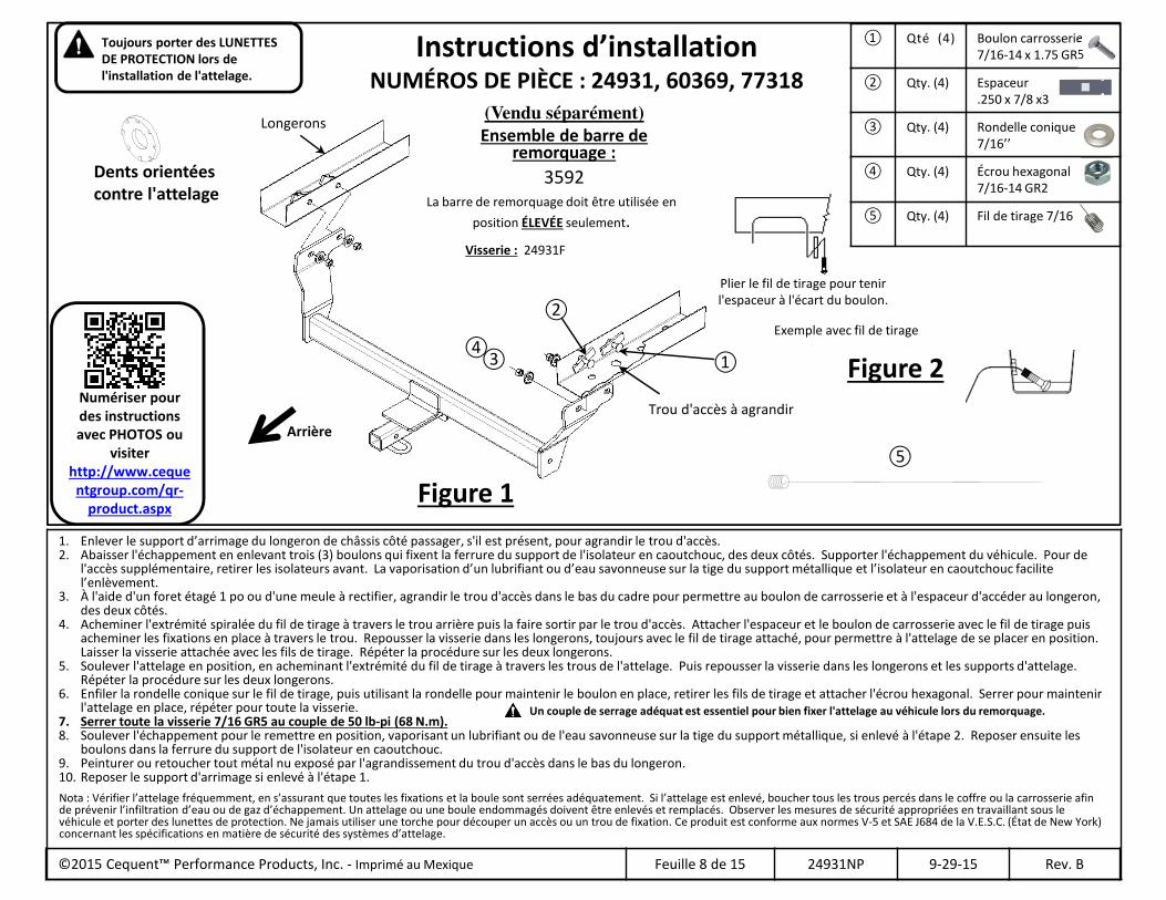
1. Enlever le support d’arrimage du longeron de châssis côté passager, s'il est présent, pour agrandir le trou d'accès.2. Abaisser l'échappement en enlevant trois (3) boulons qui fixent la ferrure du support de l'isolateur en caoutchouc, des deux côtés. Supporter l'échappement du véhicule. Pour de
l'accès supplémentaire, retirer les isolateurs avant. La vaporisation d’un lubrifiant ou d’eau savonneuse sur la tige du support métallique et l’isolateur en caoutchouc facilitel’enlèvement.
3. À l'aide d'un foret étagé 1 po ou d'une meule à rectifier, agrandir le trou d'accès dans le bas du cadre pour permettre au boulon de carrosserie et à l'espaceur d'accéder au longeron, des deux côtés.
4. Acheminer l'extrémité spiralée du fil de tirage à travers le trou arrière puis la faire sortir par le trou d'accès. Attacher l'espaceur et le boulon de carrosserie avec le fil de tirage puisacheminer les fixations en place à travers le trou. Repousser la visserie dans les longerons, toujours avec le fil de tirage attaché, pour permettre à l'attelage de se placer en position. Laisser la visserie attachée avec les fils de tirage. Répéter la procédure sur les deux longerons.
5. Soulever l'attelage en position, en acheminant l'extrémité du fil de tirage à travers les trous de l'attelage. Puis repousser la visserie dans les longerons et les supports d'attelage. Répéter la procédure sur les deux longerons.
6. Enfiler la rondelle conique sur le fil de tirage, puis utilisant la rondelle pour maintenir le boulon en place, retirer les fils de tirage et attacher l'écrou hexagonal. Serrer pour maintenirl'attelage en place, répéter pour toute la visserie.
7. Serrer toute la visserie 7/16 GR5 au couple de 50 lb-pi (68 N.m). 8. Soulever l'échappement pour le remettre en position, vaporisant un lubrifiant ou de l'eau savonneuse sur la tige du support métallique, si enlevé à l'étape 2. Reposer ensuite les
boulons dans la ferrure du support de l'isolateur en caoutchouc.9. Peinturer ou retoucher tout métal nu exposé par l'agrandissement du trou d'accès dans le bas du longeron.10. Reposer le support d'arrimage si enlevé à l'étape 1.
©2015 Cequent™ Performance Products, Inc. - Imprimé au Mexique Feuille 8 de 15 24931NP 9-29-15 Rev. B
Nota : Vérifier l’attelage fréquemment, en s’assurant que toutes les fixations et la boule sont serrées adéquatement. Si l’attelage est enlevé, boucher tous les trous percés dans le coffre ou la carrosserie afin de prévenir l’infiltration d’eau ou de gaz d’échappement. Un attelage ou une boule endommagés doivent être enlevés et remplacés. Observer les mesures de sécurité appropriées en travaillant sous le véhicule et porter des lunettes de protection. Ne jamais utiliser une torche pour découper un accès ou un trou de fixation. Ce produit est conforme aux normes V-5 et SAE J684 de la V.E.S.C. (État de New York) concernant les spécifications en matière de sécurité des systèmes d’attelage.
Figure 2
① Qté (4) Boulon carrosserie 7/16-14 x 1.75 GR5
② Qty. (4) Espaceur.250 x 7/8 x3
③ Qty. (4) Rondelle conique7/16’’
④ Qty. (4) Écrou hexagonal7/16-14 GR2
⑤ Qty. (4) Fil de tirage 7/16
Arrière
Numériser pour des instructions avec PHOTOS ou
visiter http://www.ceque
ntgroup.com/qr-product.aspx
La barre de remorquage doit être utilisée en
position ÉLEVÉE seulement.
Ensemble de barre de remorquage :
3592
Visserie : 24931F
Figure 1
Instructions d’installationNUMÉROS DE PIÈCE : 24931, 60369, 77318
Un couple de serrage adéquat est essentiel pour bien fixer l'attelage au véhicule lors du remorquage.
Toujours porter des LUNETTES DE PROTECTION lors de l'installation de l'attelage.
①
②
③④
⑤
Dents orientées contre l'attelage
Trou d'accès à agrandir
Longerons
Plier le fil de tirage pour tenirl'espaceur à l'écart du boulon.
Exemple avec fil de tirage
(Vendu séparément)

©2015 Cequent™ Performance Products, Inc. - Imprimé au Mexique Feuille 9 de 15 24931NP 9-29-15 Rev. B
1. Enlever le support d’arrimage du longeron de châssis côté passager, s'ilest présent, pour agrandir le trou d'accès.
2. Abaisser l'échappement en enlevant trois (3) boulons qui fixent la ferrure du support de l'isolateur en caoutchouc, des deux côtés. Supporter l'échappementdu véhicule. Pour de l'accès supplémentaire, retirer les isolateurs avant. La vaporisation d’un lubrifiant ou d’eau savonneuse sur la tige du support métallique et l’isolateur en caoutchouc facilite l’enlèvement.
3. À l'aide d'un foret étagé 1 po ou d'une meule à rectifier, agrandir le trou d'accès dans le bas du cadre pour permettre au boulon de carrosserie et à l'espaceur d'accéder au longeron, des deux côtés.
4. Acheminer l'extrémité spiralée du fil de tirage à travers le trou arrièrepuis la faire sortir par le trou d'accès. Attacher l'espaceur et le boulon de carrosserie avec le fil de tirage puis acheminer les fixations en place à travers le trou. Repousser la visserie dans les longerons, toujours avec le fil de tirage attaché, pour permettre à l'attelage de se placer en position. Laisser la visserie attachée avec les fils de tirage. Répéter la procédure surles deux longerons.
Trou d'accès à agrandir
Trou d'accès à agrandir

©2015 Cequent™ Performance Products, Inc. - Imprimé au Mexique Feuille 10 de 15 24931NP 9-29-15 Rev. B
5. Soulever l'attelage en position, en acheminant l'extrémité du fil de tirage à travers les trous de l'attelage. Puisrepousser la visserie dans les longerons et les supports d'attelage. Répéter la procédure sur les deux longerons.
6. Enfiler la rondelle conique sur le fil de tirage, puis utilisant la rondelle pour maintenirle boulon en place, retirer les fils de tirage et attacher l'écrou hexagonal. Serrer pour maintenir l'attelage en place, répéter pour toute la visserie.
7. Serrer toute la visserie 7/16 GR5 au couple de 50 lb-pi (68 N.m).
Un couple de serrage adéquat est essentielpour bien fixer l'attelage au véhicule lorsdu remorquage.
8. Soulever l'échappement pour le remettre en position, vaporisant un lubrifiant ou de l'eau savonneuse sur la tige du support métallique, si enlevé à l'étape 2. Reposer ensuite les boulons dans la ferrure du support de l'isolateuren caoutchouc.
9. Peinturer ou retoucher tout métal nu exposé par l'agrandissement du trou d'accès dans le bas du longeron.
10. Reposer le support d'arrimage si enlevé à l'étape 1.
Cequent™ Performance Products, Inc.www.cequentgroup.com Asistencia técnica: [email protected]
Instrucciones de instalaciónNÚMEROS DE PARTES: 24931, 60369, 77318
© 2015 Cequent™ Performance Products, Inc. Impreso en México Hoja 11 de 15 24931NP 9-29-15 Rev. B
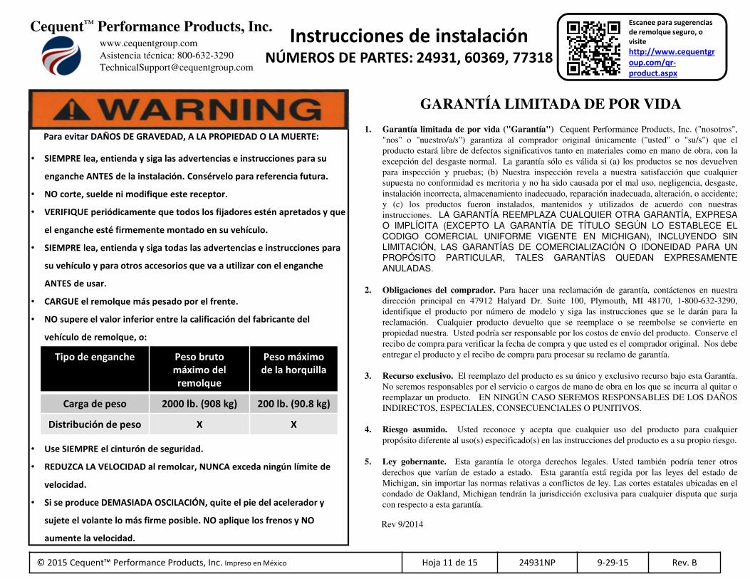
Para evitar DAÑOS DE GRAVEDAD, A LA PROPIEDAD O LA MUERTE:
• SIEMPRE lea, entienda y siga las advertencias e instrucciones para su
enganche ANTES de la instalación. Consérvelo para referencia futura.
• NO corte, suelde ni modifique este receptor.
• VERIFIQUE periódicamente que todos los fijadores estén apretados y que
el enganche esté firmemente montado en su vehículo.
• SIEMPRE lea, entienda y siga todas las advertencias e instrucciones para
su vehículo y para otros accesorios que va a utilizar con el enganche
ANTES de usar.
• CARGUE el remolque más pesado por el frente.
• NO supere el valor inferior entre la calificación del fabricante del
vehículo de remolque, o:
• Use SIEMPRE el cinturón de seguridad.
• REDUZCA LA VELOCIDAD al remolcar, NUNCA exceda ningún límite de
velocidad.
• Si se produce DEMASIADA OSCILACIÓN, quite el pie del acelerador y
sujete el volante lo más firme posible. NO aplique los frenos y NO
aumente la velocidad.
Tipo de enganche Peso bruto máximo del remolque
Peso máximo de la horquilla
Carga de peso 2000 lb. (908 kg) 200 lb. (90.8 kg)
Distribución de peso X X
Escanee para sugerencias de remolque seguro, o visite
http://www.cequentgroup.com/qr-product.aspx
GARANTÍA LIMITADA DE POR VIDA
1. Garantía limitada de por vida ("Garantía") Cequent Performance Products, Inc. ("nosotros","nos" o "nuestro/a/s") garantiza al comprador original únicamente ("usted" o "su/s") que elproducto estará libre de defectos significativos tanto en materiales como en mano de obra, con laexcepción del desgaste normal. La garantía sólo es válida si (a) los productos se nos devuelvenpara inspección y pruebas; (b) Nuestra inspección revela a nuestra satisfacción que cualquiersupuesta no conformidad es meritoria y no ha sido causada por el mal uso, negligencia, desgaste,instalación incorrecta, almacenamiento inadecuado, reparación inadecuada, alteración, o accidente;y (c) los productos fueron instalados, mantenidos y utilizados de acuerdo con nuestrasinstrucciones. LA GARANTÍA REEMPLAZA CUALQUIER OTRA GARANTÍA, EXPRESAO IMPLÍCITA (EXCEPTO LA GARANTÍA DE TÍTULO SEGÚN LO ESTABLECE ELCODIGO COMERCIAL UNIFORME VIGENTE EN MICHIGAN), INCLUYENDO SINLIMITACIÓN, LAS GARANTÍAS DE COMERCIALIZACIÓN O IDONEIDAD PARA UNPROPÓSITO PARTICULAR, TALES GARANTÍAS QUEDAN EXPRESAMENTEANULADAS.
2. Obligaciones del comprador. Para hacer una reclamación de garantía, contáctenos en nuestradirección principal en 47912 Halyard Dr. Suite 100, Plymouth, MI 48170, 1-800-632-3290,identifique el producto por número de modelo y siga las instrucciones que se le darán para lareclamación. Cualquier producto devuelto que se reemplace o se reembolse se convierte enpropiedad nuestra. Usted podría ser responsable por los costos de envío del producto. Conserve elrecibo de compra para verificar la fecha de compra y que usted es el comprador original. Nos debeentregar el producto y el recibo de compra para procesar su reclamo de garantía.
3. Recurso exclusivo. El reemplazo del producto es su único y exclusivo recurso bajo esta Garantía.No seremos responsables por el servicio o cargos de mano de obra en los que se incurra al quitar oreemplazar un producto. EN NINGÚN CASO SEREMOS RESPONSABLES DE LOS DAÑOSINDIRECTOS, ESPECIALES, CONSECUENCIALES O PUNITIVOS.
4. Riesgo asumido. Usted reconoce y acepta que cualquier uso del producto para cualquierpropósito diferente al uso(s) especificado(s) en las instrucciones del producto es a su propio riesgo.
5. Ley gobernante. Esta garantía le otorga derechos legales. Usted también podría tener otrosderechos que varían de estado a estado. Esta garantía está regida por las leyes del estado deMichigan, sin importar las normas relativas a conflictos de ley. Las cortes estatales ubicadas en elcondado de Oakland, Michigan tendrán la jurisdicción exclusiva para cualquier disputa que surjacon respecto a esta garantía.
Rev 9/2014

CequentCequentCequentCequent™™™™ Performance Products, Inc.Performance Products, Inc.Performance Products, Inc.Performance Products, Inc.www.cequentgroup.com Asistencia técnica: 800-632-3290
Instrucciones de instalaciónNÚMEROS DE PARTES: 24931, 60369, 77318
Aplicaciones:
Años Marca Modelos
2015-Actual* Infiniti Q50
*Visite nuestro sitio web para la información más actualizada respecto a los años de aplicación y los niveles de recorte.
Equipo necesario:
TrinqueteLlave de torsión:
Gafas de seguridad
Tubos 12 mm16mm “11/16’
Destornillador cabeza plana
NO SUPERE LA CALIFICACIÓN INFERIOR DEL DEL FABRICANTE DEL VEHÍCULO DE REMOLQUE O:
Tipo de enganche Peso bruto máximo del remolque
Peso máximo de la horquilla
Carga de peso 2000 lb. (908 kg) 200 lb. (90.8 kg)
Distribución de peso X X
Foto que representa al vehículo
© 2015 Cequent™ Performance Products, Inc. Impreso en México Hoja 12 de 15 24931NP 9-29-15 Rev. B
Tiempo de instalación: 40 min
El tiempo indicado anteriormente es el tiempo promedio para instaladores profesionales. Si usted no se siente cómodo para realizar esta instalación por su cuenta o necesita asistencia, sírvase ponerse en contacto con un instalador profesional.
Ilustración del enganche
Frente del
vehículo
Pintar ocubrir con
base de pintura
Brocaescalonada
oRectificadorade matrices
Lubricante o agua jabonosa
Extensión de trinquete de 6”

1. Retirar el soporte de amarre en el larguero del bastidor del lado del pasajero si está presente, para agrandar el orificio de acceso.2. Bajar el escape al quitar (3) pernos instalados al soporte del colgante del aislante de goma en ambos lados. Apoyar el tubo de escape del vehículo. Para acceso adicional eliminar los
siguientes aisladores delanteros. Rociar un lubricante o agua jabonosa en el vástago del colgante de metal y el aislante de goma ayuda para el desmonte.3. Usar una broca escalonada de 1" o rectificadora de matrices para agrandar el orificio de acceso en la parte inferior del bastidor para permitir que el perno de carruaje y el espaciador
tengan acceso al larguero del bastidor, ambos lados.4. Insertar el extremo enrollado del alambre de insertar a través del orificio trasero y saliendo por el orificio de acceso. Colocar el espaciador y el perno de carruaje en el alambre de
insertar e insertar los fijadores en su ubicación a través del orificio. Empujar los fijadores de nuevo hacia los largueros del bastidor con el alambre de insertar unido, para permitir que el enganche se acomode en su posición. Dejar el alambre de insertar unido. Repetir el mismo proceso en ambos largueros del bastidor.
5. Levantar el enganche a su posición, pasando el extremo del alambre de insertar por los orificios en el enganche. Luego halar los fijadores de nuevo a través de los largueros del bastidor y los soportes del enganche. Repetir el mismo proceso en ambos largueros del bastidor.
6. Insertar la arandela cónica en el alambre de insertar, usando la arandela para mantener el perno en su lugar, retirar los alambres de insertar y colocar la tuerca hexagonal. Apretar para sostener el enganche en su lugar, repetir para todos los fijadores.
7. Apretar todos los fijadores 7/16 GR5 con una llave de torsión a 50 Lb.-pies (68 N*M) 8. Levantar el escape de nuevo a su posición, rociando lubricante o agua jabonosa en el vástago del colgante de metal, si se retiró en el paso 2. Luego volver a instalar los pernos en el
soporte del colgante del aislante de goma.9. Pintar o retocar cualquier metal descubierto creado al agrandar el orificio de acceso en la parte inferior del larguero del bastidor.10. Volver a instalar el soporte de amarre, si se quitó en el paso 1.
©2015 Cequent™ Performance Products, Inc. - Impreso en México Hoja 13 de 15 24931NP 9-29-15 Rev. B
Nota: Revisar el enganche con frecuencia, verificando que todos los tornillos y la esfera estén correctamente apretados. Si se quita el enganche tape todos los orificios en el colector del baúl u otros paneles de la carrocería para evitar la entrada del agua y los gases del escape. Se debe retirar y reemplazar un enganche o esfera que se hayan dañado. Observar las precauciones de seguridad al trabajar por debajo del vehículo y usar protección visual. No cortar los orificios de acceso o accesorios con soplete.
Este producto cumple con las especificaciones y requisitos de seguridad para conectar dispositivos y sistemas de remolque del estado de Nueva York, V.E.S.C. Regulación V-5 y SAE J684.
Figura 2
① Cant. (4) Perno de carruaje 7/16-14 x 1.75 GR5
② Cant. (4) Espaciador.250 x 7/8 x3
③ Cant. (4) Arandela cónica7/16"
④ Cant. (4) Tuerca hexagonal7/16 -14 GR2
⑤ Cant. (4) Alambre de insertar,7/16
Atrás
Escanee para instrucciones de la
instalación paso por paso con FOTO, o visite
http://www.cequentgroup.com/qr-product.aspx
La barra de tracción se debe usar en la posición LEVANTADA únicamente.
Kit de barra de tracción:3592
Kit de fijadores: 24931F
Figura 1
Instrucciones de instalaciónNÚMEROS DE PARTE: 24931, 60369, 77318
Se necesita la torsión adecuada para mantener el enganche unidofirmemente al vehículo durante el remolque.
Siempre use GAFAS DE SEGURIDAD al instalar el enganche
①
②
③④
⑤
Costado con dientes contra el enganche
Orificio de accesoa agrandar
Largueros del bastidor
Enrollar el alambre de insertar para mantener el espaciador independiente del perno
Ejemplo del procedimiento del alambre de insertar
(Se vende por separado)

©2015 Cequent™ Performance Products, Inc. - Impreso en México Hoja 14 de 15 24931NP 9-29-15 Rev. B
1. Retirar el soporte de amarre en el larguero del bastidor del lado del pasajero si está presente, para agrandar el orificio de acceso.
2. Bajar el escape al quitar (3) pernos instalados al soporte del colgante del aislante de goma en ambos lados. Apoyar el tubo de escape del vehículo. Para acceso adicional eliminar los siguientes aisladores delanteros. Rociar un lubricante o agua jabonosa en el vástago del colgante de metal y el aislante de goma ayuda para el desmonte.
3. Usar una broca escalonada de 1" o rectificadora de matrices paraagrandar el orificio de acceso en la parte inferior del bastidor parapermitir que el perno de carruaje y el espaciador tengan acceso al larguero del bastidor, ambos lados..
4. Insertar el extremo enrollado del alambre de insertar a través del orificio trasero y saliendo por el orificio de acceso. Colocar el espaciador y el perno de carruaje en el alambre de insertar e insertar los fijadores en suubicación a través del orificio. Empujar los fijadores de nuevo hacia los largueros del bastidor con el alambre de insertar unido, para permitir queel enganche se acomode en su posición. Dejar el alambre de insertarunido. Repetir el mismo proceso en ambos largueros del bastidor.
Orificio de accesoa agrandar
Orificio de accesoa agrandar

©2015 Cequent™ Performance Products, Inc. - Impreso en México Hoja 15 de 15 24931NP 9-29-15 Rev. B
5. Levantar el enganche a su posición, pasando el extremo del alambre de insertarpor los orificios en el enganche. Luego halarlos fijadores de nuevo a través de los largueros del bastidor y los soportes del enganche. Repetir el mismo proceso en ambos largueros del bastidor.
6. Insertar la arandela cónica en el alambrede insertar, usando la arandela paramantener el perno en su lugar, retirar los alambres de insertar y colocar la tuercahexagonal. Apretar para sostener el enganche en su lugar, repetir para todos los fijadores.
7. Apretar todos los fijadores 7/16 GR5 con una llave de torsión a 50 Lb.-pies (68 N*M)
Se necesita la torsión adecuada paramantener el enganche unido
firmemente al vehículo durante el remolque.
8. Levantar el escape de nuevo a su posición, rociando lubricante o agua jabonosa en el vástago del colgante de metal, si se retiró en el paso 2. Luego volver a instalar los pernos en el soporte del colgante del aislante de goma.
9. Pintar o retocar cualquier metal descubierto creado al agrandar el orificio de acceso en la parte inferior del larguero del bastidor.
10. Volver a instalar el soportede amarre, si se quitó en el paso 1.