ceramic coating for cast house application
TRANSCRIPT
9
Ceramic Coating for Cast House Application
Zagorka Aćimović-Pavlović1, Aurel Prstić1, Ljubiša Andrić2, Vladan Milošević2 and Sonja Milićević2
1University of Belgrade, Faculty for Technology and Metallurgy, 2Institute for Technology of Nuclear and Other Mineral Raw Materials
Republic of Serbia
1. Introduction
The coatings for moulds and cores represent an integral part of castings production. Basic role of ceramic coatings is to form an efficient refractory barrier between the sand substrate and liquid metal flow during the phase of casting, solidification and forming of the castings. This provides a smooth and clean surface of castings, with no adhered sand or defects due to metal penetration into the mould (lumps, dents, rough surface and alike). Dimension accuracy and surface appearance of castings depend both on metal and mould. In casting practice, sand casting technology is widely applied for castings production. Quartz sand mostly used in the composition of mould and core blends has a number of faults – low refractoriness, high heat expand coefficient, causing casting surface faults, especially when metals and alloys with high melting temperatures are concerned. Higher quality mould blends based on zircon, olivine, chromite, sinter magnesite containing much better thermal-physical properties than quartz sand are relatively less applied for their high pricing. Various additions to mould blend are used more frequently, as well application of ceramic coatings on moulds and cores. Application of higher quality ceramic coatings significantly influences either reduction or elimination of expensive cast house cleaning and machining operations for the castings, thus directly reducing production costs of a foundry.
A practice to coat sand moulds and cores in order to improve the surface quality is dated from 19th century, when so called „black coating“ was applied, based on graphite, silica-dioxide and chamotte dispersed in water, with molasses as a binding agent. This kind of coating is very simple, but its application was efficient at the time for improvement of the casting surface quality (Svarika 1977, Tomović 1990).
Depending on use, contemporary coatings represent mixtures of ceramic materials in a solvent with suspension agent and binding agent. Coating composition analyses show that these consist of a number of components. Ceramic coatings influence both an improvement of the existing casting methods and a development of the new ones, primarily expandable & meltable pattern casting (EPC process and precision investment casting). A completely new concept of coating development has arisen over the past decades with some producers in a form of electrostatic coating with powder, coatings based on aluminium molecular oxides in a form of fishbone and alike. Coating development should be carried out through systematic researches in order to make an optimum choice of the coating for concrete casting methods,
www.intechopen.com

Ceramic Coatings – Applications in Engineering
262
types of castings and types of alloys. At the same time, all relevant quality indicators and economy indicators for the casting production should be monitored. Coating properties are strictly defined by standards; therefore, it is very important to make the right choice of coating, as well as its preparation and application in concrete foundry working conditions (Cho 1989, Cibrik 1977, Brome 1988, Davies 1996, Josipović et al. 1994).
2. Characteristics and division
Ceramic coating includes materials with a composition set in advance, which refractoriness and other properties prevent reactions on the mould-metal contact surface from happening. There are three basic classes of coatings for moulds and cores from the aspect of the basic ingredient as follows:
The class based on graphite or some other sort of carbon, (graphite coatings), The class based on highly refractory materials, (ceramic coatings), and The class based on a mixture of carbon and highly refractory ingredients, (blended
coatings).
Graphite coatings are agents containing graphite or similar materials as a refractory filler. Ceramic coatings are agents containing fine milled ceramic materials such as zircon, quartz, chamotte, magnesite, olivine, chromite, talc, mica, cordierite and alike as a refractory filler. The coatings not changing casting surface properties are classified into the group of passive coatings. In terms of physical properties, there are the following coating types:
Liquid coatings based on organic solvents, such as isopropanol, ethanol and alike; Liquid coatings with water; Semi-liquid coatings (pastes) based on organic solvents; Semi-liquid coatings (pastes) with water; Dry (powder) coatings.
Liquid and semi-liquid coatings are used for either dry or semi-dry moulds, while powders are used for wet moulds. Growth tendency regarding quality and complexity of casting production, constant requirements for as high quality casting surface as possible and for production cost reduction impose the need to improve the production of foundry coatings and thereby to widen their function range. Nowadays, so called active coatings are increasingly used; their role, different to the one of protective (passive) coatings, is reflected in the change of properties in the surface layer of castings. Active ingredients of this type of coating penetrate into inner metal layers either by merging or diffusion. It has a different effect on casting quality, such as hard structure formation (spots on a casting which are in contact with the coatings containing tellurium, bismuth), cementation (presence of carbon in coatings) or prevention of appearance of scratches on castings (iron (III) oxide, (Fe2O3) (Gorni & Marcinkowski 1977, Monroe 1994, Tsai & Chem 1988).
There are different divisions of coatings, often according to the type of casted metal (for non-ferrous metals, steel, cast iron), and according to the chemical character (acid, base, neutral). The choices of coatings are made based on the type of mould and core either. The method of mould production out of different mould blends with different systems to bind the sand grains (cold mould casting, hot mould casting, CO2 procedure, expendable pattern casting, shell process) influence the choice of the type of coating. For moulds and cores
www.intechopen.com

Ceramic Coating for Cast House Application
263
made out of the quartz sand mixed with binding agent, one kind of ceramic coatings is used, while the other kind of ceramic coatings is used for metal moulds and metal cores. It includes the choice of a refractory filler, binding agent, additives and solvents in accordance with notions and processes carried out on the mould-coating-liquid metal contact surface during the phase of inflow, cool down and solidification of castings (Tomović 1990).
3. Physical-chemical reactions on the liquid metal-ceramic coating sand mould boundary
In order to properly choose the ceramic coating required, it is necessary to be familiar with the phenomena related to physical-chemical and thermo-dynamic changes carried out on the liquid metal-mould boundary during the phase of inflow, cool down and solidification of castings. Basic physical and physical-chemical processes carried out on the metal-mould contact surface are the following:
Physical-chemical processes of interaction between liquid metal and mould determining castings surface properties,
Metal transfer from liquid state into solid state as a result of structure solidification and formation, and
The phenomenon of metal shrinkage and related notions.
During sand casting, oxidation atmosphere prevails within the mould cavity, influencing alloy components to oxidize first; afterwards, reactions among the metal oxides and mould blend are carried out. In order to obtain a quality casting surface, it is necessary to examine the interaction between metal oxides and mould blend, as well as pore formation and mould blend maceration with metal. When liquid metal penetrates the mould pores formed under the influence of capillary forces, complex reactions of chemical nature between the mould material and liquid metal are carried out. Depending on the mould blend composition, oxidation atmosphere has different oxidation ability which depends on CO, CO2, H2 and O2 contents. Character of the oxides formed on the metal surface is determined by the ratio of individual components from the gas stage composition, as well as by specific properties of the alloy being casted. It should be stressed that chemical action of metal oxide and mould blend is also determined by oxidation of some elements out of the blend composition. Pore formation is prevented by an appropriate choice of a mould blend either not reacting with metal oxides or forming solid compounds on the liquid metal-mould contact surface. Therefore, for example, manganese steel with 13% Mn gives unsuitable casting surface during sand casting, due to active activity of MnO and SiO2. Being alloyed with aluminium, the same kind of steel does not have the faults mentioned above. It is explained by the fact that Al2O3 oxide skim with melting temperature of 2050°C together with an easily meltable eutecticum Al2O3· SiO2 with melting temperature of 1545 °C forms a layer protecting the metal from further oxidation. When carbon steels are casted in the moulds made out of mould blend, iron oxide (FeO) prevails in the metal oxide composition. At the steel casting temperature, these oxides are highly overheated (1370°C) causing their hastened activity and fluidity. Figure 1 shows a schematic of interaction between the metal oxides and mould material. Metal oxides being formed on the melt surface penetrate the pores and, reacting with quartz sand grains, form silicates of volatile compositions of (FeO)m(SiO2)n type, influencing casting surface
www.intechopen.com

Ceramic Coatings – Applications in Engineering
264
quality, Figure 1.a. Silicates formed will penetrate the mould wall if they have a low viscosity, while metal might penetrate the surface pores formed. It has been shown that depending on the metal temperature (1100°, 1300°, 1500°C) and mould material quality, mould is macerated with oxides ( in the case of sand-clay, iron chromite, chrome-magnesite), and silicates are intensively formed (with sand-clay blend). Examinations concerning liquid metal casting into the sand mould showed that iron oxide (FeO) reacted with the SiO2 sand grains and formed an easily meltable silicate. Thus created silicate fills the space between the sand grains and gets suppressed by liquid metal into the mould interior, Figure 1 b. Further, by interaction between iron oxide and silica dioxide SiO2 , a thin membrane may be formed, disabling metal penetration into the mould pores, (Figure 1.c). Pore formation in the mould blend is influenced by the character of the oxides formed, as well as their actions with the mould surface (Cibrik 1977, Svarika 1977, Tomović 1990).
claysand oxides
metal
silicates
metal
silicatessand grains
metallayer ofgaseouse
a. b. c.
Fig. 1. Schematic view of non-metallic layer formation on the metal-mould boundary (Svarika 1977)
Iron silicate formation on the metal-mould contact boundary is carried out in three stages, Figure2. At the first stage, metal oxidation is carried out through the mould pores (Figure 2.a), second stage is featured by absorption of iron oxide dissolved in metal on the sand grain surface and by its reaction with SiO2 (Figure 2.b), while silicate with volatile composition (FeO)m(SiO2)n , is formed at the third stage (Figure 2.c). As this process is carried out in an excessive SiO2 , there is no possibility that easily meltable iron silicates will be formed. Absence of these mobile silicates (with a low viscosity), as well as duration of a forming process, make metal penetration either difficult or disabled. In case that the silicates are hard to melt, i.e. if they have a high viscosity, they may represent a barrier for metal penetration into the mould pores, like with sintered material(Cibrik 1977, Svarika 1977, Tomović 1990).
www.intechopen.com

Ceramic Coating for Cast House Application
265
O2
Fe+FeO (I)
FeO (II)
FeO (I+II)
SiO2
Fe+FeO (I+II)
(FeO) (SiO )m 2 n
a. metal surface oxidation through pores
b. interaction between metal oxides and mould sand
c. silicate layer with volatile composition
Fig. 2. Schematic view of iron silicate formation on the metal – mould contact boundary (Svarika 1977)
Mould blend maceration with metal has a decisive influence on the casting surface quality. It is known that metal and alloy melt, if not „contaminated“ with oxides, do not macerate the mould walls. If a melt is oxidized, i.e. if there is a thin oxide skim on the melt surface, mould wall maceration will depend on the oxide properties. For instance, if a steel cast contains certain amount of iron oxides (if a melt disoxidation process has not been fully completed or if the melt oxidizes due to a casting process) maceration will happen, i.e. send will be burnt on the casting surface, Figure 3.a. Steel cast is most frequently disoxidized by aluminium; then, an aluminium oxide skim is present on the cast surface, preventing the melt from further oxidation, thereby preventing a sand burn fault on the casting surface. If these oxides are not easily dissolved in the basic metal, the metal will then penetrate the mould wall pores only if the pores are sufficiently sized, Figure 3.b (Ballman 1988, Svarika 1977, Tomović 1990).
a. sintered sand on the casting surface b. mould punching on thicker cross sections of castings
Fig. 3. Faults on casting obtaining in quartz sand – based moulds
www.intechopen.com

Ceramic Coatings – Applications in Engineering
266
From the aspect of liquid metal action to the mould or core made of typical mould and core blends (quartz sand or some other sand and a binding agent, various additions or impurities), sand blend features, such as refractoriness and permeability, have a crucial influence at the casting stage.
Examinations of surface faults on the iron alloy castings obtaining into mould and core blends with quartz sand point to the fact that a higher melting temperature, as well as oxidation atmosphere, i.e. an immediate contact between SiO2 and FeO, cause appearance of a sintered layer on the casting surface. Defects of mould and core blends with quartz sand may be eliminated by replacing this kind of sand with highly refractory sands based on zircon, olivine, sinter magnesite, chromite, corundum and other, or by application of protective ceramic coatings for moulds and cores (Aćimović et al. 1994, Burdit 1988 Clegg 1978 , Shivukumar et al. 1987).
Melted metal often contains large amounts of dissolved gases; they are likely to disappear from the mould cavity mostly through the mould blend. When choosing a blend permeability, one should bear in mind that blends with different sand grain sizes may cause surface defects on castings. In case of high blend permeability with large sand grains, flowing metal, due to its viscosity, can easily get into intermediate areas among the sand grains, forming a very rough surface of castings after solidification. Large sand grains and spacious intermediate areas make melted metal flow more difficult due to high friction, thereby abrupting individual grains, causing a change of mould cavity shape and contaminating liquid metal itself. Surface defects on castings being present as impurities of mould or core blend are mostly originated from a mould not being firm enough but also from the inflow system being improperly sized or due to carelessness during mould and core manufacture. Apart from impurities, certain swollen parts are frequently noticed on castings on the spots where mould or core material is taken off by the melt flow. It does not happen when a very tiny sand grain is concerned, but the metal flowing in would become ruffled due to low friction. Besides, permeability of such sand blend would have an extremely low value (Cibrik 1977, Svarika 1977)
While interpreting the role of ceramic coatings, their effect on sand moulds or cores and the processes being carried out on the sand mould-ceramic coating-liquid metal contact surface, it can be concluded that the coatings increase relative refractoriness of sand blend, since:
They prevent chemical reactions from happening on the metal-mould contact surface, i.e. they disable formation of iron oxides (FeO) due to presence of reduction atmosphere created by burndown of the coating layer applied,
There is no direct contact between sand mould and liquid metal due to reduction atmosphere formation, thus avoiding a heat shock in the moment of contact with liquid metal flowing into the mould cavity,
Temperature gradient is created on the metal-mould contact surface due to presence of the gas film mentioned above, thus avoiding a sintering process, as a consequence of lighter allotropic modifications of quartz (SiO2) in case of sand mould being immediately heated up to the liquid metal temperature,
The coatings have a more suitable grain size and a lower quantity of adverse matters than refractory blend.
Ceramic coatings influence a better metal fluidity, because its firm particles get into intermediate areas filling the empty spots among the sand grains on the moulding surface,
www.intechopen.com

Ceramic Coating for Cast House Application
267
reducing friction and preventing liquid metal penetration. They thus provide for smooth surfaces of castings. Utilization of ceramic coatings minimizes the risk of mould cavity erosion and liquid metal contamination.
4. Physical-chemical properties on the liquid metal-ceramic coating-expandable pattern-sand mould boundary
Different to sand mould or metal mould casting, where liquid metal flows into the mould cavity, with expendable polymer pattern casting (EPC casting process), patterns and inflow systems made of polymers are retained in the mould until liquid metal flows in (“full mould” casting). In contact with liquid metal, polymer pattern degradation and expansion process is carried out violently, during a relatively short time, and is followed by moulding crystallization. In order to attain a high quality and cost effective production of castings by EPC casting process, it is necessary to achieve the balance of the expandable polymer pattern-liquid metal-ceramic coating-sand mould system at the stage of metal inflow, polymer pattern degradation and expansion and casting formation and solidification, Figure 4.a. It requires a systematic research of both complex notions and processes carried out in the pattern and the notions and processes carried out in the metal-pattern contact zone, as well as in the metal-ceramic coating-sand contact zone (Aćimović-Pavlović et al. 2007,2010,2011, Brome 1988).
Polymer
San
d
Liquidmetal
Gassy productsof decomposition
ceramic coat
Liquid polystyrenaccumulation
Polystyrene paternwhich is beendecomposing
Coat layer
Liquid metalflow
a) System balance: liquid metal-ceramic coat-pattern-sand
b) liquid products accumulation on casting’s surface
ceramiccoat
San
dPolymerpattern
ceramiccoat
San
dPolymerpattern
c) minor permeability: higher coat layers’ thickness and smaller sand grains
d) major permeability: less coat layers’ thickness and bigger sand grains
Fig. 4. EPC process: The role of ceramic coating
www.intechopen.com

Ceramic Coatings – Applications in Engineering
268
In order to properly understand the role of ceramic coatings for polymer patterns in this process, it is necessary to point out that the polymer pattern degradation is an endothermal process commencing during liquid metal inflow. Kinetics of the pattern degradation is a function of the temperature of liquid metal brought in contact with the pattern. At the inflow stage, while metal is passing through the polymer pattern, 70-90% of pattern degradation products are liquid. Liquid degradation products are pushed toward the upper surface of mould cavity in front of liquid metal front during the process. In case ceramic coatings and mould sand are less permeable, these liquid pattern degradation products are retained in upper parts of castings causing surface, subsurface or volume defects (Figure 4.b). Further degradation of the liquid stage is made by evaporation (formation of the boiling stage); the rest of polymer chain solidifies forming a monomer, as well as benzene and other products of polymer degradation (Aćimović-Pavlović et al. 2011).
Influential factors for the process of pattern degradation and evaporation, apart from the pattern temperature and density, are the type and thickness of the ceramic coating layer lining the expandable pattern, type and size of mould sand grains, i.e. mould sand permeability, casting constructions and inflow systems. Pattern density and permeability of ceramic coating and sand mould determine polymer evaporation speed, Figure 4.c.,d (Aćimović-Pavlović et al. 2003, 2007).
To obtain the castings with the requested quality, critical parameters of EPC process should be determined for both each individual polymer pattern and the alloy type for casting. It requires a long-term research aimed at optimization of this type of casting process to obtain the mouldings with the properties set in advance.
5. Quality requirements and properties
The coatings are featured by general, operative and technological properties, Table 1. (Svarika 1977, Tomović 1990).
General properties Operative properties Technological properties
- density - viscosity - sediment suspension
stability - granulometric composition - hardness - chemical composition - pH indicator - flammability - toxicity
- burn extent - thermal stability - heat radiation absorption - heat conductivity - maceration ability - erosion resistance - gas permeability - gas forming ability - alloying properties - reduction properties
- ability to be applied on the surface of mould, core, pattern
- thixotropy - drying time - endurance - adhesion to mould, - easy adherence to mould
surface - hygroscopy
Table 1. Ceramic coating properties
www.intechopen.com

Ceramic Coating for Cast House Application
269
Examinations concerning different physical-chemical properties of foundry coatings showed that there are general conditions which must be met by the coatings, regardless of their type:
They must have suitable refractoriness, Refractory filler must have a low heat expansion coefficient, They must not contain materials subject to become softer or melted in contact with
liquid metal, They must be resistible to metal penetration into the mould or core wall, To make a permeable layer for gases, With EPC process, it is particularly important to have a suitable coating permeability
for the products of degradation and evaporation of polymer pattern formed during contact with liquid metal while flowing into the „full mould“,
Not to create gases when in contact with liquid metal, They must not form the compounds with low melting temperature with metal, its
impurities or oxides, To be uniformly distributed across the core or mould blend surface, pattern surface,
mould surface, to adhere and to be firmly bound to the surface; To get dried quickly, not to crack, not to peel off the mould surface during drying or
casting time and to be resistible to sudden temperature changes, That there is a possibility to control and set the coating layer gauge, After drying, they must form a thin visible layer on the mould, core or pattern surface,
firmly bound to this surface They must not stratification during utilization, Intermediate layer (made by metal oxides and coating ingredients) should have a space
parameter grid closer to the coating material grid rather than metal oxides ; otherwise, this transitive layer tends to bind the metal oxides to form membranes on the alloy surface leading to blend immersion into castings;
The coatings should form gases to repulse the metal oxides from the mould (core) walls, especially at sand mould casting with high vertical walls or upright core positions
The coatings increase strength and abrasion resistance by polymer patterns at EPC process preventing their distortion and break during filling and compression of unbound sand at the mould manufacture stage,
The coatings should make the separation of mould or core blend from castings easier, reducing the casting cleaning time (Aćimović et al. 2003, Svarika 1977, Tomović 1990, Trumbulović et al. 2004).
The quality of the coating applied depends on its uniformity; it is better if it has a lower precipitation speed. Otherwise, casting surface presents burns from mould or core blend or from the coating itself due to low refractoriness of the filler. During „full mould casting“, expendable pattern degradation products created in contact with liquid metal disappear through the refractory coating layer into unbound sand which the mould is made of, if its permeability is satisfactory. It is primarily attained by choosing the suitable coating type, coating preparation procedure, coating suspension density and the coating dry film thickness on the pattern, Figure 5 (Brome 1988).
www.intechopen.com

Ceramic Coatings – Applications in Engineering
270
100 150 200 250 300 350
0
5
10
15
20
25
30
35
Gas
per
mea
bil
ity
, %
Coating tickness, mm Fig. 5. Gas permeability dependence on the coating dry film thickness
0 50 100 150
5
10
15
20
25
30
35 Lenght
Heat transfer coefficient, W/m2C
Len
gh
t, c
m
0
2
4
6
8
Time
Tim
e, s
Fig. 6. Coating insulation effect on the metal flow length and mould filling time
Ceramic coatings present an insulation effect influencing liquid metal temperature drop reduction when flowing into a mould; they also influence liquid metal fluidity and the way a mould is filled, certainly affecting the casting quality. Metal fluidity reduction has been noticed while using some types of coatings (based on silica, zircon, graphite); it most frequently resulted in an increment of the coating layer thickness on either a mould or a polymer pattern (Monroe 1994).
With EPC process, when a mould is filled and when polymer pattern degradation and evaporation is carried out, insulation effect of the coating influences liquid metal temperature drop reduction. When the mould is filled up with liquid metal, i.e. when polymer pattern is expended, the coating, due to insulation effect, influences a casting cooling and solidification speed reduction. At the same time, subcooling, created in liquid metal as a consequence of endothermic degradation of polymer pattern in contact with liquid metal, has a significant influence on the casting solidification. If subcooling is huge, fine and tiny-grained casting structure is preferably formed, because such structure provides for the better casting properties. All of that points to the complexity of casting solidification conditions as far as „full mould“ is concerned, and to a significant role of ceramic coating in the casting process to form the casting structure and properties. Figure 6
www.intechopen.com

Ceramic Coating for Cast House Application
271
shows the coating insulation effect on the metal flow length and mould filling time with polymer pattern casting. Taking into account the casting conditions and the character of the EPC method („full mould casting“), basic requirement in terms of ceramic coating permeability is more expressed than the one of the coatings for sand moulds and cores (Ballman 1988, Brome 1994).
6. Composition
Research showed that, depending on use, most of contemporary foundry coatings represent very complex blends consisting of over 15 components. However, four basic components are the following:
Refractory filler, Binding agent, Suspension maintaining agent, Liquid carrier or solvent.
6.1 Refractory filler
Refractory filler is the most important component of ceramic coatings. It determines metal penetration resistance by reducing the permeability of the surface to which it is applied, prevents sand blend erosion and reactions on the metal-mould contact surface. As mentioned above, the choice of the refractory filler depends primarily on the casting alloy type, casting wall thickness and weight, preferable inflow system, i.e. metalostatic pressure in the mould. Main physical-chemical and thermo-physical characteristics of refractory filler are the following:
High melting temperature providing for the clean casting surface with no sintered sand appearance,
Low heat expand coefficient and its uniform growth reducing risk of coated layer crack; at the same time, higher dimensional casting stability is ensured,
Lower hardness of ceramic material enabling eased attainment of suitable filler granularity providing for an eased coating application to the mould or core surface,
Non-maceration with liquid metal and low reactivity with metal oxides, i.e. resistance to their activity on elevated temperatures, preventing reactions on the metal-mould contact surface, providing for the clean and smooth casting surface,
Low density value, since high density value requires more intensive rheology of foundry coatings due to an increased precipitation speed,
Low heat conductivity coefficient value, since elevated values of this parameter cause insufficient thermal stability, i.e. they decrease heat shock resistance, causing a rapid growth of temperature gradient on the metal-mould contact surface,
Refractory filler must not develop gases when metal flows in, because it causes gas porosity of the moulding (Aćimović-Pavlović et al. 2007, Brome 1994, Svarika 1977).
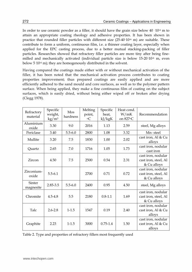
The choice of the refractory filler highly depends on the metal casting temperature. In the foundry technology, fine grinded mineral raw materials are used for coatings; these mineral raw materials are based on olivine, chromite, zircon, siner magnesite, mica, corundum, cordierite and other refractory materials, Table 2.
www.intechopen.com
Ceramic Coatings – Applications in Engineering
272
In order to use ceramic powder as a filler, it should have the grain size below 40 ·10-6 m to attain an appropriate coating rheology and adhesive properties. It has been shown in practice that rounded filler particles with different size (25-40·10-6 m) are suitable. These contribute to form a uniform, continuous film, i.e. a thinner coating layer, especially when applied for the EPC casting process, due to a better mutual stacking-packing of filler particles. Researches showed that refractory filler particles are more tiny after being fine-milled and mechanically activated (individual particle size is below 15-20·10-6 m, even below 5·10-6 m); they are homogenously distributed in the solvent.
Having compared the coatings made either with or without mechanical activation of the filler, it has been noted that the mechanical activation process contributes to coating properties improvement; thus prepared coatings are easily applied and are more efficiently adhered to the sand mould and core surfaces, as well as to the polymer pattern surface. When being applied, they make a fine continuous film of coating on the subject surfaces, which is easily dried, without being either wiped off or broken after drying (Clegg 1978).
Refractory material
Specific weight, kg/m3
Mos hardness
Melting point,
oC
Specific heat,
kJ/kgK
Heat cond.W/mK
on 827oC Recommendation
Aluminium oxide
3.30 9.0 2016 1.13 2.59 steel, Mg alloys
Periclase 3.40 5.5-6.0 2800 1.08 3.32 Mn- steel
Mullite 3.20 7.5 1830 1.00 2.02 cast iron, Al & Cu
alloys
Quartz 2.65 7.0 1716 1.05 1.73 cast iron, nodular
cast iron
Zircon 4.50 7.5 2500 0.54 2.31 cast iron, nodular cast iron, steel, Al
& Cu alloys
Zirconium-oxide
5.5-6.1 2700 0.71 0.72 cast iron, nodular cast iron, steel, Al
& Cu alloys Sinter
magnesite 2.85-3.5 5.5-6.0 2400 0.95 4.50 steel, Mg alloys
Chromite 4.5-4.8 5.5 2180 0.8-1.1 1.69 cast iron, nodular cast iron, steel, Al
& Cu alloys
Talc 2.6-2.8 1-1.5 1547 0.19 2.40 cast iron, nodular cast iron, Al & Cu
alloys
Graphite 2.23 1-1.5 3000 0.75-1.4 1.50 cast iron, nodular cast iron, Al & Cu
alloys
Table 2. Type and properties of refractory fillers most frequently used
www.intechopen.com

Ceramic Coating for Cast House Application
273
6.2 Binding properties
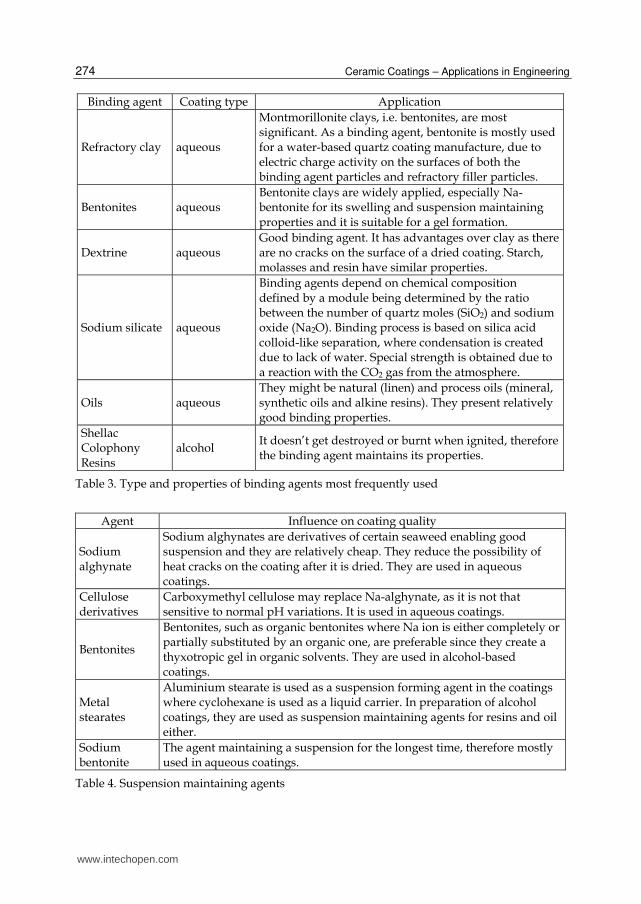
Coating ability to retain its required properties and to be firmly adhered to the subject mould or core surfaces after a liquid component has been dried or expanded is ensured by addition of a binding agent. Binding agent is chosen in accordance with the refractory filler applied, as well as with ability to be dissolved in the liquid carrier of cast house coatings. The quantity of binding agent depends on the particle size of the refractory filler used. It must be carefully chosen, because gas development from the film of coating depends on it, as it is proportional to the excess of binding agent. Binding agents may be organic and non-organic. Depending on the solidification temperature, binding agents are divided into the binding agents being solidified at the room temperature and binding agents being solidified through drying or curing. There are three mechanisms to form the coating hardness: binding agent drying, solidification after binding agent melting and solidification due to chemical processes. With the aqueous coatings containing bentonite, silica esters or water glass, coating solidification is carried out through the loss of a liquid component during heat treatment. With the coatings containing calophonium, bitumen, phurane, formaldehyde, phenol-formaldehyde binding agents and with the sugar-based or glucose-based binding agents, solidification of applied layer is carried out as a result of binding agent solidification after being heated up to its melting temperature. In case that a binding agent polymerisation is carried out or if various components chemically reacts when the applied layer is dried, the molecules of the binding agents are mutually connected into long chains or nets. That’s how a binding agent solidifies. The coatings with a binding agent which is polymerised at the room temperature during a liquid component evapouration are very suitable because they do not require a thermal treatment. The coatings containing this type of binding agent (for example, polyvinilebutirol) easily solidifies once they have been applied on the mould or core surfaces, without heating. Basic requirements for the binding agent quality are the following: thermo-stability, i.e. maximum hardness maintenance at elevated temperatures, during either drying or inflow of liquid metal, in order to prevent coating stratification and crack, minimum gas separation, they must not soak humidity in and alike (Svarika 1977, Tomović 1990). 6.3 Suspension maintaining agent
Suspension maintaining agent keeps the refractory powder particles in a dispersed state. They are divided into two groups: aqueous coating stabilizers and non-aqueous coating stabilizers. These agents prevent precipitation of refractory powder particles and have an important influence on the coating quality. Small amount of carriers causes a quick precipitation of the filler particles and other solid components contained in the coating composition. If there is an excess of carriers, these will cause an increment of coating density causing difficulties for the coating application on the mould or core surfaces; there will also be a crack risk for the thicker coating layers being dried. It is very important that solid matters used for suspension maintenance have the same mass as the liquid coating stage. In that case, suspension is maintained longer, the coating becomes more efficient and metal penetration is prevented. Aqueous coating stabilizers are the following: bentonite, carboxymethylcellulose, alghynate, and polyacrylamide. Alcohol coating stabilizers are the following: polyvinyl-butyral, polysobutylene, organic types of bentonite. Table 4 shows some suspension maintaining agents (Clegg1978, Svarika 1977, Tomović 1990).
www.intechopen.com
Ceramic Coatings – Applications in Engineering
274
Binding agent Coating type Application
Refractory clay aqueous
Montmorillonite clays, i.e. bentonites, are most significant. As a binding agent, bentonite is mostly used for a water-based quartz coating manufacture, due to electric charge activity on the surfaces of both the binding agent particles and refractory filler particles.
Bentonites aqueous Bentonite clays are widely applied, especially Na-bentonite for its swelling and suspension maintaining properties and it is suitable for a gel formation.
Dextrine aqueous Good binding agent. It has advantages over clay as there are no cracks on the surface of a dried coating. Starch, molasses and resin have similar properties.
Sodium silicate aqueous
Binding agents depend on chemical composition defined by a module being determined by the ratio between the number of quartz moles (SiO2) and sodium oxide (Na2O). Binding process is based on silica acid colloid-like separation, where condensation is created due to lack of water. Special strength is obtained due to a reaction with the CO2 gas from the atmosphere.
Oils aqueous They might be natural (linen) and process oils (mineral, synthetic oils and alkine resins). They present relatively good binding properties.
Shellac Colophony Resins
alcohol It doesn’t get destroyed or burnt when ignited, therefore the binding agent maintains its properties.
Table 3. Type and properties of binding agents most frequently used
Agent Influence on coating quality
Sodium alghynate
Sodium alghynates are derivatives of certain seaweed enabling good suspension and they are relatively cheap. They reduce the possibility of heat cracks on the coating after it is dried. They are used in aqueous coatings.
Cellulose derivatives
Carboxymethyl cellulose may replace Na-alghynate, as it is not that sensitive to normal pH variations. It is used in aqueous coatings.
Bentonites
Bentonites, such as organic bentonites where Na ion is either completely or partially substituted by an organic one, are preferable since they create a thyxotropic gel in organic solvents. They are used in alcohol-based coatings.
Metal stearates
Aluminium stearate is used as a suspension forming agent in the coatings where cyclohexane is used as a liquid carrier. In preparation of alcohol coatings, they are used as suspension maintaining agents for resins and oil either.
Sodium bentonite
The agent maintaining a suspension for the longest time, therefore mostly used in aqueous coatings.
Table 4. Suspension maintaining agents
www.intechopen.com

Ceramic Coating for Cast House Application
275
6.4 Liquid carrier or solvent
The role of a liquid carrier or solvent is to dissolve and transport the refractory powder to the sand surface in the form of film. Generally, three types are used: water, alcohol (flammable liquids) and chloric hydrocarbons.
The solvent is chosen depending on several factors, some of which are the following: the type of sand blend, application method, ecological factor, type of production cycle dictating the time allowed for drying and application. Mostly applied solvent is water, for it is the cheapest, but also non-toxic and safe for use. Increment of application costs for this type of coating is due to energy consumption for the coating drying process and for water elimination from the layers applied.
Solvents like alcohol mixtures (methyl, ethyl, isopropyl) with pure water are often flammable liquids. The advantage of alcohol over water is faster drying, which is important for the sand moulds; but, since these coatings are flammable, they require more attention to be paid during production, use and stock-keeping.
Isopropyl-alcohol represents technically most acceptable solvent for the flammable foundry coatings, primarily for its combustion properties being close to perfect. This type of combustion has a reduced erosion risk for the surface observed. Other alcohol solvents are less frequently applied as pure, but mostly together, even when mixed with water (up to 12,0 vol %).
Choloric hydrocarbon is air-dried, eliminating a fire risk when flammable liquids are used. Air-dried coatings are convenient, like flammable liquids: they are self-extinguishable, they have a high steam pressure, they evaporate easily without a usage of heat, but they are also expensive and toxic matters.
7. Recipes
Table 5 shows some recipes of the ceramic coatings used for different casting methods and metal materials for casting production.
8. Application rheology
As far as the effect of ceramic coatings on the quality of the castings obtained is concerned, it is necessary to discuss preparation of the components contained in the coating, coating production and its application rheology which is tightly bound to a proper choice and use of a suitable stabilizer. Generally, it may be defined as follows:
immersion, spraying, pouring, brush application.
Generally, an ideal rheology suitable for coating application by immersion and pouring is an achievement of the properties of pseudoplastic solution, i.e. an achievement of such rheology enabling an instant viscosity drop during application and an immediate viscosity recovery as soon as the coating application stops. On the other hand, the rheology required for coating application by either spraying or brush is an achievement of thixotropic solution, i.e. an achievement of a light viscosity drop during application and a bit faster recovery to the initial
www.intechopen.com

Ceramic Coatings – Applications in Engineering
276
value after application. It practically means that the coating flows well when being applied since recovery to the initial value is not instant, as with pseudo-plastic solutions.
O. No. Content of filler Binding agent, Suspension
maintenance agent
Solvent, density
1,8-2 kg/m3
1. zircon,
with grain size of 40·10-6 m, 86-89%
bentonite 3%; bindal H 7,5%
dextrin 0,3-0,5%, carboxymethyl
cellulose- (CMC), 0,3-0,5%
water
2. mulite,
with grain size of 40·10-6 m, 91%
bentonite 3%; bindal H 5%
dextrin 0,3-0,5%, CMC, 0,3-0,5%
water
3. mica,
with grain size 35-40·10-6 m, 88-90%
bentonite 4%; bindal H 7%
dextrin 0,5%, CMC, 0,5%
water
4.
mica, with grain size
<30·10-6 m, 90 - 94%
bentonite 1,5-2,5%; bindal H 1,3-2%
Na3P3O3 1-3%, carboxymethyl cellulose 0,5%
water
5.
alumina, with grain size 45·10-6
m, 90%
bentonite 3%; Bindal H 6%
dextrin 0,5%, carboxymethyl cellulose 0,5%
water
6.
cordierite, with grain size
<40·10-6 m, 93-95%
colophonium (C20H30O2), 1.2-1.5%;
dextrine 0,5-1%
BentoneSD-3 1.2-1.5%;phenolphormaldehide
resins, 1-1.7 % alcohol
7. chromite,
with grain size 40·10-6
m, 95-96%
phenolphormaldehideresins, 3-3,5%;
Carboxymethyl cellulose 0,3-0,5%
water
8. talc,
with grain size 40·10-6
m, 85%
bentonite 3,5-5%; bindal H 8%
dextrin 0,3-0,5% carboxymethyl
cellulose, 0,3-0,5%
water
9. zircon,
with grain size 40·10-6
m, 98%
bentonite 2%; melasses
(1,4 kg/m3), content 3%
Sulphide alkali (1,30 kg/m3 ), 1,5%
water
10.
chrome-magnesite sand,
with grain size 40-45·10-6 m, 99%
bentonite 1%; melasses (1,4 kg/m3),
content 5-6%
Sulphide alkali (1,30 kg/m3 ), 1%
water
11. olivine,
with grain size 35-40·10-6 m, 85,5-90 %
bentonite 1-1,5%; Dextrin: 1,5-2 % water
Table 5. Composition of various ceramic coatings
www.intechopen.com

Ceramic Coating for Cast House Application
277
When using a coating, it is necessary to mix it constantly (at the speed of 1 rpm) to get a homogenous suspension which, after being applied, provides for an even and uniform coating layer on the surface of mould, core or pattern. Figure 7 shows the influence of suspension mixing process on the applied deposit weight, while Figure 8 shows the influence of suspension mixing on the coating viscosity.
0 40 80 120 160 200 240
6,0
6,4
6,8
7,2
7,6
8,0
8,4constant mixing
non-mixing
Dep
osi
t w
eig
ht,
g
Time, min
Fig. 7. Influence of mixing on the deposit weight (Brome 1988)
4
6
8
10
12
14
16
18
"A"
"B"
Vis
co
sit
y
Mixing grade
"C"
Fig. 8. Influence of mixing extent on the coating viscosity (Brome 1988)
www.intechopen.com

Ceramic Coatings – Applications in Engineering
278
Best results are achieved if certain suspension temperature (usually room temperature) is reached and maintained, apart from suspension stirring when being applied on sand moulds and cores or expendable patterns. Coating suspension temperature influences the quantity of residue and it needs to be constantly controlled (Figure 9). When the temperature rises, coating layer mass drops until certain temperature is reached; afterwards, the mass increases with the temperature growth.
25 30 35
20
22
24
26
28
30
32
34
36
38
Dep
osi
t w
eigh
t, g
Temperature, 0C
21
Fig. 9. Temperature influence on deposit weight (Brome 1988)
50
52
54
56
58
60
62
64
66
68
70
Evap
ora
ted
wa
ter,
%
Time, min
Fig. 10. Influence of drying time on humidity elimination from the coating (Brome 1988)
www.intechopen.com

Ceramic Coating for Cast House Application
279
Coating layers applied must be completely dried either in an oven or in air, Figure10. If the coating is not dry enough, remaining humidity reacts with liquid metal causing porosity defects on castings.
To produce high quality coatings with the properties set in advance, it is necessary to attain a homogenous distribution of refractory filler in the coating suspension. It is also necessary to define the composition of the coating with rheology properties controlled and specially adjusted for a concrete application methods, Figure 11. To attain suspension sedimentation stability, filler particles should be up to 40·10-6 m in size, as it is expected that more tiny filler particles are precipitated slower and that a suspension may homogenize easier and faster. Furthermore, these particles more evenly and fully cover mould and pattern surfaces where the coating is applied. Homogenous coating suspension, Figure11.a, is obtained when the filler particles are rounded and even in size. When larger filler particles are present to a lower extent, with medium grain size of 45·10-6 m, Figure 11.b, it is estimated that the rounded particles with different grain size will also contribute to form a continuous coating layer, due to a better interaction of particles. In case the coating suspension is unevenly stirred during application, coating stratification happens, Figure 11.c (Clegg 1978, Trumbulović 2004).
a. homogenous coating suspension b. coating suspension with larger particles
c. non-homogenous coating suspension (drop-like)
Fig. 11. Microphotos of ceramic coating suspensions
One should bear in mind that homogenous distribution of refractory filler in a suspension depends on suspension preparation during coating application. Especially, an important process parameter is the coating suspension density, mostly within the limits from 1,8-2 kg/m3. In order to attain even coating layers on mould or pattern surfaces during immersion (into a coating suspension tank), the way of eliminating the excess of coating
www.intechopen.com

Ceramic Coatings – Applications in Engineering
280
suspension is important. After immersion, „the cluster“ (representing a number of patterns stacked at the common inflow system, thus prepared for EPC casting process) is taken out of suspension tank, it is kept in a vertical position for 5-10 s in order to decant the excess of suspension; then, it is inclined for 5s in order for the coating to be evenly distributed along the cluster surface, Figure 12.a-c. After being decanted, “the cluster” is ready for a drying process. When applying the coating on sand moulds by either a brush or rag, by either spraying or pouring, coating density has an important role and it should not exceed the value of 2-2.2 kg/m3, Figure 12.d. In this way, dried coating layers do not crack, peel or wipe off, and after casting they are easily taken off the castings surfaces, not requiring the castings to be subsequently cleaned, as shown in Figure 13. It has been established that adhesive forces among the filler particles increase with the filler concentration increment. Under the influence of rheology additives and binding agents, continuous and uniform coating layers might be formed on the treated surfaces. Such coating is easily adhered to the treated mould and pattern surfaces. Dried coating layer thicknesses influence gas permeability and they should be as low as possible; their range is from 0,5-1,5·10-3 m (Clegg 1978, Tomović 1990).
a. coating application by immersion b. taking off the excess of suspension
c. balancing the coating layer on the pattern d. coating application by rag
Fig. 12. Coating application stages
www.intechopen.com

Ceramic Coating for Cast House Application
281
a. sand casting b. EPC casting process
Fig. 13. Taking coating layers easily off the casting surface
9. Control and faults
Quality control for foundry coatings and coating application process control as far as sand moulds and cores and expendable or meltable patterns are concerned is important for production of high quality castings. Establishing the quality of foundry coatings is defined by different standards for this type of refractory products. Standards are used to establish both, foundry classification and quality requirements, as well as technical conditions of application, coating sampling methods, coating test methods and marking of coatings and the way of delivery. Most often, the following coating properties are tested:
application ability, drying behaviour, wipe-off resistance, dry matter amount, precipitation, penetration (Svarika 1977, Tomović 1990).
Assessment of a coating is done according to the following criteria either:
the coating must evenly flow down when being applied, coating layer must not crack or bubble when being dried, coating layer must be easily taken off the castings surface when these are shaken or
cleaned, coating layer must be wipe-off resistant dry matter amount must not vary more than ±2% from the value declared, precipitated matters being precipitated for 24 h may amount to max 5%, coating penetration depth in the mould wall may be in the range from 0,5 to 2 ·10-3 m,
depending on use, solvent and binding agent, coating layer must be permeable to gases, the coating must be compatible with the type and density of polymer pattern, with the
type and size of moulding sand grain and with other EPC process parameters (Svarika 1977, Tomović 1990, Brome 1988).
www.intechopen.com

Ceramic Coatings – Applications in Engineering
282
Table 6 shows typical faults detected on the surface of the coated polystyrene patterns. (Aćimović-Pavlović 2010, Clegg 1978)
Uneven surface of coating layers, with quickly dried thicker coating layers on polymer pattern
Bubbles on the coated surface of polymer pattern, caused by rapidly stirring the coating suspension
during application
Dried ceramic coating layers cracking on the polymer pattern, when the drying is rapid and with thicker
coating layers
Table 6. Typical faults on the polystyrene pattern-coating contact surface
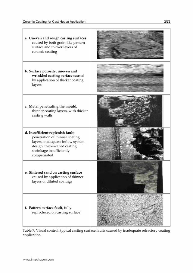
The role of ceramic coatings is to attain a high quality moulding surface. Furthermore, moulding quality is significantly influenced by critical process parameters (casting technology); at first, the choice of material for production of castings, moulds, cores, patterns, ceramic coatings, design faults, i.e. faults concerning pattern construction, inflow system choice and calculation, as well as faults due to disturbance of technological process (human factor). It requires both control and optimization of all process parameters aimed at attainment of the desired structure and utilization properties of castings. Detection, examination and estimate of castings faults should be carried out systematically, at the stage of casting process development and concrete castings production mastering, with an aim to avoid these through preventive measures and to minimize the production costs. Presence of castings faults does not always mean the loss of their utilization value, for it depends on the type, size and position of the fault, as well as on the type of the construction where the castings are installed and on the load character during their exploitation. Therefore, it is necessary to classify the faults with regard to their nature and origin, as well as to the fault outer appearance. This enables the faults to be easily visually detected, estimated and eliminated. Table 7 shows typical moulding surface faults caused by an inadequate ceramic coating application (Acimovic Pavlovic et al., 2007, Cibrik 1977, Svarika 1977, Tsai & Chem, 1988).
www.intechopen.com
Ceramic Coating for Cast House Application
283
a. Uneven and rough casting surfaces caused by both grain-like pattern surface and thicker layers of ceramic coating
b. Surface porosity, uneven and wrinkled casting surface caused by application of thicker coating layers
c. Metal penetrating the mould, thinner coating layers, with thicker casting walls
d. Insufficient replenish fault, penetration of thinner coating layers, inadequate inflow system design, thick-walled casting shrinkage insufficiently compensated
e. Sintered sand on casting surface caused by application of thinner layers of diluted coatings
f. Pattern surface fault, fully reproduced on casting surface
Table 7. Visual control: typical casting surface faults caused by inadequate refractory coating application.
www.intechopen.com

Ceramic Coatings – Applications in Engineering
284
For a detailed analysis of structural and mechanical casting characteristics after a visual examination, it is necessary to apply some other test methods either. Casting test without destruction may reveal the presence of volume faults in the casting. Microstructural tests of castings point to the influence of individual process parameters on the casting cooling and solidification in a mould. Figure 14 shows some faults in the casting structure caused by application of an inadequate ceramic coating in the casting process.
a. casting with no porosity
b. casting with classified porosity
c. intensive porosity over the volume, higher pattern density and thicker coating layers, EPC
process
Fig. 14. Casting faults detected by radiographic method
www.intechopen.com

Ceramic Coating for Cast House Application
285
10. Conclusion
Utilization of ceramic coatings with different types of fillers (talc-based, cordierite-based, zircon-based, mulite-based, mica-based, chromite – based and alike) in casting decisively depends on rheology coating properties, i.e. on sedimentation suspension stability. It is necessary to carry out researches referring to optimized coating properties and to their production procedures aimed to obtain the coating properties required. Coating application in practice shows positive effects regarding high quality castings, satisfactory structure and properties, shiny and smooth castings surfaces, with no surface or volume faults whatsoever.
11. References
Aćimović Z., Tomović M., Đuričić M. & Tomović S. (1994) Litejnoje proizvodstvo, Vol. 12, ISSN 0024-449x , p.19
Aćimović Z., Pavlović Lj., Trumbulović Lj., Andrić Lj. & Stamatović M. (2003) Synthesis and Caracterization of the Cordierite Ceramics from Non-Standard Raw Materials for Application in Foundry. Materials Letters. Vol. 57, No 18, ISSN 0167-577X, pp. (2651-2656).
Aćimović-Pavlović Z., Prstić A. & Andrić Lj. (2007) The characterization of talc-based coating for application for Al-Si alloy casting. CI&CEQ. Vol.13, No 1, ISSN 1451-9372,pp. (40-48).
Aćimović-Pavlović Z., Đuričić M., Drmanić S., Đuričić R, (2010) The influence of the parameters of Lost foam process on the quality of the aluminium alloys castings, Chemical Industry. Vol.64, No.2, ISSN 0367-598X, pp. (121-127).
Aćimović-Pavlović Z., Andrić Lj., Milošević V., & Milićević S. (2011) Refractory coating based on cordierite for application in new evaporate pattern casting process. Ceramic International. Vol.37, No.1, ISSN 0272-8842,pp. (99-104).
Ballman R. (1988) Assembly and coating of polystyrene foam patterns for the Evaporate Pattern Casting Process, Proceedings of 92nd Casting Congress, Hartford, Connecticut, USA, 1988,pp. 250.
Brome A.J. (1988) Mould and core coatings and their application. British Foundrymen. Vol. 80 No.4, pp.( 342-350), ISSN 0007-0718.
Burditt M. (1988) EPCs Promise Belies Complex Process, Modern Casting. Vol 8 , August 1988, ISSN 0026-7562,pp.(20-24).
Cho N. D. (1989) Effect of coating materials on fluidity and temperature loss of molten metals in full mould, Proceedings of 56th World Foundry Congress, Düsseldorf, Germany, No 7.1.7.10.
Cibrik A.N. (1977) Fizičko-hemičeskije procesi v kontaktnoj zone metal-forma, Nauka Dumka Kiev.
Clegg A. (1978) The Full-Mould Process-A Review, Part II: Production of Castings, Foundry Trade Journal, Vol. 3, No. 8, ISSN 0015-9042,pp.(383-398).
Davies R.W. (1996) The replacement of solvent based coatings in modern foundries, Foundrymen, Vol. 89, No. 9, ISSN 0953-6035, pp.(287-290).
Gorny Z. & Marcinkowski J.(1977) New ideas in investigating and evaluating the sand and core materials, Transaction. pp.(893-910).
www.intechopen.com

Ceramic Coatings – Applications in Engineering
286
Josipović Ž., Marković S.,Aćimović Z. & Tomović S. (1994) Foundry linings-present state. Journal of foundry XLII, Vol. 94, pp.(17-20).
Monroe R. (1994) Expandable Pattern Casting, AFS, USA. Shivukumar S., Wang L. & Steenhoft B.: Phisico-Chemical aspect of the Full mould casting
of aluminium alloys, part I: The Degradation of Polystyrene. Transaction. Vol. 95, pp.(791-800).
Svarika A.A.(1977) Pokritia litejnih form, Mašinostroenije,Moskva. Tomović M.N.(1990) Casting of non-ferrous aloys, Faculty of Technology and Metallurgy
University of Belgrade, Belgrade, Serbia Trumbulović Lj., Aćimović Z., Gulišija Z. & Andrić Lj. (2004) Correlation of Technological
Parameters and Quality of Castings Obtained by the EPC Method. Materials Letters. Vol. 58, No. 11, ISSN 0167-577X , pp.(1726-1731).
Tsai H. & Chem T.S. (1988) Modelling of Evaporative Pattern process, Part I, Metal Flow and Heat Transfer During the Fillings Stage. Proceedings of 92nd Casting Congress, Hartford, Connecticut, USA, pp. 300,
www.intechopen.com

Ceramic Coatings - Applications in EngineeringEdited by Prof. Feng Shi
ISBN 978-953-51-0083-6Hard cover, 286 pagesPublisher InTechPublished online 24, February, 2012Published in print edition February, 2012
InTech EuropeUniversity Campus STeP Ri Slavka Krautzeka 83/A 51000 Rijeka, Croatia Phone: +385 (51) 770 447 Fax: +385 (51) 686 166www.intechopen.com
InTech ChinaUnit 405, Office Block, Hotel Equatorial Shanghai No.65, Yan An Road (West), Shanghai, 200040, China
Phone: +86-21-62489820 Fax: +86-21-62489821
The main target of this book is to state the latest advancement in ceramic coatings technology in variousindustrial fields. The book includes topics related to the applications of ceramic coating covers in enginnering,including fabrication route (electrophoretic deposition and physical deposition) and applications in turbineparts, internal combustion engine, pigment, foundry, etc.
How to referenceIn order to correctly reference this scholarly work, feel free to copy and paste the following:
Zagorka Aćimović-Pavlović, Aurel Prstić, Ljubiša Andrić, Vladan Milošević and Sonja Milićević (2012). CeramicCoating for Cast House Application, Ceramic Coatings - Applications in Engineering, Prof. Feng Shi (Ed.),ISBN: 978-953-51-0083-6, InTech, Available from: http://www.intechopen.com/books/ceramic-coatings-applications-in-engineering/ceramic-coatings-for-application-in-foundry

© 2012 The Author(s). Licensee IntechOpen. This is an open access articledistributed under the terms of the Creative Commons Attribution 3.0License, which permits unrestricted use, distribution, and reproduction inany medium, provided the original work is properly cited.