certification by analysis of aircraft seats - home : faa … · 2011-01-14 · certification by...
TRANSCRIPT
N A T I O N A L I N S T I T U T E F O R A V I A T I O N R E S E A R C H
Certification by Analysis of Aircraft Seats
Gerardo Olivares
6th Triennial International Aircraft Fire and Cabin Safety Research Conference
October 25‐28 2010

N A T I O N A L I N S T I T U T E F O R A V I A T I O N R E S E A R C H
AC 20‐146 ‐ Scope• This document defines the acceptable applications, limitations, validation
processes, and minimum documentation requirements involved when substantiation by computer modeling is used to support a seat certification program.
• Computer modeling analytical techniques may be used to do the following, provided all pass/fail criteria identified in §§ 23.562, 25.562, 27.562, or 29.562 are satisfied:– Establish the critical seat installation/configuration in preparation for dynamic
testing.
– Demonstrate compliance to §§ 23.562, 25.562, 27.562, or 29.562 for changes to a baseline seat design, where the baseline seat design has demonstrated compliance to these rules by dynamic tests. Changes may include geometric or material changes to primary and non‐primary structure.
2
N A T I O N A L I N S T I T U T E F O R A V I A T I O N R E S E A R C H
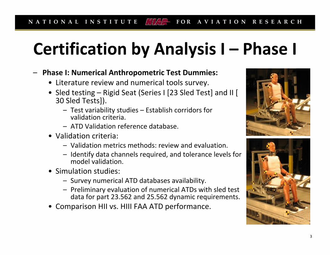
Certification by Analysis I – Phase I– Phase I: Numerical Anthropometric Test Dummies:
• Literature review and numerical tools survey.• Sled testing – Rigid Seat (Series I [23 Sled Test] and II [ 30 Sled Tests]).– Test variability studies – Establish corridors for validation criteria.
– ATD Validation reference database.• Validation criteria:
– Validation metrics methods: review and evaluation.– Identify data channels required, and tolerance levels for model validation.
• Simulation studies:– Survey numerical ATD databases availability.– Preliminary evaluation of numerical ATDs with sled test data for part 23.562 and 25.562 dynamic requirements.
• Comparison HII vs. HIII FAA ATD performance.
3
N A T I O N A L I N S T I T U T E F O R A V I A T I O N R E S E A R C H
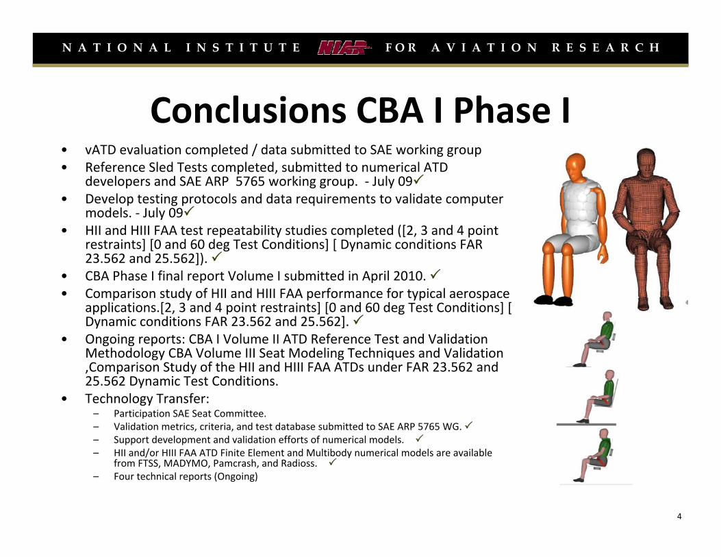
Conclusions CBA I Phase I• vATD evaluation completed / data submitted to SAE working group• Reference Sled Tests completed, submitted to numerical ATD
developers and SAE ARP 5765 working group. ‐ July 09• Develop testing protocols and data requirements to validate computer
models. ‐ July 09• HII and HIII FAA test repeatability studies completed ([2, 3 and 4 point
restraints] [0 and 60 deg Test Conditions] [ Dynamic conditions FAR 23.562 and 25.562]).
• CBA Phase I final report Volume I submitted in April 2010. • Comparison study of HII and HIII FAA performance for typical aerospace
applications.[2, 3 and 4 point restraints] [0 and 60 deg Test Conditions] [ Dynamic conditions FAR 23.562 and 25.562].
• Ongoing reports: CBA I Volume II ATD Reference Test and Validation Methodology CBA Volume III Seat Modeling Techniques and Validation ,Comparison Study of the HII and HIII FAA ATDs under FAR 23.562 and 25.562 Dynamic Test Conditions.
• Technology Transfer:– Participation SAE Seat Committee.– Validation metrics, criteria, and test database submitted to SAE ARP 5765 WG. – Support development and validation efforts of numerical models.– HII and/or HIII FAA ATD Finite Element and Multibody numerical models are available
from FTSS, MADYMO, Pamcrash, and Radioss.– Four technical reports (Ongoing)
4
N A T I O N A L I N S T I T U T E F O R A V I A T I O N R E S E A R C H
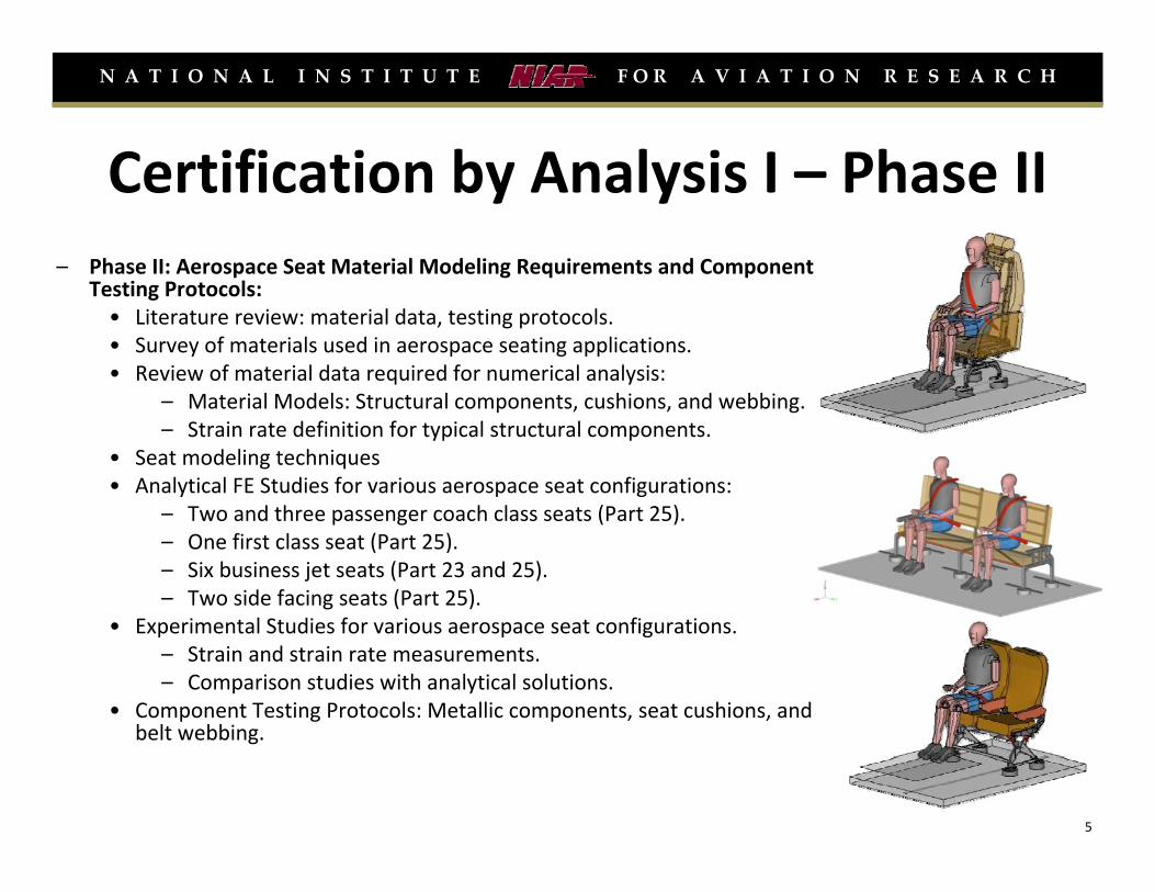
Certification by Analysis I – Phase II– Phase II: Aerospace Seat Material Modeling Requirements and Component
Testing Protocols:• Literature review: material data, testing protocols.• Survey of materials used in aerospace seating applications.• Review of material data required for numerical analysis:
– Material Models: Structural components, cushions, and webbing.– Strain rate definition for typical structural components.
• Seat modeling techniques• Analytical FE Studies for various aerospace seat configurations:
– Two and three passenger coach class seats (Part 25).– One first class seat (Part 25).– Six business jet seats (Part 23 and 25).– Two side facing seats (Part 25).
• Experimental Studies for various aerospace seat configurations.– Strain and strain rate measurements.– Comparison studies with analytical solutions.
• Component Testing Protocols: Metallic components, seat cushions, and belt webbing.
5
N A T I O N A L I N S T I T U T E F O R A V I A T I O N R E S E A R C H
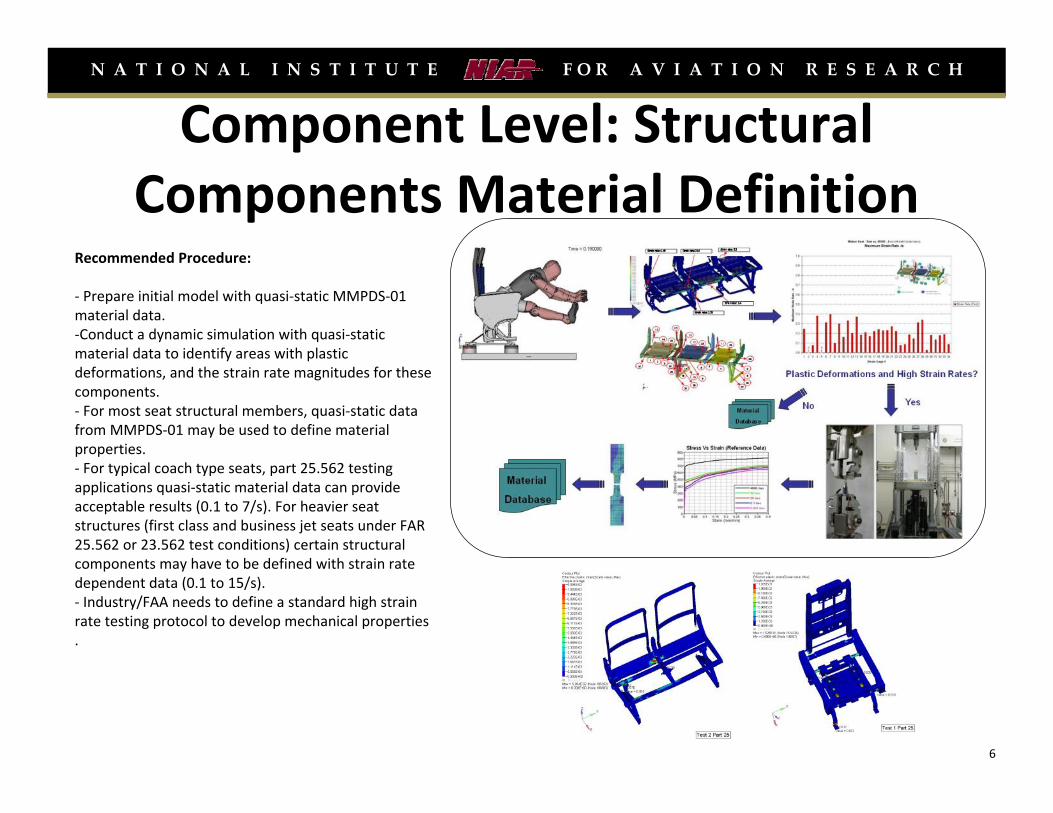
Component Level: Structural Components Material Definition
Recommended Procedure:
‐ Prepare initial model with quasi‐static MMPDS‐01 material data.‐Conduct a dynamic simulation with quasi‐static material data to identify areas with plastic deformations, and the strain rate magnitudes for these components.‐ For most seat structural members, quasi‐static data from MMPDS‐01 may be used to define material properties.‐ For typical coach type seats, part 25.562 testing applications quasi‐static material data can provide acceptable results (0.1 to 7/s). For heavier seat structures (first class and business jet seats under FAR 25.562 or 23.562 test conditions) certain structural components may have to be defined with strain rate dependent data (0.1 to 15/s).‐ Industry/FAA needs to define a standard high strain rate testing protocol to develop mechanical properties .
6
N A T I O N A L I N S T I T U T E F O R A V I A T I O N R E S E A R C H
N A T I O N A L I N S T I T U T E F O R A V I A T I O N R E S E A R C H
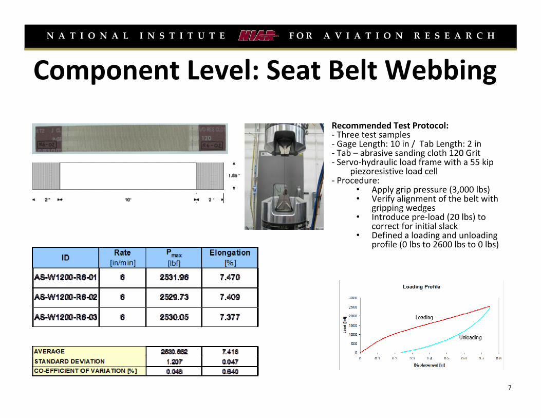
Component Level: Seat Belt Webbing
Recommended Test Protocol: ‐ Three test samples‐ Gage Length: 10 in / Tab Length: 2 in‐ Tab – abrasive sanding cloth 120 Grit‐ Servo‐hydraulic load frame with a 55 kip
piezoresistive load cell‐ Procedure:
• Apply grip pressure (3,000 lbs)• Verify alignment of the belt with
gripping wedges• Introduce pre‐load (20 lbs) to
correct for initial slack• Defined a loading and unloading
profile (0 lbs to 2600 lbs to 0 lbs)
N A T I O N A L I N S T I T U T E F O R A V I A T I O N R E S E A R C H
7
N A T I O N A L I N S T I T U T E F O R A V I A T I O N R E S E A R C H
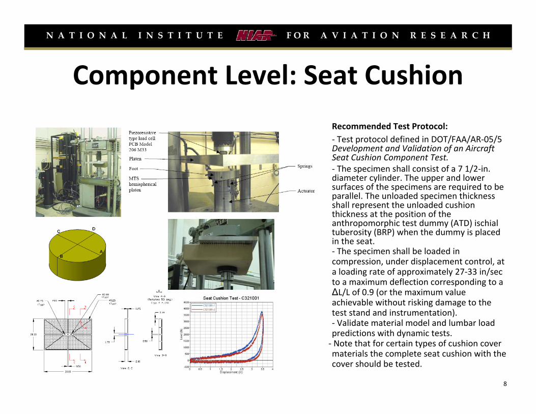
Component Level: Seat Cushion
Recommended Test Protocol: ‐ Test protocol defined in DOT/FAA/AR‐05/5 Development and Validation of an Aircraft Seat Cushion Component Test.‐ The specimen shall consist of a 7 1/2‐in. diameter cylinder. The upper and lower surfaces of the specimens are required to be parallel. The unloaded specimen thickness shall represent the unloaded cushion thickness at the position of the anthropomorphic test dummy (ATD) ischial tuberosity (BRP) when the dummy is placed in the seat. ‐ The specimen shall be loaded in compression, under displacement control, at a loading rate of approximately 27‐33 in/sec to a maximum deflection corresponding to a ΔL/L of 0.9 (or the maximum value achievable without risking damage to the test stand and instrumentation).‐ Validate material model and lumbar load predictions with dynamic tests.‐ Note that for certain types of cushion cover materials the complete seat cushion with the cover should be tested.
N A T I O N A L I N S T I T U T E F O R A V I A T I O N R E S E A R C H
8

N A T I O N A L I N S T I T U T E F O R A V I A T I O N R E S E A R C H
Seat Modeling Process ‐ CAE3D CAD MODEL GEOMETRY DEFEATURE
GEOMETRY DISCRETIZATION EIGENVALUE ASSEMBLY CHECK
NUMERICAL MODEL DEFINITION OCCUPANT & BELT POSITION
DYNAMIC EVALUATION
1
2
3
4
5
6
7
9
N A T I O N A L I N S T I T U T E F O R A V I A T I O N R E S E A R C H
N A T I O N A L I N S T I T U T E F O R A V I A T I O N R E S E A R C H
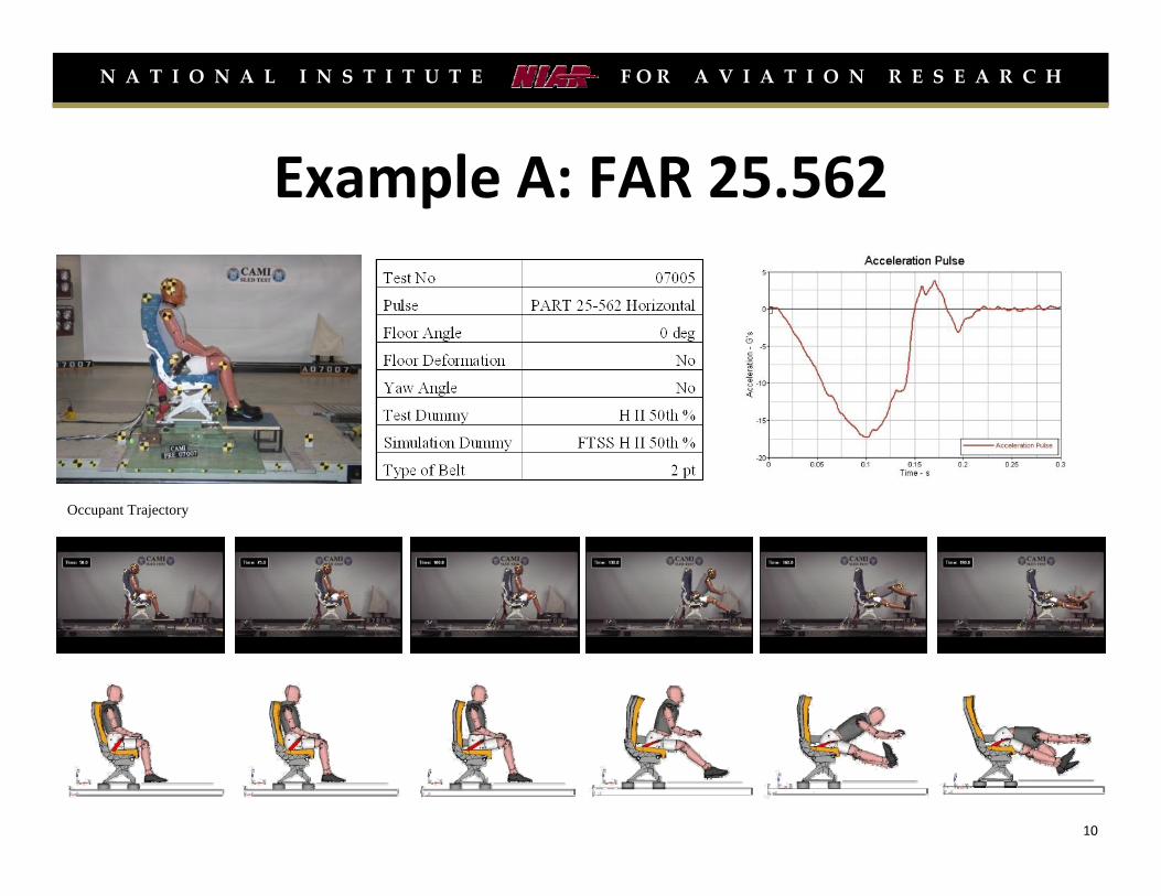
Example A: FAR 25.562
Occupant Trajectory
10
N A T I O N A L I N S T I T U T E F O R A V I A T I O N R E S E A R C H
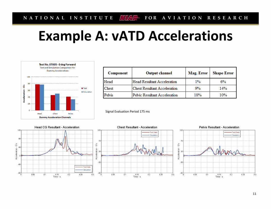
Example A: vATD Accelerations
Signal Evaluation Period 175 ms
11
N A T I O N A L I N S T I T U T E F O R A V I A T I O N R E S E A R C H
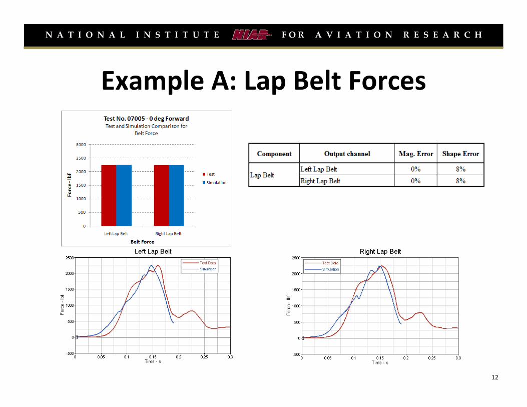
Example A: Lap Belt Forces
12
N A T I O N A L I N S T I T U T E F O R A V I A T I O N R E S E A R C H
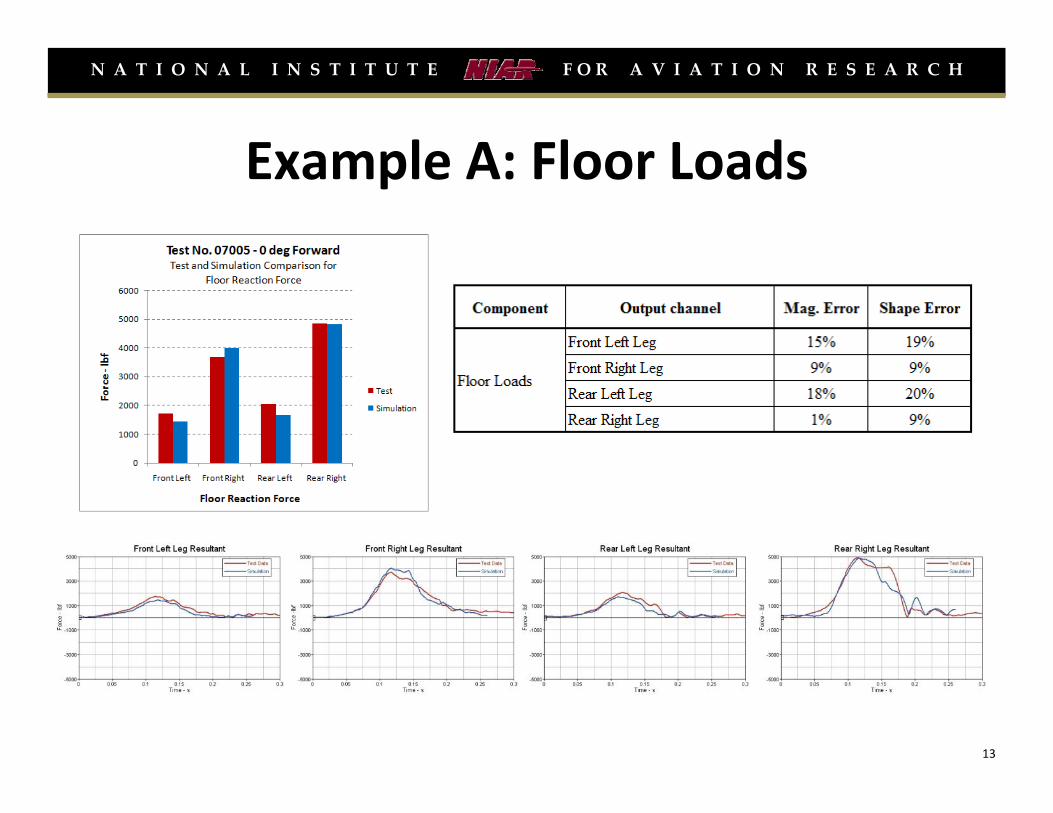
Example A: Floor Loads
13

N A T I O N A L I N S T I T U T E F O R A V I A T I O N R E S E A R C H
Example B: FAR 25.562
Occupant Trajectory
14
N A T I O N A L I N S T I T U T E F O R A V I A T I O N R E S E A R C H
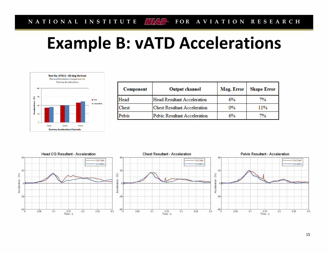
Example B: vATD Accelerations
15
N A T I O N A L I N S T I T U T E F O R A V I A T I O N R E S E A R C H
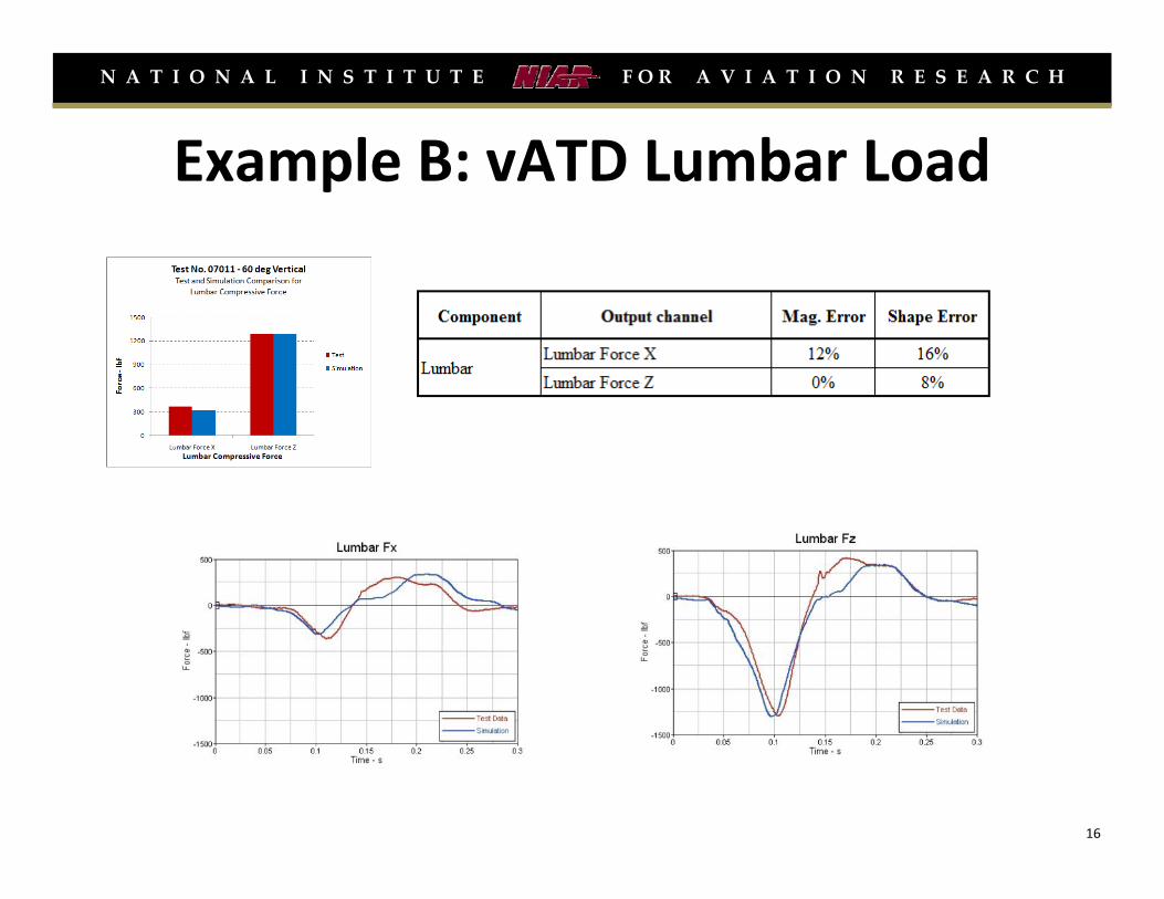
Example B: vATD Lumbar Load
16

N A T I O N A L I N S T I T U T E F O R A V I A T I O N R E S E A R C H
Example C: Rigid Bulkhead Installation
17

N A T I O N A L I N S T I T U T E F O R A V I A T I O N R E S E A R C H
Example C: Kinematic Frames
18

N A T I O N A L I N S T I T U T E F O R A V I A T I O N R E S E A R C H
Example C: Kinematic Frames
19
N A T I O N A L I N S T I T U T E F O R A V I A T I O N R E S E A R C H
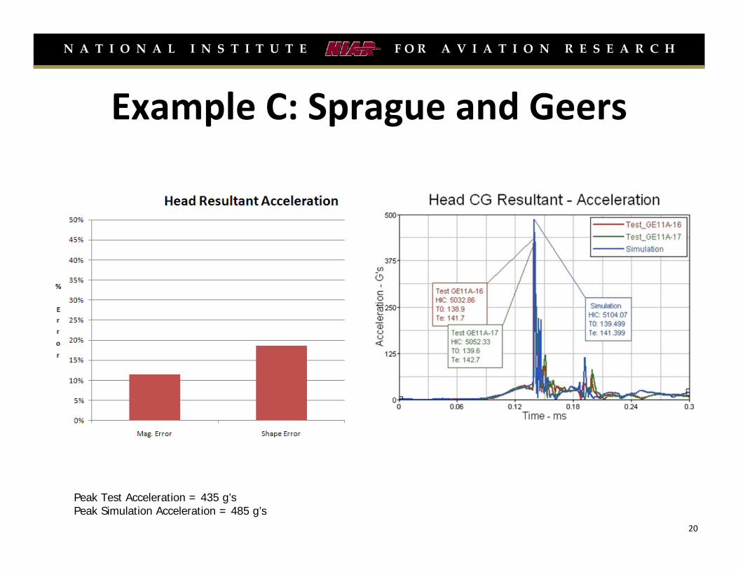
Example C: Sprague and Geers
Peak Test Acceleration = 435 g’sPeak Simulation Acceleration = 485 g’s
20
N A T I O N A L I N S T I T U T E F O R A V I A T I O N R E S E A R C H
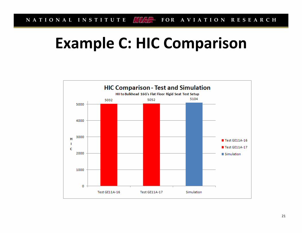
Example C: HIC Comparison
21
N A T I O N A L I N S T I T U T E F O R A V I A T I O N R E S E A R C H
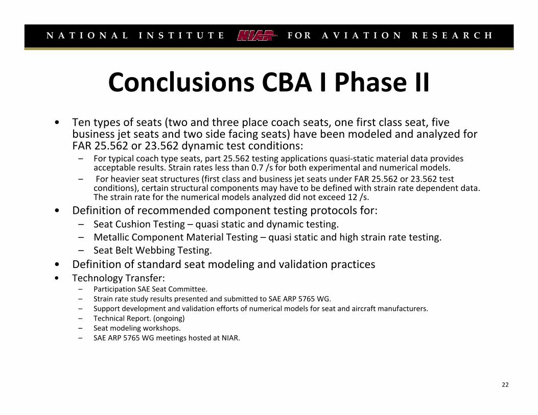
Conclusions CBA I Phase II• Ten types of seats (two and three place coach seats, one first class seat, five
business jet seats and two side facing seats) have been modeled and analyzed for FAR 25.562 or 23.562 dynamic test conditions:– For typical coach type seats, part 25.562 testing applications quasi‐static material data provides
acceptable results. Strain rates less than 0.7 /s for both experimental and numerical models. – For heavier seat structures (first class and business jet seats under FAR 25.562 or 23.562 test
conditions), certain structural components may have to be defined with strain rate dependent data. The strain rate for the numerical models analyzed did not exceed 12 /s.
• Definition of recommended component testing protocols for:– Seat Cushion Testing – quasi static and dynamic testing. – Metallic Component Material Testing – quasi static and high strain rate testing.– Seat Belt Webbing Testing.
• Definition of standard seat modeling and validation practices• Technology Transfer:
– Participation SAE Seat Committee.– Strain rate study results presented and submitted to SAE ARP 5765 WG. – Support development and validation efforts of numerical models for seat and aircraft manufacturers.– Technical Report. (ongoing) – Seat modeling workshops.– SAE ARP 5765 WG meetings hosted at NIAR.
22

N A T I O N A L I N S T I T U T E F O R A V I A T I O N R E S E A R C H
Future Research: Structural Crashworthiness
Phase I: Airframe Crashworthiness Evaluation* by Analysis [July 2009 –September 2011]:
– Evaluation coupon level material testing variability – Composites (Fiberglass, Toray‐Carbon Uni, Toray Carbon Fabric ) and Metallic Materials (Al 7075‐T6)
– Coupon Level Material Model Validation – Composites and Metallic Materials
– Literature review NTSB aircraft crash data
– Develop an energy based analytical method to define stiffness, crush zone, and deceleration profiles
– Metallic airframe preliminary crashworthiness evaluation – Hard Surfaces, Soft Soil and Water Impact
– Propose Airframe Crashworthiness Evaluation Methodology
* Note there are no current requirements for airframe crashworthiness, only special conditions with the introduction of composite fuselages (equivalent level of safety to metallic structures).
23

N A T I O N A L I N S T I T U T E F O R A V I A T I O N R E S E A R C H
Contact Information
Gerardo Olivares
Email: [email protected]
National Institute for Aviation Research
1845 Fairmount
Wichita, KS 67208