certified copy of order - showmeboone.com · certified copy of order ... will this proposal have on...
TRANSCRIPT

CERTIFIED COPY OF ORDER
STATE OF MISSOURI ) May Session of the April Adjourned Term. 20 09 ea.
County of Boone
In the County Commission of said county, on the 19th day of May 20 09
the following, among other proceedings, were had, viz:
Now on this day the County Commission of the County of Boone does hereby authorize the transfer of Roy Lindsey to Position No. 164-Cook Supervisor at 1 1 1 % of Mid-Point.
Done this 19th day of May, 2009.
~ e h e t hM. Pearson Presiding Commissioner
ATTEST: s r-4-Karen M. Miller
Wendy S. N en District n
I Commissioner Clerk of the County Commission

REQUEST TO TRANSFER ABOVE "ATS" (Authorized Transfer Salary) BOONE COUNTY Commission Order 146-2006 RFE!WEF
Descri~tion of form: To request approval to transfer above "ATS" (authorized transfer salary). Procedure: . The Administrative Authority or desimee completes the form and prepares a schedule that demonstrates that funding is a v a i l a w t h k t k 2009
salary and wage appropriation (account #10100) and calculates the'kount for a budget revision, if needed. The ~dhinistrative Authority submits the form, the schedule, and the budget revision (if needed) to the Auditor for certification of funds availability. BOONE COUNnAUD~
2. The Auditor certifies funds availability, approves budget revision (if applicable), returns original form to the Administrative Authority and forwards a c o ~ v .- to Human Resource Director.
3. The Human Resource Director reviews the request and provides recommendation to the Administrative Authority. 4. The Administrative Authority will schedule the request for approval by the Commission and provide the Commission with the HR Director's
recommendation. The County Commission will review all requests for a starting salary above the "ATS" and will either approve or deny the request. After approvalldenial, the County Commission will return this form to the Administrative Authority.
will attach a copy of this approved form to the Personnel Action Form.
Name of prospective employeeRoy Lindsey Department Boone County Sheriffs D e ~ t .
Position Title-Cook Supervisor Position N o . 1 6 4
Proposed Starting Salary (complete one only) Annual: % of Mid-Point OR Hourly: $ 1 9 . 0 3 % of Mid-Point 1 1 1
No. of employees in this job classification within your D e p a r t m e n t ? l Justification (Describe the prospective employee's education andlor work experience which supports this proposed compensation level) Roy has been employed with the Boone County since 1986 and with the Sheriffs Department since February 1988. Roy has been a part of the kitchen staff since the beginning of his employment. He has extensive experience with the equipment, staff. and inmate trustee's that will now be under his supervision. Roy has served as the interim director several times in the last 2 1 years and has filled this roll in an exemplary manner. Roy will remain a valuable asset to the corrections division in his new position as Cook Supervisor.
If proposed salary exceeds what other employees in the same job classification are paid, explain how the prospective employee's hackground exceeds others working in the same job classification: Roy salary will be $1.6 1 less than the previous Cook Supervisor.
here are no other employees in this classification.
What effect, if any, will this proposal have on salary relationships with other positions in your office andlor positions in other offices? This should not affect any other employee. Roy has been with our department longer than any other cook and is the only cook to have served as interim cook supervisor.
Additional comments: Roy will be an asset to the corrections division and will bring knowledge and inmate rapport not found in other candidates. A
Administrative Authority's Signature: Date: /C/- d 9 I
Auditor's Certification: J Funds are available within the existing depart ental salary and wage appropriation (#10100). Funds are not available within the existing de fartmental salary and wage appropriation (#10100);
Auditor's Signature: n required to provide funding is attached.
Date: shg/O?
QILL R a k aP~ODIT-Ia-0-(N F,,LUUL C I - = P %3GO -+ ~elatdp y m l l Sdle ? bcgk Human Resource Director's Recommendations:
I
Human Resource Director's Signature:
County Commission ,d Approve Deny Comment(s): I
District I Commissioner's Signature:

I 11255 CLASS 1 SALARY & WAGES I
AMOUNT BUDGETED $1,932,858 00 PER QTR $ 483,214 50 I
I I
1ST QTR OVERIUNDER I
USED -110 112009 RVS I A 2009 $19 (58,900 10) 1 I0912009 PAYROLL 11912009 P I 2009 1 $ 73,625 12 1 I2312009 PAYROLL 112312009 P 2009 34 $ 72,877 00 2/06/2009 PAYROLL 2/6/2009 P 2009 4 9 ' 8 80,01189 212012009 PAYROLL 212012009 P 2009 72 $ 79,751 28 3/06/2009 PAYROLL 3/6/2009 P 2009 8 7 $ 79,21276 312012009 PAYROLL 3/20/2009 P 2009 $102 77,086 51 3/31 I2009 QTR A 2009 222 $ (59,075 00) I
TOTAL QTR # I $ 344,58946 $ 138,625 04
I I

CERTIFIED COPY OF ORDER
STATE OF MISSOURI } May Session of the April Adjourned Term. 20 09 ea.
County of Boone
In the County Commission of said county, on the 1 9th day of May 20 09
the following, among other proceedings, were had, viz:
Now on this day the County Commission of the County of Boone does hereby approve the following budget amendment for the purchase of a K9:
Department Account Department Name Account Name Decrease Increase 2550 92300 Sheriff Revolving Fund Rep1 Mach. & Equip. $1 1,500.00 2550 59000 Sheriff Revolving Fund Gasoline $650.00 2550 37230 Sheriff Revolving Fund Meals & Lodging $5,560.00 2550 23850 Sheriff Revolving Fund Minor Equip & Tools $1,000.00
Done this 1 9th day of May, 2009.
~ e n h e t hM. Pearson Presiding Commissioner
ATTEST:
District I Commissioner Clerk of the County Commission
District I1 ~o'mmissioner

CERTIFIED COPY OF ORDER
STATE OF MISSOURI May Session of the April Adjourned Term. 20 O9) ea. County of Boone
In the County Commission of said county, on the 1 9th day of May 20 O9
the following, among other proceedings, were had, viz:
Now on this day the County Commission of the County of Boone does hereby approve Amendment Number One -20-06MAY08 -Metal Culvert Pipe with Metal Culverts, Inc. It is further ordered the Presiding Commissioner is hereby authorized to sign said amendment.
Done this 19'" day of May, 2009.
~ e r k e t hM. Pearson Presiding Commissioner
ATTEST:
en M. Miller D i s t r i ~ o m r n i s s i o n e r
Clerk of the County Commission
Skip Elkin \District I1 Commissioner
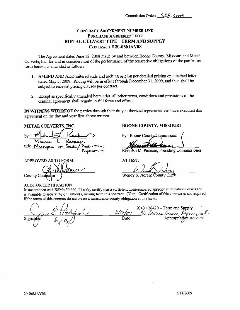
Commission Order: 2 i?-,5-2~07
CONTRACTAMENDMENT NUMBER ONE PURCHASE FORAGREEMENT
METAL CULVERT PIPE -TERM AND SUPPLY CONTRACT# 20-06MAY08
The Agreement dated June 12,2008 made by and between Boone County, Missouri and Metal Culverts, Inc. for and in consideration of the performance of the respective obligations of the parties set forth herein, is amended as follows:
1. AMEND AND ADD mitered ends and arching pricing per detailed pricing on attached letter dated May 5,2009. Pricing will be in effect through December 3 1,2009, and then shall be subject to renewal pricing clauses per contract.
2. Except as specifically amended hereunder, all other terms, conditions and provisions of the original agreement shall remain in full force and effect.
IN WITNESS WHEREOF the parties through their duly authorized representatives have executed this agreement on the day and year first above written.
METAL CULVERTS. INC. BOONE COUNTY, MISSOURI
by 4,J L - A x 7 L WWA- L-CiZAc(LCPr;
title MW- bF / ' ~ . k r i ~ u ~ ~ d I l W~b'7'Fq
ATTEST:
Wendy S. ~o ren@ount~ ~ l d k
AUDITOR CERTIFICATION In accordance with RSMo 50.660, I hereby certify that a sufficient unencumbered appropriation balance exists and is available to satisfy the obligation(s) arising fi-om this contract. (Note: Certification of this contract is not required if the terms of this contract do not create a measurable county obligation at this time.)

METAL CULVERTS INC PAGE 01/01 P. 01/01
Boone County-Purchasing Mehda Bobbitt, CPPB 601 E.Walnut St., Roam 205 Director Columbia, MO 65201
Phone: (573) 886-4391 Fax: (573) 886-4390
May 5?2009
Greg Bwmcr Mttnl Culvens, lac. POBox 330 Jcffkraon City, MO 65102m0330
RE:20-06MAYOB - Metal Culvert fipe -Tenamd Supply
Dear Mr. Bauner:
Pl- provide a quote forpricing for miteredurds and arcbhg. rf accccepce8, this prlchg will be good for theperiod July 1, 2009 tbrou* Decerakm 31,2809 aad will bc added to contract20-06MAYOS -Metal Culvtrr:Pipe --Team and SuppIy.
Archinn fee Zbr unepedfled arch size^: Add 9 -%per base bid price ofroundpipe and bands.
Mitered ends:
Should you havm any quadons or need additionalinfwmation, J may bc raachcd ~t(573) 8864391 or by w a i l to; m h o b b @ , b b ~ e c . m t ~ .Plelue returnrhis quote by fax to (573) 886-4390,
Melinda Bobbitt, CPPB Director ofPurchasiug
cc: BidFile Chip EsFebroafie,PW
CERTIFIED COPY OF ORDER
STATE OF MISSOURI } May Session of the April Adjourned Term. 20 09 ea.
County of Boone
In the County Commission of said county, on the 1 9th day of M ~ Y 20 09
the following, among other proceedings, were had, viz:
Now on this day the County Commission of the County of Boone does hereby award bid 23- 14APR09 - Sheriffs Department Emergency Equipment Term and Supply to Ka-Comm Inc., and Express Police Supply. It is further ordered the Presiding Commissioner is hereby authorized to sign said contracts.
Done this 1 9th day of May, 2009.
Presiding Commissioner ATTEST:
A-
Karen M. Miller -Wendy S. No en D i s t r ~ c o m m i s s i o n e r Clerk of the County Commission
Skip ~lkitE\ District I1 Commissioner

Commission Order # LILb- l m q
PURCHASE AGREEMENT FOR
Sheriffs Department Emergency Equipment Term and Supply
THIS AGREEMENT dated the / qfk day of 2009 is made between Boone &4JCounty, Missouri, a political subdivision of the State of Missouri thro gh the Boone County Commission, herein
"County" and Express Police Supply. herein "Contractor".
IN CONSlDERATION of the parties performance of the respective obligations contained herein, the parties agree as follows:
1. Contract Documents - This agreement shall consist of this Purchase Agreement for Sheriffs Department Emergency Equipment Term and Supply, County of Boone Request for Bid number 23-14APR09, Introduction and General Conditions of Bidding, Primary Specifications, Response Presentation and Review, the un-executed Response Form, Standard Terms and Conditions, any applicable addenda, as well as the Contractor's bid response dated April 02,2009 and executed by Jim Margaret Crane, on behalf of the Contractor. All such documents shall constitute the contract documents, which are attached hereto and incorporated herein by reference. Service or product data, specification and literature submitted with bid response may be permanently maintained in the County Purchasing Office bid file for this bid if not attached. In the event of conflict between any of the foregoing documents, the Introduction and General Conditions of Bidding, Primary Specifications, Response Presentation and Review, the un-executed Response Form, Standard Terms and Conditions, and any applicable addenda shall prevail and control over the Contractor's bid response.
2. Contract Duration - This agreement shall commence on the date of award and extend through June 30, 2010 subject to the provisions for termination specified below. This agreement may be extended beyond the expiration date by the order of the county for three (3) additional one (1) year periods subject to the pricing clauses in the contractor's RFB response and thereafter on a month to month basis in the event the County is unable to re-bid and/or award a new contract prior to the expiration date after exercising diligent efforts to do so or not.
3. Purchase - The County agrees to purchase ftom the Contractor and the Contractor agrees to supply the County with the following items per the bid specifications and responded to on the Response Form:
4.7.2.1. Super - LED Interior Light Bar -Inner Edge Front 4.7.2.2. Super -LED Interior Light Bar 0 Inner Edge Rear 4.7.2.3.2009 Dodge Charger Interface Module 4.7.2.4. Super -LED Dodge Charger Fog Light Mount Light Head 4.7.2.5.LINZ6 Warning Lights 4.7.2.6. LED Lamp Driver 4.7.2.7. Remote Concealed Super -LED Heads 4.7.2.8. Siren Amplifier, Control Head, and Arnplifier/Relay Module 4.7.2.9. Siren Speaker 4.7.2.10. Interior Intersection Lights 4.7.2.11. Model FC3RRBB Light bar (Freedom) 4.7.2.12. Liberty Series SXSRRBB Light bar 4.7.3.3. Rear Prisoner Seat for 209 Dodge Charger 356C06 4.7.3.4. Prisoner Partition for 2009 Dodge Charger
These items shall conform with the contract documents for the prices set forth in the Contractor's bid response, as needed and as ordered by County.
4. Billing andPayment - All billing shall be invoiced to the Boone County Sheriff's Department and billings may only include the prices listed in the Contractor's bid response. No additional fees or extra services not included in the bid response or taxes shall be included as additional charges in excess of the charges in the Contractor's bid response to the specifications. The County agrees to pay all correct monthly invoices within h r t y days of receipt; Contractor agrees to honor any cash or prompt payment discounts offered in its bid response if county makes payment as provided therein. In the event of a billing dispute, the County reserves the right to withhold payment on the disputed amount; in the event the billing dispute is resolved in favor of the Contractor, the County agrees to pay interest at a rate of 9% per annum on disputed amounts withheld commencing ftom the last date that payment was due.
An Affirmative ActionIEqual Opportunity Institution

Commission Order #
6. Binding Effect - This agreement shall be binding upon the parties hereto and their successors and assigns for so long as this agreement remains in full force and effect.
7 . Entire Agreement - This agreement constitutes the entire agreement between the parties and supersedes any prior negotiations, written or verbal, and any other bid or bid specification or contractual agreement. This agreement may only be amended by a signed writing executed with the same formality as this agreement.
8. Termination - This agreement may be terminated by the County upon thirty days advance written notice for any of the following reasons or under any of the following circumstances:
a. County may terminate this agreement due to material breach of any term or condition of this agreement, or
b. County may terminate this agreement if in the opinion of the Boone County Commission if delivery of products are delayed or products delivered are not in conformity with bidding specifications or variances authorized by County, or
c. If appropriations are not made available and budgeted for any calendar year.
IN WITNESS WHEREOF the parties through their duly authorized representatives have executed this agreement on the day and year first above written.
BOONE COUNTY, MISSOURI
by:
enneth M. Pearson, Presiding (ommissioner
ATTEST: p cWendy .Noren, County Clerk
AUDITOR CERTIFICATION In accordance with RSMo 50.660, I hereby certify that a sufficient unencumbered appropriation balance exists and is available to satisfy the obligation(s) arising from this contract. (Note: Certification of this contract is not required if the terms of this contract do not create a measurable county obligation at this time.)
Department: 125 11290 112550 Account: 91300192300 TedSupply
An Affmative ActionIEqual Opportunity Institution

4.1. Company Name: -EXR~S I3 1 ice SWHY
4.4. PhoneNumber: boo. 536.4a39 4.5. Fax Number:
2~01X O ~r 1 Y~LP 4.6. FedaalTaxID: 4%)/ 22403/
4.6.1. Arporation ( ) Partnership -Name ( ) IndiviWroprietorship - Individual Name ( ~ e r ( S p e c i f Y )
4.7. &Bid Response Sheet
1 Description - -I I
4.7.1. FEDERALSIGNALPRODUCIS 4.7.1.I. Fedaal Signal Legend LigbtbarujW5H-00013 $ .-Nn RID 4.7.1.2. I Federal ~ienal SSZOOOSM-SD SMART SIREN i s i i 5 5 1 n
4.7.4. Total
Bld# 23-14APR09 Page 18 March 27,2009

4.8. Dtsaibe section of RFB andlor attach additional pages as
4.9. Maximum pacentage increase for all prices submitted for the threesubsequentrenewable wntract Hods:
' 4.10. Will you honor the submittedprice for purchase by other 'es in Boone County who Participate io swp&e purchasingwith B m e County, Mimuri? Yes No
4.12. TICundersignedoffem to fmbh and deliver the articlesor savic*,as specifiedat the pricesand terms stated and iostrict accordancewith all r e q o h t s containedinthe Request for Bid which have been rrad and ullderstood,andall of whichare made part of tbis order.
4.12.1. Authorizul Repnsartative (Sign By Hand): ,I& J Y W L
4.12.2. T y p or Print SignedName:
Bid # 2514APR09 Page 19 March27,2009 - -.
.a.

AFFIDAVITOFCOMPLIANCEWITH OSHA TRAINING REQUIREMENTSPURSUANTTO 0292.675 RSMo
(FOR ALLPUBLIC WORKS PROJECTSAFFW 812W2009)
Countyof
Stateof
) 19s1
F!y:Zf . I am an authorizedagent ofM@I I C ~ L F J ~ ~ fm osm &g &out 8292.675 Staw of
Missouri for those workhg onpublic works AU requinmmtsof said statute hawbeenfullysatisfiedand there has bwn no
exceptionto the full and completo complianw with saidprovisions relatingto tbe requiredOSHA hainingfor all tbosc who
pezformad servicesonthispublic works contract forh e Coumy,Missoari
..NAME OF PROJECT:
Subscribedand sworn tobefore me this'aday of Krlsten Scott Notary Publlc
NOTE: Failure to return thisAffidavit with project close-out documentsmay resultin referral of tbis project to the Dqartment of Laborand Industrial Relations for fuaheractionto delwmiae compliance withRSMo Sec. 292.675.
J
Bld# 23-14APR09 Page20 March27,2009

(Please compiete and return with Contract)
Certification Regarding Debarment, S ~ o n , Ineligibilityand Volunfq Exclusion
LowmTierCoveredTransactions
This certiIicationis nquindby theregulatio118implAting Jkecutive Order 12549, Debammtand Suspension, 29 CFR Part 98 Section 98.510, Pariicioaats'responsibilities. The regulationswero published esPartW of the May26.1988, Fcdwl
(BEFORE COMPLETING CERTIFICATION, READ INSTRUCITONS FOR CERTIFICATION)
(1) The prospectiverecipientof Federalassistancefind8 culi6cs,by s u b d o n of this propod, that neither it MI ils principal8ars presently debamd, suspended, proposed fwdeb- dcc+xl ioeligiblc, or voluntarily cxcludcd h m participationin this tmmadonby any FedPal department or agency.
(2) Where the pmapectivcncipiea(of Federal assishcc fUndsis unable to certifyto any of the atateme& in this cuiificatio~+suchpspectiw participantshall attach anexplnnationto this proposal.
Bld # 23-14APR00 Page21 March 27,2009 - A-

BOONE COUNTY, MISSOURI Request for Proposal #: 23-14APR09 -Emergency Sheriffs Equipment
ADDENDUM #1- Issued April 2,2009 This addendum is issued in accordance with the Introduction and General Information of Bidding in the Request for Proposal and is hereby incorporated into and made a part of the Request for Proposal Documents. Offerors are reminded that receipt of this addendum must be acknowledged and submitted with Offeror's Response/ Pricing Page.
Specifications for the above noted Request for Proposal and the work covered thereby are herein modified as follows, and except as set forth herein, otherwise remain unchanged and in full force and effect:
1. Add the attached Work Authorization Certification sheet to the bid documents:
RFB #: 23-14APR09 1 4/28/09

WORK AUTHORIZATION CERTIFICATION PURSUANT TO 285.530 RSMo
(FOR ALL AGREEMENTS IN EXCESS OF $5,000.00)
County of 1 )ss
State of )
My name is . I am an authorized agent of
(Bidder). This business is enrolled and participates in a federal work
authorization program for all employees working in connection with services provided to the
County. This business does not knowingly employ any person that is an unauthorized alien in
connection with the services being provided. Documentation of participation in a federal work
authorization program is attached hereto.
Furthermore, all subcontractors worlung on this contract shall affirmatively state in
writing in their contracts that they are not in violation of Section 285.530.1, shall not thereafter
be in violation and submit a sworn affidavit under penalty of perjury that all employees are
lawfully present in the United States.
Affiant Date
Printed Name
Subscribed and sworn to before me this -day of ,2op.
Notary Public
RFB #: 23-14APR09 2 412 8/09

By: Tyson Boldan, Buyer
OFFEROR has examined copy of Addendum #1 to Request for Proposal # 23-14APR09 -Emergency Sheriffs Equipment, receipt of which is hereby acknowledged:
Company Name:
Address:
Phone Number: Fax Number:
Authorized Representative Signature: Date:
Authorized Representative Printed Name:

Boone County Purchasing
Request for Bid (RFB) 601 E. Walnut, Room 209
Tyson Boldan, Buyer Phone: (573) 8864392 -Fax: (573) 8864390
Email: [email protected]
Bid Data Bid Number: 23-14APR09
Commodity Title: Sheriff's Department Emergency Equipment
DIRECT BID FORMAT OR SUBMISSION OUESTIONS TO THE PURCHASING DEPARTMENT
Bid Submission Address and Deadline Day / Date: TUESDAY APRIL 14.2009
Time: 1:30 P.M. (Bids received after this time will be returned unopened) Location / Mail Address: Boone County Purchasing Department
Boone County Johnson Building 601 E. Walnut, Room 209 Columbia, MO 65201
Directions: The Johnson Building is located on the Northeast corner at 6th Street and Walnut Street. Enter the building fiom the East Side. Wheel chair accessible entrance is available on the West side of the building.
Bid Opening Day / Date: TUESDAY APRIL 14,2009
Time: 1:30 P.M. C.S.T. Location / Address: Boone County Johnson Building Conference Room
601 E. Walnut, Room 213 Columbia, MO 65201
Bid Contents 1.0: Introduction and General Conditions of Bidding -2.0: Primary Specifications 3.0: Response Presentation and Review 4.0: Response Form
Work Authorization Certification Debarment Form Certification of Individual Bidder Individual Bidder Affidavit Standard Terms and Conditions "No Bid" Response Form
Bid # 23-14APR09 Page 1 April 28, 2009
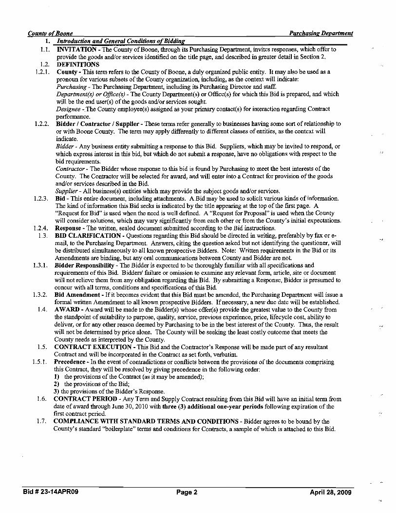
Countv of Boone Purchasing Department 1. Introduction and General Conditions of Bidding
1.1. INVITATION - The County of Boone, through its Purchasing Department, invites responses, which offer to provide the goods andlor services identified on the title page, &d described in greater detail in Section 2.
1.2. DEFINITIONS 1.2.1. County - This term refers to the County of Boone, a duly organized public entity. It may also be used as a
pronoun for various subsets of the County organization, including, aB the context will indicate: ~ u r c h a s i n ~The Purchasing Department, including its Purchasing Director and staff. -Department(s) or Ofice(s) - The County Department(s) or Office(s) for which this Bid is prepared, and which will be the end user(s) of the goods andlor services sought. Designee - The County employee(s) assigned as your primary contact(s) for interaction regarding Contract performance.
1.2.2. Bidder / Contractor / Supplier - These terms refer generally to businesses having some sort of relationship to or with Boone County. The term may apply differently to different classes of entities, as the context will indicate. Bidder - Any business entity submitting a response to this Bid. Suppliers, which may be invited to respond, or which express interest in this bid, but which do not submit a response, have no obligations with respect to the bid requirements. Contractor- The Bidder whose response to this bid is found by Purchasing to meet the best interests of the County. The Contractor will be selected for award, and will enter into a Contract for provision of the goods and/or services described in the Bid. Supplier - All business(s) entities which may provide the subject goods and/or services.
1.2.3. Bid - This entire document, including attachments. A Bid may be used to solicit various kinds of information. The kind of information this Bid seeks is indicated by the title appearing at the top of the first page. A "Request for Bid" is used when the need is well defined. A "Request for Proposal" is used when the County will consider solutions, which may vary significantly from each other or from the County's initial expectations.
1.2.4. Response - The written, sealed document submitted according to the Bid instructions. 1.3. BID CLARIFICATION - Questions regarding this Bid should be directed in writing, preferably by fax or e-
.A
mail, to the Purchasing Department. Answers, citing the question asked but not identifpg the questioner, will be distributed simultaneously to all known prospective Bidders. Note: Written requirements in the Bid or its Amendments are binding, but any oral communications between County and Bidder are not.
1.3.1. Bidder Responsibility - The Bidder is expected to be thoroughly familiar with all specifications and requirements of this Bid. Bidders' failure or omission to examine any relevant form, article, site or document will not relieve them from any obligation regarding this Bid. By submitting a Response, Bidder is presumed to concur with all terms, conditions and specifications of this Bid.
1.3.2. Bid Amendment - If it becomes evident that this Bid must be amended, the Purchasing Department will issue a formal written Amendment to all known prospective Bidders. If necessary, a new due date will be established.
1.4. AWARD - Award will be made to the Bidder(s) whose offer(s) provide the greatest value to the County from the standpoint of suitability to purpose, quality, service, previous experience, price, lifecycle cost, ability to deliver, or for any other reason deemed by Purchasing to be in the best interest of the County. Thus, the result * A
will not be determined by price alone. The County will be seeking the least costly outcome that meets the County needs as interpreted by the County.
1.5. CONTRACT EXECUTION - This Bid and the Contractor's Response will be made part of any resultant Contract and will be incorporated in the Contract as set forth, verbatim.
1.5.1. Precedence - In the event of contradictions or conflicts between the provisions of the documents comprising this Contract, they will be resolved by giving precedence in the following order: 1) the provisions of the Contract (as it may be amended); 2) the provisions of the Bid; 3) the provisions of the Bidder's Response.
1.6. CONTRACT PERIOD - Any Term and Supply Contract resulting from this Bid will have an initial term from date of award through June 30,2010 with three (3)additional one-year periods follo&ng expiration of the first contract period.
1.7. COMPLIANCE WITH STANDARD TERMS AND CONDITIONS - Bidder agrees to be bound by the County's standard '%oilerplate" terms and conditions for Contracts, a sample of which is attached to this Bid.
Bid # 23-14APR09 Page 2 April 28,2009

Countv o f Boone Purchasin~De~artment 2. Primary Specifications
2.1. ITEMS TO BE PROVIDED -Emergency vehicle equipment items, light bars, and sirens. 2.1.1. Contract Documents -The successful bidder(s) shall be obligated to enter into a written contract with the
County within thirty (30) days of award on contract forms provided by the County. If bidders desire to contract under their own written agreement, any such proposed agreement shall be submitted in blank form with their bid. The County reserves the right to modify any proposed form agreement or withdraw its award to a successful bidder if any proposed agreement contains terms and conditions inconsistent with its bid or are unacceptable to County legal counsel.
2.1.2. Contract Extension -The County Purchasing Director may exercise the option to extend the contract on a month-to-month basis for a maximum of 6 months fiom the date of termination if it is deemed to be in the best interest of Boone County.
2.2. Federal Signal Corporation Legend LED Lightbar (including the HotFootTM Mounting System) 2.2.1. This specification describes the minimum requirements for a low profile lightbar utilizing LED technology for
emergency vehicles manufactured by Federal Signal Corporation. The lightbar system shall utilize Solaris S2 reflector LED based technology and Reliable Onboard Circuitry (ROC) manufacturing design. The lightbar system must include an upper-level (primary) and lower-level (secondary) light source. Single-level lightbar warning systems shall not be acceptable.
2.3. PlUMAFiYWARNlNG 2.3.1. Light emitting diode (LED) light heads shall consist of Solaris S2 reflector modules utilizing high output LED
technology. Each Solaris S2 module shall use a compound-curve and polished reflector design and shall contain three or six diodes. Solaris S2 reflector modules shall be available in red, blue, white, and amber LEDs. Each lightbar shall contain a total of hrty Solaris S2 reflector modules. A total of eleven red Solaris S2 modules, eleven blue Solaris S2 modules, four amber Solaris S2 modules, and four white Solaris S2 modules (TDIAL) shall be included. The maximum total number of Gen 3 lamp diodes shall be one hundred thirty-eight (1 38).
2.3.2. Reliable onboard circuitry technologies shall be utilized. Legend lightbar design shall utilize surface mounted LEDs projecting downward into the Solaris S2 reflector assemblies. ROC technology shall use microprocessor controls to provide a total of twenty-six user-selectable flash patterns, including an intersection mode, two test patterns and a low power 'dim' mode. ROC circuitry shall be field replaceable and shall meet the approval of the following specifications: SAE 11 13/41 RFI and SAE 5845. No exceptions shall be allowed.
2.3.3. The Legend lightbar shall function with three prioritized modes of operation. Mode 3 shall be the highest z z
priority and shall override both Mode 2 and Mode 1. Mode 2 shall override Mode 1. Each of the three modes will provide preset (default SAE J845/CCR, Title 13) flash patterns that can be activated for various stages of the emergency vehicle's warning light levels of operation. A total of twenty-six flash patterns are available for mode selections.
2.3.4. Intersection flash mode of operation: The lightbar shall provide a high activity pattern that attracts attention to the vehicle as it approaches an intersection. Intersection operation shall be able to be controlled by three selected options including Power On-Off function, TAP11 (push-ontpush-off) by using a momentary contact switch or horn ring button or 8-second timer activation.
2'3'5 FrontiRear Cutoff or Enable function: The lightbar shall be able to provide a fiondrear cutoff and fiondrear enable function. Frondrear cutoff is controlled by applying 12 VDC to supplied controlled wires. Frondrear enable activates the LED modules when +Bat is applied to their control wires. This function allows the lightbar to be custom programmed to meet a wide range of departmental needs and installed light controls.
2.3.6 The Legend lightbar shall be able to operate in the low power mode if desired. The lightbar shall be capable of dimming the main bar LEDs approximately 50% to prevent blinding of approaching vehicles. The low power function shall only operate in Mode 1 or Mode 2 levels. It is disabled when the lightbar is turned off or switched to another flash pattern, including Mode 3 or the intersection mode level. Lightbars that dim in level 3 or during the pursuit mode shall not be accepted, no exceptions will be allowed.
2.3.7 The lightbar shall have zero standby current (mA) while it is not in operation. This helps reduce vehicle electrical draw while the car is not in use.
2.4. HOUSING-BODY 2.4.1. The solid aluminum extrusion shall be of a 118'' minimum thickness design to provide strength and durability
without excessive weight. The mounting feet and bases for light mechanisms attach directly to the extrusion's integrated mounting channel which provides a well-secured mounting platform.
2.4.2. The lightbar housings shall be molded polycarbonate for durability and strength. Both domes shall be secured to the extruded aluminum fiame by use of four barrel nut with O-ring seals and bolt assemblies. A lip seal gasket shall be around all external perimeters to provide a weatherproof seal. The upper level domes must
Bid # 23-14APR09 Page 3 April 28, 2009

incorporate a honeycomb-molded design to maximize strength and reinforcement for the internal lightbar components from hail and unforeseen impact. The upper level domes shall be clear (driver), and clear (passenger). The lower level domes shall be clear. Lower housing shall be a smooth one piece molded polycarbonate construction. No vertical gaskets, multi segmented lenses or exterior mounted LED modules are acceptable. Lower housing should have a minimum of (8) one way vent plugs that allows condensation to be vented during changing environment conditions. Domes shall mount on top of the lower housings with barrel nuts with O-ring seals. Dome mounting clips and standard bolts are not acceptable. SERIAL INTERFACE MODULE The serial interface module is the device used to communicate with the Legend lightbar. Each lightbar shall be controlled via a standard RS485 bus connection with protocols based upon SAE standards 51708 and ;
51587. A serial interface module shall be included (FS model #Z8583446) that transitions from the RJ-style connection to the 24-conductor control link cable harness. Lightbar hook-up shall require only a 10-ga power cable, a 10-ga ground cable, and a 25' snap-in CAT 5 communication cable. Both the 10-ga power and the 10-ga ground cables shall measure twenty-one feet in length -no exceptions. The lightbar shall be capable of being removed fiom the vehicle without disassembly of the vehicle's emergency light controller's wiring system for ease of service or repair. LOWER-LEVELISECONDARY WARNING An integral component of the lightbar shall be the lower-level HotFoot mounting and light system. The HotFoot design shall serve as both a secondary warning light source and as a roof mounting system. Each mounting foot assembly shall include four LED modules. The HotFoot shall be constructed of glass-filled nylon and is available in black The LED housings shall be made of die cast aluminum and the LED lenses shall be clear polycarbonate plastic.
The mounting foot light assembly shall contain two LED takedown modules, and shall consist of six GEN I11 high brightness LEDs. LED takedown light assemblies shall be adjustable horizontally by positioning them straight, at 45 degrees or at 90 degrees. Each position has +I- 10 degrees of adjustment.
The mounting foot light assembly shall contain two LED alley modules, and shall consist of six GEN I11 high brightness LEDs. LED alley lights shall be adjustable horizontally by positioning them straight, at 45 degrees or at 90 degrees. Each position has +I- 10 degrees of adjustment.
As a convenience to the end user installer, for shipping purposes, and to further aid in the speed of installation, the HotFoot mounting legs will be installed to the base extrusion of the lightbar at a preset distance apart.
SIGNALMASTER A six-lamp LED SignalMaster traffic management device shall be built into the lightbar and standard for the Legend. Light heads shall consist of six Solaris S2 reflector modules.
The Legend lightbar shall be configured at the factory for 'external' SignalMaster control. When used with the appropriate (optional) SignalMaster controller, this device shall produce three distinct signals: left arrow sweep, right arrow sweep, and center arrow out and user selectable warning patterns.
The Legend lightbar can be configured for 'internal' SignalMaster control operation. In this mode, an external SignalMaster controller is not required. 12V applied to the specified control lead shall activate the lightbar's internal SignalMaster controller. Internal operation functions shall include: Left, Center, Right, Warn 1: Outer LEDs alternate, Warn 2: Two outer LEDs alternate, Warn 3: Outer LEDs and two LEDs alternate, Warn 4: Outer LEDs and two inner LEDs flash, then the LEDs between the inner and outer LEDs; and Fast operates the selected pattern 50% faster. When the lightbar is operating in any of the three priority flashing modes, all SignalMaster modules shall emulate the selected flash patterns. When the operator activates the SignalMaster, the directional warning patterns shall override any other activity in that portion of the lightbar. Lightbars that are not capable of this feature shall not be accepted.
MOUNTING BRACKETS
A hook-on mounting bracket with stainless steel hardware must be included and be compatible for vehicles with or without rain gutters. Mounting legs may be adjusted by the installer to meet a variety of roof width requirements of the specified vehicle. Three pair of rubber mounting pads shall be included and vary in height: short, medium, and tall. Mounting pads can be installed to determine the overall height of the lightbar off the roof of the vehicle and can compensate for various roof pitches and slope angle adjustments.
ELECTRICAL
Bid # 23-14APR09 Page 4 April 28, 2009

Three lightbar programming mode options: The lightbar shall be able to support three user selectable programming modes. The lightbar can be programmed on the vehicle or outside the vehicle (i.e., bench). It can also be programmed with an optional ROC interface cloning kit (ROCPR1) which uses the installed vehicle light control and cloning flash patterns fiom an existing lightbar.
Fuse'Protection: The lightbar shall provide multi levels of electrical connection protection for the vehicle and lightbar. The fist level of lightbar protection shall have a 40A max fuse protection on 10 Ga positive lead going to the lightbar. The lightbar controller shall have six fuses ranging from 5A to 20A to prevent possible damage to the lightbar or vehicle.
LED light heads must meet the approval of the following specifications: SAE 11 13141 RFI, SAE J845 and FCC Part 15.
Total current requirements (rated in amperes) at 12.8 VDC shall not exceed:
-- Solaris S2 LED takedown light in HotFoot -1.0 A*
-- Solaris S2 LED alley light in HotFoot - 1.0 A*
-- Solaris S2 4" and 5" flashing positions - 1.0 A*
-- Solaris S2 2" flashing positions - 0.5 A*
* Amperage in steady burn mode RFI (Radio Frequency Interference) The LED Solaris module system shall incorporate a unique suppression circuit design that greatly minimizes RFI (Radio Frequency Interference) noise associated with LED technology. RFI can greatly reduce public safety two-way radio reception sensitivity and interfere with vehicular laptop computer performance operation. The lightbar must meet the requirements of Test Specification 11452-2 and J'1113-21 for Radiated Immunity and Test Specification CISPR 25 for Radiated Emissions. DIMENSIONS/WARRANTY/PRODUCTREFERENCE 45" Legend - The lightbar shall have maximum dimensions of 2.5" in height, 1 1.2" in width, 44.5" in overall length, and weigh 27.6 pounds (with HotFoot). The warranty period shall be three years parts replacement and one year labor coverage. LED components shall be covered by five years parts replacement and one year labor coverage.
A complete system shall include the Legend lightbar, a vehicle specific hook kit (2009 Ford Crown Victoria Police Interceptor), the interface module and a pigtail wire harness. The lightbar shall be manufactured by the Federal Signal Corporation and shall be the Legend model LGD45H-00013.
Anticipated quantity to purchase in 2009 = 2 FEDERAL SIGNAL CORPORATION SPECIFICATION SS2000SM-SD SMART SIREN The Smart Siren w l ~ i ~ n a l ~ a s t e r ~ ~ shall consist of a 1-114" thin keypad control head and remote amplifierlSMC (SignalMaster Contro1)lrelay unit. Communication between the control head and the amplifierlSMC1relay unit is via an RJ11 serial link. The intelligence of the system is contained in the remote amplifierlSMC1relay unit. All system functions are controlled by the control head except for PIT, TapII, Pursuit, and Park Siren Deactivation features.
CONSTRUCTION 1.Dimensions of the control head shall be 3-118" in height, by 6-314" in width and 1-114" in depth. The amplifier1SMCLRelay unit shall be 3-118" in height by 6-318" in width and 6-114" in length. 2. An adjustable steel trunion mounting bracket and associated hardware shall be provided for mounting the unit in a vehcle. 3. All housings, chassis, bracket and other ferrous parts shall be protected from corrosion by plating or painting. 4. AmplifierISMClrelay circuit boards shall be wired in a manner that will permit access to all three without unsoldering connections, and shall be mounted in the chassis for easy access and maintenance. 5. AmplifierISMClrelay housing shall be constructed to be immune to radio fiequency interference (RFI) and electromagnetic interference (EMI). 6. All power inputs, speaker outputs and other connections should be of a quick disconnect type or screw barrier type. 7. Both the amplifierlSMC1relay and control head shall be clean bottom, free from any fuse holders, fuses, output transistors or heat sinks.
Bid # 23-14APR09 Page 5 April 28, 2009

8. A separate control head allows the amplifierlSMC1relay unit to be remotely mounted. 9. The control head shall have the capability of interchangeable custom legends for designating functions. A sheet of applicable function legends shall be supplied. 10.All connections to the barrier strip on the rear of the amplifierlSMC1relay unit housing must be of a clamp type, not requiring additional crimped connectors.
1 1. Connection to the control head fiom the arnplifierlSMC1relay unit shall be via a RJ11 telephone cable with telephone type connectors. Connections for ignition, ground, horn ring, horn, radio rebroadcast, pursuit and
"'2
speaker must be via a twelve-pin Molex type connector. Connection to the signalMasterTM shall be via a two- piece, quick disconnect terminal block. 12.Terminals shall be provided at the rear of amplifier the ISMCIrelay unit for a convenient junction point for the light and auxiliary functions.
2.14. ELECTRICAL 2.14.1. 1. The unit shall be designed for negative ground vehicles. Normal operating voltage shall be 1 1.0 to 16.0
VDC. 2. The unit shall be protected by a 20-ampere fuse. 3. The electronic siren circuit shall have reverse polarity protection to insure that damage shall not occur to the siren, except possible fuse replacement should the polarity of the supply voltage be accidentally reversed. 4. Power shall be controlled through the positive ignition input. 5. Volume control for radio rebroadcast and PA should be located in the amplifierlSMC1relay unit and be preset. 6. The control head unit shall be backlit with LED indicators. Intensity of the LED'S may be adjusted or turned off with the backlighting. 7. The unit shall have relays on a separate printed circuit board. One output rated at 40 amperes, two at 20 amperes and five at 10 amperes. 8. Fuses on the relay and SMC boards shall be of the automotive blade type. The control head shall also to be protected by a fuse in the amplifierlSMC1relay unit. The Smart Siren System shall contain a total of eleven fuses. 9. The remote amplifier shall have a 114" diameter phone jack for the optional transistorized noise canceling microphone (MNCT) andlor optional microphone extension kit (RMK).
2.15. PERFORMANCE 2.15.1. 1. The Wail, Yelp, Priority, and Hi-Lo frequency shall be a nominal 700HZ to 1500HZ.
2. The Wail tone shall cycle at a nominal rate of 12 cycles per minute. 3. The Yelp tone shall cycle at a nominal rate of 180 cycles per minute.
4. The Hi-Lo tone shall cycle at a nominal rate of 60 cycles per minute. 5. The Priority tone, A/Htone, and manual siren tones are available. 6. Siren output voltage: 64V peak-to-peak nominal at lOOW tap with 1 1-ohm load. 7. Audio output power (PA and radio): 45W RMS nominal with 1 1-ohm load. 8. Audio harmonic distortion less than 10% of 1000 HZ reference at 13.6V battery from 5 watts through 45 watts. 9. Operating temperature range shall be 30 degrees to +65 degrees Celsius. 10. The signalMasterTM controller output drive maximum capability is eight 27-watt lamps. It can be configured to control six. 1 1. The signalh4asterTM normal directional flash rate is 35 patterns per minute. The normal warn flash rate is 60 patterns per minute. The fast directional flash rate is 60 patterns per minute. The fast warn flash rate is 95 patterns per minute.
2.16. FORMAT 2.16.1. 1. The control head with the four (4) position slide switch and seventeen (17) push on - push off switches shall
provide selection and programming of the following functions: a) Programming of the various features is performed fiom the switches on the control head, without disassembly or removal of the unit from its mounting location. b) The @ row of the control head switches operates the SignalMaster functions. The middle row of control head switches operates the siren functions. The bottom row of the control head switches and the slide switch are all capable of being programmed to control the emergency vehicle's warning lights, SignalMaster patterns, and auxiliary functions. c) The slide switch positions located on the bottom row of the control head can be programmed to activate one or more light functions. Mode 1,2 or 3 of the slide switch can be programmed to automatically generate a siren tone, pre-selected upon power up or manually selected. The siren tones can also be programmed to generate a siren tone independent of the slide switch.
Bid # 23-14APR09 Page 6 April 28,2009

Each slide switch position can be configured to operate any combination of all eight relays plus Key 11, Horn Ring Transfer, Siren Enable, and SignalMaster WARN patterns. d) The five auxiliary switches can be programmed to be push-onlpush-off, momentary or eight-second timer. All eight-second timers can be set-up as a security timer (two switches need to be pressed for timer to operate). The security timer is especially effective when actuating shotgun locks.
e) The horn ring can be programmed to activate in Modes 1,2 or 3, or can be independently controlled using a control head switch. Smart Siren technology allows the operator to select the siren sound (Wail, Yelp, Hi-Lo, Priority) available at "power up" as well as via the horn ring. Horn ring can be programmed to activate manual siren or air horn. f ) Adhesive backed function legends identify the switches. A legend card consisting of one hundred and forty (140) legends shall be supplied with each unit. No disassembly is required to install the legends. g) Radio rebroadcast provides amplification of incoming radio messages through the outside loudspeaker. h) Public address controls optional FN module to provide PA operations or can be configured to operate the horn ring transfer. i) Wail provides a continuous cycling of the siren tone fiequency at a rate of 12 nominal cycles per minute. j) Yelp provides a continuous cycling of the siren tone fiequency at a nominal rate of 180 cycles per minute. k) Hi-Lo provides an alternating high and low tone at a nominal rate of 60 cycles per minute. 1) The Priority tone can be programmed in place of the Hi-Lo tone. m) Auxiliary remote input allows simple push button activatiodde-activation (pursuit) of mode 3, or toggle between modes 2 and 3, or can be configured to deactivate the siren when in Park. 2. Public address shall ovemde siren functions upon activation of the microphone. 3. The unit shall have a momentary push button on the control head to operate the air horn tone. 4. The unit shall have a momentary push button on the control head, which will operate manual siren. Manual siren shall also have capability to operate Tap I1 feature. 5. The control head shall have rubberized push on push off switches, and a four-position slide switch. 6. The unit shall accept both positive and ground horn ring switch circuits without determining the polarity of the horn ring circuit, or changing any external or internal switches or internal wiring.
7. An "instant Yelp" or "instant Priority" option shall be available through the horn ring circuit when operating in the wail mode. Instant Yelp or Priority shall also have the capability of being programmed to revert back to Wail after eight seconds. 8. The Smart Siren shall be capable of operating 58, 100, andfor 200-watt vehicular siren speakers. 9. Relays sequence on and off to minimize power surges. 10. The programming mode can be disabled to prevent tampering. 11.The SignalMaster controller can be programmed to operate six lamp or eight lamp SignalMasters.
12.The SignalMaster can perform six directional patterns (left, right, center-out and the low power patterns of left right and center-out), four alternating warning patterns, and a fast version of all of the previous patterns.
2.17. WARRANTY & PRODUCT REFERENCE 2.17.1. The warranty period shall be three years parts and one-year labor coverage. The siren shall be the Federal
Signal Corporation model SS2000SM-SD, including the optional MNCT microphone and RMK cable kit.
2.17.2. Anticipated quantity to purchase in 2009 = 2 2.189. Dodge Charger Emergency LightinglSiren System Specifications (Whelen Products)
2.18.1. It is the department's intent to purchase the warning system from one vendor; therefore, all components must be made by one manufacturer. Bids for equipment fabricated by more than one manufacturer will be considered unacceptable. The emergency vehicle warning equipment must be manufactured by a single company and must contain the following equipment: 107UF8; I07LR8L; PEIMDOC08; FEDC06RR and FEDC06BR; LINZ6R and LINZ6B with (2) RBKT1; LAW2CC; CCSRN2 with CCMICX20; (2) SA315P with (2) SAK18; IBDC06JJ, as described below.
2.18.2. SUPER-LED INTERIOR LIGHT BAR - INNER EDGE (FRONT) 2.18.3. 1. The device shall be housed in two individual heavy duty polycarbonate housings with a clear outer lens for
stealth look. Both units shall appear to be void of color until the Super-LED'S are turned on. Each unit must be supplied with mounting brackets for ease of mounting in a 2009 DODGE CHARGER,one on the driver side, the other on the passenger side of the vehicle, and will be designed to fit snuggly to the windshield to prevent flash back into the passenger compartment. 2. Each housing shall contain four (4) Super-LED panels. Each LED must be a high intensity Generation 3.5 Super-LEDs (Light Emitting Diodes). Each housing must have four (4) lamps facing straight out of the housing and one (1) MR8 take-down light mounted in the inboard position [4 Red Driver Side 1 4 Blue Passenger Side]. These LED'S shall have a life expectancy of at least 100,000 hours. Each LED segment
Bid # 23-14APR09 Page 7 April 28, 2009
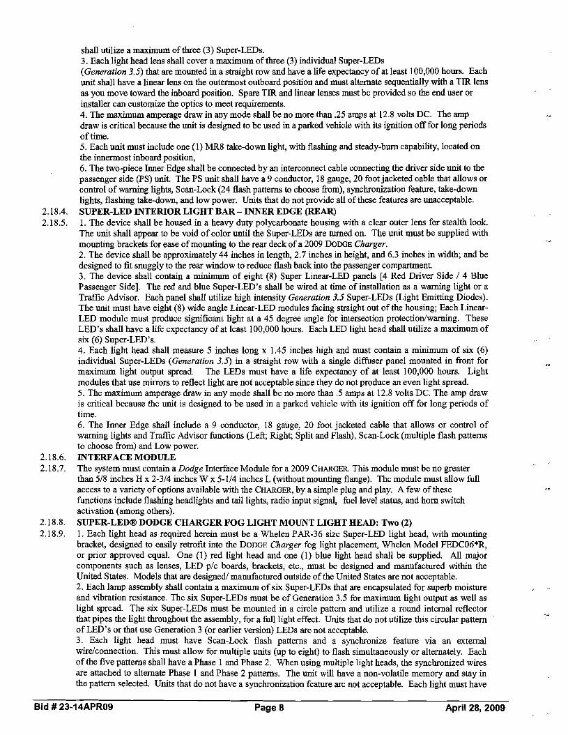
shall utilize a maximum of three (3) Super-LEDs. 3. Each light head lens shall cover a maximum of three (3) individual Super-LEDs (Generation 3.5) that are mounted in a straight row and have a life expectancy of at least 100,000 hours. Each unit shall have a linear lens on the outermost outboard position and must alternate sequentially with a TIR lens as you move toward the inboard position. Spare TIR and linear lenses must be provided so the end user or installer can customize the optics to meet requirements. 4. The maximum amperage draw in any mode shall be no more than .25 amps at 12.8 volts DC. The amp draw is critical because the unit is designed to be used in a parked vehicle with its ignition off for long periods of time. 5. Each unit must include one (1) MR8 take-down light, with flashing and steady-burn capability, located on the innermost inboard position, 6. The two-piece Inner Edge shall be connected by an interconnect cable connecting the driver side unit to the passenger side (PS) unit. The PS unit shall have a 9 conductor, 18 gauge, 20 foot jacketed cable that allows or control of warning lights, Scan-Lock (24 flash patterns to choose fiom), synchronization feature, take-down lights, flashing take-down, and low power. Units that do not provide all of these features are unacceptable.
2.18.4. SUPER-LED INTERIOR LIGHT BAR -INNER EDGE (REAR) 2.18.5. 1. The device shall be housed in a heavy duty polycarbonate housing with a clear outer lens for stealth look.
The unit shall appear to be void of color until the Super-LEDs are turned on. The unit must be supplied with "-mounting brackets for ease of mounting to the rear deck of a 2009 DODGE Charger.
2. The device shall be approximately 44 inches in length, 2.7 inches in height, and 6.3 inches in width; and be designed to fit snuggly to the rear window to reduce flash back into the passenger compartment. 3. The device shall contain a minimum of eight (8) Super Linear-LED panels [4 Red Driver Side / 4 Blue Passenger Side]. The red and blue Super-LED'S shall be wired at time of installation as a warning light or a Traffic Advisor. Each panel shall utilize high intensity Generation 3.5 Super-LEDs (Light Emitting Diodes). The unit must have eight (8) wide angle Linear-LED modules facing straight out of the housing; Each Linear- LED module must produce significant light at a 45 degree angle for intersection protectionlwarning. These LED's shall have a life expectancy of at least 100,000 hours. Each LED light head shall utilize a maximum of six (6) Super-LED'S. 4. Each light head shall measure 5 inches long x 1.45 inches high and must contain a minimum of six (6) individual Super-LEDs (Generation 3.5) in a straight row with a single diffuser panel mounted in fiont for maximum light output spread. The LEDs must have a life expectancy of at least 100,000 hours. Light modules that use mirrors to reflect light are not acceptable since they do not produce an even light spread. 5. The maximum amperage draw in any mode shall be no more than .5 amps at 12.8 volts DC. The amp draw is critical because the unit is designed to be used in a parked vehicle with its ignition off for long periods of time. 6. The Inner Edge shall include a 9 conductor, 18 gauge, 20 foot jacketed cable that allows or control of warning lights and Traffic Advisor functions (Left; Right; Split and Flash), Scan-Lock (multiple flash patterns to choose fiom) and Low power.
2.18.6. INTERFACE MODULE 2.18.7. The system must contain a Dodge Interface Module for a 2009 CHARGER. This module must be no greater
than 518 inches H x 2-314 inches W x 5-114 inches L (without mounting flange). The module must allow full access to a variety of options available with the CHARGER, by a simple plug and play. A few of these hc t ions include flashing headlights and tail lights, radio input signal, fuel level status, and horn switch activation (among others).
2.18.8. SUPER-LED@ DODGE CHARGER FOG LIGHT MOUNT LIGHT HEAD: Two (2) 2.18.9. 1. Each light head as required herein must be a Whelen PAR-36 size Super-LED light head, with mounting
bracket, designed to easily retrofit into the DODGE Charger fog light placement, Whelen Model FEDC06*R, or prior approved equal. One (1) red light head and one (1) blue light head shall be supplied. All major components such as lenses, LED plc boards, brackets, etc., must be designed and manufactured within the United States. Models that are designed1 manufactured outside of the United States are not acceptable. 2. Each lamp assembly shall contain a maximum of six Super-LEDs that are encapsulated for superb moisture and vibration resistance. The six Super-LEDs must be of Generation 3.5 for maximum light output as well as light spread. The six Super-LEDs must be mounted in a circle pattern and utilize a round internal reflector that pipes the light throughout the assembly, for a full light effect. Units that do not utilize this circular pattern of LED's or that use Generation 3 (or earlier version) LEDs are not acceptable. 3. Each light head must have Scan-Lock flash patterns and a synchronize feature via an external wirelconnection. This must allow for multiple units (up to eight) to flash simultaneously or alternately. Each of the five patterns shall have a Phase 1 and Phase 2. When using multiple light heads, the synchronized wires are attached to alternate Phase 1 and Phase 2 patterns. The unit will have a non-volatile memory and stay in the pattern selected. Units that do not have a synchronization feature are not acceptable. Each light must have
Bid # 23-14APR09 Page 8 April 28, 2009

an extended lens that protrudes out a minimum of 1-118 inch fiom the LED assembly. This is required for superb light coverage, even at wide angles. 4. Each light head, less mounting bracket, shall be approximately 4.4 inches in diameter x 2.2 inches deep, and weigh 6 ounces. It must be supplied with a 6 inch pigtail and mounting that allows the unit to be inserted into the DODGE Charger fog light shroud. 5. The lens must have built-in optics for maximum light spread and shall be made of impact-resistance polycarbonate (glass lenses are not acceptable). he lens color shall be clear and shall be in accordance with SAE requirements (coated or painted lenses are not acceptable).
2.18.10. LINZ6 WARNING LIGHTS: Two (2) 2.18.11. 1. The system must contain a minimum of two (2) LINZ6s (1 Red11 Blue). Each directional light head
assembly shall be supplied with an aluminum mounting plate and a black flange as standard and will be completely sealed for long life and durability. The unit must be designed to mount to any flat surface. 2. Each light head assembly shall measure a maximum 4 inches long x 1-518 inch protrusion, x 2 inches high with the mounting flange. Larger units are not acceptable due to the size constraint of the mounting area. 3. Each directional head assembly shall have a Linear6 LED panel which contains a maximum of six (6) individual Super-LEDs (Generation 3.5) in a straight row that have a life expectancy of at least 100,000 hours. The panel must be completely encapsulated for long life and durability. The unit shall draw no more than .5 amps. 4. There must be four (4) wires exiting each unit, one for each of the following: Power, Ground, ScanLock and Synchronize. The Scadock wire will allow a choice of sixty-nine (69) flash patterns including steady burn. Each light must have eight patterns that allow for alternating or simultaneous flash of each color segment (3x3). When using multiple light heads, the synchronized wires are attached to alternate Phase 1 and Phase 2 patterns. The unit will have a non-volatile memory and stay in the pattern selected. Units that do not have a synchronization feature are not acceptable. 5. The lens must be made of clear polycarbonate and must have a smooth non-optic outer lens to insure maximum light output. 6. Each light must be supplied with an "L" style universal mounting bracket. Each bracket shall measure 3.75 inches long x 2.18 inches high x 1 inch deep; made of aluminum and powder-coated in black.
2.18.12. LED LAMP DRIVER 2.18.13. 1. The LED Lamp Driver shall be designed with the latest solid-state circuitry, no moving parts, and will
incorporate design features for maximum vibration resistance. This includes weather-resistant materials and assembly techniques to withstand a range of temperature or environmental conditions. 2. The Lamp Driver must be completely encapsulated for superb moister and vibration resistance and must have a minimum of two output outlets, each using 6-position waterproof connectors and a 4-position waterproof connector for input power, ground, Scan-Lock, and Synchronization. All connectors must be mounted in the encapsulate for moisture resistance. 3. The overall dimensions shall measure no more than 6- 112 inches long (with mounting flange; 5- 114 inches without) x 2-314 inches wide x 518 inch hgh (not including the connectors) for easy installation in the engine compartment, under the seat, near fire wall, or any other out-of-the-way, hidden location. 4. The Lamp Driver shall be 12 volts DC, and operate through the range of 10-16 volts DC with no degradation of performance in either intensity or flash rate. Maximum current draw shall be 3 amps at 12.8 volts, with an average current of .6 amps. 5. The Lamp Driver must be capable of up to a minimum of eighty-five (85) flash patterns. These flash patterns must be selected by a single wire, positive activation allowing the user to toggle through all eighty- five patterns. The unit shall have non-volatile memory so when the unit is turned "off" and "on", it always returns to the last pattern selected.
2.18.14. REMOTE CONCEALED SUPER-LED HEADS 2.18.15. 1. The system shall include two (2) plug-in mounted LED lamp assemblies that have a minimum of four (4)
LED panels, each with three Super-LEDs (total of a minimum of 12 Super-LEDs per assembly) that mounts into a black cast aluminum base, and a 6 position connector, and will come complete with one (1) 6 ft. and one (1) 10 ft. harness. Both of the connections on the light head end and lamp driver end must include a waterproof mating connector to allow easy installation to the LED head and the lamp driver. 2. The base shall be designed for easy mounting into a maximum 314 inch hole inside a "composite-style" headlight or tail light assembly. Units that require larger than a 314 inch diameter hole are unacceptable. The unit shall be flange mounted with two screws and contain a built-on gasket to produce a waterproof seal that secures the lamp assembly to the housing. For upgrading existing strobe systems to LED, the base and gasket must allow the LED lamp to mount into the existing one-inch holes. 3. Two (2) Clear LED lamps shall be supplied and shall be designed to work in conjunction with the above- referenced Lamp Driver. The unit must be a maximum of 1-718 inches tall x 1-114 inches in diameter (less mounting flange). Light heads that are larger than these dimensions are unacceptable as they block too much
Bid # 23-14APR09 Page 9 April 28, 2009

of the OEM reflector. 2.18.16. SIREN AMPLIFIER, CONTROL HEAD & AMPLIFIERIRELAY MODULE (ARM) 2.18.17. 1. The remote siren system shall consist of a control head with a 4-position slide switch and (18)
programmable push button switches, and a combined electronic siren amplifier and relays in (1) module. It utilizes a small single 8 conductor 22 gauge cable to connect the control head to the AMPRelay Module as described in the following specification. 2. The control head shall be supplied with a two-position bail bracket and all necessary mounting hardware. The unit shall be no larger than 2.15 inches deep (including slide switch) x 3-518 inches high x 6-13/16 inches wide (excluding mounting hardware). As an option, there must be a semi-flush trim ring for mounting the control head into a dashlpanel. 3. The control head connector shall be built into the back of the unit. The wire harness shall follow a built-in channel (inlet) on the back of the control head and will exit the bottom or side of the unit. This will act as a strain relief and allow the control head to be easily mounted where space is of key consideration. If the harness is to exit straight out of the back of the control head, the unit must have an area designated for a tie- wrap to secure the harness to the control head (to act as a strain relief). 4. The control head must incorporate a single circuit board design equipped with a solid silicon rubber overlay for maximum moisture resistance from water or beverage spills. Each push button switch must have both tactile and audible ("beep") feedback to the user. Each switch will also produce a "clicK' sound when pushed OdOff as another positive feedback method that the switch has been changed. Control heads that do not have this feature are not acceptable since the driver would have to take his eyes off the road to determine if the switch is operating. Control heads with multi-board designs are unacceptable; since the internal interconnect cable can become disconnected unknowingly, with service not user friendly. 5. Each tactile switch must be filly programmable and must allow the placement of any siren or light function in any push button switch position for complete programmability by the end user via a Windows-based program that must be included. Each tactile switch must be backlit in green and each switch must include a s2
separate Red LED "On" indicator above the switch face that provides enough light to allow it to be seen even in bright day light without washing out. Both the switch backlight and the LED "On" indicator must have a low intensity feature for ease of night time visibility. Units that are not backlit or which do not have a separate LED "On" indicator visible in bright day light are not acceptable. Each of the push button switches shall have its own back-lit legend tab. This will help in identifying the functions that are in use. There shall be a total of (136) legends to choose from. 6. The control head shall be supplied completely assembled with a 4-position (positive detent) slide switch that is programmable, and (1 8) push button switches that directly interface with the control head electronics and operates external equipment such as light bars, headlight flashers, Traffic Advisors, etc. 7. The control head shall have (8) OnIOff siren switches across the first row: Stand-By; Radio Repeat; Hands- Free; Wail; Yelp; Piercer (or Hi/Lo); Manual (manual coast down or manual stop); and Airhorn. The second
az
row shall contain (5) switches: Traffic Advisor Direction Control (Leji, Right,Split); Traffic Advisor Flash Patterns (3 dzfferentpattems); Aux 1; Am 2; and Low Power. The third row of five switches will activate (4) 10 amp circuits and (1) switch will operate an open, dry contact relay in the AMPtRelay Module. All (5) switches are programmable for OdOff; Momentary; 8 Second Timer or Double Tap Security 8 Second Timer. A 4-position slide switch shall be located in the bottom left-hand corner. It shall be programmable as independent switches or progressive, and will have (2) 20 amp and (1) 40 amp positions. The slide switch must be programmable to include either Wail with Yelp ovemde or Hands Free operation in any one of the three "On" positions. Each slide switch position will also be programmable to operate Traffic Advisor flasher mode, AuxlIAux 2, Low Power and all (5) programmable switches. 8. The aluminum housing of the ARM shall have built-in ventilator ports to assist in keeping all internal components cool for long life and reliability. It shall be supplied with (2) mounting feet that must be built into the design of the assembly for superior strength, and includes all necessary mounting hardware. The amplifier shall measure approximately 6.825 inches wide x 6.725 inches deep x 3.0 inches high. 9. The ARM operates on a 12 volt negative ground automotive electrical system. The amplifier shall be designed to operate from 10V to 15V and shall be reverse-polarity protected to ensure that the unit will not be damaged if polarity is reversed. 10.To ensure ease of service, the ARM shall have all power and control connectors on one side of the module, and all fuses shall be accessible from the outside of the unit without disassembling the unit to access fuses accessible located on top of the module or next to the connectors. There shall be (3) heavy duty Anderson style power connectors for main power to the amplifier and for power distribution to other warning accessories, and one (1) Molex sensor connectors for power and ground for the amplifier. Units that require that the module be opened to change fuses or make any power or control connections are not acceptable.
11.The siren shall be capable of operating (1) or (2) 100 watt speakers and must meet Class "A" requirements with most 100 watt speakers. If the siren speaker(s) or any speaker wires are shorted, the siren amplifier will
Bid # 23-14APR09 Page 10 April 28, 2009

shut down to avoid damage to the circuitry until the short circuit is removed. 12. In the Hands-Free mode, the siren shall be in a "Stand By" state, awaiting electronic commands. The siren will progressively change fiom Wail to Yelp to Piercer (Tone 3) by simply tapping the horn ring only once, each time. This eliminates the need for one-hand driving while fumbling for the siren controls (both hands stay on the wheel, and eyes are on the road at all times). 13. The ARM shall consist of (2) parts: a Top and a Bottom aluminum housing which fits together in a clamshell design. The bottom of the housing shall contain the amplifier and logic boards for the system; the top of the design shall contain the relay outputs and optional Traffic Advisor modules (if required). This design will assure ease of service to all internal components in a non-stacking PC board design. Designs that require stacking of PC boards are unacceptable, since it is very difficult to easily service the unit. 14. System programming must be completely secure at the user level. The system must utilize a PC or laptop to program all control head functions through a USB interface on the ARM. The program can be extracted fiom one system and inserted into an unlimited number of systems with ease. Systems that allow changes through control head switches or through internal DIP switches are not secure and are not acceptable. 15. The unit must be supplied complete with a noise-canceling microphone with a 3 ft. coiled cord, and a 20 ft. microphone extension cable shall be provided. The PTT ("Push To Talk") switch on the microphone will override all siren functions. The microphone and radio rebroadcast circuits shall have an "adjustable Preset" volume control that is recessed in the side of the amplifier for ease of adjustment without the need to open the ARM.
hi
2.18.18. SPEAKER: Two (2) 2.18.19. 1. The electronic speakers must utilize a multi-port reentrant design, which produces higher sound levels as
well as clear sound. Single or dual reentrant speakers are unacceptable. 2. The siren speakers must meet or exceed SAE and California Title XUI requirements for a "Class A" speaker when used with a standard Whelen siren amplifier. The speaker must produce a minimum sound level of 120 to 122 dB at 10 feet. 3. The speakers shall be made of a black composite material to resist fading and be of compact size, measuring no larger than 6-112 inches H x 6-112 inches W x 2-718 inches D with rounded corners. Larger speakers are not acceptable. 4. The siren speakers shall have only two main parts: the housing that contains the Projector, resonant chamber and reentrant parts; and the speaker driver. 5. The speaker shall utilize a high efficiency 100 watt driver. This will allow for a maximum sound output and clarity. Speaker drivers must be easily replaceable. 6. The 100 watt driver shall be compressed style and shall bolt on to the Projector. The drivers shall not be of
threaded throat style, since this type may either untwist over the course of time and cause speaker failure, or seize together due to oxidation, thereby becoming impossible to repair or replace.
7. Speaker mounting brackets shall be supplied for most late-model vehicles, specifically a 2009 Dodge Charger.
2.18.20. INTERIOR INTERSECTION LIGHTS 2.18.21. 1. Each light head shall measure 5 inches long x 1.45 inches high and must contain a minimum of six (6)
individual Super-LEDs (Generation 3.5) in a straight row with a single difiser panel mounted in fiont for maximum light output spread. The LEDs must have a life expectancy of at least 100,000 hours. Light modules that use mirrors to reflect light are not acceptable since they do not produce an even light spread. 2. There shall be supplied one (1) light head for the driver's side and one (1) light head for the passenger's side. Each light head shall be split in color with at least three (3) Super-LED'S being red and three (3) Super- LEDs being blue for a total of at least six (6) Super-LEDs. 3. The housing for each light head must be designed to fit snuggly to the windshield of a 2009 DODGE Charger to prevent flash back into the passenger compartment. The housings shall be made of a black polycarbonate and have a clear lens for a stealth look. 4. Each unit must attach to the "A" pillar and include a suction cup that properly angles the light head for maximum visibility in intersections. 5. There must be four (4) wires exiting each unit, one for each of the following: Power, Ground, ScanLock and Synchronize. The ScanLock wire will allow a choice of twenty-five (25) flash patterns. Each light must have eight patterns that allow for alternating or simultaneous flash of each color segment (3x3). When using multiple light heads, the synchronized wires are attached to alternate Phase 1 and Phase 2 patterns. The unit will have a non-volatile memory and stay in the pattern selected. Units that do not have a synchronization feature are not acceptable. ~
2.18.22. WARRANTY 2.18.23. 1. The system shall be warranted by the manufacturer to the user directly to be free from defects of material or
workmanship for a period of 24 months fiom date of purchase (no warranty is offered on optical plastic parts and halogen bulbs). LEDs and siren amplifier will be warranted for a period of five (5) years. Written proof of
Bid # 23-14APR09 Page 11 April 28, 2009

this warranty by the manufacturer must be furnished by the bidder and attached to the bid. 2. The manufacturer shall provide a twenty-four (24) month warranty on both parts and factory labor. Out-of-warranty product shall receive the same quality service and be repaired at a flat service rate of $75.00, which includes shippinghandling fee for each unit returned (excluding new or necessary hardware such as lenses, flash tubes, etc.). 3. All successful bidders must be an authorized stocking distributor for Whelen Engineering Company and stock sufficient quantities of service parts to maintain the needs of the department.
2.18.24. Anticipated quantity to purchase in 2009 = 1complete Dodge Charger set up outlined in sections 2.18. through 2.18.23.
2.19. WHELEN FREEDOM LED LIGHT BAR 2.19.1. The emergency vehicle lightbar system must be a Whelen Model FC2RRBB Lightbar as specified below. No
substitutes will be accepted for this section 2.19.2. 1. The main structure of the lightbar must be an extruded aluminum "I" beam. Lightbars with
plastic/polycarbonate tops are not acceptable. The lightbar shall house all electronic components. The lightbar shall measure a maximum of 3.75 inches high x 12 inches wide x 55 inches long excluding mounting brackets. The lightbar must have HiILow power control of any or all inboard LED warning modules and must allow for individual control and switching of each upper and lower section of each LED warning Light head to accomplish the lighting required of the department. Lightbars that do not offer this feature are not acceptable. 2. The lightbar shall contain one (1) internal control module VO board which shall contain all the electronics required to operate all internal light heads. This single module is required for ease of servicing the lightbar. Lightbars with multiple boards are unacceptable. 3. The lightbar shall have a combination of: four (4) extended comer Linear12 LED lamps (2 Red I 2 Blue); ten (10) Directional Linear12 [4 Blue over Red / 4 Red over Blue1 2 Amber over Amber]; and four (2) Halogen MR16 Flashing Take Downs and 2 Flashing Halogen MR11 Alley Lights. 4. Each VO card shall produce a minimum flash rate of 75 Comet@ flashes per minute. There must be twenty- eight (28) Scan Lock flash patterns to choose fiom in a choice of four phases, plus six bar patterns and five Traffic Advisor patterns. Each upper and lower level of each LED module must be capable of activating independently of each other in any pattem and any phase. Lightbars without this feature are unacceptable. 5. The lightbar's primary warning shall have a maximum of four (4) linear LED modules [I in each comer] with only the four comer modules to meet SAE Class 1 360" requirements. Lightbars that utilize more than four modules to meet SAE J845 Class I requirements are not acceptable. A copy of the Testing Lab or AMECA Certificate c o n f i i n g that the lightbar conforms to SAE Class 1 requirements is required with this bid. Failure to submit this document will disqualify the bidder. The comer module must extend out to the Dual LR11 Alley light without leaving a dead spot (space or gap). Lightbars that do not use Linear LED's as primary warning are not acceptable. The lightbar shall have Linear- LED@ modules in the four comers. Each Linear12 comer module shall consist of a minimum of eighteen (18) Super-LED'S permanently mounted within a single "removable" highly mirrored parabolic reflector for maximum light output. Comer light modules that utilize multiple reflectors or mirrors are not acceptable since they do not provide a true even light spread. The eighteen (18) LED's shall be mounted in two straight lines (9 over 9); and each level must be individually controlled and must have a single diffuser panel mounted in fiont of them for maximum light output. All Dual LRl l Super- LEDs must allow for steady burn as well as flashing. All inboard Linear-LED panels shall be the same design as the above, except it must contain a minimum of twelve (12) Super-LEDs (6 over 6). All LED modules must produce a minimum 180 degree light pattem with the exception of the LED takedown and alley lights. LED panels that do not produce significant light output at 45 degrees are not acceptable. 6. The UO module shall be 100% solid state with built-in reverse-polarity protection and output-short
a*
protection. They shall operate fiom 10-16 VDC with no degradation in flash rate, and shall operate through a temperature range of -30 degrees Celsius to 60 degrees Celsius. The lightbar shall be designed to have up to eight (8) lamps to the fiont, eight (8) lamps to the rear, and one (1) on each end. Each lamp module position shall have a choice of five (5) single-layer colored lens sections, independent of the others. The lenses shall be constructed of polycarbonate with built-in spreader optics and a horizontal non-fluted strip across the center of each lens for maximum light output at the "zero" H-V point. The LED panel must be mounted within the lightbar. Systems in which the LED panelllens assembly makes up the outside configuration of the lightbar are not acceptable. 7. The lightbar shall have: two (2) Comer Linearl2s; two (2) MR16 flashing take down lights; four (4) Linear12 LEDs to the fiont inboard; two (2) Comer Linearl2s and six (6) Linear12 inboard LEDs to the rear; and two (2) MRl1 alley lights, one on each end of the lightbar. 8. The lightbar must utilize lenses that slide into a track and are held in place by two end caps that secure to the lightbar via four screws each. Lightbars that utilize domes held in place by clips are unacceptable as the domes will allow sunlight to wash out the warning light, and clips can fail over time. The outer lens must be colored to match the LED color in the lightbar, with the exception of the end caps and the inboard rear lenses,
Bid # 23-14APR09 Page 12 April 28, 2009

which must be Clear. Colored filters are required for the six inboard rear light heads. Light heads without these features are not acceptable. 9. There shall be two (2) cables exiting the lightbar on the passenger side. Each cable shall be heavy duty water resistant, (1) each power and ground cable and a 2 conductor 20 gauge serial cable. The external cable shall be a minimum of 17 feet and exit the passenger side of the lightbar. The serial cable shall plug into an electronic control module which must communicate all lightbar operating functions (Super-LED and halogen) to the lightbar. There must be a minimum of eighteen (18) function wires on the ECM that are programmed via software to allow for simple programming of each individual light head, including OnIOff operation, choice of four phases and multiple flash patterns, cruise light intensity, H i b w control, and Traffic Advisorm patterns when the proper number of light heads are used. 10. The light bar must have a solar panel mounted on a polycarbonate tray that ensures the integrity of the light bar by creating a weather tight seal. The six-watt rectangular solar panel tray must mount unobtrusively on the light bar surface. The solar panel must compensate for parasitic draw as well as charge and clean battery plates to increase battery life significantly. 1 1. The standard adjustable-type mounting kit shall include a combination permanent mount and gutter mount. All hardware shall be stainless steel. Gutter straps must be designed for a Ford Econoline Van.
2.19.3. WARRANTY 2.19.4. 1. The system shall be warranted by the manufacturer to the user directly to be fiee fiom defects of material or
workmanship for a period of 24 months fiom date of purchase (no warranty is offered on optical plastic parts and halogen bulbs). LED'S shall be warranted for a period of five years. Written proof of this warranty by the manufacturer must be furnished by the bidder and attached to the bid. 2. The manufacturer shall provide a 24 month warranty on both parts and factory labor. Out-of-warranty product shall receive the same quality service and be repaired at a flat service rate of $75.00, which includes shippinghandling fee for each unit returned (excluding new or necessary hardware such as lenses, flash tubes, etc.). 3. The successful bidder must be the manufacturer or an authorized stocking distributor for Whelen Engineering Company, and stock sufficient quantities of service parts to maintain the needs of the department. Bids fiom non-Whelen distributors will not be accepted. Configuration of Lightbar for Reference:
Confiouratlbn
Cable
p q A LED
2.19.5. Anticipated quantity to purchase in 2009 = 1 2.20. WHELEN SX LIGHTBAR
2.20.1. The emergency vehicle lightbar must be a Whelen Liberty Series SX8RRBB as specified below. No substitutes will be accepted for this section.
2.20.2. 1. The main structure of the lightbar must be two-piece extruded aluminum top and bottom. Lightbars with plasticlpolycarbonate tops are not acceptable. The lightbar shall house all electronic components. The lightbar shall measure a maximum of 2.55 inches high x 12 inches wide x 48-112 inches long excluding mounting brackets. The lightbar must have HilLow power control of all inboard LED modules and all must allow for 2x2 switching of LED Light heads to accomplish the progress intensity lighting required of the department. Lightbars that do not offer h s feature are not acceptable. 2. The lightbar shall contain one (1) control module I/O board which shall contain all the electronics required to operate all internal light heads. This single module is required for ease of servicing the lightbar. Lightbars with multiple boards are unacceptable. 3. The lightbar shall have a combination of
Two (2) Blue corner Extended Linear12 LED lamps
Bid # 23-14APR09 Page 13 April 28, 2009

Two (2) Red comer Extended Linear12 LED lamps
Eleven (1 1) Directional Linear6 [4 Blue; 4 Red; 1 RedBlue ; 2 Amber]; and
Four (4) halogen modules [(2) MR11 Series Flashing Alleys and (2) MR11 Series Flashing Take Downs]
4. Each YO card shall produce a minimum flash rate of 75 Comet@ flashes per minute. There must be ten (1 0) Scan Lock flash patterns to choose from. Each pair of LED lamps must be capable of activating independently of each other. Lightbars without this feature are unacceptable.
5. The lightbar's primary warning shall have a maximum of four (4) linear LED modules [ l in each comer] with only the four comer modules to meet SAE Class 1 360degree requirements. Lightbars that utilize more than four modules to meet SAE J845 Class I requirements are not acceptable. A copy of the Testing Lab or AMECA Certificate c o n f i i g that the lightbar conforms to SAE Class 1 360 degree requirements is required with this bid. Failure to submit this document will disqualify the bidder. The comer module must extend out to the alley light without leaving a dead spot (space or gap). Lightbars that do not use Linear LED's as primary warning are not acceptable. The lightbar shall have linear LED modules in the four comers. Each Linear12 comer module shall consist of a minimum of twelve (12) Super-LED'S permanently mounted within a single "removable" highly mirrored parabolic reflector for maximum light output Comer light modules that utilize less than 12 LED or multiple reflectors or mirrors are not acceptable since they do not provide a true even light spread. The twelve (12) LED's shall be mounted in a straight line and have a single difhser panel mounted in fiont of them for maximum light output. All halogen lamps must allow for steady burn as well as flashing. Each LED and MRl 1 Series halogen module must be independently replaceable. Lightbars that utilize large PC boards with multiple reflectors are not acceptable, as they do not allow for individual replacement of LED modules. All inboard linear LED panels shall be the same design as the Linearl 2 described above, but shall contain a minimum of six (6) Super LED's. The lightbar must allow for placement of these light heads in any inboard position by the installer or customer at time of installation or after the bar has been installed. All LED modules must produce a minimum 180 degree light pattern. LED panels that do not produce si@cant light output at 45 degrees are not acceptable.
6. The 110 module shall be 100% solid state with built-in reverse-polarity protection and output-short protection. They shall operate fiom 10-16 VDC with no degradation in flash rate, and shall operate through a temperature range of -30 degrees Celsius to 60 degrees Celsius. The lightbar shall be designed to have up to eight (8) lamps to the front, eight (8) lamps to the rear, and one (1) on each end. Each lamp module position shall have a choice of five (5) single-layer colored lens sections, independent of the others. The lenses shall be constructed of polycarbonate with built-in spreader optics and a horizontal non-fluted strip across the center of each lens for maximum light output at the "zero" H-V point. The LED panel must be mounted within the lightbar. Systems in which the LED paneulens assembly makes up the outside configuration of the lightbar are not acceptable. 7. The lightbar shall have: .rL
two (2) Linearl 2 's; two (2) MRl 1 Series flashing take down lights; five (5) Linear6 LED's to the fiont; two (2) Linearl2's and a six (6) Linear6 LED's that could be used as a Traffic Advisor to the rear; and, two (2) MR11 Series alley lights, one on each end of the lightbar.
8. The lightbar must utilize lenses that slide into a track and are held in place by two end caps that secure to the lightbar via four screws each. Lightbars that utilize domes held in place by clips are unacceptable as the domes will allow sunlight to wash out the warning light, and clips can fail over time. Any interior LED modules must be replaceable by removing four screws. Lightbars that require the user to remove the top of ?.
the lightbar to change out components are unacceptable. The outer lens color shall be Clear. Color outer lenses must be available as an option. The use of clear outer domes with colored filter is not acceptable. 9. The lightbar shall contain a mounting kit to adapt the lightbar to most late model vehicles, specifically a .A
2009 Ford Crown Victoria Police Interceptor. 10. SLD§§§§§O: The lightbar shall contain eleven (1 1) inboard Linear Super-LEDs. Five (5) Linear Super LED's (2 Red I 2 Blue I 1 Redmlue) to the front. Six (6) Liner Super LED's (2 Red I 2 Blue I 2 Amber) to the rear. All inboard linear LED panels shall be the same design as the comer Linear LED modules described above shall contain a minimum of six (6) Super LED's (Generation 3.5). All LED modules must produce a minimum 180 degree light pattern. LED panels that do not produce significant light output at 45 degrees are not acceptable. lo. 1 SLTDM1: The lightbar shall contain two (2) 35 watt MR11. The two (2) MRl 1 halogens shall come "ON" together as take-downs or alternately flash, and must be controlled by the lightbar's YO board. 10.2 SLAM1: The lightbar shall contain two (2) 35 watt MR11 halogen lamps that must allow for independent
Bid # 23-14APR09 Page 14 April 28, 2009

control of each lamp in a steady burn mode, and shall alternately flash. The two (2) MRl1 halogens must be controlled by the lightbar's VO board. Configuration of Lightbar for Reference:
f@ Cable0
WARRANTY 1. The system shall be warranted by the manufacturer to the user directly to be free from defects of material or workmanship for a period of twenty-four (24) months from date of purchase (no warranty is offered on optical plastic parts and halogen bulbs). LED'S shall be warranted for a period of five (5) years. Written proof of this warranty by the manufacturer must be furnished by the bidder and attached to the bid. 2. The manufacturer shall provide a twenty-four (24) month warranty on both parts and factory labor. Out-of- warranty product shall receive the same quality service and be repaired at a flat service rate of $80.00, which includes a shippinglhandling fee for each unit returned (excluding new or necessary hardware such as lenses, flash tubes, etc.). 3. The successful bidder must be the manufacturer or an authorized stocking distributor for Whelen Engineering Company, and stock sufficient quantities of service parts to maintain the needs of the department. Bids from non- Whelen distributors will not be accepted. Anticipated quantity to purchase in 2009 =2 NOPTIC THERMAL IMAGING CAMERA 1. The thermal imaging camera must already be installed on a black pillar mounted spot light. 2. The thermal imaging assembly must include: NOPTIC Thermal Imaging Camera, a housing which encases the camera, a compatible black spotlight head, and cable assembly. 3. The IR sensor should be a passive IR uncooled microbolometer and have an IR spectral range of 8-14 micrometer. 4. The video output of the Thermal Imaging Camera should be composite (monochrome) video, standard NTSC. A RCA to USB capture device must be included with the unit. The USB capture device must include all necessary software for installation. 5. The thermal imaging camera must have a built in lens heater that activates automatically at temperatures below forty degrees (40") Fahrenheit. WARRANTY The Noptic Limited Warranty lasts for one (1) year from the purchase date (the Warranty Period). All parts defective in material and workmanship are covered in this warranty. At its sole option, NOPTIC Product Group will repair or replace any defective parts within a reasonable period of time. During the Warranty Period, and subject to the limitations set forth in this Limited Warranty, there will be no charge for repair labor or parts. NOPTIC Product Group will not be responsible for shipping or transportation charges related to this service. This Limited Warranty does not cover a defect that has resulted from improper or unreasonable use or maintenance, improper installation, accident, or unauthorized alteration or modification. All work, including maintenance, service, alterations, or modifications must be performed by the factory-authorized service center during the Warranty Period. Failure to have all work performed by the factory-authorized service center during the Warranty Period will void this Limited Warranty. The purchaser must return the failed component to the factory-authorized service center. Warranty excludes labor to diagnose components in vehicle and labor to remove or reinstall components to the vehicle. Anticipated quantity to purchase in 2009 = 1
Bid # 23-14APR09 Page 15 April 28,2009

2.23. ALTERNATING REAR FLASHER 2.23.1. Sound off Signal brand alternating rear flasher, model ETFBSSN-P, or equivalent.
1. 100% Solid State components (no relays). 2. Module must have isolating diodes for the reverse wire that is now required by many new cars and trucks. This module is intended to be used on vehicles that have the negative post of the battery connected to the chassis of the vehicle. Unit should provide a flash rate of at least 2.4 flashes per second by alternately flashing the brake lights and the reverse lights. 3. Housing must be constructed of durable and non-corrosive ABS plastic. 4. If bidding on an equivalent product to the ETFBSSN-P, Bidder must supply product specifications and warranty information with bid.
2.23.2. WARRANTY 2.23.3. 1. Manufacturer should provide at least a warranty for five (5) years from the date of purchase to the original
purchaser against any manufactured defects or workmanship. This warranty should be a 100% replacement value warranty. It applies only to units installed according to manufacturer's installation instructions and operated within the unit's specifications. Warranty is void if the unit was installed incorrectly or maliciously damaged. All warranty claims will be accompanied by a dated proof of purchase.
2.23.4. Anticipated quantity to purchase in 2009 =at least 1 2.24. PRISONER TRANSPORT SEAT FOR 2009 DODGE CHARGER
2.24.1. 1. Must be custom fit around all edges to fit into a 2009 Dodge Charger. 2. Must be constructed to be of superior strength and durability. 3. Seats must be flame retardant. 4. Prisoner seat must be marked for OEM seatbelts (extensions must be supplied if applicable). 5. Must include rubber grommets to prevent leaking of fluids under or behind the seat. 6. Bid is to be supplied for seat, floor pan, and any and all mounting/installation hardware and instructions. 7. Bidder must supply product specifications and warranty information with bid.
2.24.2. Anticipated quantity to purchase in 2009 = 1 2.25. PRISONER PARTITION FOR 2009 DODGE CHARGER
2.25.1. 1. Must be Setina model 10-S horizontal sliding or equivalent. 2. Must have self-locking horizontal sliding center-section window (or equivalent double window horizontal slidmg system). Non-moving side of window must be a window (not a metal screen). 3. Window lock must be spring loaded. 4. Standard bottom panel (no recessed storage panel is necessary). 5. If applicable to this model Dodge Charger, must include full lower extension panel as part of bid. If bidding on an equivalent product to the Setina model 10-S, Bidder must supply product specifications and warranty information with bid.
2.25.2. Anticipated quantity to purchase in 2009 = 1 Bid Clarification - Any questions or clarifications concerning bid documents should be addressed to Tyson Boldan, Buyer, 601 E. Walnut, Room 209, Columbia, Missouri 65201. Phone: (573) 886-4392 Fax: (573) 886-4390 or Email: [email protected] Designee -Boone County Sheriff's Department 2121 County Dr, Columbia, MO 65202 Delivery Terms: FOB Destination -Boone County Sheriffs Department 2121 County Dr, Columbia, MO 65202. Any deliveries shall be made FOB Destination with fi-eight charges fully included and prepaid. The seller pays and bears the freight charges. 2s
The County of Boone reserves the right to accept or reject any and all bids in the best interest of the County.
Bid # 23-14APR09 Page 16 April 28, 2009

Countv o f Boone Purchasing Department 3. Response Presentation and Review
3.1 RESPONSE CONTENT - In order to enable direct comparison of competing Responses, Bidder must submit Response in strict conformity to the requirements stated here. Failure to adhere to all requirements may result in Response being disqualified as non-responsive. All Responses must be submitted using the provided Response Sheet. Every question must be answered and if not applicable, the section must contain "NIA."
3.2 SUBMITTAL OF RESPONSES - Responses MUST be received by the date and time noted on the title page under 'Bid Submission Information and Deadline". NO EXCEPTIONS. The County is not responsible for late or incorrect deliveries fiom the US Postal Service or any other mail camer.
3.2.1. Submittal Package - Submit, to the location specified on the title page, three (3) complete copies of your Response in a single sealed envelope, clearly marked on the outside with your company name and return address, the bid number and the due date and time.
3.2.2. Advice of Award - If you wish to be advised of the outcome of this Bid, enclose with your Response a self- addressed stamped return envelope (size 10, fist-class one-ounce postage) for our use in mailing a copy of the summary recap of the award. Notification will be by mail only, except to awarded Bidder.
3.2.3. The County's Bids, Bid Tabulations, and Bid Awards may be viewed on our web page at www.showmeboone.com. View information under Purchasing Department.
3.2.4. If you have obtained this bid document fiom our Web Page or fiom a source other than the Boone County Purchasing Department, please check with our office or web page prior to submitting your bid to ensure that you have a complete package. The Purchasing Department cannot be responsible for providing addenda if we do not have you on our vendor list for this bid.
3.3. BID OPENING- On the date and time and at the location specified on the title page under 'Bid Opening", all Responses will be opened in public. Brief summary information fiom each will be read aloud.
3.3.1. Removal from Vendor Database - If any prospective Bidder currently in our Vendor Database to whom the Bid was sent elects not to submit a Response and fails to reply in writing stating reasons for not bidding, that Bidder's name may be removed fiom our database. Other reasons for removal include unwillingness or inability to show financial responsibility, reported poor performance, unsatisfactory service, or repeated inability to meet delivery requirements.
3.4. RESPONSE CLARIFICATION -The County reserves the right to request additional written or oral information fiom Bidders in order to obtain clarification of their Responses.
3.4.1. Rejection or Correction of Responses -The County reserves the right to reject any or all Responses. Minor irregularities or informalities in any Response which are immaterial or inconsequential in nature, and are neither affected by law nor at substantial variance with Bid conditions, may be waived at our discretion whenever it is determined to be in the County's best interest.
3.5. EVALUATION PROCESS -The County's sole purpose in the evaluation process is to determine fiom among the Responses received which one is best suited to meet the County's needs at the lowest possible cost. Any final analysis or weighted point score does not imply that one Bidder is superior to another, but simply that in our judgment the Contractor selected appears to offer the best overall solution for our current and anticipated needs at the lowest possible cost.
3.5.1. Method of Evaluation -The County will evaluate submitted Responses in relation to all aspects of this Bid.
3.5.2. Acceptability -The County reserves the sole right to determine whether goods and/or services offered are acceptable for our use.
3.5.3. Endurance of Pricing - Bidder's pricing must be held until award or 60 days, whichever comes fust. 3.5.4. Award: Award will be made to the lowest, responsible bidder meeting specifications, who presents the
product or service that is in the best interest of Boone County. Boone County reserves the right to award this bid on an item by item basis, or an "all or none" basis, whichever is in the best interest of the County.
3.5.5. Boone County reserves the right to reject all bids. Boone County reserves the right to waive informalities in bids.
Bid # 23-14APR09 Page 17 April 28,2009

Countv of Boone 4. Response Form
Purchasing De~artment
4.1. Company Name:
4.2. Address:
4.4. Phone Number:
4.5. Fax Number:
4.6. Federal Tax ID:
4.6.1. ( ) Corporation ( ) Partnership - Name ( ) IndividualProprietorship- IndividualName ( ) Other (Specify)
4.7. See Bid Response Sheet
Description
4.7.1.
4.7.1.1.
4.7.1.2.
II FEDERAL SIGNAL PRODUCTS 1 Federal Signal Legend Lightbar LGD45H-000 13
Federal Signal SS2000SM-SD SMART SIREN
I
I $
$
4.7.2.
4.7.2.1.
4.7.2.2.
WHELEN PRODUCTS Super-LED Interior Light Bar -h e r Edge Front
Super-LED Interior Light Bar - Inner Edge Rear $
$
4.7.2.3. 2009 Dodge Charger Interface Module $
4.7.2.4. Super-LED Dodge Charger Fog Light Mount Light Head (Quantity 2) $
4.7.2.5. LINZ6 Warning Lights (Quantity 2) $
4.7.2.6. LEDLampDriver $
4.7.2.7. Remote Concealed Super-LED Heads $
4.7.2.8. Siren Amplifier, Control head, and AmplifierRelay Module $
4.7.2.9. Siren Speaker (provide price for each) $
4.7.2.10. Interior Intersection Lights $
4.7.2.11. Model FC2RRBB Lightbar (Freedom) $
4.7.2.12. Liberty Series SX8RRBB Lightbar $
4.7.3. II
VARIOUS MANUFACTURERS I
4.7.3.1. NOPTIC Thermal Imaging Camera $
4.7.3.2. Sound Off Signal rear flasher model ETFBSSN-P (or equivalent) $
4.7.3.3. Rear Prisoner seat for 2009 Dodge Charger $
4.7.3.4. Prisoner Partition for 2009 Dodge Charger $
4.7.4. Total $
Bid # 23-14APR09 April 28, 2009

4.8. Describe warranty, if applicable -Specify relation of section of RFB andlor attach additional pages as necessary)
4.9. Maximum percentage increase for all prices submitted for the three subsequent renewable contract periods:
1* Renewal % 2nd Renewal % 3*Renewal %
4.10. Will you honor the submitted prices for purchase by other entities in Boone County who Participate in cooperative purchasing with Boone County, Missouri? Yes No
4.1 1. Delivery After Receipt of Order:
4.12. The undersigned offers to furnish and deliver the articles or services as specified at the prices and terms stated and in strict accordance with all requirements contained in the Request for Bid which have been read and understood, and all of which are made part of this order.
4.12.1. Authorized Representative (Sign By Hand):
4.12.2. Type or Print Signed Name:
4.12.3. Date:
Bid # 23-14APR09 Page 19 April 28, 2009

AFFIDAVIT OF COMPLIANCE WITH OSHA TRAINING REQUIREMENTS PURSUANT TO 8292.675 RSMo
(FOR ALL PUBLIC WORKS PROJECTS AFTER 8/28/2009)
County of ) )ss
State of )
My name is . I am an authorized agent of
(Company). I am aware of the requirements for OSHA training set out in 8292.675 Revised Statutes of
Missouri for those working on public works. All requirements of said statute have been fully satisfied and there has been no
exception to the full and complete compliance with said provisions relating to the required OSHA training for all those who
performed services on this public works contract for Boone County, Missouri.
NAME OF PROJECT:
Affiant Date
Printed Name
Subscribed and sworn to before me this day of ,20-.
Notary Public
NOTE: Failure to return this Affidavit with project close-out documents may result in referral of this project to the Department of Labor and Industrial Relations for further action to determine compliance with RSMo Sec. 292.675.
Bid # 23-14APR09 Page 20 April 28, 2009

(Please complete and return with Contract)
Certification Regarding Debarment, Suspension, Ineligibility and Voluntary Exclusion
Lower Tier Covered Transactions
This certification is required by the regulations implementing Executive Order 12549, Debarment and Suspension, 29 CFR Part 98 Section 98.510, Participants' responsibilities. The regulations were published as Part VII of the May 26, 1988, Federal Register (pages 19 160- 192 1 1).
(BEFORE COMPLETING CERTIFICATION, READ INSTRUCTIONS FOR CERTIFICATION)
(1) The prospective recipient of Federal assistance funds certifies, by submission of this proposal, that neither it nor its principals are presently debarred, suspended, proposed for debarment, declared ineligible, or voluntarily excluded fiom participation in this transaction by any Federal department or agency.
(2) Where the prospective recipient of Federal assistance funds is unable to certify to any of the statements in this certification, such prospective participant shall attach an explanation to this proposal.
Name and Title of Authorized Representative
Signature Date
Bid # 23-14APR09 Page 21 April 28, 2009
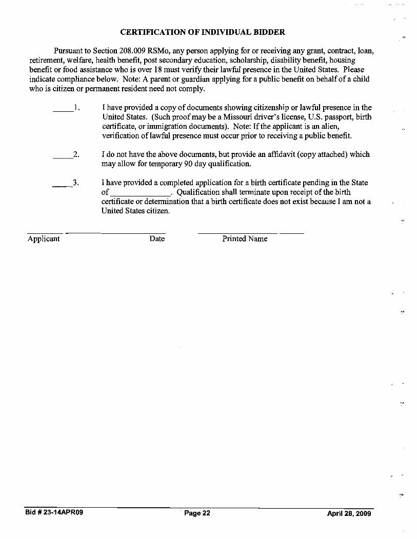
CERTIFICATION OF INDIVIDUAL BIDDER
Pursuant to Section 208.009 RSMo, any person applying for or receiving any grant, contract, loan, retirement, welfare, health benefit, post secondary education, scholarship, disability benefit, housing benefit or food assistance who is over 18 must verifl their lawful presence in the United States. Please indicate compliance below. Note: A parent or guardian applying for a public benefit on behalf of a child who is citizen or permanent resident need not comply.
1. I have provided a copy of documents showing citizenship or lawful presence in the United States. (Such proof may be a Missouri driver's license, U.S. passport, birth certificate, or immigration documents). Note: If the applicant is an alien, verification of lawful presence must occur prior to receiving a public benefit.
2. I do not have the above documents, but provide an affidavit (copy attached) which may allow for temporary 90 day qualification.
3. I have provided a completed application for a birth certificate pending in the State of . Qualification shall terminate upon receipt of the birth certificate or determination that a birth certificate does not exist because I am not a United States citizen.
Applicant Date Printed Name
Bid # 23-14APR09 Page 22 April 28, 2009

AFFIDAVIT (Only Required for Individual Bidder Certification Option #2)
State of Missouri ) )SS.
County of )
I, the undersigned, being at least eighteen years of age, swear upon my oath that I am either a United States citizen or am classified by the United States government as being lawfully admitted for permanent residence.
Date Signature
Social Security Number Printed Name or Other Federal I.D. Number
On the date above written appeared before me and swore that the facts contained in the foregoing affidavit are true according to hisher best knowledge, information and belief.
Notary Public
My Commission Expires:
Bid # 23-14APR09 Page 23 April 28, 2009

Boone County Purchasing 601 E. Walnut, Room 209
Columbia, MO 6520 1 Standard Terms and Conditions
Tyson Boldan, Buyer Phone: (573) 886-4392- Fax (573) 886-4390
1. Responses shall include all charges for packing, delivery, installation, etc., (unless otherwise specified) to the Boone County Department identified in the Request for Quotation andlor Proposal.
2. The Boone County Commission has the right to accept or reject any part or parts of all bids, to waive technicalities, and to accept the offer the County Commission considers the most advantageous to the County. Boone County reserves the right to award this bid on an item-by-item basis, or an "all or none" basis, whichever is in the best interest of the County.
Bidders must use the bid forms provided for the purpose of submitting bids, must return the quotation and bid sheets comprised in this bid, give the unit price, extended totals, and sign the bid.
When products or materials of any particular producer or manufacturer are mentioned in our specifications, such products or materials are intended to be descriptive of type or quality and not restricted to those mentioned.
5. Do not include Federal Excise Tax or Sales and Use Taxes in bid process, as law exempts the County fiom them.
6. The delivery date shall be stated in definite terms, as it will be taken into consideration in awarding the bid.
7. The County Commission reserves the right to cancel all or any part of orders if delivery is not made or work is not started as guaranteed. In case of delay, the Contractor must notify the Purchasing Department.
8. In case of default by the Contractor, the County of Boone will procure the articles or services fiom other sources and hold the Bidder responsible for any excess cost occasioned thereby.
9. Failure to deliver as guaranteed shall disqualify Bidder fiom future bidding.
10. Prices must be as stated in units of quantity specified, and must be firm. Bids qualified by escalator clauses may not be considered unless specified in the bid specifications.
11. No bid transmitted by fax machine will be accepted.
12. The County of Boone, Missouri expressly denies responsibility for, or ownership of any item purchased until same is delivered to the County and is accepted by the County.
13. The County reserves the right to award to one or multiple respondents. The County also reserves the right to not award any item or group of items if the services can be obtained fiom a state or other governmental entities contract under more favorable terms.
-Bid # 23-14APR09 Page 24 April 28,2009
z.z

Boone County Purchasing 60 1 E. Walnut, Room 209
Columbia,MO 65201 "NoBid" Response Form
Tyson Boldan, Buyer (573) 886-4392- Fax: (573) 886-4390
"NO BID RESPONSE FORM"
NOTE: COMPLETE AND RETURN THIS FORM ONLY IF YOU DO NOT WANT TO SUBMIT A BID
If you do not wish to respond to this bid request, but would like to remain on the Boone County vendor list for this service/commodit~,please remove form and return to the Purchasing Department by mail or fax.
If you would like to FAX this 'Wo Bid" Response Form to our office, the FAX number is (573) 886-4390.
Bid: 23-14APR09 - Sheriff's Department Emergency Equipment
Business Name:
Address:
Telephone:
Contact:
Date:
Bid # 23-14APR09 Page 25 April 28, 2009

Commission Order # 2-26-2 0 9
PURCHASE AGREEMENT FOR
Sheriffs Department Emergency Equipment Term and Supply
THIS AGREEMENT dated the q R day of .hhg 2009 is made between Boone County, Missouri, a political subdivision of the State of Mis uri through the Boone County Commission, herein "County" and Ka-Comm., Inc. herein "Contractor".
IN CONSIDERATIONof the parties performance of the respective obligations contained herein, the parties agree as follows:
1. Contract Documents - This agreement shall consist of this Purchase Agreement for Sheriffs Department Emergency Equipment Term and Supply, County of Boone Request for Bid number 23-14APR09, Introduction and General Conditions of Bidding, Primary Specifications, Response Presentation and Review, the un-executed Response Form, Standard Terms and Conditions, any applicable addenda, as well as the Contractor's bid response dated March 03,2009 and executed by Jim Dehm, on behalf of the Contractor. All such documents shall constitute the contract documents, which are attached hereto and incorporated herein by reference. Service or product data, specification and literature submitted with bid response may be permanently maintained in the County Purchasing Office bid file for this bid if not attached. In the event of conflict between any of the foregoing documents, the Introduction and General Conditions of Bidding, Primary Specifications, Response Presentation and Review, the un-executed Response Form, Standard Terms and Conditions, and any applicable addenda shall prevail and control over the Contractor's bid response.
2. Contract Duration - This agreement shall commence on the date of award and extend through June 30,2010 subject to the provisions for termination specified below. This agreement may be extended beyond the expiration date by the order of the county for three (3) additional one (1) year periods subject to the pricing clauses in the contractor's RFB response and thereafter on a month to month basis in the event the County is unable to re-bid andlor award a new contract prior to the expiration date after exercising diligent efforts to do so or not.
3. Purchase - The County agrees to purchase from the Contractor and the Contractor agrees to supply the County with the following items per the bid specifications and responded to on the Response Form:
4.7.1.1. Federal Signal Legend Light bar LGD45H-0013 4.7.1.2. Federal Signal SS2000SM-SD Smart Siren
These items shall conform with the contract documents for the prices set forth in the Contractor's bid response, as needed and as ordered by County.
4. Billing and Payment - All billing shall be invoiced to the Boone County Sheriffs Department and billings may only include the prices listed in the Contractor's bid response. IVo additional fees or extra services not included in the bid response or taxes shall be included as additional charges in excess of the charges in the Contractor's bid response to the specifications. The County agrees to pay all correct monthly invoices within thirty days of receipt; Contractor agrees to honor any cash or prompt payment discounts offered in its bid response if county makes payment as provided therein. In the event of a billing dispute, the County reserves the right to withhold payment on the disputed amount; in the event the billing dispute is resolved in favor of the Contractor, the County agrees to pay interest at a rate of 9% per annurn on disputed amounts withheld commencing from the last date that payment was due.
6. Binding Effect - This agreement shall be binding upon the parties hereto and their successors and assigns for so long as this agreement remains in full force and effect.
An M i a t i v e ActionlEqual Opportunity Institution

Commission Order #
7. Entire Agreement - This agreement constitutes the entire agreement between the parties and supersedes any prior negotiations, written or verbal, and any other bid or bid specification or contractual agreement. This agreement may only be amended by a signed writing executed with the same formality as this agreement.
8. Termination - This agreement may be terminated by the County upon thirty days advance written notice for any of the following reasons or under any of the following circumstances:
a. County may terminate this agreement due to material breach of any term or condition of this agreement, or
b. County may terminate this agreement if in the opinion of the Boone County Commission if delivery of products are delayed or products delivered are not in conformity with bidding specifications or variances authorized by County, or
c. If appropriations are not made available and budgeted for any calendar year.
IN WITNESS WHEREOF the parties through their duly authorized representatives have executed this agreement on the day and year first above whtten.
KA-COMM., INC. BOONE COUNTY, MISSOURI
by: Boone County commission/
L/title .5-5r&P
ATTEST:
,wendy S. ~ o r e d County ~ l e r l (
AUDITOR CERTIFICATION In accordance with RSMo 50.660, I hereby certify that a sufficient unencumbered appropriation balance exists and is available to satisfy the obligation(s) arising from this contract. (Note: Certification of this contract is not required if the terms of this contract do not create a measurable county obligation at this time.)
Department: 125 11290 1125.50 Account: 91 300192300 TedSupply
An Affirmative Action/Equal Opportunity Institution

4.1. CompanyName: KA- Comn.,Tnv,-41. Addrces:
43. CstyJZp: 199/5E A I F - ~ S /6/k .57k!C7
4.4. PhoneNumbsh?) 7L+ 5??/+'
45. FaxNtPmba:
4.6. FuJ6nl Tax ID:
4.6.1. 94 Corporation ( ) Pamenhip -Name ( ) I n d i v i d u e ~ e t o m h i p -IndividualNafm ( ) - ( s M l
4.7. See BldReqo~eShaer
4.7.4. Total e
1 Description
4.73. YARIDySMAF
.. 3,i o a . 6 -
Bid# 23-t4APR08 Pa@8 18 ~ 2 7 . 2 0 0 9
- -
4.7.3.1. 4.7.3.2. 4.7.33. 4.7.3.4.
I I
~ o m c~hsrmsl~ m g ~ n g~amaa 1s & ~ h SwndOff S i g d rear fksbamcdel BIFBSSN-P(or aqoivaknt) ( $ ,,,,,bRcar Plisona scatfor UW)9Dad- k e r It e r r r r
PrisonsParlition for 2009 Dodgo Chmgm I $ r o c 4s

4.12. Theut~Ier91gnalo~to 8naiaba d ddivmtboaniclw msavicos .sspeoitiedat thaprimandLmmr s c a o c d a n d m s t r i e t ~ w i t b d ~ q u h s m m ( s ~ e d & t h e ~ p t f w B i d h b m n r r s d andundsrstood,and allofwhichsno d eparl of thLorda.

CatiaclltioaRCgading Dcbarmmt, Suspension,hligi'bilitydVohmlaryE*cbion
LoamTim C o d T-ions
(2) Where the proapativs nqicnt of PcdsrolarslImk-8flu& lsunrbk lo M y m my of the inchia dfication, suchproqxzthmp a r t i o i shall n ~ anbcxplaoetian to (bi4 poposaL
Date
Bld 1)23-14APROB -a Mafch27,ZOOg - rl
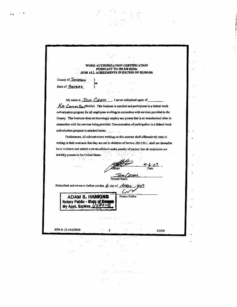
WORK AUTFIORlZATION CERTIFICATION PURSUANT TO U15530RSMo
(IFOR ALL AGREEMENTS INEXC- OFSS,000.00)
Countyof Z O W ~ V * ~1 bs
Stateof C ( A ~ K A S 1
. I am an authorized agent of
1(A- &&@idder). This Wasis enrolled and participates in a federal work
authorizaficm program for all employees w a gm wnneotionwith senices providedto the
Camty. This busineaa dbesnot loaowinglyemploy my person that ia an unauthorizedalim in
cmmtion with the servicesbeingprovided.Lhaunentation of participation in a federal work
authorizationprogram is attachedhareto.
Furthennore, all subcontractors working on this contract shall a&matively state in
writhg iu theirconlracts that they are not in violation of Semion 285.530.1, shallnot thoreafter
be in violation and submita swornafIidavitunderpenalty ofMury that all emplow are
lawfully present in the United States.
My name is m ~ ~ r n
Printed Nm-e
Subscribed nnd sworn to beforeme this day of
b ~ ~ E $ 2 ! 2 z ~
RFB #: 23-14APRC9 2 i
4/2/09

OFPEROR has examined copy of Addmhm#1 to f o r m # S14APR09 -E m m ~ SberWr Eqdpcnt. mx&tofwhich isM y d w l * e d :
CompanyName: X/~*[bmrt,,.SAC ~dLiIw8: / 9 9 / 5 ~,t~..g/6/# d7~'887
&!A&%#! A3 &&I Pax Number. 9/3-%9*%M
~ u b r i z e dmmmtati~~ e dN-:

Request for Proposal #: 23-14APR09 -Emergency Sheriff's Equipment
ADDENDUM #1- Issued April 2,2009 This addendum is issued in accordance with the Introduction and General Information of Bidding in the Request for Proposal and is hereby incorporated into and made a part of the Request for Proposal Documents. Offerors are reminded that receipt of this addendum must be acknowledged and submitted with Offeror's Response/Pricing Page.
Specifications for the above noted Request for Proposal and the work covered thereby are herein modified as follows, and except as set forth herein, otherwise remain unchanged and in full force and effect:
1. Add the attached Work Authorization Certification sheet to the bid documents:
RFB #: 23-14APR09 1 4/28/09

WORK AUTHORIZATION CERTIFICATION PURSUANT TO 285.530 RSMo
(FOR ALL AGREEMENTS IN EXCESS OF $5,000.00)
County of 1 1ss
state of &&/j )
My name is .%n? / 3 & ~ - . I am an authorized agent of
, (Bidder). This business is enrolled and participates in a federal work
authorization program for all employees working in connection with services provided to the
County. This business does not knowingly employ any person that is an unauthorized alien in
connection with the services being provided. Documentation of participation in a federal work
authorization program is attached hereto.
Furthermore, all subcontractors working on thls contract shall affirmatively state in
writing in their contracts that they are not in violation of Section 285.530.1, shall not thereafter
be in violation and submit a sworn affidavit under penalty of perjury that all employees are
lawfully present in the United States.
r m r A R V P w l J c - ~ a f K M D I s KIMBERLY M. RUDER
-Printed Name
Subscribed and sworn to before me this J.rh day of 34
~ o t a r ?Public
RFB #: 23-14APR09 2 4/28/09

By: Tyson Boldan, Buyer
OFFEROR has examined copy of Addendum #1 to Request for Proposal # 23-14APR09 -Emergency Sheriff's Equipment, receipt of which is hereby acknowledged:
Company Name:
Address:
Phone Number: Fax Number:
Authorized Representative Signature: Date:
Authorized Representative Printed Name:
RFB #: 23-14APR09 3 4/28/09

Boone County Purchasing
Request for Bid (RFB) 601 E. Walnut, Room 209
Tyson Boldan, Buyer Phone: (573) 886-4392 -Fax: (573) 886-4390
Email:
Bid Data Bid Number: 23-14APR09
Commodity Title: Sheriff's Department Emergency Equipment
DIRECT BID FORMAT OR SUBMISSION QUESTIONS TO THE PURCHASING DEPARTMENT
Bid Submission Address and Deadline Day / Date: TUESDAY APRIL 14,2009
Time: 1 :30 P.M. (Bids received after this time will be returned unopened) Location 1 Mail Address: Boone County Purchasing Department
Boone County Johnson Building 601 E. Walnut, Room 209 Columbia, MO 65201
Directions: The Johnson Building is located on the Northeast corner at 6~ Street and Walnut Street. Enter the building f?om the East Side. Wheel chair accessible entrance is available on the West side of the building.
Bid Opening Day / Date: TUESDAY APRIL 14,2009
Time: 1 :30 P.M. C.S.T. Location / Address: Boone County Johnson Building Conference Room
601 E. Walnut, Room 213 Columbia, MO 65201
Bid Contents 1 .O: Introduction and General Conditions of Bidding 2.0: Primary Specifications 3.0: Response Presentation and Review 4.0: Response Form
Work Authorization Certification Debarment Form Certification of Individual Bidder Individual Bidder Affidavit Standard Terms and Conditions "No Bid" Response Form
Bid # 23-14APR09 Page 1 April 28, 2009

Countv o f Boone Purchasing Deoartment 1. Introduction and General Conditions of Bidding
1.1. INVITATION - The County of Boone, through its Purchasing Department, invites responses, which offer to provide the goods andlor services identified on the title page, and described in greater detail in Section 2.
1.2. DEFINITIONS 1.2.1. County - This term refers to the County of Boone, a duly organized public entity. It may also be used as a
pronoun for various subsets of the County organization, including, as the context will indicate: Purchasing - The Purchasing Department, including its Purchasing Director and staff. Department(s) or Ofice(s) - The County Department(s) or Office(s) for which this Bid is prepared, and which will be the end user(s) of the goods andor services sought. Designee - The County employee(s) assigned as your primary contact(s) for interaction regarding Contract performance.
1.2.2. Bidder I Contractor I Supplier - These terms refer generally to businesses having some sort of relationship to or with Boone County. The term may apply differently to different classes of entities, as the context will indicate. Bidder - Any business entity submitting a response to this Bid. Suppliers, which may be invited to respond, or which express interest in this bid, but which do not submit a response, have no obligations with respect to the bid requirements. Contractor - The Bidder whose response to this bid is found by Purchasing to meet the best interests of the County. The Contractor will be selected for award, and will enter into a Contract for provision of the goods andlor services described in the Bid. Supplier - All business(s) entities which may provide the subject goods andor services.
1.2.3. Bid - This entire document, including attachments. A Bid may be used to solicit various kinds of information. The kind of information this Bid seeks is indicated by the title appearing at the top of the first page. A "Request for Bid" is used when the need is well defined. A "Request for Proposal" is used when the County will consider solutions, which may vary significantly fiom each other or fiom the County's initial expectations.
1.2.4. Response - The written, sealed document submitted according to the Bid instructions. 1.3. BID CLARIFICATION - Questions regarding this Bid should be directed in writing, preferably by fax or e-
mail, to the Purchasing Department. Answers, citing the question asked but not identifyrng the questioner, will be distributed simultaneously to all known prospective Bidders. Note: Written requirements in the Bid or its Amendments are binding, but any oral communications between County and Bidder are not.
1.3.1. Bidder Responsibility - The Bidder is expected to be thoroughly familiar with all specifications and requirements of this Bid. Bidders' failure or omission to examine any relevant form, article, site or document will not relieve them fiom any obligation regarding this Bid. By submitting a Response, Bidder is presumed to concur with all terms, conditions and specifications of this Bid.
1.3.2. Bid Amendment - If it becomes evident that this Bid must be amended, the Purchasing Department will issue a formal written Amendment to all known prospective Bidders. If necessary, a new due date will be established.
1.4. AWARD - Award will be made to the Bidder(s) whose offer(s) provide the greatest value to the County fiom the standpoint of suitability to purpose, quality, service, previous experience, price, lifecycle cost, ability to deliver, or for any other reason deemed by Purchasing to be in the best interest of the County. Thus, the result will not be determined by price alone. The County will be seeking the least costly outcome that meets the County needs as interpreted by the County.
1.5. CONTRACT EXECUTION - This Bid and the Contractor's Response will be made part of any resultant Contract and will be incorporated in the Contract as set forth, verbatim.
1.5.1. Precedence- In the event of contradictions or conflicts between the provisions of the documents comprising this Contract, they will be resolved by giving precedence in the following order: 1) the provisions of the Contract (as it may be amended); 2) the provisions of the Bid; 3) the provisions of the Bidder's Response.
1.6. CONTRACT PERIOD - Any Term and Supply Contract resulting from this Bid will have an initial term fiom date of award through June 30,20 10 with three (3) additional one-year periods following expiration of the first contract period.
1.7. COMPLIANCE WITH STANDARD TERMS AND CONDITIONS - Bidder agrees to be bound by the County's standard "boilerplate" terms and conditions for Contracts, a sample of which is attached to this Bid.
Bid # 23-14APR09 Page 2 April 28, 2009

Countv o f Boone Purchasina Department 2. Primary Specifications
2.1. ITEMS TO BE PROVIDED -Emergency vehicle equipment items, light bars, and sirens. 2.1.1. Contract Documents -The successful bidder(s) shall be obligated to enter into a written contract with the
County within thtrty (30) days of award on contract forms provided by the County. If bidders desire to contract under their own written agreement, any such proposed agreement shall be submitted in blank form with their bid. The County reserves the right to modify any proposed form agreement or withdraw its award to a successful bidder if any proposed agreement contains terms and conditions inconsistent with its bid or are unacceptable to County legal counsel.
2.1.2. Contract Extension -The County Purchasing Director may exercise the option to extend the contract on a month-to-month basis for a maximum of 6 months fiom the date of termination if it is deemed to be in the best interest of Boone County.
2.2. Federal Signal Corporation Legend LED Lightbar (including the HotFootTM Mounting System) 2.2.1. This specification describes the minimum requirements for a low profile lightbar utilizing LED technology for
emergency vehicles manufactured by Federal Signal Corporation. The lightbar system shall utilize Solaris S2 reflector LED based technology and Reliable Onboard Circuitry (ROC) manufacturing design. The lightbar system must include an upper-level (primary) and lower-level (secondary) light source. Single-level lightbar warning systems shall not be acceptable.
2.3. PRIMARY WARNING 2.3.1. Light emitting diode (LED) light heads shall consist of Solaris S2 reflector modules utilizing high output LED
technology. Each Solaris S2 module shall use a compound-curve and polished reflector design and shall contain three or six diodes. Solaris S2 reflector modules shall be available in red, blue, white, and amber LEDs. Each lightbar shall contain a total of thvty Solaris S2 reflector modules. A total of eleven red Solaris S2 modules, eleven blue Solaris S2 modules, four amber Solaris S2 modules, and four white Solaris S2 modules (TDIAL) shall be included. The maximum total number of Gen 3 lamp diodes shall be one hundred --eight (1 3 8).
2.3.2. Reliable onboard circuitry technologies shall be utilized. Legend lightbar design shall utilize surface mounted LEDs projecting downward into the Solaris S2 reflector assemblies. ROC technology shall use microprocessor controls to provide a total of twenty-six user-selectable flash patterns, including an intersection mode, two test patterns and a low power 'dim' mode. ROC circuitry shall be field replaceable and shall meet the approval of the following specifications: SAE 11 13/41 RFI and SAE J845. No exceptions shall be allowed.
2.3.3. The Legend lightbar shall function with three prioritized modes of operation. Mode 3 shall be the highest priority and shall ovemde both Mode 2 and Mode 1. Mode 2 shall ovemde Mode 1. Each of the three modes will provide preset (default SAE J845/CCR, Title 13) flash patterns that can be activated for various stages of the emergency vehicle's warning light levels of operation. A total of twenty-six flash patterns are available for mode selections.
2.3.4. Intersection flash mode of operation: The lightbar shall provide a high activity pattern that attracts attention to the vehicle as it approaches an intersection. Intersection operation shall be able to be controlled by three selected options including Power On-Off function, TAPII (push-onlpush-off) by using a momentary contact switch or horn ring button or 8-second timer activation.
2'3'5 FrontRear Cutoff or Enable function: The lightbar shall be able to provide a fiontlrear cutoff and fiontlrear enable function. Frontlrear cutoff is controlled by applying 12 VDC to supplied controlled wires. Frontlrear enable activates the LED modules when +Bat is applied to their control wires. This h c t i o n allows the lightbar to be custom programmed to meet a wide range of departmental needs and installed light controls.
2.3.6 The Legend lightbar shall be able to operate in the low power mode if desired. The lightbar shall be capable of dimming the main bar LEDs approximately 50% to prevent blinding of approaching vehcles. The low power function shall only operate in Mode 1 or Mode 2 levels. It is disabled when the lightbar is turned off or switched to another flash pattern, including Mode 3 or the intersection mode level. Lightbars that dim in level 3 or during the pursuit mode shall not be accepted, no exceptions will be allowed.
2.3.7 The lightbar shall have zero standby current (mA) while it is not in operation. This helps reduce vehicle electrical draw whle the car is not in use.
2.4. HOUSING -BODY 2.4.1. The solid aluminum extrusion shall be of a 118" minimum thickness design to provide strength and durability
without excessive weight. The mounting feet and bases for light mechanisms attach directly to the extrusion's integrated mounting channel which provides a well-secured mounting platform.
2.4.2. The lightbar housings shall be molded polycarbonate for durability and strength. Both domes shall be secured to the extruded aluminum fiame by use of four barrel nut with O-ring seals and bolt assemblies. A lip seal gasket shall be around all external perimeters to provide a weatherproof seal. The upper level domes must
Bid # 23-14APR09 Page 3 April 28,2009

incorporate a honeycomb-molded design to maximize strength and reinforcement for the internal lightbar components from hail and unforeseen impact. The upper level domes shall be clear (driver), and clear (passenger). The lower level domes shall be clear. Lower housing shall be a smooth one piece molded polycarbonate construction. No vertical gaskets, multi segmented lenses or exterior mounted LED modules are acceptable. Lower housing should have a minimum of (8) one way vent plugs that allows condensation to be vented during changing environment conditions. Domes shall mount on top of the lower housings with barrel nuts with O-ring seals. Dome mounting clips and standard bolts are not acceptable. SERIAL INTERFACE MODULE The serial interface module is the device used to communicate with the Legend lightbar. Each lightbar shall be controlled via a standard RS485 bus connection with protocols based upon SAE standards 51708 and 51587. A serial interface module shall be included (FS model #Z8583446) that transitions h m the RJ-style connection to the 24-conductor control link cable harness. Lightbar hook-up shall require only a 10-ga power cable, a 10-ga ground cable, and a 25' snap-in CAT 5 communication cable. Both the 10-ga power and the 10-ga ground cables shall measure twenty-one feet in length -no exceptions. The lightbar shall be capable of being removed from the vehicle without disassembly of the vehicle's emergency light controller's wiring system for ease of service or repair. LOWER-LEVELISECONDARY WARNING An integral component of the lightbar shall be the lower-level HotFoot mounting and light system. The HotFoot design shall serve as both a secondary warning light source and as a roof mounting system. Each mounting foot assembly shall include four LED modules. The HotFoot shall be constructed of glass-filled nylon and is available in black. The LED housings shall be made of die cast aluminum and the LED lenses shall be clear polycarbonate plastic.
The mounting foot light assembly shall contain two LED takedown modules, and shall consist of six GEN I11 high brightness LEDs. LED takedown light assemblies shall be adjustable horizontally by positioning them straight, at 45 degrees or at 90 degrees. Each position has +I-10 degrees of adjustment.
The mounting foot light assembly shall contain two LED alley modules, and shall consist of six GEN I11 high brightness LEDs. LED alley lights shall be adjustable horizontally by positioning them straight, at 45 degrees or at 90 degrees. Each position has +I- 10 degrees of adjustment.
As a convenience to the end user installer, for shipping purposes, and to further aid in the speed of installation, the HotFoot mounting legs will be installed to the base extrusion of the lightbar at a preset distance apart.
SIGNALMASTER A six-lamp LED SignalMaster traffic management device shall be built into the lightbar and standard for the Legend. Light heads shall consist of six Solaris S2 reflector modules.
The Legend lightbar shall be configured at the factory for 'external' SignalMaster control. When used with the appropriate (optional) SignalMaster controller, this device shall produce three distinct signals: left arrow sweep, right arrow sweep, and center arrow out and user selectable warning patterns.
The Legend lightbar can be configured for 'internal' SignalMaster control operation. In this mode, an external SignalMaster controller is not required. 12V applied to the specified control lead shall activate the lightbar's internal SignalMaster controller. Internal operation functions shall include: Left, Center, Right, Warn 1 : Outer LEDs alternate, Warn 2: Two outer LEDs alternate, Warn 3: Outer LEDs and two LEDs alternate, Warn 4: Outer LEDs and two inner LEDs flash, then the LEDs between the inner and outer LEDs; and Fast operates the selected pattern 50% faster. When the lightbar is operating in any of the three priority flashing modes, all SignalMaster modules shall emulate the selected flash patterns. When the operator activates the SignalMaster, the directional warning patterns shall ovemde any other activity in that portion of the lightbar. Lightbars that are not capable of this feature shall not be accepted.
MOUNTING BRACKETS
A hook-on mounting bracket with stainless steel hardware must be included and be compatible for vehicles with or without rain gutters. Mounting legs may be adjusted by the installer to meet a variety of roof width requirements of the specified vehicle. Three pair of rubber mounting pads shall be included and vary in height: short, medium, and tall. Mounting pads can be installed to determine the overall height of the lightbar off the roof of the vehicle and can compensate for various roof pitches and slope angle adjustments.
ELECTRICAL
Bid # 23-14APR09 Page 4 April 28, 2009
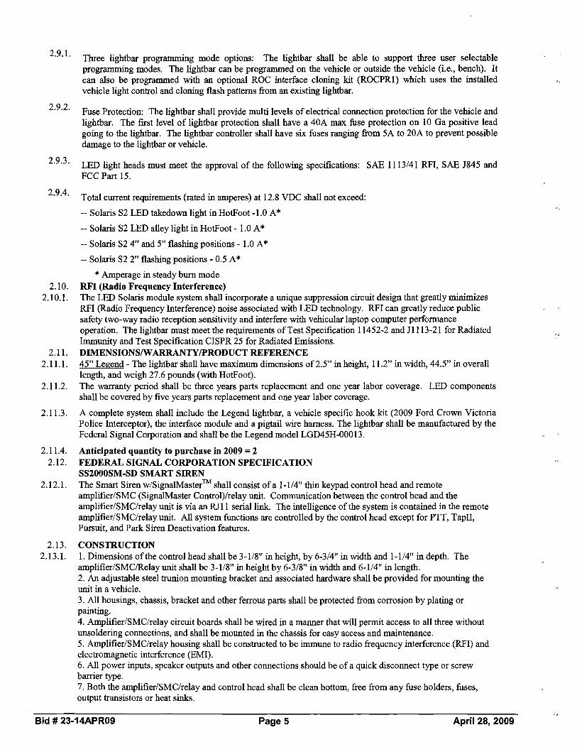
Three lightbar programming mode options: The lightbar shall be able to support three user selectable programming modes. The lightbar can be programmed on the vehicle or outside the vehicle (i.e., bench). It can also be programmed with an optional ROC interface cloning kit (ROCPRI) which uses the installed vehicle light control and cloning flash patterns fiom an existing lightbar.
Fuse Protection: The lightbar shall provide multi levels of electrical connection protection for the vehicle and lightbar. The first level of lightbar protection shall have a 40A max fuse protection on 10 Ga positive lead going to the lightbar. The lightbar controller shall have six fuses ranging fiom 5A to 20A to prevent possible damage to the lightbar or vehicle.
LED light heads must meet the approval of the following specifications: SAE 11 1314 1 RFI, SAE J845 and FCC Part 15.
Total current requirements (rated in amperes) at 12.8 VDC shall not exceed:
-- Solaris S2 LED takedown light in HotFoot -1.0 A*
-- Solaris S2 LED alley light in HotFoot - 1.0 A*
-- Solaris S2 4" and 5" flashing positions - 1.0 A*
-- Solaris S2 2" flashing positions - 0.5 A*
* Amperage in steady burn mode RFI (Radio Frequency Interference) The LED Solaris module system shall incorporate a unique suppression circuit design that greatly minimizes RFI (Radio Frequency Interference) noise associated with LED technology. RFI can greatly reduce public safety two-way radio reception sensitivity and interfere with vehicular laptop computer performance operation. The lightbar must meet the requirements of Test Specification 1 1452-2 and J1113-21 for Radiated Immunity and Test Specification CISPR 25 for Radiated Emissions. DIMENSIONS/WARRANTY/PRODUCTREFERENCE 45" Legend - The lightbar shall have maximum dimensions of 2.5" in height, 1 1.2" in width, 44.5" in overall length, and weigh 27.6 pounds (with HotFoot). The warranty period shall be three years parts replacement and one year labor coverage. LED components shall be covered by five years parts replacement and one year labor coverage.
A complete system shall include the Legend lightbar, a vehicle specific hook kit (2009 Ford Crown Victoria Police Interceptor), the interface module and a pigtail wire harness. The lightbar shall be manufactured by the Federal Signal Corporation and shall be the Legend model LGD45H-00013.
Anticipated quantity to purchase in 2009 =2 FEDERAL SIGNAL CORPORATION SPECIFICATION SS2000SM-SD SMART SIREN The Smart Siren w1signalMasterTM shall consist of a 1-114" thin keypad control head and remote amplifier1SMC (SignalMaster Contro1)lrelay unit. Communication between the control head and the amplifierlSMC1relay unit is via an RJ11 serial Imk. The intelligence of the system is contained in the remote amplifierlSMC1relay unit. All system functions are controlled by the control head except for PIIT, TapII, Pursuit, and Park Siren Deactivation features.
CONSTRUCTION 1. Dimensions of the control head shall be 3-118" in height, by 6-314" in width and 1-114" in depth. The amplifier/SMC/Relay unit shall be 3-118" in height by 6-318" in width and 6-114" in length. 2. An adjustable steel trunion mounting bracket and associated hardware shall be provided for mounting the unit in a vehcle. 3. All housings, chassis, bracket and other ferrous parts shall be protected from corrosion by plating or painting. 4. AmplifierISMClrelay circuit boards shall be wired in a manner that will permit access to all three without unsoldering connections, and shall be mounted in the chassis for easy access and maintenance. 5. AmplifierlSMClrelay housing shall be constructed to be immune to radio frequency interference (RFI) and electromagnetic interference (EMI). 6. All power inputs, speaker outputs and other connections should be of a quick disconnect type or screw barrier type. 7. Both the amplifier/SMClrelay and control head shall be clean bottom, free from any fuse holders, fuses, output transistors or heat sinks.
Bid # 23-14APR09 Page 5 April 28, 2009

8. A separate control head allows the amplifierlSMC1relay unit to be remotely mounted. 9. The control head shall have the capability of interchangeable custom legends for designating functions. A sheet of applicable h c t i o n legends shall be supplied. 10.All connections to the barrier strip on the rear of the amplifierlSMC1relay unit housing must be of a clamp type, not requiring additional crimped connectors.
11. Connection to the control head from the amplifierISMClrelay unit shall be via a RJ11 telephone cable with telephone type connectors. Connections for ignition, ground, horn ring, horn, radio rebroadcast, pursuit and speaker must be via a twelve-pin Molex type connector. Connection to the signalMasterTM shall be via a two- piece, quick disconnect terminal block. 12.Terminals shall be provided at the rear of amplifier the ISMCIrelay unit for a convenient junction point for the light and auxiliary functions.
2.14. ELECTRICAL 2.14.1. 1. The unit shall be designed for negative ground vehicles. Normal operating voltage shall be 1 1.0 to 1 6.0
VDC. 2. The unit shall be protected by a 20-ampere fuse. 3. The electronic siren circuit shall have reverse polarity protection to insure that damage shall not occur to the siren, except possible fuse replacement should the polarity of the supply voltage be accidentally reversed. 4. Power shall be controlled through the positive ignition input. 5. Volume control for radio rebroadcast and PA should be located in the amplifierlSMC1relay unit and be preset. 6. The control head unit shall be backlit with LED indicators. Intensity of the LED'S may be adjusted or turned off with the backlighting. 7. The unit shall have relays on a separate printed circuit board. One output rated at 40 amperes, two at 20 amperes and five at 10 amperes. 8. Fuses on the relay and SMC boards shall be of the automotive blade type. The control head shall also to be protected by a fuse in the amplifierISMClrelay unit. The Smart Siren System shall contain a total of eleven fuses. 9. The remote amplifier shall have a 114" diameter phone jack for the optional transistorized noise canceling microphone (MNCT) andlor optional microphone extension kit (RMK).
2.15. PERFORMANCE 2.15.1. 1. The Wail, Yelp, Priority, and Hi-Lo frequency shall be a nominal 700HZ to 1500HZ.
2. The Wail tone shall cycle at a nominal rate of 12 cycles per minute. 3. The Yelp tone shall cycle at a nominal rate of 180 cycles per minute.
4. The Hi-Lo tone shall cycle at a nominal rate of 60 cycles per minute. 5. The Priority tone, AIH tone, and manual siren tones are available. 6. Siren output voltage: 64V peak-to-peak nominal at 100W tap with 1 1-ohm load. 7. Audio output power (PA and radio): 45W RMS nominal with 1 1-ohm load. 8. Audio harmonic distortion less than 10% of 1000 HZ reference at 13.6V battery from 5 watts through 45 watts. 9. Operating temperature range shall be 30 degrees to +65 degrees Celsius. 10.The signal~asterTM controller output drive maximum capability is eight 27-watt lamps. It can be configured to control six. 11. The ~ i g n a l ~ a s t e r ~ ~ normal directional flash rate is 35 patterns per minute. The normal warn flash rate is 60 patterns per minute. The fast directional flash rate is 60 patterns per minute. The fast warn flash rate is 95 patterns per minute.
2.16. FORMAT 2.16.1. 1. The control head with the four (4) position slide switch and seventeen (17) push on - push off switches shall
provide selection and programming of the following functions: a) Programming of the various features is performed from the switches on the control head, without disassembly or removal of the unit from its mounting location. b) The !OJ row of the control head switches operates the SignalMaster functions. The middle row of control head switches operates the siren functions. The bottom row of the control head switches and the slide switch are all capable of being programmed to control the emergency vehicle's warning lights, SignalMaster patterns, and auxiliary functions. c) The slide switch positions located on the bottom row of the control head can be programmed to activate one or more light functions. Mode 1,2 or 3 of the slide switch can be programmed to automatically generate a siren tone, pre-selected upon power up or manually selected. The siren tones can also be programmed to generate a siren tone independent of the slide switch.
Bid # 23-14APR09 Page 6 April 28, 2009

Each slide switch position can be configured to operate any combination of all eight relays plus Key 1 1, Horn Ring Transfer, Siren Enable, and SignalMaster WARN patterns. d) ,The five auxiliary switches can be programmed to be push-odpush-off, momentary or eight-second timer. All eight-second timers can be set-up as a security timer (two switches need to be pressed for timer to operate). The security timer is especially effective when actuating shotgun locks.
e) The horn ring can be programmed to activate in Modes 1,2 or 3, or can be independently controlled using a control head switch. Smart Siren technology allows the operator to select the siren sound (Wail, Yelp, Hi-Lo, Priority) available at "power up" as well as via the horn ring. Horn ring can be programmed to activate manual siren or air horn. f) Adhesive backed function legends identify the switches. A legend card consisting of one hundred and forty (140) legends shall be supplied with each unit. No disassembly is required to install the legends. g) Radio rebroadcast provides amplification of incoming radio messages through the outside loudspeaker. h) Public address controls optional FN module to provide PA operations or can be configured to operate the horn ring transfer. i) Wail provides a continuous cycling of the siren tone frequency at a rate of 12 nominal cycles per minute. j) Yelp provides a continuous cycling of the siren tone frequency at a nominal rate of 180 cycles per minute. k) Hi-Lo provides an alternating high and low tone at a nominal rate of 60 cycles per minute. 1) The Priority tone can be programmed in place of the Hi-Lo tone. m) Auxiliary remote input allows simple push button activatiodde-activation bursuit) of mode 3, or toggle between modes 2 and 3, or can be configured to deactivate the siren when in Park. 2. Public address shall ovemde siren functions upon activation of the microphone. 3. The unit shall have a momentary push button on the control head to operate the air horn tone. 4. The unit shall have a momentary push button on the control head, which will operate manual siren. Manual siren shall also have capability to operate Tap I1 feature. 5. The control head shall have rubberized push on push off switches, and a four-position slide switch. 6. The unit shall accept both positive and ground horn ring switch circuits without determining the polarity of the horn ring circuit, or changing any external or internal switches or internal wiring.
7. An "instant Yelp" or "instant Priority" option shall be available through the horn ring circuit when operating in the wail mode. Instant Yelp or Priority shall also have the capability of being programmed to revert back to Wail after eight seconds. 8. The Smart Siren shall be capable of operating 58, 100, andlor 200-watt vehicular siren speakers. 9. Relays sequence on and off to minimize power surges. 10. The programming mode can be disabled to prevent tampering. 1 1. The SignalMaster controller can be programmed to operate six lamp or eight lamp SignalMasters.
12. The SignalMaster can perform six directional patterns (left, right, center-out and the low power patterns of left right and center-out), four alternating warning patterns, and a fast version of all of the previous patterns.
2.17. WARRANTY & PRODUCT REFERENCE 2.17.1. The warranty period shall be three years parts and one-year labor coverage. The siren shall be the Federal
Signal Corporation model SS2000SM-SD, including the optional MNCT microphone and RMK cable kit.
2.17.2. Anticipated quantity to purchase in 2009 =2 2.189. Dodge Charger Emergency LightingISiren System Specifications (Whelen Products)
2.18.1. It is the department's intent to purchase the warning system from one vendor; therefore, all components must be made by one manufacturer. Bids for equipment fabricated by more than one manufacturer will be considered unacceptable. The emergency vehicle warning equipment must be manufactured by a single company and must contain the following equipment: 107UF8; I07LR8L; PEIMDOC08; FEDC06RR and FEDC06BR; LINZ6R and LINZ6B with (2) RBKT1; LAW2CC; CCSRN2 with CCMICXZO; (2) SA315P with (2) SAK18; IBDC06JJ, as described below.
2.18.2. SUPER-LED INTERIOR LIGHT BAR - INNER EDGE (FRONT) 2.18.3. 1. The device shall be housed in two individual heavy duty polycarbonate housings with a clear outer lens for
stealth look. Both units shall appear to be void of color until the Super-LED'S are turned on. Each unit must be supplied with mounting brackets for ease of mounting ip a 2009 DODGE CHARGER,one on the driver side, the other on the passenger side of the vehicle, and will be designed to fit snuggly to the windshield to prevent flash back into the passenger compartment. 2. Each housing shall contain four (4) Super-LED panels. Each LED must be a high intensity Generation 3.5 Super-LEDs (Light Emitting Diodes). Each housing must have four (4) lamps facing straight out of the housing and one (1) MR8 take-down light mounted in the inboard position [4 Red Driver Side I 4 Blue Passenger Side]. These LED'S shall have a life expectancy of at least 100,000 hours. Each LED segment
Bid # 23-14APR09 Page 7 April 28, 2009

- -
shall utilize a maximum of three (3) Super-LEDs. 3. Each light head lens shall cover a maximum of three (3) individual Super-LEDs (Generation 3.5) that are mounted in a straight row and have a life expectancy of at least 100,000 hours. Each unit shall have a linear lens on the outermost outboard position and must alternate sequentially with a TIR lens as you move toward the inboard position. Spare TIR and linear lenses must be provided so the end user or installer can customize the optics to meet requirements. 4. The maximum amperage draw in any mode shall be no more than .25 amps at 12.8 volts DC. The amp draw is critical because the unit is designed to be used in a parked vehicle with its ignition off for long periods of time. 5. Each unit must include one (1) MR8 take-down light, with flashing and steady-burn capability, located on the innermost inboard position, 6. The two-piece Inner Edge shall be connected by an interconnect cable connecting the dnver side unit to the passenger side (PS) unit. The PS unit shall have a 9 conductor, 18 gauge, 20 foot jacketed cable that allows or control of warning lights, Scan-Lock (24 flash patterns to choose from), synchronization feature, take-down lights, flashing take-down, and low power. Units that do not provide all of these features are unacceptable.
2.18.4. SUPER-LED INTERIOR LIGHT BAR -LNNER EDGE (REAR) 2.18.5. 1. The device shall be housed in a heavy duty polycarbonate housing with a clear outer lens for stealth look.
The unit shall appear to be void of color until the Super-LEDs are turned on. The unit must be supplied with mounting brackets for ease of mounting to the rear deck of a 2009 DODGE Charger. 2. The device shall be approximately 44 inches in length, 2.7 inches in height, and 6.3 inches in width; and be designed to fit snuggly to the rear window to reduce flash back into the passenger compartment. 3. The device shall contain a minimum of eight (8) Super Linear-LED panels [4 Red Driver Side 1 4 Blue Passenger Side]. The red and blue Super-LED'S shall be wired at time of installation as a warning light or a Traffic Advisor. Each panel shall utilize high intensity Generation 3.5 Super-LEDs (Light Emitting Diodes). The unit must have eight (8) wide angle Linear-LED modules facing straight out of the housing; Each Linear- LED module must produce significant light at a 45 degree angle for intersection protection/warning. These LED's shall have a life expectancy of at least 100,000 hours. Each LED light head shall utilize a maximum of six (6) Super-LED'S. 4. Each light head shall measure 5 inches long x 1.45 inches high and must contain a minimum of six (6) individual Super-LEDs (Generation 3.5) in a straight row with a single difiser panel mounted in front for maximum light output spread. The LEDs must have a life expectancy of at least 100,000 hours. Light modules that use mirrors to reflect light are not acceptable since they do not produce an even light spread. 5. The maximum amperage draw in any mode shall be no more than .5 amps at 12.8 volts DC. The amp draw is critical because the unit is designed to be used in a parked vehicle with its ignition off for long periods of time. 6. The Inner Edge shall include a 9 conductor, 18 gauge, 20 foot jacketed cable that allows or control of warning lights and Traffic Advisor functions (Left;Right; Split and Flash), Scan-Lock (multiple flash patterns to choose from) and Low power.
2.18.6. INTERFACE MODULE 2.18.7. The system must contain a Dodge Interface Module for a 2009 CHARGER. This module must be no greater
than 518 inches H x 2-314 inches W x 5-114 inches L (without mounting flange). The module must allow full access to a variety of options available with the CHARGER, by a simple plug and play. A few of these functions include flashing headlights and tail lights, radio input signal, fuel level status, and horn switch activation (among others).
2.18.8. SUPER-LED@ DODGE CHARGER FOG LIGHT MOUNT LIGHT HEAD: Two (2) 2.18.9. 1. Each light head as required herein must be a Whelen PAR-36 size Super-LED light head, with mounting
bracket, designed to easily retrofit into the DODGE Charger fog light placement, Whelen Model FEDC06*R, or prior approved equal. One (1) red light head and one (1) blue light head shall be supplied. All major components such as lenses, LED plc boards, brackets, etc., must be designed and manufactured within the United States. Models that are designed manufactured outside of the United States are not acceptable. 2. Each lamp assembly shall contain a maximum of six Super-LEDs that are encapsulated for superb moisture and vibration resistance. The six Super-LEDs must be of Generation 3.5 for maximum light output as well as light spread. The six Super-LEDs must be mounted in a circle pattern and utilize a round internal reflector that pipes the light throughout the assembly, for a full light effect. Units that do not utilize this circular pattern of LED's or that use Generation 3 (or earlier version) LEDs are not acceptable. 3. Each light head must have Scan-Lock flash patterns and a synchronize feature via an external wirelconnection. This must allow for multiple units (up to eight) to flash simultaneously or alternately. Each of the five patterns shall have a Phase 1 and Phase 2. When using multiple light heads, the synchronized wires are attached to alternate Phase 1 and Phase 2 patterns. The unit will have a non-volatile memory and stay in the pattern selected. Units that do not have a synchronization feature are not acceptable. Each light must have
Bid # 23-14APR09 Page 8 April 28,2009

an extended lens that protrudes out a minimum of 1-118 inch from the LED assembly. This is required for superb light coverage, even at wide angles. 4. Each light head, less mounting bracket, shall be approximately 4.4 inches in diameter x 2.2 inches deep, and weigh 6 ounces. It must be supplied with a 6 inch pigtail and mounting that allows the unit to be inserted into the DODGECharger fog light shroud. 5. The lens must have built-in optics for maximum light spread and shall be made of impact-resistance polycarbonate (glass lenses are not acceptable). The lens color shall be clear and shall be in accordance with SAE requirements (coated or painted lenses are not acceptable).
2.18.10. LINZ6 WARNING LIGHTS: Two (2) 2.18.11. 1. The system must contain a minimum of two (2) LINZ6s (1 Red11 Blue). Each directional light head
assembly shall be supplied with an aluminum mounting plate and a black flange as standard and will be completely sealed for long life and durability. The unit must be designed to mount to any flat surface. 2. Each light head assembly shall measure a maximum 4 inches long x 1-518 inch protrusion, x 2 inches high with the mounting flange. Larger units are not acceptable due to the size constraint of the mounting area. 3. Each directional head assembly shall have a Linear6 LED panel which contains a maximum of six (6) individual Super-LEDs (Generation 3.5) in a straight row that have a life expectancy of at least 100,000 hours. The panel must be completely encapsulated for long life and durability. The unit shall draw no more than .5 amps. 4. There must be four (4) wires exiting each unit, one for each of the following: Power, Ground, ScanLock and Synchronize. The ScanLock wire will allow a choice of sixty-nine (69) flash patterns including steady burn. Each light must have eight patterns that allow for alternating or simultaneous flash of each color segment (3x3). When using multiple light heads, the synchronized wires are attached to alternate Phase 1 and Phase 2 patterns. The unit will have a non-volatile memory and stay in the pattern selected. Units that do not have a synchronization feature are not acceptable. 5. The lens must be made of clear polycarbonate and must have a smooth non-optic outer lens to insure maximum light output. 6. Each light must be supplied with an "L" style universal mounting bracket. Each bracket shall measure 3.75 inches long x 2.18 inches high x 1 inch deep; made of aluminum and powder-coated in black.
2.18.12. LEDLAMPDRIVER 2.18.13. 1. The LED Lamp Driver shall be designed with the latest solid-state circuitry, no moving parts, and will
incorporate design features for maximum vibration resistance. This includes weather-resistant materials and assembly techniques to withstand a range of temperature or environmental conditions. 2. The Lamp Driver must be completely encapsulated for superb moister and vibration resistance and must have a minimum of two output outlets, each using 6-position waterproof connectors and a 4-position waterproof connector for input power, ground, Scan-Lock, and Synchronization. All connectors must be mounted in the encapsulate for moisture resistance. 3. The overall dimensions shall measure no more than 6-112 inches long (with mounting flange; 5-114 inches without) x 2-314 inches wide x 518 inch high (not including the connectors) for easy installation in the engine compartment, under the seat, near fire wall, or any other out-of-the-way, hidden location. 4. The Lamp Driver shall be 12 volts DC, and operate through the range of 10- 16 volts DC with no degradation of performance in either intensity or flash rate. Maximum current draw shall be 3 amps at 12.8 volts, with an average current of .6 amps. 5. The Lamp Driver must be capable of up to a minimum of eighty-five (85) flash patterns. These flash patterns must be selected by a single wire, positive activation allowing the user to toggle through all eighty- five patterns. The unit shall have non-volatile memory so when the unit is turned "off' and "on", it always returns to the last pattern selected.
2.18.14. REMOTE CONCEALED SUPER-LED HEADS 2.18.15. 1. The system shall include two (2) plug-in mounted LED lamp assemblies that have a minimum of four (4)
LED panels, each with three Super-LEDs (total of a minimum of 12 Super-LEDs per assembly) that mounts into a black cast aluminum base, and a 6 position connector, and will come complete with one (1) 6 ft. and one (1) 10 ft. harness. Both of the connections on the light head end and lamp driver end must include a waterproof mating connector to allow easy installation to the LED head and the lamp driver. 2. The base shall be designed for easy mounting into a maximum 314 inch hole inside a "composite-style" headlight or tail light assembly. Units that require larger than a 314 inch diameter hole are unacceptable. The unit shall be flange mounted with two screws and contain a built-on gasket to produce a waterproof seal that secures the lamp assembly to the housing. For upgrading existing strobe systems to LED, the base and gasket must allow the LED lamp to mount into the existing one-inch holes. 3. Two (2) Clear LED lamps shall be supplied and shall be designed to work in conjunction with the above- referenced Lamp Driver. The unit must be a maximum of 1-718 inches tall x 1-114 inches in diameter (less mounting flange). Light heads that are larger than these dimensions are unacceptable as they block too much
Bid # 23-14APR09 Page 9 April 28, 2009

of the OEM reflector. 2.18.16. SIREN AMPLIFIER, CONTROL HEAD & AMPLIFIERJRELAY MODULE (ARM) 2.18.17. 1. The remote siren system shall consist of a control head with a 4-position slide switch and (18)
programmable push button switches, and a combined electronic siren amplifier and relays in (1) module. It utilizes a small single 8 conductor 22 gauge cable to connect the control head to the AMPRelay Module as described in the following specification. 2. The control head shall be supplied with a two-position bail bracket and all necessary mounting hardware. The unit shall be no larger than 2.15 inches deep (including slide switch) x 3-518 inches high x 6-13/16 inches wide (excluding mounting hardware). As an option, there must be a semi-flush trim ring for mounting the control head into a dashlpanel. 3. The control head connector shall be built into the back of the unit. The wire harness shall follow a built-in channel (inlet) on the back of the control head and will exit the bottom or side of the unit. This will act as a strain relief and allow the control head to be easily mounted where space is of key consideration. If the harness is to exit straight out of the back of the control head, the unit must have an area designated for a tie- wrap to secure the harness to the control head (to act as a strain relief). 4. The control head must incorporate a single circuit board design equipped with a solid silicon rubber overlay for maximum moisture resistance fiom water or beverage spills. Each push button switch must have both tactile and audible ("beep") feedback to the user. Each switch will also produce a "click" sound when pushed OdOff as another positive feedback method that the switch has been changed. Control heads that do not have this feature are not acceptable since the driver would have to take his eyes off the road to determine if the switch is operating. Control heads with multi-board designs are unacceptable; since the internal interconnect cable can become disconnected unknowingly, with service not user friendly. 5. Each tactile switch must be fully programmable and must allow the placement of any siren or light function in any push button switch position for complete programmability by the end user via a Windows-based program that must be included. Each tactile switch must be backlit in green and each switch must include a separate Red LED "On" indicator above the switch face that provides enough light to allow it to be seen even in bright day light without washing out. Both the switch backlight and the LED "On" indicator must have a low intensity feature for ease of night time visibility. Units that are not backlit or which do not have a separate LED "On" indicator visible in bright day light are not acceptable. Each of the push button switches shall have its own back-lit legend tab. This will help in identifying the functions that are in use. There shall be a total of (136) legends to choose fiom. 6. The control head shall be supplied completely assembled with a 4-position (positive detent) slide switch that is programmable, and (18) push button switches that directly interface with the control head electronics and operates external equipment such as light bars, headlight flashers, Traffic Advisors, etc. 7. The control head shall have (8) OdOff siren switches across the first row: Stand-By; Radio Repeat; Hands- Free; Wail; Yelp; Piercer (or Hi/Lo); Manual (manual coast down or manual stop); and Airhorn. The second row shall contain (5) switches: Traflc Advisor Direction Control (Leji, Right, Split); Traflc Advisor Flash Patterns (3 dzfferentpatterns); Aux I ; Aux 2; and Low Power. The third row of five switches will activate (4) 10 amp circuits and (1) switch will operate an open, dry contact relay in the AMF'Relay Module. All (5) switches are programmable for OdOff; Momentary; 8 Second Timer or Double Tap Security 8 Second Timer. A 4-position slide switch shall be located in the bottom left-hand comer. It shall be programmable as independent switches or progressive, and will have (2) 20 amp and (1) 40 amp positions. The slide switch must be programmable to include either Wail with Yelp override or Hands Free operation in any one of the three "On" positions. Each slide switch position will also be programmable to operate Traffic Advisor flasher mode, AuxlIAux 2, Low Power and all (5) programmable switches. 8. The aluminum housing of the ARM shall have built-in ventilator ports to assist in keeping all internal components cool for long life and reliability. It shall be supplied with (2) mounting feet that must be built into the design of the assembly for superior strength, and includes all necessary mounting hardware. The amplifier shall measure approximately 6.825 inches wide x 6.725 inches deep x 3.0 inches high. 9. The ARM operates on a 12 volt negative ground automotive electrical system. The amplifier shall be designed to operate fiom 10V to 15V and shall be reverse-polarity protected to ensure that the unit will not be damaged if polarity is reversed. 10.To ensure ease of service, the ARM shall have all power and control connectors on one side of the module, and all fuses shall be accessible £tom the outside of the unit without disassembling the unit to access fuses accessible located on top of the module or next to the connectors. There shall be (3) heavy duty Anderson style power connectors for main power to the amplifier and for power distribution to other warning accessories, and one (1) Molex sensor connectors for power and ground for the amplifier. Units that require that the module be opened to change fuses or make any power or control connections are not acceptable.
11. The siren shall be capable of operating (I) or (2) 100 watt speakers and must meet Class "A" requirements with most 100 watt speakers. If the siren speaker(s) or any speaker wires are shorted, the siren amplifier will
Bid # 23-14APR09 Page 10 April 28, 2009

shut down to avoid damage to the circuitry until the short circuit is removed. 12. In the Hands-Free mode, the siren shall be in a "Stand By" state, awaiting electronic commands. The siren will progressively change from Wail to Yelp to Piercer (Tone 3) by simply tapping the horn ring only once, each time. This eliminates the need for one-hand driving while fumbling for the siren controls (both hands stay on the wheel, and eyes are on the road at all times). 13.The ARM shall consist of (2) parts: a Top and a Bottom aluminum housing which fits together in a clamshell design. The bottom of the housing shall contain the amplifier and logic boards for the system; the top of the design shall contain the relay outputs and optional Traffic Advisor modules (if required). This design will assure ease of service to all internal components in a non-stacking PC board design. Designs that require stacking of PC boards are unacceptable, since it is very difficult to easily service the unit. 14. System programming must be completely secure at the user level. The system must utilize a PC or laptop to program all control head functions through a USB interface on the ARM. The program can be extracted from one system and inserted into an unlimited number of systems with ease. Systems that allow changes through control head switches or through internal DIP switches are not secure and are not acceptable. 15.The unit must be supplied complete with a noise-canceling microphone with a 3 ft. coiled cord, and a 20 ft. microphone extension cable shall be provided. The PTT ('Push To Talk") switch on the microphone will ovemde all siren functions. The microphone and radio rebroadcast circuits shall have an "adjustable Preset" volume control that is recessed in the side of the amplifier for ease of adjustment without the need to open the ARM.
2.18.18. SPEAKER: Two (2) 2.18.19. 1. The electronic speakers must utilize a multi-port reentrant design, which produces higher sound levels as
well as clear sound. Single or dual reentrant speakers are unacceptable. 2. The siren speakers must meet or exceed SAE and California Title XI11 requirements for a "Class A" speaker when used with a standard Whelen siren amplifier. The speaker must produce a minimum sound level of 120 to 122 dB at 10 feet. 3. The speakers shall be made of a black composite material to resist fading and be of compact size, measuring no larger than 6-112 inches H x 6-112 inches W x 2-718 inches D with rounded comers. Larger speakers are not acceptable. 4. The siren speakers shall have only two main parts: the housing that contains the Projector, resonant chamber and reentrant parts; and the speaker driver. 5. The speaker shall utilize a high efficiency 100 watt driver. This will allow for a maximum sound output and clarity. Speaker drivers must be easily replaceable. 6. The 100 watt driver shall be compressed style and shall bolt on to the Projector. The drivers shall not be of
threaded throat style, since this type may either untwist over the course of time and cause speaker failure, or seize together due to oxidation, thereby becoming impossible to repair or replace.
7. Speaker mounting brackets shall be supplied for most late-model vehicles, specifically a 2009 Dodge Charger.
2.18.20. INTERIOR INTERSECTION LIGHTS 2.18.21. 1. Each light head shall measure 5 inches long x 1.45 inches high and must contain a minimum of six (6)
individual Super-LEDs (Generation 3.5) in a straight row with a single diffuser panel mounted in front for maximum light output spread. The LEDs must have a life expectancy of at least 100,000 hours. Light modules that use mirrors to reflect light are not acceptable since they do not produce an even light spread. 2. There shall be supplied one (1) light head for the driver's side and one (1) light head for the passenger's side. Each light head shall be split in color with at least three (3) Super-LED'S being red and three (3) Super- LEDs being blue for a total of at least six (6) Super-LEDs. 3. The housing for each light head must be designed to fit snuggly to the windshield of a 2009 DODGE Charger to prevent flash back into the passenger compartment. The housings shall be made of a black polycarbonate and have a clear lens for a stealth look. 4. Each unit must attach to the "A" pillar and include a suction cup that properly angles the light head for maximum visibility in intersections. 5. There must be four (4) wires exiting each unit, one for each of the following: Power, Ground, ScanLock and Synchronize. The ScanLock wire will allow a choice of twenty-five (25) flash patterns. Each light must have eight patterns that allow for alternating or simultaneous flash of each color segment (3x3). When using multiple light heads, the synchronized wires are attached to alternate Phase 1 and Phase 2 patterns. The unit will have a non-volatile memory and stay in the pattern selected. Units that do not have a synchronization feature are not acceptable.
2.18.22. WARRANTY 2.18.23. 1. The system shall be warranted by the manufacturer to the user directly to be free from defects of material or
workmanship for a period of 24 months from date of purchase (no warranty is offered on optical plastic parts and halogen bulbs). LEDs and siren amplifier will be warranted for a period of five (5) years. Written proof of
Bid # 23-14APR09 Page 11 April 28,2009 z*

this warranty by the manufacturer must be furnished by the bidder and attached to the bid. 2. The manufacturer shall provide a twenty-four (24) month warranty on both parts and factory labor. Out-of-warranty product shall receive the same quality service and be repaired at a flat service rate of $75.00, which includes shippingihandling fee for each unit returned (excluding new or necessary hardware such as lenses, flash tubes, etc.). 3. All successful bidders must be an authorized stocking distributor for Whelen Engineering Company and stock sufficient quantities of service parts to maintain the needs of the department.
2.18.24. Anticipated quantity to purchase in 2009 = 1 complete Dodge Charger set up outlined in sections 2.18. through 2.18.23.
2.19. WHELEN FREEDOM LED LIGHT BAR 2.19.1. The emergency vehicle lightbar system must be a Whelen Model FC2RRBB Lightbar as specified below. No
substitutes will be accepted for this section 2.19.2. 1. The main structure of the lightbar must be an extruded aluminum "I" beam. Lightbars with
plastic/polycarbonate tops are not acceptable. The lightbar shall house all electronic components. The lightbar shall measure a maximum of 3.75 inches high x 12 inches wide x 55 inches long excluding mounting brackets. The lightbar must have HiILow power control of any or all inboard LED warning modules and must allow for individual control and switching of each upper and lower section of each LED warning Light head to accomplish the lighting required of the department. Lightbars that do not offer th~s feature are not acceptable. 2. The lightbar shall contain one (1) internal control module VO board which shall contain all the electronics required to operate all internal light heads. This single module is required for ease of servicing the lightbar. Lightbars with multiple boards are unacceptable. 3. The lightbar shall have a combination of: four (4) extended comer Linear12 LED lamps (2 Red / 2 Blue); ten (10) Directional Linear12 [4 Blue over Red 1 4 Red over Blue/ 2 Amber over Amber]; and four (2) Halogen MR16 Flashing Take Downs and 2 Flashing Halogen MR11 Alley Lights. 4. Each VO card shall produce a minimum flash rate of 75 Comet@ flashes per minute. There must be twenty- eight (28) Scan Lock flash patterns to choose fiom in a choice of four phases, plus six bar patterns and five Traffic Advisor patterns. Each upper and lower level of each LED module must be capable of activating independently of each other in any pattern and any phase. Lightbars without this feature are unacceptable. 5. The lightbar's primary waming shall have a maximum of four (4) linear LED modules [ l in each comer] with only the four comer modules to meet SAE Class 1 360' requirements. Lightbars that utilize more than four modules to meet SAE J845 Class I requirements are not acceptable. A copy of the Testing Lab or AMECA Certificate confirming that the lightbar conforms to SAE Class 1 requirements is required with this bid. Failure to submit this document will disqualify the bidder. The comer module must extend out to the Dual LRI 1 Alley light without leaving a dead spot (space or gap). Lightbars that do not use Linear LED's as primary warning are not acceptable. The lightbar shall have Linear- LED@ modules in the four comers. Each Linear12 comer module shall consist of a minimum of eighteen (18) Super-LED'S permanently mounted within a single "removable" highly mirrored parabolic reflector for maximum light output. Corner light modules that utilize multiple reflectors or mirrors are not acceptable since they do not provide a true even light spread. The eighteen (18) LED's shall be mounted in two straight lines (9 over 9); and each level must be individually controlled and must have a single diffuser panel mounted in fiont of them for maximum light output. All Dual LRll Super- LEDs must allow for steady burn as well as flashing. All inboard Linear-LED panels shall be the same design as the above, except it must contain a minimum of twelve (12) Super-LEDs (6 over 6). All LED modules must produce a minimum 180 degree light pattern with the exception of the LED takedown and alley lights. LED panels that do not produce significant light output at 45 degrees are not acceptable. 6. The VO module shall be 100% solid state with built-in reverse-polarity protection and output-short protection. They shall operate h m 10-16 VDC with no degradation in flash rate, and shall operate through a temperature range of -30 degrees Celsius to 60 degrees Celsius. The lightbar shall be designed to have up to eight (8) lamps to the fiont, eight (8) lamps to the rear, and one (1) on each end. Each lamp module position shall have a choice of five (5) single-layer colored lens sections, independent of the others. The lenses shall be constructed of polycarbonate with built-in spreader optics and a horizontal non-fluted strip across the center of each lens for maximum light output at the "zero" H-V point. The LED panel must be mounted within the lightbar. Systems in which the LED paneulens assembly makes up the outside configuration of the lightbar are not acceptable. 7. The lightbar shall have: two (2) Comer Linearl2s; two (2) MR16 flashing take down lights; four (4) Linear12 LEDs to the fiont inboard; two (2) Comer Linearl2s and six (6) Linear12 inboard LEDs to the rear; and two (2) MR11 alley lights, one on each end of the lightbar. 8. The lightbar must utilize lenses that slide into a track and are held in place by two end caps that secure to the lightbar via four screws each. Lightbars that utilize domes held in place by clips are unacceptable as the domes will allow sunlight to wash out the warning light, and clips can fail over time. The outer lens must be colored to match the LED color in the lightbar, with the exception of the end caps and the inboard rear lenses,
Bid # 23-14APR09 Page 12 April 28, 2009

which must be Clear. Colored filters are required for the six inboard rear light heads. Light heads without these features are not acceptable. 9. There shall be two (2) cables exiting the lightbar on the passenger side. Each cable shall be heavy duty water resistant, (1) each power and ground cable and a 2 conductor 20 gauge serial cable. The external cable shall be a minimum of 17 feet and exit the passenger side of the lightbar. The serial cable shall plug into an electronic control module which must communicate all lightbar operating functions (Super-LED and halogen) to the lightbar. There must be a minimum of eighteen (1 8) function wires on the ECM that are programmed via software to allow for simple programming of each individual light head, including W O f f operation, choice of four phases and multiple flash patterns, cruise light intensity, HiILow control, and Traffic AdvisorTM patterns when the proper number of light heads are used. 10. The light bar must have a solar panel mounted on a polycarbonate tray that ensures the integrity of the light bar by creating a weather tight seal. The six-watt rectangular solar panel tray must mount unobtrusively on the light bar surface. The solar panel must compensate for parasitic draw as well as charge and clean battery plates to increase battery life significantly. 11.The standard adjustable-type mounting kit shall include a combination permanent mount and gutter mount. All hardware shall be stainless steel. Gutter straps must be designed for a Ford Econoline Van.
2.19.3. WARRANTY 2.19.4. 1. The system shall be warranted by the manufacturer to the user directly to be free from defects of material or
workmanship for a period of 24 months from date of purchase (no warranty is offered on optical plastic parts and halogen bulbs). LED'S shall be warranted for a period of five years. Written proof of this warranty by the manufacturer must be furnished by the bidder and attached to the bid. 2. The manufacturer shall provide a 24 month warranty on both parts and factory labor. Out-of-warranty product shall receive the same quality service and be repaired at a flat service rate of $75.00, which includes shippinglhandling fee for each unit returned (excluding new or necessary hardware such as lenses, flash tubes, etc.). 3. The successful bidder must be the manufacturer or an authorized stocking distributor for Whelen Engineering Company, and stock sufficient quantities of service parts to maintain the needs of the department. Bids from non- Whelen hstributors will not be accepted. Configuration of Lightbar for Reference:
Confi~uration
Cable
2.19.5. Anticipated quantity to purchase in 2009 = 1 2.20. WHELENSXLIGHTBAR
2.20.1. The emergency vehicle lightbar must be a Whelen Liberty Series SX8RRBB as specified below. No substitutes will be accepted for this section.
2.20.2. 1. The main structure of the lightbar must be two-piece extruded aluminum top and bottom. Lightbars with plastic/polycarbonate tops are not acceptable. The lightbar shall house all electronic components. The lightbar shall measure a maximum of 2.55 inches high x 12 inches wide x 48-112 inches long excluding mounting brackets. The lightbar must have Hi/Low power control of all inboard LED modules and all must allow for 2x2 switching of LED Light heads to accomplish the progress intensity lighting required of the department. Lightbars that do not offer h s feature are not acceptable. 2. The lightbar shall contain one (1) control module 110 board which shall contain all the electronics required to operate all internal light heads. This single module is required for ease of servicing the lightbar. Lightbars with multiple boards are unacceptable. 3. The lightbar shall have a combination of:
Two (2) Blue comer Extended Linear1 2 LED lamps
Bid # 23-14APR09 Page 13 April 28,2009

Two (2) Red comer Extended Linear12 LED lamps
Eleven (1 1) Directional Linear6 [4 Blue; 4 Red; 1 Red/Blue ;2 Amber]; and
Four (4) halogen modules [(2) MR11 Series Flashing Alleys and (2) MR11 Series Flashing Take Downs]
4. Each IIO card shall produce a minimum flash rate of 75 Comet@ flashes per minute. There must be ten (10) Scan Lock flash patterns to choose from. Each pair of LED lamps must be capable of activating independently of each other. Lightbars without this feature are unacceptable.
5. The lightbar's primary warning shall have a maximum of four (4) linear LED modules [l in each comer] with only the four comer modules to meet SAE Class 1 360degree requirements. Lightbars that utilize more than four modules to meet SAE J845 Class I requirements are not acceptable. A copy of the Testing Lab or AMECA Certificate c o n f i i g that the lightbar conforms to SAE Class 1 360 degree requirements is required with this bid. Failure to submit this document will disqualify the bidder. The comer module must extend out to the alley light without leaving a dead spot (space or gap). Lightbars that do not use Linear LED's as primary warning are not acceptable. The lightbar shall have linear LED modules in the four comers. Each Linear12 comer module shall consist of a minimum of twelve (12) Super-LED'S permanently mounted within a single "removable" highly mirrored parabolic reflector for maximum light output Comer light modules that utilize less than 12 LED or multiple reflectors or mirrors are not acceptable since they do not provide a true even light spread. The twelve (1 2) LED's shall be mounted in a straight line and have a single diffuser panel mounted in front of them for maximum light output. All halogen lamps must allow for steady burn as well as flashing. Each LED and MRI 1 Series halogen module must be independently replaceable. Lightbars that utilize large PC boards with multiple reflectors are not acceptable, as they do not allow for individual replacement of LED modules. All inboard linear LED panels shall be the same design as the Linearl 2 described above, but shall contain a minimum of six (6) Super LED's. The lightbar must allow for placement of these light heads in any inboard position by the installer or customer at time of installation or after the bar has been installed. All LED modules must produce a minimum 180 degree light pattern. LED panels that do not produce significant light output at 45 degrees are not acceptable.
6. The 110 module shall be 100% solid state with built-in reverse-polarity protection and output-short protection. They shall operate fiom 10-16 VDC with no degradation in flash rate, and shall operate through a temperature range of -30 degrees Celsius to 60 degrees Celsius. The lightbar shall be designed to have up to eight (8) lamps to the front, eight (8) lamps to the rear, and one (1) on each end. Each lamp module position shall have a choice of five (5) single-layer colored lens sections, independent of the others. The lenses shall be constructed of polycarbonate with built-in spreader optics and a horizontal non-fluted strip across the center of each lens for maximum light output at the "zero" H-V point. The LED panel must be mounted within the lightbar. Systems in which the LED panelllens assembly makes up the outside configuration of the lightbar are not acceptable. 7. The lightbar shall have:
two (2) Linearl 2's; two (2) MR11 Series flashing take down lights; five (5) Linear6 LED's to the fiont; two (2) Linearl 2's and a six (6) Linear6 LED's that could be used as a Traffic Advisor to the rear; and, two (2) MR11 Series alley lights, one on each end of the lightbar.
8. The lightbar must utilize lenses that slide into a track and are held in place by two end caps that secure to the lightbar via four screws each. Lightbars that utilize domes held in place by clips are unacceptable as the domes will allow sunlight to wash out the warning light, and clips can fail over time. Any interior LED modules must be replaceable by removing four screws. Lightbars that require the user to remove the top of the lightbar to change out components are unacceptable. The outer lens color shall be Clear. Color outer lenses must be available as an option. The use of clear outer domes with colored filter is not acceptable. 9. The lightbar shall contain a mounting kit to adapt the lightbar to most late model vehicles, specifically a 2009 Ford Crown Victoria Police Interceptor. 10. SLD$$$$40: The lightbar shall contain eleven (1 1) inboard Linear Super-LEDs. Five (5) Linear Super LED's (2 Red / 2 Blue / 1 Red/Blue) to the fiont. Six (6) Liner Super LED's (2 Red / 2 Blue / 2 Amber) to the rear. All inboard linear LED panels shall be the same design as the comer Linear LED modules described above shall contain a minimum of six (6) Super LED's (Generation 3.5). All LED modules must produce a minimum 180 degree light pattern. LED panels that do not produce significant light output at 45 degrees are not acceptable. 10.1 SLTDMI: The lightbar shall contain two (2) 35 watt MR11. The two (2) MR11 halogens shall come "ON" together as take-downs or alternately flash, and must be controlled by the lightbar's YO board. 10.2 SLAM 1 :The lightbar shall contain two (2) 35 watt MRI 1 halogen lamps that must allow for independent
Bid # 23-14APR09 Page 14 April 28, 2009

control of each lamp in a steady burn mode, and shall alternately flash. The two (2) MRl1 halogens must be controlled by the lightbar's YO board. Configuration of Lightbar for Reference:
Canfiguration
2.20.3. WARRANTY 2.20.4. 1. The system shall be warranted by the manufacturer to the user directly to be fiee fiom defects of material or
workmanship for a period of twenty-four (24) months fiom date of purchase (no warranty is offered on optical plastic parts and halogen bulbs). LED'S shall be warranted for a period of five (5) years. Written proof of this warranty by the manufacturer must be finished by the bidder and attached to the bid. 2. The manufacturer shall provide a twenty-four (24) month warranty on both parts and factory labor. Out-of- .: warranty product shall receive the same quality service and be repaired at a flat service rate of $80.00, which includes a shlppinglhandling fee for each unit returned (excluding new or necessary hardware such as lenses, flash tubes, etc.). 3. The successful bidder must be the manufacturer or an authorized stocking distributor for Whelen Engineering Company, and stock sufficient quantities of service parts to maintain the needs of the department. Bids fiom non- Whelendistributors will not be accepted.
2.2 1.5. Anticipated quantity to purchase in 2009 =2 2.22. NOPTIC THERMAL JMAGING CAMERA
2.22.1. 1. The thermal imaging camera must already be installed on a black pillar mounted spot light. 2. The thermal imaging assembly must include: NOPTIC Thermal Imaging Camera, a housing which encases the camera, a compatible black spotlight head, and cable assembly. 3. The IR sensor should be a passive IR uncooled microbolometer and have an IR spectral range of 8-14 micrometer. 4. The video output of the Thermal Imaging Camera should be composite (monochrome) video, standard NTSC. A RCA to USB capture device must be included with the unit. The USB capture device must include all necessary software for installation. 5. The thermal imaging camera must have a built in lens heater that activates automatically at temperatures below forty degrees (40") Fahrenheit.
2.22.2. WARRANTY 2.22.3. The Noptic Limited Warranty lasts for one (1) year fiom the purchase date (the Warranty Period). All parts
defective in material and workmanship are covered in tlus warranty. At its sole option, NOPTIC Product Group will repair or replace any defective parts within a reasonable period of time. During the Warranty Period, and subject to the limitations set forth in this Limited Warranty, there will be no charge for repair labor or parts. NOPTIC Product Group will not be responsible for shipping or transportation charges related to this service. This Limited Warranty does not cover a defect that has resulted fiom improper or unreasonable use or maintenance, improper installation, accident, or unauthorized alteration or modification. All work, including maintenance, service, alterations, or modifications must be performed by the factory-authorized service center during the Warranty Period. Failure to have all work performed by the factory-authorized service center during the Warranty Period will void this Limited Warranty. The purchaser must return the failed component to the factory-authorized service center. Warranty excludes labor to diagnose components in vehicle and labor to remove or reinstall components to the vehicle.
2.22.4. Anticipated quantity to purchase in 2009 = 1
Bid # 23-14APR09 Page 15 April 28, 2009

2.23. ALTERNATING REAR FLASHER 2.23.1. Sound off Signal brand alternating rear flasher, model ETFBSSN-P, or equivalent.
1. 100% Solid State components (no relays). 2. Module must have isolating diodes for the reverse wire that is now required by many new cars and trucks. This module is intended to be used on vehicles that have the negative post of the battery connected to the chassis of the vehicle. Unit should provide a flash rate of at least 2.4 flashes per second by alternately flashing the brake lights and the reverse lights. 3. Housing must be constructed of durable and non-corrosive ABS plastic. 4. If bidding on an equivalent product to the ETFBSSN-P, Bidder must supply product specifications and warranty information with bid.
2.23.2. WARRANTY 2.23.3. 1. Manufacturer should provide at least a warranty for five (5) years fiom the date of purchase to the original
purchaser against any manufactured defects or workmanship. This warranty should be a 100% replacement value warranty. It applies only to units installed according to manufacturer's installation instructions and operated within the unit's specitications. Warranty is void if the unit was installed incorrectly or maliciously damaged. All warranty claims will be accompanied by a dated proof of purchase.
2.23.4. Anticipated quantity to purchase in 2009 = at least 1 2.24. PRISONER TRANSPORT SEAT FOR 2009 DODGE CHARGER
2.24.1. 1. Must be custom fit around all edges to fit into a 2009 Dodge Charger. 2. Must be constructed to be of superior strength and durability. 3. Seats must be flame retardant. 4. Prisoner seat must be marked for OEM seatbelts (extensions must be supplied if applicable). 5. Must include rubber grommets to prevent leaking of fluids under or behind the seat. 6. Bid is to be supplied for seat, floor pan, and any and all mounting/installation hardware and instructions. 7. Bidder must supply product specifications and warranty information with bid.
2.24.2. Anticipated quantity to purchase in 2009 = 1 2.25. PRISONER PARTITION FOR 2009 DODGE CHARGER
2.25.1. 1. Must be Setina model 10-S horizontal sliding or equivalent. 2. Must have self-locking horizontal sliding center-section window (or equivalent double window horizontal sliding system). Non-moving side of window must be a window (not a metal screen). 3. Window lock must be spring loaded. 4. Standard bottom panel (no recessed storage panel is necessary). 5. If applicable to this model Dodge Charger, must include full lower extension panel as part of bid. If bidding on an equivalent product to the Setina model 104 , Bidder must supply product specifications and warranty information with bid.
2.25.2. Anticipated quantity to purchase in 2009 = 1 Bid Clarification - Any questions or clarifications concerning bid documents should be addressed to Tyson Boldan, Buyer, 601 E. Walnut, Room 209, Columbia, Missouri 65201. Phone: (573) 886-4392 Fax: (573) 886-4390 or Email: tboldan@,boonecountvmo.org Designee -Boone County Sheriffs Department 212 1 County Dr, Columbia, MO 65202 Delivery Terms: FOB Destination - Boone County Sheriff's Department 2 12 1 County Dr, Columbia, MO 65202. Any deliveries shall be made FOB Destination with freight charges fully included and prepaid. The seller pays and bears the freight charges. The County of Boone reserves the right to accept or reject any and all bids in the best interest of the County.
Bid # 23-14APR09 Page 16 April 28, 2009

Countv o f Boone Purchasing Department 3. Response Presentation and Review
3.1 RESPONSE CONTENT - In order to enable direct comparison of competing Responses, Bidder must submit Response in strict conformity to the requirements stated here. Failure to adhere to all requirements may result in Response being disqualified as non-responsive. All Responses must be submitted using the provided Response Sheet. Every question must be answered and if not applicable, the section must contain 'WIA."
3.2 SUBMITTAL OF RESPONSES - Responses MUST be received by the date and time noted on the title page under "Bid Submission Information and Deadline". NO EXCEPTIONS. The County is not responsible for late or incorrect deliveries from the US Postal Service or any other mail carrier.
3.2.1. Submittal Package - Submit, to the location specified on the title page, three (3) complete copies of your Response in a single sealed envelope, clearly marked on the outside with your company name and return address, the bid number and the due date and time.
3.2.2. Advice of Award - If you wish to be advised of the outcome of this Bid, enclose with your Response a self- addressed stamped return envelope (size 10, first-class one-ounce postage) for our use in mailing a copy of the summary recap of the award. Notification will be by mail only, except to awarded Bidder.
3.2.3. The County's Bids, Bid Tabulations, and Bid Awards may be viewed on our web page at www.showmeboone.com. View information under Purchasing Department.
3.2.4. If you have obtained this bid document from our Web Page or from a source other than the Boone County Purchasing Department, please check with our office or web page prior to submitting your bid to ensure that you have a complete package. The Purchasing Department cannot be responsible for providing addenda if we do not have you on our vendor list for this bid.
3.3. BID OPENING - On the date and time and at the location specified on the title page under "Bid Opening", all Responses will be opened in public. Brief summary information from each will be read aloud.
3.3.1. Removal from Vendor Database - If any prospective Bidder currently in our Vendor Database to whom the Bid was sent elects not to submit a Response and fails to reply in writing stating reasons for not bidding, that Bidder's name may be removed from our database. Other reasons for removal include unwillingness or inability to show financial responsibility, reported poor performance, unsatisfactory service, or repeated inability to meet delivery requirements.
3.4. RESPONSE CLARIFICATION -The County reserves the right to request additional written or oral information from Bidders in order to obtain clarification of their Responses.
3.4.1. Rejection or Correction of Responses -The County reserves the right to reject any or all Responses. Minor irregularities or informalities in any Response which are immaterial or inconsequential in nature, and are neither affected by law nor at substantial variance with Bid conditions, may be waived at our discretion whenever it is determined to be in the County's best interest.
3.5. EVALUATION PROCESS -The County's sole purpose in the evaluation process is to determine from among the Responses received which one is best suited to meet the County's needs at the lowest possible cost. Any final analysis or weighted point score does not imply that one Bidder is superior to another, but simply that in our judgment the Contractor selected appears to offer the best overall solution for our current and anticipated needs at the lowest possible cost.
3.5.1. Method of Evaluation -The County will evaluate submitted Responses in relation to all aspects of this Bid.
3.5.2. Acceptability -The County reserves the sole right to determine whether goods andlor services offered are acceptable for our use.
3.5.3. Endurance of Pricing - Bidder's pricing must be held until award or 60 days, whichever comes first. 3.5.4. Award: Award will be made to the lowest, responsible bidder meeting specifications, who presents the
product or service that is in the best interest of Boone County. Boone County reserves the right to award this bid on an item by item basis, or an "all or none" basis, whichever is in the best interest of the County.
3.5.5. Boone County reserves the right to reject all bids. Boone County reserves the right to waive informalities in bids.
Bid # 23-14APR09 Page 17 April 28, 2009
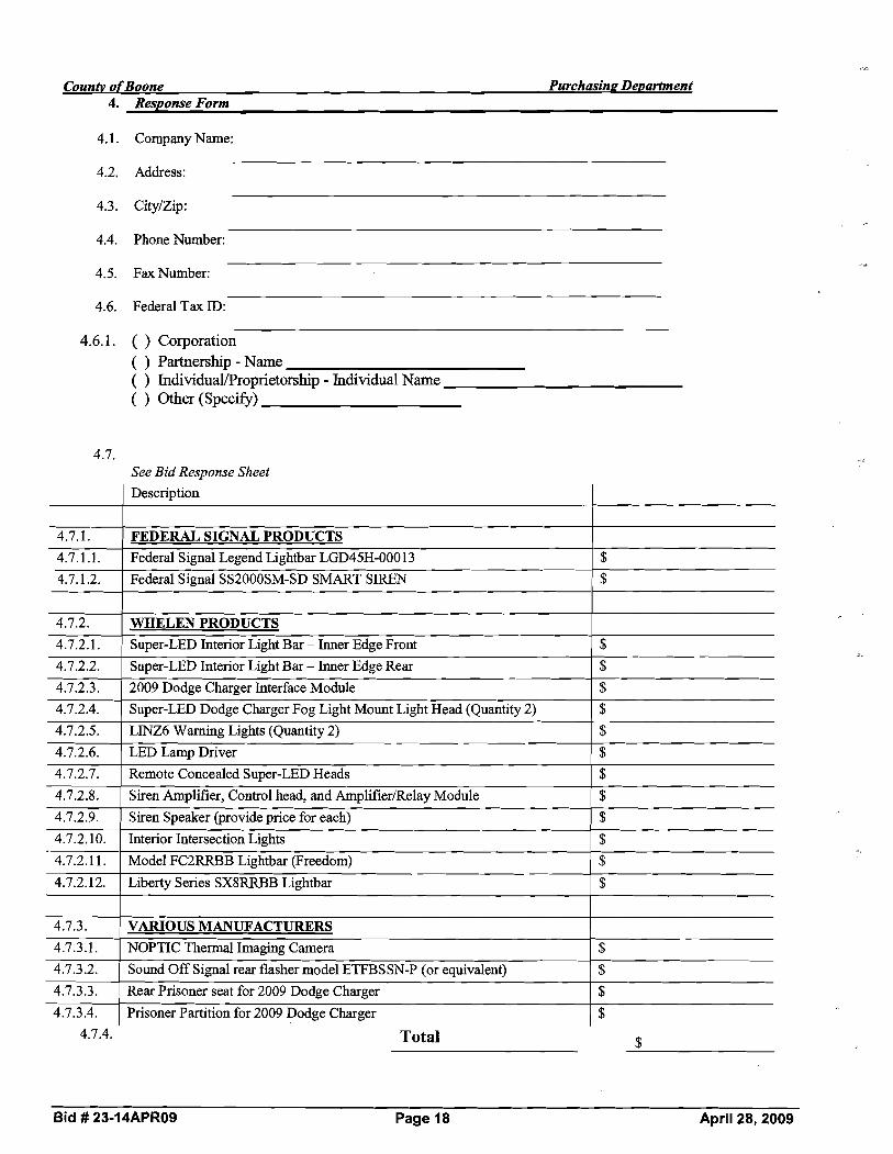
CounG ofBoone Purchasing De~artment 4. Response Form
4.1. Company Name:
4.2. Address:
4.4. Phone Number:
4.5. Fax Number:
4.6. Federal Tax ID: -
4.6.1. ( ) Corporation ( ) Partnership - Name ( ) Individual/Proprietorship- Individual Name ( ) Other (Specify)
4.7. See Bid Response Sheet Description
4.7.1. FEDERAL SIGNAL PRODUCTS 4.7.1.1. Federal Signal Legend Lightbar LGD45H-00013 $
4.7.1I2 1 SMART SIREN $Federal Signal ~ ~ 2 0 0 0 ~ ~ - S D 1
4.7.2.2. Super-LED Interior Light Bar - Inner Edge Rear $
4.7.2.3. 2009 Dodge Charger Interface Module $
4.7.2.4. Super-LED Dodge Charger Fog Light Mount Light Head (Quantity 2) $
4.7.2.5. LINZ6 Warning Lights (Quantity 2) $
4.7.2.6. LEDLampDriver $
4.7.2.7. Remote Concealed Super-LED Heads $
4.7.2.8. Siren Amplifier, Control head, and AmplifierRelay Module $
4.7.2.9. Siren Speaker (provide price for each) $
4.7.2.10. Interior Intersection Lights $
4.7.2.11. Model FC2RRBB Lightbar (Freedom) $
4.7.2.12. Liberty Series SX8RRBB Lightbar $
4.7.3. VARIOUS MANUFACTURERS 4.7.3.1. NOPTIC Thermal Imaging Camera $
4.7.3.2. Sound Off Signal rear flasher model ETFBSSN-P (or equivalent) $
4.7.3.3. Rear Prisoner seat for 2009 Dodge Charger $
4.7.3.4. Prisoner Partition for 2009 Dodge Charger $
4.7.4. Total $
Bid # 23-1 4APR09 Page 18 April 28,2009

4.8. Describe warranty, if applicable -Specify relation of section of RFB andlor attach additional pages as necessary)
4.9. Maximum percentage increase for all prices submitted for the three subsequent renewable contract periods:
1" Renewal % 2nd Renewal % 3*Renewal %
4.10. Will you honor the submitted prices for purchase by other entities in Boone County who Participate in cooperative purchasing with Boone County, Missouri? Yes No
4.1 1.
4.12.
Delivery After Receipt of Order:
The undersigned offers to furnish and deliver the articles or services as specified at the prices and terms stated and in strict accordance with all requirements contained in the Request for Bid which have been read and understood, and all of which are made part of this order.
4.12.1. Authorized Representative (Sign By Hand):
4.12.2. Type or Print Signed Name:
4.12.3. Date:
Bid # 23-14APR09 Page 19 April 28, 2009
..s

AFFIDAVIT OF COMPLIANCE WITH OSHA TRAINING REQUIREMENTS PURSUANT TO 8292.675 RSMo
(FOR ALL PUBLIC WORKS PROJECTS AFTER 8/28/2009)
County of ) )ss
State of 1
My name is . I am an authorized agent of
(Company). I am aware of the requirements for OSHA training set out in 9292.675Revised Statutes of
Missouri for those working on public works. All requirements of said statute have been fully satisfied and there has been no
exception to the full and complete compliance with said provisions relating to the required OSHA training for all those who
performed services on this public works contract for Boone County, Missouri.
NAME OF PROJECT:
Affiant Date
Printed Name
Subscribed and sworn to before me this day of ,20-.
Notary Public
NOTE: Failure to return this Affidavit with project close-out documents may result in referral of this project to the Department of Labor and Industrial Relations for further action to determine compliance with RSMo Sec. 292.675.
Bid # 23-14APR09 Page 20 April 28, 2009

(Please complete and return with Contract)
Certification Regarding Debarment, Suspension, Ineligibility and Voluntary Exclusion
Lower Tier Covered Transactions
This certification is required by the regulations implementing Executive Order 12549, Debarment and Suspension, 29 CFR Part 98 Section 98.5 10, Participants' responsibilities. The regulations were published as Part W of the May 26, 1988, Federal Register (pages 19160-192 11). -.
(BEFORE COMPLETING CERTIFICATION, READ INSTRUCTIONS FOR CERTIFICATION)
(1) The prospective recipient of Federal assistance funds certifies, by submission of this proposal, that neither it nor its principals are presently debarred, suspended, proposed for debarment, declared ineligible, or voluntarily excluded from participation in this transaction by any Federal department or agency.
(2) Where the prospective recipient of Federal assistance finds is unable to certify to any of the statements in this certification, such prospective participant shall attach an explanation to this proposal.
SM D~MM , SANS R?& Name and Title of ~Gthorized Representative
05-&--~9 Date
Bid # 23-14APR09 Page 21 April 28, 2009

CERTIFICATION OF INDMDUAL BIDDER
.,LPursuant to Section 208.009 RSMo, any person applying for or receiving any grant, contract, loan, retirement, welfare, health benefit, post secondary education, scholarship, disability benefit, housing benefit or food assistance who is over 18 must verifjl. their lawful presence in the United States. Please indicate compliance below. Note: A parent or guardian applying for a public benefit on behalf of a child who is citizen or permanent resident need not comply.
1. I have provided a copy of documents showing citizenship or lawful presence in the United States. (Such proof may be a Missouri driver's license, U.S. passport, birth certificate, or immigration documents). Note: If the applicant is an alien, verification of lawful presence must occur prior to receiving a public benefit.
2. I do not have the above documents, but provide an affidavit (copy attached) which may allow for temporary 90 day qualification.
3. I have provided a completed application for a birth certificate pendingin the State of . Qualification shall terminate upon receipt of the birth certificate or determination that a birth certificate does not exist because I am not a United States citizen.
Applicant Date Printed Name
Bid # 23-14APR09 Page 22 April 28, 2009
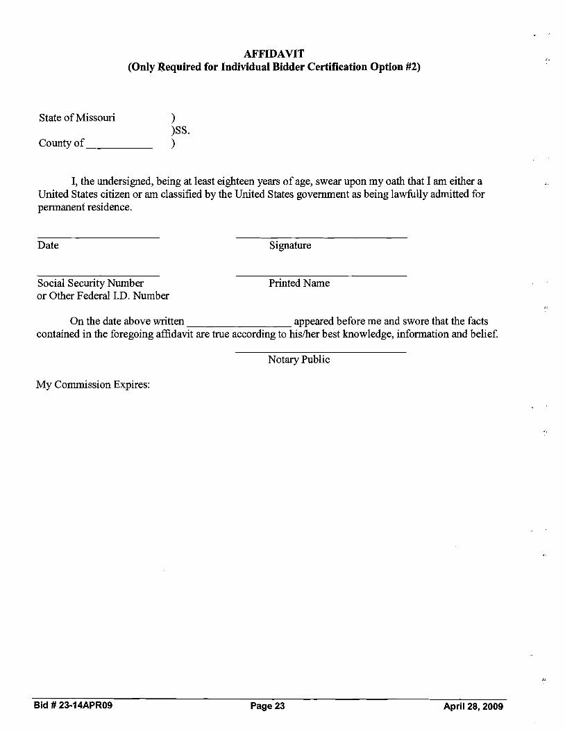
AFFIDAVIT (Only Required for Individual Bidder Certification Option #2)
State of Missouri ) )SS.
County of 1
I, the undersigned, being at least eighteen years of age, swear upon my oath that I am either a United States citizen or am classified by the United States government as being lawfully admitted for permanent residence.
Date Signature
Social Security Number Printed Name or Other Federal I.D. Number
On the date above written appeared before me and swore that the facts contained in the foregoing affidavit are true according to hisher best knowledge, information and belief.
Notary Public
My Commission Expires:
Bid # 23-14APR09 Page 23 April 28, 2009

Standard Terms and Conditions
Boone County Purchasing 60 1 E. Walnut, Room 209
Columbia, MO 65201
Tyson Boldan, Buyer Phone: (573) 886-4392- Fax (573) 886-4390
2.
1. Responses shall include all charges for packing, delivery, installation, etc., (unless otherwise specified) to the Boone County Department identified in the Request for Quotation andlor Proposal.
2. The Boone County Commission has the right to accept or reject any part or parts of all bids, to waive technicalities, and to accept the offer the County Commission considers the most advantageous to the County. Boone County reserves the right to award this bid on an item-by-item basis, or an "all or none" basis, whichever is in the best interest of the County.
Bidders must use the bid forms provided for the purpose of submitting bids, must retmi the quotation and bid sheets comprised in this bid, give the unit price, extended totals, and sign the bid.
When products or materials of any particular producer or manufacturer are mentioned in our specifications, such products or materials are intended to be descriptive of type or quality and not restricted to those mentioned.
Do not include Federal Excise Tax or Sales and Use Taxes in bid process, as law exempts the County fiom them.
The delivery date shall be stated in definite terms, as it will be taken into consideration in awarding the bid.
The County Commission reserves the right to cancel all or any part of orders if delivery is not made or work is not started as guaranteed. In case of delay, the Contractor must notify the Purchasing Department.
In case of default by the Contractor, the County of Boone will procure the articles or services fiom other sources and hold the Bidder responsible for any excess cost occasioned thereby.
Failure to deliver as guaranteed shall disqualify Bidder fiom future bidding.
Prices must be as stated in units of quantity specified, and must be firm. may not be considered unless specified in the bid specifications.
Bids qualified by escalator clauses
No bid transmitted by fax machine will be accepted.
The County of Boone, Missouri expressly denies responsibility for, or ownership of any item purchased until same is delivered to the County and is accepted by the County.
The County reserves the right to award to one or multiple respondents. The County also reserves the right to not award any item or group of items if the services can be obtained fiom a state or other governmental entities contract under more favorable terms.
Bid # 23-14APR09 Page 24 April 28, 2009

Boone County Purchasing 601 E. Walnut, Room 209
Columbia,MO 65201 "NoBidnResponse Form
Tyson Boldan, Buyer (573) 886-4392- Fax: (573) 886-4390
"NO BID RESPONSE FORM"
NOTE: COMPLETE AND RETURN THIS FORM ONLY IF YOU DO NOT WANT TO SUBMIT A BID
If you do not wish to respond to this bid request, but would like to remain on the Boone County vendor list for this service/commoditv,please remove form and return to the Purchasing Department by mail or fax.
If you would like to FAX ths 'To Bid" Response Form to our office, the FAX number is (573) 886-4390.
Bid: 23-14APR09 - Sheriff's Department Emergency Equipment
Business Name:
Address:
Telephone:
Contact:
Date:
Bid # 23-1 4APR09 Page 25 April 28,2009

CERTIFIED COPY OF ORDER
STATE OF MISSOURI } May Session of the April Adjourned Term. 20 09 ea.
County of Boone
In the County Commission of said county, on the I 9th day of M ~ Y 20 09
the following, among other proceedings, were had, vlz:
Now on this day the County Commission of the County of Boone does hereby award bid 25-16MAR09-Old Highway 63 North Asphalt Overlay Project to APAC Missouri. It is further ordered the Presiding Commissioner is hereby authorized to sign said contract.
Done this 1 9th day of May, 2009.
~Cnne thM. Pearson Presiding Commissioner
ATTEST:
Karen I df. -Miller
Wendy S. No en District I Commissioner Clerk of the County Commission n
Skip ~ lk in \ District I1 Commissioner
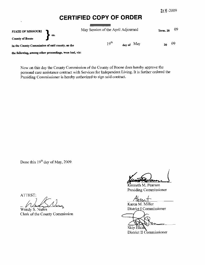
CERTIFIED COPY OF ORDER
)ea.
May Session of the April Adjourned Term. 20 09STATE OF MISSOURI
County of Boone
In the County Commission of said county, on the 19'h day of 20 09
the following, among other proceeding, were had, viz:
Now on this day the County Commission of the County of Boone does hereby approve the personal care assistance contract with Services for Independent Living. It is further ordered the Presiding Commissioner is hereby authorized to sign said contract.
Done this 19thday of May, 2009.
- tKenneth M. Pearson Presiding Commissioner
ATTEST:
Karen M. Miller Wendy S. No en District I Commissioners L nClerk bf the County Commission
District 11 C\ornmissioner

AGREEMENT FOR PURCHASE OF IN HOME SERVICES
THIS AGREEMENT, dated the Lday of L , 20 (19, is entered into between Boone County, Missouri, through its County Commission, hereinafter referred to as the "County" and Services for Independent Living, hereinafter referred to as the "Provider".
WHEREAS, the County is desirous of providing Person Care Assistance (CDS) services as stated in the application received by the Office of Corr~mur~ity Services which is hereby incorporated by reference as fully as if herein set forth.
NOW THEREFORE, the County and Provider agree:
1. Provider shall provide Personal Care Assistance (CDS) services in accordance with the application of Provider that is on file in the Office of Community Services. Services purchased under this Agreement shall be provided to Boone County residents residing outside the City of Columbia and be provided to persons who meet the eligibility requirements established by the County.
2. Services specified in this Agreement shall be purchased from the contracting in home service agency of the client's choice, using the fixed rate amount designated herein. No specific dollar allocation shall be made to any agency.
3. Provider agrees and understands that refusal to deliver services to any client authorized by the County may constitute a breach of this Agreement unless prior approval has been obtained from the County.
4. Provider shall conform at all times to applicable State Licensing Rules for Home Health agencies and/or Missouri Department of Health and Senior Services Standards for Homemaker/Personal Care, Respite Care, and Personal Care Assistance (CDS) Services.
5. Provider shall keep and maintain authorization documents, record of payments received from the County, and complete records to verify the delivery of services in accordance with the terms of this Agreement for a period of three (3) calendar years following expiration of this Agreement.
6. All such records and documents pertinent to this Agreement shall be subject at all times to inspection, review, or audit by County personnel and other personnel duly authorized by the County, subject to prior authorization by the patient.
7. If Provider is terminated from service with the County or goes out of business, all applicable records or copies thereof shall be furnished to the County at the time of termination or cessation of business.
8. County shall be permitted to conduct an on-site review of the program operated by the Provider, at a time mutually agreed upon by both parties.
9. Provider agrees that if a suit or claim is filed or made against County, or its officers or employees, based upon the Provider's performance under this agreement, or the County's selection of Provider as a contracting agency, or the County's failure to supervise or monitor Provider's performance under this agreement, Provider will indemnify, defend and hold harmless the County against said suit or claim and pay whatever damages may be assessed against the County. Provider is entitled to use whatever defenses it has in law or fact against such claimants and County agrees to assist in the factual defenses raised by the Provider.

Provider shall not assign the responsibility of this Agreement to another party without prior written approval of the County.
Payment shall be made only for those services specified in this Agreement as authorized by the County. Said authorization shall be furnished to the Provider in writiqg by the ColumbiaIBoone County Health Department and shall include the name of the Provider, the period of authorization, the type of service, the level of service, and the client to be served.
The rate of reimbursement for the period January 1, 2009 through December 31, 2009 is $4.24 per unit of service for homemakerlpersonal care services, $3.78 per unit of service for respite care services, and $3.69 for personal care assistance (CDS). A unit of service is one-quarter hour. Reimbursement rates may be increased at the sole discretion of the County so as to ensure that reimbursement rates correspond with current state rates for these services. In all circumstances, County's obligation to make payments hereunder are subject to annual appropriations made available by County to fund its obligations to Provider and further conditioned upon there being a sufficient unencumbered balance remaining in said appropriation.
The County shall pay the provider on the basis of monthly invoices, which shall be submitted to the Office of Community Services within fifteen days following the last day of each billing period on forms provided by .the County for this purpose. Any invoices submitted after the fifteen day time period will be held over until the next month's billing cycle.
Supplemental invoices will be accepted for payment within 60 days of service delivery. Any supplemental invoices submitted later than 60 days after service delivery will not be reimbursed.
The Provider must submit the final invoice for reimbursement to the County no more than fifteen (15) days after the contract ends or is terminated.
This Agreement shall begin January 1, 2009 or the date on which the Agreement has been signed by both parties, whichever is later, and shall end on December 31, 2009.
Provider agrees that the County may at its sole option and with agreement of the Provider renew this Agreement for three (3) consecutive one-year terms. Additionally, Provider agrees and understands that the County may require supplemental information to be submitted by Provider prior to any renewal of this Agreement.
This Agreement may be terminated by either party upon thirty (30) days notice, with or without cause; notice shall be delivered by certified mail, return receipt requested, or in person with proof of delivery.
It is further understood and agreed that either party at any time may, with cause related to adequacy of performance, terminate this contract immediately by written notice.
If this Agreement is terminated for any reason, the obligation of the County shall be limited to payment for services provided in accordance with the Agreement prior to the date of termination.
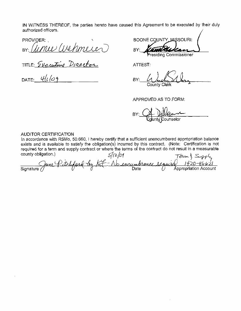
IN WITNESS THEREOF, the parties hereto have caused this Agreement to be executed by their duly authorized officers.
<
residing Commissioner
TITLE: sy,o,& V/U&& ATTEST:
DATE: d l b? BY:
APPROVED AS TO FORM:
BY: k&ntj&ounselor
AUDITOR CER1-IFICATION In accordance with RSMo, 50.660, 1 hereby certify that a sufficient unencumbered appropriation balance exists and is available to satisfy the obligation(s) incurred by this contract. (Note: Certification is not required for a term and supply contract or where the terms of the contract do not result in a measurable county obligation.) q'/2/0f

227 -2009
CERTIFIED COPY OF ORDER
STATE OF MISSOURI May Session of the April Adjourned Term. 20 09) ea. County of Boone
In the County Commission of said county, on the 19th day of May 20 09
the following, among other proceedings, were had, viz:
Now on this day the County Commission of the County of Boone does hereby approve the Agreement for Engineering Services with Allstate Consultants LLC for the Sapp Building Relocation. It is further ordered the Presiding Commissioner is hereby authorized to sign said agreement.
Done this 1 9 ' ~ day of May, 2009.
enneth M. Pearson d Presiding Commissioner
Karen M. Miller District I Commissioner
Clerk of the County Commission
District I1 cbmmissioner

AGREEMENT FOR ENGINEERING SERVICES
CLIENT: BOONE COUNTY, MISSOURI 801 E. WALNUT STREET, ROOM 245 COLUMBIA, MO 65201
BILLING: SAME AS CLIENT
DATE: May 8,2009 PROJECT #: 08052.01
PROJECT NAME AND LOCATION:
SAPP BUILDING RELOCATION TO BOONE COUNTY FAIRGROUNDS CONSTRUCTION TESTING AND STRUCTURAL SPECIAL SERVICES INSPECTION BOONE COUNTY, MO
SCOPE OF SERVICES 1FEE FOR SERVICES: Allstate Consultants LLC, 33 12 LeMone Industrial Blvd., Columbia, MO agree to provide engineering services related to CONSTRUCTION TESTING AND STRUCTURAL SPECIAL SERVICES INSPECTONS for the above named project at the above listed location. These services will be provided for on an hourly basis as defined herein and as defined in the standard terms and conditions in Addendum A of this agreement, for an estimated cost of $3000.00.
Allstate Consultants LLC will complete all of the work on an hourly bases.
BILLING: An invoice will be sent at the first of each month reflecting the services performed. Payment is due in 30 days and delinquent in 45 days.
CONTRACT: Acceptance of this agreement will serve as Allstate Consultant's notice to proceed and together with the standard terms and conditions and Scope and Schedule of Work Addendum attached hereto represent the formal contractual agreement.
Proposed By: Accepted By: /
Donald W. Fischer AUstate Consultants LLC 3312 LeMone Industrial Blvd. Columbia, MO 65201 573-875-8799 (phone) Print Name / Title 573-875-8850 (fax) [email protected]

SCOPE AND SCHEDULE OF WORK ADDENDUM
This Addendum describes the scope and schedule of work to be performed by Allstate Consultants in connection with the SAPP BUILDING RELOCATION CONSTRUCTION TESTING AND STRUCTURAL INSPECTIONS located on an existing outdoor Horse Arena located on the west side of Fairground Drive between the existing Expo Center on the north and an asphalt access road and existing Livestock Building # 1 to # 4 on the south at the Boone County Fairgrounds, in Section 29, Township 49 North, Range 12 West, Boone County, Missouri and this Addendum is incorporated by reference into the attached Contract for Engineering and Surveying Services.
The anticipated schedule of work will include the following:
1. Observe the exposed subgrade prior to the fill being placed as recommended by the geotechnical report. 2. Perform density and moisture test on the compacted fill (soil or granular) as recommended by the
geotechnical report. 3. Observe and probe all footings using a cone penetrometer to verify bearing capacity as recommended by
the structural steel plans prior to the steel being place or concrete poured. 4. Observe and verify the size and placement of reinforcing steel as recommended by the structural plans
prior to concrete being poured. 5. Sample the concrete as recommended by the structural steel plans. 6. Perform other special inspections as recommended by the structural steel plans. 7. Should revisions be made to the plans that involve additional work other that above described, then
additional compensation will be billed based on the hourly rates and reimbursables as defined in Addendum A of this proposal. However, no additional work would be performed without your direction or permission.
8. Allstate Consultants could begin this project upon your notice to proceed.
Proposed By: Accepted By: /
Donald W! Fischer Allstate Consultants LLC
Print Name / Title

ADDENDUM A -STANDARD TERMS AND CONDITIONS
Allstate Consultants LLC (the Firm) shall perform the professional services outlined in this agreement for the stated fee agreement. The Firm will perform the services in a timely manner with due and reasonable diligence consistent with sound professional practices. The Firm will perform services under this Agreement in a manner consistent with that degree of care and skill ordinarily exercised by members of the same profession currently practicing under similar circumstances.
Access to Site: Unless otherwise stated, the Firm will have access to the site for activities necessary for the performance of the services. 'The Firm will take precautions to minimize damages due to these activities but have not included in the fee the cost of restoration of any resulting damage.
Fee: A Fixed fee, if stated, shall constitute the total compensation due. A Percentage fee, if stated, shall be calculated on the basis of the total cost of the work designed and specified by the firm. An Estimated fee, if stated, will be calculated on an hourly basis, and the estimate shall not be exceeded by more than twenty percent without written approval of the Client. A Not-To-Exceed fee, if stated, will be calculated on an hourly basis, and will not be exceeded without prior written approval of the Client. An Hourly fee, iisiated, will be based on the actual hours expended on the project and will be calculated on an hourly basis.
Hourly Rate: Where the fee is to be calculated on an hourly basis, the rates shall be as follows:
PRINCIPAL....................... $ 1 1 .OO ................................................................................................... ENGINEER Ill...........................................................................................................................$104.00 ENGINEER II ...................... $94.00........................................................................................................ ENGINEER I .................................................................................................................................$83.00 TECHNICIAN VllSURVEYOR Ill .....................................................................................................$94.00 TECHNICIAN VISURVEYOR II...............................................................................................$83.00 TECHNICIAN IVISURVEYOR I........................ ........................................................................$69.00 TECHNICIAN Ill........................... $59.00............................................................................................ TECHNICIAN II................................................................................................................................$43.00 TECHNICIAN I ..................... $30.00........................................................................................................ CREW (2 MEN) ........................ $111.00................................................................................................. CREW (3 MEN) ........................ .. $121.00........................................................................................... INVESTIGATOR II .................... $94.00............................................................................................... SENIOR INVESI'IGATOR ...............................................................................................................$65.00 INVESTIGATOR I........................... .....................................................................................$51.00 EXPERT TESTIMONY II....................... ..................................................................................$250.00 EXPERT TESTIMONY I.......................... .........$175.00 GPS RECEIVERS (PER UNIT) .................. ..................................................................$06.001day TRAFFIC COUNTERS (PER UNIT) ..................... $3O.OOlday............................................................. MILEAGE.....................................................................................................................................IRS Rate ATV (PER UNIT) ..................................................................................................................$lO6.OO/day EXPENSES (Lodging. Meals, Printing, Research, 8etc.) ......................................................Actual Cost
Annual Rate Increase: Rates will be adjusted annually. Adjusted rates will be incorporated and billed into applicable agreements and contracts.
Reimbursable Expenses: The Client shall reimburse the Firm to direct expenses incurred during performance of the service, including printing charges, taxes, mileage, public transportation cost, tolls, permit fees, equipment rentals, long distance communication, and other miscellaneous expenses.
Billing/Payments: Statements for the Firm's services shall be submitted at the completion of the project. Statements shall be due upon receipt and payable within 30 days after their date. Payments shall not be contingent upon any other payments to the Client by others. If not paid within 30 days, the Firm may, without waiving any claim or right against the Client, and without liability whatsoever to the Client, terminate the performance of all services. Payments to the Firm shall not be withheld, postponed or made contingent on the construction, completion or success of the project. No withholdings, deductions or offsets shall be made from the Firm's compensation for any reason.
Indemnification: The Client shall indemnify and hold harmless the Firm and all of its personnel from and against any and all claims, damages, losses and expenses (including reasonable attorney's fees) arising out of or resulting from the performance of the services, provided that any such claim, damage, loss, or expense is caused in whole or in part by the negligent act, omission andlor strict liability of the Client, anyone directly or indirectly employed by the Client (except the firm), or anyone for whose acts they may be liable.
Project Responsibilities: Neither the professional activities of the Firm nor the presence of the employees at a construction site, shall relieve any Contractor or any other entity of their obligations, duties and responsibilities including, but not limited to, construction means, methods, sequence, techniques or procedures necessary for performing, superintending or coordinating all portions of the Work of construction in

accordance with the contract documents and any health or safety precautions required by any regulatory agencies. The Client agrees his Contractor is solely responsible for jobsite safety, and warrants that this intent shall be made evident in the Client's agreement with the Contractor.
Termination of Services: The Agreement may be terminated by the Client or the Firm after seven days written notice should the other fail to perform its obligation hereunder. In the event of termination, the Client shall pay the Firm for all services rendered to the date of termination, all reimbursable expenses, and termination expenses.
Ownership of Documents: All documents produced by the Firm under this agreement shall remain the property of the Firm and may not be used by the Client for any other endeavor without the written consent of the Firm. The "original" plat shall be returned to the firm after recording in the Boone County records.
Applicable Laws: Unless otherwise specified, this agreement shall be governed by the laws of the State of Missouri.

CERTIFIED COPY OF ORDER
STATE OF MISSOURI May Session of the April Adjourned Term. 20 09) e . County of Boone
In the County Commission of said county, on the 1 9th day of 20 09
the following, among other proceedings,were had, viz:
Now on this day the County Commission of the County of Boone does hereby authorize a closed meeting on Wednesday, May 27,2009, at 1 :30 p.m. The meeting will be held in Room 243 of the Roger B. Wilson Boone County Government Center at 80 1 E. Walnut, Columbia, Missouri, as authorized by 610.021 (1) RSMo. to discuss legal actions, causes of action or litigation involving a public governmental body and any confidential or privileged communications between a public governmental body or its representatives and its attorneys.
Done this 1 9th day of May, 2009.
/&nneth M. Pearson Presiding Commissioner
ATTEST:
Karen M. Miller Wendy S. N en DistripI-Cqmmissioner Clerk of the County Commission
Li 2&~1,.. ~erc-=k
DistrictSkip I1 Co'hm issioner