cfa-rs232 serial converter board data sheet 2014-02-07 · pdf filecrystalfontz america, inc....
TRANSCRIPT

Crystalfontz America, Incorporated
Crystalfontz America, Incorporated12412 East Saltese Avenue
Spokane Valley, WA 99216-0357
Phone: 888-206-9720Fax: 509-892-1203Email: [email protected]: www.crystalfontz.com
Data Sheet Release Date 2014-02-07 for the CFA-RS232 Serial Converter Board
Hardware Revision: v1.0
SPECIFICATIONS

Crystalfontz America, Inc. Data Sheet Release Date 2014-02-07www.crystalfontz.com CFA-RS232 Serial Converter Board (Hardware v1.0)
Page 2
Revision Information - - - - - - - - - - - - - - - - - - - - - - - - - - - - - - - - - - - - - - - - - - - - - - - - - - - - - - - - - - - - 3
Notices - - - - - - - - - - - - - - - - - - - - - - - - - - - - - - - - - - - - - - - - - - - - - - - - - - - - - - - - - - - - - - - - - - - - - 3
Difference Between “Full Swing” RS232 And “Logic Level, Inverted” Serial - - - - - - - - - - - - - - - - - - - - - 5
CFA-RS232 Shipped Installed On Compatible Intelligent LCD Modules - - - - - - - - - - - - - - - - - - - - - - - - 5
Buy CFA-RS232 Separately For Other Uses - - - - - - - - - - - - - - - - - - - - - - - - - - - - - - - - - - - - - - - - - - - 5
Illustrations - - - - - - - - - - - - - - - - - - - - - - - - - - - - - - - - - - - - - - - - - - - - - - - - - - - - - - - - - - - - - - - - - - - 6
Absolute Maximum Ratings - - - - - - - - - - - - - - - - - - - - - - - - - - - - - - - - - - - - - - - - - - - - - - - - - - - - - - - 8
DC Characteristics - - - - - - - - - - - - - - - - - - - - - - - - - - - - - - - - - - - - - - - - - - - - - - - - - - - - - - - - - - - - - 8
Input Supply Voltages - - - - - - - - - - - - - - - - - - - - - - - - - - - - - - - - - - - - - - - - - - - - - - - - - - - - - - - - - - - 8
ESD (Electro-Static Discharge) - - - - - - - - - - - - - - - - - - - - - - - - - - - - - - - - - - - - - - - - - - - - - - - - - - - - 9
Connection Information - - - - - - - - - - - - - - - - - - - - - - - - - - - - - - - - - - - - - - - - - - - - - - - - - - - - - - - - - - 9
Connector Locations - - - - - - - - - - - - - - - - - - - - - - - - - - - - - - - - - - - - - - - - - - - - - - - - - - - - - - - - - 9
J1 Connector Pin Assignments (Default and Alternate) - - - - - - - - - - - - - - - - - - - - - - - - - - - - - - - - 10
J2 Connector Pin Assignments (Includes GPIO Connections) - - - - - - - - - - - - - - - - - - - - - - - - - - - 12
Jumper And Pins For Power - - - - - - - - - - - - - - - - - - - - - - - - - - - - - - - - - - - - - - - - - - - - - - - - - - 13
Logic Level GPIO +5 Volt Tolerant Pins - - - - - - - - - - - - - - - - - - - - - - - - - - - - - - - - - - - - - - - - - - 13
Typical GPIO Current Limits - - - - - - - - - - - - - - - - - - - - - - - - - - - - - - - - - - - - - - - - - - - - - - - - - - - 14
USB Interface With Power Through CFA-RS232 - - - - - - - - - - - - - - - - - - - - - - - - - - - - - - - - - - - - 14
Recommended Cables - - - - - - - - - - - - - - - - - - - - - - - - - - - - - - - - - - - - - - - - - - - - - - - - - - - - - - - - - 15
Cables For RS-232 Communications Through J1 Connector To Host - - - - - - - - - - - - - - - - - - - - - 15
Cable For Power Through J2 Connector - - - - - - - - - - - - - - - - - - - - - - - - - - - - - - - - - - - - - - - - - - 15
Make Your Own Cable To Connect To J1 - - - - - - - - - - - - - - - - - - - - - - - - - - - - - - - - - - - - - - - - - 15
Care And Handling Precautions - - - - - - - - - - - - - - - - - - - - - - - - - - - - - - - - - - - - - - - - - - - - - - - - - - - 16
Quality Assurance Standards - - - - - - - - - - - - - - - - - - - - - - - - - - - - - - - - - - - - - - - - - - - - - - - - - - - - - 17
CONTENTS
Crystalfontz America, Inc. Data Sheet Release Date 2014-02-07www.crystalfontz.com CFA-RS232 Serial Converter Board (Hardware v1.0)
Page 3
REVISION INFORMATION
NOTICES
Data Sheet Revision History
Data Sheet Release Date: 2014-02-07Clarified specifications in DC Characteristics (Pg. 8) and made minor changes in wording.
Data Sheet Release Date: 2013-12-19New Data Sheet for CFA-RS232 Serial Converter Board, hardware v1.0.
The CFA-RS232 has not changed since 2005. Until now, information about the CFA-RS232 was included in compatible Intelligent LCD Module Data Sheets. Because we’ve added to our line of compatible Intelligent LCD Modules, we decided that it made sense to publish information about the CFA-RS232 in its own Data Sheet.
CFA-RS232 Hardware Revisions
For information about hardware revisions, see Part Change Notifications (PCNs) and Product Update Notices (PUNs) under the Notices tab on the website page for the CFA-RS232.
To ensure that the appropriate people in your organization receive notices, please ask them to subscribe at www.crystalfontz.com/news/pcn.php.
About Volatility
The CFA-RS232 has nonvolatile memory.

Crystalfontz America, Inc. Data Sheet Release Date 2014-02-07www.crystalfontz.com CFA-RS232 Serial Converter Board (Hardware v1.0)
Page 4
Figure 1. Photo Of CFA-RS232 Mounted On A Compatible Intelligent LCD Module (CFA735)
The bidirectional CFA-RS232 Serial Converter Board is a small printed circuit assembly that can be mounted on a compatible LCD Intelligent Module. It has a 16-pin female connector “J3” that mates with the male 16-pin connector “H1” on the back of compatible modules.
Less than one inch high and a little over one inch wide, the CFA-RS232 is an easy way to add “full swing” RS232 serial interface for compatible modules. This add-on peripheral converts compatible modules that have “logic level, inverted” serial interface to “full swing” RS232 serial interface.
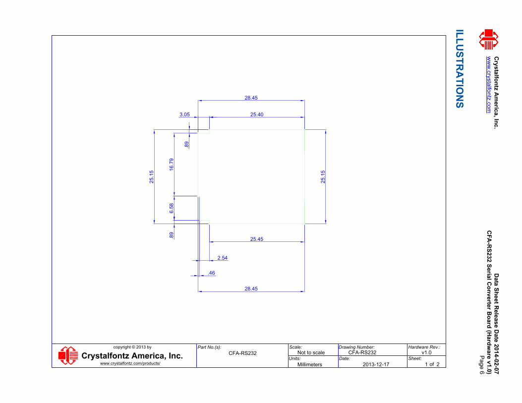
Overall dimensions are 28.45 (W) mm x 25.15 (H) mm (1.10” (W) x 0.99”)
Weight is 6 grams.
The CFA-RS232 has an Sipex SP3220EEY-L driver/receiver pair.
Additional Fine Print
Certain applications using Crystalfontz America, Inc. products may involve potential risks of death, personal injury, or severe property or environmental damage (“Critical Applications”). CRYSTALFONTZ AMERICA, INC. PRODUCTS ARE NOT DESIGNED, INTENDED, AUTHORIZED, OR WARRANTED TO BE SUITABLE FOR USE IN LIFE-SUPPORT APPLICATIONS, DEVICES OR SYSTEMS OR OTHER CRITICAL APPLICATIONS. Inclusion of Crystalfontz America, Inc. products in such applications is understood to be fully at the risk of the customer. In order to minimize risks associated with customer applications, adequate design and operating safeguards should be provided by the customer to minimize inherent or procedural hazard. Please contact us if you have any questions concerning potential risk applications.
Crystalfontz America, Inc. assumes no liability for applications assistance, customer product design, software performance, or infringements of patents or services described herein. Nor does Crystalfontz America, Inc. warrant or represent that any license, either express or implied, is granted under any patent right, copyright, or other intellectual property right of Crystalfontz America, Inc. covering or relating to any combination, machine, or process in which our products or services might be or are used.
All specifications in Data Sheets and on our website are, to the best of our knowledge, accurate but not guaranteed. Corrections to specifications are made as any inaccuracies are discovered.
Company and product names mentioned in this publication are trademarks or registered trademarks of their respective owners.
Copyright © 2013 by Crystalfontz America, Inc., 12412 East Saltese Avenue, Spokane Valley, WA 99216-0357 U.S.A

Crystalfontz America, Inc. Data Sheet Release Date 2014-02-07www.crystalfontz.com CFA-RS232 Serial Converter Board (Hardware v1.0)
Page 5
DIFFERENCE BETWEEN “FULL SWING” RS232 AND “LOGIC LEVEL, INVERTED” SERIALBoth of the two serial interfaces used in our compatible LCD Intelligent Modules have firmware that bring the two UART pins (Tx & Rx) of the module’s microcontroller to its “H1” connector. The CFA-RS232 converts the 0v to +5v (logic level, inverted) Rx and Tx signals from the module’s microcontroller to RS232 levels.
“Full Swing” RS232 Serial
Bidirectional 9600 / 19200 / 115200 baud ESD protected RS232 serial interface is provided by the CFA-RS232 mounted on a compatible module. This interface is the correct choice if your embedded controller or host system has a RS232 serial port (-5v to +5v “full swing” serial interface, typically through a UART).
“Logic Level, Inverted” Serial
Module’s with this interface expose the UART Tx & Rx (“logic level, inverted”, 0v to +3.3v Tx nominal, 0v to +5.0v Rx nominal) signals on pin 1 and pin 2 of the module's connector “H1”. If your embedded processor is close to the module, you can cable its UART Rx and Tx pins directly to the module’s Tx and Rx pins. No RS232 level translators are required on either end.
CFA-RS232 SHIPPED INSTALLED ON COMPATIBLE INTELLIGENT LCD MODULESThe CFA-RS232 is preinstalled when you order a CFA635-xxx-KS or CFA735-xxx-KT Intelligent LCD Module. When you order a CFA835 Intelligent LCD Module on our website, you can order a CFA-RS232 in the “Customize and Add to Cart” feature.
BUY CFA-RS232 SEPARATELY FOR OTHER USESThe CFA-RS232 can also be used with other 3.0 to 5.0 volt devices. Sold as a separate item, the CFA-RS232 can interface between your host (any microcontroller) and your device with a compatible connectors.
Fully assembled, the CFA-RS232 comes ready to connect with all three headers preinstalled. The connectors are widely available.
Note: Be sure to align pins correctly before pushing the board into the socket.
Cry
stalfo
ntz A
meric
a, Inc
.D
ata
Sh
eet Releas
e Date 201
4-02-07
ww
w.crystalfontz.com
CF
A-R
S232
Seria
l Co
nve
rter Bo
ard (H
ard
ware v1.0)
Page 6
ILL
US
TR
AT
ION
S
25.403.05
28.45
.89
16.7
96.
58.8
9
25.1
5
.46
2.54
25.45
28.45
25.1
5
www.crystalfontz.com/products/Crystalfontz America, Inc.
Scale:
Units:
copyright © 2013 by Drawing Number:
Date:
Hardware Rev.:
Sheet:
Part No.(s):
of
CFA-RS232
2013-12-17
Not to scale
Millimeters
CFA-RS232 v1.0
1 2

Cry
stalfo
ntz A
meric
a, Inc
.D
ata
Sh
eet Releas
e Date 201
4-02-07
ww
w.crystalfontz.com
CF
A-R
S232
Seria
l Co
nve
rter Bo
ard (H
ard
ware v1.0)
Page 7
Illustration Only
www.crystalfontz.com/products/Crystalfontz America, Inc.
Scale:
Units:
copyright © 2013 by Drawing Number:
Date:
Hardware Rev.:
Sheet:
Part No.(s):
of
CFA-RS232
2013-12-17
Not to scale
N/A
CFA-RS232 v1.0
2 2
Crystalfontz America, Inc. Data Sheet Release Date 2014-02-07www.crystalfontz.com CFA-RS232 Serial Converter Board (Hardware v1.0)
Page 8
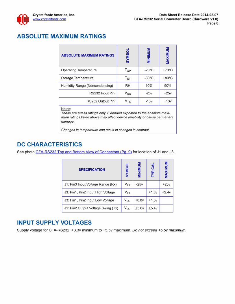
ABSOLUTE MAXIMUM RATINGS
DC CHARACTERISTICSSee photo CFA-RS232 Top and Bottom View of Connectors (Pg. 9) for location of J1 and J3.
INPUT SUPPLY VOLTAGESSupply voltage for CFA-RS232: +3.3v minimum to +5.5v maximum. Do not exceed +5.5v maximum.
ABSOLUTE MAXIMUM RATINGS
SY
MB
OL
MIN
IMU
M
MA
XIM
UM
Operating Temperature TOP -20°C +70°C
Storage Temperature TST -30°C +80°C
Humidity Range (Noncondensing) RH 10% 90%
RS232 Input Pin VRX -25v +25v
RS232 Output Pin VTX -13v +13v
Notes:These are stress ratings only. Extended exposure to the absolute maxi-mum ratings listed above may affect device reliability or cause permanent damage.
Changes in temperature can result in changes in contrast.
SPECIFICATION
SY
MB
OL
MIN
IMU
M
TY
PIC
AL
MA
XIM
UM
J1: Pin3 Input Voltage Range (Rx) VIH -25v +25v
J3: Pin1, Pin2 Input High Voltage VIH +1.8v +2.4v
J3: Pin1, Pin2 Input Low Voltage VOL +0.8v +1.5v
J1: Pin2 Output Voltage Swing (Tx) VOL +5.0v +5.4v

Crystalfontz America, Inc. Data Sheet Release Date 2014-02-07www.crystalfontz.com CFA-RS232 Serial Converter Board (Hardware v1.0)
Page 9
ESD (ELECTRO-STATIC DISCHARGE)Tx and Rx pins: +15 kV Human Body Model +15 kV IEC1000-4-2 Air Discharge +8 kV IEC1000-4-2 Contact Discharge
The remainder of the circuitry is industry standard CMOS logic and is susceptible to ESD damage. Please use industry standard antistatic precautions as you would for any other static sensitive devices such as expansion cards, motherboards, or integrated circuits. Ground your body, work surfaces, and equipment.
CONNECTION INFORMATION
Connector Locations
The top side of the CFA-RS232 has the Crystalfontz logo silk-screened onto it and has male two connectors. The bottom side of the CFA-RS232 does not have the Crystalfontz logo and has one female connector.
The “J1” and “J2” connectors are on the top side of the mounted CFA-RS232, facing away from the module. The “J3” connector is on the bottom of the mounted CFA-RS232, facing towards the module.
Figure 2. CFA-RS232 Top and Bottom View of Connectors
J3J1J2
Top Bottom

Crystalfontz America, Inc. Data Sheet Release Date 2014-02-07www.crystalfontz.com CFA-RS232 Serial Converter Board (Hardware v1.0)
Page 10
Figure 3. CFA-RS232 Side View of Connectors
1. “J1” is the male 10-pin (0.1” center) RS232 host communications connector on the top side.
2. “J2” is the male 16-pin 2 mm “pass through” connector on the to side, passing through to the “J3” female16-pin 2 mm connector on the bottom side of the board.
3. “J3” is the female 16-pin 2 mm connector on the bottom side that mates with “H1” male 16-pin 2 mm connector on the compatible module.
J1 Connector Pin Assignments (Default and Alternate)
The pin order of your motherboard's header will determine if the compatible LCD Intelligent Module's pin assignments (“full swing” RS232 serial) need to be “Default” or “Alternate”, as described below.
Note
The WR-232-Y22 cable, when connected to the “J1” of the CFA-RS232 Serial Converter, provides two connectors on its opposite end. The connector a few inches from the end has a “Default” pin assignment and the connector at the very end has an “Alternate” pin assignment. By using the WR-232-Y22 cable, you can avoid changing jumpers on the CFA-RS232 Serial Converter.
“J1” connector for “full swing” RS232 to host
“J2” connector has five GPIOs available when mated with compatible LCD Intelligent Modules.
“J3” connector to compatible module’s“H1” connector
Bottom of CFA-RS232 Top of CFA-RS232

Crystalfontz America, Inc. Data Sheet Release Date 2014-02-07www.crystalfontz.com CFA-RS232 Serial Converter Board (Hardware v1.0)
Page 11
J1 Default Pin Assignments
The jumpers JP2, JP4, and JP6 are closed by default at the factory, selecting the “J1” connector “Default RS232 Pin Assignments”. This default pin assignment allows a low cost ribbon cable such as the WR-232-Y08 to connect the compatible LCD Intelligent Module via “full swing” RS232 serial to a PC's DB9 COM port.
J1 Alternate Pin Assignments
Note: As you can see in the above photo, the alternate pin sequence is different from the pin sequence of the default pin assignments.
DEFAULT STATE ALTERNATE STATE
JP1 open JP1 closed
JP2 closed JP2 open
JP3 open JP3 closed
JP4 closed JP4 open
JP5 open JP5 closed
JP6 closed JP6 open
J1 J1J1 J1LCD Tx/Host Rx
LCD Rx/Host Tx
Ground
1 2
3 4
5 6
7 8
9 10
closed
closed
closed
open
open
open
J1 Alternate Pin Assignments
X Ignore “10”
LCD Tx/Host Rx
LCD Rx/Host Tx
Ground
1 10
2 9
3 8
4 7
5 6
closed
closed
closed
open
open
open
J1 Default Pin Assignments

Crystalfontz America, Inc. Data Sheet Release Date 2014-02-07www.crystalfontz.com CFA-RS232 Serial Converter Board (Hardware v1.0)
Page 12
By opening jumpers JP2, JP4, and JP6 and closing JP1, JP3, and JP5, you can select the “Alternate RS232 Pin Assignments”.
If there is a matching 0.1-inch center, 10-pin RS232 connector on your system's motherboard, then in most cases a simple straight-through ribbon cable such as WR-232-Y22 cable can be used to connect from the compatible module (“full swing” RS232 serial) to a motherboard's 10-pin header.
J2 Connector Pin Assignments (Includes GPIO Connections)
The “H1” connector on compatible LCD Intelligent Modules has 5 pins that can be used for General Purpose Input or Output (GPIO). The CFA-RS232 mounted on the “H1” passes through the signals to the “J2” connector.
Figure 4. CFA-RS232 “J2” Connector Pin Assignments
Reserved. Make no connection.
Reserved. Make no connection.
Reserved. Make no connection.
GPIO3 (ATX Host Reset Control)
GPIO1 (ATX Host Power Sense)
Reserved. Make no connection.
+5v
Reserved. Make no connection.
Reserved. Make no connection. Reserved. Make no connection.
Reserved. Make no connection.
Reserved. Make no connection.
GPIO2 (ATX Host Power Control)
GPIO0
GPIO4
Ground
J2
16
2 1
15

Crystalfontz America, Inc. Data Sheet Release Date 2014-02-07www.crystalfontz.com CFA-RS232 Serial Converter Board (Hardware v1.0)
Page 13
Jumper And Pins For Power
Logic Level GPIO +5 Volt Tolerant Pins
DCCHARACTERISTICS
SY
MB
OL
MIN
IMU
M
MA
XIM
UM
CO
NT
RO
LL
ER
AN
D
BO
AR
D
Input High Voltage VIH
0.42*(VDD-2 v)+1v
If VDD = +3.3v
= +1.55v
+5.5v
Input Low Voltage VIL -0.3v
0.32*(VDD-2v)+0.75v
If VDD = +3.3v
= +1.17v
Output High Voltage VOH +2.4v +3.3v
Output Low Voltage VOL +0.4v +1.3v
J2 J1
16
Jumper JP13 is closed by default at the factory. It allows power to be supplied to J1.J1 Default Pin Assignments – Pin 4
J1 Alternate Pin Assignments – Pin 7J2 Pin Assignments – Pin 16
Crystalfontz America, Inc. Data Sheet Release Date 2014-02-07www.crystalfontz.com CFA-RS232 Serial Converter Board (Hardware v1.0)
Page 14
Typical GPIO Current Limits
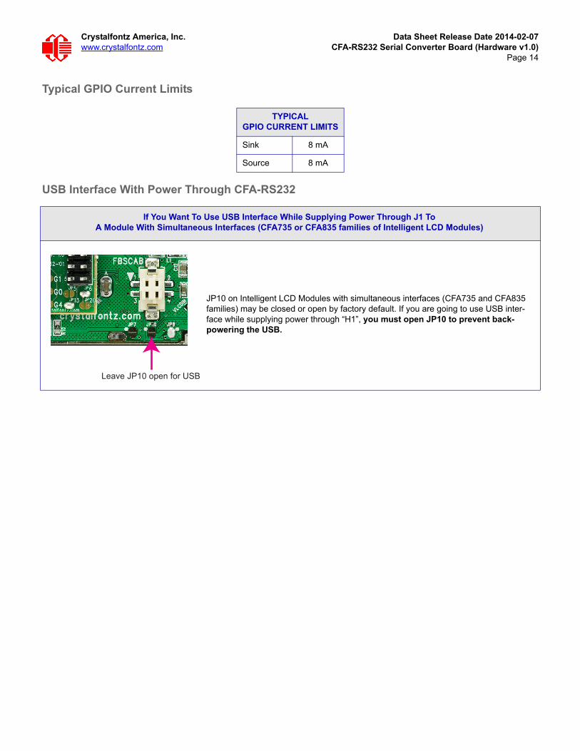
USB Interface With Power Through CFA-RS232
TYPICALGPIO CURRENT LIMITS
Sink 8 mA
Source 8 mA
If You Want To Use USB Interface While Supplying Power Through J1 ToA Module With Simultaneous Interfaces (CFA735 or CFA835 families of Intelligent LCD Modules)
JP10 on Intelligent LCD Modules with simultaneous interfaces (CFA735 and CFA835 families) may be closed or open by factory default. If you are going to use USB inter-face while supplying power through “H1”, you must open JP10 to prevent back-powering the USB.
Leave JP10 open for USB

Crystalfontz America, Inc. Data Sheet Release Date 2014-02-07www.crystalfontz.com CFA-RS232 Serial Converter Board (Hardware v1.0)
Page 15
RECOMMENDED CABLES
Cables For RS-232 Communications Through J1 Connector To Host
WR-232-Y08
The WR-232-Y08 cable is about 2 feet 2.55 inches long. Connect the cable’s 0.1" 2x5 female connector to the CFA-RS232’s “J1” 10-pin connector. Connect the cable’s RS232 DB9 9-pin female connector to your host’s external 9-pin serial port.
WR-232-Y22
The WR-232-Y22 cable is about 2 feet 1 inches long. Connect the cable’s 0.1" 2x5 female connector to the CFA-RS232’s “J1” 10-pin connector. Connect the cable’s second 0.1" 2x5 female connector to your host’s motherboard 10-pin connector. Choose standard or alternate pin assignments.
WR-232-Y23
The WR-232-Y23 cable is about 2 feet 1.75 inches long. Connect the cable’s 0.1" 2x5 female connector to the CFA-RS232’s “J1” 10-pin connector. Connect the cable’s RS232 DB9 9-pin female connector to your host’s external 9-pin serial port. Choose standard or alternate pin assignments.
Cable For Power Through J2 Connector
WR-PWR-Y24
The WR-PWR-Y24 cable is about 2 feet 2.55 inches long. Use this cable to supply power (no communications) to a compatible Intelligent LCD Module through the mounted CFA-RS232 serial converter from the host’s power supply. Connect the cable’s 16-pin female connector to the CFA-RS232’s 16-pin male “J2” connector. Connect the cable’s 4-pin male connector directly to your host’s power supply connector.
Caution: When using this cable with Intelligent LCD Modules with simultaneous interfaces (CFA735 and CFA835 families), be sure to open JP10 on the module. This will avoid back-powering the USB subsystem. See USB Interface With Power Through CFA-RS232 (Pg. 14).
Make Your Own Cable To Connect To J1
The following parts may be used to make your own cable to connect to the CFA-RS232’s “J2” connector:
16-position housing: Hirose DF11-16DS-2C / Digi-Key H2025-ND.
Crimping contact (tape & reel): Hirose DF11-2428SCF / Digi-Key H1504TR-ND.
Crimping contact (loose): Hirose DF11-2428SC / Digi-Key H1504-ND.
Pre-terminated interconnect wire: Hirose / Digi-Key H3BBT-10112-B4-ND is typical.

Crystalfontz America, Inc. Data Sheet Release Date 2014-02-07www.crystalfontz.com CFA-RS232 Serial Converter Board (Hardware v1.0)
Page 16
CARE AND HANDLING PRECAUTIONSFor optimum operation of the CFA-RS232 and to prolong its life, please follow the precautions described below.
ESD (Electro-Static Discharge) Specifications
The circuitry is industry standard CMOS logic and is susceptible to ESD damage. Please use industry standard antistatic precautions as you would for any other static sensitive devices such as expansion cards, motherboards, or integrated circuits. Ground your body, work surfaces, and equipment.
Design And Mounting
Do not disassemble or modify.
Do not reverse polarity to the power supply connections. Reversing polarity will immediately ruin the CFA-RS232 and may ruin any device connected to it.
Avoid Shock, Impact, Torque, Or Tension
Do not expose the CFA-RS232 to strong mechanical shock, impact, torque, or tension.
Do not drop, toss, bend, or twist the module.
Do not place weight or pressure on the module.
Caution
All electronics may contain harmful substances. Avoid contamination by using care to avoid damage during handling. If any residues, gases, powders, liquids, or broken fragments come in contact with your skin, eyes, mouth, or lungs, immediately contact your local poison control or emergency medical center.
Operation
Your circuit should be designed to protect the CFA-RS232 from ESD and power supply transients.
Observe the operating temperature limitations: a minimum of -20°C to a maximum of 70°C noncondensing with minimal fluctuation. Operation outside of these limits may shorten life and/or harm display.
Operate away from dust, moisture, and direct sunlight.
Storage And Recycling
Store in an ESD-approved container away from dust, moisture, and direct sunlight with humidity less than 90% noncondensing.
Observe the storage temperature limitations: a minimum of -30°C minimum to +80°C non-condensing maximum with minimal fluctuations. Rapid temperature changes can cause moisture to form, resulting in permanent damage.
Do not allow weight to be placed on the modules while they are in storage.
Please recycle your outdated Crystalfontz modules at an approved facility.
Crystalfontz America, Inc. Data Sheet Release Date 2014-02-07www.crystalfontz.com CFA-RS232 Serial Converter Board (Hardware v1.0)
Page 17
QUALITY ASSURANCE STANDARDS
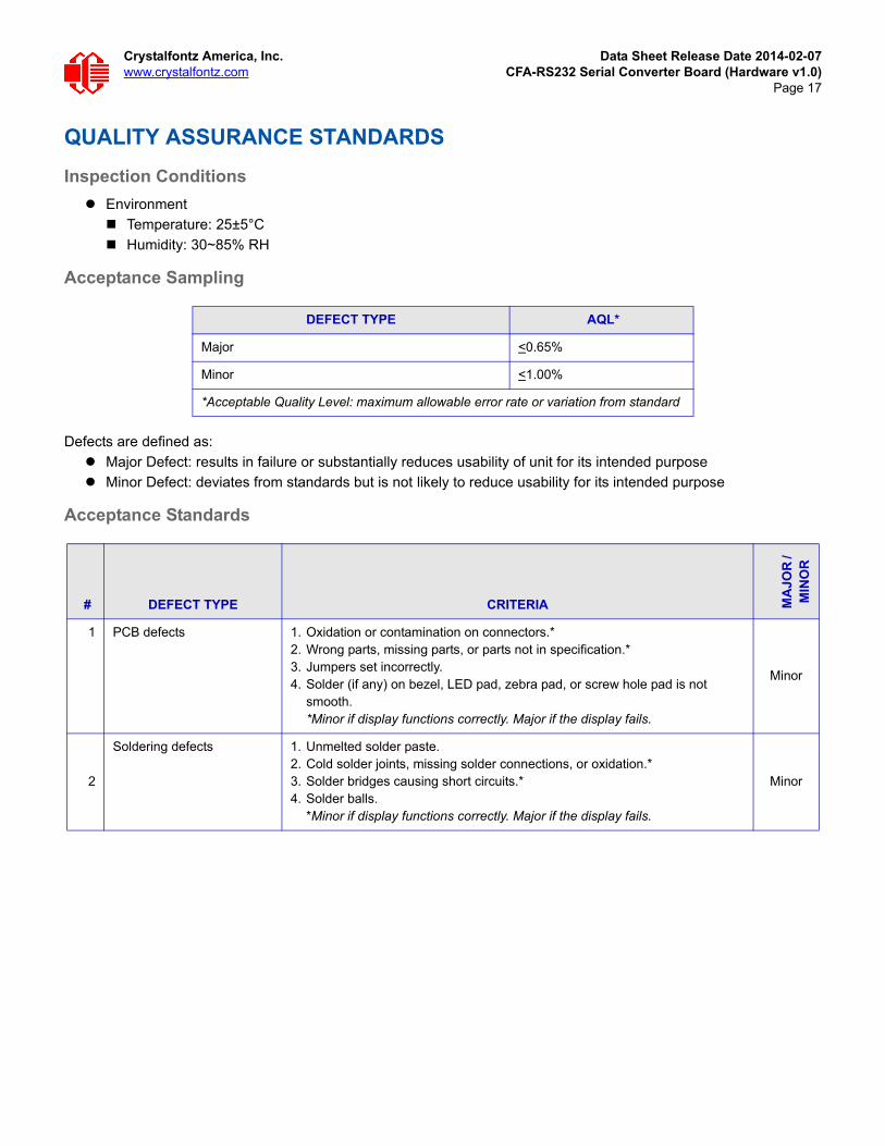
Inspection Conditions
Environment
Temperature: 25±5°C
Humidity: 30~85% RH
Acceptance Sampling
Defects are defined as:
Major Defect: results in failure or substantially reduces usability of unit for its intended purpose
Minor Defect: deviates from standards but is not likely to reduce usability for its intended purpose
Acceptance Standards
DEFECT TYPE AQL*
Major <0.65%
Minor <1.00%
*Acceptable Quality Level: maximum allowable error rate or variation from standard
# DEFECT TYPE CRITERIA MA
JOR
/ M
INO
R
1 PCB defects 1. Oxidation or contamination on connectors.*2. Wrong parts, missing parts, or parts not in specification.*3. Jumpers set incorrectly.4. Solder (if any) on bezel, LED pad, zebra pad, or screw hole pad is not
smooth.*Minor if display functions correctly. Major if the display fails.
Minor
2
Soldering defects 1. Unmelted solder paste.2. Cold solder joints, missing solder connections, or oxidation.*3. Solder bridges causing short circuits.*4. Solder balls.
*Minor if display functions correctly. Major if the display fails.
Minor