cfd analysis of heat transfer in a helical coil - ethesis
TRANSCRIPT

CFD ANALYSIS OF HEAT TRANSFER IN A HELICAL COIL
HEAT EXCHANGER USING FLUENT
APRIL 7, 2013 NATIONAL INSTITUTE OF TECHNOLOGY, ROURKELA

1 | P a g e
1 PROJECT REPORT 2013
CFD ANALYSIS OF HEAT TRANSFER IN A HELICAL COIL HEAT EXCHANGER USING FLUENT
A thesis submitted in partial fulfillment of the requirements for the degree of
Bachelor of technology
In Mechanical engineering
By SHASHI SHEKHAR
Under the guidance of
Dr. A. K. Satapathy
Department of Mechanical Engineering
National Institute of Technology
Rourkela 769008

2 | P a g e
2 PROJECT REPORT 2013
CERTIFICATE
National Institute of Technology
Rourkela
This is to certify that the work in this thesis entitled, “CFD ANALYSIS OF HEAT
TRANSFER IN A HELICAL COIL HEAT EXCHANGER USING FLUENT”
submitted by Shashi Shekhar in partial fulfillment of the requirements for the
degree of Bachelor of Technology in Mechanical Engineering, during session 2012-
2013 is an authentic work carried out by him under my supervision and guidance.
To the best of my knowledge, the matter embodied in the project has not been submitted to any other University / Institute for the award of any Degree or Diploma.
Dr. Ashok Kumar Satapathy
(Supervisor)
Associate Professor
Dept. of Mechanical Engineering
National Institute of Technology Rourkela

3 | P a g e
3 PROJECT REPORT 2013
ACKNOWLEDGEMENT
I would like to express my deep sense of gratitude and respect to our supervisor
Prof. ASHOK KUMAR SATAPATHY, for his excellent guidance, suggestions and
constructive criticism. He has not only been a wonderful supervisor but also a
genuine person. I consider myself extremely lucky to be able to work under the
guidance of such a dynamic personality.
Last, but not the least I extend my sincere thanks to all M.Tech students
(Mechanical Engineering for making my project a successful one, for their
valuable advice in every stage and also giving me absolute working environment. I
would like to thank all whose direct and indirect support helped me completing
my thesis in time.
Shashi shekhar
109me0421
Bachelor of technology, mechanical engineering

4 | P a g e
4 PROJECT REPORT 2013
CONTENT:
Certificate 2
Acknowledgement 3
Abstract 5
1. Introduction about the project 6
2. Literature survey 9
3. CFD analysis 12
3.1 . Boundary condition 13
3.2 . Dimensions 14
4. Results and Discussions 15
3.3 . Contours 16
3.4 . Plots 20
5 Conclusions 22
6 References 23
7 Nomenclature 24

5 | P a g e
5 PROJECT REPORT 2013
ABSTRACT
This thesis focuses on the CFD analysis of flow of fluid through a helical coil heat
exchanger. Also on the enhancement in convective heat transfer in between the fluid
and the surrounding surface in these helical coils which has been a major topic of
study as reported by many researchers. As helical coil have compact size and higher
heat transfer coefficient they are widely used in industrial applications such as power
generation, nuclear industry, process plant, refrigeration, food industry, etc.
In this study, an attempt has been made to study the parallel flow and counter
flow of inner hot fluid flow and outer cold fluid flow, which are separated by copper
surface in a helical coil heat exchanger. The temperature contours, velocity vectors,
total pressure contours, total heat dissipation rate from the wall of the tube were
calculated and plotted using ANSYS 13.0. Copper was used as the base metal for
the inner and outer pipe and the fluid was taken as hot water for inner flow and cold
water for outer flow.

6 | P a g e
6 PROJECT REPORT 2013
CHAPTER 1
INTRODUCTION ABOUT THE PROJECT

7 | P a g e
7 PROJECT REPORT 2013
Heat transfer in helical coils are higher than as compared to straight coils.
Because of its compact size, higher film coefficient, they are widely used in
industrial applications like power generation, nuclear industry, process plant, heat
recovery system, chemical process industries etc. These heat exchanger are used to
control the temperature of the reactors for exothermic reactions. They have less
expensive design. Helical geometry allows the effective handling at higher
temperatures and extreme temperature differentials without any highly induced
stress or expansion of joints. Helical coil heat exchanger consists of series of stacked
helical coiled tubes and the tube ends are connected by manifolds, which also acts
as fluid entry and exit locations.
Schematic diagram of helical coil heat exchanger
Natural convection is a process or type of heat transfer, in which the fluid
motion is caused by density differences in the fluid occurring due to temperature
gradients. Here the fluid which surrounds a heat source receives heat, becomes less
8 | P a g e
8 PROJECT REPORT 2013
dense and rises. The fluid that is surrounding the hot fluid is cooler and then moves
in to replace it. Then further that cooler fluid gets heated and the process continues,
forming convection current. The driving force for this process is buoyancy, a result
of difference in the fluid density. Natural convection has attracted a great deal of
attention from researchers because of its presence both in nature and engineering
applications.
Forced convection in a heat exchanger is the transfer of heat from one moving
stream to another stream through the wall of the pipe. The cooler fluid removes heat
from the hotter fluid as it flows along or across it. If it moves along the hot stream
then it’s called parallel flow and if they are across then its counter flow.
Heat transfer coefficient:
As we studied, if the heat transfer is occurring in a stream due to density difference
then its convective heat transfer. If a film is placed in between fluid of different
density then conduction heat transfer will occur through that film. The equation of
rate of heat transfer under steady state is given by:
Q=hA (tw-tatm),
Where h= coefficient of heat transfer (W/m2K)
A= area of the wall
Tw=wall temperature
Tatm=surrounding temperature.
The value of ‘h,Heat Transfer Coefficient’ depends upon the properties of fluid.. It
depends on the different properties of fluid, dimensions of the film surface and
velocity of the fluid flow as well as nature of flow.

9 | P a g e
9 PROJECT REPORT 2013
CHAPTER 2
LITERATURE SURVEY

10 | P a g e
10 PROJECT REPORT 2013
J.S. Jayakumar [1]. According to his study it was attempted to run experimental
and theoretical analysis of a helical coiled heat exchanger, in which heat transfer is
between fluid-fluid. There exists no previous analysis for helical coil heat
exchanger though there are many researches for double pipe heat exchanger.
Experimental setup was fabricated to get the output in estimation of heat transfer
characteristics, then this experimental data was compared with the CFD calculation
using CFD package FLUENT 6.2.
Experimental setup and procedure:-
The pipe for the construction of helical coil has 10 mm inner diameter and
12.7 mm outer diameter. Pitch of the coil is 300 mm and tube pitch is 30 mm.
Material used was stainless steel SS304.
The setup consist of a shell which encloses the helical coil. Cold fluid enters
from bottom to top leaving the shell through the nozzle at top. The coil assembly can
be replaced if needed.
A tank was provided with electrical heaters to heat the water that to be
circulated in helical coil. It consist of three heaters having total power of 5000W. To
control the temperature of water at the inlet a controller was connected. A centrifugal
pump with ½ HP power rating is connected to pump the hot water in helical coil.
RTD (resistance thermometer detectors) are added to measure the inlet and outlet
temperatures of the hot fluid and the values are available at the display screen.
Cooling water from a constant temperature tank is provided through the shell side
and its inlet and outlet temperatures are measured. Its flow is adjusted such that the
rise in temperature is not exceeding 5oC.
After the temperature attain a constant steady value, by conducting 5 different
flow rates through the coil and for three different values of inlet temperature of the
helical coil, measurements are taken of the values of flow rates of the hot and cold
fluids, temperature at inlet and exit is noted and the power input to the heater and
the pump are noted.
These heat transfer characteristics helical coil setup is further studied using
CFD code FLUENT. The CFD results matched accordingly with the experimental
results within the error limit. A relation was developed to calculate the inner heat
transfer coefficient of the helical coil. Based on the results generated under different
conditions it may be used to obtain a generalized correlation that may be applicable
to other various coil configuration.

11 | P a g e
11 PROJECT REPORT 2013
A.B. Korane [2] has performed comparative analysis to study friction factor
characteristics of shell and helically coiled tube heat exchanger. He continued his
studies on two geometries helical coil heat exchanger and square coil pattern having
round cross section. Both the coil were constructed by using a 3.33 meter straight
copper tube having 10 mm inner diameter and 12 mm outer diameter in 6 turns with
pitch 0 mm. the heat exchanger was made by copper tubing and brass connection.
Both laminar and turbulent flow were analyzed for the Reynolds number range of
886-6200 and having different mass flow rates. The hot water tank with the 3KW
capacity thermostatic electric heater was used to pump the hot water through the
tubing. The mass flow rates varies from 0.003-0.024 kg/s for the hot water which
comes from hot water tank. Cold water with the flow rate of 0.003-0.024kg/s is
supplied. And the flow rates are controlled by the ball valves provided.
The two helical coils tube side friction factor was determined individually for
laminar and turbulent flow. The performance was then discussed according to
friction factor and pressure drop.
According to this study he came to the conclusion that
Performance for the square coil is more than circular helical coil.
Empirical correlations were developed for both square and circular
coils on both laminar and turbulent flow.
Both the heat exchangers were analyzed for laminar and turbulent flow
configuration.
The friction factor is minimum for the square coil as compared to circular coil.
Daniel Flórez-Orrego [3] have studied the characteristics of single phase cone
shaped helical coil heat exchanger. They conducted experiments on a prototype of
cone helical coil heat exchanger with maximum diameter of 15 cm and minimum
diameter as 7.5 cm, 3/8 inch pitch and axial length of 40 cm. the flow was in both
laminar and turbulent and the range of Reynolds number and prandtl number are
4300-18600 and 2-6 respectively. According to this study nusselt number can be
found out by Nu=CRemPrn, where C,m are constants that to be determined and nis
the prandtl number index which is taken as 0.4. An empirical correlation was
proposed for average nusselt number, and it was found that there is a maximum
deviation of 23%. Inclination of the velocity vector components in the secondary
flow was observed unlike in the straight helical coils. These correlations are not
reliable and it failed to give any deviation in nusselt number due to the tapering and
the effect of pitch.

12 | P a g e
12 PROJECT REPORT 2013
CHAPTER 3
CFD ANALYSIS

13 | P a g e
13 PROJECT REPORT 2013
3.1. BOUNDARY CONDITIONS:
We are taking the inlet and outlet conditions as velocity inlet and
pressure outlet. As this is counter flow of inner hot fluid flow and outer cold fluid
flow so there will be two inlet and outlet respectively. There is a pipe which
separates the two flows which is made by copper. The detail about all boundary
conditions are as follows. Inner fluid is taken as hot water and outer fluid is taken
as cold water.
Boundary
condition
type
Velocity
magnitude
Turbulent
kinetic
Energy
Turbulent
dissipation
rate
temperature
Inner inlet Velocity Inlet
1.6 m/s 0.01 0.1 333 K
Inner outlet Pressure
Outlet
- - - -
Outer inlet Velocity Inlet
1.5m/s 0.01 0.1 283 K
Outer outlet Pressure
Outlet
- - - -

14 | P a g e
14 PROJECT REPORT 2013
3.2. DIMENSIONS:
Diameter of inner inlet= 0.6 inch
Diameter of inner pipe= 0.68 inch
Diameter of outer inlet= 0.84 inch
Diameter of outer pipe= 0.93 inch
Diameter of coil= 6 inch
Density is taken in y direction = 9.81 m/s2

15 | P a g e
15 PROJECT REPORT 2013
CHAPTER 4
RESULTS AND DISCUSSION
16 | P a g e
16 PROJECT REPORT 2013
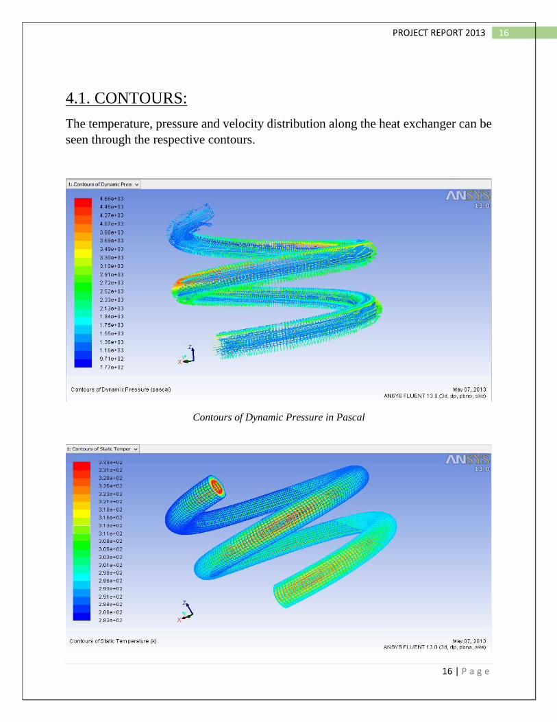
4.1. CONTOURS:
The temperature, pressure and velocity distribution along the heat exchanger can be
seen through the respective contours.
Contours of Dynamic Pressure in Pascal

17 | P a g e
17 PROJECT REPORT 2013
Contours of static temperature
Contours of total pressure
Contours of static temperature

18 | P a g e
18 PROJECT REPORT 2013
Contours of velocity vectors
Contours of turbulent dissipation rate

19 | P a g e
19 PROJECT REPORT 2013
Contours of turbulent kinetic energy
Contours of effective thermal conductivity

20 | P a g e
20 PROJECT REPORT 2013
4.2. PLOTS:
Scaled residuals
Wall Shear Stress Plot for Inner-wall And Outer-wall

21 | P a g e
21 PROJECT REPORT 2013
Total Pressure Plot for Innerwall and Outerwall
Surface Nusselt Number Plot for Inner-wall

22 | P a g e
22 PROJECT REPORT 2013
CONCLUSION:
ANSYS 13.0 is used for the numerical study of characteristics of heat transfer in a
helical coiled double pipe heat exchanger for parallel flow and these results were
compared with the experimental results from different study papers and were found
well within proper error limit. The study relates the heat transfer performance of the
parallel flow configuration and the counter flow configuration. Nusselt number was
determined for different points along the pipe length. It was found to be varying from
340-360.
We concluded different heat transfer properties at different points along the
pipe length in this study like temperature, static pressure, total pressure, kinetic
energy etc., for the constant temperature and constant wall heat flux conditions. The
velocity vector plot concludes that the fluid particles are undergoing an oscillatory
motion inside both the pipes. And pressure and temperature contours shows that
velocity and pressure values were higher for outer sides than inner sides of the pipes.

23 | P a g e
23 PROJECT REPORT 2013
REFERENCES
1. Experimental and CFD study of a single phase cone-shaped helical coiled
heat exchanger: an empirical correlation. By Daniel Flórez-Orrego, ECOS
June 26-29, 2012.
2. Helically Coiled Heat Exchangers by J.S.Jayakumar.
3. Experimental and CFD estimation of heat transfer in helically coiled heat
exchangers by J.S. Jayakumar, S.M. Mahajani, J.C. Mandal, P.K. Vijayan,
and Rohidas Bhoi, 2008, Chemical Engg Research and Design 221-232.
4. Heat Transfer Analysis of Helical Coil Heat Exchanger with Circular and
Square Coiled Pattern by Ashok B. Korane, P.S. Purandare, K.V. Mali,
IJESR, June 2012, vol-2, issue-6.
5. Noble, M.A., Kamlani, J.S., and McKetta, J.J., Heat Transfer in Spiral Coils,
Petroleum Engineer, April 1952, p. 723.
6. Minton P.E., Designing Spiral Tube Heat Exchangers, Chemical
Engineering, May 1970, p. 145.
7. Numerical analysis of forced convection heat transfer through helical
channels Dr. K. E. Reby Roy, IJEST, July-2012 vol-4.
8. Structural and Thermal Analysis of Heat Exchanger with Tubes of Elliptical
Shape by Nawras H. Mostafa Qusay R. Al-Hagag, IASJ, 2012,Vol-8 Issue-3

24 | P a g e
24 PROJECT REPORT 2013
NOMENCLATURE
1. A = area of heat transfer (m2)
2. De= Dean Number
3. H = heat transfer coefficient (Wm−2 K−1)
4. H = tube pitch (m)
5. K = thermal conductivity (Wm−1 K−1)
6. L= length of the pipe (m)
7. Nu= Nusselt number
8. Pr = Prandtl number
9. Q = heat transferred (W)
10. R= inner radius of the tube (m)
11. R = resistance the flow of thermal energy (W−1m2 K)
12. Rc = pitch circle radius of the pipe (m)
13. Re= Reynolds number
14. U = velocity (m s−1)
15. U = overall heat transfer coefficient (Wm−2 K−1)
16. V= volume (m3)
17. Α = helix angle (rad)
18. δ = curvature ratio
19. Δ = (temperature) difference (K)
20. μ = viscosity (kgm−1 s−1)
21. ρ = density (kgm−3)
22. av = average
23. i = internal
24. LM = log mean
25. o = external
26. ov = overall
27. w = wall