cfd simulation for predicting the wind effect on the high rise building: net tower surabaya
TRANSCRIPT

Narotama International Conference on Civil Engineering 2015 (NICCE-2015)
CFD simulation for predicting the wind effect on the high rise building: NET Tower Surabaya
DANI HARMANTO (UNIVERSITY OF DERBY), M. IKHSAN SETIAWAN, SRI WIWOHO M. (UNIVERSITAS NAROTAMA)
ABSTRACT The use of CFD is becoming a norm in the predicting the fluid flow in engineering especially in the mechanical engineering. However, concern has raised over the urban design area on the predicting the quality air and wind on the rise building / skyscraper. There are number of development of rise building is being built on the developing country where concern on the wind effect over pedestrian sometime is neglected. The aim and objective of this paper is demonstrating the use of CFD over a high rise building in Indonesia and taking a case study on the new propose building at NET Tower Narotama University Surabaya, Indonesia. The CFD will be based on one direction of wind and one velocity. The CFD will be based on the finite method. The predicted result will be showed that the distribution of velocity and pressure field will be shown. The case study is intended to provide a support and guidance for the future studies on developing a propose rise building in Surabaya in particular and Indonesia in general Keywords: CFD, wind, velocity INTRODUCTION High rise building is currently being built faster in the developing country compare with the European countries. This development is aiming to accommodate the raise of the number population. In the university, they will be aimed to accommodate more space for increase number of students, staff and expanding space for the laboratories. High rise building will have an effect on altering the speed and wind direction for the surrounding area. This should be noted by architect and also the authority when the rise building is on the proposal stage. The effect of the wind can be very uncomfortable on the pedestrian level and occasionally can be very dangerous. Predicted the wind direction on the rise building is becoming easier and efficient by using the Computational Fluid Dynamics simulation comparing with the traditional method using the wind tunnel. The flexibility of the CFD is unchallenged when it comes to the design changes. The authority should have requested on the designer to produce the effect of the wind speed and direction as the result of new design. There should be a maximum wind speed allowance produce by the rise building as some major city in the Europe and USA demanded. The presence of the rise building can be benefited or disadvantaged the surrounding on the pedestrian level. The effect will be depending on the shape of the building, orientation, size, obstacles and so on. Emil and Robert (1996) had classified number of different flows on the rise building as seen on the figure 1.
Figure 1 Regions of high surface wind speeds around a tall building
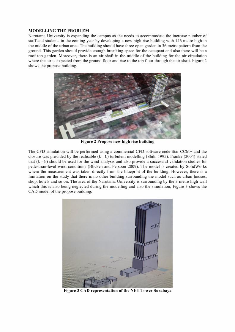
MODELLING THE PROBLEM Narotama University is expanding the campus as the needs to accommodate the increase number of staff and students in the coming year by developing a new high rise building with 146 metre high in the middle of the urban area. The building should have three open garden in 36 metre pattern from the ground. This garden should provide enough breathing space for the occupant and also there will be a roof top garden. Moreover, there is an air shaft in the middle of the building for the air circulation where the air is expected from the ground floor and rise to the top floor through the air shaft. Figure 2 shows the propose building.
Figure 2 Propose new high rise building
The CFD simulation will be performed using a commercial CFD software code Star CCM+ and the closure was provided by the realisable (k - Ԑ) turbulent modelling (Shih, 1995). Franke (2004) stated that (k - Ԑ) should be used for the wind analysis and also provide a successful validation studies for pedestrian-level wind conditions (Blicken and Persoon 2009). The model is created by SolidWorks where the measurement was taken directly from the blueprint of the building. However, there is a limitation on the study that there is no other building surrounding the model such as urban houses, shop, hotels and so on. The area of the Narotama University is surrounding by the 3 metre high wall which this is also being neglected during the modelling and also the simulation, Figure 3 shows the CAD model of the propose building.
Figure 3 CAD representation of the NET Tower Surabaya

For the CFD simulation, all the wall surfaces such as the ground or the building facades is being treated as a wall where the fluid cannot penetrated or through. Furthermore, the wall will be assumed as a smooth surface during the CFD simulation. The mesh was created into 2458157 cells and this being use to refine the small columns and edges. Figure 3 shows the detail mesh of the building.
Figure 4 Mesh Generation
The local meteorological data for Surabaya was taken using the windfinder.com (figure 5 shows the data of the average wind direction and velocity for Surabaya). It was suggested that the wind direction will be from the east and average wind velocity is 4m/s. The CFD will not use the high wind.
Figure 5 shows the wind direction for Surabaya

RESULTS Figure 6 shows the building will receive a maximum pressure over 24 pascal. This result should be compare and recalculate against the scale of the model. It can be said that the building will receive significant pressure and this is helped by the open garden where it allows the wind to go through.
Figure 6 the pressure field on the area of the building
The pressure shows on the figure 6 can be used to predict the turbulent area generated by the building. After the measurement, the turbulent will affect the area from 1 – 60 metre from the building. This area will receive a very high velocity in daily basis with velocity up to 2 – 5 m/s (see figure 8). This turbulent is being generated by the slot of the open garden and also the gap with the next building (see figure 9).

Figure 7 velocity field on the surrounding area
Figure 8 velocity magnitude field on the side view of the building

Figure 9 pressure field on the side view of the building
Figure 10 Pressure field on the top view of the building

Figure 11 Velocity magnitude field on the top view of the building
Figure 12 Velocity magnitude field on the top view of the building
As the building had been agreed and finalised, it will be very difficult and expensive to provide a change to the design. However, the prediction of the wind condition should be taken account when and during the design stage of the propose building. This will provide a better solution for the

surrounding area and also the NET Tower Surabaya. Furthermore, combination of architecture and wind environmental condition is never been easy and sometimes is very challenging. FUTURE RESEARCH Wind flow and turbulence within the urban canopy layer can influence the heating and ventilation of buildings, affecting the health and comfort of pedestrians, commuters and building occupants (Vardoulakis et.al, 2011). Architects have suggested that the architectural design, layout and decorations of the base of tall buildings should particularly respond to human scale. The design of the base should be tailored to basic human needs so that it provides protection from adversely reflected winds, rain, snow and hot sun. Whyte explained that various building ordinances and rules require developers to include plazas in their design. However, they were wind-blown and frequently vacant (Whyte, 1980). With regards to environmental factors such as ventilation, noise and thermal comfort, Lim (1994) finds that these are generally acceptable in Singapore’s high-rise public housing. As high-rise buildings tend to be tall and narrow, they should be designed such that when subjected to strong winds, the vibrations should not become unacceptable in terms of serviceability and safety (Balendra, 1993). CONCLUSION This paper has presented and described the use of the CFD simulation to help with the architecture, urban environment, and comfort of the surrounding area. The use of CFD on assessing the building design and optimisation based on the engineering point of view had been demonstrated through this case study. The following conclusion can be made that CFD will be very useful and can become a very power tool for helping to design a high rise building and this can help the designer, authority and developer. REFERENCES [1] Blocken, B. and Persoon, J. (2009). “Pedestrian wind comfort around a large football stadium in an urban environment: CFD
simulation, validation and application of the new dutch wind nuisance standard.” Journal of Wind Engineering and Industrial Aerodynamics, 97(5-6), 255–270.
[2] Blocken, B., Roels, S., and Carmeliet, J. (2004). “Modification of pedestrian wind comfort in the silvertop tower passages by an automatic control system.” Journal of Wind Engineering and Industrial Aerodynamics, 92(10), 849–873.
[3] Emil, S. and Robert, S. (1996). Wind Effects on Structures. John Wiley and Sons, Canada. [4] Franke, J., Hirsch, C., Jensen, A. G., Krus, H. W., Schatzmann, M., Westbury, P. S., Miles, S. D., Wisse, J. A., and Wright, N. G.
(2004). “Recommendations on the use of CFD in wind engineering.” Proceedings of the International Conference Urban Wind Engineering and Building Aerodynamics, J. P. A. J. vanBeeck, ed., von Karman Institute, Belgium.
[5] Mohammadipour, A. H. and Alavi, S. H. (2009). “The optimization of the geometric cross-section dimensions of raised pedestrian crosswalks: A case study in Qazvin.” Accident Analysis and Prevention, 41(2), 314–326.
[6] Shih, T., Liou, W. W., Shabbir, A., Yang, Z., and Zhu, J. (1995). “A new k-ε eddy viscosity model for high reynolds number turbulent flows.” Computers and Fluids, 24(3), 227–238.
[7] Sotiris Vardoulakis, Reneta Dimitrova, Kate Richards, David Hamlyn, Giorgio Camilleri, Mark Weeks, Jean-François Sini, Rex Britter, Carlos Borrego, Michael Schatzmann, Nicolas Moussiopoulos (2011) “Numerical Model Inter-comparison for Wind Flow and Turbulence Around Single-Block Buildings”, Environ Model Assess (2011) 16:169–181, Springer Science+Business Media
[8] Stathopoulos, T., Wu, H., and Zacharias, J. (2004). “Outdoor human comfort in an urban climate.” Building and Environment, 39(3), 297–305.
[9] Whyte, W. (1980) ”The Social Life of Small Urban Spaces” Baltimore, MD: Edwards Brothers. [10] Balendra, T (1993) “Vibration of Buildings to Wind and Earthquake Loads” New York:Springer-Verlag [11] Lim, B.B.P (1994) “Environmental Design Criteria of Tall Buildings” Bethlehem, PA: Lehigh University