cfd simulation of mixing with maxblend impeller in a …
TRANSCRIPT

MultiScience - XXXIII. microCAD International Multidisciplinary Scientific Conference
University of Miskolc, 23-24 May, 2019, ISBN 978-963-358-177-3
CFD SIMULATION OF MIXING WITH MAXBLEND IMPELLER IN
A LAB-SCALE ANAEROBIC DIGESTER
SINGH Buta1 1 MSc, doctorate student
Institute of Energy Engineering and Chemical Machinery, University of Miskolc
ABSTRACT Mixing is the most prominent factor, undeviatingly determines the consequences
of an anaerobic digester with higher solid content. This paper presents the
Computational Fluid Dynamic model using Ansys SC tetra software that
characterize the mechanical mixing by maxblend impeller in an anaerobic
digester. Effect of impeller geometry is studied on the flow pattern, dead volume
and particle velocity distribution. Geometry of maxblend is analyzed along with
varying mixing speeds of impeller. Mixing was analyzed at three different speeds
i.e. 40, 80 and 100 rpm. It was observed that higher mixing intensity resulted in
increased particle velocity. Uniform distribution of velocity was observed and
mixing speed of 80 and 100 rpm seems optimal. This paper recommends the
strategy for modelling mechanically mixed slurry at lab scale.
Keyword: anaerobic digestion, mixing, CFD, maxblend impeller
Acronyms
CFD Computational fluid dynamics K Consistency index
AD Anaerobic digestion MI Marine impeller
RPM Revolution per minute AI Anchor impeller
RT Rushton turbine PI Pelton impeller
HR Helical ribbon HEB High efficiency blade
DFB Disc mounted flat blade TS Total solid
1. INTRODUCTION
Biogas is a trending source of renewable energy in modern world. Hence, there is
great emphasis to improve the biogas production rates from biomass by
developing the existing technology[1][2]. Different types of shapes and sizes are
used for methane production. However, deposition and stratification can result in
failure of digester due to in efficient and insufficient mixing in a digester.
Agitation of an anaerobic slurry is vital to accomplish, primarily, the supply of
substrate to be distributed uniformly, secondly, to keep continuous contact between
the microorganisms and sludge, tertiary, the concentration of end product and
prohibited biological intermediates have to be maintained at minimum levels[3]. The
mixing can boost the homogeneous distribution of nutrients and micro-organisms and
can evade formation of surface crust and sedimentation[4][5].
The mechanical mixing is considered as the most effective mixing mode in terms of
power consumption apart from gas mixing and pumped circulation[6][7]. Various
1 corresponding author: [email protected]
1 Institute of Energy Engineering and Chemical Machinery, University of Miskolc
DOI: 10.26649/musci.2019.010

different types of impellers has been used by researchers to optimize the mixing in
anaerobic digester[8][9]. Many studies published last years, have been dealing with
impact of mixing on biogas production using distinctive designs, positions and
configurations of impellers along with shape of digesters. There are various factors
which directly effects the mixing time and biogas production rates in a digester such
as impeller design, impeller bottom clearance and inter impeller clearance, impeller
eccentricity, baffles and presence of draft tube. There is variation in results on
effectiveness and efficiencies of different mixers due to different methods and setups
used for evaluation along with different substrates and their
concentration[10][11][12]. Choosing proper impeller is very important as choice of
impeller depends on various factors like liquid viscosity, the need for turbulent shear
flows and design of digester etc. Various technologies are available for mixing, but
the digester design is equally important. The main objective of any impeller is to
avoid stratification, dead zones and solid settling or even floating of substrate in a
digester.
Lebranchu et al [8] concluded that HR was more effective in mixing of slurry as
compared to RT impeller and produced more biogas and better distribution of
velocity and viscosity in the vessel. F.Battista et al[9] tested four different types of
impellers to know the mixing effect on this high viscosity fluid. The impellers were
a MI with three blades, AI, a RT impeller with 45o inclined blades and PI. After the
comparison it was observed that the marine impeller possesses good homogenization
in the digester due to both axial and radial moments given to fluid. 6-blade rushton
impeller with blade inclination of 45o performed much better than traditional rushton
impeller resulting in increase in biogas production containing methane content. Fei
Shen et al were investigated different blades including the HEB, pitched blade (PB),
DFB at stirring rate between 20 rpm to 160 rpm. It was noted that at stirring rate of
80 rpm complete mixing of rice straw in vertical column was achieved by PB and
HEB blades where flow velocity varied in range of 0-0.36 ms-1 whereas at same rpm
in the triple impeller combination the flow velocity vectors varied from 0-0.44 ms-1.
The basic problem lies in the fact that the slurry is a set of liquid-solid phases of fiber
from various agricultural and animal wastes. This results in a high viscosity and a
different behavior from Newtonian fluids. In the high-speed range, no significant gas
production can be experienced, as the resulting conditions degrade the quality of life
of the bacteria. The tests are performed at the bottom of the speed range used for
mixing. Using mixing with forced flow, the purpose of combining two or more
materials is to achieve a homogeneous distribution, even if the smallest volume
element is tested. The perfect final state is a homogeneous, heterogeneous system.
The objective of this article is to investigate the flow pattern and viscosity distribution
produced by maxblend impeller.
2. MATERIAL AND METHOD
Two 4.5 L cylindrical vessel was designed to compare the mixing at different TS
content. This digester is a continuous type digester with both input and output ports

on opposite sides of vessel. Digester is equipped with standard maxblend impeller
with specifications listed in table 1. The impeller mixing speed is 40, 80 and 100 rpm
to analyze the appropriate mixing. All the simulations were carried out at same rpm,
at the TS content 12.1%, and its effect was analyzed. Various rheological properties
are described in Table 1[13].
Table 1. Rheological properties of cow manure.
TS (%) K (Pa sn) n 𝜼min (Pas) 𝜼max (Pas) Density (kg/m3)
2.5 0.042 0.710 0.006 0.008 1000.36
5.4 0.192 0.562 0.01 0.003 1000.78
7.5 0.525 0.533 0.03 0.17 1000.00
9.1 1.052 0.467 0.07 0.29 1000.31
12.1 5.865 0.367 0.25 2.93 1000.73
Table 2 Geometrical specifications of standard impeller.
Parameter Dimensional formulae Dimension(mm)
Digester diameter (D) D 150
Bottom clearance (c) 0.1D 15
Impeller blade height (h) 1D 150
Impeller blade diameter (d) 0.6D 90 Shaft diameter (ds) 0.1D 15
The paddle height (h1) 0.33D 50 The grid height (h2) 0.46D 70
The grid diameter (d1) 0.45D 67.5
.
Table 3 Geometry of digester
Parameter Dimension
Total Volume (V) 4.5 L
Working volume 3.5 L
Diameter (D) 150 mm
Height (H) 250 mm
Liquid height 200 mm

Figure 1. Impeller geometry 2-D and 3-D
Feed outlet port
Figure 2. Lab-scale anaerobic digester.
3. GOVERNING EQUATIONS
From the previous literature it is clear that the digestate may show a shear-thinning
rheology, so it is also necessary to determine the apparent viscosity μa and thus the
apparent shear rate γa within the digester. Slurry can be considered as a pseudo-plastic
(shear thinning) fluid in which viscosity decreases with increasing shear rate. For
modelling purposes, the viscosity of shear-thinning fluids may be expressed using a
power law.
12V DC Motor
Feed input port
Shaft Biogas outlet pipe
Vessel Lid
250 mm
Impeller
150 mm
70
mm

𝑎
= 𝐾 ∙ γ𝑛 Where 𝜏 is shear stress, n is flow index number and K is consistency index number
The apparent viscosity μa is defined as the viscosity calculated at the apparent shear
rate
μ = K ∙ γ��−1
Figure 3. Shear viscosity as a function of shear rate for a pseudo-plastic fluid.
Mixing inside anaerobic digester is very complex and it is governed by continuity,
momentum, turbulence and rheological equations. The homogeneous single phase,
laminar flow CFD model was selected for simulating flow pattern of sludge in
digester. The nature of flow is related to fluid physical properties (density and
viscosity).
Navier stokes transport equations were solved in transient regime. The rotation of the
impeller was modelled using a sliding mesh approach, which offers intrinsically a
better precision than multi reference frame in case of slow rotating impeller. The
simulation, a turbulent flow case was investigated with the Large Eddy Simulation
(LES) approach. LES is a mathematical model for turbulence in the science of fluid
dynamics. The simulation numerically solves the Navier-Stokes equation:
Continuity equation:
Laminar flow model was preferred over turbulent based on the assumptions of low
order Reynolds number:
where 𝜌: density [Kg/m3], U∞: characteristic velocity [m/s], dh: hydraulic diameter
[m].
4. CFD SIMULATIONS
Computational fluid dynamics is a valuable and efficient tool to understand and
evaluate the fluid dynamics of flow system. It became an invaluable resource for
simulation of processes involving fluid flow, heat transfer and mixing inside an
anaerobic digester. The specifications of tank geometry, impeller geometry boundary
and initial conditions are required while the discretization of continuity, momentum
and turbulent equations are solved. In particular code for the resolution of these
equations uses the finite volume method on the discretization of governing
differential equations.
Determination of mechanical power
In order to quantify and compare performances of mixing with maxblend impeller,
power dissipation and mixing times have been determined for each experiment.
Power dissipation quantifies the power transferred by the stirrer to the liquid phase,
further dissipated by viscous friction, which prevails in laminar regime. The
mechanical power transferred to the liquid phase was calculated by:
𝑃𝐶𝐹𝐷 = 2𝜋𝑁𝐶𝐶𝐹𝐷
with PCFD (W) the power transmitted by the impeller to the fluid, N (s−1) the agitation rate and CCFD (N m) the calculated torque on the stirrer.
5. RESULTS AND DISCUSSIONS
Hydrodynamics simulations of the digester equipped with the maxblend impeller
revealed overall better distribution of velocity and viscosity, whatever the agitation
rate. Large volume of vessel was swept by the impeller even at lower rotational
speeds due to a higher flow rate property. However, in-vessel velocities are, of course,
not necessarily an indicator of the degree of mixing. The sludge may be moving at a
particular speed, but if all sludge in the immediate vicinity is moving at the same
speed and in the same direction, then mixing is not occurring, rather the sludge is
simply being moved within the vessel. With increase in the agitation rate the particle
velocity also increased. For the agitation rate of 40 rpm the maximum velocity was
noted as 0.2565 m/s. Figure 3 shows the results of Cfd simulations at different
agitation rates. Two weak vortexes were observed at top and bottom of impeller, but
the movement of slurry was missing on the upper volume of vessel. At 80 and 100
rpm the maximum velocities were 0.47090 and 0.5596 m/s respectively. The top and
bottom vortexes were strong as compared to lower agitation rate. Homogenization at
bottom of an anaerobic digester id very important because it can lead to settling and
stratification which can result in digester volume. Mixing at bottom was observed
better as there was strong radial and axial effect. Effective mixing is an important
feature of any digestion facility, not just for the optimization of the biological
processes, but also to prevent deposition of grit and heavier material present in the
sludge. Starting torque at all agitation rates was higher and increased with rpm as
shown in Table 4. Similar type of trend was observed in all cases. Increasing the
solids content will reduce the ability of particles to move and hence be mixed within
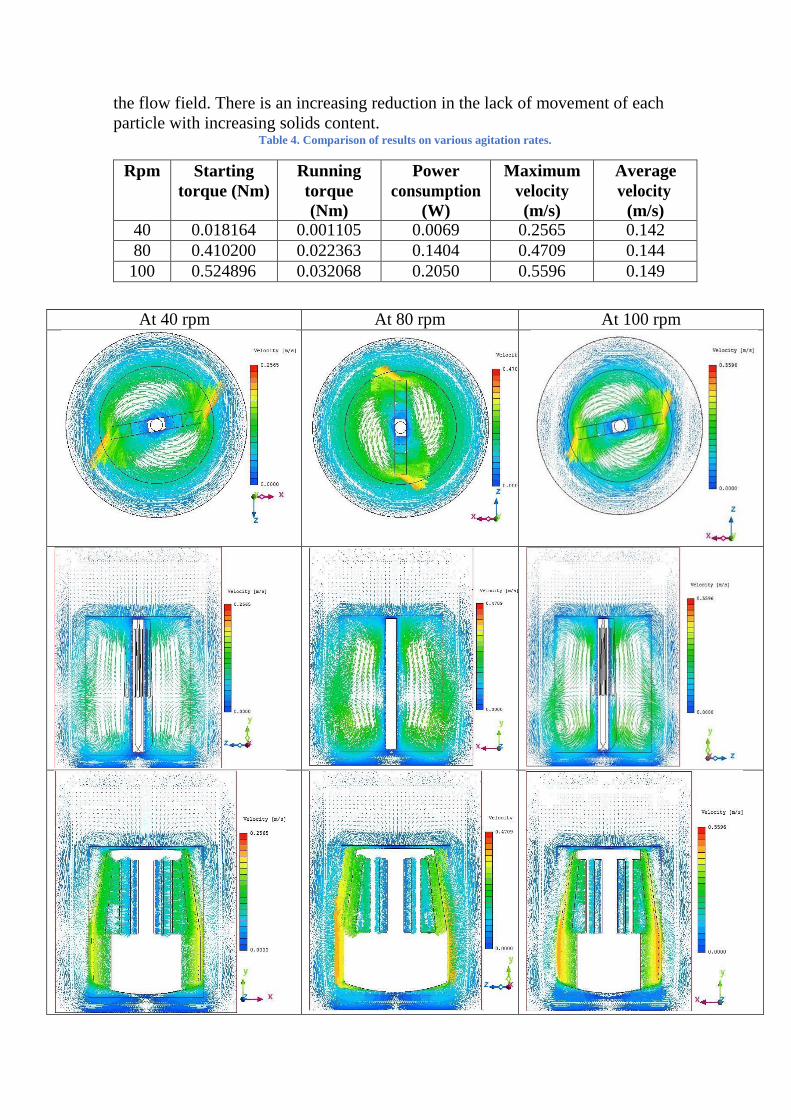
the flow field. There is an increasing reduction in the lack of movement of each
particle with increasing solids content. Table 4. Comparison of results on various agitation rates.
Rpm Starting
torque (Nm)
Running
torque
(Nm)
Power
consumption
(W)
Maximum
velocity
(m/s)
Average
velocity
(m/s) 40 0.018164 0.001105 0.0069 0.2565 0.142
80 0.410200 0.022363 0.1404 0.4709 0.144
100 0.524896 0.032068 0.2050 0.5596 0.149
At 40 rpm At 80 rpm At 100 rpm

Figure 4. Cfd simulation results at different rpm of maxblend impeller in vessel at different planes
6. CONCLUSION
Cfd results demonstrates that maxblend impeller possess good characteristics of
uniform distribution of velocity and viscosity.
Agitation rate of 80 and 100 rpm can be used for mixing in an anaerobic
digester. Further time of mixing operation can be optimized to check the
minimum power consumption.
Experimental approach can be continued with maxblend impeller to determine
the effect of mixing intensity on methane production.
Scaleup factor for large scale biogas plant is also very important aspect to be
considered during the designing of anaerobic digester.
REFERENCES
[1] Z. Szamosi, Zoltán; Tóth, Pál; Koós, Tamás; Baranyai, Viktor; Gábor,
Szepesi; Siménfalvi, “Explosion characteristics of torre ed wheat straw , rape
straw and vine shoots fuels University of Miskolc , Institute of Energy
Engineering and Chemical Machinery , A5 § Bay Zoltán Nonpro t Ltd . for
Applied Research , 1 Kondorfa u . 1116 Budapest , Hung,” 2017.
[2] SZAMOSI Zoltán and R.-C. Martí, “International scientific conference on
advances in mechanical engineering,” pp. 155–158.
[3] J. E. Sawyer, C. N. & Grumbling, “Fundamental considerations in high rate
digestionTitle,” J. Sanit. Eng. Div., Proc. Am. Soc. C. Eng, vol. 86 (SA2),
1960.
[4] A. Stenstrom MK, Ng AS, Bhunia PK, “Anaerobic digestion on municipal
solid waste.,” Environ. Eng., vol. 109, no. 5, pp. 1148–58, 1983.
[5] Z. S. Viktória MIKÁCZÓ, Gábor L. SZEPESI, “Simulation of propane
explosion in closed vessel 1-3. 1.,” 2017.
[6] B. Spis and R. Beleznai, “Design and Analysis of Composite Oil Pan for
Automotive Vehicle,” vol. 2, pp. 301–314, 2018.
DOI: 10.1007/978-3-319-75677-6_25
[7] S. Z. MIKÁCZÓ Viktória and S. L. Gábor, “INTERNATIONAL
SCIENTIFIC CONFERENCE ON INVESTIGATION OF DEFLECTOR
PLATES IN CASE OF GAS,” no. October, pp. 11–16, 2016.
[8] A. Lebranchu et al., “Impact of shear stress and impeller design on the
production of biogas in anaerobic digesters,” Bioresour. Technol., vol. 245,
no. June, pp. 1139–1147, 2017.
DOI: 10.1016/j.biortech.2017.07.113
[9] F. Battista, D. Fino, G. Mancini, and B. Ruggeri, “Mixing in digesters used to
treat high viscosity substrates: The case of olive oil production wastes,” J.
Environ. Chem. Eng., vol. 4, no. 1, pp. 915–923, 2016.
[10] V. Kállai, J. Kerezsi, P. Mizsey, and G. L. Szepesi, “Ethane- Ethylene
Rectification Column ’ s Parametric Examination,” vol. 70, pp. 1477–1482,
2018.
[11] G. L. Máté Petrik, Szepesi and T. Varga, “Numerical and Experimental Study
of Finned Tube Heat Transfer Characteristics,” vol. 1, pp. 563–570, 2018.
DOI: 10.1016/j.jece.2015.12.032
[12] M. Petrik and G. L. Szepesi, “Shell Side CFD Analysis of a Model Shell-and-
Tube Heat Exchanger,” vol. 70, pp. 313–318, 2018.
DOI: 10.3303/CET1870053
[13] A. Achkari-Begdouri and P. R. Goodrich, “Rheological properties of

Moroccan dairy cattle manure,” Bioresour. Technol., vol. 40, no. 2, pp. 149–
156, Jan. 1992.
DOI: 10.1016/0960-8524(92)90201-8