cfd topology and shape optimization with adjoint methods
TRANSCRIPT
VDI Fahrzeug- und Verkehrstechnik13. Internationaler Kongress
Berechnung und Simulation im FahrzeugbauWurzburg, September 2006
CFD TOPOLOGY AND SHAPE OPTIMIZATION WITHADJOINT METHODS
CFD-Topologie- und Formoptimierung mit Adjungierten-Methoden
Carsten Othmer, Volkswagen AG, Wolfsburg
Abstract. Automated process chains for optimal fluid dynamics design are gainingimportance in automotive applications. So far, industrial implementations of optimal de-sign processes in fluid dynamics are mostly restricted to shape optimization with bionicalgorithms. However, on the basis of the recent progress in fluid dynamic topology opti-mization, as well as in industrial applications of adjoint-based shape design, we proposean adjoint-based design process chain comprising both topology and shape optimization.Starting from the available installation space, this approach delivers a tailored optimalgeometry, making use of the whole potential of the available design space at each stage.The central element of this design process is the computation of sensitivity maps – forboth topological and shape sensitivities. We present the theory underlying the computa-tion of sensitivity maps via adjoint states, show sample maps for an air duct segment anda complete passenger car and point out the missing links of the proposed design processchain.
Kurzfassung. Automatisierte Prozessketten fur die stromungsmechanische Bauteilop-timierung gewinnen zunehmend an Bedeutung. Dabei beschranken sich die bereits imindustriellen Einsatz befindlichen Methoden fast ausschließlich auf die Anwendung bio-nischer Algorithmen auf CAD-parametrisierte Geometrien. Auf Basis der jungsten Fort-schritte in der CFD-Topologieoptimierung sowie industrieller Testanwendungen Adjun-gierten-basierter Formoptimierungswerkzeuge bietet sich allerdings eine auf Adjungierten-Methoden beruhende, sowohl Topologie- als auch Formoptimierung umfassende integraleProzesskette an. Ausgehend vom zur Verfugung stehenden Bauraum liefert sie einemaßgeschneiderte optimale Geometrie, wobei in jedem Optimierungsschritt die vorhan-dene Gestaltungsfreiheit bestmoglich ausgenutzt wird. Zentrales Element einer solchenProzesskette ist die Berechnung von Sensitivitats-Landkarten mittels Adjungierten-Me-thode. Wir stellen die solchen Landkarten zugrundeliegende Theorie dar, zeigen berech-nete Sensitivitats-Landkarten eines Klimakanalabschnitts sowie eines Gesamtfahrzeugsund weisen auf die noch fehlenden Glieder in der vorgeschlagenen Optimierungsprozess-kette hin.
CFD topology and shape optimization with adjoint methods
1 CFD optimization: current status and limitations
The classical way of part design for industrial applications comprises an iteration be-tween the design engineer and the measurement or computation department. Implement-ing automatic optimization methods into the development process has the potential ofshortening this iteration significantly. Such methods are based on a parametric geometrydescription and automatically yield a design that is optimal with respect to the desiredproperties and to the imposed constraints.
The techniques that are currently being employed for CFD optimization tasks in theautomotive development process are mainly robust workhorses of the bionic type, i.e.genetic algorithms and evolutionary strategies [1]-[4]. Typical applications range fromair ducts for cabin ventilation over intake ports to engine cooling jackets and exhaustsystems.
Although successfully applied in the series development process and being by far moreeffective than the conventional design process of trial and error, the limits of these methodsare quickly reached: (1) Their computational cost puts a hard constraint on the affordablenumber of design parameters, i. e. on the explorable design space, and (2) an efficient CADparametrization with, on the one hand, a maximum of design freedom and on the other,a complete controllability in terms of given design domain restrictions is not a trivial taskat all.
These two aspects are the actual challenges of current CFD optimization methodolo-gies. Possible remedies are (1) the use of adjoint methods, where the cost of a sensitivitycomputation is independent of the number of design variables, and (2) to perform theoptimization with a CAD-free geometry description, i. e. a surface mesh for shape op-timization and a volume mesh for topology optimization, respectively [5, 6]. What thislooks like for typical automotive optimization tasks will be demonstrated in the remainderof this paper. We first introduce the idea of adjoint-based computation of sensitivities,apply the methodology to the Navier-Stokes equations and employ it to compute topo-logical sensitivities of air ducts. Recent results of the application of a commercial adjointsolver to drag reduction of a complete passenger car are shown, before the paper closesby pointing out the open issues on the road towards an adjoint-based CFD optimizationprocess chain comprising both topology and shape optimization.
2 Computation of sensitivities with adjoint methods
While already established in the aerospace sector, adjoint methods have been recog-nized by the automotive industry as an efficient optimization tool only recently [6, 7].The adjoint approach to optimal design consists of (a) computing the sensitivities of thecost function via an adjoint state, and (b) feeding these sensitivities into a gradient-basedoptimization algorithm [8]-[11]. Gradient-based algorithms can of course be employed
CFD topology and shape optimization with adjoint methods
without making use of adjoint states. In that case, however, the conventional computa-tion of sensitivities of the cost function J wrt. the design parameters α = (α1, . . . , αn)T
via finite differences
dJ
dαk
=
(J(α + ∆αk) − J(α)
∆αk
)for each k,
incurs a computational cost of n + 1 solver calls. On the other hand, using an adjointstate, the whole sensitivity can be obtained via one call to the CFD solver (“primal”)and one call to the adjoint solver (“dual”), i. e. via two solver calls - independent of thenumber of design variables n. Thus, especially for problems with a huge number of designparameters, this method pays off.
It is this characteristic of the adjoint method – its cost independence of the number ofdesign variables – that opens up unparalleled possibilities for design optimization. Onedoes not have to concern oneself anymore with a complicated CAD parametrization, but –for the sake of maximum design freedom – can draw on plentiful resources: surface mesh orvolume mesh representations. The design parameters are then the normal displacementsof each of the surface nodes or the porosity value of each volume cell, respectively. Thus,one is dealing with a number of design variables of the order of 105 or even more whichcannot be handled by conventional methods anymore.
3 Topological sensitivities
In structure mechanics, topology optimization is a well-established concept for designoptimization with respect to tension or stiffness [12]. Its transfer to computational fluiddynamics, however, just began three years ago with the pioneering work of Borrvall andPetersson [13]. Since then, this topic has received quite some interest both in academiaand in the industry [14]-[21].
The starting point for fluid dynamic topology optimization is a volume mesh of theentire installation space. Based on a computation of the flow solution inside this domain,a suitable local criterion is applied to decide whether a fluid cell is “good” or “bad” forthe flow in terms of the chosen cost function. In order to iteratively remove the identifiedbad cells from the fluid domain, they are either punished via a momentum loss term, orholes are inserted into the flow domain, with their positions being determined from anevaluation of the so-called topological asymptotic.
In the former case, the momentum loss term is usually realized via a finite cell porosity,i. e. the whole design domain is treated as a porous medium: Each cell is assigned anindividual porosity αi, which is modeled via Darcy’s law. The value of αi determines ifthe cell is fluid-like (low porosity values) or has a rather solid character (high values ofαi). In other words, the porosity field controls the geometry, and the αi are the actualdesign variables.
CFD topology and shape optimization with adjoint methods
With such a setting, an adjoint method can be applied to elegantly compute the sensi-tivities of the chosen cost function wrt. the porosity of each cell. The obtained sensitivitiescan then be fed into a gradient-based optimization algorithm – possibly with some penal-ization of intermediate porosity values in order to enforce a “digital” porosity distribution,and after several iterations, the desired optimum topology is finally extracted as an iso-surface of the obtained porosity distribution or simply as the collection of all non-porouscells.
In a recent study, Othmer et al. [21] were able to verify the applicability of this method-ology to typical automotive objective functions, including dissipated power, equal massflow through different outlets, flow uniformity and angular momentum of the flow inthe outlet plane. In that proof-of-concept study, Automatic Differentiation techniqueswere applied to an academic CFD code in order to obtain a discrete adjoint solver. Forindustrial-sized problems, however, this code is not suitable. Therefore, we implementedthe methodology via a continuous adjoint into the professional CFD environment Open-FOAM [22]. The underlying equations of this implementation will be shown in the fol-lowing section, before we show examples of topological sensitivity maps for an air ductsegment.
3.1 Implemented equations
As a starting point, we use the incompressible, steady-state Navier-Stokes equationswith a Darcy term to account for porosity:
(v · ∇)v = −∇p + ∇ · (ν ∇v) − αv (1)
∇ · v = 0 (2)
with velocity v, pressure p, viscosity ν and porosity α. Choosing the cost function to bee. g. the total pressure drop
J =∫in
pt dA −∫
out
pt dA , (3)
the corresponding Lagrange function reads
L = J +∫Ω
(u, q) R dΩ , (4)
with adjoint velocity u, adjoint pressure q and
R = (R1, R2, R3, R4)T (5)
being the residuals of the Navier-Stokes equations, i. e.
(R1, R2, R3)T = (v · ∇)v + ∇p −∇ · (ν ∇v) + αv (6)
R4 = −∇ · v . (7)
CFD topology and shape optimization with adjoint methods
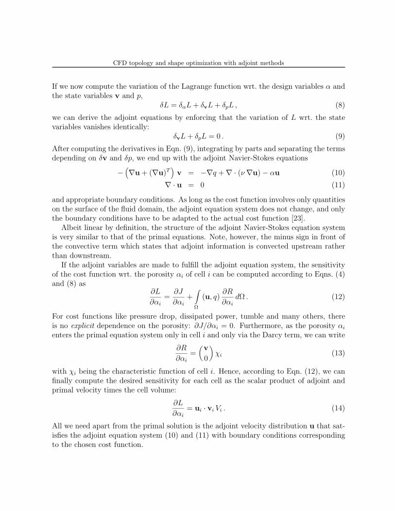
If we now compute the variation of the Lagrange function wrt. the design variables α andthe state variables v and p,
δL = δαL + δvL + δpL , (8)
we can derive the adjoint equations by enforcing that the variation of L wrt. the statevariables vanishes identically:
δvL + δpL = 0 . (9)
After computing the derivatives in Eqn. (9), integrating by parts and separating the termsdepending on δv and δp, we end up with the adjoint Navier-Stokes equations
−(∇u + (∇u)T
)v = −∇q + ∇ · (ν ∇u) − αu (10)
∇ · u = 0 (11)
and appropriate boundary conditions. As long as the cost function involves only quantitieson the surface of the fluid domain, the adjoint equation system does not change, and onlythe boundary conditions have to be adapted to the actual cost function [23].
Albeit linear by definition, the structure of the adjoint Navier-Stokes equation systemis very similar to that of the primal equations. Note, however, the minus sign in front ofthe convective term which states that adjoint information is convected upstream ratherthan downstream.
If the adjoint variables are made to fulfill the adjoint equation system, the sensitivityof the cost function wrt. the porosity αi of cell i can be computed according to Eqns. (4)and (8) as
∂L
∂αi
=∂J
∂αi
+∫Ω
(u, q)∂R
∂αi
dΩ . (12)
For cost functions like pressure drop, dissipated power, tumble and many others, thereis no explicit dependence on the porosity: ∂J/∂αi = 0. Furthermore, as the porosity αi
enters the primal equation system only in cell i and only via the Darcy term, we can write
∂R
∂αi
=(v
0
)χi (13)
with χi being the characteristic function of cell i. Hence, according to Eqn. (12), we canfinally compute the desired sensitivity for each cell as the scalar product of adjoint andprimal velocity times the cell volume:
∂L
∂αi
= ui · vi Vi . (14)
All we need apart from the primal solution is the adjoint velocity distribution u that sat-isfies the adjoint equation system (10) and (11) with boundary conditions correspondingto the chosen cost function.
CFD topology and shape optimization with adjoint methods
3.2 Sample applications
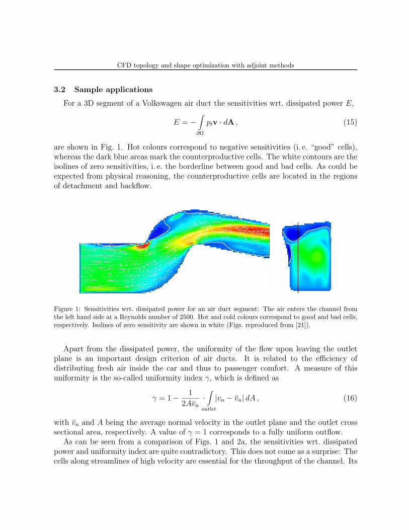
For a 3D segment of a Volkswagen air duct the sensitivities wrt. dissipated power E,
E = −∫
∂Ω
ptv · dA , (15)
are shown in Fig. 1. Hot colours correspond to negative sensitivities (i. e. “good” cells),whereas the dark blue areas mark the counterproductive cells. The white contours are theisolines of zero sensitivities, i. e. the borderline between good and bad cells. As could beexpected from physical reasoning, the counterproductive cells are located in the regionsof detachment and backflow.
Figure 1: Sensitivities wrt. dissipated power for an air duct segment: The air enters the channel fromthe left hand side at a Reynolds number of 2500. Hot and cold colours correspond to good and bad cells,respectively. Isolines of zero sensitivity are shown in white (Figs. reproduced from [21]).
Apart from the dissipated power, the uniformity of the flow upon leaving the outletplane is an important design criterion of air ducts. It is related to the efficiency ofdistributing fresh air inside the car and thus to passenger comfort. A measure of thisuniformity is the so-called uniformity index γ, which is defined as
γ = 1 − 1
2Avn
·∫
outlet
|vn − vn| dA , (16)
with vn and A being the average normal velocity in the outlet plane and the outlet crosssectional area, respectively. A value of γ = 1 corresponds to a fully uniform outflow.
As can be seen from a comparison of Figs. 1 and 2a, the sensitivities wrt. dissipatedpower and uniformity index are quite contradictory. This does not come as a surprise: Thecells along streamlines of high velocity are essential for the throughput of the channel. Its
CFD topology and shape optimization with adjoint methods
energetic efficiency would therefore strongly deteriorate if some finite porosity was addedto these cells. On the other hand, in order to improve the flow uniformity, it is exactlythese high-velocity cells that have to be slowed down by increasing their porosity.
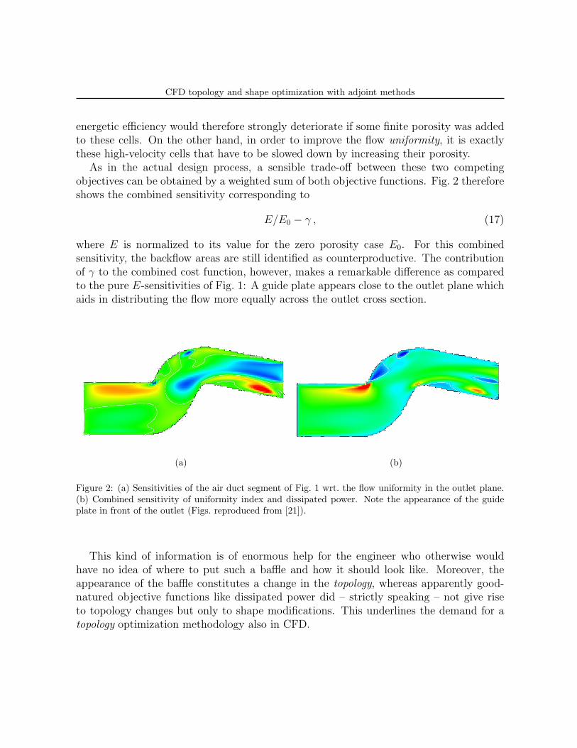
As in the actual design process, a sensible trade-off between these two competingobjectives can be obtained by a weighted sum of both objective functions. Fig. 2 thereforeshows the combined sensitivity corresponding to
E/E0 − γ , (17)
where E is normalized to its value for the zero porosity case E0. For this combinedsensitivity, the backflow areas are still identified as counterproductive. The contributionof γ to the combined cost function, however, makes a remarkable difference as comparedto the pure E-sensitivities of Fig. 1: A guide plate appears close to the outlet plane whichaids in distributing the flow more equally across the outlet cross section.
(a) (b)
Figure 2: (a) Sensitivities of the air duct segment of Fig. 1 wrt. the flow uniformity in the outlet plane.(b) Combined sensitivity of uniformity index and dissipated power. Note the appearance of the guideplate in front of the outlet (Figs. reproduced from [21]).
This kind of information is of enormous help for the engineer who otherwise wouldhave no idea of where to put such a baffle and how it should look like. Moreover, theappearance of the baffle constitutes a change in the topology, whereas apparently good-natured objective functions like dissipated power did – strictly speaking – not give riseto topology changes but only to shape modifications. This underlines the demand for atopology optimization methodology also in CFD.

CFD topology and shape optimization with adjoint methods
4 Shape sensitivities
An inherent feature of topology optimization is the ragged surface of the resultinggeometries. A CFD computation on such a geometry can obviously not be as accurate ason a body-fitted mesh. Therefore, the virtue of topology optimization lies rather in theefficient drafting of designs than in geometrical fine-tuning. For the latter, optimizationmethodologies operating directly on the shape have to be employed.
That adjoint methods are the method of choice also for shape optimization tasks iswell documented by hundreds of publications from the aerospace community over thelast two decades. In recent studies, adjoint methods were shown to be efficient shapeoptimization tools also for automotive applications [6, 7]. In [6], a benchmark betweena conventional bionic optimization and ESI’s PAMFlow Adjoint Solver was carried out:Both methodologies were applied to pressure drop optimization of an air duct segment.With the adjoint solver, it took two design iterations to achieve a 20% reduction of thepressure drop, whereas the bionic algorithm had to perform 600 cost function evaluations,i. e. 600 CFD runs, to achieve the same level of performance improvement.
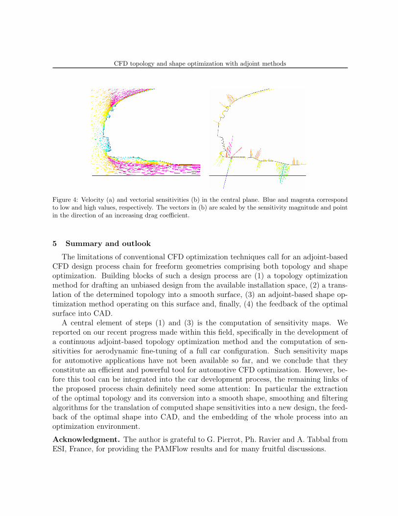
After these promising results, we decided to extend the evaluation of adjoint methodsfor shape optimization to the task of drag reduction of a production passenger car: Anexternal aerodynamics computation for the current Volkswagen Golf was carried out withPAMFlow, and the time-averaged results were fed into PAMFlow’s Adjoint Solver. Foreach node of the surface mesh, the sensitivity of the total drag force was thus obtained,i. e. the partial derivative of the total drag force wrt. a nodal displacement in the outwardnormal direction. The sensitivities for hat and underbody are displayed in Fig. 3, andFig. 4 shows a close-up of the flow and of the vectorial sensitivities in the central plane.
It is the first time that such computations have been performed for a complete car, andwe are still in the process of learning to understand the wealth of information contained inthese sensitivity maps. The central question is, of course, if this information actually goesbeyond the “usual suspects”, i. e. beyond the vast experience of aerodynamic engineers,and, if it does, how it can sensibly be exploited to optimize the aerodynamic performanceof the car.
Indeed, the qualitative distribution of sensitivities on the car hat (Fig. 3a) is – onthe whole – much as expected. The flow around the car hat is rather simple, so thatthe qualitative effect of shape changes are either well-known already or can be predictedquite easily. The added value of the sensitivity map, however, lies in its degree of detail(note e. g. the sensitivity distribution around the C-pillar in Fig. 3a), and in deliveringquantitative information on the impact of local shape changes on the drag coefficient.
For the car underbody, the benefit of the sensitivity map over experience is quiteobvious: The flow here is so complex that the computation of sensitivities is the only wayof identifying effective shape changes. That is why, for an assessment of the usefulnessof sensitivity maps for drag optimization, we focus on the underbody: In a still ongoing
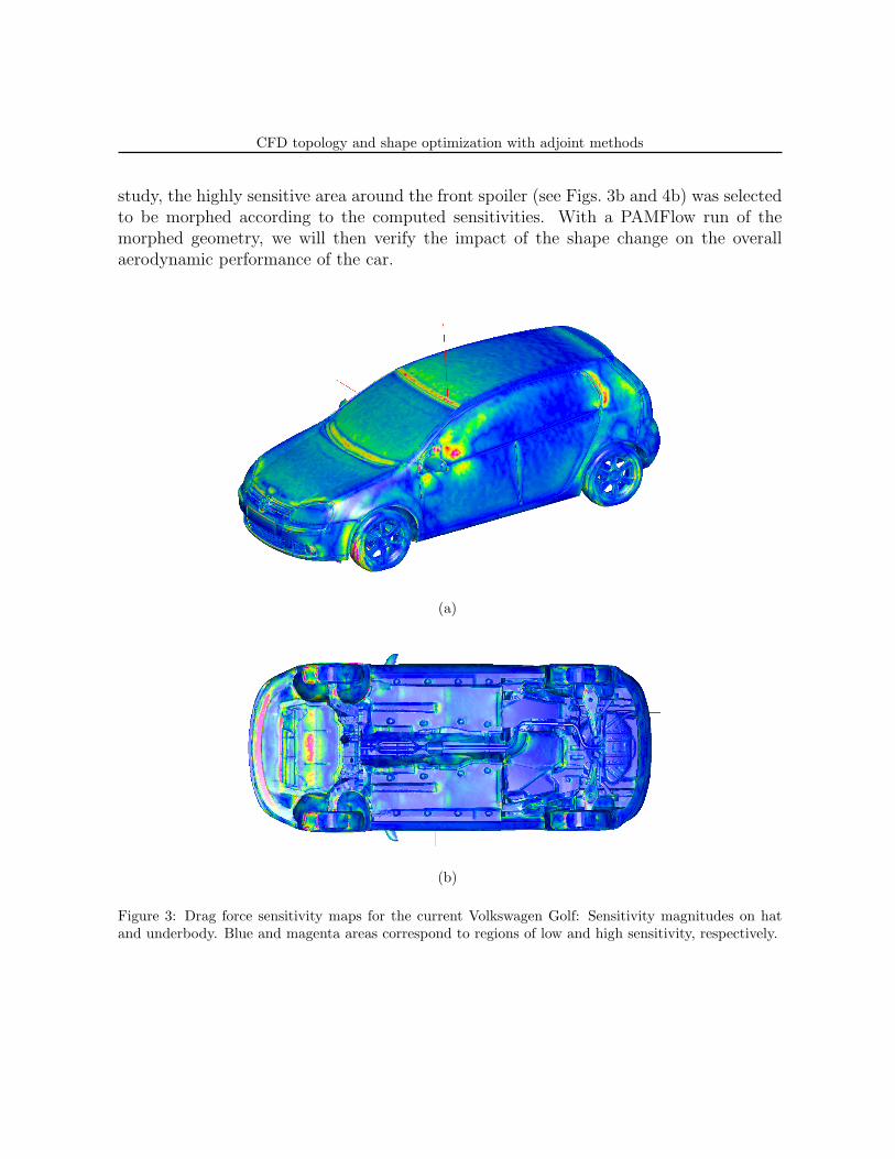
CFD topology and shape optimization with adjoint methods
study, the highly sensitive area around the front spoiler (see Figs. 3b and 4b) was selectedto be morphed according to the computed sensitivities. With a PAMFlow run of themorphed geometry, we will then verify the impact of the shape change on the overallaerodynamic performance of the car.
(a)
(b)
Figure 3: Drag force sensitivity maps for the current Volkswagen Golf: Sensitivity magnitudes on hatand underbody. Blue and magenta areas correspond to regions of low and high sensitivity, respectively.
CFD topology and shape optimization with adjoint methods
Figure 4: Velocity (a) and vectorial sensitivities (b) in the central plane. Blue and magenta correspondto low and high values, respectively. The vectors in (b) are scaled by the sensitivity magnitude and pointin the direction of an increasing drag coefficient.
5 Summary and outlook
The limitations of conventional CFD optimization techniques call for an adjoint-basedCFD design process chain for freeform geometries comprising both topology and shapeoptimization. Building blocks of such a design process are (1) a topology optimizationmethod for drafting an unbiased design from the available installation space, (2) a trans-lation of the determined topology into a smooth surface, (3) an adjoint-based shape op-timization method operating on this surface and, finally, (4) the feedback of the optimalsurface into CAD.
A central element of steps (1) and (3) is the computation of sensitivity maps. Wereported on our recent progress made within this field, specifically in the development ofa continuous adjoint-based topology optimization method and the computation of sen-sitivities for aerodynamic fine-tuning of a full car configuration. Such sensitivity mapsfor automotive applications have not been available so far, and we conclude that theyconstitute an efficient and powerful tool for automotive CFD optimization. However, be-fore this tool can be integrated into the car development process, the remaining links ofthe proposed process chain definitely need some attention: In particular the extractionof the optimal topology and its conversion into a smooth shape, smoothing and filteringalgorithms for the translation of computed shape sensitivities into a new design, the feed-back of the optimal shape into CAD, and the embedding of the whole process into anoptimization environment.
Acknowledgment. The author is grateful to G. Pierrot, Ph. Ravier and A. Tabbal fromESI, France, for providing the PAMFlow results and for many fruitful discussions.
CFD topology and shape optimization with adjoint methods
REFERENCES
[1] G. Rottger, M.T. Abad Lozano, M. Kiel, and J. Willand, Automated Intake PortGeometry Optimisation by means of Genetic Algorithms and 3D-CFD, 22nd CAD-FEM User Meeting, Dresden, 2004.
[2] C. Othmer and P. van Vooren, Optimization of Engine Cooling using Vectis andOptimus, Ricardo Software European User Conference, Frankfurt, 2004.
[3] C. Othmer et al., Stromungsmechanische Optimierung: Anwendungsbeispiele ausder Motorenentwicklung, CAE-Optimierung in der Fahrzeugentwicklung, Haus derTechnik, Hamburg, 2004.
[4] P. Nefischer and M. Cecchini, Use of Optimisation Tools in CFD, 13th EuropeanStar-CD User Conference, London, 2004.
[5] C. Othmer et al., Black Box, Adjoint and Topology: Three options for CFD opti-mization, NAFEMS Seminar, Wiesbaden, 2005.
[6] C. Othmer and Th. Grahs, Approaches to fluid dynamic optimization in the cardevelopment process, EUROGEN 2005, Munich, 2005.
[7] C. Othmer, Ph. Ravier, and G. Pierrot, Adjoint methods for automotive CFD opti-mization, PUCA 2005, Tokyo, 2005.
[8] A. Jameson, Aerodynamic Shape Optimization Using the Adjoint Method, VKI Lec-ture Series 2003-02, Brussels, 2003.
[9] M.B. Giles and N.A. Pierce, An Introduction to the Adjoint Approach to Design,Flow, Turbulence and Combustion, 65, 393–415, 2000.
[10] B. Mohammadi and O. Pironneau, Applied Shape Optimization for Fluids, OxfordUniversity Press, 2001.
[11] R. Lohner, O. Soto, and C. Yang, An Adjoint-Based Design Methodology for CFDOptimization Problems, AIAA-03-0299, 2003.
[12] M.P. Bendsøe and O. Sigmund, Topology optimization: theory, methods, and appli-cations, Springer, Berlin, 2004.
[13] T. Borrvall and J. Petersson, Topology optimization of fluids in Stokes flow, Int. J.Num. Meth. Fluids, 41, p. 77, 2003.
CFD topology and shape optimization with adjoint methods
[14] O. Sigmund, A. Gersborg-Hansen, and R.B. Haber, Topology optimization for multi-physics problems: A future FEMLAB application?, Proc. Nordic MATLAB Conf.2003, L. Gregersen (Ed.), Comsol A/S, Søborg, Denmark, p. 237, 2003.
[15] L.H. Olesen, F. Okkels, and H. Bruus, Topology optimization of Navier-Stokes flowin microfluidics, ECCOMAS 2004, Jyvaskyla, 2004.
[16] O. Moos, F.R. Klimetzek, and R. Rossmann, Bionic optimization of air-guiding sys-tems, SAE 2004-01-1377, 2004.
[17] J.K. Guest and J.H. Prevost, Topology optimization of creeping flows using a Darcy-Stokes finite element, Int. J. Num. Meth. Engng., 66 (3), p. 461, 2006.
[18] M. Hassine, S. Jan, and M. Masmoudi, From differential calculus to 0-1 optimization,ECCOMAS 2004, Jyvaskyla, 2004.
[19] S. Amstutz, Topological sensitivity in fluid dynamics, ECCOMAS 2004, Jyvaskyla,2004.
[20] Th. Kaminski, R. Giering, and C. Othmer, Topological design based on highly effi-cient adjoints generated by automatic differentiation, ERCOFTAC Design Optimiza-tion Conf., Las Palmas, 2006.
[21] C. Othmer, Th. Kaminski, and R. Giering, Computation of topological sensitivitiesin fluid dynamics: Cost function versatility, ECCOMAS CFD 2006, Delft, 2006.
[22] http://www.opencfd.co.uk/openfoam/www.opencfd.org
[23] C. Othmer, A non-specialist’s guide to adjoint-based computation of sensitivities, in:Optimal Shape Design in Fluid Dynamics, Lecture notes, Winter term 2006/2007,TU Braunschweig.